WO2021140873A1 - Dispositif de traitement d'image, procédé de traitement d'image, et dispositif d'imagerie - Google Patents
Dispositif de traitement d'image, procédé de traitement d'image, et dispositif d'imagerie Download PDFInfo
- Publication number
- WO2021140873A1 WO2021140873A1 PCT/JP2020/047434 JP2020047434W WO2021140873A1 WO 2021140873 A1 WO2021140873 A1 WO 2021140873A1 JP 2020047434 W JP2020047434 W JP 2020047434W WO 2021140873 A1 WO2021140873 A1 WO 2021140873A1
- Authority
- WO
- WIPO (PCT)
- Prior art keywords
- pixel
- polarized
- pixels
- image
- polarization
- Prior art date
Links
Images


Classifications
-
- H—ELECTRICITY
- H04—ELECTRIC COMMUNICATION TECHNIQUE
- H04N—PICTORIAL COMMUNICATION, e.g. TELEVISION
- H04N23/00—Cameras or camera modules comprising electronic image sensors; Control thereof
- H04N23/80—Camera processing pipelines; Components thereof
- H04N23/84—Camera processing pipelines; Components thereof for processing colour signals
- H04N23/843—Demosaicing, e.g. interpolating colour pixel values
-
- H—ELECTRICITY
- H04—ELECTRIC COMMUNICATION TECHNIQUE
- H04N—PICTORIAL COMMUNICATION, e.g. TELEVISION
- H04N25/00—Circuitry of solid-state image sensors [SSIS]; Control thereof
- H04N25/60—Noise processing, e.g. detecting, correcting, reducing or removing noise
- H04N25/68—Noise processing, e.g. detecting, correcting, reducing or removing noise applied to defects
- H04N25/683—Noise processing, e.g. detecting, correcting, reducing or removing noise applied to defects by defect estimation performed on the scene signal, e.g. real time or on the fly detection
-
- H—ELECTRICITY
- H04—ELECTRIC COMMUNICATION TECHNIQUE
- H04N—PICTORIAL COMMUNICATION, e.g. TELEVISION
- H04N25/00—Circuitry of solid-state image sensors [SSIS]; Control thereof
- H04N25/10—Circuitry of solid-state image sensors [SSIS]; Control thereof for transforming different wavelengths into image signals
- H04N25/11—Arrangement of colour filter arrays [CFA]; Filter mosaics
- H04N25/13—Arrangement of colour filter arrays [CFA]; Filter mosaics characterised by the spectral characteristics of the filter elements
-
- H—ELECTRICITY
- H04—ELECTRIC COMMUNICATION TECHNIQUE
- H04N—PICTORIAL COMMUNICATION, e.g. TELEVISION
- H04N25/00—Circuitry of solid-state image sensors [SSIS]; Control thereof
- H04N25/60—Noise processing, e.g. detecting, correcting, reducing or removing noise
- H04N25/63—Noise processing, e.g. detecting, correcting, reducing or removing noise applied to dark current
- H04N25/633—Noise processing, e.g. detecting, correcting, reducing or removing noise applied to dark current by using optical black pixels
-
- H—ELECTRICITY
- H04—ELECTRIC COMMUNICATION TECHNIQUE
- H04N—PICTORIAL COMMUNICATION, e.g. TELEVISION
- H04N25/00—Circuitry of solid-state image sensors [SSIS]; Control thereof
- H04N25/70—SSIS architectures; Circuits associated therewith
- H04N25/76—Addressed sensors, e.g. MOS or CMOS sensors
- H04N25/77—Pixel circuitry, e.g. memories, A/D converters, pixel amplifiers, shared circuits or shared components
Definitions
- This technology makes it possible to acquire highly accurate polarization information regarding an image processing device, an image processing method, and an imaging device.
- Patent Document 1 discloses a method in which a patterned polarizer and a color mosaic filter are arranged in front of an image sensor to image a subject, and color information and polarization information are acquired based on the obtained polarized image. ing. Further, in Patent Document 2, by using not only a polarized image showing a polarized component but also a non-polarized image in which a decrease in the amount of light does not occur, polarized information with higher accuracy than in the case of generating polarized information based on the polarized image is used. Is disclosed.
- this technology provides an image processing device, an image processing method, and an imaging device that can acquire correct polarization information.
- the first aspect of this technology is An invalid pixel detection unit that detects saturated pixels and blackened pixels as invalid pixels from an unpolarized image obtained by imaging using a polarized light imaging unit and a plurality of polarized images having different polarization directions.
- An image processing apparatus including a polarization information generating unit that performs polarization information generation processing based on the unpolarized image and the polarized image and switches the polarization information generation processing according to the detection result of the invalid pixel in the invalid pixel detection unit. It is in.
- the invalid pixel detection unit detects invalid pixels from a plurality of polarized images having different polarization directions from the unpolarized image obtained by performing imaging using the polarized imaging unit.
- the invalid pixel detection unit defines saturated pixels having a pixel value larger than a preset saturation detection threshold value from an unpolarized image and black crushed pixels having a pixel value smaller than a preset blackout detection threshold value as invalid pixels.
- the saturation detection threshold value and the blackout detection threshold value may be set according to the characteristics of the image acquired by performing imaging with the polarized light imaging unit.
- the blackout detection threshold is set to be larger than the output minimum value of the polarized light imaging unit by the first level
- the saturation detection threshold is set to be smaller than the output maximum value of the polarized light imaging unit by the second level, which is smaller than the first level.
- the polarization information generation unit performs polarization information generation processing based on the unpolarized image and the polarized image, and switches the polarization information generation processing according to the detection result of invalid pixels in the invalid pixel detection unit. For example, when the unpolarized image pixel is detected as an invalid pixel, the polarization information generation unit detects the unpolarized image pixel and the unpolarized pixel, or at least two or more polarized images whose polarization directions are not orthogonal to each other. Polarization information is generated using pixels.
- the plurality of polarized images are three or more polarized images having different polarization directions, and the polarization information generator uses polarized information using at least two polarized image pixels that are not detected as unpolarized image pixels and invalid pixels. To generate. Further, when the invalid pixel is not detected, the polarization information generation unit generates polarization information using the pixel of the unpolarized image and the pixel of the polarized image.
- the invalid pixel detection unit detects saturated pixels and blackened pixels as invalid pixels from the unpolarized image obtained by imaging using the polarized image pickup unit and a plurality of polarized images having different polarization directions.
- the polarization information generation unit includes performing polarization information generation processing based on the unpolarized image and the polarized image, and switching the polarization information generation processing according to the detection result of the invalid pixel in the invalid pixel detection unit. It is in the image processing method.
- the third aspect of this technology is A program that causes a computer to generate polarization information.
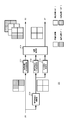
- FIG. 1 illustrates a configuration of a system using an image processing device.
- the system 10 has a polarized light imaging unit 20 and an image processing unit 30.
- the polarized light imaging unit 20 is arranged with unpolarized pixels and polarized pixels provided in at least two polarization directions, and generates an image signal of the captured image and outputs it to the image processing unit 30.
- FIG. 2 illustrates the configuration of the polarized light imaging unit.
- the polarized light imaging unit 20 has a configuration in which a polarizing filter 22 is arranged on an incident surface of an image sensor 21 such as a CMOS (Complementary Metal Oxide Semiconductor) or a CCD (Charge Coupled Device).
- CMOS Complementary Metal Oxide Semiconductor
- CCD Charge Coupled Device
- FIG. 3 illustrates the configuration of the image sensor.
- the image sensor 21 includes a pixel array unit 211 in which a plurality of pixels are arranged in an array, for example, a two-dimensional matrix, a vertical scanning circuit 212 and a horizontal scanning circuit 213 that control the drive of the pixel array unit 211. ing.
- the pixel array unit 211 shows only a part of the pixels in the row direction and the column direction.
- the pixels of the pixel array unit 211 have a photodiode and a transistor for charge transfer and reset, although not shown. Each pixel is connected to the vertical scanning circuit 212 via a reset line and a selection line, and is connected to the horizontal scanning circuit 213 via a signal line.
- the vertical scanning circuit 212 outputs a reset signal to a pixel reset transistor via a reset line to discharge accumulated charges. After that, the vertical scanning circuit 212 outputs the read signal to the charge transfer transistors of the polarized pixel and the unpolarized pixel via the selection line, and the exposure period from the output of the reset signal to the output of the read signal. The electric charge accumulated in the signal is output to the signal line as a signal current.
- the horizontal scanning circuit 213 performs a process of converting the signal current read from each pixel into a digital pixel signal, a gain adjustment process of the pixel signal, and the like, and the processed pixel signal is image processing unit 30 in the order of pixels in the horizontal direction. Output to. Further, the vertical scanning circuit 212 and the horizontal scanning circuit 213 perform the above-mentioned processing for each line.
- FIG. 4 illustrates the pixel configuration of the polarizing filter.
- the polarizing filter 22 is composed of unpolarized pixels and polarized pixels in at least two polarization directions, and a photonic liquid crystal, a wire grid, or the like is used as the polarized pixels.
- FIG. 4A illustrates a case where the polarizing filter 22 is composed of unpolarized pixels and three polarized pixels having different polarization directions.
- the polarizing filter 22 is composed of, for example, a 2 ⁇ 2 pixel region as a polarized pixel block, and the polarized pixel block is composed of one unpolarized pixel and three polarized pixels having polarization directions of “0 °, 90 °, 135 °”.
- the polarized pixel block is repeatedly provided in the horizontal direction and the vertical direction.
- FIG. 4B illustrates a case where the polarizing filter 22 is composed of an unpolarized pixel and two polarized pixels having different polarization directions.
- the polarizing filter 22 is composed of, for example, a 2 ⁇ 2 pixel region as a polarized pixel block, and the polarized pixel block is composed of two unpolarized pixels and two polarized pixels having polarization directions of “90 ° and 135 °”. Polarized pixel blocks are repeatedly provided in the horizontal and vertical directions.
- the polarized image pickup unit 20 configured in this way generates an image signal of an image captured image composed of polarized pixels and unpolarized pixels by sequentially reading out pixel signals, and outputs the image signal to the image processing unit 30. Further, the polarized light imaging unit 20 may control the reset timing of the unpolarized pixel and set the exposure period of the unpolarized pixel so that the unpolarized pixel becomes equal to the sensitivity of the polarized pixel.
- the image processing unit 30 has a demosaic processing unit 31, an invalid pixel detection unit 32, and a polarization information generation unit 33.
- the demosaic processing unit 31 may be provided in the polarized light imaging unit 20.
- the demosaic processing unit 31 generates an unpolarized image and a polarized image for each polarization direction from the captured image acquired by the polarized light imaging unit 20.
- the demosaic processing unit 31 includes polarized pixels at pixel positions in the same polarization direction in the pixels of interest and peripheral pixels of the pixels of interest in the captured image acquired by the polarized imaging unit 20, pixel positions equal to the polarized pixels, and pixel positions of the pixels of interest.
- the pixel value of the polarized pixel at the pixel position of the pixel of interest is calculated for each polarization direction using the non-polarized pixel of.
- the demosaic processing unit 31 considers that there is a positive correlation between the unpolarized pixel and the polarized pixel, and generates a high-resolution polarized image by supplementing the high-frequency component lost in the polarized image from the unpolarized image. To do.
- the demosaic processing unit uses the relationship between the pixel average value of the unpolarized pixel at the pixel position in the same polarization direction and the pixel value of the unpolarized pixel at the pixel position of the pixel of interest, and the pixel position at the same polarization direction.
- the pixel value of the polarized pixel at the pixel position of the pixel of interest with respect to the pixel average value of the polarized pixel is calculated.
- FIG. 5 illustrates the configuration of the demosaic processing unit.
- the demosaic processing unit 31 includes an unpolarized pixel interpolation unit 310 for generating an unpolarized image, a polarized pixel averaging processing unit 311 for generating a high-resolution polarized image using the unpolarized image, and an unpolarized pixel. It has an averaging processing unit 312, a central pixel acquisition unit 313, and a correlation processing unit 314.
- the non-polarized pixel interpolation unit 310 interpolates the pixel values at the pixel positions where the pixel values of the unpolarized pixels are not obtained in the captured image acquired by the polarized image pickup unit 20 by using the pixel values of the peripheral unpolarized pixels.
- a non-polarized image is generated by calculating by processing or the like.
- the non-polarized pixel interpolation unit 310 outputs the generated non-polarized image to the non-polarized pixel averaging processing unit 312 and the center pixel acquisition unit 313.
- the polarized pixel averaging processing unit 311 calculates the pixel average value for the pixel of interest for each polarization direction using the pixel of interest and the peripheral pixels located around the pixel of interest, and outputs the pixel average value to the correlation processing unit 314.
- the non-polarized pixel averaging processing unit 312 uses the attention pixel and peripheral pixels located around the attention pixel, and has the same pixel position as when the polarized pixel averaging processing unit 311 calculates the pixel average value for each polarization direction.
- the pixel average value is calculated from the pixels and output to the correlation processing unit 314.
- the central pixel acquisition unit 313 extracts the pixel value of the pixel of interest from the unpolarized image and outputs it to the correlation processing unit 314.
- the correlation processing unit 314 has a pixel average value for each polarization direction calculated by the polarized pixel averaging processing unit 311 and a pixel average value calculated by the unpolarized pixel averaging processing unit 312 corresponding to the pixel average value for each polarization direction. Then, the pixel value for each polarization direction of the pixel of interest is calculated from the pixel value of the pixel of interest extracted by the center pixel acquisition unit 313.
- the demosaic process of polarized pixels will be described with reference to FIG. FIG. 6A shows a polarized image, and FIG. 6B shows a non-polarized image.
- the polarized pixel averaging processing unit 311 has a pixel position of interest "x, y" and peripheral pixel positions "x-1, y-1", “x, y-1", “x + 1, y-1” and "x + 1, y-1” in the polarized image. Calculate the pixel average value for each polarization direction using the pixels of "x-1, y", “x + 1, y”, “x-1, y + 1", "x, y + 1", and "x + 1, y + 1". ..
- the pixel value of the pixel position of interest in the polarized image is "P (x, y)", and the pixel value of the peripheral pixel position is "P (x-1, y-1)" "P (x, y-1)”.
- P (x + 1, y-1) "P (x-1, y)”
- P (x + 1, y) "P (x + 1, y)”
- P (x-1, y + 1) P (x-1, y + 1)
- P (x, y) y + 1)
- the pixel value of the pixel position of interest in the unpolarized image is "Q (x, y)", and the pixel value of the peripheral pixel position is "Q (x-1, y-1)" "Q (x, y-1)”.
- Q (x + 1, y-1) "Q (x-1, y)”
- Q (x + 1, y) "Q (x + 1, y)”
- Q (x-1, y + 1) Q (x-1, y + 1)
- Q (x, y) y + 1) and“ Q (x + 1, y + 1) ”.
- mP0 (x, y) P (x, y) ⁇ ⁇ ⁇ (1)
- mP1 (x, y) (P (x-1, y-1) + P (x + 1, y-1) + P (x-1, y + 1) + P (x + 1, y + 1)) / 4 ⁇ ⁇ ⁇ (2)
- mP2 (x, y) (P (x, y-1) + P (x, y + 1)) / 2 ...
- the unpolarized pixel averaging processing unit 312 calculates the pixel average value from the pixel value at the pixel position equal to the case of calculating the pixel average value for each polarization direction by using the attention pixel and the peripheral pixels of the attention pixel in the unpolarized image. To do.
- mQ0 (x, y) Q (x, y) ⁇ ⁇ ⁇ (4)
- mQ1 (x, y) (Q (x-1, y-1) + Q (x + 1, y-1) + Q (x-1, y + 1) + Q (x + 1, y + 1)) / 4 ⁇ ⁇ ⁇ (5)
- mQ2 (x, y) (Q (x, y-1) + Q (x, y + 1)) / 2 ... (6)
- the correlation processing unit 314 considers that there is a positive correlation between the polarized pixel and the unpolarized pixel, and determines that the pixel average value calculated from the polarized image, the pixel average value calculated from the unpolarized image, and the pixel of interest in the unpolarized image. From the value, the pixel value for each polarization direction of the pixel position of interest is calculated.
- the correlation processing unit 314 outputs the pixel value Q (x, y) as the pixel value of the pixel of interest in the unpolarized image.
- P0 (x, y) mP0 (x, y) ⁇ Q (x, y) / mQ0 (x, y) ⁇ ⁇ ⁇ (7)
- P1 (x, y) mP1 (x, y) ⁇ Q (x, y) / mQ1 (x, y) ⁇ ⁇ ⁇ (8)
- P2 (x, y) mP2 (x, y) ⁇ Q (x, y) / mQ2 (x, y) ⁇ ⁇ ⁇ (9)
- the demosaic processing unit 31 generates a polarized image for each polarization direction by performing the above processing with each pixel of the polarized image as a pixel of interest. Further, since the signal component of the unpolarized pixel is normalized by the pixel average value and superimposed on the polarized pixel, the demosaic processing unit 31 can improve the problem such as folding back caused by the frequency limit of the polarized pixel. This makes it possible to generate a polarized image having the same resolution as an unpolarized image for each polarization direction.
- the pixel array corresponds to the Bayer array, for example, the document "B. Gunturk, J. Grotzbach, Y. Altumbasak, R. scaffer, and R.
- demosaic processing unit 31 only needs to be able to generate an unpolarized image and a polarized image for each polarization direction, and the demosaic processing is not limited to the above method.
- the invalid pixel detection unit 32 detects an invalid pixel by comparing a preset threshold value with the pixel values of the unpolarized pixel and the polarized pixel.
- a saturation detection threshold value Th for detecting saturated pixels and a black crushing detection threshold Thb for detecting black crushed pixels are set.
- the invalid pixel detection unit 32 compares the pixel value of each pixel with the saturation detection threshold value Th, and sets a pixel having a pixel value larger than the saturation detection threshold value The as an invalid pixel. Further, the invalid pixel detection unit 32 compares the pixel value of each pixel with the black crush detection threshold Thb, and sets a pixel having a pixel value smaller than the black crush detection threshold Thb as an invalid pixel.
- the unpolarized pixel is not provided with a polarizing filter and the amount of incident light is larger (higher sensitivity) than the polarized pixel, and the polarized pixel is reduced in the amount of light by the polarizing filter and the amount of incident light is larger than that of the polarized pixel.
- the saturation detection threshold value Th and the blackout detection threshold value Thb are the level difference between the specified level and the threshold value, for example, the level difference between the maximum output level of the polarization imaging unit 20 and the saturation detection threshold value The, and the minimum output level of the polarization imaging unit 20.
- the level difference from the blackout detection threshold Thb may be set to be equal, or the threshold may be set individually according to the characteristics of the polarized light imaging unit 20.
- the image pickup device 21 is known to generate shot noise depending on the amount of signal charge, and the shot noise is proportional to the square root of the amount of signal charge.
- the black crush detection threshold Thb is set to be larger than the output minimum value of the polarized light imaging unit 20 only at the first level
- the saturation detection threshold Th is the output maximum value of the polarized light imaging unit 20 only at the second level smaller than the first level. Set smaller than. In this way, if the saturation detection threshold Th and the black crush detection threshold Thb are set, the influence of noise at the time of detecting the invalid pixel with black crush becomes larger than that at the time of detecting the invalid pixel with saturation. You can prevent that.
- the saturation detection threshold value Th and the blackout detection threshold value Thb may be set according to the optical characteristics of the polarizing filter 22.
- the transmittance of the polarizing filter 22 when the transmittance of the polarizing filter 22 is low, the amount of light incident on the image sensor 21 is small, so that the signal level of the pixel signal is small. Further, when the level of the pixel signal is adjusted, the gain becomes high, and the influence of noise may become larger than when the transmittance is high. Therefore, the level difference between the specified level and the threshold value may be larger when the transmittance of the polarizing filter 22 is low than when the transmittance is high.
- the invalid pixel detection unit 32 compares the saturation detection threshold value Tha, the blackout detection threshold value Thb ( ⁇ Tha), and the pixel value I (x, ⁇ ) of the pixel x, and I (x, ⁇ )> Tha or Thb> I.
- the pixel x is set as an invalid pixel.
- "x" is a pixel index.
- the invalid pixel detection unit 32 outputs an invalid flag V (x, ⁇ ) indicating an invalid pixel detection result to the polarization information generation unit 33.
- the polarization information generation unit 33 performs polarization information generation processing based on the unpolarized image generated by the demosaic processing unit 31 and the polarized image for each polarization direction, and polarizes according to the detection result of the invalid pixel in the invalid pixel detection unit 32. Switch the information generation process.
- the polarization state of the subject can be expressed as, for example, the polarization model equation shown in the equation (10).
- the parameters S 0 , S 1 , and S 2 are Stokes parameters
- the Stokes parameter S 0 is the sum of the observed brightness of 0 ° polarized light and the observed brightness of 90 ° polarized light, and indicates the intensity. It is a parameter.
- the Stokes parameter S 1 is a parameter showing the difference between the observed brightness of 0 ° polarized light and the observed brightness of 90 ° polarized light
- the Stokes parameter S 2 is a parameter showing the difference between the observed brightness of 45 ° polarized light and the observed brightness of 135 ° polarized light.
- the polarization information generation unit 33 uses the pixel values of the unpolarized image and the polarized image for each polarization direction to fit to the polarization model equation shown in the equation (10), calculates the Stokes parameter, and shows the calculated Stokes parameter. Generates and outputs polarization information. Further, the polarization information generation unit 33 switches the polarization information generation process, that is, the Stokes parameter calculation method, based on the invalidity flag V (x, ⁇ ) from the invalid pixel detection unit 32 in the fitting to the polarization model formula. , The Stokes parameters S 0 , S 1 , S 2 in the polarization model equation of the equation (10) are calculated by, for example, the minimum square method or the like, using the pixel values of the pixels that are not determined to be invalid pixels.
- a 2 ⁇ 2 polarized pixel block has three polarized pixels (pixels having polarization directions of “0 °”, “90 °”, and “135 °”) and one unpolarized pixel. It is composed of pixels.
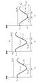
- FIG. 7 illustrates the relationship between the brightness of the unpolarized pixel, the brightness of the polarized pixel, and the angle in the polarization direction (No. 1).
- FIG. 7A illustrates a case where not all the pixels in the polarized pixel block are determined to be invalid pixels.
- the Stokes parameter S 0 is calculated based on the equation (11).
- the coefficient K in the equation (11) is a coefficient that absorbs the sensitivity difference between the polarized pixel and the unpolarized pixel.
- the polarization information generating unit 33 the pixel value I (x, 0), I (x, 90), the Stokes parameters by the least square method using the I (x, 135) and Stokes parameters S 0 S 2, S 1 is calculated.
- FIG. 7B illustrates a case where only unpolarized pixels are determined to be invalid pixels.
- V (x, 135) 0
- the Stokes parameter is calculated without using unpolarized pixels.
- the polarization information generation unit 33 uses the pixel values I (x, 0), I (x, 90), I (x, 135) of polarized pixels that are not invalid pixels and the least squares method from the polarization model equation shown in equation (10).
- the Stokes parameters S 2 , S 1 , and S 0 are calculated by such means.
- FIG. 7C illustrates a case where only one polarized pixel in the polarized pixel block is determined to be an invalid pixel.
- the polarization information generating unit 33 calculates the Stokes parameters S 2, S 1 by the least square method using the I (x, 90) and the Stokes parameters S 0.
- the polarization information generation unit 33 cannot calculate the Stokes parameters S 2 , S 1 , and S 0 when the two polarization pixels in the three polarization pixels of the polarization pixel block are invalid pixels. In this case, the polarization information generation unit 33 may use information indicating that the polarization characteristic cannot be acquired as the polarization information.
- a 2 ⁇ 2 pixel polarized pixel block is composed of two polarized pixels (pixels having polarization directions of “90 °” and “135 °”) and two non-polarized pixels.
- FIG. 8 illustrates the relationship between the brightness of the unpolarized pixel, the brightness of the polarized pixel, and the angle in the polarization direction (No. 2).
- FIG. 8A illustrates a case where not all the pixels in the polarized pixel block are determined to be invalid pixels.
- the Stokes parameter S 0 is calculated based on the equation (11).
- the invalid flag V (x, -1a) indicates the detection result of one unpolarized pixel in the two unpolarized pixels
- the invalid flag V (x, -1b) indicates the detection result of one unpolarized pixel in the two unpolarized pixels. The detection result of the unpolarized pixel of is shown.
- the polarization information generation unit 33 calculates the Stokes parameters S 2 and S 1 by the least squares method or the like using the pixel values I (x, 90), I (x, 135) and the Stokes parameter S 0.
- FIG. 8B illustrates a case where only one unpolarized pixel is determined to be an invalid pixel.
- the pixel used for calculating the Stokes parameter is one unpolarized pixel in the pixel configuration shown in FIG. 4A, as in the case where only one polarized pixel in the polarized pixel block is determined to be an invalid pixel.
- the polarization information generation unit 33 cannot calculate the Stokes parameters S 2 , S 1 , S 0 when it is determined that two unpolarized pixels or one polarized pixel in the polarized pixel block is an invalid pixel.
- FIG. 8C illustrates a case where one polarized pixel in the polarized pixel block is determined to be an invalid pixel.
- the polarization information generation unit 33 may use information indicating that the polarization characteristic cannot be acquired as the polarization information.
- FIG. 9 is a flowchart showing the operation of the image processing unit.
- the image processing unit acquires the captured image.
- the image processing unit generates an image captured by using a polarized image capturing unit composed of polarized pixels and non-polarized pixels, and proceeds to step ST2.
- step ST2 the image processing unit generates a polarized image and a non-polarized image for each polarization direction.
- the image processing unit performs demosaic processing using the captured image, generates a polarized image and a non-polarized image for each polarization direction, and proceeds to step ST3.
- step ST3 the image processing unit detects invalid pixels.
- the image processing unit compares the preset saturation detection threshold Tha, the blackout detection threshold Thb, and the pixel values of the unpolarized pixel and the polarized pixel, and the pixel having a pixel value larger than the saturation detection threshold Tha and the blackout detection threshold.
- a pixel having a pixel value smaller than Thb is detected as an invalid pixel, and the process proceeds to step ST4.
- step ST4 the image processing unit generates polarization information. Based on the pixel value for each polarization direction, the unpolarized pixel value, and the invalid pixel detection result, the image processing unit performs fitting to the polarization model formula using the pixel values of the polarized pixel and the non-polarized pixel that are not invalid pixels. For example, the Stokes parameter is calculated. The image processing unit generates polarization information indicating the calculated Stokes parameter.
- the image processing unit demomosaizes the unpolarized image and the polarized image for each polarization direction from the captured image generated by the polarization imaging unit 20 in which the unpolarized pixel and at least two polarized pixels for each polarization direction are arranged. Generated by the processing unit 31. Further, the image processing unit generates polarization information indicating the polarization characteristics of the subject included in the captured image from the unpolarized image and the polarized image generated by the demosaic processing unit 31 in the polarization information generation unit 33.
- the image processing unit detects invalid pixels from the unpolarized image and the polarized image, and generates polarized information without using the invalid pixels, so that the correct polarized information can be acquired.
- the polarization angles of the polarized pixels are "0 °, 90 °, 135 °" is illustrated, but the polarization angles may be configured not to be orthogonal angles.
- the polarized pixel block may be composed of one unpolarized pixel and three polarized pixels having polarization angles of “0 °, 60 °, 120 °”.
- the polarization information generation unit 33 calculates the Stokes parameter as the polarization information, but the polarization information is not limited to the case where the Stokes parameter is indicated.
- the polarization information generation unit 33 may generate normal information as polarization information.
- the polarization information generation unit 33 calculates the azimuth angle ⁇ based on, for example, the equation (13).
- the polarization information generation unit 33 calculates the zenith angle ⁇ based on the equation (14).
- the parameters A, B, C, and D in the equation (14) are values calculated by the equations (15) to (18), and the degree of polarization ⁇ shown in the equations (15) and (16) is the equation (15). Calculate based on 19). Further, in the equations (15), (17) and (18), the parameters A, B, C and D are calculated using the refractive index n of the subject OB.
- the polarized light imaging unit 20 may generate polarized light information based on the color captured image so that the polarized light imaging unit 20 generates a color captured image.
- FIG. 10 illustrates the configuration of a polarized light imaging unit that generates a color captured image.
- a color mosaic filter 23 is provided on the incident surface of the image sensor 21.
- the color mosaic filter 23 is not limited to the case where it is provided between the image pickup device 21 and the polarizing filter 22, and may be provided on the incident surface of the polarizing filter 22.
- the polarizing filter 22 and the color mosaic filter 23 are configured to provide pixels in each polarization direction with the same color so that the polarization pixels in different polarization directions are not affected by the difference in color. Further, the polarizing filter 22 and the color mosaic filter 23 are configured so that the pixel values of unpolarized pixels can be obtained for each color.
- FIG. 11 illustrates the relationship between the color mosaic filter and the polarizing filter (two polarization directions).
- the polarizing filter 22 has a configuration in which two polarized pixels and two non-polarized pixels having different polarization directions are received in a 2 ⁇ 2 pixel region.
- the color mosaic filter 23 has a configuration in which the 2 ⁇ 2 pixel area is a red (R), green (G), and blue (B) color unit, and the 4 ⁇ 4 pixel area is a red 2 ⁇ 2 pixel area.
- the polarization imaging unit 20 generates pixel values of polarized pixels for each of the two polarization directions and pixel values of unpolarized pixels of either red, green, or blue for each 2 ⁇ 2 pixel region.
- the color mosaic filter 23 has a configuration in which a 2 ⁇ 2 pixel region is set as a color unit of red (R), green (G), and blue (B).
- the polarization filter 22 has a configuration in which two polarized pixels and two unpolarized pixels having different polarization directions are received in a green 2 ⁇ 2 pixel region, and the 4 ⁇ 4 pixel region is a red 2 ⁇ 2 pixel region.
- the polarization imaging unit 20 generates pixel values of unpolarized pixels of either red, green, or blue color and pixel values of polarized pixels in the two polarization directions in green for each 2 ⁇ 2 pixel region. Will be done.
- the polarizing filter 22 has a configuration in which two polarized pixels and two non-polarized pixels having different polarization directions are received in a 2 ⁇ 2 pixel region.
- the color mosaic filter 23 has a configuration in which the 2 ⁇ 2 pixel area is composed of three green (G) pixels and one red (R) or blue (B) pixel, and the 4 ⁇ 4 pixel area is a red pixel. There are two 2 ⁇ 2 pixel areas including, and two 2 ⁇ 2 pixel areas including blue pixels.
- the pixel values of the unpolarized pixels which are green pixels and red pixels or green pixels and blue pixels, and the pixels of the polarized pixels in each of the two polarization directions in green, for each 2 ⁇ 2 pixel region. A value is generated.
- the color mosaic filter 23 covers a 2 ⁇ 2 pixel area with two white (W) pixels and two pixels of any color of red (R), green (G), or blue (B).
- the configuration is as follows.
- the 4x4 pixel area is a 2x2 pixel area including a red pixel, a 2x2 pixel area including a blue pixel, and two 2x2 pixel areas including a green pixel.
- the polarizing filter 22 has a configuration in which white pixels in a 2 ⁇ 2 pixel region including green pixels are polarized pixels having the same polarization direction, and two polarizing pixels in each of the two polarization directions are provided in the 4 ⁇ 4 pixel region. To do.
- the pixel value of the polarized pixel in any of the polarization directions in is generated.
- the color mosaic filter 23 has two white (W) pixels and green (G) and red (R), or two white (W) pixels and green (G) in a 2 ⁇ 2 pixel region. ) And blue (B) pixels.
- the 4x4 pixel area is defined as two 2x2 pixel areas including red pixels and two 2x2 pixel areas including blue pixels.
- the polarizing filter 22 has a configuration in which one white pixel in the 2 ⁇ 2 pixel region is a polarizing pixel, and the 4 ⁇ 4 pixel region is provided with two polarizing pixels in each of the two polarization directions.
- the pixel values of green and red or green and blue unpolarized pixels and the pixel values of polarized pixels in any of the two polarization directions are set for each 2 ⁇ 2 pixel region. Will be generated.
- pixel values of unpolarized pixels of each color and pixel values of polarized pixels for each polarization direction are generated for each 4 ⁇ 4 pixel region.
- FIG. 12 illustrates the relationship between the color mosaic filter and the polarizing filter (three polarization directions).
- the color mosaic filter 23 covers a 2 ⁇ 2 pixel area with two white (W) pixels and two pixels of any color of red (R), green (G), or blue (B).
- the configuration is as follows.
- the 4x4 pixel area is a 2x2 pixel area including a red pixel, a 2x2 pixel area including a blue pixel, and two 2x2 pixel areas including a green pixel.
- the polarizing filter 22 has a configuration in which white pixels in a 2 ⁇ 2 pixel region are used as polarizing pixels in any of the polarization directions, and two polarizing pixels in each of the four polarization directions are provided in the 4 ⁇ 4 pixel region.
- the pixel value of the unpolarized pixel of either red, green, or blue color and the polarized pixel in any of the four polarization directions are used for each 2 ⁇ 2 pixel region. Pixel value is generated.
- the color mosaic filter 23 covers a 2 ⁇ 2 pixel area with two white (W) pixels and green (G) and red (R) or two white (W) pixels and green (G). And blue (B) pixels.
- the 4x4 pixel area is defined as two 2x2 pixel areas including red pixels and two 2x2 pixel areas including blue pixels.
- the polarizing filter 22 has a configuration in which two white pixels in the 2 ⁇ 2 pixel region are polarized pixels having different polarization directions, and in the 4 ⁇ 4 pixel region, two polarizing pixels in each of the four polarization directions are provided.
- the polarized light imaging unit 20 generates pixel values of green and red or green and blue unpolarized pixels and pixel values of polarized pixels in the two polarization directions for each 2 ⁇ 2 pixel region.
- the pixel values of green and red or green and blue unpolarized pixels and the pixel values of polarized pixels in any two of the four polarization directions are used for each 2 ⁇ 2 pixel region. Is generated.
- the color mosaic filter 23 has a configuration in which the 2 ⁇ 2 pixel region is a red (R), green (G), and blue (B) color unit, and the 4 ⁇ 4 pixel region is red. 2 ⁇ 2 pixel area, blue 2 ⁇ 2 pixel area, and green 2 ⁇ 2 pixel area.
- the polarizing filter 22 has a configuration in which four polarizing pixels having different polarization directions are provided in a green 2 ⁇ 2 pixel region. In this case, in the polarized image pickup unit 20, the pixel value of the unpolarized pixel is generated in the red or blue 2 ⁇ 2 pixel region, and the pixel value of the polarized pixel in each polarization direction is generated in the green 2 ⁇ 2 pixel region. Will be done.
- the polarized light imaging unit 20 generates pixel values of unpolarized pixels of each color and pixel values of polarized pixels for each polarization direction for each 4 ⁇ 4 pixel region.
- the demosaic processing unit 31 When the polarized image pickup unit 20 generates a color captured image, the demosaic processing unit 31 generates a non-polarized image for each color component from the color image. Further, the demosaic processing unit 31 generates a polarized image for each polarization direction.
- the polarization information generation unit 33 generates polarization information using a polarized image or a non-polarized image generated by the demosaic processing unit 31. Since the polarized pixels are white or the same color as described above, there is no influence due to the difference in color between the polarized pixels. Therefore, the polarization information can be correctly generated even if the color captured image is used. In addition, in FIG.
- the sensitivity of the green pixel is lower than that of the red pixel and the blue pixel which are non-polarized pixels. Therefore, if the pixel value of the green pixel is corrected according to the decrease in sensitivity of the polarized pixel, the conventional Bayer array demosaic process is performed, which is the same as the case where the pixel of each color component is a non-polarized pixel. A color component image can be generated.
- the image processing unit 30 can generate a non-polarized image for each color by performing integrated processing using pixels of the same color.
- the configuration of the image processing unit is not limited to the configuration shown in FIG.
- the image processing unit 30 is configured corresponding to the pixel configuration of the polarized light imaging unit 20 as described above, the polarized light imaging unit 20 and the image processing unit 30 may be integrally configured.
- the technology according to the present disclosure can be applied to various products.
- the technology according to the present disclosure includes any type of movement such as automobiles, electric vehicles, hybrid electric vehicles, motorcycles, bicycles, personal mobility, airplanes, drones, ships, robots, construction machines, agricultural machines (tractors), and the like. It may be realized as a device mounted on the body. If applied to such a field, accurate polarization information can be acquired, so that the surrounding environment can be accurately grasped in three dimensions based on, for example, polarization information, and fatigue of the driver or operator can be reduced. .. In addition, automatic driving and the like can be performed more safely.
- the technology according to this disclosure can also be applied to the medical field. For example, if it is applied when the captured image of the surgical site is used when performing surgery, it becomes possible to accurately obtain an image without reflection and the three-dimensional shape of the surgical site, which reduces the operator's fatigue and is safe and safe. It becomes possible to perform surgery more reliably.
- the technology related to this disclosure can also be applied to fields such as public services. For example, when an image of a subject is published in a book, a magazine, or the like, unnecessary reflection components or the like can be accurately removed from the image of the subject.
- the series of processes described in the specification can be executed by hardware, software, or a composite configuration of both.
- the program that records the processing sequence is installed in the memory in the computer embedded in the dedicated hardware and executed.
- the program can be installed and executed on a general-purpose computer capable of executing various processes.
- the program can be recorded in advance on a hard disk as a recording medium, an SSD (Solid State Drive), or a ROM (Read Only Memory).
- the program is a flexible disc, CD-ROM (Compact Disc Read Only Memory), MO (Magneto optical) disc, DVD (Digital Versatile Disc), BD (Blu-Ray Disc (registered trademark)), magnetic disc, semiconductor memory card. It can be temporarily or permanently stored (recorded) on a removable recording medium such as an optical disc.
- a removable recording medium can be provided as so-called package software.
- the program may be transferred from the download site to the computer wirelessly or by wire via a network such as a LAN (Local Area Network) or the Internet.
- the computer can receive the program transferred in this way and install it on a recording medium such as a built-in hard disk.
- the image processing device of the present technology can have the following configurations.
- An invalid pixel detection unit that detects saturated pixels and blackened pixels as invalid pixels from an unpolarized image obtained by imaging using a polarized light imaging unit and a plurality of polarized images having different polarization directions.
- An image processing apparatus including a polarization information generating unit that performs polarization information generation processing based on the unpolarized image and the polarized image and switches the polarization information generation processing according to the detection result of the invalid pixel in the invalid pixel detection unit. ..
- the polarization information generation unit includes the pixel of the unpolarized image and other polarized light that is not detected as an invalid pixel.
- the image processing apparatus according to (1) which generates the polarization information using the pixels of the image.
- the plurality of polarized images are three or more polarized images having different polarization directions.
- the image processing apparatus according to (3) wherein the polarization information generation unit generates the polarization information by using the pixels of the unpolarized image and the pixels of at least two or more polarized images that are not detected as invalid pixels.
- the image processing apparatus wherein the at least two or more polarized images are polarized images whose polarization directions are not orthogonal to each other.
- the polarization information generation unit When the invalid pixel is not detected, the polarization information generation unit generates the polarization information using the pixel of the unpolarized image and the pixel of the polarized image, whichever is (1) to (5). Image processing device described in polarized light.
- the invalid pixel detection unit detects the saturated pixel from the unpolarized image and the blackened pixel from the polarized image as the invalid pixel.
- the invalid pixel detection unit detects a pixel having a pixel value larger than a preset saturation detection threshold value as the saturated pixel, and the invalid pixel detection unit detects a pixel having a pixel value smaller than a preset blackout detection threshold value.
- the image processing apparatus according to any one of (1) to (7), which detects as blackened pixels.
- the blackout detection threshold value is set to be larger than the minimum output value of the polarization imaging unit by the first level, and the saturation detection threshold value is the output of the polarization imaging unit by the second level smaller than the first level.
Landscapes
- Engineering & Computer Science (AREA)
- Multimedia (AREA)
- Signal Processing (AREA)
- Physics & Mathematics (AREA)
- Spectroscopy & Molecular Physics (AREA)
- Color Television Image Signal Generators (AREA)
- Studio Devices (AREA)
Abstract
L'invention concerne une unité de détection de pixels invalides 32 qui détecte des pixels invalides à partir d'une image de non polarisation et d'une pluralité d'images de polarisation ayant des directions de polarisation différentes, l'image de non polarisation et les images de polarisation étant obtenues par imagerie à l'aide d'une unité d'imagerie par polarisation 20. Par exemple, l'unité de détection de pixels invalides 32 détecte, à partir de l'image de non polarisation, un pixel saturé ayant une valeur de pixel supérieure à une valeur seuil de détection de saturation prédéfinie, et un pixel écrasé noir ayant une valeur de pixel inférieure à une valeur seuil de détection d'écrasement noir prédéfinie en tant que pixels invalides. Une unité de génération d'informations de polarisation 33 effectue un traitement de génération d'informations de polarisation sur la base de l'image de non polarisation et des images de polarisation, commute le traitement de génération d'informations de polarisation en fonction du résultat de la détection des pixels invalides dans l'unité de détection de pixel invalide 32, et génère des informations de polarisation sans utiliser les pixels invalides, ce qui permet d'acquérir des informations de polarisation correctes.
Priority Applications (4)
| Application Number | Priority Date | Filing Date | Title |
|---|---|---|---|
| US17/789,406 US11758290B2 (en) | 2020-01-09 | 2020-12-18 | Image processing device, image processing method, and image pickup device |
| EP20911393.5A EP4060981A4 (fr) | 2020-01-09 | 2020-12-18 | Dispositif de traitement d'image, procédé de traitement d'image, et dispositif d'imagerie |
| CN202080091404.XA CN114930800B (zh) | 2020-01-09 | 2020-12-18 | 图像处理装置、图像处理方法和成像装置 |
| JP2021569806A JPWO2021140873A1 (fr) | 2020-01-09 | 2020-12-18 |
Applications Claiming Priority (2)
| Application Number | Priority Date | Filing Date | Title |
|---|---|---|---|
| JP2020-002033 | 2020-01-09 | ||
| JP2020002033 | 2020-01-09 |
Publications (1)
| Publication Number | Publication Date |
|---|---|
| WO2021140873A1 true WO2021140873A1 (fr) | 2021-07-15 |
Family
ID=76792845
Family Applications (1)
| Application Number | Title | Priority Date | Filing Date |
|---|---|---|---|
| PCT/JP2020/047434 WO2021140873A1 (fr) | 2020-01-09 | 2020-12-18 | Dispositif de traitement d'image, procédé de traitement d'image, et dispositif d'imagerie |
Country Status (5)
| Country | Link |
|---|---|
| US (1) | US11758290B2 (fr) |
| EP (1) | EP4060981A4 (fr) |
| JP (1) | JPWO2021140873A1 (fr) |
| CN (1) | CN114930800B (fr) |
| WO (1) | WO2021140873A1 (fr) |
Cited By (1)
| Publication number | Priority date | Publication date | Assignee | Title |
|---|---|---|---|---|
| WO2023100467A1 (fr) * | 2021-11-30 | 2023-06-08 | ソニーグループ株式会社 | Dispositif de traitement d'information, procédé de traitement d'information, et programme |
Citations (5)
| Publication number | Priority date | Publication date | Assignee | Title |
|---|---|---|---|---|
| JP2009290895A (ja) | 2007-06-15 | 2009-12-10 | Panasonic Corp | 画像処理装置 |
| WO2017085993A1 (fr) * | 2015-11-19 | 2017-05-26 | ソニー株式会社 | Appareil de traitement d'images, et procédé de traitement d'images |
| JP2017228983A (ja) * | 2016-06-23 | 2017-12-28 | キヤノン株式会社 | 画像処理装置、撮像装置、画像処理方法 |
| JP2018029280A (ja) * | 2016-08-18 | 2018-02-22 | ソニー株式会社 | 撮像装置と撮像方法 |
| WO2018074064A1 (fr) | 2016-10-17 | 2018-04-26 | ソニー株式会社 | Dispositif de traitement d'image, procédé de traitement d'image, et dispositif d'imagerie |
Family Cites Families (12)
| Publication number | Priority date | Publication date | Assignee | Title |
|---|---|---|---|---|
| US8226622B2 (en) * | 2002-12-20 | 2012-07-24 | Kimberly-Clark Worldwide, Inc. | Interlabial absorbent article with soluble adhesive and time-delayed dispersion |
| EP2339534A1 (fr) * | 2009-11-18 | 2011-06-29 | Panasonic Corporation | Compensation de la réflexion spéculaire |
| WO2013047099A1 (fr) * | 2011-09-30 | 2013-04-04 | シャープ株式会社 | Dispositif d'affichage |
| JP6415093B2 (ja) * | 2014-04-25 | 2018-10-31 | キヤノン株式会社 | 画像処理装置、画像処理方法、及びプログラム |
| WO2016136086A1 (fr) * | 2015-02-27 | 2016-09-01 | ソニー株式会社 | Dispositif d'imagerie, dispositif de traitement d'image et procédé de traitement d'image |
| EP3376759B1 (fr) * | 2015-11-10 | 2021-04-14 | Sony Corporation | Dispositif de traitement d'image et procédé de traitement d'image |
| JP6764880B2 (ja) * | 2015-12-11 | 2020-10-07 | 株式会社ニコン | 偏光特性画像計測装置、偏光特性画像計測方法 |
| CN109565546B (zh) * | 2016-08-24 | 2020-12-01 | 索尼公司 | 图像处理设备、信息生成设备以及信息生成方法 |
| EP3509294B1 (fr) * | 2016-08-31 | 2020-08-12 | Sony Corporation | Dispositif de traitement d'image et procédé de traitement d'image |
| WO2019021591A1 (fr) * | 2017-07-28 | 2019-01-31 | ソニー株式会社 | Dispositif de traitement d'images, procédé de traitement d'images, programme, et système de traitement d'images |
| WO2019102698A1 (fr) * | 2017-11-21 | 2019-05-31 | ソニー株式会社 | Dispositif de traitement d'image, procédé de traitement d'image, programme, et dispositif d'imagerie à semi-conducteur |
| DE112021001440T5 (de) * | 2020-03-05 | 2023-02-09 | Fanuc Corporation | Dreidimensionales Messgerät, das aus einem von mehreren Kameras aufgenommenen Bild Positionsinformationen für eine Objektoberfläche erzeugt |
-
2020
- 2020-12-18 US US17/789,406 patent/US11758290B2/en active Active
- 2020-12-18 JP JP2021569806A patent/JPWO2021140873A1/ja active Pending
- 2020-12-18 CN CN202080091404.XA patent/CN114930800B/zh active Active
- 2020-12-18 EP EP20911393.5A patent/EP4060981A4/fr active Pending
- 2020-12-18 WO PCT/JP2020/047434 patent/WO2021140873A1/fr unknown
Patent Citations (5)
| Publication number | Priority date | Publication date | Assignee | Title |
|---|---|---|---|---|
| JP2009290895A (ja) | 2007-06-15 | 2009-12-10 | Panasonic Corp | 画像処理装置 |
| WO2017085993A1 (fr) * | 2015-11-19 | 2017-05-26 | ソニー株式会社 | Appareil de traitement d'images, et procédé de traitement d'images |
| JP2017228983A (ja) * | 2016-06-23 | 2017-12-28 | キヤノン株式会社 | 画像処理装置、撮像装置、画像処理方法 |
| JP2018029280A (ja) * | 2016-08-18 | 2018-02-22 | ソニー株式会社 | 撮像装置と撮像方法 |
| WO2018074064A1 (fr) | 2016-10-17 | 2018-04-26 | ソニー株式会社 | Dispositif de traitement d'image, procédé de traitement d'image, et dispositif d'imagerie |
Non-Patent Citations (1)
| Title |
|---|
| B. GUNTURKJ. GLOTZBACHY. ALTUNBASAKR. SCHAFERR. MERSEREAU: "Demosaicing: Color filter array interpolation", IEEE SIGNAL PROCESSING MAGAZINE, vol. 22, no. 1, January 2005 (2005-01-01) |
Cited By (1)
| Publication number | Priority date | Publication date | Assignee | Title |
|---|---|---|---|---|
| WO2023100467A1 (fr) * | 2021-11-30 | 2023-06-08 | ソニーグループ株式会社 | Dispositif de traitement d'information, procédé de traitement d'information, et programme |
Also Published As
| Publication number | Publication date |
|---|---|
| JPWO2021140873A1 (fr) | 2021-07-15 |
| EP4060981A1 (fr) | 2022-09-21 |
| EP4060981A4 (fr) | 2023-01-18 |
| CN114930800A (zh) | 2022-08-19 |
| US20230053038A1 (en) | 2023-02-16 |
| US11758290B2 (en) | 2023-09-12 |
| CN114930800B (zh) | 2024-05-28 |
Similar Documents
| Publication | Publication Date | Title |
|---|---|---|
| JP6914001B2 (ja) | 撮像素子、イメージセンサ、撮像装置、および情報処理装置 | |
| TWI608259B (zh) | Image pickup device, image sensor, and information processing device | |
| JP7528929B2 (ja) | 撮像装置と画像処理装置および画像処理方法 | |
| JP2011055038A5 (fr) | ||
| TW201215166A (en) | Image capture using luminance and chrominance sensors | |
| WO2018061508A1 (fr) | Élément de capture d'image, dispositif de traitement d'image, procédé de traitement d'image et programme | |
| JP5186517B2 (ja) | 撮像装置 | |
| TW200810566A (en) | Imaging apparatus | |
| US9843782B2 (en) | Interpolation device, storage medium, and method with multi-band color filter and noise reduced reference image | |
| JP4968527B2 (ja) | 撮像装置 | |
| WO2019198287A1 (fr) | Dispositif de traitement d'informations, procédé de traitement d'informations, programme, et dispositif d'étalonnage | |
| WO2012144162A1 (fr) | Appareil de capture d'image tridimensionnelle, unité transparente à la lumière, appareil de traitement d'image et programme | |
| WO2021140873A1 (fr) | Dispositif de traitement d'image, procédé de traitement d'image, et dispositif d'imagerie | |
| US20210235060A1 (en) | Solid-state imaging device, information processing device, information processing method, and calibration method | |
| WO2019078320A1 (fr) | Dispositif de traitement d'informations, procédé de traitement d'informations, dispositif d'imagerie et programme | |
| JP2013057769A (ja) | 固体撮像装置、撮像装置、合焦制御方法、及び、プログラム | |
| CN110392186B (zh) | 减少雾霾影响的成像装置及成像方法 | |
| JP2014155071A5 (fr) | ||
| JP2008042227A (ja) | 撮像装置 | |
| TW202335271A (zh) | 具有晶載包藏偵測之影像感測器及其方法 | |
| WO2022113568A1 (fr) | Dispositif de traitement d'image, procédé de traitement d'image et programme | |
| WO2022107530A1 (fr) | Dispositif de traitement de signal, procédé de traitement de signal et programme | |
| JP2014011754A (ja) | 制御装置、制御方法、及びプログラム | |
| WO2021024577A1 (fr) | Dispositif de commande d'imagerie, procédé de commande d'imagerie, programme et dispositif d'imagerie | |
| WO2023089956A1 (fr) | Dispositif de traitement d'image, procédé de traitement d'image et programme |
Legal Events
| Date | Code | Title | Description |
|---|---|---|---|
| 121 | Ep: the epo has been informed by wipo that ep was designated in this application |
Ref document number: 20911393 Country of ref document: EP Kind code of ref document: A1 |
|
| ENP | Entry into the national phase |
Ref document number: 2021569806 Country of ref document: JP Kind code of ref document: A |
|
| ENP | Entry into the national phase |
Ref document number: 2020911393 Country of ref document: EP Effective date: 20220618 |
|
| NENP | Non-entry into the national phase |
Ref country code: DE |