WO2021140775A1 - Ceramic structure - Google Patents
Ceramic structure Download PDFInfo
- Publication number
- WO2021140775A1 WO2021140775A1 PCT/JP2020/044085 JP2020044085W WO2021140775A1 WO 2021140775 A1 WO2021140775 A1 WO 2021140775A1 JP 2020044085 W JP2020044085 W JP 2020044085W WO 2021140775 A1 WO2021140775 A1 WO 2021140775A1
- Authority
- WO
- WIPO (PCT)
- Prior art keywords
- truss structure
- ceramic
- truss
- ceramic structure
- degrees
- Prior art date
Links
Images


Classifications
-
- F—MECHANICAL ENGINEERING; LIGHTING; HEATING; WEAPONS; BLASTING
- F28—HEAT EXCHANGE IN GENERAL
- F28F—DETAILS OF HEAT-EXCHANGE AND HEAT-TRANSFER APPARATUS, OF GENERAL APPLICATION
- F28F3/00—Plate-like or laminated elements; Assemblies of plate-like or laminated elements
- F28F3/12—Elements constructed in the shape of a hollow panel, e.g. with channels
-
- C—CHEMISTRY; METALLURGY
- C04—CEMENTS; CONCRETE; ARTIFICIAL STONE; CERAMICS; REFRACTORIES
- C04B—LIME, MAGNESIA; SLAG; CEMENTS; COMPOSITIONS THEREOF, e.g. MORTARS, CONCRETE OR LIKE BUILDING MATERIALS; ARTIFICIAL STONE; CERAMICS; REFRACTORIES; TREATMENT OF NATURAL STONE
- C04B38/00—Porous mortars, concrete, artificial stone or ceramic ware; Preparation thereof
- C04B38/008—Bodies obtained by assembling separate elements having such a configuration that the final product is porous or by spirally winding one or more corrugated sheets
- C04B38/0083—Bodies obtained by assembling separate elements having such a configuration that the final product is porous or by spirally winding one or more corrugated sheets from one or more corrugated sheets or sheets bearing protrusions by winding or stacking
-
- F—MECHANICAL ENGINEERING; LIGHTING; HEATING; WEAPONS; BLASTING
- F28—HEAT EXCHANGE IN GENERAL
- F28D—HEAT-EXCHANGE APPARATUS, NOT PROVIDED FOR IN ANOTHER SUBCLASS, IN WHICH THE HEAT-EXCHANGE MEDIA DO NOT COME INTO DIRECT CONTACT
- F28D9/00—Heat-exchange apparatus having stationary plate-like or laminated conduit assemblies for both heat-exchange media, the media being in contact with different sides of a conduit wall
- F28D9/0031—Heat-exchange apparatus having stationary plate-like or laminated conduit assemblies for both heat-exchange media, the media being in contact with different sides of a conduit wall the conduits for one heat-exchange medium being formed by paired plates touching each other
- F28D9/0037—Heat-exchange apparatus having stationary plate-like or laminated conduit assemblies for both heat-exchange media, the media being in contact with different sides of a conduit wall the conduits for one heat-exchange medium being formed by paired plates touching each other the conduits for the other heat-exchange medium also being formed by paired plates touching each other
-
- F—MECHANICAL ENGINEERING; LIGHTING; HEATING; WEAPONS; BLASTING
- F28—HEAT EXCHANGE IN GENERAL
- F28F—DETAILS OF HEAT-EXCHANGE AND HEAT-TRANSFER APPARATUS, OF GENERAL APPLICATION
- F28F21/00—Constructions of heat-exchange apparatus characterised by the selection of particular materials
- F28F21/04—Constructions of heat-exchange apparatus characterised by the selection of particular materials of ceramic; of concrete; of natural stone
-
- F—MECHANICAL ENGINEERING; LIGHTING; HEATING; WEAPONS; BLASTING
- F28—HEAT EXCHANGE IN GENERAL
- F28F—DETAILS OF HEAT-EXCHANGE AND HEAT-TRANSFER APPARATUS, OF GENERAL APPLICATION
- F28F3/00—Plate-like or laminated elements; Assemblies of plate-like or laminated elements
- F28F3/02—Elements or assemblies thereof with means for increasing heat-transfer area, e.g. with fins, with recesses, with corrugations
- F28F3/04—Elements or assemblies thereof with means for increasing heat-transfer area, e.g. with fins, with recesses, with corrugations the means being integral with the element
-
- F—MECHANICAL ENGINEERING; LIGHTING; HEATING; WEAPONS; BLASTING
- F28—HEAT EXCHANGE IN GENERAL
- F28F—DETAILS OF HEAT-EXCHANGE AND HEAT-TRANSFER APPARATUS, OF GENERAL APPLICATION
- F28F3/00—Plate-like or laminated elements; Assemblies of plate-like or laminated elements
- F28F3/08—Elements constructed for building-up into stacks, e.g. capable of being taken apart for cleaning
Definitions
- Patent Document 1 discloses a ceramic structure having a truss structure (honeycomb structure).
- the ceramic structure having a truss structure is characterized by being lightweight and having high strength.
- FIG. 8 shows a schematic view of the ceramic structure of Patent Document 1.
- a partition wall 422 extending in one direction (Y direction) is provided between the surface layer 402 and the back layer 404.
- the truss structure is composed of the surface layer 402, the back layer 404, and the partition wall 422.
- a plurality of through holes 424 extending in the Y direction are formed by the surface layer 402, the back layer 404, and the partition wall 422.
- the ceramic structure of Patent Document 1 is an integrally molded product and is manufactured by extrusion molding.
- the ceramic structure 400 is reduced in weight by providing a through hole 424. Further, since the ceramic structure 400 has a truss structure, high strength is also realized.
- the ceramic structure 400 is higher in the direction in which the partition wall 422 (through hole 424) extends (Y-axis direction) and in the thickness direction (Z-axis direction) orthogonal to the surface layer 402 (back layer 404). It is strength. However, the ceramic structure 400 is relatively weak against shearing forces in the X-axis direction (directions orthogonal to the Y-axis direction and the Z-axis direction), particularly in the X-axis direction. The ceramic structure 400 has relatively low strength in a specific direction, and thus has low versatility (uses are limited). It is an object of the present specification to provide a technique for realizing a highly versatile ceramic structure.
- the ceramic structure disclosed in the present specification includes a first truss structure made of ceramics provided with a plurality of through holes extending in a first direction orthogonal to the thickness direction, and a first truss structure orthogonal to the thickness direction and in the first direction. May include a second truss structure made of ceramics provided with a plurality of through holes extending in different second directions. Further, the first truss structure and the second truss structure may be laminated in the thickness direction.
- the ceramic structure disclosed in the present specification is an integrally molded product in which a plurality of ceramic truss structures provided with a plurality of through holes extending in one direction orthogonal to the thickness direction are laminated in the thickness direction. It may be a ceramic structure of. In this ceramic structure, the truss structures may be laminated so that the through holes extend in two or more directions orthogonal to the thickness direction.
- the perspective view of the ceramic structure of 1st Example is shown.
- a partially enlarged view of the truss structure is shown.
- the concentration distribution of specific elements contained in the skeleton constituting the truss structure is shown.
- the figure explaining the positional relationship between the 1st through hole and the 2nd through hole is shown.
- the perspective view of the ceramic structure of 2nd Example is shown.
- the figure explaining the positional relationship of the 1st to 3rd through holes is shown.
- the perspective view of the ceramic structure of 3rd Example is shown.
- the perspective view of the ceramic structure of the 3rd Example observed from the angle different from FIG. 7A is shown.
- the figure explaining the feature of the conventional truss structure is shown.
- a plurality of ceramic truss structures provided with a plurality of through holes extending in one direction orthogonal to the thickness direction may be laminated in the thickness direction.
- the ceramic structure may be an integrally molded product in which each truss structure is integrated.
- each truss structure is integrally formed at the time of the molded body before firing, and by firing the integrally formed molded body, each truss structure after firing is integrated. It means that it is configured as a target.
- the truss structures may be laminated so that the through holes extend in two or more directions orthogonal to the thickness direction.
- this ceramic structure is at least orthogonal to the first truss structure made of ceramics provided with a plurality of through holes extending in the first direction orthogonal to the thickness direction, and is orthogonal to the thickness direction and is the first direction. It may include a second truss structure made of ceramics provided with a plurality of through holes extending in different second directions. Further, a ceramic third truss structure (third direction ⁇ first and second directions) provided with a through hole extending in the third direction, and a ceramic material having a through hole extending in the fourth direction. A fourth truss structure (fourth direction ⁇ first, second, third direction) and the like may be provided.
- Each truss structure may be provided with a partition wall that connects the surface layer, the back layer, the surface layer and the back layer, and extends in one direction orthogonal to the thickness direction.
- a plurality of through holes may be formed by the surface layer, the back layer, and the partition wall.
- the surface layer of the specific truss structure may also serve as the back layer of the truss structure laminated on the surface layer of the truss structure in the thickness direction. That is, when the second truss structure is laminated on the surface layer of the first truss structure, the surface layer of the first truss structure may be the back layer of the second truss structure.
- the front surface and the back surface of the ceramic structure may be flat surfaces.
- the partition wall defining the wall surface of the through hole extends in two or more directions orthogonal to the thickness direction. Therefore, the strength of the specific truss structure can be supplemented by the force applied from the direction in which the strength is relatively weak. Specifically, focusing on a specific truss structure, the specific truss structure is added from a specific direction (hereinafter referred to as a lateral direction) orthogonal to the thickness direction and the direction in which the through hole (bulkhead) extends. Relatively weak against force.
- the ceramic structure described above resists the force applied from the lateral direction by other truss structures laminated on the specific truss structure, it is possible to improve the strength balance of the ceramic structure in the surface direction. it can.
- the above-mentioned ceramic structure can be used for various purposes by solving the problem of the conventional ceramic structure that it is "relatively weak against a force from a specific direction". That is, the ceramic structure is highly versatile.
- truss structures having through holes extending in the same direction in the thickness direction may be continuously laminated.
- first truss structures having through holes extending in the first direction in the thickness direction may be continuously laminated. That is, as long as the truss structures are laminated so that the through holes extend in at least two directions orthogonal to the thickness direction, the stacking order of the truss structures can be arbitrarily changed.
- other truss structures having different through hole extending directions may be laminated on both sides of the specific truss structure in the thickness direction.
- the second truss structure having the through holes extending in the second direction different from the first direction is laminated on both sides of the first truss structure having the through holes extending in the first direction.
- the ceramic structure has through holes extending in at least two directions (first direction and second direction).
- first direction and the second direction are non-parallel
- the strength balance in the surface direction of the ceramic structure can be improved.
- the angle (acute angle) formed by the first direction and the second direction is 10 degrees or more and 90 degrees or less
- the first truss structure and the second truss structure complement each other in strength
- the strength balance in the plane direction is good.
- the angle (acute angle) formed by the first direction and the second direction is 80 degrees or more and 90 degrees or less, that is, if the first direction and the second direction are substantially orthogonal to each other
- the strength balance in the surface direction is further improved. Can be improved.
- the ceramics structure has through holes extending in three or more different directions, the above relationship may be satisfied in any two directions.
- the ceramics structure has a first truss structure having a first through hole extending in the first direction, a second truss structure having a second through hole extending in the second direction ( ⁇ the first direction), and a third direction.
- a ceramics structure having a third truss structure having a third through hole extending in ( ⁇ 1st direction, 2nd direction) the angle ⁇ 1 formed by the 1st direction and the 3rd direction, and the 2nd and 3rd directions are
- the angle ⁇ 2 formed and the angle ⁇ 3 formed by the first direction and the second direction are set, the following equations (1) and (2) may be satisfied.
- At least the angle ⁇ 3 formed by the first through hole and the second through hole can be set to 60 degrees or more, and they are lateral to each other.
- Each truss structure constituting the ceramic structure may be made of the same material.
- the material of each truss structure may be SiC quality, mullite quality, ZrO2 quality, or SiC-SiC quality.
- Si-SiC quality means a material containing SiC particles as a main component and metallic Si between the SiC particles.
- the skeleton constituting the truss structure may have substantially no pores.
- the porosity of the skeleton can be measured in accordance with JIS R 1655 (a method for testing the porosity distribution of a molded body by a mercury press-fitting method for fine ceramics).
- the ceramic structure disclosed in the present specification is an integrally molded product in which each truss structure is integrated, the through holes formed in each truss structure are formed in the thickness direction. It extends in two or more orthogonal directions.
- a ceramic structure for example, after forming a desired shape with a flammable material, an intermediate is formed by impregnating this material with a ceramic material (ceramic slurry), and the intermediate is fired.
- flammable materials include paper, cloth, and resin.
- the material components of the porous material tend to remain inside the skeleton as compared with the surface layer portion of the skeleton constituting each truss structure.
- At least one element of carbon and calcium is contained inside the skeleton as compared with the surface layer portion of the skeleton constituting each truss structure. May be included in large quantities.
- the ceramic structure each truss structure
- the main component more than 50 wt% of the whole
- the surface layer of the skeleton is SiC and the rest is metallic Si
- the main component may be metallic Si and the balance may be carbon and / or calcium.
- the ceramic structure disclosed in the present specification truss structures having a plurality of through holes are laminated in the thickness direction. Therefore, the weight of the ceramic structure can be reduced, and the heat insulating property in the thickness direction can be increased (the thermal conductivity between the front and back surfaces can be reduced). Further, since the truss structures are laminated so that the through holes extend in a plurality of directions, the strength balance in the surface direction can be improved. Taking advantage of these characteristics, the ceramic structure can be suitably used as a heat insulating member (or a constituent member of the heat insulating member).
- the ceramic structure can be suitably used as a heat exchange member of a heat exchanger by taking advantage of the feature that the through holes extend in a plurality of directions even though it is an integrally molded product.
- the through hole of the first truss structure is used as a flow path for passing the first heat medium
- the through hole of the second truss structure is used as a flow path for passing the second heat medium. By using it as a path, heat exchange between the first heat medium and the second heat medium can be performed.
- the material of the ceramic structure is preferably SiC or SiC material having high thermal conductivity.
- FIG. 1 shows a substantially cubic ceramic structure 100
- the ceramic structure 100 has a thickness (Z-axis) of the front surface 2 and the back surface 4 (length in the X-axis direction and length in the Y-axis direction). In some cases, it is a flat plate that is much larger than the length in the direction.
- the ceramic structure 100 includes a first truss structure 10 and a second truss structure 20.
- the first truss structure 10 and the second truss structure 20 are alternately laminated in the thickness direction (Z-axis direction). That is, except for the truss structure located at the end in the thickness direction, the second truss structure 20 is laminated on both sides of the first truss structure 10, and the first truss structure 10 is laminated on both sides of the second truss structure 20.
- the first truss structure 10 and the second truss structure 20 have substantially the same structure except for the direction in which the through hole extends.
- the first truss structure 10 has a plurality of first through holes 14 extending in the Y-axis direction (an example of the first direction).
- the first through hole 14 is defined by a surface layer of the first truss structure 10, a back layer, and a partition wall 12 provided between the surface layer and the back layer.
- the second truss structure 20 has a plurality of second through holes 24 extending in the X-axis direction (an example of the second direction) orthogonal to the Y-axis direction and the Z-axis direction.
- the third through hole 24 is defined by a surface layer of the second truss structure 20, a back layer, and a partition wall 22 provided between the surface layer and the back layer.
- each truss structure 10 and 20 partition walls 12 and 22 are connected to the surface layer 16 and the back layer 18, and a plurality of through holes 14 (24) are formed.
- the partition wall 12 is connected to the surface layer 16 and the back layer 18 in an inclined state to realize a truss structure (first truss structure 10).
- the surface layer 16, the back layer 18, and the partition wall 12 are integrally molded, and there is no clear boundary between the surface layer 16 and the partition wall 12, and the back layer 18 and the partition wall 12.
- the ceramic structure 100 shown in FIG. 1 is an integrally molded product in which the first truss structure 10 and the second truss structure 20 are integrated.
- the surface layer 16 is the surface 2 of the ceramic structure 100.
- the back layer 18 is the back surface 4 of the ceramic structure 100.
- the ceramic structure 100 is manufactured by forming an intermediate body in which a flammable base material such as paper is impregnated with a SiC slurry, and then firing the metal Si in contact with the metal Si. Therefore, the surface portion of the skeleton (surface layer 16, back layer 18, partition wall 12) constituting the ceramic structure 100 is mainly composed of SiC and the rest is metallic Si. The inside of the skeleton is mainly composed of metallic Si and the rest is elements (carbon and / or calcium) contained in the base material. The open porosity on the surface of the skeleton is 1% or less.
- FIG. 3 shows the concentration distribution of the components of the base material contained in the skeleton constituting the ceramic structure 100.
- the horizontal axis of the graph indicates the thickness of the skeleton (for example, the thickness 31 of the surface layer 16 and the thickness 32 of the partition wall 12 shown in FIG. 2) in terms of the distance (%) from one end to the other end.
- the vertical axis shows the ratio of elements (C, Ca) derived from the base material.
- the surface portion of the aggregate contains almost no “C” or “Ca”. "C” and "Ca” begin to appear after a predetermined depth has passed from the surface of the skeleton and increase toward the center of the skeleton.
- the first through hole 14 extends in the Y-axis direction
- the second through hole 24 extends in the X-axis direction. That is, in the ceramic structure 100, the angle formed by the direction in which the first through hole 14 extends (first direction) and the direction in which the second direction extends (second direction) is 90 degrees. However, the angle formed by the first direction and the second direction does not have to be 90 degrees. As shown in FIG. 4, the angle formed by the second direction (direction 24 in which the second through hole extends) with respect to the first direction (direction in which the first through hole 14 extends) is in the range ⁇ 1 of 10 degrees or more and 90 degrees or less.
- the strengths of the first truss structure 10 and the second truss structure 20 can be complemented with each other. If the angle formed by the second direction with respect to the first direction is in the range ⁇ 2 (that is, substantially right angle) of 80 degrees or more and 90 degrees or less, the first truss structure 10 and the second truss structure 20 are mutually. The reinforcing effect is maximized.
- truss structures having through holes extending in the same direction in the thickness direction may be continuously laminated. That is, the first truss structure 10 (or the second truss structure 20) may be continuously laminated twice or more in the thickness direction. In this case, the thickness and / or the through-hole size of the first truss structure 10 (or the second truss structure 20) to be continuously laminated may be different.
- the ceramic structure 200 will be described with reference to FIG.
- the ceramic structure 200 is a modification of the ceramic structure 100, and a third truss structure 30 is provided between the first truss structure 10 and the second truss structure 20.
- the same structure as that of the ceramic structure 100 may be omitted by assigning the same reference number as the reference number assigned to the ceramic structure 100.
- the third truss structure 30 includes a plurality of third through holes 34 extending in the third direction.
- the direction in which the third through hole 34 extends (third direction) is the direction in which the first through hole 14 extends (first direction: Y-axis direction) and the direction in which the second through hole 24 extends (second direction: X-axis direction).
- first direction first direction: Y-axis direction
- second direction X-axis direction
- the angle formed by the third through hole 34 and the first through hole 14 is 45 degrees
- the angle formed by the third through hole 34 and the second through hole 24 is also 45 degrees.
- the stacking order of the truss structures 10, 20, and 30 can be changed.
- truss structures having through holes extending in the same direction in the thickness direction may be continuously laminated.
- the first truss structures 10 may be continuously laminated in the thickness direction.
- the thickness and / or through-hole size of the truss structures 10 that are continuously laminated may be different.
- the direction in which the first through hole 14 extends (first direction), the direction in which the second through hole 24 extends (second direction), and the direction in which the third through hole 34 extends (third direction).
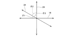
- the total angle ( ⁇ 1 + ⁇ 2 + ⁇ 3) of the angle ⁇ 1 formed by the first direction and the third direction, the angle ⁇ 2 formed by the second direction and the third direction, and the angle ⁇ 3 formed by the first direction and the second direction is 180 degrees. Adjust each direction so that. Further, as shown in FIG. 6, the angle ⁇ 1 is adjusted to 50 degrees or less, and the angle ⁇ 2 is adjusted to 70 degrees or less. The angle ⁇ 3 is adjusted to 60 degrees or more.
- the directions in which the through holes 14, 24 and 34 extend are adjusted so as to satisfy the following equations (1) and (2).
- FIG. 7B shows a perspective view (showing the surface 50) observed from the side opposite to that of FIG. 7A.
- the ceramic structure 300 is a modification of the ceramic structures 100 and 200, and like the ceramic structure 200, the third truss structure 330 is provided between the first truss structure 310 and the second truss structure 320. Has been done.
- the same configuration as the ceramic structures 100 and 200 may be omitted by assigning the same reference number as the reference number attached to the ceramic structures 100 and 200 and the last two digits. ..
- the ceramic structure 300 has an equilateral triangle shape on the front surface 302 and the back surface 304.
- the ceramic structure 300 includes truss structures 310, 320, and 330 in which the through holes extend in different directions.
- the angle formed by the direction in which the through hole 14 of the first truss structure 310 extends (first direction) and the direction in which the through hole 24 of the second truss structure 320 extends (second direction) is 60 degrees.
- the angle formed by the direction in which the through hole 14 of the first truss structure 310 extends (first direction) and the direction in which the through hole 34 of the third truss structure 330 extends (third direction) is also 60 degrees. Therefore, the angle formed by the second direction and the third direction is also 60 degrees.
- the ceramic structure 300 satisfies the above formula (2).
- the through holes can be arranged so as to be orthogonal to the side surface of the ceramic structure 300. Therefore, for example, when the ceramic structure 300 is used as a heat exchange member for circulating a fluid (heat medium) through each through hole, the movement resistance of the fluid can be reduced.
- First truss structure 14 Through hole of the first truss structure 20: Second truss structure 24: Through hole of the second truss structure 100: Ceramic structure
Abstract
This ceramic structure comprises: ceramic first truss structures provided with a plurality of through-holes that extend in a first direction orthogonal to the thickness direction; and ceramic second truss structures provided with a plurality of through-holes that extend in a second direction that is orthogonal to the thickness direction, the second direction being different from the first direction. In this ceramic structure, the first truss structures and the second truss structures are stacked in the thickness direction.
Description
本出願は、2020年1月6日に出願された日本国特許出願第2020-000554号に基づく優先権を主張する。その出願の全ての内容は、この明細書中に参照により援用されている。本明細書は、セラミックス構造体に関する技術を開示する。特に、トラス構造を有するセラミックス構造体に関する技術を開示する。
This application claims priority based on Japanese Patent Application No. 2020-000554 filed on January 6, 2020. The entire contents of that application are incorporated herein by reference. This specification discloses techniques relating to ceramic structures. In particular, a technique relating to a ceramic structure having a truss structure will be disclosed.
国際公開WO2018/047784号(以下、特許文献1と称する)に、トラス構造(ハニカム構造)を有するセラミックス構造体が開示されている。トラス構造を有するセラミックス構造体は、軽量でありながら高強度であるという特徴を備えている。
International Publication WO 2018/047784 (hereinafter referred to as Patent Document 1) discloses a ceramic structure having a truss structure (honeycomb structure). The ceramic structure having a truss structure is characterized by being lightweight and having high strength.
図8に、特許文献1のセラミックス構造体の概略図を示している。図8に示すように、セラミックス構造体400では、表層402と裏層404の間に、一方向(Y方向)に伸びる隔壁422が設けられている。表層402と裏層404と隔壁422によって、トラス構造が構成されている。また、表層402と裏層404と隔壁422によって、Y方向伸びる複数の貫通孔424が形成されている。なお、特許文献1のセラミックス構造体は、一体成型品であり、押出成型によって製造されている。セラミックス構造体400は、貫通孔424を設けることによって軽量化を実現している。また、セラミックス構造体400は、トラス構造を有しているので、高強度化も実現している。具体的には、セラミックス構造体400は、隔壁422(貫通孔424)が伸びる方向(Y軸方向)、及び、表層402(裏層404)に直交する厚み方向(Z軸方向)に対して高強度である。しかしながら、セラミックス構造体400は、X軸方向(Y軸方向及びZ軸方向に直交する方向)、特に、X軸方向の剪断力に対して比較的弱い。セラミックス構造体400は、特定の方向における強度が比較的弱くなるので、汎用性が低い(用途が限定的である)。本明細書は、汎用性の高いセラミックス構造体を実現する技術を提供することを目的とする。
FIG. 8 shows a schematic view of the ceramic structure of Patent Document 1. As shown in FIG. 8, in the ceramic structure 400, a partition wall 422 extending in one direction (Y direction) is provided between the surface layer 402 and the back layer 404. The truss structure is composed of the surface layer 402, the back layer 404, and the partition wall 422. Further, a plurality of through holes 424 extending in the Y direction are formed by the surface layer 402, the back layer 404, and the partition wall 422. The ceramic structure of Patent Document 1 is an integrally molded product and is manufactured by extrusion molding. The ceramic structure 400 is reduced in weight by providing a through hole 424. Further, since the ceramic structure 400 has a truss structure, high strength is also realized. Specifically, the ceramic structure 400 is higher in the direction in which the partition wall 422 (through hole 424) extends (Y-axis direction) and in the thickness direction (Z-axis direction) orthogonal to the surface layer 402 (back layer 404). It is strength. However, the ceramic structure 400 is relatively weak against shearing forces in the X-axis direction (directions orthogonal to the Y-axis direction and the Z-axis direction), particularly in the X-axis direction. The ceramic structure 400 has relatively low strength in a specific direction, and thus has low versatility (uses are limited). It is an object of the present specification to provide a technique for realizing a highly versatile ceramic structure.
本明細書で開示するセラミックス構造体は、厚み方向に直交する第1方向に伸びる複数の貫通孔が設けられているセラミックス製の第1トラス構造体と、厚み方向に直交するとともに第1方向とは異なる第2方向に伸びる複数の貫通孔が設けられているセラミックス製の第2トラス構造体を備えていてよい。また、第1トラス構造体と第2トラス構造体が、厚み方向に積層されていてよい。
The ceramic structure disclosed in the present specification includes a first truss structure made of ceramics provided with a plurality of through holes extending in a first direction orthogonal to the thickness direction, and a first truss structure orthogonal to the thickness direction and in the first direction. May include a second truss structure made of ceramics provided with a plurality of through holes extending in different second directions. Further, the first truss structure and the second truss structure may be laminated in the thickness direction.
また、本明細書で開示するセラミックス構造体は、厚み方向に直交する一方向に伸びる複数の貫通孔が設けられているセラミックス製のトラス構造体が、厚み方向に複数積層されている一体成型品のセラミックス構造体であってよい。このセラミックス構造体では、各トラス構造体が、上記貫通孔が厚み方向に直交する二方向以上に伸びるように積層されていてよい。
Further, the ceramic structure disclosed in the present specification is an integrally molded product in which a plurality of ceramic truss structures provided with a plurality of through holes extending in one direction orthogonal to the thickness direction are laminated in the thickness direction. It may be a ceramic structure of. In this ceramic structure, the truss structures may be laminated so that the through holes extend in two or more directions orthogonal to the thickness direction.
本明細書で開示するセラミックス構造体は、厚み方向に直交する一方向に伸びる複数の貫通孔が設けられているセラミックス製のトラス構造体が、厚み方向に複数積層されていてよい。セラミックス構造体は、各トラス構造体が一体となった一体成型品であってよい。一体成型品とは、焼成前の成形体の時点で各トラス構造体が一体的に構成されており、一体的に構成された成形体を焼成することにより、焼成後の各トラス構成体が一体的に構成されていることを意味する。また、各トラス構造体が、貫通孔が厚み方向に直交する二方向以上に伸びるように積層されていてよい。すなわち、このセラミックス構造体は、少なくとも、厚み方向に直交する第1方向に伸びる複数の貫通孔が設けられているセラミックス製の第1トラス構造体と、厚み方向に直交するとともに第1方向とは異なる第2方向に伸びる複数の貫通孔が設けられているセラミックス製の第2トラス構造体を備えていてよい。また、第3方向に伸びる貫通孔が設けられているセラミックス製の第3トラス構造体(第3方向≠第1,第2方向)、第4方向に伸びる貫通孔が設けられているセラミックス製の第4トラス構造体(第4方向≠第1,第2,第3方向)等を備えていてもよい。
In the ceramic structure disclosed in the present specification, a plurality of ceramic truss structures provided with a plurality of through holes extending in one direction orthogonal to the thickness direction may be laminated in the thickness direction. The ceramic structure may be an integrally molded product in which each truss structure is integrated. In the integrally molded product, each truss structure is integrally formed at the time of the molded body before firing, and by firing the integrally formed molded body, each truss structure after firing is integrated. It means that it is configured as a target. Further, the truss structures may be laminated so that the through holes extend in two or more directions orthogonal to the thickness direction. That is, this ceramic structure is at least orthogonal to the first truss structure made of ceramics provided with a plurality of through holes extending in the first direction orthogonal to the thickness direction, and is orthogonal to the thickness direction and is the first direction. It may include a second truss structure made of ceramics provided with a plurality of through holes extending in different second directions. Further, a ceramic third truss structure (third direction ≠ first and second directions) provided with a through hole extending in the third direction, and a ceramic material having a through hole extending in the fourth direction. A fourth truss structure (fourth direction ≠ first, second, third direction) and the like may be provided.
各トラス構造体は、表層と、裏層と、表層と裏層を接続しているとともに厚み方向に直交する一方向に伸びる隔壁を備えていてよい。表層と裏層と隔壁によって、複数の貫通孔が形成されていてよい。特定のトラス構造体の表層は、厚み方向においてそのトラス構造体の表層上に積層されているトラス構造体の裏層を兼ねていてよい。すなわち、第1トラス構造体の表層上に第2トラス構造体が積層されている場合、第1トラス構造体の表層が第2トラス構造体の裏層であってよい。なお、セラミックス構造体の表面及び裏面は、平坦面であってよい。
Each truss structure may be provided with a partition wall that connects the surface layer, the back layer, the surface layer and the back layer, and extends in one direction orthogonal to the thickness direction. A plurality of through holes may be formed by the surface layer, the back layer, and the partition wall. The surface layer of the specific truss structure may also serve as the back layer of the truss structure laminated on the surface layer of the truss structure in the thickness direction. That is, when the second truss structure is laminated on the surface layer of the first truss structure, the surface layer of the first truss structure may be the back layer of the second truss structure. The front surface and the back surface of the ceramic structure may be flat surfaces.
上記したセラミックス構造体は、貫通孔の壁面を画定する隔壁が、厚み方向に直交する二方向以上に伸びている。そのため、特定のトラス構造体において強度が比較的弱い方向から加わる力に対して、他のトラス構造体が強度を補うことができる。具体的には、特定のトラス構造体に着目すると、その特定のトラス構造体は、厚み方向に直交するとともに貫通孔(隔壁)が伸びる方向に直交する特定方向(以下、横方向という)から加わる力に対して比較的弱い。しかしながら、上記したセラミックス構造体は、特定のトラス構造体上に積層されている他のトラス構造体が横方向から加わる力に抗するので、セラミックス構造体の面方向の強度バランスを改善することができる。その結果、上記したセラミックス構造体は、「特定方向からの力に比較的弱い」という従来のセラミックス構造体の課題が解決され、種々の目的で用いることができる。すなわち、上記セラミックス構造体は汎用性が高い。
In the ceramic structure described above, the partition wall defining the wall surface of the through hole extends in two or more directions orthogonal to the thickness direction. Therefore, the strength of the specific truss structure can be supplemented by the force applied from the direction in which the strength is relatively weak. Specifically, focusing on a specific truss structure, the specific truss structure is added from a specific direction (hereinafter referred to as a lateral direction) orthogonal to the thickness direction and the direction in which the through hole (bulkhead) extends. Relatively weak against force. However, since the ceramic structure described above resists the force applied from the lateral direction by other truss structures laminated on the specific truss structure, it is possible to improve the strength balance of the ceramic structure in the surface direction. it can. As a result, the above-mentioned ceramic structure can be used for various purposes by solving the problem of the conventional ceramic structure that it is "relatively weak against a force from a specific direction". That is, the ceramic structure is highly versatile.
なお、厚み方向において、同じ方向に伸びる貫通孔を有するトラス構造体が連続して積層されていてもよい。例えば、厚み方向において、第1方向に伸びる貫通孔を有する第1トラス構造体が、連続して積層されていてもよい。すなわち、厚み方向に直交する方向のうちの少なくとも二方向に貫通孔が伸びるように各トラス構造体が積層されていれば、各トラス構造体の積層順は任意に変更することができる。但し、特定のトラス構造体における横方向の強度を補うという観点より、厚み方向において、特定のトラス構造体の両側に、貫通孔が伸びる方向が異なる他のトラス構造体が積層されていることが好ましい。すなわち、第1方向に伸びる貫通孔を有する第1トラス構造体の両側に、第1方向とは異なる第2方向に伸びる貫通孔を有する第2トラス構造体が積層されていることが好ましい。
Note that truss structures having through holes extending in the same direction in the thickness direction may be continuously laminated. For example, first truss structures having through holes extending in the first direction in the thickness direction may be continuously laminated. That is, as long as the truss structures are laminated so that the through holes extend in at least two directions orthogonal to the thickness direction, the stacking order of the truss structures can be arbitrarily changed. However, from the viewpoint of supplementing the lateral strength of the specific truss structure, other truss structures having different through hole extending directions may be laminated on both sides of the specific truss structure in the thickness direction. preferable. That is, it is preferable that the second truss structure having the through holes extending in the second direction different from the first direction is laminated on both sides of the first truss structure having the through holes extending in the first direction.
上記したように、セラミックス構造体は、少なくとも二方向(第1方向と第2方向)に伸びる貫通孔を有している。第1方向と第2方向が非平行であれば、セラミックス構造体の面方向における強度バランスを改善することができる。例えば、第1方向と第2方向が成す角度(鋭角)が10度以上90度以下であれば、第1トラス構造体と第2トラス構造体が互いに強度を補い、面方向における強度バランスが良好に改善される。特に、第1方向と第2方向が成す角度(鋭角)が80度以上90度以下、すなわち、第1方向と第2方向がほぼ直交する関係であれば、面方向における強度バランスをさらに良好に改善することができる。
As described above, the ceramic structure has through holes extending in at least two directions (first direction and second direction). When the first direction and the second direction are non-parallel, the strength balance in the surface direction of the ceramic structure can be improved. For example, if the angle (acute angle) formed by the first direction and the second direction is 10 degrees or more and 90 degrees or less, the first truss structure and the second truss structure complement each other in strength, and the strength balance in the plane direction is good. Will be improved. In particular, if the angle (acute angle) formed by the first direction and the second direction is 80 degrees or more and 90 degrees or less, that is, if the first direction and the second direction are substantially orthogonal to each other, the strength balance in the surface direction is further improved. Can be improved.
なお、セラミックス構造体が異なる三方向以上に伸びる貫通孔を有している場合、任意の二方向において上記関係を満足していればよい。例えば、セラミックス構造体が、第1方向に伸びる第1貫通孔を有する第1トラス構造体、第2方向(≠第1方向)に伸びる第2貫通孔を有する第2トラス構造体、第3方向(≠第1方向,第2方向)に伸びる第3貫通孔を有する第3トラス構造体を有するセラミックス構造体において、第1方向と第3方向が成す角度θ1、第2方向と第3方向が成す角度θ2、第1方向と第2方向が成す角度θ3としたときに、下記式(1)及び(2)を満たしていてよい。下記式(1)及び(2)を満足することにより、少なくとも第1貫通孔と第2貫通孔(第1方向と第2方向)が成す角度θ3を60度以上にすることができ、互いに横方向の強度を補うことができる。
50度≦θ1、θ2≦70度・・・(1)
θ1+θ2+θ3=180度・・・(2) When the ceramic structure has through holes extending in three or more different directions, the above relationship may be satisfied in any two directions. For example, the ceramics structure has a first truss structure having a first through hole extending in the first direction, a second truss structure having a second through hole extending in the second direction (≠ the first direction), and a third direction. In a ceramics structure having a third truss structure having a third through hole extending in (≠ 1st direction, 2nd direction), the angle θ1 formed by the 1st direction and the 3rd direction, and the 2nd and 3rd directions are When the angle θ2 formed and the angle θ3 formed by the first direction and the second direction are set, the following equations (1) and (2) may be satisfied. By satisfying the following equations (1) and (2), at least the angle θ3 formed by the first through hole and the second through hole (first direction and second direction) can be set to 60 degrees or more, and they are lateral to each other. The strength in the direction can be supplemented.
50 degrees ≤ θ1, θ2 ≤ 70 degrees ... (1)
θ1 + θ2 + θ3 = 180 degrees ... (2)
セラミックス構造体を構成する各トラス構造体は、同一の材料で形成されていてよい。例えば、各トラス構造体の材料は、SiC質、ムライト質、ZrO2質、Si-SiC質であってよい。なお、「Si-SiC質」とは、SiC粒子を主体とし、SiC粒子間に金属Siが含まれる材料のことを意味する。各トラス構造体をSi-SiC質で形成することにより、各トラス構造体を構成する骨格の表層部分の開気孔率を低くすることができ各トラス構造体自体の強度が向上する。各トラス構造体の骨格の開気孔率は、例えば5%未満であってよく、3%以下であってよく、特に好ましくは1%以下であってよい。トラス構造を構成する骨格は、実質的に気孔を有していないものであってもよい。骨格の気孔率を5%未満とすることにより、骨格の強度及び熱伝導率をさらに向上させることができる。各トラス構造体の骨格の開気孔率は、JIS R 1655(ファインセラミックスの水銀圧入法による成形体気孔径分布試験方法)に準拠して測定することができる。
Each truss structure constituting the ceramic structure may be made of the same material. For example, the material of each truss structure may be SiC quality, mullite quality, ZrO2 quality, or SiC-SiC quality. The term "Si-SiC quality" means a material containing SiC particles as a main component and metallic Si between the SiC particles. By forming each truss structure with SiC material, the open porosity of the surface layer portion of the skeleton constituting each truss structure can be lowered, and the strength of each truss structure itself is improved. The open porosity of the skeleton of each truss structure may be, for example, less than 5%, 3% or less, and particularly preferably 1% or less. The skeleton constituting the truss structure may have substantially no pores. By setting the porosity of the skeleton to less than 5%, the strength and thermal conductivity of the skeleton can be further improved. The porosity of the skeleton of each truss structure can be measured in accordance with JIS R 1655 (a method for testing the porosity distribution of a molded body by a mercury press-fitting method for fine ceramics).
上記したように、本明細書で開示するセラミックス構造体は、各トラス構造体が一体となった一体成型品であるにも関わらず、各トラス構造体に形成されている貫通孔が厚み方向に直交する二方向以上に伸びている。このようなセラミックス構造体は、例えば、可燃性の材料で目的とする形状を形成した後、この材料にセラミックス材料(セラミックススラリー)を含浸させた中間体を形成し、中間体を焼成することによって製造することができる。可燃性の材料としては、例えば、紙、布、樹脂が挙げられる。用いる可燃性の材料によっては、各トラス構造体を構成している骨格の表層部分と比較して、骨格の内部には多孔質材料の材料成分が残り易い。そのため、各トラス構造体を構成している骨格の表層部分と比較して、骨格の内部に、炭素とカルシウムの少なくとも一方の元素(可燃性の多孔質材料に典型的に含まれている元素)が多く含まれていてよい。例えば、セラミックス構造体(各トラス構造体)がSi-SiC質で形成されている場合、骨格の表層部分は主成分(全体の50wt%超)がSiCで残部が金属Siであり、骨格の内部は主成分が金属Siで残部が炭素、及び/又は、カルシウムであってよい。
As described above, although the ceramic structure disclosed in the present specification is an integrally molded product in which each truss structure is integrated, the through holes formed in each truss structure are formed in the thickness direction. It extends in two or more orthogonal directions. In such a ceramic structure, for example, after forming a desired shape with a flammable material, an intermediate is formed by impregnating this material with a ceramic material (ceramic slurry), and the intermediate is fired. Can be manufactured. Examples of flammable materials include paper, cloth, and resin. Depending on the flammable material used, the material components of the porous material tend to remain inside the skeleton as compared with the surface layer portion of the skeleton constituting each truss structure. Therefore, at least one element of carbon and calcium (an element typically contained in a flammable porous material) is contained inside the skeleton as compared with the surface layer portion of the skeleton constituting each truss structure. May be included in large quantities. For example, when the ceramic structure (each truss structure) is made of SiC material, the main component (more than 50 wt% of the whole) of the surface layer of the skeleton is SiC and the rest is metallic Si, and the inside of the skeleton. The main component may be metallic Si and the balance may be carbon and / or calcium.
上記したように、本明細書で開示するセラミックス構造体は、複数の貫通孔を備えるトラス構造体が厚み方向に積層されている。そのため、セラミックス構造体を軽量にすることができるとともに、厚み方向の断熱性を高く(表裏面間の熱伝導率を低く)することができる。また、貫通孔が複数方向に伸びるように各トラス構造体が積層されているので、面方向における強度バランスを向上させることができる。このような特徴を活かし、セラミックス構造体を、断熱部材(あるいは、断熱部材の構成部材)として好適に利用することができる。また、一体成型品でありながら貫通孔が複数方向に伸びているという特徴を活かし、セラミック構造体を、熱交換器の熱交換部材としても好適に利用することができる。なお、熱交換部材として用いる場合、第1トラス構造体の貫通孔を第1熱媒体を流通させるための流路とし、第2トラス構造体の貫通孔を第2熱媒体を流通させるための流路として利用することによって、第1熱媒体と第2熱媒体の熱交換を行うことができる。なお、セラミック構造体を熱交換部材として用いる場合、セラミックス構造体の材料として、熱伝導率が高いSiC質、Si-SiC質が好ましい。
As described above, in the ceramic structure disclosed in the present specification, truss structures having a plurality of through holes are laminated in the thickness direction. Therefore, the weight of the ceramic structure can be reduced, and the heat insulating property in the thickness direction can be increased (the thermal conductivity between the front and back surfaces can be reduced). Further, since the truss structures are laminated so that the through holes extend in a plurality of directions, the strength balance in the surface direction can be improved. Taking advantage of these characteristics, the ceramic structure can be suitably used as a heat insulating member (or a constituent member of the heat insulating member). Further, the ceramic structure can be suitably used as a heat exchange member of a heat exchanger by taking advantage of the feature that the through holes extend in a plurality of directions even though it is an integrally molded product. When used as a heat exchange member, the through hole of the first truss structure is used as a flow path for passing the first heat medium, and the through hole of the second truss structure is used as a flow path for passing the second heat medium. By using it as a path, heat exchange between the first heat medium and the second heat medium can be performed. When the ceramic structure is used as the heat exchange member, the material of the ceramic structure is preferably SiC or SiC material having high thermal conductivity.
(第1実施例)
図1から図4を参照し、セラミックス構造体100について説明する。なお、図1では、略立方体のセラミックス構造体100を示しているが、セラミックス構造体100は、表面2及び裏面4のサイズ(X軸方向長さ及びY軸方向長さ)が厚み(Z軸方向長さ)より格段に大きい平板状の場合もある。 (First Example)
Theceramic structure 100 will be described with reference to FIGS. 1 to 4. Although FIG. 1 shows a substantially cubic ceramic structure 100, the ceramic structure 100 has a thickness (Z-axis) of the front surface 2 and the back surface 4 (length in the X-axis direction and length in the Y-axis direction). In some cases, it is a flat plate that is much larger than the length in the direction.
図1から図4を参照し、セラミックス構造体100について説明する。なお、図1では、略立方体のセラミックス構造体100を示しているが、セラミックス構造体100は、表面2及び裏面4のサイズ(X軸方向長さ及びY軸方向長さ)が厚み(Z軸方向長さ)より格段に大きい平板状の場合もある。 (First Example)
The
図1に示すように、セラミックス構造体100は、第1トラス構造体10と第2トラス構造体20を備えている。第1トラス構造体10と第2トラス構造体20は、厚み方向(Z軸方向)に交互に積層されている。すなわち、厚み方向の端部に位置するトラス構造体を除き、第1トラス構造体10の両側に第2トラス構造体20が積層され、第2トラス構造体20の両側に第1トラス構造体10が積層されている。第1トラス構造体10と第2トラス構造体20は、貫通孔の伸びる方向を除き、実質的に同じ構造である。第1トラス構造体10は、Y軸方向(第1方向の一例)に伸びる複数の第1貫通孔14を有している。第1貫通孔14は、第1トラス構造体10の表層と、裏層と、表層と裏層の間に設けられている隔壁12によって画定されている。第2トラス構造体20は、Y軸方向及びZ軸方向に直交するX軸方向(第2方向の一例)に伸びる複数の第2貫通孔24を有している。第3貫通孔24は、第2トラス構造体20の表層と、裏層と、表層と裏層の間に設けられている隔壁22によって画定されている。
As shown in FIG. 1, the ceramic structure 100 includes a first truss structure 10 and a second truss structure 20. The first truss structure 10 and the second truss structure 20 are alternately laminated in the thickness direction (Z-axis direction). That is, except for the truss structure located at the end in the thickness direction, the second truss structure 20 is laminated on both sides of the first truss structure 10, and the first truss structure 10 is laminated on both sides of the second truss structure 20. Are stacked. The first truss structure 10 and the second truss structure 20 have substantially the same structure except for the direction in which the through hole extends. The first truss structure 10 has a plurality of first through holes 14 extending in the Y-axis direction (an example of the first direction). The first through hole 14 is defined by a surface layer of the first truss structure 10, a back layer, and a partition wall 12 provided between the surface layer and the back layer. The second truss structure 20 has a plurality of second through holes 24 extending in the X-axis direction (an example of the second direction) orthogonal to the Y-axis direction and the Z-axis direction. The third through hole 24 is defined by a surface layer of the second truss structure 20, a back layer, and a partition wall 22 provided between the surface layer and the back layer.
図2に示すように、各トラス構造体10,20において、表層16と裏層18に隔壁12,22が接続され、複数の貫通孔14(24)が形成されている。上記したように第1トラス構造体10と第2トラス構造体20は実質的に同じ構造である。そのため、以下では第1トラス構造体10について説明する。隔壁12は、表層16及び裏層18に対して傾斜した状態で接続し、トラス構造(第1トラス構造体10)を実現している。表層16、裏層18及び隔壁12は、一体成型されており、表層16と隔壁12、裏層18と隔壁12の間に明確な境界はない。また、第1トラス構造体10の表層16と第2トラス構造体20の裏層18、及び、第1トラス構造体10の裏層18と第2トラス構造体20の表層16の間にも明確な境界はない。すなわち、図1に示すセラミックス構造体100は、第1トラス構造体10及び第2トラス構造体20が一体となった一体成型品である。なお、図2に示すトラス構造体10,20がセラミックス構造体100の最表層(Z軸方向+側端部)に位置する場合、表層16がセラミックス構造体100の表面2である。同様に、トラス構造体10,20がセラミックス構造体100の最裏層(Z軸方向-側端部)に位置する場合、裏層18がセラミックス構造体100の裏面4である。
As shown in FIG. 2, in each truss structure 10 and 20, partition walls 12 and 22 are connected to the surface layer 16 and the back layer 18, and a plurality of through holes 14 (24) are formed. As described above, the first truss structure 10 and the second truss structure 20 have substantially the same structure. Therefore, the first truss structure 10 will be described below. The partition wall 12 is connected to the surface layer 16 and the back layer 18 in an inclined state to realize a truss structure (first truss structure 10). The surface layer 16, the back layer 18, and the partition wall 12 are integrally molded, and there is no clear boundary between the surface layer 16 and the partition wall 12, and the back layer 18 and the partition wall 12. It is also clear between the surface layer 16 of the first truss structure 10 and the back layer 18 of the second truss structure 20, and the back layer 18 of the first truss structure 10 and the surface layer 16 of the second truss structure 20. There is no boundary. That is, the ceramic structure 100 shown in FIG. 1 is an integrally molded product in which the first truss structure 10 and the second truss structure 20 are integrated. When the truss structures 10 and 20 shown in FIG. 2 are located on the outermost surface layer (Z-axis direction + side end portion) of the ceramic structure 100, the surface layer 16 is the surface 2 of the ceramic structure 100. Similarly, when the truss structures 10 and 20 are located in the innermost layer (Z-axis direction-side end) of the ceramic structure 100, the back layer 18 is the back surface 4 of the ceramic structure 100.
セラミックス構造体100は、紙などの可燃性の下地材にSiCスラリーを含浸させた中間体を形成し、その後金属Siを接触させた状態で焼成することによって製造されている。そのため、セラミックス構造体100を構成する骨格(表層16,裏層18,隔壁12)の表面部分は、主成分がSiCで残部が金属Siである。また、骨格の内部は、主成分が金属Siで残部が下地材に含まれる元素(炭素、及び/又は、カルシウム)である。なお、骨格の表面の開気孔率は1%以下である。
The ceramic structure 100 is manufactured by forming an intermediate body in which a flammable base material such as paper is impregnated with a SiC slurry, and then firing the metal Si in contact with the metal Si. Therefore, the surface portion of the skeleton (surface layer 16, back layer 18, partition wall 12) constituting the ceramic structure 100 is mainly composed of SiC and the rest is metallic Si. The inside of the skeleton is mainly composed of metallic Si and the rest is elements (carbon and / or calcium) contained in the base material. The open porosity on the surface of the skeleton is 1% or less.
図3は、セラミックス構造体100を構成している骨格に含まれる下地材の成分の濃度分布を示している。グラフの横軸は、骨格の厚み(例えば図2に示す表層16の厚み31、隔壁12の厚み32)を、一端から他端までの距離(%)で示している。縦軸は、下地材に由来する元素(C,Ca)の割合を示している。図3に示すように、骨材の表面部分には「C」,「Ca」がほとんど含まれていない。「C」及び「Ca」は、骨格の表面から所定深さ経過した後に出現し始め、骨格の中心に向かうに従って増加している。
FIG. 3 shows the concentration distribution of the components of the base material contained in the skeleton constituting the ceramic structure 100. The horizontal axis of the graph indicates the thickness of the skeleton (for example, the thickness 31 of the surface layer 16 and the thickness 32 of the partition wall 12 shown in FIG. 2) in terms of the distance (%) from one end to the other end. The vertical axis shows the ratio of elements (C, Ca) derived from the base material. As shown in FIG. 3, the surface portion of the aggregate contains almost no “C” or “Ca”. "C" and "Ca" begin to appear after a predetermined depth has passed from the surface of the skeleton and increase toward the center of the skeleton.
(セラミックス構造体100の変形例)
図1に示すように、セラミックス構造体100では、第1貫通孔14がY軸方向に伸びており、第2貫通孔24がX軸方向に伸びている。すなわち、セラミックス構造体100では、第1貫通孔14が伸びる方向(第1方向)と第2方向が伸びる方向(第2方向)が成す角度が90度である。しかしながら、第1方向と第2方向が成す角度は90度でなくてもよい。図4に示すように、第1方向(第1貫通孔14が伸びる方向)対して第2方向(第2貫通孔が伸びる方向24)が成す角度が10度以上90度以下の範囲α1であれば、第1トラス構造体10と第2トラス構造体20の強度を互いに補うことができる。なお、第1方向に対して第2方向が成す角度が80度以上90度以下の範囲α2(すなわち、ほぼ直角)であれば、第1トラス構造体10と第2トラス構造体20の互いの補強効果が最大限に発揮される。 (Modification example of ceramic structure 100)
As shown in FIG. 1, in theceramic structure 100, the first through hole 14 extends in the Y-axis direction, and the second through hole 24 extends in the X-axis direction. That is, in the ceramic structure 100, the angle formed by the direction in which the first through hole 14 extends (first direction) and the direction in which the second direction extends (second direction) is 90 degrees. However, the angle formed by the first direction and the second direction does not have to be 90 degrees. As shown in FIG. 4, the angle formed by the second direction (direction 24 in which the second through hole extends) with respect to the first direction (direction in which the first through hole 14 extends) is in the range α1 of 10 degrees or more and 90 degrees or less. For example, the strengths of the first truss structure 10 and the second truss structure 20 can be complemented with each other. If the angle formed by the second direction with respect to the first direction is in the range α2 (that is, substantially right angle) of 80 degrees or more and 90 degrees or less, the first truss structure 10 and the second truss structure 20 are mutually. The reinforcing effect is maximized.
図1に示すように、セラミックス構造体100では、第1貫通孔14がY軸方向に伸びており、第2貫通孔24がX軸方向に伸びている。すなわち、セラミックス構造体100では、第1貫通孔14が伸びる方向(第1方向)と第2方向が伸びる方向(第2方向)が成す角度が90度である。しかしながら、第1方向と第2方向が成す角度は90度でなくてもよい。図4に示すように、第1方向(第1貫通孔14が伸びる方向)対して第2方向(第2貫通孔が伸びる方向24)が成す角度が10度以上90度以下の範囲α1であれば、第1トラス構造体10と第2トラス構造体20の強度を互いに補うことができる。なお、第1方向に対して第2方向が成す角度が80度以上90度以下の範囲α2(すなわち、ほぼ直角)であれば、第1トラス構造体10と第2トラス構造体20の互いの補強効果が最大限に発揮される。 (Modification example of ceramic structure 100)
As shown in FIG. 1, in the
セラミックス構造体100では、厚み方向において、同じ方向に伸びる貫通孔を有するトラス構造体が連続して積層されていてもよい。すなわち、厚み方向において、第1トラス構造体10(または第2トラス構造体20)が、2回以上連続して積層されていてもよい。この場合、連続して積層される第1トラス構造体10(または第2トラス構造体20)の厚み、及び/又は、貫通孔サイズが異なっていてもよい。
In the ceramic structure 100, truss structures having through holes extending in the same direction in the thickness direction may be continuously laminated. That is, the first truss structure 10 (or the second truss structure 20) may be continuously laminated twice or more in the thickness direction. In this case, the thickness and / or the through-hole size of the first truss structure 10 (or the second truss structure 20) to be continuously laminated may be different.
(第2実施例)
図5を参照し、セラミックス構造体200について説明する。セラミックス構造体200は、セラミックス構造体100の変形例であり、第1トラス構造体10と第2トラス構造体20の間に第3トラス構造体30が設けられている。セラミックス構造体200について、セラミックス構造体100と同じ構成については、セラミックス構造体100に付した参照番号と同一の参照番号を付すことにより説明を省略することがある。 (Second Example)
Theceramic structure 200 will be described with reference to FIG. The ceramic structure 200 is a modification of the ceramic structure 100, and a third truss structure 30 is provided between the first truss structure 10 and the second truss structure 20. Regarding the ceramic structure 200, the same structure as that of the ceramic structure 100 may be omitted by assigning the same reference number as the reference number assigned to the ceramic structure 100.
図5を参照し、セラミックス構造体200について説明する。セラミックス構造体200は、セラミックス構造体100の変形例であり、第1トラス構造体10と第2トラス構造体20の間に第3トラス構造体30が設けられている。セラミックス構造体200について、セラミックス構造体100と同じ構成については、セラミックス構造体100に付した参照番号と同一の参照番号を付すことにより説明を省略することがある。 (Second Example)
The
第3トラス構造体30は、第3方向に伸びる複数の第3貫通孔34を備えている。第3貫通孔34が伸びる方向(第3方向)は、第1貫通孔14が伸びる方向(第1方向:Y軸方向)及び第2貫通孔24が伸びる方向(第2方向:X軸方向)と異なる。セラミックス構造体200では、第3貫通孔34と第1貫通孔14が成す角度は45度であり、第3貫通孔34と第2貫通孔24が成す角度も45度である。
The third truss structure 30 includes a plurality of third through holes 34 extending in the third direction. The direction in which the third through hole 34 extends (third direction) is the direction in which the first through hole 14 extends (first direction: Y-axis direction) and the direction in which the second through hole 24 extends (second direction: X-axis direction). Different from. In the ceramic structure 200, the angle formed by the third through hole 34 and the first through hole 14 is 45 degrees, and the angle formed by the third through hole 34 and the second through hole 24 is also 45 degrees.
(第2実施例の変形例)
セラミックス構造体200において、各トラス構造体10,20,30の積層順は変更することができる。セラミックス構造体200においても、セラミックス構造体100と同様に、厚み方向において、同じ方向に伸びる貫通孔を有するトラス構造体が連続して積層されていてもよい。例えば、厚み方向において、第1トラス構造体10が連続して積層されていてもよい。この場合、連続して積層されるトラス構造体10の厚み、及び/又は、貫通孔サイズが異なっていてもよい。 (Modified example of the second embodiment)
In theceramic structure 200, the stacking order of the truss structures 10, 20, and 30 can be changed. In the ceramic structure 200 as well, similarly to the ceramic structure 100, truss structures having through holes extending in the same direction in the thickness direction may be continuously laminated. For example, the first truss structures 10 may be continuously laminated in the thickness direction. In this case, the thickness and / or through-hole size of the truss structures 10 that are continuously laminated may be different.
セラミックス構造体200において、各トラス構造体10,20,30の積層順は変更することができる。セラミックス構造体200においても、セラミックス構造体100と同様に、厚み方向において、同じ方向に伸びる貫通孔を有するトラス構造体が連続して積層されていてもよい。例えば、厚み方向において、第1トラス構造体10が連続して積層されていてもよい。この場合、連続して積層されるトラス構造体10の厚み、及び/又は、貫通孔サイズが異なっていてもよい。 (Modified example of the second embodiment)
In the
また、セラミックス構造体200においても、第1貫通孔14が伸びる方向(第1方向),第2貫通孔24が伸びる方向(第2方向),第3貫通孔34が伸びる方向(第3方向)を変更することができる。但し、第1方向と第3方向が成す角度θ1と、第2方向と第3方向が成す角度θ2と、第1方向と第2方向が成す角度θ3の合計角度(θ1+θ2+θ3)が180度になるように、各々の方向を調整する。また、図6に示すように、角度θ1は50度以下に調整し、角度θ2は70度以下に調整する。角度θ3は、60度以上に調整する。すなわち、下記式(1)及び(2)を満足するように、各貫通孔14,24及び34が伸びる方向を調整する。下記式(1)及び(2)を満足することにより、少なくとも角度θ3が60度以上に調整されるので、各トラス構造体10,20,30を互いに補強することができる。
50度≦θ1、θ2≦70度・・・(1)
θ1+θ2+θ3=180度・・・(2) Further, also in theceramic structure 200, the direction in which the first through hole 14 extends (first direction), the direction in which the second through hole 24 extends (second direction), and the direction in which the third through hole 34 extends (third direction). Can be changed. However, the total angle (θ1 + θ2 + θ3) of the angle θ1 formed by the first direction and the third direction, the angle θ2 formed by the second direction and the third direction, and the angle θ3 formed by the first direction and the second direction is 180 degrees. Adjust each direction so that. Further, as shown in FIG. 6, the angle θ1 is adjusted to 50 degrees or less, and the angle θ2 is adjusted to 70 degrees or less. The angle θ3 is adjusted to 60 degrees or more. That is, the directions in which the through holes 14, 24 and 34 extend are adjusted so as to satisfy the following equations (1) and (2). By satisfying the following equations (1) and (2), at least the angle θ3 is adjusted to 60 degrees or more, so that the truss structures 10, 20, and 30 can be reinforced with each other.
50 degrees ≤ θ1, θ2 ≤ 70 degrees ... (1)
θ1 + θ2 + θ3 = 180 degrees ... (2)
50度≦θ1、θ2≦70度・・・(1)
θ1+θ2+θ3=180度・・・(2) Further, also in the
50 degrees ≤ θ1, θ2 ≤ 70 degrees ... (1)
θ1 + θ2 + θ3 = 180 degrees ... (2)
(第3実施例)
図7A及び図7Bを参照し、セラミックス構造体300について説明する。図7Bは、図7Aとは反対側から観察した(面50を示す)斜視図を示している。セラミックス構造体300は、セラミックス構造体100,200の変形例であり、セラミックス構造体200と同様に、第1トラス構造体310と第2トラス構造体320の間に第3トラス構造体330が設けられている。セラミックス構造体300について、セラミックス構造体100,200と同じ構成については、セラミックス構造体100,200に付した参照番号と下二桁の数字が同じ参照番号を付すことにより説明を省略することがある。 (Third Example)
Theceramic structure 300 will be described with reference to FIGS. 7A and 7B. FIG. 7B shows a perspective view (showing the surface 50) observed from the side opposite to that of FIG. 7A. The ceramic structure 300 is a modification of the ceramic structures 100 and 200, and like the ceramic structure 200, the third truss structure 330 is provided between the first truss structure 310 and the second truss structure 320. Has been done. Regarding the ceramic structure 300, the same configuration as the ceramic structures 100 and 200 may be omitted by assigning the same reference number as the reference number attached to the ceramic structures 100 and 200 and the last two digits. ..
図7A及び図7Bを参照し、セラミックス構造体300について説明する。図7Bは、図7Aとは反対側から観察した(面50を示す)斜視図を示している。セラミックス構造体300は、セラミックス構造体100,200の変形例であり、セラミックス構造体200と同様に、第1トラス構造体310と第2トラス構造体320の間に第3トラス構造体330が設けられている。セラミックス構造体300について、セラミックス構造体100,200と同じ構成については、セラミックス構造体100,200に付した参照番号と下二桁の数字が同じ参照番号を付すことにより説明を省略することがある。 (Third Example)
The
セラミックス構造体300は、表面302及び裏面304の形状が正三角形である。セラミックス構造体300は、貫通孔が伸びる方向が異なるトラス構造体310,320,330を備えている。第1トラス構造体310の貫通孔14が伸びる方向(第1方向)と、第2トラス構造体320の貫通孔24が伸びる方向(第2方向)が成す角度は60度である。また、第1トラス構造体310の貫通孔14が伸びる方向(第1方向)と、第3トラス構造体330の貫通孔34が伸びる方向(第3方向)が成す角度も60度である。よって、第2方向と第3方向が成す角度も60度である。セラミックス構造体300は、上記式(2)を満足している。セラミックス構造体300では、貫通孔を、セラミックス構造体300の側面に直交するように配置することができる。そのため、例えば、セラミックス構造体300を各貫通孔に流体(熱媒体)を流通させる熱交換部材として利用する場合、流体の移動抵抗を低減することができる。
The ceramic structure 300 has an equilateral triangle shape on the front surface 302 and the back surface 304. The ceramic structure 300 includes truss structures 310, 320, and 330 in which the through holes extend in different directions. The angle formed by the direction in which the through hole 14 of the first truss structure 310 extends (first direction) and the direction in which the through hole 24 of the second truss structure 320 extends (second direction) is 60 degrees. Further, the angle formed by the direction in which the through hole 14 of the first truss structure 310 extends (first direction) and the direction in which the through hole 34 of the third truss structure 330 extends (third direction) is also 60 degrees. Therefore, the angle formed by the second direction and the third direction is also 60 degrees. The ceramic structure 300 satisfies the above formula (2). In the ceramic structure 300, the through holes can be arranged so as to be orthogonal to the side surface of the ceramic structure 300. Therefore, for example, when the ceramic structure 300 is used as a heat exchange member for circulating a fluid (heat medium) through each through hole, the movement resistance of the fluid can be reduced.
以上、本発明の具体例を詳細に説明したが、これらは例示に過ぎず、請求の範囲を限定するものではない。請求の範囲に記載の技術には、以上に例示した具体例を様々に変形、変更したものが含まれる。また、本明細書または図面に説明した技術要素は、単独であるいは各種の組合せによって技術的有用性を発揮するものであり、出願時請求項記載の組合せに限定されるものではない。また、本明細書または図面に例示した技術は複数目的を同時に達成し得るものであり、そのうちの一つの目的を達成すること自体で技術的有用性を持つものである。
Although specific examples of the present invention have been described in detail above, these are merely examples and do not limit the scope of claims. The techniques described in the claims include various modifications and modifications of the specific examples illustrated above. In addition, the technical elements described in the present specification or the drawings exhibit technical usefulness alone or in various combinations, and are not limited to the combinations described in the claims at the time of filing. In addition, the techniques illustrated in the present specification or drawings can achieve a plurality of purposes at the same time, and achieving one of the purposes itself has technical usefulness.
10:第1トラス構造体
14:第1トラス構造体の貫通孔
20:第2トラス構造体
24:第2トラス構造体の貫通孔
100:セラミックス構造体 10: First truss structure 14: Through hole of the first truss structure 20: Second truss structure 24: Through hole of the second truss structure 100: Ceramic structure
14:第1トラス構造体の貫通孔
20:第2トラス構造体
24:第2トラス構造体の貫通孔
100:セラミックス構造体 10: First truss structure 14: Through hole of the first truss structure 20: Second truss structure 24: Through hole of the second truss structure 100: Ceramic structure
Claims (10)
- 厚み方向に直交する第1方向に伸びる複数の貫通孔が設けられているセラミックス製の第1トラス構造体と、
厚み方向に直交するとともに第1方向とは異なる第2方向に伸びる複数の貫通孔が設けられているセラミックス製の第2トラス構造体と、を備えており、
第1トラス構造体と第2トラス構造体が、厚み方向に積層された一体成型品であるセラミックス構造体。 A first truss structure made of ceramics provided with a plurality of through holes extending in the first direction orthogonal to the thickness direction, and
It is provided with a second truss structure made of ceramics, which is orthogonal to the thickness direction and is provided with a plurality of through holes extending in a second direction different from the first direction.
A ceramic structure in which a first truss structure and a second truss structure are integrally molded products in which they are laminated in the thickness direction. - 厚み方向において、第1トラス構造体の両側に第2トラス構造体が積層されている請求項1に記載のセラミックス構造体。 The ceramic structure according to claim 1, wherein the second truss structure is laminated on both sides of the first truss structure in the thickness direction.
- 第1方向と第2方向が成す角度が、10度以上90度以下である請求項1または2に記載のセラミックス構造体。 The ceramic structure according to claim 1 or 2, wherein the angle formed by the first direction and the second direction is 10 degrees or more and 90 degrees or less.
- 第1方向と第2方向が成す角度が、80度以上90度以下である請求項3に記載のセラミックス構造体。 The ceramic structure according to claim 3, wherein the angle formed by the first direction and the second direction is 80 degrees or more and 90 degrees or less.
- 第1トラス構造体及び第2トラス構造体の材料が、SiC粒子を主体とし、SiC粒子間に金属Siが含まれるSi-SiC質である請求項1から4のいずれか一項に記載のセラミックス構造体。 The ceramics according to any one of claims 1 to 4, wherein the material of the first truss structure and the second truss structure is a SiC material mainly composed of SiC particles and containing metallic Si between the SiC particles. Structure.
- 第1トラス構造体及び第2トラス構造体を構成している骨格の表層部分の開気孔率が5%未満である1から5のいずれか一項に記載のセラミックス構造体。 The ceramic structure according to any one of 1 to 5, wherein the surface layer portion of the skeleton constituting the first truss structure and the second truss structure has an open porosity of less than 5%.
- 厚み方向に直交するとともに、第1方向および第2方向とは異なる第3方向に伸びる複数の貫通孔が設けられているセラミックス製の第3トラス構造体を更に備え、
第1方向と第3方向が成す角度θ1、第2方向と第3方向が成す角度θ2、第1方向と第2方向が成す角度θ3としたときに、下記式(1)及び(2)を満たす請求項1から6のいずれか一項に記載のセラミックス構造体。
50度≦θ1、θ2≦70度・・・(1)
θ1+θ2+θ3=180度・・・(2) Further provided with a third truss structure made of ceramics, which is orthogonal to the thickness direction and is provided with a plurality of through holes extending in a third direction different from the first direction and the second direction.
When the angle θ1 formed by the first direction and the third direction, the angle θ2 formed by the second direction and the third direction, and the angle θ3 formed by the first direction and the second direction, the following equations (1) and (2) are used. The ceramic structure according to any one of claims 1 to 6.
50 degrees ≤ θ1, θ2 ≤ 70 degrees ... (1)
θ1 + θ2 + θ3 = 180 degrees ... (2) - 厚み方向に直交する一方向に伸びる複数の貫通孔が設けられているセラミックス製のトラス構造体が、厚み方向に複数積層されている一体成型品のセラミックス構造体であって、
各トラス構造体が、前記貫通孔が厚み方向に直交する二方向以上に伸びるように積層されているセラミックス構造体。 A ceramic truss structure provided with a plurality of through holes extending in one direction orthogonal to the thickness direction is an integrally molded ceramic structure in which a plurality of ceramic truss structures are laminated in the thickness direction.
A ceramic structure in which each truss structure is laminated so that the through holes extend in two or more directions orthogonal to the thickness direction. - 請求項1から8のいずれか一項に記載のセラミックス構造体を備えた熱交換部材であって、
第1トラス構造体の貫通孔が、第1熱媒体を流通させるための流路であり、
第2トラス構造体の貫通孔が、第2熱媒体を流通させるための流路である熱交換部材。 A heat exchange member provided with the ceramic structure according to any one of claims 1 to 8.
The through hole of the first truss structure is a flow path for passing the first heat medium.
A heat exchange member in which the through hole of the second truss structure is a flow path for passing the second heat medium. - 請求項1から8のいずれか一項に記載のセラミックス構造体を備えた断熱部材。 A heat insulating member provided with the ceramic structure according to any one of claims 1 to 8.
Priority Applications (3)
| Application Number | Priority Date | Filing Date | Title |
|---|---|---|---|
| DE112020006457.3T DE112020006457T5 (en) | 2020-01-06 | 2020-11-26 | ceramic structure |
| JP2021569758A JP7164736B2 (en) | 2020-01-06 | 2020-11-26 | ceramic structure |
| CN202080089570.6A CN114845978B (en) | 2020-01-06 | 2020-11-26 | Ceramic structure |
Applications Claiming Priority (2)
| Application Number | Priority Date | Filing Date | Title |
|---|---|---|---|
| JP2020000554 | 2020-01-06 | ||
| JP2020-000554 | 2020-01-06 |
Publications (1)
| Publication Number | Publication Date |
|---|---|
| WO2021140775A1 true WO2021140775A1 (en) | 2021-07-15 |
Family
ID=76787901
Family Applications (1)
| Application Number | Title | Priority Date | Filing Date |
|---|---|---|---|
| PCT/JP2020/044085 WO2021140775A1 (en) | 2020-01-06 | 2020-11-26 | Ceramic structure |
Country Status (4)
| Country | Link |
|---|---|
| JP (1) | JP7164736B2 (en) |
| CN (1) | CN114845978B (en) |
| DE (1) | DE112020006457T5 (en) |
| WO (1) | WO2021140775A1 (en) |
Citations (3)
| Publication number | Priority date | Publication date | Assignee | Title |
|---|---|---|---|---|
| JPS6213384U (en) * | 1985-07-10 | 1987-01-27 | ||
| US20110283873A1 (en) * | 2007-08-16 | 2011-11-24 | University Of Virginia Patent Foundation | Hybrid Periodic Cellular Material Structures, Systems, and Methods For Blast and Ballistic Protection |
| US20190186845A1 (en) * | 2016-06-10 | 2019-06-20 | Hutchinson | Method for heat exchange and conditioning of a heat exchanger |
Family Cites Families (13)
| Publication number | Priority date | Publication date | Assignee | Title |
|---|---|---|---|---|
| FR876M (en) * | 1960-10-12 | 1961-10-16 | ||
| JPWO2003045553A1 (en) * | 2002-06-10 | 2005-04-07 | 紀博 村川 | CATALYST SUPPORT STRUCTURE, METHOD FOR PRODUCING THE SAME, EXHAUST GAS PURIFICATION CATALYST, AND EXHAUST GAS PURIFICATION METHOD |
| JP4593473B2 (en) * | 2003-10-29 | 2010-12-08 | 住友精密工業株式会社 | Method for producing carbon nanotube dispersed composite material |
| JP5955775B2 (en) * | 2010-11-18 | 2016-07-20 | 日本碍子株式会社 | Thermal conduction member |
| CN102155070B (en) * | 2011-01-20 | 2013-06-12 | 刘汝山 | Heat-preserving and fire-proof composite plate with light weight and producing method thereof |
| JP5803801B2 (en) * | 2012-04-27 | 2015-11-04 | 新日鐵住金株式会社 | Laminated steel sheet |
| JP6213384B2 (en) | 2014-06-11 | 2017-10-18 | マツダ株式会社 | Engine fuel injection control device |
| JP6386916B2 (en) * | 2015-01-06 | 2018-09-05 | 東京窯業株式会社 | Sintered silicon carbide ceramics |
| JP6671163B2 (en) * | 2015-01-09 | 2020-03-25 | 日揮触媒化成株式会社 | Exhaust gas treatment honeycomb catalyst and method for producing the same |
| JP6709652B2 (en) * | 2016-03-24 | 2020-06-17 | 日本碍子株式会社 | Porous ceramic structure |
| JP6364570B1 (en) | 2016-09-12 | 2018-07-25 | 日本碍子株式会社 | Setter for firing |
| JP7057691B2 (en) * | 2018-03-19 | 2022-04-20 | 日本碍子株式会社 | Honeycomb structure |
| JP2020000554A (en) | 2018-06-28 | 2020-01-09 | 株式会社三共 | Game machine |
-
2020
- 2020-11-26 JP JP2021569758A patent/JP7164736B2/en active Active
- 2020-11-26 WO PCT/JP2020/044085 patent/WO2021140775A1/en active Application Filing
- 2020-11-26 DE DE112020006457.3T patent/DE112020006457T5/en active Pending
- 2020-11-26 CN CN202080089570.6A patent/CN114845978B/en active Active
Patent Citations (3)
| Publication number | Priority date | Publication date | Assignee | Title |
|---|---|---|---|---|
| JPS6213384U (en) * | 1985-07-10 | 1987-01-27 | ||
| US20110283873A1 (en) * | 2007-08-16 | 2011-11-24 | University Of Virginia Patent Foundation | Hybrid Periodic Cellular Material Structures, Systems, and Methods For Blast and Ballistic Protection |
| US20190186845A1 (en) * | 2016-06-10 | 2019-06-20 | Hutchinson | Method for heat exchange and conditioning of a heat exchanger |
Also Published As
| Publication number | Publication date |
|---|---|
| CN114845978B (en) | 2023-05-23 |
| JPWO2021140775A1 (en) | 2021-07-15 |
| CN114845978A (en) | 2022-08-02 |
| JP7164736B2 (en) | 2022-11-01 |
| DE112020006457T5 (en) | 2022-11-03 |
Similar Documents
| Publication | Publication Date | Title |
|---|---|---|
| JP2019218261A (en) | Ceramic grating body | |
| EP3612765A1 (en) | Apparatus for isotropic shell structure unit cells for structural lightweighting | |
| US20040266617A1 (en) | Catalyst element and method for manufacturing thereof | |
| WO2021140775A1 (en) | Ceramic structure | |
| US20210341234A1 (en) | Heat dissipation member | |
| US20120009381A1 (en) | Carbon nanotube honeycomb and methods of making and use thereof | |
| WO2021140774A1 (en) | Firing setter | |
| JP7285271B2 (en) | Baking rack and baking jig | |
| KR102554646B1 (en) | Jig for chip-shaped electronic parts | |
| JP2019190742A (en) | Heat storage reactor | |
| JPWO2018083841A1 (en) | Magnetic member for magnetic refrigerator | |
| WO2015098386A1 (en) | Inorganic filter | |
| WO2020241703A1 (en) | Flow path member | |
| CN114503230B (en) | Setter for chip electronic component | |
| WO2021075357A1 (en) | Chip-shaped electronic component jig | |
| JPWO2021140775A5 (en) | ||
| KR20210116564A (en) | ceramic structure | |
| JP7307578B2 (en) | Firing jig | |
| JP2006177077A (en) | Resin-based roof material | |
| KR102415426B1 (en) | Warm and elastic metal architecturing sheet | |
| JPS6250424A (en) | Metal-ceramics composite vibration-proof material | |
| JP6983789B2 (en) | Sandwich-like structural element with an open core structure consisting of tightly packed tetrahedra | |
| JP2001089253A (en) | Inorganic fiber block | |
| CN107023743A (en) | A kind of regular hexagon honeycomb core with dismountable circular denoising structure | |
| CN108779639B (en) | Heat insulating material |
Legal Events
| Date | Code | Title | Description |
|---|---|---|---|
| 121 | Ep: the epo has been informed by wipo that ep was designated in this application |
Ref document number: 20912930 Country of ref document: EP Kind code of ref document: A1 |
|
| ENP | Entry into the national phase |
Ref document number: 2021569758 Country of ref document: JP Kind code of ref document: A |
|
| 122 | Ep: pct application non-entry in european phase |
Ref document number: 20912930 Country of ref document: EP Kind code of ref document: A1 |