WO2020241703A1 - Flow path member - Google Patents
Flow path member Download PDFInfo
- Publication number
- WO2020241703A1 WO2020241703A1 PCT/JP2020/020956 JP2020020956W WO2020241703A1 WO 2020241703 A1 WO2020241703 A1 WO 2020241703A1 JP 2020020956 W JP2020020956 W JP 2020020956W WO 2020241703 A1 WO2020241703 A1 WO 2020241703A1
- Authority
- WO
- WIPO (PCT)
- Prior art keywords
- flow path
- protrusion
- path member
- wall
- member according
- Prior art date
Links
Images


Classifications
-
- C—CHEMISTRY; METALLURGY
- C23—COATING METALLIC MATERIAL; COATING MATERIAL WITH METALLIC MATERIAL; CHEMICAL SURFACE TREATMENT; DIFFUSION TREATMENT OF METALLIC MATERIAL; COATING BY VACUUM EVAPORATION, BY SPUTTERING, BY ION IMPLANTATION OR BY CHEMICAL VAPOUR DEPOSITION, IN GENERAL; INHIBITING CORROSION OF METALLIC MATERIAL OR INCRUSTATION IN GENERAL
- C23C—COATING METALLIC MATERIAL; COATING MATERIAL WITH METALLIC MATERIAL; SURFACE TREATMENT OF METALLIC MATERIAL BY DIFFUSION INTO THE SURFACE, BY CHEMICAL CONVERSION OR SUBSTITUTION; COATING BY VACUUM EVAPORATION, BY SPUTTERING, BY ION IMPLANTATION OR BY CHEMICAL VAPOUR DEPOSITION, IN GENERAL
- C23C16/00—Chemical coating by decomposition of gaseous compounds, without leaving reaction products of surface material in the coating, i.e. chemical vapour deposition [CVD] processes
- C23C16/44—Chemical coating by decomposition of gaseous compounds, without leaving reaction products of surface material in the coating, i.e. chemical vapour deposition [CVD] processes characterised by the method of coating
- C23C16/455—Chemical coating by decomposition of gaseous compounds, without leaving reaction products of surface material in the coating, i.e. chemical vapour deposition [CVD] processes characterised by the method of coating characterised by the method used for introducing gases into reaction chamber or for modifying gas flows in reaction chamber
- C23C16/45563—Gas nozzles
- C23C16/45565—Shower nozzles
-
- H—ELECTRICITY
- H01—ELECTRIC ELEMENTS
- H01L—SEMICONDUCTOR DEVICES NOT COVERED BY CLASS H10
- H01L21/00—Processes or apparatus adapted for the manufacture or treatment of semiconductor or solid state devices or of parts thereof
- H01L21/02—Manufacture or treatment of semiconductor devices or of parts thereof
- H01L21/04—Manufacture or treatment of semiconductor devices or of parts thereof the devices having at least one potential-jump barrier or surface barrier, e.g. PN junction, depletion layer or carrier concentration layer
- H01L21/18—Manufacture or treatment of semiconductor devices or of parts thereof the devices having at least one potential-jump barrier or surface barrier, e.g. PN junction, depletion layer or carrier concentration layer the devices having semiconductor bodies comprising elements of Group IV of the Periodic System or AIIIBV compounds with or without impurities, e.g. doping materials
- H01L21/30—Treatment of semiconductor bodies using processes or apparatus not provided for in groups H01L21/20 - H01L21/26
- H01L21/31—Treatment of semiconductor bodies using processes or apparatus not provided for in groups H01L21/20 - H01L21/26 to form insulating layers thereon, e.g. for masking or by using photolithographic techniques; After treatment of these layers; Selection of materials for these layers
-
- F—MECHANICAL ENGINEERING; LIGHTING; HEATING; WEAPONS; BLASTING
- F28—HEAT EXCHANGE IN GENERAL
- F28F—DETAILS OF HEAT-EXCHANGE AND HEAT-TRANSFER APPARATUS, OF GENERAL APPLICATION
- F28F9/00—Casings; Header boxes; Auxiliary supports for elements; Auxiliary members within casings
- F28F9/22—Arrangements for directing heat-exchange media into successive compartments, e.g. arrangements of guide plates
Definitions
- This disclosure relates to a flow path member.
- the flow path member is widely used for various purposes.
- a film forming step is performed in which a gas is supplied onto the substrate and a thin film such as silicon oxide or silicon nitride is formed on the substrate by a chemical vapor deposition (CVD) method.
- CVD chemical vapor deposition
- a flow path member (shower plate) having a flow path inside and capable of supplying gas from a plurality of discharge holes connected to the flow path is used for supplying the gas (for example, a shower plate). See Patent Document 1).
- Patent Document 2 describes a manifold type flow path member (shower plate) made of ceramics.
- Patent Document 3 describes that a flow path member (shower plate) is created by laminating ceramic sheets.
- the flow path member of the present disclosure includes a substrate having a first surface and further having a first inlet and a first outlet, and a flow path connected to the first inlet and the first outlet inside the substrate. And.
- the flow path has a first flow path along the first surface and a second flow path intersecting the first flow path.
- the first flow path has a first protrusion. The surface of the first protrusion is continuous with the wall surface of the second flow path.
- the flow path member of the present disclosure has little deterioration in the quality of the inflow gas.
- the flow path member of the present disclosure is less likely to obstruct the flow of inflow gas.
- the shower plate of the present disclosure has high quality of the object to be treated.
- the heat exchanger of the present disclosure is excellent in heat exchange efficiency.
- the chemical reactor of the present disclosure is excellent in fluid reaction efficiency.
- FIG. 1B This is another example of a partially enlarged view of the cross section of the line AA'in FIG. 1B. This is another example of a partially enlarged view of the cross section of the line AA'in FIG. 1B. This is another example of a partially enlarged view of the cross section of the line AA'in FIG. 1B. It is another example of the flow path member of this disclosure, and is a perspective view. It is another example of the flow path member of this disclosure, and is a perspective view. Another example of the flow path member of the present disclosure is a partially enlarged view of a cross section of the CC'line of FIG. 16A. Another example of the flow path member of the present disclosure, which is a partially enlarged view of a cross section of the DD'line of FIG. 16A.
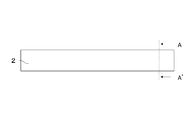
- FIG. 1A is an example of the flow path member of the present disclosure, and is a perspective view.
- FIG. 1B is an example of the flow path member of the present disclosure, and is a side view.
- FIG. 1C is an example of the flow path member of the present disclosure, and is a rear view.
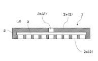
- FIG. 1D is an example of the flow path member of the present disclosure, and is a partially enlarged view of a cross section of the BB'line of FIG. 1C.
- the flow path member 1 of the present disclosure includes a base 2 and a flow path 3 located inside the base 2.
- the substrate 2 has a first surface 2a.
- the upper surface is the first surface 2a.
- the substrate 2 has a first inflow port 2b and a first outflow port 2c.
- FIG. 1A shows an example in which one first inflow port 2b is provided on the first surface 2a, which is the upper surface.
- FIG. 1C shows an example in which a plurality of first outlets 2c are provided on a surface located opposite to the first surface 2a.
- FIGS. 1A to 1D show an example in which the shape of the base 2 is a disk shape, the shape of the base 2 is not limited to this, and any shape may be used. ..
- FIG. 2 is an example of a partially enlarged view of the cross section of the line AA'of FIG. 1B.
- the flow path member 1 of the present disclosure includes a flow path 3 connected to a first inflow port 2b and a first outflow port 2c inside the substrate 2.
- the flow path 3 has a first flow path 3a along the first surface 2a.
- along the first surface 2a does not have to be exactly parallel to the first surface 2a, but may extend in the expanding direction of the first surface 2a.
- the flow path 3 has a second flow path 3b that intersects with the first flow path 3a.
- FIG. 2 shows an example in which the second flow path 3b intersects the first flow path 3a at 90 °. Note that the intersection with the first flow path 3a means that the intersection angle between the first flow path 3a and the second flow path 3b is 80 ° to 100 °.
- the substrate 2 in the flow path member 1 of the present disclosure has a first protrusion 4 in the first flow path 3a, and the surface of the first protrusion 4 is continuous with the wall surface 3c of the second flow path 3b.
- the flow path member 1 has the first protrusion 4 on the first flow path 3a in the flow path 3, and the surface of the first protrusion 4 is continuous with the wall surface 3c of the second flow path 3b.
- the first protrusion 4 is a cross section as shown in FIG. 2, in which a straight line is drawn with reference to the inner wall (lower wall in the drawing) in front of the first protrusion 4, and is 20 ⁇ m or more than the virtual line extending this straight line. It means something that stands out.
- a straight line is drawn with reference to the inner wall (lower wall in the drawing) in front of the first protrusion 4, and is 20 ⁇ m or more than the virtual line extending this straight line. It means something that stands out.
- the inner wall in front of the first protrusion 4 has roughness (unevenness), an average portion of roughness is taken and a straight line is drawn.
- the flow path member 1 of the present disclosure has been described with reference to FIGS. 1A to 1D and FIG. 2, but as the fluid path of the flow path member 1, the inflow gas enters from the first inflow port 2b. It passes through at least the first flow path 3a and the second flow path 3b in the flow path 3, and is discharged from the first outlet 2c.
- the fluid flowing through the flow path 3 of the flow path member 1 may be a liquid or a gas as long as it is suitable for the intended use.
- FIG. 3 is another example of a partially enlarged view of the cross section of the line AA'of FIG. 1B.
- the flow path members will be described with reference numerals 11.
- the flowing gas floats due to the presence of the first protrusion 4, and a flow toward the wall 6 is formed, and the flowing gas returned from the wall 6 and the flowing gas flowing through the first flow path 3a The collision with the gas facilitates the flow to the second flow path 3b. Therefore, when the above configuration is satisfied, the flow of gas in the flow becomes smooth, and the fallen object can be retained by the first protrusion 4.
- FIG. 4 is another example of a partially enlarged view of the cross section of the line AA'of FIG. 1B.
- the flow path members will be described with reference numerals 12.
- the wall 6 is provided on the end surface of the first flow path 3a, and the extension portion 3d of the first flow path 3a is further provided between the wall 6 and the second flow path 3b. You may. When such a configuration is satisfied, even if a foreign substance or the like is carried by the floating gas in the flow, it can be kept in the extension portion 3d.
- FIGS. 5 and 6 are other examples of partially enlarged views of the cross section of the line AA'of FIG. 1B.
- the flow path members will be described with reference numerals 13 and 14.
- the wall 6 of the substrate 2 in the flow path members 13 and 14 may have a recess 6a.
- the space created by the recess 6a becomes a pocket for foreign matter and the like, and the foreign matter and the like carried by the flowing gas surfaced by the first protrusion 4 can be retained.
- FIG. 7 is another example of a partially enlarged view of the cross section of the line AA'of FIG. 1B.
- the flow path member will be described by adding a reference numeral of 15.
- the substrate 2 in the flow path member 15 has a second protrusion on the extension portion 3d, and the surface of the second protrusion 5 is continuous with the wall surface 3c of the second flow path 3b. May be good.
- the flowing gas returned from the wall 6 floats, so that the flow to the second flow path 3b can be made smoother. it can.
- a pocket shape is formed between the second protrusion 5 provided on the extension portion 3d and the wall 6, and foreign matter and the like carried by the flowing gas surfaced by the first protrusion 4 can be retained.
- the height of the first protrusion 4 may be higher in the first protrusion 4 and the second protrusion 5.
- FIG. 8 is another example of a partially enlarged view of the cross section of the line AA'of FIG. 1B.
- the flow path member will be described with reference to 16.
- the first protrusion 4 in the flow path member 16 may include a first inclined surface 4a that becomes higher as it approaches the second flow path 3b. Even when such a configuration is satisfied, foreign matter and the like can be retained, and the flowing gas can be more easily floated.
- FIG. 9 is another example of a partially enlarged view of the cross section of the line AA'of FIG. 1B.
- the flow path member will be described with a reference numeral of 17.
- the second protrusion 5 in the flow path member 17 may include a second inclined surface 5a that becomes higher as it approaches the second flow path 3b. Even when such a configuration is satisfied, foreign matter and the like can be retained, and the flowing gas returned from the wall 6 can be more easily floated.
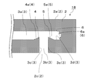
- FIG. 10 is another example of a partially enlarged view of the cross section of the line AA'of FIG. 1B.
- the flow path members will be described with reference numerals 18.
- the wall 6 of the substrate 2 in the flow path member 18 may have a recess 6a.
- the space created by the recess 6a also becomes a pocket for foreign matter and the like, and the first protrusion 4 Foreign matter and the like carried by the flowing gas that has surfaced can be further retained.
- FIG. 11 is another example of a partially enlarged view of the cross section of the line AA'of FIG. 1B.
- the flow path members will be described with reference numerals 19.
- at least one of the first protrusion 4 or the second protrusion 5 in the flow path member 19 has a top portion 7 that is smoothly connected, and the top portion 7 is the wall surface 3c of the second flow path 3b. It may be located outside.
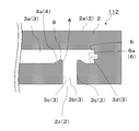
- FIG. 12 is another example of a partially enlarged view of the cross section of the line AA'of FIG. 1B.
- the flow path member will be described with the reference numeral 111.
- at least one of the first inclined surface 4a and the second inclined surface 5a of the flow path member 111 has a concave portion 8 having a concave shape in the cross section at the center in the width direction of the flow path 3.
- the concave portion 8 may be provided over the entire surface.
- FIG. 13 is another example of a partially enlarged view of the cross section of the line AA'of FIG. 1B.
- the flow path member will be described with the reference numeral 112.
- the top portion 7 of the flow path member 112 may be provided with a plane 9 along the first surface 2a.
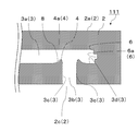
- FIG. 14 is another example of a partially enlarged view of the cross section of the line AA'of FIG. 1B.
- the flow path member will be described with the reference numeral 113.
- the inclination of the second inclined surface 5a in the flow path member 113 may be larger than the inclination of the first inclined surface 4a.
- FIG. 15 is another example of the flow path member of the present disclosure.
- a perspective view of an intersection of the first flow path 3a and the second flow path 3b will be described.
- a protrusion 10 including a first protrusion 4 and a second protrusion 5 may be provided so as to orbit the intersection of the first flow path 3a and the second flow path 3b.
- the substrate 2 in the flow path member 1 of the present disclosure may be made of any material such as resin, metal and ceramics.
- the substrate 2 is made of ceramics, it is superior to resin or metal in terms of mechanical strength, heat resistance, corrosion resistance, and the like.
- the ceramics are aluminum oxide ceramics, zirconium oxide ceramics, silicon nitride ceramics, aluminum nitride ceramics, silicon carbide ceramics, cordierite ceramics, mulite ceramics, and the like.
- aluminum oxide ceramics contain 70% by mass or more of aluminum oxide out of 100% by mass of all the components constituting the ceramics. The same applies to other ceramics.
- the material of the target substrate can be confirmed by the following method.
- the target substrate is measured using an X-ray diffractometer (XRD), and the obtained 2 ⁇ (2 ⁇ is a diffraction angle) value is collated with the JCPDS card.
- XRD X-ray diffractometer
- 2 ⁇ 2 ⁇ is a diffraction angle
- a case where the presence of aluminum oxide is confirmed on the target substrate by XRD will be described as an example.
- a quantitative analysis of aluminum (Al) is performed using an ICP emission spectroscopic analyzer (ICP) or a fluorescent X-ray analyzer (XRF). Then, if the content converted from the Al content measured by ICP or XRF into aluminum oxide (Al 2 O 3 ) is 70% by mass or more, the target substrate is made of aluminum oxide ceramics.
- ICP ICP emission spectroscopic analyzer
- XRF fluorescent X-ray analyzer
- the flow path member 1 of the present disclosure When the flow path member 1 of the present disclosure is provided with a plurality of first outlets 2c and the substrate 2 is made of ceramics, it can be suitably used for a shower plate used in a semiconductor manufacturing apparatus that requires corrosion resistance. Further, since the flow path member 1 of the present disclosure has little deterioration in the quality of the inflow gas, the quality of the object to be processed is high.
- the flow path member 1 of the present disclosure when the first protrusion 4 projects toward the first surface 2a, the flow gas flowing in the first flow path 3a is floated by the first protrusion 4 due to the floating of the flowing gas. Heat can be efficiently exchanged on the first surface 2a.
- the first surface 2a is a heat exchange surface, and the flow path member 1 satisfying such a configuration is a heat exchanger.
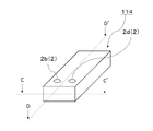
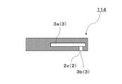
- FIG. 16A is another example of the flow path member of the present disclosure, and is a perspective view.
- FIG. 16B is another example of the flow path member of the present disclosure, and is a partially enlarged view of a cross section of the CC'line of FIG. 16A.
- FIG. 16C is another example of the flow path member of the present disclosure, and is a partially enlarged view of a cross section of the DD'line of FIG. 16A.
- the flow path member 114 of the present disclosure includes a second inflow port 2d in addition to the first inflow port 2b connected to the flow path 3 shown in the flow path member 1 of the present disclosure. At this time, if the region including the first protrusion 4 is a reaction region, the reaction efficiency is improved by promoting the stirring of the two types of fluids, which is suitable as a chemical reactor.
- raw material powders such as aluminum oxide (Al 2 O 3 ) powder, silicon nitride (Si 3 N 4 ) powder, aluminum nitride (AlN) powder, silicon carbide (SiC) powder, sintering aids, binders, solvents and A slurry is prepared by adding a predetermined amount of a dispersant or the like and mixing them.
- a green sheet is formed by the doctor blade method using this slurry.
- the slurry is spray-dried by a spray granulation method (spray drying method) to granulate, and a green sheet is formed by a roll compaction method.
- the obtained green sheet is processed by using a known method such as a laser and a mold so as to have a desired shape.
- a groove or a hole having an arbitrary shape to be a first flow path and a second flow path is formed on the green sheet.
- a green sheet corresponding to the first protrusion and the second protrusion is prepared.
- the green sheets are laminated by the laminating method to obtain a molded product.
- the green sheet corresponding to the first protrusion may be arranged so that the direction in which the flowing gas flows is confirmed and the surface of the first protrusion is continuous with the wall surface of the second flow path.
- the green sheet corresponding to the second protrusion may be arranged so that the surface of the second protrusion is continuous with the wall surface of the second flow path.
- the green sheet corresponding to the first protrusion and the second protrusion is arranged so as to orbit the intersection of the first flow path and the second flow path. You may.
- first protrusion when the first protrusion is provided with a first inclined surface that becomes higher as it approaches the second flow path, a green sheet having an inclination corresponding to the first protrusion is prepared, and the green sheet is arranged. In this case, it may be arranged so that it becomes higher as it approaches the second flow path.
- second protrusion when the second protrusion is provided with a second inclined surface that becomes higher as it approaches the second flow path, a green sheet having an inclination corresponding to the second protrusion is prepared, and the green sheet is arranged. In this case, it may be arranged so that it becomes higher as it approaches the second flow path.
- the second flow path is formed in the green sheet constituting the first flow path.
- the length of the groove or hole may be adjusted so that the wall is continuous with the wall surface of the wall.
- the green sheet constituting the first flow path is used.
- the length of the groove or hole may be adjusted so that the extension of the first flow path is provided between the wall and the second flow path.
- the wall may be composed of a plurality of green sheets, and the lengths of the grooves or holes may be adjusted respectively.
- the first protrusion when provided with a smoothly connected top located outside the wall surface of the second flow path, it is outside the wall surface of the second flow path as a green sheet corresponding to the first protrusion.
- a material having a smoothly connected top located in is prepared, and when arranging the green sheet, the smoothly connected top may be arranged so as to be located outside the outer diameter of the second flow path.
- the second protrusion when the second protrusion is provided with a smoothly connected top located outside the wall surface of the second flow path, it is outside the wall surface of the second flow path as a green sheet corresponding to the second protrusion.
- a material having a smoothly connected top located in is prepared, and when arranging the green sheet, the smoothly connected top may be arranged so as to be located outside the outer diameter of the second flow path.
- first protrusion and the second protrusion are provided with a smoothly connected top located outside the wall surface of the second flow path
- the first protrusion and the second protrusion are used as a green sheet corresponding to the first protrusion and the second protrusion.
- the first protrusion when the first protrusion is provided on the first inclined surface with a concave portion having a concave shape in a cross section at the center in the width direction of the flow path over the entire surface, the first protrusion is a green sheet corresponding to the first protrusion.
- the concave portion having a concave shape may be arranged so as to be located over the entire surface.
- the second protrusion when the second protrusion is provided on the second inclined surface with a concave portion having a concave shape in a cross section at the center in the width direction of the flow path over the entire surface, the second protrusion is used as a green sheet corresponding to the second protrusion.
- the concave portion having a concave shape may be arranged so as to be located over the entire surface.
- the first protrusion and the second protrusion are provided on the first inclined surface and the second inclined surface with a concave portion having a concave shape in the cross section at the center in the width direction of the flow path
- the first As a green sheet corresponding to the first protrusion and the second protrusion, a green sheet having a concave portion having a concave shape with a cross section at the center in the width direction of the flow path on the first inclined surface and the second inclined surface is prepared.
- the concave portion having a concave shape may be arranged on the first inclined surface and the second inclined surface so as to be located over the entire surface in the cross section at the center in the width direction of the flow path.
- the top portion smoothly connected to the first protrusion is provided with a flat surface along the first surface
- the top portion smoothly connected as a green sheet corresponding to the first protrusion is along the first surface.
- a flat surface may be prepared, and when arranging the green sheet, the smoothly connected tops may be arranged so as to be a flat surface along the first surface.
- the top portion smoothly connected to the second protrusion is provided with a flat surface along the first surface
- the top portion smoothly connected as a green sheet corresponding to the second protrusion is along the first surface.
- a flat surface may be prepared, and when arranging the green sheet, the smoothly connected tops may be arranged so as to be a flat surface along the first surface.
- the top portion that smoothly connects the first protrusion and the second protrusion is provided with a plane along the first surface
- the first protrusion and the second protrusion are smoothly connected as a green sheet corresponding to the first protrusion and the second protrusion.
- a top having a flat surface along the first surface may be prepared, and the smoothly connected tops may be arranged so as to be a plane along the first surface when arranging the green sheet.
- the second inclination of the second protrusion is used as a green sheet corresponding to the second protrusion and the first protrusion.
- the above-mentioned slurry may be used as the bonding agent used when laminating the green sheets.
- the obtained molded product is dried and degreased, and then fired according to the firing conditions of each raw material powder to obtain the flow path member of the present disclosure.
- the direction is toward a desired position as the intersection of the first flow path and the second flow path.
- the drill may be advanced in the direction of the first flow path from the second flow path to form the portion to be the first protrusion together with the formation of the portion to be the second flow path. Further, in the green sheet before laminating, the drill may be advanced toward a desired position at the intersection of the first flow path and the second flow path.
- Flow path member 2 Base 2a: First surface 2b: First inflow port 2c: First outflow port 2d: Second inflow port 3: Flow path 3a: First flow path 3b: Second flow path 3c: Wall surface 3d: Extension 4: 1st protrusion 4a: 1st inclined surface 5; 2nd protrusion 5a: 2nd inclined surface 6: Wall 6a: Recessed 7: Top 8: Concave 9: Flat surface 10: Protruding part
Abstract
A flow path member according to the present disclosure is provided with: a base having a first surface and further having a first inflow port and a first outflow port; and a flow path which connects to the first inflow port and the first outflow port inside the base. The flow path has a first flow path along the first surface and a second flow path which intersects the first flow path. The base has a first protrusion in the first flow path, and a surface of the first protrusion is continuous with a wall surface of the second flow path.
Description
本開示は、流路部材に関する。
This disclosure relates to a flow path member.
流路部材は、様々な用途に広く用いられている。例えば、半導体の製造工程では、基板上にガスを供給し、化学的気相蒸着(CVD)法により酸化シリコンまたは窒化シリコン等の薄膜を基板上に形成する成膜工程が行なわれる。
The flow path member is widely used for various purposes. For example, in the semiconductor manufacturing process, a film forming step is performed in which a gas is supplied onto the substrate and a thin film such as silicon oxide or silicon nitride is formed on the substrate by a chemical vapor deposition (CVD) method.
ここで、成膜工程では、ガスの供給にあたり、内部に流路を備え、この流路に繋がる複数の吐出孔からガスを供給することができる流路部材(シャワープレート)が用いられる(例えば、特許文献1を参照)。
Here, in the film forming step, a flow path member (shower plate) having a flow path inside and capable of supplying gas from a plurality of discharge holes connected to the flow path is used for supplying the gas (for example, a shower plate). See Patent Document 1).
また、特許文献2には、セラミックスからなるマニホールド形式の流路部材(シャワープレート)が記載されている。
Further, Patent Document 2 describes a manifold type flow path member (shower plate) made of ceramics.
また、特許文献3には、セラミックスシートを積層することによって流路部材(シャワープレート)を作成することが記載されている。
Further, Patent Document 3 describes that a flow path member (shower plate) is created by laminating ceramic sheets.
本開示の流路部材は、第1面を有し、さらに第1流入口および第1流出口を有する基体と、該基体の内部において前記第1流入口および前記第1流出口に繋がる流路とを備える。該流路は、前記第1面に沿う第1流路と、該第1流路と交わる第2流路とを有する。前記第1流路は、第1突起を有する。前記第1突起の表面は、前記第2流路の壁面と連続している。
The flow path member of the present disclosure includes a substrate having a first surface and further having a first inlet and a first outlet, and a flow path connected to the first inlet and the first outlet inside the substrate. And. The flow path has a first flow path along the first surface and a second flow path intersecting the first flow path. The first flow path has a first protrusion. The surface of the first protrusion is continuous with the wall surface of the second flow path.
本開示の流路部材は、流入ガスの品質低下が少ない。
The flow path member of the present disclosure has little deterioration in the quality of the inflow gas.
本開示の流路部材は、流入ガスの流れが阻害されにくい。
The flow path member of the present disclosure is less likely to obstruct the flow of inflow gas.
本開示のシャワープレートは、被処理物の品質が高い。
The shower plate of the present disclosure has high quality of the object to be treated.
本開示の熱交換器は、熱交換効率に優れる。
The heat exchanger of the present disclosure is excellent in heat exchange efficiency.
本開示の化学反応器は、流体の反応効率に優れる。
The chemical reactor of the present disclosure is excellent in fluid reaction efficiency.
本開示の流路部材について、図面を参照しながら、以下に詳細に説明する。
The flow path member of the present disclosure will be described in detail below with reference to the drawings.
図1Aは、本開示の流路部材の一例であり、斜視図である。
FIG. 1A is an example of the flow path member of the present disclosure, and is a perspective view.
図1Bは、本開示の流路部材の一例であり、側面図である。
FIG. 1B is an example of the flow path member of the present disclosure, and is a side view.
図1Cは、本開示の流路部材の一例であり、背面図である。
FIG. 1C is an example of the flow path member of the present disclosure, and is a rear view.
図1Dは、本開示の流路部材の一例であり、図1CのB-B’線の断面の部分拡大図である。
FIG. 1D is an example of the flow path member of the present disclosure, and is a partially enlarged view of a cross section of the BB'line of FIG. 1C.
本開示の流路部材1は、基体2と、基体2の内部に位置する流路3とを備える。基体2は、第1面2aを有する。図1Aの斜視図においては、上面が第1面2aである。また、基体2は、第1流入口2bおよび第1流出口2cを有する。なお、図1Aにおいては、上面である第1面2aに第1流入口2bを1つ備えている例を示している。また、図1Cにおいては、第1面2aの反対に位置する面に、複数の第1流出口2cを備えている例を示している。なお、図1Aから図1Dでは、基体2の形状が円板状である例を示しているが、基体2の形状はこれに限定されるものではなく、どのような形状であっても構わない。
The flow path member 1 of the present disclosure includes a base 2 and a flow path 3 located inside the base 2. The substrate 2 has a first surface 2a. In the perspective view of FIG. 1A, the upper surface is the first surface 2a. Further, the substrate 2 has a first inflow port 2b and a first outflow port 2c. Note that FIG. 1A shows an example in which one first inflow port 2b is provided on the first surface 2a, which is the upper surface. Further, FIG. 1C shows an example in which a plurality of first outlets 2c are provided on a surface located opposite to the first surface 2a. Although FIGS. 1A to 1D show an example in which the shape of the base 2 is a disk shape, the shape of the base 2 is not limited to this, and any shape may be used. ..
次に、図2は、図1BのA-A’線の断面の部分拡大図の一例である。なお、以下においては、図2において示されておらず、図1Aから図1Dにのみに示された符号も付して説明する。本開示の流路部材1は、基体2の内部において第1流入口2bおよび第1流出口2cに繋がる流路3を備える。この流路3は、第1面2aに沿う第1流路3aを有する。ここで、第1面2aに沿うとは、第1面2aに厳密に平行である必要は無く、第1面2aの拡がる方向に延びるものであればよい。
Next, FIG. 2 is an example of a partially enlarged view of the cross section of the line AA'of FIG. 1B. In the following, reference numerals which are not shown in FIG. 2 and are shown only in FIGS. 1A to 1D will be described. The flow path member 1 of the present disclosure includes a flow path 3 connected to a first inflow port 2b and a first outflow port 2c inside the substrate 2. The flow path 3 has a first flow path 3a along the first surface 2a. Here, along the first surface 2a does not have to be exactly parallel to the first surface 2a, but may extend in the expanding direction of the first surface 2a.
また、流路3は、第1流路3aと交わる第2流路3bを有する。図2において、第2流路3bが、第1流路3aと90°で交わっている例を示している。なお、第1流路3aと交わるとは、第1流路3aと第2流路3bとの交差角度が80°~100°のことをいう。
Further, the flow path 3 has a second flow path 3b that intersects with the first flow path 3a. FIG. 2 shows an example in which the second flow path 3b intersects the first flow path 3a at 90 °. Note that the intersection with the first flow path 3a means that the intersection angle between the first flow path 3a and the second flow path 3b is 80 ° to 100 °.
そして、本開示の流路部材1における基体2は、第1流路3aに第1突起4を有しており、第1突起4の表面が、第2流路3bの壁面3cと連続している。このように、流路部材1が、流路3における第1流路3aに第1突起4を有しており、第1突起4の表面が、第2流路3bの壁面3cと連続していることにより、流路3中を流れる流中ガスに例えば、流路部材1の設置時や配管時に誤って異物等が混入していたとしても、第1突起4によって留めることができる。それ故、本開示の流路部材1を用いれば、流中ガスに異物等が含まれることが少ないため、流入ガスの品質低下が少ない。
The substrate 2 in the flow path member 1 of the present disclosure has a first protrusion 4 in the first flow path 3a, and the surface of the first protrusion 4 is continuous with the wall surface 3c of the second flow path 3b. There is. As described above, the flow path member 1 has the first protrusion 4 on the first flow path 3a in the flow path 3, and the surface of the first protrusion 4 is continuous with the wall surface 3c of the second flow path 3b. As a result, even if foreign matter or the like is erroneously mixed in the flowing gas flowing through the flow path 3 at the time of installation of the flow path member 1 or at the time of piping, it can be stopped by the first protrusion 4. Therefore, when the flow path member 1 of the present disclosure is used, foreign matter and the like are less likely to be contained in the flowing gas, so that the quality of the inflow gas is less deteriorated.
なお、第1突起4とは、図2に示すような断面において、第1突起4の手前の内壁(図示における下壁)を基準に直線を引き、この直線を延ばした仮想線よりも20μm以上突出しているもののことをいう。第1突起4の手前の内壁が、粗さ(凹凸)を有するものであるときには、粗さの平均的な部分を取り、直線を引くものとする。
The first protrusion 4 is a cross section as shown in FIG. 2, in which a straight line is drawn with reference to the inner wall (lower wall in the drawing) in front of the first protrusion 4, and is 20 μm or more than the virtual line extending this straight line. It means something that stands out. When the inner wall in front of the first protrusion 4 has roughness (unevenness), an average portion of roughness is taken and a straight line is drawn.
ここまで、図1Aから図1Dおよび図2を用いて本開示の流路部材1について説明してきたが、この流路部材1の流体の経路としては、流入ガスが第1流入口2bから入り、流路3における第1流路3aおよび第2流路3bを少なくとも通り、第1流出口2cから排出される。なお、流路部材1の流路3を流れる流体は、使用用途に適したものであればよく、液体であっても気体であってもよい。
Up to this point, the flow path member 1 of the present disclosure has been described with reference to FIGS. 1A to 1D and FIG. 2, but as the fluid path of the flow path member 1, the inflow gas enters from the first inflow port 2b. It passes through at least the first flow path 3a and the second flow path 3b in the flow path 3, and is discharged from the first outlet 2c. The fluid flowing through the flow path 3 of the flow path member 1 may be a liquid or a gas as long as it is suitable for the intended use.
次に、図3は、図1BのA-A’線の断面の部分拡大図の他の例である。この例においては、流路部材に11の符号を付して説明する。この例に示すように、流路部材11における基体2が、第1流路3aの端面に壁6を有しており、壁6が、第2流路3bの壁面3cと連続していてもよい。このような構成を満たすときには、流中ガスが第1突起4の存在により浮上し、壁6に向かう流れができ、壁6から折り返してきた流中ガスと、第1流路3aを流れる流中ガスとのぶつかりにより、第2流路3bへ流れやすくなる。そのため、上記構成を満たしているときには、流中ガスの流れがスムーズになるとともに、第1突起4により脱落物を留まらせることができる。
Next, FIG. 3 is another example of a partially enlarged view of the cross section of the line AA'of FIG. 1B. In this example, the flow path members will be described with reference numerals 11. As shown in this example, even if the substrate 2 in the flow path member 11 has a wall 6 on the end surface of the first flow path 3a and the wall 6 is continuous with the wall surface 3c of the second flow path 3b. Good. When such a configuration is satisfied, the flowing gas floats due to the presence of the first protrusion 4, and a flow toward the wall 6 is formed, and the flowing gas returned from the wall 6 and the flowing gas flowing through the first flow path 3a The collision with the gas facilitates the flow to the second flow path 3b. Therefore, when the above configuration is satisfied, the flow of gas in the flow becomes smooth, and the fallen object can be retained by the first protrusion 4.
次に、図4は、図1BのA-A’線の断面の部分拡大図の他の例である。この例においては、流路部材に12の符号を付して説明する。この例に示すように、第1流路3aの端面に壁6を有しており、さらに壁6と第2流路3bとの間に、第1流路3aの延長部3dを有していてもよい。このような構成を満たしているときには、浮上した流中ガスによって異物等が運ばれたとしても、延長部3dに留まらせることができる。
Next, FIG. 4 is another example of a partially enlarged view of the cross section of the line AA'of FIG. 1B. In this example, the flow path members will be described with reference numerals 12. As shown in this example, the wall 6 is provided on the end surface of the first flow path 3a, and the extension portion 3d of the first flow path 3a is further provided between the wall 6 and the second flow path 3b. You may. When such a configuration is satisfied, even if a foreign substance or the like is carried by the floating gas in the flow, it can be kept in the extension portion 3d.
次に、図5、図6は、図1BのA-A’線の断面の部分拡大図の他の例である。この例においては、流路部材に13、14の符号を付して説明する。この例に示すように、流路部材13、14における基体2の壁6が、凹部6aを有していてもよい。このような構成を満たしているときには、凹部6aによって生じたスペースが異物等のポケットとなり、第1突起4によって浮上した流中ガスによって運ばれた異物等を留まらせることができる。
Next, FIGS. 5 and 6 are other examples of partially enlarged views of the cross section of the line AA'of FIG. 1B. In this example, the flow path members will be described with reference numerals 13 and 14. As shown in this example, the wall 6 of the substrate 2 in the flow path members 13 and 14 may have a recess 6a. When such a configuration is satisfied, the space created by the recess 6a becomes a pocket for foreign matter and the like, and the foreign matter and the like carried by the flowing gas surfaced by the first protrusion 4 can be retained.
次に、図7は、図1BのA-A’線の断面の部分拡大図の他の例である。この例においては、流路部材に15の符号を付して説明する。この例に示すように、流路部材15における基体2が、延長部3dに第2突起を有しており、第2突起5の表面が、第2流路3bの壁面3cと連続していてもよい。このような構成を満たしているときには、図4で説明した効果に加えて、壁6から折り返してきた流中ガスが浮上することにより、第2流路3bへの流れをよりスムーズにすることができる。また、延長部3dに設けられた第2突起5と壁6との間でポケット形状となり、第1突起4によって浮上した流中ガスによって運ばれた異物等を留まらせることができる。
Next, FIG. 7 is another example of a partially enlarged view of the cross section of the line AA'of FIG. 1B. In this example, the flow path member will be described by adding a reference numeral of 15. As shown in this example, the substrate 2 in the flow path member 15 has a second protrusion on the extension portion 3d, and the surface of the second protrusion 5 is continuous with the wall surface 3c of the second flow path 3b. May be good. When such a configuration is satisfied, in addition to the effect described with reference to FIG. 4, the flowing gas returned from the wall 6 floats, so that the flow to the second flow path 3b can be made smoother. it can. Further, a pocket shape is formed between the second protrusion 5 provided on the extension portion 3d and the wall 6, and foreign matter and the like carried by the flowing gas surfaced by the first protrusion 4 can be retained.
また、第1突起4と第2突起5とにおいて、第1突起4の高さが高くてもよい。このような構成を満たすときには、壁6から折り返してきた流中ガスの流れが強くなりすぎることなく、流中ガスを第2流路3bへと導くことができる。
Further, the height of the first protrusion 4 may be higher in the first protrusion 4 and the second protrusion 5. When such a configuration is satisfied, the flowing gas can be guided to the second flow path 3b without the flow of the flowing gas returning from the wall 6 becoming too strong.
次に、図8は、図1BのA-A’線の断面の部分拡大図の他の例である。この例においては、流路部材に16の符号を付して説明する。この例に示すように、流路部材16における第1突起4が、第2流路3bに近づくにつれて高くなっている第1傾斜面4aを備えていてもよい。このような構成を満たすときにも、異物等を留まらせることができると共に、流中ガスをより浮上させやすい。
Next, FIG. 8 is another example of a partially enlarged view of the cross section of the line AA'of FIG. 1B. In this example, the flow path member will be described with reference to 16. As shown in this example, the first protrusion 4 in the flow path member 16 may include a first inclined surface 4a that becomes higher as it approaches the second flow path 3b. Even when such a configuration is satisfied, foreign matter and the like can be retained, and the flowing gas can be more easily floated.
次に、図9は、図1BのA-A’線の断面の部分拡大図の他の例である。この例においては、流路部材に17の符号を付して説明する。この例に示すように、流路部材17における第2突起5が、第2流路3bに近づくにつれて高くなっている第2傾斜面5aを備えていてもよい。このような構成を満たすときにも、異物等を留まらせることができると共に、壁6から折り返してきた流中ガスをより浮上させやすい。
Next, FIG. 9 is another example of a partially enlarged view of the cross section of the line AA'of FIG. 1B. In this example, the flow path member will be described with a reference numeral of 17. As shown in this example, the second protrusion 5 in the flow path member 17 may include a second inclined surface 5a that becomes higher as it approaches the second flow path 3b. Even when such a configuration is satisfied, foreign matter and the like can be retained, and the flowing gas returned from the wall 6 can be more easily floated.
次に、図10は、図1BのA-A’線の断面の部分拡大図の他の例である。この例においては、流路部材に18の符号を付して説明する。この例に示すように、流路部材18における基体2の壁6が、凹部6aを有していてもよい。このような構成を満たしているときには、延長部3dに設けられた第2突起5と壁6との間のポケット形状に加え、凹部6aによって生じたスペースも異物等のポケットとなり、第1突起4によって浮上した流中ガスによって運ばれた異物等をさらに留まらせることができる。
Next, FIG. 10 is another example of a partially enlarged view of the cross section of the line AA'of FIG. 1B. In this example, the flow path members will be described with reference numerals 18. As shown in this example, the wall 6 of the substrate 2 in the flow path member 18 may have a recess 6a. When such a configuration is satisfied, in addition to the pocket shape between the second protrusion 5 and the wall 6 provided in the extension portion 3d, the space created by the recess 6a also becomes a pocket for foreign matter and the like, and the first protrusion 4 Foreign matter and the like carried by the flowing gas that has surfaced can be further retained.
次に、図11は、図1BのA-A’線の断面の部分拡大図の他の例である。この例においては、流路部材に19の符号を付して説明する。この例に示すように、流路部材19における第1突起4または第2突起5の少なくとも一方が、滑らかにつながっている頂部7を有しており、頂部7が第2流路3bの壁面3cよりも外側に位置していてもよい。このような構成を満たしているときには、異物等を留まらせることができると共に、第1突起4で浮上させた流中ガスと、壁6から折り返して第2突起5で浮上させた流中ガスとが合流する第1流路3aと第2流路3bとの交差部分の流中ガスを、滑らかに且つ効率的に第2流路3bへ流すことができる。
Next, FIG. 11 is another example of a partially enlarged view of the cross section of the line AA'of FIG. 1B. In this example, the flow path members will be described with reference numerals 19. As shown in this example, at least one of the first protrusion 4 or the second protrusion 5 in the flow path member 19 has a top portion 7 that is smoothly connected, and the top portion 7 is the wall surface 3c of the second flow path 3b. It may be located outside. When such a configuration is satisfied, foreign matter and the like can be retained, and the flowing gas floated by the first protrusion 4 and the flowing gas folded back from the wall 6 and floated by the second protrusion 5 The flowing gas at the intersection of the first flow path 3a and the second flow path 3b, where the two flows together, can be smoothly and efficiently flowed to the second flow path 3b.
次に、図12は、図1BのA-A’線の断面の部分拡大図の他の例である。この例においては、流路部材に111の符号を付して説明する。この例に示すように、流路部材111における第1傾斜面4aまたは第2傾斜面5aの少なくとも一方に、流路3の幅方向中心の断面で、形状が凹となる凹状部8を有しており、凹状部8を全面に亘って備えていてもよい。このような構成を満たすときには、流中ガスをより浮上させやすくできると共に、流中ガスの流れを凹状部8によって変化させることができるため、より異物等を留まらせることができる。
Next, FIG. 12 is another example of a partially enlarged view of the cross section of the line AA'of FIG. 1B. In this example, the flow path member will be described with the reference numeral 111. As shown in this example, at least one of the first inclined surface 4a and the second inclined surface 5a of the flow path member 111 has a concave portion 8 having a concave shape in the cross section at the center in the width direction of the flow path 3. The concave portion 8 may be provided over the entire surface. When such a configuration is satisfied, the flowing gas can be more easily floated, and the flow of the flowing gas can be changed by the concave portion 8, so that foreign matter and the like can be more retained.
次に、図13は、図1BのA-A’線の断面の部分拡大図の他の例である。この例においては、流路部材に112の符号を付して説明する。この例に示すように、流路部材112における頂部7に、第1面2aに沿う平面9を備えてもよい。このような構成を満たすときには、異物等を留まらせることができると共に、浮上させた流中ガスの流量を多く確保することができるため、流中ガスを効率的に第2流路3bへ流すことができる。
Next, FIG. 13 is another example of a partially enlarged view of the cross section of the line AA'of FIG. 1B. In this example, the flow path member will be described with the reference numeral 112. As shown in this example, the top portion 7 of the flow path member 112 may be provided with a plane 9 along the first surface 2a. When such a configuration is satisfied, foreign matter and the like can be retained, and a large flow rate of the floating gas in the flow can be secured. Therefore, the gas in the flow can be efficiently flowed to the second flow path 3b. Can be done.
次に、図14は、図1BのA-A’線の断面の部分拡大図の他の例である。この例においては、流路部材に113の符号を付して説明する。この例に示すように、流路部材113における第2傾斜面5aの傾きを、第1傾斜面4aの傾きよりも大きくしてもよい。このような構成を満たすときには、異物等を留まらせることができると共に、壁6から折り返してきた流中ガスに含まれる異物等をより留まらせることができる。
Next, FIG. 14 is another example of a partially enlarged view of the cross section of the line AA'of FIG. 1B. In this example, the flow path member will be described with the reference numeral 113. As shown in this example, the inclination of the second inclined surface 5a in the flow path member 113 may be larger than the inclination of the first inclined surface 4a. When such a configuration is satisfied, foreign matter and the like can be retained, and foreign matter and the like contained in the flowing gas folded back from the wall 6 can be more retained.
また、図15は、本開示の流路部材の他の例である。この例においては、第1流路3aと第2流路3bとの交差部分の斜視図を用いて説明する。この例に示すように、第1流路3aと第2流路3bとの交差部分を周回するように第1突起4および第2突起5を含んだ突部10を備えてもよい。このような構成を満たすときには、あらゆる方向からの異物等を留まらせることができる。
Further, FIG. 15 is another example of the flow path member of the present disclosure. In this example, a perspective view of an intersection of the first flow path 3a and the second flow path 3b will be described. As shown in this example, a protrusion 10 including a first protrusion 4 and a second protrusion 5 may be provided so as to orbit the intersection of the first flow path 3a and the second flow path 3b. When satisfying such a configuration, foreign matter or the like from all directions can be retained.
以上、流路部材の構成の差異により1、11~113の符号を付して説明したが、以下においては、流路部材1と記載して説明する。
Although the above description has been given with reference numerals 1, 11 to 113 due to the difference in the configuration of the flow path member, the description will be described below as the flow path member 1.
本開示の流路部材1における基体2は、樹脂、金属およびセラミックス等、どのような材料で構成されていてもよい。基体2がセラミックスからなるときには、機械的強度、耐熱性および耐食性などの点において樹脂や金属よりも優れる。
The substrate 2 in the flow path member 1 of the present disclosure may be made of any material such as resin, metal and ceramics. When the substrate 2 is made of ceramics, it is superior to resin or metal in terms of mechanical strength, heat resistance, corrosion resistance, and the like.
ここで、セラミックスとは、酸化アルミニウム質セラミックス、酸化ジルコニウム質セラミックス、窒化珪素質セラミックス、窒化アルミニウム質セラミックス、炭化珪素質セラミックス、コージェライト質セラミックスまたはムライト質セラミックス等である。
Here, the ceramics are aluminum oxide ceramics, zirconium oxide ceramics, silicon nitride ceramics, aluminum nitride ceramics, silicon carbide ceramics, cordierite ceramics, mulite ceramics, and the like.
そして、例えば、酸化アルミニウム質セラミックスとは、セラミックスを構成する全成分100質量%のうち、酸化アルミニウムを70質量%以上含有するものである。なお、他のセラミックスについても同様である。
And, for example, aluminum oxide ceramics contain 70% by mass or more of aluminum oxide out of 100% by mass of all the components constituting the ceramics. The same applies to other ceramics.
また、対象基体の材質は、以下の方法により確認することができる。まず、X線回折装置(XRD)を用いて対象基体を測定し、得られた2θ(2θは、回折角度である。)の値より、JCPDSカードと照合する。ここでは、XRDにより対象基体に酸化アルミニウムの存在が確認された場合を例に挙げて説明する。次に、ICP発光分光分析装置(ICP)または蛍光X線分析装置(XRF)を用いて、アルミニウム(Al)の定量分析を行なう。そして、ICPまたはXRFで測定したAlの含有量から酸化アルミニウム(Al2O3)に換算した含有量が70質量%以上であれば、対象基体は酸化アルミニウム質セラミックスで構成されている。
The material of the target substrate can be confirmed by the following method. First, the target substrate is measured using an X-ray diffractometer (XRD), and the obtained 2θ (2θ is a diffraction angle) value is collated with the JCPDS card. Here, a case where the presence of aluminum oxide is confirmed on the target substrate by XRD will be described as an example. Next, a quantitative analysis of aluminum (Al) is performed using an ICP emission spectroscopic analyzer (ICP) or a fluorescent X-ray analyzer (XRF). Then, if the content converted from the Al content measured by ICP or XRF into aluminum oxide (Al 2 O 3 ) is 70% by mass or more, the target substrate is made of aluminum oxide ceramics.
そして、本開示の流路部材1が複数の第1流出口2cを備え、基体2がセラミックスからなるときには、耐食性が必要とされる半導体製造装置に用いられるシャワープレートに好適に用いることができる。そして、本開示の流路部材1が、流入ガスの品質低下が少ないものであることから、被処理物の品質が高い。
When the flow path member 1 of the present disclosure is provided with a plurality of first outlets 2c and the substrate 2 is made of ceramics, it can be suitably used for a shower plate used in a semiconductor manufacturing apparatus that requires corrosion resistance. Further, since the flow path member 1 of the present disclosure has little deterioration in the quality of the inflow gas, the quality of the object to be processed is high.
また、本開示の流路部材1は、第1突起4が第1面2aに向かって突出しているものであるときには、第1突起4による第1流路3aに流れる流中ガスの浮上により、第1面2aにおいて効率よく熱交換することができる。このとき、第1面2aは熱交換面であり、このような構成を満たす流路部材1は、熱交換器である。
Further, in the flow path member 1 of the present disclosure, when the first protrusion 4 projects toward the first surface 2a, the flow gas flowing in the first flow path 3a is floated by the first protrusion 4 due to the floating of the flowing gas. Heat can be efficiently exchanged on the first surface 2a. At this time, the first surface 2a is a heat exchange surface, and the flow path member 1 satisfying such a configuration is a heat exchanger.
図16Aは、本開示の流路部材の他の例であり、斜視図である。
FIG. 16A is another example of the flow path member of the present disclosure, and is a perspective view.
図16Bは、本開示の流路部材の他の例であり、図16AのC-C’線の断面の部分拡大図である。
FIG. 16B is another example of the flow path member of the present disclosure, and is a partially enlarged view of a cross section of the CC'line of FIG. 16A.
図16Cは、本開示の流路部材の他の例であり、図16AのD-D’線の断面の部分拡大図である。
FIG. 16C is another example of the flow path member of the present disclosure, and is a partially enlarged view of a cross section of the DD'line of FIG. 16A.
本開示の流路部材114は、本開示の流路部材1で示した流路3に繋がる第1流入口2bに加えて、さらに第2流入口2dを備えるものである。このとき、第1突起4を含む領域が反応領域であれば、2種類の流体の撹拌が促されることによって反応効率が向上するため、化学反応器として好適である。
The flow path member 114 of the present disclosure includes a second inflow port 2d in addition to the first inflow port 2b connected to the flow path 3 shown in the flow path member 1 of the present disclosure. At this time, if the region including the first protrusion 4 is a reaction region, the reaction efficiency is improved by promoting the stirring of the two types of fluids, which is suitable as a chemical reactor.
以下、本開示の流路部材の製造方法の一例について説明する。なお、流路部材がセラミックスで構成される場合を例に挙げて説明する。
Hereinafter, an example of the manufacturing method of the flow path member of the present disclosure will be described. A case where the flow path member is made of ceramics will be described as an example.
まず、酸化アルミニウム(Al2O3)粉末、窒化珪素(Si3N4)粉末、窒化アルミニウム(AlN)粉末、炭化珪素(SiC)粉末等の原料粉末に、焼結助剤、バインダ、溶媒および分散剤等を所定量添加し、混合することでスラリーを作製する。
First, raw material powders such as aluminum oxide (Al 2 O 3 ) powder, silicon nitride (Si 3 N 4 ) powder, aluminum nitride (AlN) powder, silicon carbide (SiC) powder, sintering aids, binders, solvents and A slurry is prepared by adding a predetermined amount of a dispersant or the like and mixing them.
次に、このスラリーを用いてドクターブレード法によりグリーンシートを形成する。または、スラリーを噴霧造粒法(スプレードライ法)により噴霧乾燥して造粒し、ロールコンパクション法によりグリーンシートを形成する。
Next, a green sheet is formed by the doctor blade method using this slurry. Alternatively, the slurry is spray-dried by a spray granulation method (spray drying method) to granulate, and a green sheet is formed by a roll compaction method.
そして、得られたグリーンシートに対し、所望の形状になるようにレーザおよび金型等の公知の方法を用いて加工を行なう。このとき、グリーンシートに第1流路および第2流路となる、任意形状の溝または孔を形成しておく。また、第1突起および第2突起に相当するグリーンシートを準備しておく。
Then, the obtained green sheet is processed by using a known method such as a laser and a mold so as to have a desired shape. At this time, a groove or a hole having an arbitrary shape to be a first flow path and a second flow path is formed on the green sheet. In addition, a green sheet corresponding to the first protrusion and the second protrusion is prepared.
次に、積層工法によってグリーンシート同士を積層し、成形体を得る。ここで、第1突起に相当するグリーンシートは、流中ガスの流れる方向を確認し、第1突起の表面が、第2流路の壁面と連続するように配置すればよい。第2突起に相当するグリーンシートについては、第2突起の表面が、第2流路の壁面と連続するように配置すればよい。第1突起および第2突起を有する流路部材とするときには、第1突起と第2突起の双方の表面が第2流路の壁面と連続するように配置すればよい。
Next, the green sheets are laminated by the laminating method to obtain a molded product. Here, the green sheet corresponding to the first protrusion may be arranged so that the direction in which the flowing gas flows is confirmed and the surface of the first protrusion is continuous with the wall surface of the second flow path. The green sheet corresponding to the second protrusion may be arranged so that the surface of the second protrusion is continuous with the wall surface of the second flow path. When the flow path member has the first protrusion and the second protrusion, the surfaces of both the first protrusion and the second protrusion may be arranged so as to be continuous with the wall surface of the second flow path.
また、第1突起および第2突起を有する流路部材とするときには、第1突起および第2突起に相当するグリーンシートを、第1流路と第2流路の交差部分を周回するように配置してもよい。
Further, when the flow path member has the first protrusion and the second protrusion, the green sheet corresponding to the first protrusion and the second protrusion is arranged so as to orbit the intersection of the first flow path and the second flow path. You may.
また、第1突起を、第2流路に近づくにつれて高くなっている第1傾斜面を備えるものとするときには、第1突起に相当するグリーンシートとして傾斜を有するものを準備し、グリーンシートの配置にあたって、第2流路に近づくにつれて高くなっているように配置すればよい。さらに、第2突起を、第2流路に近づくにつれて高くなっている第2傾斜面を備えるものとするときには、第2突起に相当するグリーンシートとして傾斜を有するものを準備し、グリーンシートの配置にあたって、第2流路に近づくにつれて高くなっているように配置すればよい。
Further, when the first protrusion is provided with a first inclined surface that becomes higher as it approaches the second flow path, a green sheet having an inclination corresponding to the first protrusion is prepared, and the green sheet is arranged. In this case, it may be arranged so that it becomes higher as it approaches the second flow path. Further, when the second protrusion is provided with a second inclined surface that becomes higher as it approaches the second flow path, a green sheet having an inclination corresponding to the second protrusion is prepared, and the green sheet is arranged. In this case, it may be arranged so that it becomes higher as it approaches the second flow path.
また、基体が第1流路の端面に壁を有し、壁が第2流路の壁面と連続しているものとするには、第1流路を構成するグリーンシートにおいて、第2流路の壁面と連続する壁となるように、溝または孔の長さを調整すればよい。さらに、第1流路の端面に壁を有し、壁と第2流路との間に、第1流路の延長部を有するものとするには、第1流路を構成するグリーンシートにおいて、壁と第2流路との間に、第1流路の延長部を有するように、溝または孔の長さを調整すればよい。さらに、壁が凹部を有するものとするときには、壁を複数枚のグリーンシートで構成するものとし、溝または孔の長さをそれぞれ調整すればよい。
Further, in order to make the substrate have a wall on the end surface of the first flow path and the wall is continuous with the wall surface of the second flow path, the second flow path is formed in the green sheet constituting the first flow path. The length of the groove or hole may be adjusted so that the wall is continuous with the wall surface of the wall. Further, in order to have a wall on the end face of the first flow path and an extension portion of the first flow path between the wall and the second flow path, the green sheet constituting the first flow path is used. , The length of the groove or hole may be adjusted so that the extension of the first flow path is provided between the wall and the second flow path. Further, when the wall has a recess, the wall may be composed of a plurality of green sheets, and the lengths of the grooves or holes may be adjusted respectively.
また、第1突起を、第2流路の壁面よりも外側に位置する滑らかにつながっている頂部を備えるものとするときには、第1突起に相当するグリーンシートとして第2流路の壁面よりも外側に位置する滑らかにつながっている頂部を有するものを準備し、グリーンシートの配置にあたって、滑らかにつながっている頂部を第2流路の外径よりも外側に位置するように配置すればよい。
Further, when the first protrusion is provided with a smoothly connected top located outside the wall surface of the second flow path, it is outside the wall surface of the second flow path as a green sheet corresponding to the first protrusion. A material having a smoothly connected top located in is prepared, and when arranging the green sheet, the smoothly connected top may be arranged so as to be located outside the outer diameter of the second flow path.
また、第2突起を、第2流路の壁面よりも外側に位置する滑らかにつながっている頂部を備えるものとするときには、第2突起に相当するグリーンシートとして第2流路の壁面よりも外側に位置する滑らかにつながっている頂部を有するものを準備し、グリーンシートの配置にあたって、滑らかにつながっている頂部を第2流路の外径よりも外側に位置するように配置すればよい。
Further, when the second protrusion is provided with a smoothly connected top located outside the wall surface of the second flow path, it is outside the wall surface of the second flow path as a green sheet corresponding to the second protrusion. A material having a smoothly connected top located in is prepared, and when arranging the green sheet, the smoothly connected top may be arranged so as to be located outside the outer diameter of the second flow path.
また、第1突起および第2突起を、第2流路の壁面よりも外側に位置する滑らかにつながっている頂部を備えるものとするときには、第1突起および第2突起に相当するグリーンシートとして第2流路の壁面よりも外側に位置する滑らかにつながっている頂部を有するものを準備し、グリーンシートの配置にあたって、滑らかにつながっている頂部を第2流路の外径よりも外側に位置するように配置すればよい。
Further, when the first protrusion and the second protrusion are provided with a smoothly connected top located outside the wall surface of the second flow path, the first protrusion and the second protrusion are used as a green sheet corresponding to the first protrusion and the second protrusion. Prepare a product having a smoothly connected top located outside the wall surface of the two flow paths, and in arranging the green sheet, the smoothly connected top is located outside the outer diameter of the second flow path. It may be arranged as follows.
また、第1突起を、第1傾斜面に流路の幅方向中心の断面で、形状が凹となる凹状部を全面に亘って備えるものとするときには、第1突起に相当するグリーンシートとして第1傾斜面に流路の幅方向中心の断面で、形状が凹となる凹状部を全面に亘って有するものを準備し、グリーンシートの配置にあたって、第1傾斜面に流路の幅方向中心の断面で、形状が凹となる凹状部を全面に亘って位置するように配置すればよい。
Further, when the first protrusion is provided on the first inclined surface with a concave portion having a concave shape in a cross section at the center in the width direction of the flow path over the entire surface, the first protrusion is a green sheet corresponding to the first protrusion. Prepare a cross section having a concave portion having a concave shape over the entire surface, which is a cross section at the center of the width direction of the flow path on one inclined surface. In the cross section, the concave portion having a concave shape may be arranged so as to be located over the entire surface.
また、第2突起を、第2傾斜面に流路の幅方向中心の断面で、形状が凹となる凹状部を全面に亘って備えるものとするときには、第2突起に相当するグリーンシートとして第2傾斜面に流路の幅方向中心の断面で、形状が凹となる凹状部を全面に亘って有するものを準備し、グリーンシートの配置にあたって、第2傾斜面に流路の幅方向中心の断面で、形状が凹となる凹状部を全面に亘って位置するように配置すればよい。
Further, when the second protrusion is provided on the second inclined surface with a concave portion having a concave shape in a cross section at the center in the width direction of the flow path over the entire surface, the second protrusion is used as a green sheet corresponding to the second protrusion. 2 Prepare a cross section of the center of the flow path in the width direction on the inclined surface, which has a concave portion having a concave shape over the entire surface, and when arranging the green sheet, the second inclined surface is centered on the width direction of the flow path. In the cross section, the concave portion having a concave shape may be arranged so as to be located over the entire surface.
また、第1突起および第2突起を、第1傾斜面および第2傾斜面に流路の幅方向中心の断面で、形状が凹となる凹状部を全面に亘って備えるものとするときには、第1突起および第2突起に相当するグリーンシートとして第1傾斜面および第2傾斜面に流路の幅方向中心の断面で、形状が凹となる凹状部を全面に亘って有するものを準備し、グリーンシートの配置にあたって、第1傾斜面および第2傾斜面に流路の幅方向中心の断面で、形状が凹となる凹状部を全面に亘って位置するように配置すればよい。
Further, when the first protrusion and the second protrusion are provided on the first inclined surface and the second inclined surface with a concave portion having a concave shape in the cross section at the center in the width direction of the flow path, the first As a green sheet corresponding to the first protrusion and the second protrusion, a green sheet having a concave portion having a concave shape with a cross section at the center in the width direction of the flow path on the first inclined surface and the second inclined surface is prepared. In arranging the green sheet, the concave portion having a concave shape may be arranged on the first inclined surface and the second inclined surface so as to be located over the entire surface in the cross section at the center in the width direction of the flow path.
また、第1突起を、滑らかにつながっている頂部を、第1面に沿う平面を備えるものとするときには、第1突起に相当するグリーンシートとして滑らかにつながっている頂部を、第1面に沿う平面を有するものを準備し、グリーンシートの配置にあたって、滑らかにつながっている頂部を、第1面に沿う平面となるように配置すればよい。
Further, when the top portion smoothly connected to the first protrusion is provided with a flat surface along the first surface, the top portion smoothly connected as a green sheet corresponding to the first protrusion is along the first surface. A flat surface may be prepared, and when arranging the green sheet, the smoothly connected tops may be arranged so as to be a flat surface along the first surface.
また、第2突起を、滑らかにつながっている頂部を、第1面に沿う平面を備えるものとするときには、第2突起に相当するグリーンシートとして滑らかにつながっている頂部を、第1面に沿う平面を有するものを準備し、グリーンシートの配置にあたって、滑らかにつながっている頂部を、第1面に沿う平面となるように配置すればよい。
Further, when the top portion smoothly connected to the second protrusion is provided with a flat surface along the first surface, the top portion smoothly connected as a green sheet corresponding to the second protrusion is along the first surface. A flat surface may be prepared, and when arranging the green sheet, the smoothly connected tops may be arranged so as to be a flat surface along the first surface.
また、第1突起および第2突起を、滑らかにつながっている頂部を、第1面に沿う平面を備えるものとするときには、第1突起および第2突起に相当するグリーンシートとして滑らかにつながっている頂部を、第1面に沿う平面を有するものを準備し、グリーンシートの配置にあたって、滑らかにつながっている頂部を、第1面に沿う平面となるように配置すればよい。
Further, when the top portion that smoothly connects the first protrusion and the second protrusion is provided with a plane along the first surface, the first protrusion and the second protrusion are smoothly connected as a green sheet corresponding to the first protrusion and the second protrusion. A top having a flat surface along the first surface may be prepared, and the smoothly connected tops may be arranged so as to be a plane along the first surface when arranging the green sheet.
また、第2突起の第2傾斜面の傾きを、第1突起の第1傾斜面の傾きよりも大きくするときには、第2突起および第1突起に相当するグリーンシートとして第2突起の第2傾斜面の傾きを、第1突起の第1傾斜面の傾きよりも大きくなるものを準備し、グリーンシートの配置にあたっては、第2突起の第2傾斜面の傾きを、第1突起の第1傾斜面の傾きよりも大きくなるように配置すればよい。
Further, when the inclination of the second inclined surface of the second protrusion is made larger than the inclination of the first inclined surface of the first protrusion, the second inclination of the second protrusion is used as a green sheet corresponding to the second protrusion and the first protrusion. Prepare a surface whose surface inclination is larger than the inclination of the first inclined surface of the first protrusion, and when arranging the green sheet, set the inclination of the second inclined surface of the second protrusion to the first inclination of the first protrusion. It may be arranged so as to be larger than the inclination of the surface.
そして、グリーンシート同士を積層するときに用いる接合剤としては、上述したスラリーを用いてもよい。
Then, the above-mentioned slurry may be used as the bonding agent used when laminating the green sheets.
次に、得られた成形体を乾燥、脱脂した後、各原料粉末の焼成条件に合わせて焼成することによって、本開示の流路部材を得る。
Next, the obtained molded product is dried and degreased, and then fired according to the firing conditions of each raw material powder to obtain the flow path member of the present disclosure.
また、第1突起の形成にあたっては、第1流路となる部分のみが形成された積層体を得た後に、第1流路と第2流路との交差部分とする所望の位置に向かって、第2流路から第1流路の方向にドリルを進ませる加工を行い、第2流路となる部分の形成に併せて第1突起となる部分を形成してもよい。また、積層前のグリーンシートにおいて、第1流路と第2流路との交差部分とする所望の位置に向かって、ドリルを進ませる加工を行ってもよい。
Further, in forming the first protrusion, after obtaining a laminated body in which only the portion to be the first flow path is formed, the direction is toward a desired position as the intersection of the first flow path and the second flow path. , The drill may be advanced in the direction of the first flow path from the second flow path to form the portion to be the first protrusion together with the formation of the portion to be the second flow path. Further, in the green sheet before laminating, the drill may be advanced toward a desired position at the intersection of the first flow path and the second flow path.
なお、本開示は上述の実施の形態に限定されるものではなく、本開示の要旨を逸脱しない範囲において種々の変更、改良等が可能である。
Note that the present disclosure is not limited to the above-described embodiment, and various changes, improvements, etc. can be made without departing from the gist of the present disclosure.
1 :流路部材
2 :基体
2a:第1面
2b:第1流入口
2c:第1流出口
2d:第2流入口
3 :流路
3a:第1流路
3b:第2流路
3c:壁面
3d:延長部
4 :第1突起
4a:第1傾斜面
5 ;第2突起
5a:第2傾斜面
6 :壁
6a:凹部
7 :頂部
8 :凹状部
9 :平面
10:突部 1: Flow path member 2:Base 2a: First surface 2b: First inflow port 2c: First outflow port 2d: Second inflow port 3: Flow path 3a: First flow path 3b: Second flow path 3c: Wall surface 3d: Extension 4: 1st protrusion 4a: 1st inclined surface 5; 2nd protrusion 5a: 2nd inclined surface 6: Wall 6a: Recessed 7: Top 8: Concave 9: Flat surface 10: Protruding part
2 :基体
2a:第1面
2b:第1流入口
2c:第1流出口
2d:第2流入口
3 :流路
3a:第1流路
3b:第2流路
3c:壁面
3d:延長部
4 :第1突起
4a:第1傾斜面
5 ;第2突起
5a:第2傾斜面
6 :壁
6a:凹部
7 :頂部
8 :凹状部
9 :平面
10:突部 1: Flow path member 2:
Claims (14)
- 第1面を有し、さらに第1流入口および第1流出口を有する基体と、 該基体の内部において前記第1流入口および前記第1流出口に繋がる流路とを備え、
該流路は、前記第1面に沿う第1流路と、
該第1流路と交わる第2流路とを有し、
前記基体は、前記第1流路に第1突起を有し、前記第1突起の表面が、前記第2流路の壁面と連続している、流路部材。 A substrate having a first surface and further having a first inlet and a first outlet, and a flow path connected to the first inlet and the first outlet inside the substrate are provided.
The flow path includes a first flow path along the first surface and
It has a second flow path that intersects with the first flow path.
The substrate is a flow path member having a first protrusion in the first flow path, and the surface of the first protrusion is continuous with the wall surface of the second flow path. - 前記基体は、前記第1流路の端面に壁を有し、前記壁が、前記第2流路の壁面と連続している、請求項1に記載の流路部材。 The flow path member according to claim 1, wherein the substrate has a wall on the end surface of the first flow path, and the wall is continuous with the wall surface of the second flow path.
- 前記基体は、前記第1流路の端面に壁を有し、前記壁と前記第2流路との間に、前記第1流路の延長部を有する、請求項1に記載の流路部材。 The flow path member according to claim 1, wherein the substrate has a wall on an end surface of the first flow path, and has an extension portion of the first flow path between the wall and the second flow path. ..
- 前記壁が凹部を有する、請求項2または請求項3に記載の流路部材。 The flow path member according to claim 2 or 3, wherein the wall has a recess.
- 前記基体は、前記延長部に第2突起を有し、前記第2突起の表面が、前記第2流路の壁面と連続している、請求項3または請求項4に記載の流路部材。 The flow path member according to claim 3 or 4, wherein the substrate has a second protrusion on the extension portion, and the surface of the second protrusion is continuous with the wall surface of the second flow path.
- 前記第1突起は、前記第2流路に近づくにつれて高くなっている第1傾斜面を備える、請求項1乃至5いずれかに記載の流路部材。 The flow path member according to any one of claims 1 to 5, wherein the first protrusion includes a first inclined surface that becomes higher as it approaches the second flow path.
- 前記第2突起は、前記第2流路に近づくにつれて高くなっている第2傾斜面を備える、請求項5または請求項6に記載の流路部材。 The flow path member according to claim 5 or 6, wherein the second protrusion includes a second inclined surface that becomes higher as it approaches the second flow path.
- 前記第1突起または前記第2突起の少なくとも一方は、滑らかにつながっている頂部を有し、前記頂部が前記第2流路の壁面よりも外側に位置している、請求項6または請求項7に記載の流路部材。 6. or 7. The first protrusion or at least one of the second protrusions has a smoothly connected top, and the top is located outside the wall surface of the second flow path. The flow path member according to.
- 前記第1傾斜面または前記第2傾斜面の少なくとも一方に、前記流路の幅方向中心の断面で、形状が凹となる凹状部を有し、前記凹状部を全面に亘って備える、請求項6乃至8いずれかに記載の流路部材。 A claim that the first inclined surface or at least one of the second inclined surfaces has a concave portion having a concave shape in a cross section at the center in the width direction of the flow path, and the concave portion is provided over the entire surface. The flow path member according to any one of 6 to 8.
- 前記頂部に、前記第1面に沿う平面を備える、請求項8または請求項9に記載の流路部材。 The flow path member according to claim 8 or 9, wherein the top thereof is provided with a flat surface along the first surface.
- 前記第2傾斜面の傾きが、前記第1傾斜面の傾きよりも大きい、請求項7乃至10いずれかに記載の流路部材。 The flow path member according to any one of claims 7 to 10, wherein the inclination of the second inclined surface is larger than the inclination of the first inclined surface.
- 請求項1乃至請求項11のいずれかに記載の流路部材が、前記第1流出口を複数有し、前記基体がセラミックスからなる、シャワープレート。 A shower plate in which the flow path member according to any one of claims 1 to 11 has a plurality of the first outlets and the substrate is made of ceramics.
- 請求項1乃至請求項11のいずれかに記載の流路部材における前記基体の前記第1面が熱交換面であり、前記第1突起が前記第1面に向かって突出している、熱交換器。 A heat exchanger in which the first surface of the substrate in the flow path member according to any one of claims 1 to 11 is a heat exchange surface, and the first protrusion protrudes toward the first surface. ..
- 請求項1乃至請求項11のいずれかに記載の流路部材が、さらに前記流路に繋がる第2流入口を備え、前記第1突起を含む領域が反応領域である、化学反応器。 A chemical reactor in which the flow path member according to any one of claims 1 to 11 further includes a second inflow port connected to the flow path, and a region including the first protrusion is a reaction region.
Priority Applications (2)
| Application Number | Priority Date | Filing Date | Title |
|---|---|---|---|
| US17/613,684 US20220298641A1 (en) | 2019-05-30 | 2020-05-27 | Flow path member |
| JP2021522824A JP7267413B2 (en) | 2019-05-30 | 2020-05-27 | Flow path member |
Applications Claiming Priority (2)
| Application Number | Priority Date | Filing Date | Title |
|---|---|---|---|
| JP2019-101507 | 2019-05-30 | ||
| JP2019101507 | 2019-05-30 |
Publications (1)
| Publication Number | Publication Date |
|---|---|
| WO2020241703A1 true WO2020241703A1 (en) | 2020-12-03 |
Family
ID=73553811
Family Applications (1)
| Application Number | Title | Priority Date | Filing Date |
|---|---|---|---|
| PCT/JP2020/020956 WO2020241703A1 (en) | 2019-05-30 | 2020-05-27 | Flow path member |
Country Status (3)
| Country | Link |
|---|---|
| US (1) | US20220298641A1 (en) |
| JP (1) | JP7267413B2 (en) |
| WO (1) | WO2020241703A1 (en) |
Cited By (1)
| Publication number | Priority date | Publication date | Assignee | Title |
|---|---|---|---|---|
| WO2023054531A1 (en) * | 2021-09-29 | 2023-04-06 | 京セラ株式会社 | Shower plate |
Citations (4)
| Publication number | Priority date | Publication date | Assignee | Title |
|---|---|---|---|---|
| JPS56162499U (en) * | 1980-05-07 | 1981-12-03 | ||
| JPH02113333U (en) * | 1989-02-23 | 1990-09-11 | ||
| JP2005123159A (en) * | 2003-05-27 | 2005-05-12 | Matsushita Electric Works Ltd | Plasma processing apparatus, method for manufacturing reaction vessel for plasma generation, and plasma processing method |
| JP2010114392A (en) * | 2008-11-10 | 2010-05-20 | Tokyo Electron Ltd | Gas injector and deposition apparatus |
-
2020
- 2020-05-27 US US17/613,684 patent/US20220298641A1/en active Pending
- 2020-05-27 JP JP2021522824A patent/JP7267413B2/en active Active
- 2020-05-27 WO PCT/JP2020/020956 patent/WO2020241703A1/en active Application Filing
Patent Citations (4)
| Publication number | Priority date | Publication date | Assignee | Title |
|---|---|---|---|---|
| JPS56162499U (en) * | 1980-05-07 | 1981-12-03 | ||
| JPH02113333U (en) * | 1989-02-23 | 1990-09-11 | ||
| JP2005123159A (en) * | 2003-05-27 | 2005-05-12 | Matsushita Electric Works Ltd | Plasma processing apparatus, method for manufacturing reaction vessel for plasma generation, and plasma processing method |
| JP2010114392A (en) * | 2008-11-10 | 2010-05-20 | Tokyo Electron Ltd | Gas injector and deposition apparatus |
Cited By (1)
| Publication number | Priority date | Publication date | Assignee | Title |
|---|---|---|---|---|
| WO2023054531A1 (en) * | 2021-09-29 | 2023-04-06 | 京セラ株式会社 | Shower plate |
Also Published As
| Publication number | Publication date |
|---|---|
| US20220298641A1 (en) | 2022-09-22 |
| JP7267413B2 (en) | 2023-05-01 |
| JPWO2020241703A1 (en) | 2020-12-03 |
Similar Documents
| Publication | Publication Date | Title |
|---|---|---|
| CN101405554B (en) | Plate heat exchanger, method for its production, and its use | |
| JP7208326B2 (en) | Heat exchanger | |
| WO2020241703A1 (en) | Flow path member | |
| JP6018196B2 (en) | Channel member, heat exchanger using the same, and semiconductor manufacturing apparatus | |
| JP6473830B2 (en) | Shower plate, semiconductor manufacturing apparatus, and shower plate manufacturing method | |
| EP3067194B1 (en) | Manufacturing method of honeycomb structure, and grinding wheel | |
| JP4882307B2 (en) | Method for producing composite particles | |
| US11680756B2 (en) | Hierarchical heat exchanger manifold and heat exchanger including the same | |
| WO2015182553A1 (en) | Flow channel member, and heat exchanger and semiconductor module each using same | |
| JPWO2016017697A1 (en) | Heat exchanger | |
| JP6358420B2 (en) | Depressurized vertical chemical vapor deposition apparatus and chemical vapor deposition method | |
| EP3370847B1 (en) | Method of manufacturing filter element and filter element | |
| JP2018073613A (en) | heater | |
| JP7242684B2 (en) | ceramic structure | |
| WO2023054531A1 (en) | Shower plate | |
| JP7025178B2 (en) | Cooling member | |
| JPWO2018181036A1 (en) | Cutting insert and cutting tool provided with the same | |
| JP7197401B2 (en) | Flow path member | |
| WO2021140775A1 (en) | Ceramic structure | |
| WO2016129644A1 (en) | Honeycomb filter | |
| CN113454049B (en) | Method for plugging a honeycomb body and cover for a honeycomb body | |
| JP2015028416A (en) | Heat exchanger | |
| JP7439239B2 (en) | Channel member and its manufacturing method | |
| JP6616421B2 (en) | Channel member | |
| JP6272078B2 (en) | Conveying member, substrate conveying apparatus and substrate processing apparatus having the same |
Legal Events
| Date | Code | Title | Description |
|---|---|---|---|
| 121 | Ep: the epo has been informed by wipo that ep was designated in this application |
Ref document number: 20815074 Country of ref document: EP Kind code of ref document: A1 |
|
| ENP | Entry into the national phase |
Ref document number: 2021522824 Country of ref document: JP Kind code of ref document: A |
|
| NENP | Non-entry into the national phase |
Ref country code: DE |
|
| 122 | Ep: pct application non-entry in european phase |
Ref document number: 20815074 Country of ref document: EP Kind code of ref document: A1 |