WO2021140741A1 - 自動分析装置、自動分析装置の表示システム、および自動分析装置における表示方法 - Google Patents
自動分析装置、自動分析装置の表示システム、および自動分析装置における表示方法 Download PDFInfo
- Publication number
- WO2021140741A1 WO2021140741A1 PCT/JP2020/042016 JP2020042016W WO2021140741A1 WO 2021140741 A1 WO2021140741 A1 WO 2021140741A1 JP 2020042016 W JP2020042016 W JP 2020042016W WO 2021140741 A1 WO2021140741 A1 WO 2021140741A1
- Authority
- WO
- WIPO (PCT)
- Prior art keywords
- screen
- information
- analysis
- display
- automatic analyzer
- Prior art date
Links
- 238000004458 analytical method Methods 0.000 title claims abstract description 219
- 238000000034 method Methods 0.000 title claims description 23
- 239000003153 chemical reaction reagent Substances 0.000 claims description 124
- 238000012423 maintenance Methods 0.000 claims description 92
- 238000001514 detection method Methods 0.000 claims description 17
- 239000000523 sample Substances 0.000 description 120
- 238000012742 biochemical analysis Methods 0.000 description 54
- 238000003018 immunoassay Methods 0.000 description 44
- 230000007704 transition Effects 0.000 description 39
- 238000012790 confirmation Methods 0.000 description 23
- 230000007246 mechanism Effects 0.000 description 23
- 238000010586 diagram Methods 0.000 description 14
- 238000005259 measurement Methods 0.000 description 14
- 238000012545 processing Methods 0.000 description 8
- 230000000694 effects Effects 0.000 description 6
- 238000012546 transfer Methods 0.000 description 6
- 238000004451 qualitative analysis Methods 0.000 description 5
- 238000007689 inspection Methods 0.000 description 4
- 238000004445 quantitative analysis Methods 0.000 description 4
- 210000004369 blood Anatomy 0.000 description 3
- 239000008280 blood Substances 0.000 description 3
- 230000008569 process Effects 0.000 description 3
- 230000008859 change Effects 0.000 description 2
- HVYWMOMLDIMFJA-DPAQBDIFSA-N cholesterol Chemical compound C1C=C2C[C@@H](O)CC[C@]2(C)[C@@H]2[C@@H]1[C@@H]1CC[C@H]([C@H](C)CCCC(C)C)[C@@]1(C)CC2 HVYWMOMLDIMFJA-DPAQBDIFSA-N 0.000 description 2
- 239000003599 detergent Substances 0.000 description 2
- 230000001900 immune effect Effects 0.000 description 2
- 230000007723 transport mechanism Effects 0.000 description 2
- 210000002700 urine Anatomy 0.000 description 2
- 208000035473 Communicable disease Diseases 0.000 description 1
- 238000002835 absorbance Methods 0.000 description 1
- 230000002378 acidificating effect Effects 0.000 description 1
- 239000012472 biological sample Substances 0.000 description 1
- 230000023555 blood coagulation Effects 0.000 description 1
- 210000001124 body fluid Anatomy 0.000 description 1
- 239000010839 body fluid Substances 0.000 description 1
- 235000012000 cholesterol Nutrition 0.000 description 1
- 238000004590 computer program Methods 0.000 description 1
- 239000003792 electrolyte Substances 0.000 description 1
- 238000001914 filtration Methods 0.000 description 1
- 230000006870 function Effects 0.000 description 1
- 230000036039 immunity Effects 0.000 description 1
- 238000003780 insertion Methods 0.000 description 1
- 230000037431 insertion Effects 0.000 description 1
- 230000002452 interceptive effect Effects 0.000 description 1
- 239000007788 liquid Substances 0.000 description 1
- 239000004973 liquid crystal related substance Substances 0.000 description 1
- 238000007885 magnetic separation Methods 0.000 description 1
- 230000007257 malfunction Effects 0.000 description 1
- 239000011259 mixed solution Substances 0.000 description 1
- 239000000203 mixture Substances 0.000 description 1
- 238000012986 modification Methods 0.000 description 1
- 230000004048 modification Effects 0.000 description 1
- 239000013610 patient sample Substances 0.000 description 1
- 210000002381 plasma Anatomy 0.000 description 1
- 238000011002 quantification Methods 0.000 description 1
- 238000005070 sampling Methods 0.000 description 1
- 239000004065 semiconductor Substances 0.000 description 1
- 210000002966 serum Anatomy 0.000 description 1
- 239000000243 solution Substances 0.000 description 1
- 238000003756 stirring Methods 0.000 description 1
- 238000005406 washing Methods 0.000 description 1
- XLYOFNOQVPJJNP-UHFFFAOYSA-N water Substances O XLYOFNOQVPJJNP-UHFFFAOYSA-N 0.000 description 1
Images


Classifications
-
- G—PHYSICS
- G01—MEASURING; TESTING
- G01N—INVESTIGATING OR ANALYSING MATERIALS BY DETERMINING THEIR CHEMICAL OR PHYSICAL PROPERTIES
- G01N35/00—Automatic analysis not limited to methods or materials provided for in any single one of groups G01N1/00 - G01N33/00; Handling materials therefor
- G01N35/00584—Control arrangements for automatic analysers
- G01N35/00722—Communications; Identification
- G01N35/00871—Communications between instruments or with remote terminals
-
- G—PHYSICS
- G01—MEASURING; TESTING
- G01N—INVESTIGATING OR ANALYSING MATERIALS BY DETERMINING THEIR CHEMICAL OR PHYSICAL PROPERTIES
- G01N35/00—Automatic analysis not limited to methods or materials provided for in any single one of groups G01N1/00 - G01N33/00; Handling materials therefor
- G01N35/00584—Control arrangements for automatic analysers
- G01N35/00594—Quality control, including calibration or testing of components of the analyser
- G01N35/00613—Quality control
- G01N35/00623—Quality control of instruments
-
- G—PHYSICS
- G01—MEASURING; TESTING
- G01N—INVESTIGATING OR ANALYSING MATERIALS BY DETERMINING THEIR CHEMICAL OR PHYSICAL PROPERTIES
- G01N35/00—Automatic analysis not limited to methods or materials provided for in any single one of groups G01N1/00 - G01N33/00; Handling materials therefor
- G01N35/02—Automatic analysis not limited to methods or materials provided for in any single one of groups G01N1/00 - G01N33/00; Handling materials therefor using a plurality of sample containers moved by a conveyor system past one or more treatment or analysis stations
- G01N35/026—Automatic analysis not limited to methods or materials provided for in any single one of groups G01N1/00 - G01N33/00; Handling materials therefor using a plurality of sample containers moved by a conveyor system past one or more treatment or analysis stations having blocks or racks of reaction cells or cuvettes
-
- G—PHYSICS
- G01—MEASURING; TESTING
- G01N—INVESTIGATING OR ANALYSING MATERIALS BY DETERMINING THEIR CHEMICAL OR PHYSICAL PROPERTIES
- G01N35/00—Automatic analysis not limited to methods or materials provided for in any single one of groups G01N1/00 - G01N33/00; Handling materials therefor
- G01N2035/00178—Special arrangements of analysers
- G01N2035/00326—Analysers with modular structure
-
- G—PHYSICS
- G01—MEASURING; TESTING
- G01N—INVESTIGATING OR ANALYSING MATERIALS BY DETERMINING THEIR CHEMICAL OR PHYSICAL PROPERTIES
- G01N35/00—Automatic analysis not limited to methods or materials provided for in any single one of groups G01N1/00 - G01N33/00; Handling materials therefor
- G01N35/00584—Control arrangements for automatic analysers
- G01N35/00722—Communications; Identification
- G01N2035/00891—Displaying information to the operator
-
- G—PHYSICS
- G01—MEASURING; TESTING
- G01N—INVESTIGATING OR ANALYSING MATERIALS BY DETERMINING THEIR CHEMICAL OR PHYSICAL PROPERTIES
- G01N35/00—Automatic analysis not limited to methods or materials provided for in any single one of groups G01N1/00 - G01N33/00; Handling materials therefor
- G01N35/10—Devices for transferring samples or any liquids to, in, or from, the analysis apparatus, e.g. suction devices, injection devices
- G01N35/1002—Reagent dispensers
Definitions
- the present invention relates to an automatic analyzer that performs quantification and qualitative analysis of biological samples (hereinafter referred to as samples or samples) such as blood, plasma, serum, urine, and other body fluids, a display system of the automatic analyzer, and an automatic analyzer. Regarding the display method.
- Patent Document 1 states that the apparatus body has an arrangement of a sample insertion unit, an analysis unit, and the like. A rail is laid along the direction, and a display device is movably mounted on the rail, and a plurality of position detection sensors for detecting the current position of the display device are arranged on the rail. The detection position information indicating the current position of the display device detected by any of the position detection sensors is supplied to the control device, and in the control device, the current position of the sample or reagent in the device body according to the current position of the display device is provided. It is stated that a status information screen showing the status is created and supplied to the display device.
- Automatic analyzers that automatically perform quantitative and qualitative analysis of samples such as blood and urine are used in many medical institutions, mainly hospitals and clinical laboratory centers, where many patient samples need to be processed in a short time. There is.
- control unit operates each mechanism in the device according to the user's instructions during analysis of the items requested by the user and the specified settings in the operation unit. It is playing an active part in making it.
- the display unit which is one of the operation units, allows you to set request items during analysis, parameter settings during maintenance, etc., as well as modules that are difficult to visually understand, such as the remaining amount of reagents and the progress of maintenance.
- the status is displayed and visualized. Therefore, the user can perform operations and operations necessary for analysis while grasping the state of the device through this display unit.
- the user can operate while alternately observing the display information of the display unit and the operation of the device at the time of setting or analysis. At this time, the user can change the display contents by operating the check boxes and combo boxes on the screen of the display unit.
- Patent Document 1 states that the current position of the display unit detected by the position detection sensor or the current position of the user is displayed by the control unit. The configuration for changing the status information screen displayed on the unit is explained.
- the processing capacity and the like are improved by integrating a plurality of analysis modules into one module as a group of devices including one analysis device and a device that executes a pre-analysis operation of the analysis device.
- the connected analysis modules are not limited to the same type, and the types are becoming more and more popular.
- a biochemical analysis module for measuring cholesterol in blood and an immunoassay module for measuring infectious diseases there is also a device in which a plurality of different or similar analysis modules are connected.
- the flow has changed from measuring only a large number of samples to measuring various items.
- the present invention provides an automatic analyzer, a display system for the automatic analyzer, and a display method for the automatic analyzer, which can provide a screen according to the situation of the automatic analyzer more accurately and reliably to the user as compared with the conventional case. provide.
- the present invention includes a plurality of means for solving the above problems. For example, at least two or more analysis modules for analyzing a sample, a display unit for displaying information on the analysis modules, and a display unit for displaying the information of the analysis modules.
- the analysis module and a control unit that controls the operation of the display unit are provided, and the control unit includes at least one of the position information of the display unit, the angle information of the display unit, and the operation information for the analysis module.
- a first screen in which information on at least two analysis modules is displayed and a second screen in which information on only a specific analysis module among the analysis modules is displayed are displayed separately. And.
- FIG. 1 It is a top view which shows the outline of the whole structure of the automatic analyzer which concerns on Example 1 of this invention. It is a front view which shows the outline of the whole structure of the automatic analyzer which concerns on Example 1.
- FIG. It is a figure explaining the outline of the 1st screen on the reagent information display screen of the automatic analyzer which concerns on Example 1.
- FIG. It is a figure explaining the outline of the 2nd screen concerning the analysis module 207 in the automatic analysis apparatus which concerns on Example 1.
- FIG. It is a figure explaining the outline of the 2nd screen concerning the analysis module 107 in the automatic analysis apparatus which concerns on Example 1.
- FIG. 1st screen On the maintenance screen of the sample dispensing nozzle of the automatic analyzer which concerns on Example 1.
- FIG. It is a figure explaining the outline of the 1st screen of the state monitor screen of the sample dispensing nozzle of the automatic analyzer which concerns on Example 1.
- FIG. It is a figure explaining the outline of the 2nd screen concerning the maintenance of the sample dispensing nozzle of the analysis module 207 in the automatic analyzer which concerns on Example 1.
- FIG. 2nd screen concerning the maintenance of the sample dispensing nozzle of the analysis module 107 in the automatic analyzer which concerns on Example 1.
- FIG. It is a figure explaining the outline of the analysis setting screen in the automatic analysis apparatus which concerns on Example 1.
- FIG. 1 It is a figure explaining the outline of the screen transition setting screen in the automatic analyzer which concerns on Example 1.
- FIG. It is a figure explaining the outline of the screen transition setting screen in the automatic analyzer which concerns on Example 1.
- FIG. It is a flowchart which shows the flow from the screen start-up in the automatic analyzer which concerns on Example 1 to the display of the 1st screen or the 2nd screen.
- Example 1 The automatic analyzer of the present invention, the display system of the automatic analyzer, and the first embodiment of the display method in the automatic analyzer will be described with reference to FIGS. 1 to 14.
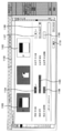
- FIGS. 1 and 2 are views showing the overall configuration of the automatic analyzer according to the present embodiment, and shows an outline when viewed from the upper part in FIG. 1 and from the front in FIG.
- the automatic analyzer 100 of this embodiment shown as an example in FIG. 1 accommodates a plurality of analysis modules 107 and 207 (two in this embodiment) and samples to be analyzed by these analysis modules 107 and 207. It is roughly composed of a sampler module 200 for transporting a sample rack on which one or more sample containers are mounted, and a control device 300 for controlling the overall operation of the automatic analyzer 100.
- the sample rack is loaded with one or more sample containers containing the samples to be subjected to qualitative / quantitative analysis in the analysis modules 107 and 207.
- the sample rack includes at least a sample rack (hereinafter, simply referred to as a sample rack 101) on which a sample container containing a sample (normal sample) to be analyzed with a normal priority is mounted, and the sample rack 101.
- a sample rack hereinafter, referred to as an emergency sample rack 101A when distinguished from the sample rack 101
- a sample rack hereinafter, referred to as an emergency sample rack 101A when distinguished from the sample rack 101
- the sampler module 200 is a module for transporting the sample rack 101 loaded into the automatic analyzer 100 between the analysis modules 107 and 207, and includes a sample rack supply unit 102, an emergency sample rack loading unit 112, a transport line 104, and an emergency.
- a sample rack standby area 113, a sample identification device 105, a rack rotor 106, a sample rack storage unit 103, and the like are provided.
- the transport line 104 is, for example, a belt conveyor type transport mechanism that reciprocates the sample rack 101 and the emergency sample rack 101A.
- the emergency sample rack loading section 112 is provided adjacent to the transport line 104 and is an area for loading the emergency sample rack 101A.
- the sample rack supply unit 102 is provided adjacent to the transfer line 104 on one end side of the transfer line 104 with respect to the emergency sample rack loading unit 112, and is an area for supplying the sample rack 101 of a normal sample.
- the sample rack storage unit 103 is provided adjacent to the transport line 104 on one end side of the transport line 104 with respect to the sample rack supply unit 102, and is an area for storing the sample rack 101.
- the emergency sample rack standby area 113 is provided on the transfer line 104 on the other end side of the transfer line 104 from the sample rack storage unit 103, and is an area for temporarily waiting the emergency sample rack 101A.
- the sample identification device 105 refers to the sample rack 101 and the RFID or bar provided on the sample container in order to inquire the analysis request information regarding the sample contained in the sample container mounted on the sample rack 101 transported on the transport line 104. It is a mechanism for reading and identifying an identification medium (not shown) such as a code.
- the rack rotor 106 is arranged at one end of the transport line 104.
- the rack rotor 106 has one or more slots 106a and 106b on which the sample rack 101 and the like can be mounted, and one end of the transport line 104 and one end of the dispensing lines 109 and 209 of the analysis modules 107 and 207, respectively. It is a mechanism for exchanging and receiving the sample rack 101 and the like with and from.
- the rack rotor 106 has a structure that rotates clockwise and counterclockwise, so that processing is started in the order in which the sample rack 101 is loaded, or the sample rack 101 having a high priority is loaded.
- the rotation operation is appropriately controlled so that the processing can be started before the sample rack 101 put in earlier.
- the analysis modules 107 and 207 are units that perform qualitative and quantitative analysis by sampling (dispensing) the samples contained in the sample container mounted on the sample rack 101, and the dispensing lines 109 and 209, respectively. , Specimen identification device 110, 210, reaction disc 118, 218, sample dispensing mechanism 108, 208, reagent disc 119, 219, reagent dispensing mechanism 120, 220, measuring unit (not shown), and the like.
- the dispensing lines 109 and 209 are reciprocating transferable transport mechanisms that pull the sample rack 101 from the sampler module 200 to the analysis modules 107 and 207 and deliver the sample rack 101 from the analysis modules 107 and 207 to the sampler module 200. Is adopted. For example, it is a belt conveyor type mechanism.
- a protrusion structure driven along the dispensing lines 109 and 209 is provided in advance in the sample rack 101. It is possible to adopt a configuration in which the portion is fitted into the recess and conveyed. Such a configuration is the same for the transport line 104.
- the sample identification devices 110 and 210 are provided adjacent to the other end side of the dispensing lines 109 and 209, and analysis request information for the sample stored in the sample rack 101 carried into the dispensing lines 109 and 209. This is a mechanism for reading and identifying identification media (not shown) such as RFID and barcodes provided on the sample rack 101 and the sample container in order to collate.
- the sample dispensing mechanism 108, 208 is a mechanism for dispensing a sample from the sample container of the sample rack 101 conveyed to the dispensing position on the dispensing lines 109, 209 to the reaction container of the reaction disks 118, 218.
- the reagent dispensing mechanisms 120 and 220 are mechanisms for dispensing the reagents contained in the reagent containers of the reagent disks 119 and 219 into the reaction vessels of the reaction disks 118 and 218.
- the measuring unit is a mechanism that performs qualitative and quantitative analysis by measuring the mixed solution (reaction solution) of the sample and reagent dispensed into the reaction vessel.
- the analysis module 107 is assumed to be a unit for biochemical examination, and the analysis module 207 is assumed to be a unit for immunological examination. In this case, the purpose and processing capacity of the examination are different.
- a measurement unit for measuring the electrolyte concentration can be provided in the analysis module 107, or a measurement unit for blood coagulation analysis or the like can be appropriately arranged in each module according to the specification environment.
- multiple analysis modules can be configured to maintain the same processing capacity with the same analysis module, and if only the purpose is different, multiple different analysis modules can be connected. It can be configured to be.
- the control device 300 is a device that controls the entire operation of the automatic analysis device 100 including the devices of the analysis modules 107 and 207 and the sampler module 200, and is a computer equipped with a CPU, a memory, and the like.
- the control device 300 includes a display unit 116, an input device 117, a storage unit 115, a control unit 114, and the like.
- the display unit 116 displays information such as input screens for various parameters and settings, analytical inspection data for initial inspection or re-inspection, measurement results, and information related to maintenance of the analysis modules 107 and 207 and the sampler module 200. It is a display device such as a liquid crystal display that displays various types of information. It should be noted that it may be composed of a touch panel type display device that also serves as an input device 117, which will be described later.
- the display unit 116 since the display unit 116 is located in the center of the automatic analyzer 100, the display unit 116 is configured to be rotatable toward the immunoassay module 207 side or the biochemical analysis module 107 side. .. Then, when it is tilted toward the immunoassay module 207 by a predetermined angle or more, it corresponds to the immunoassay module 207, and when it is tilted toward the biochemical analysis module 107 by a predetermined angle or more, it corresponds to the biochemical analysis module 107.
- the predetermined angle is set to 30 °.
- the display unit 116 of the present embodiment when the lower direction in FIG. 1 is set as the reference angle, which direction the display unit 116 is rotated in, the analysis module 107 or the analysis module 207, is rotated.
- An angle detector 121 for detecting an angle is provided.
- the input device 117 is composed of a keyboard and a mouse for inputting various data such as various parameters and settings, analysis request information, and instructions for starting analysis.
- the storage unit 115 is a semiconductor memory such as a flash memory that records the measurement result of the sample put into the automatic analyzer 100 and the analysis request information of the sample stored in the sample container mounted on each sample rack. It is a recording medium such as a magnetic disk such as an HDD. The storage unit 115 also records various parameters and set values for controlling the operation of each device in the automatic analyzer 100, various computer programs for executing various processes described later, and the like.
- the control unit 114 is a part that controls the entire operation of the automatic analysis device 100 including the control device 300, the analysis modules 107 and 207, and the sampler module 200, and is the above-mentioned CPU and the like.
- control unit 114 is the first screen on which the information of the analysis modules 107 and 207 is displayed based on the angle information of the display unit 116 detected by the angle detector 121.
- the second screen on which the information of only the specific analysis modules 107 and 207 is displayed is displayed separately.
- the remaining amount of the reagent required for analysis, the expiration date of the reagent, and the reagent information of at least one of the target modules using the reagent are displayed.
- the maintenance information including the maintenance progress status of the analysis modules 107 and 207 is displayed on the first screen, and the maintenance progress of the specific analysis modules 107 and 207 is displayed on the second screen. Display maintenance information including the status.
- control unit 114 causes the display unit 116 to display a setting screen for selecting a screen for displaying and separating the first screen and the second screen and a screen for not sorting.
- the above is the general configuration of the automatic analyzer 100.
- the sample analysis process by the automatic analyzer 100 as described above is generally executed in the following order.
- the operator gives an analysis instruction to the automatic analyzer 100 using the display unit 116 and the input device 117.
- the analysis instruction is stored in the storage unit 115 and transmitted to the target analysis module among the sampler module 200 and the analysis modules 107 and 207 via the control device 300.
- the target module performs the analysis operation as follows according to the received analysis instruction.
- the sampler module 200 sends the sample racks 101 installed in the sample rack supply unit 102 one by one onto the transport line 104 and carries them into the rack rotor 106.
- the sample rack 101 transported to the rack rotor 106 is transported to the dispensing line 109 of the analysis module 107 or the dispensing line 209 of the analysis module 207 according to the measurement items requested by the control device 300.
- the sample dispensing mechanism 108 and 208 performs a dispensing operation for each sample mounted on the sample rack 101.
- the sample dispensing mechanism 108 discharges the sucked sample into the reaction vessel on the reaction disk 118. Then, the reagent sucked from the reagent disk 119 by the reagent dispensing mechanism 120 is further added to the reaction vessel, and the mixture is stirred. After that, the absorbance and the like are measured by the measuring unit, and the measurement result is transmitted to the control unit 114 of the control device 300.
- the reaction vessel used for the analysis is washed with water, alkaline detergent, and acidic detergent dispensed from the washing mechanism (not shown) and used for the next analysis.
- the reagent sucked from the reagent disk 219 by the reagent dispensing mechanism 220 is discharged into the reaction vessel on the reaction disk 218, and the sample dispensing mechanism 208 is used for the reaction vessel. Add more sample and stir. Then, after performing processing such as magnetic separation as necessary, the measurement is performed by the measuring unit, and the measurement result is transmitted to the control unit 114 of the control device 300.
- the control unit 114 obtains the concentration of a specific component in the sample from the transmitted measurement result by arithmetic processing, displays the result on the display unit 116 or the like, or stores the result in the storage unit 115.
- the display unit 116 is installed on the upper surface of the sampler module 200.
- a top cover 141 is installed on the upper part of the biochemical analysis module 107
- a top cover 241 is installed on the upper part of the immunoassay module 207.
- the top covers 141 and 241 can be opened and closed, and the top view of the top cover in the opened state is shown in FIG.
- open / close detectors 142 and 242 for detecting the opening of the top covers 141 and 241 are installed in the apparatus.
- FIG. 3 is a diagram for explaining the outline of the first screen on the reagent information display screen
- FIG. 4 is a diagram for explaining the outline of the second screen for the analysis module 207
- FIG. 5 is a diagram for explaining the outline of the second screen for the analysis module 107. It is a figure to do.
- the reagent information display screen as shown in FIGS. 3 to 5 is displayed by pressing the reagent button (not shown) from the displayed global menu after logging in to the system.
- the reagent information display screen 400 of FIG. 3 is a screen for displaying information on reagents mounted on the analysis modules 107 and 207, and corresponds to the first screen.
- the names 402, the remaining amount 403, and the target module names 404 of all the reagents currently registered are displayed as a reagent list on the left side of the screen.
- the user opens the reagent information display screen 400 to check the remaining amount and expiration date of the registered reagent, register the reagent, and the like.
- the top covers 141 and 241 of the analysis modules 107 and 207 corresponding to the reagent are opened, the reagent is mounted, and the reagent registration button 415 in FIG. 3 is pressed to press the system. Register the reagent above.
- the display range when the reagent information display screen 400 is started is for all analysis modules, and the reagent information of both the immunoassay module 207 and the biochemical analysis module 107 is displayed on the screen.
- the reagent information of the non-target module is unnecessary, and if the non-target reagent information is displayed, it may lead to an erroneous operation. There is sex.
- combo box 405 as a method of switching the display range for each analysis module.
- all modules "biochemical analysis module”
- the reagent information display screen with the display unit 116 facing the front. 400 was opened, the combo box 405 was selected using the input device 117, and the information related to the target analysis module was selected as the display range. Then, after moving to the front of the target analysis module and exchanging the insufficient reagent, the input device 117 was operated again and the reagent was registered from the reagent registration button 415.
- control unit 114 is in a state where the display unit 116 is facing the front (for example, when the detection angle by the angle detector 121 is 0 °), as shown in FIG.
- the control unit 114 executes the control of displaying the information related to both the immunoassay module 207 and the biochemical analysis module 107 as the first screen, the time and effort for the user to move and press the combo box 405 is saved.
- FIG. 4 when the user instructs to display the reagent information display screen while the display unit 116 is rotated 30 ° or more toward the immunoassay module 207 as shown by the rotation operation 501, or the reagent information is already displayed.
- the control unit 114 displays only the reagent information corresponding to the immunoassay module 207 as shown in FIG.
- the reagent information display screen 500 is displayed on the display unit 116.
- the reagent information display screen 500 shown in FIG. 4 does not display the reagent information related to the biochemical analysis module 107, and only the reagent information related to the immunoassay module 207 is displayed. ..
- the reagent information display screen 500 corresponds to the second screen.
- the combo box 505 automatically switches to the contents of the immunoassay module 207, and the module reagent name 502, the remaining amount 503, and the target module name 504 also contain only information about the immunoassay module 207. Is displayed.
- FIG. 5 when the user gives an instruction to display the reagent information display screen in a state where the display unit 116 is rotated 30 ° or more toward the biochemical analysis module 107 as shown by the rotation operation 601 or already.
- the control unit 114 displays the reagent information corresponding to the biochemical analysis module 107 as shown in FIG.
- the reagent information display screen 600 in which only is displayed is displayed on the display unit 116.
- the combo box 605 automatically shows the contents of the biochemical analysis module 107 with the rotation, and the module reagent name 602, the remaining amount 603, and the target module name 604 are also related to the biochemical analysis module 107. Only information is displayed.
- FIG. 6 is a diagram for explaining the outline of the maintenance screen
- FIG. 7 is a diagram for explaining the outline of the first screen on the maintenance screen of the sample dispensing nozzle
- FIG. 8 is a diagram for explaining the outline of the first screen of the sample dispensing nozzle status monitor screen.
- FIG. 9 is a diagram for explaining the outline
- FIG. 9 is a diagram for explaining the outline of the second screen regarding the maintenance of the sample dispensing nozzle of the analysis module 207
- FIG. 10 is a diagram explaining the outline of the second screen regarding the maintenance of the sample dispensing nozzle of the analysis module 107. It is a figure explaining.
- the maintenance item display screen 700 shown in FIG. 6 is a screen displayed by pressing the maintenance button 701 located in the global area after logging in to the system.
- FIG. 6 from the list 702 showing the types of maintenance, maintenance items corresponding to one maintenance type focused by being selected by using the input device 117 are displayed in Table 704.
- Table 704. In the case of FIG. 6, since the check maintenance 703 is in focus, the items corresponding to the maintenance are displayed in Table 704.
- Table 704 displays module information 705 and 707, device information 706, name 708, and last implementation date and time 709 that are the targets of each maintenance item.
- module information 705 and 707 and the device information 706, ⁇ is described in the module column to be the target of each maintenance item for each column.
- the sample dispensing confirmation maintenance 710 the biochemical analysis module 107 and the immunoassay module 207 are used, and the control device 300 is not used.
- the final implementation date and time 709 is updated every time maintenance is performed. To carry out maintenance, click the sample dispensing confirmation maintenance 710 with the input device 117 and press the menu button 711 that appears by focusing on it, and select the pop-up menu 712 to go to each maintenance execution screen. Transition.
- the sample dispensing confirmation maintenance implementation screen 800 in FIG. 7 is a screen for setting and implementing the sample dispensing confirmation maintenance implementation.
- Sample dispensing confirmation maintenance can be set for each analysis module.
- the check box 801 corresponding to the control device 300 is displayed as an inactive state because maintenance is not performed.
- the check box 802 corresponding to the immunoassay module 207 and the check box 803 corresponding to the biochemical analysis module 107 are in an active state because maintenance can be performed.
- Settings for the immunoassay module 207 include a combo box 804 for the amount of dispensing, a combo box 805 for the type of plug, and a box 806 for specifying the number of dispensings.
- a combo box 807 for the dispensing amount there are a combo box 808 for the type of plug, and a box 809 for specifying the number of dispensings.
- the combo boxes 804,805,807,808 can be set using the combo box, and the designated boxes 806 and 809 can be set using the text box.
- the combo boxes 804 and 805 and the designated box 806 are inactive when the check box 802 is off, and the combo boxes 807 and 808 and the designated box 809 are inactive when the check box 803 is off.
- the sample dispensing confirmation maintenance is performed by pressing the execution button 810.
- sample dispensing confirmation maintenance is an interactive maintenance, and when the execution button 810 is pressed on the display unit 116, the state monitor screen 900 as shown in FIG. 8 is displayed, and an instruction from the system is given. Is displayed.
- column 902 is a detailed state 904 indicating the progress during maintenance of the immunoassay module 207, a specific instruction sentence 905, and an instruction confirmation button 906, and column 903 is a column 903 during maintenance of the biochemical analysis module 107.
- a detailed state 907 indicating the progress status, a specific instruction sentence 908, and an instruction confirmation button 909.
- the maintenance item display screen 700 shown in FIG. 6, the sample dispensing confirmation maintenance execution screen 800 shown in FIG. 7, and the state monitor screen 900 shown in FIG. 8 correspond to the first screen, as shown in each of the drawings. , Information relating to both the immunoassay module 207 and the biochemical analysis module 107 is displayed together.
- the pop-up menu 712 is selected by the user while the display unit 116 is rotated to the immunoassay module 207 side by 30 ° or more, or when the sample dispensing confirmation maintenance execution screen 800 is already displayed.
- the display unit 116 is rotated to the immunoassay module 207 side by 30 ° or more, as shown in FIGS. 9 and 10, the user does not remove the check box of the non-target analysis module, and FIG.
- the sample dispensing maintenance execution screen 1000 on which only the maintenance information corresponding to the immunoassay module 207 as shown in the above is displayed is displayed on the display unit 116 as the second screen.
- the check box 1002 corresponding to the immunoanalysis module 207 is turned on, the combo boxes 1004 and 1005 and the designated box 1006 are also activated, and the user changes the settings. Is possible.
- the check box 1003 reflecting the biochemical analysis module 107 is turned off, and the combo boxes 1007, 1008 and the designated box 1009 are also inactive. Therefore, the setting related to the biochemical analysis module 107 is not possible.
- the maintenance execution button 1010 When the maintenance execution button 1010 is pressed in the state shown in FIG. 9, maintenance is performed only on the immunoassay module 207, and the transition to the state monitor screen as shown in FIG. 8 is performed. In this case, the immunoassay module 207 is displayed. Only the maintenance state of is activated, and the detailed state 907, the instruction sentence 908, and the instruction confirmation button 909 for the biochemical analysis module 107 are not displayed, and the display is the same as that of the control module column in FIG.
- the control unit 114 displays only the maintenance information corresponding to the biochemical analysis module 107 as shown in FIG. 10. Sample dispensing maintenance The implementation screen 1100 is displayed on the display unit 116 as the second screen.
- sample dispensing maintenance execution screen 1100 unlike the sample dispensing maintenance implementation screen 1000 shown in FIG. 9, the check box 1103 corresponding to the biochemical analysis module 107 is turned on, the combo boxes 1107, 1108, and the designated boxes 1109. Is also activated, and the user can change the settings.
- the check box 1102 corresponding to the immunoassay module 207 is in the off state, and the combo boxes 1104 and 1105 and the designated box 1106 are also inactive, so that the setting related to the immunoassay module 207 is not possible.
- the screen in which the transition control between the first screen and the second screen described in this embodiment is suitable and the screen in which the transition control is not suitable are suitable.
- Examples of the screen to which the screen switching control described in this embodiment is suitable include the reagent information display screen described in FIGS. 3 to 5 and the maintenance screen described in FIGS. 7 to 10. On these screens, the user can operate the screen at the same time as operating the hardware, and the user can save the trouble of going back and forth between the display unit 116 and the target analysis module.
- FIG. 11 is a diagram illustrating an outline of the analysis setting screen.
- the analysis setting screen 1200 shown in FIG. 11 is a screen for setting the execution of liquid level detection and bubble detection of reagents during analysis. Since the timing of operating the analysis setting screen 1200 is before the start of analysis, in most cases, the user is located only in front of the display unit 116 even when the analysis is performed in a specific analysis module unit.
- the settings during analysis can be easily changed, leading to incorrect settings in the analysis.
- the user is located in front of the display unit 116, and it is very unlikely that the display unit 116 is tilted or moved from that state.
- transition control between the first screen and the second screen is not preferably applied to the screen for system setting such as the analysis setting screen 1200.
- the effect of transition control between the first screen and the second screen is particularly effective for screens such as reagent-related screens and maintenance-related screens, where the user is expected to be located in front of a specific analysis module. It can be said that it is effective.
- FIG. 12 is a diagram for explaining the outline of the screen transition setting screen
- FIG. 13 is a diagram for explaining the outline of the screen transition setting screen.
- lists 1301 and 1401 show major items in which the screens are roughly divided into items, for example, system screens and application screens. Etc., a total of 13 major items are displayed. When one of the items is clicked, it is focused and the list 1303, 1403 of the screen of the focused item is displayed.
- the focus can be applied by clicking the detailed setting item from the screen list, and the menu buttons 1304 and 1404 and the screen transition setting buttons 1305 and 1405 are displayed.
- the screen transition setting buttons 1305 and 1405 columns 1306 and 1406 are checked, and the screen of the item is a screen to which the transition control between the first screen and the second screen is applied. It is also possible to sort only the checked columns 1306 and 1406.
- the menu button 1304 is pressed and the screen transition setting button 1305 is pressed to check the location corresponding to the barcode reading setting screen in column 1306. Is attached, and the transition control between the first screen and the second screen is applied to the barcode reading setting screen.
- the menu button 1404 is pressed and the screen transition setting button 1405 is pressed, so that the barcode reading setting screen of column 1406 is pressed.
- the corresponding part is checked, and the transition control between the first screen and the second screen is applied to the reagent detail screen.
- FIG. 14 is a flowchart showing a flow from screen startup to displaying the first screen or the second screen.
- the screen to be adapted is displayed, or is started from the time when it is already displayed (step S301).
- Each of the following steps shall be performed at specific time intervals during the operation of the device.
- the angle information of the display unit 116 is acquired by the angle detector 121 (step S302).
- control unit 114 determines whether or not the display unit 116 is tilted to either the biochemical analysis module 107 side or the immunoassay module 207 side by 30 ° or more (step S303). When it is determined that none of the modules is tilted by 30 ° or more, the process proceeds to step S304, and the first screen, which is all module information, is displayed on the display unit 116 (step S304).
- step S303 when it is determined in step S303 that the display unit 116 is tilted to any module side by 30 ° or more, the control unit 114 determines whether the display unit 116 is tilted to the biochemical analysis module 107 side by 30 ° or more. (Step S305).
- the control unit 114 indicates information about the biochemical analysis module 107.
- the second screen is displayed (step S307).
- Section 114 displays a second screen showing information about the immunoassay module 207 (step S306).
- the automatic analyzer 100 of the first embodiment of the present invention described above includes two or more analysis modules 107 and 207 for analyzing a sample, a display unit 116 for displaying information of the analysis modules 107 and 207, and an analysis module 107.
- a first screen comprising a control unit 114 that controls the operation of the display unit 116 and the display unit 116, and the control unit 114 displays information on at least two analysis modules 107 and 207 based on the angle information of the display unit 116.
- the second screen in which the information of only the specific analysis modules 107 and 207 is displayed among the analysis modules 107 and 207 are displayed separately.
- the display range can be switched from a specific module target to a plurality of module targets depending on the situation, and the display range is related to a specific module. It is possible to instantly confirm the configuration from the information to the information related to the entire device.
- an automatic analyzer in which a plurality of types of analysis modules are integrated, it is suitable for an automatic analyzer that shares a display unit that displays information related to analysis corresponding to each analysis module.
- an angle detector 121 for detecting the angle of the display unit 116 is further provided, and the control unit 114 displays the first screen and the second screen separately based on the angle information detected by the angle detector 121. Since it is only necessary to tilt the display unit 116 by a predetermined angle or more, the second screen for displaying information about a specific module and the first screen for displaying the entire information are switched without performing complicated screen transition operations.
- the user works on a specific module without taking the trouble of moving from the front of the target module, less important information is not described, it is easy for the user to understand, and malfunction can be prevented.
- the first screen is displayed only by turning the display unit 116 to the front, so the act of manually selecting the display range from the combo box described above can be omitted, so the user The burden on the module can be significantly reduced.
- control unit 114 causes the display unit 116 to display a setting screen for selecting a screen for displaying the first screen and the second screen and a screen for not sorting, so that the user can optionally display the first screen and the second screen. It is possible to set a screen that transitions to the screen, and it is possible to turn off the screen transition setting for screens for which transition control is not suitable, such as the analysis setting screen, and the operation of the device. Can increase the stability of.
- control unit 114 displays the maintenance information including the maintenance progress status of the analysis modules 107 and 207 on the first screen, and displays the maintenance information including the maintenance progress status of the specific analysis modules 107 and 207 on the second screen. Display it.
- the user When performing maintenance for a specific analysis module, for example, when performing sample dispensing confirmation maintenance, installing racks on the dispensing lines 109 and 209 of each module, the user operates the target analysis module. It must be located in front of the target analysis module.
- the information of the immunoassay module 207 is to be known while using the biochemical analysis module 107, the information of the immunoassay module 207 can be easily obtained by turning the display unit 116 to the front. The effect of is also obtained.
- control unit 114 causes the user to display the remaining amount of the reagent required for the analysis, the expiration date of the reagent, and the reagent information of at least one of the target modules using the reagent on the first screen and the second screen.
- the information required for accessing a specific analysis module can be displayed on the large screen and the second screen, and the user's work can be assisted more effectively.
- the mode in which the control unit 114 executes the transition control based on the angle information of the display unit 116 has been described, but it is not limited to the angle information of the display unit 116 and is based on the position information of the display unit 116.
- the first screen on which the information of the two analysis modules 107 and 207 is displayed and the second screen on which the information of only the specific analysis modules 107 and 207 of the analysis modules 107 and 207 are displayed can be displayed separately.
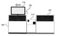
- FIG. 15 is a diagram illustrating a method of performing a transition to the second screen of the analysis module 207 in the automatic analyzer according to the second embodiment
- FIG. 16 is a diagram illustrating a method of performing a transition to the second screen of the analysis module 107. It is a figure.
- the display unit 116 is configured to be rotatable or, in addition, to be translateable to the analysis modules 107 and 207.
- the configuration that enables parallel movement may be a known configuration, and for example, a rail or the like can be used.
- a position detector 122 for detecting the position of the display unit 116 is provided, and the control unit 114 is the first screen based on the position information detected by the position detector 122. And the second screen are displayed separately.
- the display unit 116 when the display unit 116 was moved to the upper part of the immunoassay module 207 as shown in FIG. 15, it was moved to the upper part of the biochemical analysis module 107 so as to correspond to the immunoassay module 207. In some cases, it corresponds to the biochemical analysis module 107.
- the display unit 116 when the display unit 116 is located at the upper part of the sampler module 200, the information related to all the modules is displayed as the first screen, and when it is moved to the upper part of the immunoanalysis module 207, the immunoanalysis is performed as the second screen. Only the information related to the module 207 is displayed, and when it is moved to the upper part of the biochemical analysis module 107, only the information related to the biochemical analysis module 107 is displayed.
- the control unit 114 specifies the first screen on which the information of the two analysis modules 107 and 207 is displayed and the analysis modules 107 and 207 based on the position information of the display unit 116.
- the second screen in which the information of only the analysis modules 107 and 207 of the above is displayed is displayed separately.
- the position detector 122 for detecting the position of the display unit 116 is further provided, and the control unit 114 is provided by the position detector 122.
- the information of the two analysis modules 107 and 207 is displayed based on the information of the operation of the analysis modules 107 and 207 by the user, instead of the information about the display unit 116 as in the above-described first and second embodiments.
- the first screen and the second screen in which the information of only specific analysis modules 107 and 207 among the analysis modules 107 and 207 are displayed are displayed separately.
- the analysis modules 107 and 207 are a protection unit and an analysis unit that protect the analysis unit that analyzes the sample and the analysis unit such as the top covers 141 and 241 that cover the upper part of the analysis modules 107 and 207.
- it has an operation detection unit that detects that a predetermined operation has been performed on the protection unit.
- Examples of the operation detection unit include open / close detectors 142 and 242 for detecting the opening of the top covers 141 and 241 as shown in FIG. 2.
- the control unit 114 is the analysis module 107, respectively.
- the opening / closing of the top covers 141,241 of 207 is associated with the reagent information display screens 400, 500, 600 shown in FIG. The first screen and the second screen are displayed and separated.
- Reagent exchange is carried out by opening the top covers 141 and 241 of the analysis modules 107 and 207, which are the targets of the reagents to be exchanged, when the module state is standby.
- the user opens the reagent information display screen and operates the reagent registration button 415 to register the exchanged reagent.
- the top covers 141 and 241 are opened, and the reagent information display screen is displayed in this state. That is, if the reagent information display screen is displayed at the same time as the top covers 141 and 241 are opened, the user does not have to manually display the reagent information display screen. Further, since the displayed reagent information display screen is the screen of the corresponding analysis module, it is not necessary for the user to set the display range using the combo box as in the first embodiment.
- the reagent information display screen 600 shown in FIG. 5 is displayed, and the top of the immunoassay module 207 is displayed.
- the cover 141 is opened, the reagent information display screen 500 shown in FIG. 4 is displayed.
- top covers 141 and 241 of both the biochemical analysis module 107 and the immunoassay module 207 are opened within a predetermined time, or when one top cover is opened and the other top cover is also opened. In this case, it is desirable to display the reagent information display screen 400, which is the first screen.
- the timing at which the screen transition control based on the opening and closing of the top covers 141 and 241 is preferably applied is that the replacement work is completed unless it takes more time than necessary to replace the reagent. It is assumed that the time is within a predetermined time from the moment when the top covers 141 and 241 are opened. Therefore, when the predetermined time has passed, the first screen can be displayed even when the top covers 141 and 241 are continuously opened.
- the screen display It is not necessary to associate the screen display with the detection information that the top covers 141 and 241 are closed, but when it is detected that the top covers 141 and 241 are closed, the first screen is displayed as in the case where a predetermined time has elapsed. It can also be displayed.
- the control unit 114 displays the first screen and the second screen separately based on the states of the analysis modules 107 and 207 in addition to the opening / closing information detected by the opening / closing detectors 142 and 242. It shall be.
- the module state indicates the state related to the entire device, and multiple states such as standby in normal time and operation during analysis are defined. Then, in the predetermined module state, when the user performs a predetermined operation on the analysis module, a specific screen can be displayed.
- the control unit 114 displays the information of the two analysis modules 107 and 207 on the first screen and the analysis modules 107 and 207 based on the operation information of the analysis modules 107 and 207.
- the second screen in which information on only specific analysis modules 107 and 207 is displayed is displayed separately.
- the analysis modules 107 and 207 protect the analysis unit and the analysis unit that analyze the sample.
- An operation detection unit that detects that a predetermined operation has been performed on the unit, the analysis unit, or the protection unit, for example, the analysis modules 107 and 207 is a top cover 1411 that covers the upper part of the analysis modules 107 and 207 as a protection unit.
- control unit 114 displays the first screen and the second screen separately based on the states of the analysis modules 107 and 207 in addition to the operation information detected by the operation detection unit, thereby improving the convenience of the user. Can be improved.
- the opening / closing information of the top covers 141 and 241 is associated with the reagent information display screen has been described, but the user also operates the reaction disk 118, the reagent disk 119, the reagent dispensing mechanism 120, and the like. At that time, the screen corresponding to any mechanism can be displayed.
- the transition control between the first screen and the second screen of Examples 1 to 3 described above is not limited to the case where it is executed by the control unit 114 in the control device 300 in the automatic analyzer 100, and the automatic analysis is performed.
- LIS Laboratory Information System
- HIS Hospital Information System: hospital information system
- LIS and HIS function as a display system such as an automatic analyzer, and the first screen display signal displaying the information of the two analysis modules 107 and 207 and the specific analysis module of the analysis modules 107 and 207.
- the second screen display signal that displays information only for 107 and 207, the position information of the display unit 116 that displays the information of the analysis modules 107 and 207, the angle information of the display unit 116, and the operation information for the analysis modules 107 and 207. It will be output to the display unit 116 separately based on at least one of the information.
Abstract
表示部(116)の角度情報、表示部(116)の位置情報、および分析モジュール(107,207)に対する操作の情報のうちの少なくとも一つの情報に基づいて、少なくとも2つの分析モジュール(107,207)の情報が表示される第1画面と分析モジュール(107,207)のうち特定の分析モジュール(107,207)のみの情報が表示される第2画面とを表示し分ける。これにより、従来に比べて自動分析装置の状況に応じた画面をユーザにより正確かつ確実に提供することが可能となる。
Description
本発明は血液や血漿、血清、尿、その他の体液などの生体試料(以下、検体またはサンプルと称する)の定量、定性分析を行う自動分析装置、自動分析装置の表示システム、および自動分析装置における表示方法に関する。
検体の分析作業を行ないながら、表示装置で表示される情報を容易にかつ確実に確認する自動分析装置の一例として、特許文献1には、装置本体には、検体挿入部や分析部などの配列方向に沿ってレールが敷設されており、このレール上を表示装置が移動可能に取り付けられており、レールには、表示装置の現在位置を検出するための位置検出センサが複数個配列され、かかる位置検出センサのいずれかで検出された表示装置の現在位置を示す検出位置情報は制御装置に供給され、制御装置では、表示装置の現在位置に応じた装置本体での検体や試薬などの現在の状況を表わす状況情報画面が作成され、表示装置に供給される、ことが記載されている。
血液や尿の如き検体の定量、定性分析を自動で行う自動分析装置は、多くの患者検体を短時間で処理する必要のある病院や臨床検査センターを中心に多くの医療機関等で用いられている。
このような自動分析装置として、各施設において要求される処理能力に応じて大型、中型、小型の各種の自動分析装置が開発されている。
自動分析装置を支えるソフトウェア要素として、操作部と制御部用のソフトウェアがあり、操作部でユーザが依頼した項目や指定した設定を、分析時に制御部がユーザの指示に従って装置内の各機構を動作させる際に活躍している。
操作部の一つである表示部では、分析時における依頼項目の設定や、メンテナンス時のパラメータの設定等を決定できる他、試薬の残量や、メンテナンスの進行具合等、目視では分かりにくいモジュールの状態が表示され、可視化されている。このため、ユーザはこの表示部を通して装置の状態を把握しながら、分析のために必要な操作、作業を実行することができる。
また、ユーザは、設定時や分析時に、表示部の表示情報と装置の動作とを交互に見ながら操作することも可能となる。このとき、ユーザは、表示部の画面中のチェックボックスやコンボボックスを操作することで表示内容を変更することができる。
しかしながら、このような画面操作を、分析のために必要な操作や、作業と並行して行うことはユーザにとって複雑であり、ミスを招くおそれがある。
ここで、表示部におけるユーザの操作の手間を低減する技術に関し、特許文献1には、位置検出センサによって検出された表示部の現在位置、あるいはユーザの現在位置に対応して、制御部によって表示部に表示させる状況情報画面を変化させる構成が説明されている。
ところで、自動分析装置には、1つの分析機器とその分析機器の分析前動作を実行する機器とから構成される機器群を1モジュールとして、複数の分析モジュールを統合することにより処理能力等を向上させた統合型自動分析装置がある。
近年においては、接続される分析モジュールは同種のものに限られず、その種類は多用化している。例えば、血中のコレステロール等を測定する生化学分析モジュールと、感染症等を測定する免疫分析モジュールなどもあり、これら異種、あるいは同種の分析モジュールが複数接続される装置もある。これによって、大量の検体を測定するだけであったものから、多種項目の測定をするような流れになっている。
分析モジュールの複合化による測定項目の増加が進む一方で、このような複数モジュールから構成される自動分析装置では、測定項目に関する試薬情報など、表示部に示される情報量が増加しており、ユーザが一目で表示内容を押さえきれなくなる。
特に、複数のモジュールを統合した自動分析装置では、不必要な情報が表示された状態で特定のモジュール単体の作業をすることになるほど、誤操作を誘発するおそれがあるため、必要な情報のみを正確にユーザに提供する要求が非常に高くなっている。
また、表示項目によっては、情報の一部しか必要で無い状況も考えられる。一方で、例えば、分析中に試薬画面で特定のモジュールの試薬残量を把握し、その後で他のモジュールの試薬の状態をまとめて把握したい場合のように、試薬画面で複数の分析モジュールの情報を瞬時に把握したいケースが存在する。
特許文献1に記載された方法によれば、上述の通り、簡易的に特定のモジュールの情報のみを表示することができる。
しかしながら、特許文献1に記載の技術では、各モジュールに対して都度専用の画面を作成している。このため、上述のように、複数のモジュールの情報を把握したい場合には、ユーザは複数のモジュールの情報を含む画面を表示する操作が必要となるため、より簡易に複数のモジュールの情報を含む画面を表示するための構成が求められる。
すなわち、ユーザがそれぞれの場合に応じて表示範囲を適切に切り替える操作は複雑であり、装置およびシステム全体の構成を速やかに把握することがかえって困難となってしまうことから、負担を軽減する余地があることが明らかとなった。
本発明は、従来に比べて自動分析装置の状況に応じた画面をユーザにより正確かつ確実に提供することが可能な自動分析装置、自動分析装置の表示システム、および自動分析装置での表示方法を提供する。
本発明は、上記課題を解決する手段を複数含んでいるが、その一例を挙げるならば、検体の分析を行う少なくとも2つ以上の分析モジュールと、前記分析モジュールの情報を表示する表示部と、前記分析モジュールおよび前記表示部の動作を制御する制御部と、を備え、前記制御部は、前記表示部の位置情報、前記表示部の角度情報、前記分析モジュールに対する操作の情報のうちの少なくとも一つの情報に基づいて、少なくとも2つの前記分析モジュールの情報が表示される第1画面と前記分析モジュールのうち特定の前記分析モジュールのみの情報が表示される第2画面とを表示し分けることを特徴とする。
本発明によれば、従来に比べて自動分析装置の状況に応じた画面をユーザにより正確かつ確実に提供することができる。上記した以外の課題、構成および効果は、以下の実施例の説明により明らかにされる。
以下に本発明の自動分析装置、自動分析装置の表示システム、および自動分析装置における表示方法の実施例を、図面を用いて説明する。
<実施例1>
本発明の自動分析装置、自動分析装置の表示システム、および自動分析装置における表示方法の実施例1について図1乃至図14を用いて説明する。
本発明の自動分析装置、自動分析装置の表示システム、および自動分析装置における表示方法の実施例1について図1乃至図14を用いて説明する。
最初に、自動分析装置の全体構成の一例について図1および図2を用いて説明する。図1および図2は、本実施例に係る自動分析装置の全体構成を示す図であり、図1では上部から、図2では正面から見た場合の概略を示している。
図1に一例として示している本実施例の自動分析装置100は、複数(本実施例では2つ)の分析モジュール107,207と、これら分析モジュール107,207での分析対象となる検体を収容した1つ以上の検体容器を搭載する検体ラックを搬送するサンプラモジュール200と、自動分析装置100の全体の動作を制御する制御装置300と、から概略構成されている。
ここで、検体ラックには、分析モジュール107,207において定性・定量分析の対象となる検体が収容された1つ以上の検体容器が搭載されている。
検体ラックには、少なくとも、通常の優先度で分析が行われる検体(通常検体)を収容した検体容器が搭載された検体ラック(以降、単に検体ラック101と称する)と、その検体ラック101よりも分析測定の緊急度が高い緊急検体を収容した検体容器が搭載された検体ラック(以降、特に検体ラック101と区別する場合は緊急検体ラック101Aと記載する)とがある。
サンプラモジュール200は、自動分析装置100に投入される検体ラック101を分析モジュール107,207との間で搬送するモジュールであり、検体ラック供給部102、緊急検体ラック投入部112、搬送ライン104、緊急検体ラック待機エリア113、検体識別装置105、ラックロータ106、検体ラック収納部103、等を備えている。
搬送ライン104は、検体ラック101や緊急検体ラック101Aを往復搬送する、例えば、ベルトコンベヤタイプの搬送機構である。
緊急検体ラック投入部112は、搬送ライン104に隣接して設けられており、緊急検体ラック101Aを投入するための領域である。
検体ラック供給部102は、緊急検体ラック投入部112よりも搬送ライン104の一端側に搬送ライン104に隣接して設けられており、通常検体の検体ラック101を供給するための領域である。
検体ラック収納部103は、検体ラック供給部102よりも搬送ライン104の一端側に搬送ライン104に隣接して設けられており、検体ラック101を収納するための領域である。
緊急検体ラック待機エリア113は、検体ラック収納部103よりも搬送ライン104の他端側に搬送ライン104上に設けられており、緊急検体ラック101Aを一時的に待機させるための領域である。
検体識別装置105は、搬送ライン104を搬送される検体ラック101に搭載された検体容器に収容された検体に関する分析依頼情報を照会するために、検体ラック101および検体容器に設けられたRFIDやバーコードなどの識別媒体(図示省略)を読み取って識別する機構である。
ラックロータ106は、搬送ライン104の一端に配置さてれている。このラックロータ106は、検体ラック101等を搭載可能な1つ以上のスロット106a,106bを有しており、搬送ライン104の一端および分析モジュール107,207の分注ライン109,209の一端のそれぞれとの間で検体ラック101等の授受を行う機構である。
例えば、ラックロータ106は、時計回り、反時計回りに回転動作する構造になっており、検体ラック101が投入された順に処理を開始するように、あるいは、優先度の高い検体ラック101が投入された場合には、先に入れた検体ラック101よりも先に処理を開始することができるように、適宜その回転動作が制御される。
分析モジュール107,207は、検体ラック101に搭載された検体容器に収容された検体に対してサンプリング(分注)を行って定性・定量分析を行うユニットであり、それぞれ、分注ライン109,209、検体識別装置110,210、反応ディスク118,218、検体分注機構108,208、試薬ディスク119,219、試薬分注機構120,220、測定部(図示省略)、等を備えている。
分注ライン109,209は、サンプラモジュール200から分析モジュール107,207への検体ラック101の引き込み、および分析モジュール107,207からサンプラモジュール200への検体ラック101の引き渡しを行う往復動作可能な搬送機構を採用している。例えば、ベルトコンベヤタイプの機構である。
なお、分注ライン109,209としてベルトコンベヤタイプの搬送機構を採用した場合を例示しているが、分注ライン109,209に沿って駆動される突起構造物を検体ラック101に予め設けられた凹部に嵌合させて搬送する構成を採用することができる。このような構成は、搬送ライン104も同様である。
検体識別装置110,210は、分注ライン109,209の他端側に隣接して設けられており、分注ライン109,209に搬入された検体ラック101に収容されている検体に対する分析依頼情報を照合するために検体ラック101および検体容器に設けられたRFIDやバーコードなどの識別媒体(図示省略)を読み取って識別する機構である。
検体分注機構108,208は、分注ライン109,209上の分注位置に搬送された検体ラック101の検体容器から反応ディスク118,218の反応容器に検体を分注する機構である。
試薬分注機構120,220は、試薬ディスク119,219の試薬容器に収容された試薬を反応ディスク118,218の反応容器に分注する機構である。
測定部は、反応容器に分注された検体と試薬の混合液(反応液)の測定を行って定性・定量分析を行う機構である。
なお、本実施例では、分析モジュール107は生化学検査用のユニット、分析モジュール207は免疫検査用のユニットを想定しており、この場合、検査の目的や処理能力は異なる。
その他にも、分析モジュール107内に電解質濃度測定用の測定ユニットを設けたり、各モジュール内に仕様環境に応じて血液凝固分析用の測定ユニット等を適宜配置したりすることができる。
更に、目的(検査項目)が同一の場合は複数台の分析モジュールを同一の分析モジュールで処理能力も同じに維持する構成とすることができ、目的のみが異なる場合に異なる分析モジュールを複数台接続する構成とすることができる。
制御装置300は、分析モジュール107,207およびサンプラモジュール200の各機器を含め、自動分析装置100の全体の動作を制御する装置であり、CPUやメモリなどを備えたコンピュータである。
制御装置300は、表示部116、入力装置117、記憶部115、制御部114等から構成される。
表示部116は、各種パラメータや設定の入力画面、初回検査あるいは再検査の分析検査データ、測定結果等の情報を表示するとともに、分析モジュール107,207およびサンプラモジュール200のメンテナンスに関係する情報等の各種情報を表示する液晶ディスプレイ等の表示機器である。なお、後述する入力装置117を兼ねたタッチパネル式の表示装置から構成されたものとすることができる。
本実施例では、表示部116は自動分析装置100の中央に位置している為、表示部116の向きが、免疫分析モジュール207側、あるいは生化学分析モジュール107側へ回転可能に構成されている。そして、免疫分析モジュール207側へ所定角度以上傾けられた場合は免疫分析モジュール207と対応させ、生化学分析モジュール107へ所定角度以上傾けられた場合は生化学分析モジュール107に対応させる。一例として、所定角度を30°と設定する。
そのために、本実施例の表示部116には、図1中下方向を基準角度としたときに、表示部116が分析モジュール107と分析モジュール207のうちいずれの方向に回転されているか、その回転角度を検出する角度検出器121が設けられている。
入力装置117は、各種パラメータや設定、分析依頼情報、分析開始等の指示などの各種データを入力するためのキーボードやマウスで構成される。
記憶部115は、自動分析装置100内に投入された検体の測定結果、各検体ラックに搭載された検体容器に収容された検体の分析依頼情報等を記録しているフラッシュメモリ等の半導体メモリやHDD等の磁気ディスク等の記録媒体である。この記憶部115は、また、自動分析装置100内の各機器の動作の制御用の各種パラメータや設定値、後述する各種処理等を実行するための様々なコンピュータプログラム等を記録している。
制御部114は、制御装置300や分析モジュール107,207、サンプラモジュール200を含む自動分析装置100の全体の動作を制御する部分であり、上述のCPUなどである。
この制御部114は、本実施例においては、制御部114は、角度検出器121により検出された表示部116の角度情報に基づいて、分析モジュール107,207の情報が表示される第1画面と分析モジュール107,207のうち特定の分析モジュール107,207のみの情報が表示される第2画面とを表示し分ける。
また、これら第1画面および第2画面には、分析に必要な試薬の残量、試薬の有効期限、試薬を用いる対象モジュールのうち少なくともいずれかの試薬情報を表示させる。
更に、これら第1画面、第2画面のうち、第1画面に分析モジュール107,207のメンテナンスの進捗状況を含むメンテナンス情報を表示させ、第2画面に特定の分析モジュール107,207のメンテナンスの進捗状況を含むメンテナンス情報を表示させる。
また、制御部114は、第1画面と第2画面とを表示し分ける画面と、仕分けない画面とを選択する設定画面を表示部116に表示させる。
それらの詳細は、それぞれの図を用いて詳しくは後述する。
以上が自動分析装置100の一般的な構成である。
上述のような自動分析装置100による検体の分析処理は、一般的に以下の順に従い実行される。
オペレータは、表示部116や入力装置117を使って自動分析装置100に対して分析指示を与える。分析指示は、記憶部115に記憶されると共に、制御装置300を介してサンプラモジュール200および分析モジュール107,207のうち対象の分析モジュールに送信される。対象のモジュールは受信した分析指示に従い、次のように分析動作を行う。
サンプラモジュール200は、検体ラック供給部102に設置された検体ラック101を1ラックずつ搬送ライン104上に送り出し、ラックロータ106に搬入する。
ラックロータ106に搬送された検体ラック101は、制御装置300により依頼された測定項目に応じて、分析モジュール107の分注ライン109、あるいは分析モジュール207の分注ライン209に搬送される。
分注ライン109,209に検体ラック101が到着すると、検体ラック101に搭載された各試料に対して、検体分注機構108,208により分注動作が実施される。
測定項目が生化学項目の場合には、検体分注機構108は、吸引した試料を反応ディスク118上にある反応容器に吐出する。その後、その反応容器に対して試薬分注機構120により試薬ディスク119上から吸引した試薬を更に添加し、攪拌する。その後、測定部により吸光度等が測定され、測定結果が制御装置300の制御部114に送信される。
分析に使用された反応容器は、洗浄機構(図示省略)から分注される水やアルカリ性洗剤、および酸性洗剤で洗浄され、次の分析へ使用される。
また、測定項目が免疫項目の場合には、試薬分注機構220により試薬ディスク219上から吸引した試薬を反応ディスク218上の反応容器に吐出し、その反応容器に対して検体分注機構208により試料を更に添加し、攪拌する。その後、必要に応じて磁気分離などの処理を行った後、測定部により測定され、測定結果が制御装置300の制御部114に送信される。
制御部114は、送信された測定結果から演算処理によって試料内の特定成分の濃度を求め、結果を表示部116等に表示させる、あるいは記憶部115に記憶させるなどの処理を行う。
図2に示すように、サンプラモジュール200の上面に、表示部116が設置されている。
また、生化学分析モジュール107の上部にトップカバー141が、免疫分析モジュール207の上部にトップカバー241が設置してある。トップカバー141,241は開閉が可能であり、開蓋された状態の上面図が図1となる。また、装置内には、トップカバー141,241の開蓋を検出する開閉検出器142,242が設置されている。
次いで、本実施例の自動分析装置100の表示部116に表示される画面の表示制御の詳細について図3以降を用いて説明する。
最初に、表示部116に表示される試薬情報に関する第1画面や第2画面の詳細について図3乃至図5を用いて説明する。図3は試薬情報表示画面での第1画面の概要を説明する図、図4は分析モジュール207に関する第2画面の概要を説明する図、図5は分析モジュール107に関する第2画面の概要を説明する図である。
図3乃至図5に示すような試薬情報表示画面は、システムへログインした後に、表示されるグローバルメニューの中から、試薬ボタン(図示省略)を押下することで表示される。
図3の試薬情報表示画面400は、各分析モジュール107,207に搭載される試薬に関する情報を表示する画面であり、第1画面に相当する。
図3の試薬情報表示画面400では、現状登録されている全ての試薬の名称402、残量403、対象モジュール名称404が、画面左に試薬リストとして表示されている。
そして、試薬リストの中から、一つクリックし、フォーカスを当てた試薬401の登録されているモジュールの名称407、試薬カテゴリ408、搭載ポジション409、試薬使用優先順位410、試薬残量411、有効期限412、有効日数413、マスクの有無414等が、右表に試薬詳細リストとして表示される。
実際に、ユーザは、試薬情報表示画面400を開くことで、登録されている試薬の残量や有効期限の確認、試薬登録等を行う。
また、装置に試薬を新規登録、追加登録する際は、試薬に対応する分析モジュール107,207のトップカバー141,241を開き、試薬を搭載し、図3の試薬登録ボタン415を押下し、システム上へ試薬の登録を行う。
試薬情報表示画面400が立ち上がった際の表示範囲は、デフォルトでは全分析モジュールが対象であり、免疫分析モジュール207および生化学分析モジュール107、両者の試薬情報が画面上に表示される。
ここで、特定の分析モジュール107、あるいは分析モジュール207単体を対象として使用する場合では、対象外のモジュールの試薬情報は不要であり、対象外の試薬情報が表示されると、誤操作にも繋がる可能性がある。
現状、分析モジュールごとに表示範囲を切替える方法として、コンボボックス405が存在している。コンボボックス405では、項目として、「全モジュール」、「生化学分析モジュール」、「免疫分析モジュール」が割当てられており、選択された分析モジュールに対応する範囲の情報を表示させるフィルタリングを行うことができる。それによって、分析モジュールの食い違いによって生じる試薬登録における誤操作の防止も可能となる。
ここで、現状のシステムでは、特定の分析モジュールに係る試薬残量を確認して不足している試薬の追加登録を行う為には、表示部116が正面を向いている状態で試薬情報表示画面400を開き、コンボボックス405を入力装置117を用いて選択して対象分析モジュールに係る情報を表示範囲として選択していた。そのうえで、対象分析モジュールの手前へ動き、不足試薬の交換を行った後、入力装置117を再度操作して試薬登録ボタン415から、試薬の登録を行っていた。
また、この状態から、他のモジュールの試薬情報を確認する場合は、再び入力装置117の正面へ移動し、コンボボックス405から「全モジュール」項目をクリックしなければ、全てのモジュールの試薬情報を表示することができなかった。
これに対し、本発明では、制御部114は、表示部116が正面を向いている状態の場合(例えば、角度検出器121による検出角度が0°の場合)、図3に示されるように、免疫分析モジュール207および生化学分析モジュール107の両者に係る情報を第1画面として表示する制御を実行して、ユーザが移動し、コンボボックス405を押下する手間を省略する。
図4中、回転動作501で示すように表示部116が免疫分析モジュール207側へ30°以上回転されている状態でユーザから試薬情報表示画面を表示する指示がされた場合、もしくは既に試薬情報表示画面400が表示されている状態において回転動作501で示す方向に表示部116が回転された場合は、制御部114は、図4に示すような免疫分析モジュール207に対応する試薬情報のみが表示される試薬情報表示画面500を表示部116に表示させる。
図4に示す試薬情報表示画面500では、図3に示した試薬情報表示画面400と異なり、生化学分析モジュール107に関する試薬情報が表示されず、免疫分析モジュール207に関する試薬情報のみが表示されている。この試薬情報表示画面500が第2画面に相当する。
回転に伴って、図4に示すように、コンボボックス505は、自動で免疫分析モジュール207の内容に切り替わり、モジュール試薬名称502、残量503、対象モジュール名称504も、免疫分析モジュール207に関する情報のみが表示される。
また、図5中、回転動作601で示すように表示部116が生化学分析モジュール107側へ30°以上回転されている状態でユーザから試薬情報表示画面を表示する指示がされた場合、もしくは既に試薬情報表示画面400が表示されている状態で回転動作601で示す方向に表示部116が回転された場合は、制御部114は、図5に示すような生化学分析モジュール107に対応する試薬情報のみが表示される試薬情報表示画面600を表示部116に表示させる。
回転に伴って、図5に示すように、コンボボックス605は、自動で生化学分析モジュール107の内容を示し、モジュール試薬名称602、残量603、対象モジュール名称604も、生化学分析モジュール107に関する情報のみが表示される。
次いで、表示部116に表示されるメンテナンスに関する第1画面や第2画面の詳細について図6乃至図10を用いて説明する。図6はメンテナンス画面の概要を説明する図、図7は試料分注ノズルのメンテナンス画面での第1画面の概要を説明する図、図8は試料分注ノズルの状態モニタ画面の第1画面の概要を説明する図、図9は分析モジュール207の試料分注ノズルのメンテナンスに関する第2画面の概要を説明する図、図10は分析モジュール107の試料分注ノズルのメンテナンスに関する第2画面の概要を説明する図である。
図6に示すメンテナンス項目表示画面700は、システムログイン後、グローバルエリアに配置されている、メンテナンスボタン701が押下されることで表示される画面である。図6中、メンテナンスの種類を示すリスト702から、入力装置117を用いて選択されることでフォーカスが当てられた一つのメンテナンスタイプに対応するメンテナンス項目が表704に表示される。図6の場合であると、チェックメンテナンス703にフォーカスが当たっている為、メンテナンスに対応する項目が、表704に表示される。
表704には、各メンテナンス項目の対象となるモジュール情報705,707や装置情報706、名称708、最終実施日時709が表示されている。モジュール情報705,707や装置情報706は、列単位に各メンテナンス項目の対象となるモジュール欄に●が記載されている。
例えば、試料分注確認メンテナンス710は、生化学分析モジュール107および免疫分析モジュール207は使用し、制御装置300を使用しないことになる。また、最終実施日時709はメンテナンスを実施するごとに更新される。メンテナンスを実施する為には、試料分注確認メンテナンス710を入力装置117でクリックしてフォーカスを当てることで現れるメニューボタン711を押下し、ポップアップメニュー712を選択することによって、各メンテナンス実施画面へと遷移する。
図6の場合では、ポップアップメニュー712が押下されると、試料分注確認メンテナンスにフォーカスが当たっているので、図7で示される試料分注確認メンテナンス実施画面800が表示される。
図7の試料分注確認メンテナンス実施画面800は、試料分注確認メンテナンス実施における設定を行い、実施するための画面である。
試料分注確認メンテナンスの設定は分析モジュール単位で行うことができる。例えば、制御装置300に対応するチェックボックス801はメンテナンスが実施されない為に非活性状態として表示される。これに対し、免疫分析モジュール207に対応するチェックボックス802、および生化学分析モジュール107に対応するチェックボックス803は、メンテナンスを実施することが可能である為に活性状態になっている。
チェックボックス802,803をオフにすることで非活性となり、チェックボックスがオフとなったモジュールに対しては、メンテナンスは実施されない。
免疫分析モジュール207に対する設定としては、分注量のコンボボックス804、栓の種類のコンボボックス805、分注回数の指定ボックス806がある。生化学分析モジュール107に対する設定としても、同様に、分注量のコンボボックス807、栓の種類のコンボボックス808、分注回数の指定ボックス809がある。
コンボボックス804,805,807,808の設定はコンボボックスを用いて、指定ボックス806,809の設定はテキストボックスを用いて行うことができる。
また、コンボボックス804,805や指定ボックス806は、チェックボックス802がオフの場合に非活性となり、コンボボックス807,808や指定ボックス809は、チェックボックス803がオフの場合に非活性となる。設定終了後に、実施ボタン810を押下することで、試料分注確認メンテナンスが実施される。
また、試料分注確認メンテナンスは、対話型メンテナンスであることが望ましく、表示部116で実施ボタン810が押下されると、図8で示すような状態モニタ画面900が表示され、システムからの指示が表示される。
図8中、欄902は、免疫分析モジュール207のメンテナンス中の進行状況を示す詳細状態904、具体的な指示文905、指示確認ボタン906となり、欄903は、生化学分析モジュール107のメンテナンス中の進行状況を示す詳細状態907、具体的な指示文908、指示確認ボタン909である。
途中でメンテナンスを中止したい場合は、各々の分析モジュールのメンテナンス中止ボタン910,911を押下する。
図6で示すメンテナンス項目表示画面700や、図7で示す試料分注確認メンテナンス実施画面800、図8で示す状態モニタ画面900は第1画面に相当し、各々の図で示されているように、免疫分析モジュール207および生化学分析モジュール107の両者に係る情報が併せて表示される。
ここで、従来の自動分析装置では、特定の分析モジュール単体でメンテナンスを実施する場合、ユーザは、事前にチェックボックス801,802,803のチェックを外し、実行ボタン810を押下しなければならなかった。
これに対し、表示部116が免疫分析モジュール207側へ30°以上回転されている状態でユーザからポップアップメニュー712が選択された場合や、既に試料分注確認メンテナンス実施画面800が表示されている状態で表示部116が免疫分析モジュール207側へ30°以上回転された場合は、図9や図10に示すように、ユーザが、対象外の分析モジュールのチェックボックスを外す操作をせず、図9に示すような免疫分析モジュール207に対応するメンテナンス情報のみが表示される試料分注メンテナンス実施画面1000を第2画面として表示部116に表示させる。
図9に示す試料分注メンテナンス実施画面1000では、免疫分析モジュール207に対応するチェックボックス1002がオンの状態となり、コンボボックス1004,1005、指定ボックス1006も、活性状態となり、ユーザが設定変更することが可能となる。
一方、試料分注メンテナンス実施画面1000では、生化学分析モジュール107を反映するチェックボックス1003はオフの状態となり、コンボボックス1007,1008、指定ボックス1009も非活性となる。この為、生化学分析モジュール107に関する設定は不可となる。
図9に示す状態でメンテナンス実施ボタン1010が押下されると、免疫分析モジュール207に対してのみメンテナンスが実施され、図8で示すような状態モニタ画面へ遷移するが、この場合、免疫分析モジュール207のメンテナンス状態のみが活性状態となり、生化学分析モジュール107に対する詳細状態907、指示文908、指示確認ボタン909は表示されず、図8中、制御モジュールの欄と同様の表示となる。
また、図6で示すようなメンテナンス項目表示画面でも、第2画面として、免疫分析モジュール207に係るメンテナンス項目のみを表示することができる。
また、表示部116が生化学分析モジュール107側へ30°以上回転されている状態でユーザからポップアップメニュー712が選択された場合や、既に試料分注確認メンテナンス実施画面800が表示されている状態で表示部116が生化学分析モジュール107側へ30°以上回転された場合は、制御部114は、図10に示すような生化学分析モジュール107に対応するメンテナンス情報のみが表示される試料分注メンテナンス実施画面1100を第2画面として表示部116に表示させる。
試料分注メンテナンス実施画面1100では、図9に示した試料分注メンテナンス実施画面1000と異なり、生化学分析モジュール107に対応するチェックボックス1103がオンの状態となり、コンボボックス1107,1108、指定ボックス1109も活性状態となり、ユーザが設定変更することが可能となる。
一方、免疫分析モジュール207に対応するチェックボックス1102はオフの状態となり、コンボボックス1104,1105、指定ボックス1106も非活性となる為、免疫分析モジュール207に関する設定は不可となる。
図10に示す状態でメンテナンス実施ボタン1110が押下されると、生化学分析モジュール107に対してのみメンテナンスが実施され、図8で示すような状態モニタ画面へ遷移するが、この場合、免疫分析モジュール207に対する詳細状態904、指示文905、指示確認ボタン906は表示されない。
また、図6で示すようなメンテナンス項目表示画面や図8に示すような状態モニタ画面でも、第2画面として、生化学分析モジュール107に係るメンテナンス項目のみを表示することができる。
ここで、本実施例で説明している第1画面と第2画面との遷移制御が適している画面と、好適には適していない画面とが考えられる。本実施例で説明している画面の切り替え制御が適している画面としては、図3乃至図5で説明した試薬情報表示画面や図7乃至図10で説明したメンテナンス画面が挙げられる。これらの画面では、ユーザは、ハードウェアに対する操作と同時に画面操作も行うことができ、ユーザが表示部116と対象分析モジュール間を行き来する手間を省くことができる。
これに対し、好適には適用されない画面としては、システム自体の設定を行う画面が挙げられる。システム自体の設定画面は、ユーザが特定の分析モジュールの手前に位置している必要は無く、また、表示部116を動作させるのみで簡単に設定が変わってしまうと、誤操作を招く恐れがある。以下、図11を用いて説明する。図11は分析設定画面の概要を説明する図である。
図11に示す分析設定画面1200は、分析中における試薬の液面検知や泡検知の実施を設定する画面である。この分析設定画面1200を操作するタイミングは分析開始前となる為、特定の分析モジュール単位で分析を行う場合でも、ユーザは表示部116の前にのみ位置することがほとんどである。
分析設定画面1200に対して第1画面と第2画面との遷移制御を適用すると、例えば、表示部116を免疫分析モジュール207側へ傾けた場合、免疫分析モジュール207に関するチェックボックス1202が全てオンとなり、生化学分析モジュール107に関するチェックボックス1203が全てオフとなることが考えられる。
しかしながら、分析中の設定は、メンテナンスや試薬とは違って、容易に変更されることは分析における誤設定に繋がる。また、前述したように、ユーザは表示部116の正面に位置しており、その状態から表示部116を傾ける動作や移動する動作が行われる可能性は非常に低い。
そして、ユーザが免疫分析モジュール207の前、あるいは生化学分析モジュール107の前にいて当該モジュールの試薬情報などを確認している最中に、いずれのモジュールの分析中の設定を確認したい場合もある。このような場合に、分析中の設定が遷移制御によって切り替わることは望ましくない。
これらの理由から、分析設定画面1200等のシステム設定を行う画面は、好適には第1画面と第2画面との遷移制御が適用されないことが望ましい、と捉えられる。逆に言うと、第1画面と第2画面との遷移制御の効果は、試薬関連画面やメンテナンス関連画面のような、ユーザが特定の分析モジュールの手前に位置することが想定される画面に特に有効である、と言える。
そこで、第1画面と第2画面との遷移制御を適用する画面と適用しない画面の設定を行えることが望ましい。このような画面遷移設定画面について図12および図13を用いて説明する。図12は画面遷移設定画面の概要を説明する図、図13は画面遷移設定画面の概要を説明する図である。
図12に示す画面遷移設定画面1300や、図13に示す画面遷移設定画面1400のうち、リスト1301,1401には、画面を大きく項目分けした大項目が表示されており、例えばシステム画面やアプリケーション画面等、計13の大項目が表示される。そのうちの1つの項目がクリックされるとフォーカスされ、フォーカスがあてられた項目の画面のリスト1303,1403が表示される。
さらに画面リストの中から詳細設定項目をクリックすることでフォーカスをあてることができ、メニューボタン1304,1404および画面遷移設定ボタン1305,1405が表示される。画面遷移設定ボタン1305,1405を押下することで、列1306,1406にチェックがつき、当該項目の画面については第1画面と第2画面との遷移制御が適応される画面となる。また、チェックを入れた列1306,1406のみをソートすることも可能である。
図12では、システムのバーコード読取設定画面にフォーカスが当たっているので、メニューボタン1304が押下され、画面遷移設定ボタン1305が押下されることで、列1306のバーコード読取設定画面にあたる箇所にチェックがつき、バーコード読取設定画面に対して第1画面と第2画面との遷移制御が適応される。
また、図13の例であれば、試薬の試薬詳細画面にフォーカスが当たっているので、メニューボタン1404が押下され、画面遷移設定ボタン1405が押下されることで、列1406のバーコード読取設定画面にあたる箇所にチェックがつき、試薬詳細画面に対して第1画面と第2画面との遷移制御が適応される。
次に、本実施例に係る表示部116における表示方法について図14を参照して説明する。図14は画面立ち上げから第1画面または第2画面を表示するまでの流れを示すフローチャートである。
図14に示すように、適応対象となる画面を表示する、あるいは既に表示されている時点から開始される(ステップS301)。以下の各ステップは、装置の稼働中、特定時間間隔ごとに実行されるものとする。
まず、角度検出器121によって表示部116の角度情報を取得する(ステップS302)。
次いで、制御部114は、表示部116が生化学分析モジュール107側あるいは免疫分析モジュール207側のどちらかに30°以上傾けられているか否かを判定する(ステップS303)。いずれのモジュール側へも30°以上傾けられていないと判定されたときは処理をステップS304へ進め、表示部116に全モジュール情報である第1画面を表示する(ステップS304)。
これに対し、ステップS303においていずれかのモジュール側へ30°以上傾けられていると判定されたときは、制御部114は、表示部116が生化学分析モジュール107側へ30°以上傾いているか否かを判定する(ステップS305)。
生化学分析モジュール107側へ30°以上傾いていると判定されたときは、生化学分析モジュール107を単体で使用したい場合とみなされるので、制御部114は、生化学分析モジュール107に関する情報を示す第2画面を表示する(ステップS307)。
これに対し、生化学分析モジュール107側へ傾いていないと判定されたときは、免疫分析モジュール207側へ傾いている場合であり、免疫分析モジュール207を単体で使用したい場合とみなされるので、制御部114は、免疫分析モジュール207に関する情報を示す第2画面を表示する(ステップS306)。
次に、本実施例の効果について説明する。
上述した本発明の実施例1の自動分析装置100は、検体の分析を行う2つ以上の分析モジュール107,207と、分析モジュール107,207の情報を表示する表示部116と、分析モジュール107,207および表示部116の動作を制御する制御部114と、を備え、制御部114は、表示部116の角度情報に基づいて、少なくとも2つの分析モジュール107,207の情報が表示される第1画面と分析モジュール107,207のうち特定の分析モジュール107,207のみの情報が表示される第2画面とを表示し分ける。
このような構成によれば、第1画面と第2画面とが容易に遷移できることから、状況に応じて、表示範囲を特定のモジュール対象から複数のモジュール対象までの切り替え、また特定のモジュールに係る情報から装置全体に係る情報までの構成の確認を、瞬時に行うことが可能となる。
特に、複数種類の分析モジュールが統合された統合型自動分析装置において、各々の分析モジュールに対応した分析に関する情報を表示する表示部を共有化する自動分析装置に好適である。
特に、表示部116の角度を検出する角度検出器121を更に備え、制御部114は、角度検出器121により検出された角度情報に基づいて第1画面と第2画面とを表示し分けることで、表示部116を所定角度以上傾けるのみでよいため、煩雑な画面遷移操作を行うことなく、特定のモジュールに関する情報を表示する第2画面と全体の情報を表示する第1画面とが切り替わる。
このため、ユーザが対象モジュールの手前から移動する手間をかけることなく、特定のモジュールに対して作業を行う場合に、重要度が低い情報が記載されていない、ユーザにとってわかりやすく、誤動作を防止できる画面が表示された状態で作業することができる。したがって、例えば別モジュールへの試薬の取り違え等を防止するとともに、ユーザの負担を従来に比べて大幅に低減することができる。また、再び全モジュールの情報を確認したい場合は、表示部116を正面に向けるのみで第1画面が表示されるため、前述したコンボボックスから手動で表示範囲を選択する行為が省略できることから、ユーザの負担は大幅に軽減することができる。
更に、制御部114は、第1画面と第2画面とを表示し分ける画面と、仕分けない画面とを選択する設定画面を表示部116に表示させるため、ユーザが任意で第1画面と第2画面との遷移を行う画面を設定することが可能となり、分析設定画面のような、遷移制御を適応することが好適ではない画面に対して画面遷移設定をオフとすることができ、装置の運用の安定度を高めることができる。
また、制御部114は、第1画面に分析モジュール107,207のメンテナンスの進捗状況を含むメンテナンス情報を表示させ、第2画面に特定の分析モジュール107,207のメンテナンスの進捗状況を含むメンテナンス情報を表示させる。
特定の分析モジュールを対象としてメンテナンス実施する場合、例えば、試料分注確認メンテナンスを行う場合、各モジュールの分注ライン109,209にラックを設置する等、ユーザは対象分析モジュールに対して操作をしなくてはならず、対象分析モジュールの手前に位置することが想定される。
図9、図10のいずれの場合でも、表示部116を傾けるのみで対象モジュールのメンテナンス画面が表示されるため、ユーザが対象モジュールの手前から移動する手間が省略できる。再び全モジュールの情報を確認したい場合は、表示部116を制御部114側へ傾けることで第1画面が表示することができ、コンボボックスから手動で表示範囲を選択する行為も、省略できる。
更に、生化学分析モジュール107を使用している状態で、免疫分析モジュール207の情報を知りたい場合、表示部116を正面に向けることで、容易に免疫分析モジュール207の情報も知る事ができる、との効果も得られる。
更に、制御部114は、第1画面および第2画面に、分析に必要な試薬の残量、試薬の有効期限、試薬を用いる対象モジュールのうち少なくともいずれかの試薬情報を表示させることで、ユーザが特定の分析モジュールにアクセスする際に必要とされる情報を大画面および第2画面に表示することができ、ユーザの作業の補助をより効果的に行うことができる。
<実施例2>
本発明の実施例2の自動分析装置、自動分析装置の表示システム、および自動分析装置における表示方法について図15および図16を用いて説明する。
本発明の実施例2の自動分析装置、自動分析装置の表示システム、および自動分析装置における表示方法について図15および図16を用いて説明する。
なお、実施例1と同じ構成には同一の符号を示し、説明は省略する。以下の実施例においても同様とする。
実施例1では、制御部114は、表示部116の角度情報に基づいて遷移制御を実行する形態について説明したが、表示部116の角度情報に限られず、表示部116の位置情報に基づいて、2つの分析モジュール107,207の情報が表示される第1画面と分析モジュール107,207のうち特定の分析モジュール107,207のみの情報が表示される第2画面とを表示し分けることができる。
以下、図15および図16を用いて説明する。図15は実施例2に係る自動分析装置での分析モジュール207に関する第2画面への遷移を行う方法を説明する図、図16は分析モジュール107に関する第2画面への遷移を行う方法を説明する図である。
本実施例では、表示部116は、回転可能に替わり、あるいは加えて、分析モジュール107,207側へ平行移動可能に構成されている。平行移動可能とする構成は公知の構成でよく、例えばレールなどを用いることができる。
また、図15および図16に示すように、表示部116の位置を検出する位置検出器122を備えており、制御部114は、位置検出器122により検出された位置情報に基づいて第1画面と第2画面とを表示し分ける。
例えば、図15に示すように表示部116が免疫分析モジュール207の上部へ移動させた際には免疫分析モジュール207に対応させ、図16に示すように生化学分析モジュール107の上部へ移動させた際には生化学分析モジュール107に対応させる。
つまり、表示部116がサンプラモジュール200の上部に位置している場合は、第1画面として全てのモジュールに係る情報を表示し、免疫分析モジュール207の上部へ移動した際は第2画面として免疫分析モジュール207に関連する情報のみを表示し、生化学分析モジュール107の上部へ移動した際は生化学分析モジュール107に関連する情報のみを表示する。
その他の構成・動作は前述した実施例1の自動分析装置、自動分析装置の表示システム、および自動分析装置における表示方法と略同じ構成・動作であり、詳細は省略する。
本発明の実施例2のように、制御部114は、表示部116の位置情報に基づいて、2つの分析モジュール107,207の情報が表示される第1画面と分析モジュール107,207のうち特定の分析モジュール107,207のみの情報が表示される第2画面とを表示し分ける、特に、表示部116の位置を検出する位置検出器122を更に備え、制御部114は、位置検出器122により検出された位置情報に基づいて第1画面と第2画面とを表示し分けることによっても、前述した実施例1とほぼ同様な効果が得られる。
<実施例3>
本発明の実施例3の自動分析装置、自動分析装置の表示システム、および自動分析装置における表示方法について説明する。
本発明の実施例3の自動分析装置、自動分析装置の表示システム、および自動分析装置における表示方法について説明する。
本実施例は、上述の実施例1,2のように表示部116に関する情報ではなく、ユーザによる分析モジュール107,207に対する操作の情報に基づいて、2つの分析モジュール107,207の情報が表示される第1画面と分析モジュール107,207のうち特定の分析モジュール107,207のみの情報が表示される第2画面とを表示し分ける。
なお、本実施例では、実施例1,2のように表示部116に関する情報も用いて2つの分析モジュール107,207の情報が表示される第1画面と分析モジュール107,207のうち特定の分析モジュール107,207のみの情報が表示される第2画面とを表示し分けることができることは言うまでもない。
本実施例では、前提として、分析モジュール107,207は、検体の分析を行う分析部と、分析モジュール107,207の上部を覆うトップカバー141,241等の分析部を保護する保護部、分析部あるいは保護部に対して所定の操作が行われたことを検出する操作検出部、を有している。
操作検出部としては、例えば、図2に示したような、トップカバー141,241の開蓋を検出する開閉検出器142,242があげられ、この場合、制御部114は、各分析モジュール107,207のトップカバー141,241の開閉と図4等で示した試薬情報表示画面400,500,600とを関連付け、操作検出部である開閉検出器142,242により検出された開閉情報に基づいて第1画面と第2画面とを表示し分ける。
実施例1で説明した図4等に示される試薬情報表示画面400,500,600が表示される状況としては、試薬交換を行う場面が想定される。試薬交換は、モジュール状態がスタンバイの時に、交換する試薬の対象となる分析モジュール107,207のトップカバー141,241が開かれることで実施される。
そして、実際に試薬を交換した後、ユーザは試薬情報表示画面を開き、試薬登録ボタン415を操作して交換した試薬の登録を行う。
このような作業の流れを踏まえると、試薬交換を行う際は、トップカバー141,241が開かれている状態となり、この状態で試薬情報表示画面が表示されることになる。すなわち、トップカバー141,241が開かれると同時に試薬情報表示画面が表示されると、ユーザが手動で試薬情報表示画面を表示する必要が無くなる。さらに、表示される試薬情報表示画面が対応する分析モジュールの画面であることで、実施例1のように、ユーザがコンボボックスを用いて表示範囲の設定を行う必要がなくなる。
そこで、試薬情報表示画面400が表示されている際に、生化学分析モジュール107のトップカバー141が開かれた際は図5に示した試薬情報表示画面600を表示し、免疫分析モジュール207のトップカバー141が開かれた際は図4に示した試薬情報表示画面500を表示する。
また、生化学分析モジュール107および免疫分析モジュール207の両者のトップカバー141,241が所定時間内に開かれた場合、あるいは片方のトップカバーが開かれた状態でもう片方のトップカバーも開かれた場合は、第1画面である試薬情報表示画面400を表示することが望ましい。
更に、このようなトップカバー141,241の開閉に基づいた画面の遷移制御が好適に適応されるタイミングとしては、試薬の交換に必要以上に手間取らない限りは、交換作業が完了することから、トップカバー141,241が開かれた瞬間から所定時間内であることが想定される。そこで、所定時間を過ぎたときは、トップカバー141,241が開かれ続けている状態であっても、第1画面が表示されるようにすることができる。
なお、トップカバー141,241が閉蓋される検出情報とは画面の表示は関連付けを行う必要はないが、閉じられたことを検出したときは所定時間が経過した場合と同様に第1画面が表示されるものとすることもできる。
また、本実施例では、制御部114は、開閉検出器142,242により検出された開閉情報に加えて、分析モジュール107,207の状態に基づいて第1画面と第2画面とを表示し分けるものとする。モジュール状態は装置全体に係る状態を示し、通常時でスタンバイ、分析中はオペレーション等、複数の状態が定義されている。そして、所定のモジュール状態において、ユーザが分析モジュールに対して所定の操作を行った際に、特定の画面を表示するものとすることができる。
その他の構成・動作は前述した実施例1の自動分析装置、自動分析装置の表示システム、および自動分析装置における表示方法と略同じ構成・動作であり、詳細は省略する。
本発明の実施例3のように、制御部114は、分析モジュール107,207に対する操作の情報に基づいて、2つの分析モジュール107,207の情報が表示される第1画面と分析モジュール107,207のうち特定の分析モジュール107,207のみの情報が表示される第2画面とを表示し分けること、特には、分析モジュール107,207は、検体の分析を行う分析部、分析部を保護する保護部、分析部あるいは保護部に対して所定の操作が行われたことを検出する操作検出部、例えば、分析モジュール107,207は、保護部として分析モジュール107,207の上部を覆うトップカバー141,241、およびトップカバーの開蓋を検出する開閉検出器142,242を有しており、制御部114は、操作検出部により検出された操作情報に基づいて第1画面と第2画面とを表示し分けることによっても、前述した実施例1とほぼ同様な効果が得られる。
また、制御部114は、操作検出部により検出された操作情報に加えて、分析モジュール107,207の状態に基づいて第1画面と第2画面とを表示し分けることにより、ユーザの利便性を向上させることができる。
なお、本実施例では、トップカバー141,241の開閉情報と試薬情報表示画面とを関連付ける場合について説明したが、他にも反応ディスク118、試薬ディスク119、試薬分注機構120等をユーザが操作した際に、いずれの機構に対応する画面を表示することができる。
<その他>
なお、本発明は、上記の実施例に限定されるものではなく、様々な変形例が含まれる。上記の実施例は本発明を分かりやすく説明するために詳細に説明したものであり、必ずしも説明した全ての構成を備えるものに限定されるものではない。
なお、本発明は、上記の実施例に限定されるものではなく、様々な変形例が含まれる。上記の実施例は本発明を分かりやすく説明するために詳細に説明したものであり、必ずしも説明した全ての構成を備えるものに限定されるものではない。
また、ある実施例の構成の一部を他の実施例の構成に置き換えることも可能であり、また、ある実施例の構成に他の実施例の構成を加えることも可能である。また、各実施例の構成の一部について、他の構成の追加・削除・置換をすることも可能である。
例えば、上述の実施例1乃至実施例3の第1画面と第2画面との遷移制御は、自動分析装置100内の制御装置300内の制御部114により実行される場合に限られず、自動分析装置100の上位のシステムであるLIS(Laboratory Information System:検査室情報システム)や、臨床側で利用しているシステムであり、LIS20の上位に位置するシステムであるHIS(Hospital Information System:病院情報システム)においても実行することができる。
この場合、LISやHISは自動分析装置などの表示システムとして機能し、2つの分析モジュール107,207の情報が表示されている第1画面表示信号と、分析モジュール107,207のうち特定の分析モジュール107,207のみの情報を表示する第2画面表示信号とを、分析モジュール107,207の情報を表示する表示部116の位置情報、表示部116の角度情報、分析モジュール107,207に対する操作の情報のうちの少なくとも一つの情報に基づいて表示部116に対して出力し分けることになる。
100:自動分析装置
101:検体ラック
101A:緊急検体ラック
102:検体ラック供給部
103:検体ラック収納部
104:搬送ライン
105:検体識別装置
106:ラックロータ
106a,106b:スロット
107:生化学分析モジュール
108,208:検体分注機構
109,209:分注ライン
110,210:検体識別装置
112:緊急検体ラック投入部
113:緊急検体ラック待機エリア
114:制御部
115:記憶部
116:表示部
117:入力装置
118,218:反応ディスク
119,219:試薬ディスク
120,220:試薬分注機構
121:角度検出器
122:位置検出器
141,241:トップカバー
142,242:開閉検出器
200:サンプラモジュール
207:免疫分析モジュール
300:制御装置
400:試薬情報表示画面(第1画面)
401:試薬
402,502,602:名称
403,503,603:残量
404,504,604:対象モジュール名称
405,505,605:分析モジュール単位表示範囲切替えコンボボックス
407:対応分析モジュール名称
408:試薬カテゴリ
409:搭載ポジション
410:試薬使用優先順位
411:試薬残量
412:有効期限
413:有効日数
414:マスクの有無
415:試薬登録ボタン
500,600:試薬情報表示画面(第2画面)
501,601:回転動作
700:メンテナンス項目表示画面(第1画面)
701:メンテナンスボタン
702:リスト
703:チェックメンテナンス
704:確認メンテナンス項目一覧表
705:免疫分析モジュール情報
706:制御装置情報
707:生化学分析モジュール情報
708:確認メンテナンス項目名称
709:メンテナンス最終実施日時
710:試料分注確認メンテナンス
711:メニューボタン
712:ポップアップメニュー
800:試料分注確認メンテナンス実施画面(第1画面)
801:制御モジュールチェックボックス
802,1002,1102:免疫分析モジュールチェックボックス
803,1003,1103:生化学分析モジュールチェックボックス
804,1004,1104:分注量コンボボックス(免疫分析モジュール)
805,1005,1105:分注栓コンボボックス(免疫分析モジュール)
806,1006,1106:分注回数指定ボックス(免疫分析モジュール)
807,1007,1107:分注量コンボボックス(生化学分析モジュール)
808,1008,1108:分注栓コンボボックス(生化学分析モジュール)
809,1009,1109:分注回数指定ボックス(生化学分析モジュール)
810,1010,1110:実施ボタン
900:状態モニタ画面(第2画面)
902:免疫分析モジュールモニタ欄
903:生化学分析モジュールモニタ欄
904:詳細状態(免疫分析モジュール)
905:指示文(免疫分析モジュール)
906:指示確認ボタン(免疫分析モジュール)
907:詳細状態(生化学分析モジュール)
908:指示文(生化学分析モジュール)
909:指示確認ボタン(生化学分析モジュール)
910:メンテナンス中止ボタン(免疫分析モジュール)
911:メンテナンス中止ボタン(生化学分析モジュール)
1000,1100:試料分注メンテナンス実施画面(第2画面)
1200:分析設定画面
1202:免疫分析チェックボックス
1203:生化学分析チェックボックス
1300,1400:画面遷移設定画面(設定画面)
1301,1401:画面大項目リスト
1303,1403:画面詳細項目リスト
1304,1404:メニューボタン
1305,1405:画面遷移設定ボタン
1306,1406:画面遷移有効チェック列
Claims (11)
- 検体の分析を行う少なくとも2つ以上の分析モジュールと、
前記分析モジュールの情報を表示する表示部と、
前記分析モジュールおよび前記表示部の動作を制御する制御部と、を備え、
前記制御部は、前記表示部の位置情報、前記表示部の角度情報、前記分析モジュールに対する操作の情報のうちの少なくとも一つの情報に基づいて、少なくとも2つの前記分析モジュールの情報が表示される第1画面と前記分析モジュールのうち特定の前記分析モジュールのみの情報が表示される第2画面とを表示し分ける
ことを特徴とする自動分析装置。 - 請求項1に記載の自動分析装置において、
前記制御部は、前記第1画面と前記第2画面とを表示し分ける画面と、仕分けない画面とを選択する設定画面を前記表示部に表示させる
ことを特徴とする自動分析装置。 - 請求項1に記載の自動分析装置において、
前記表示部の角度を検出する角度検出器を更に備え、
前記制御部は、前記角度検出器により検出された角度情報に基づいて前記第1画面と前記第2画面とを表示し分ける
ことを特徴とする自動分析装置。 - 請求項1に記載の自動分析装置において、
前記表示部の位置を検出する位置検出器を更に備え、
前記制御部は、前記位置検出器により検出された位置情報に基づいて前記第1画面と前記第2画面とを表示し分ける
ことを特徴とする自動分析装置。 - 請求項1に記載の自動分析装置において、
前記分析モジュールは、前記検体の分析を行う分析部、前記分析部を保護する保護部、前記分析部あるいは前記保護部に対して所定の操作が行われたことを検出する操作検出部、を有しており、
前記制御部は、前記操作検出部により検出された操作情報に基づいて前記第1画面と前記第2画面とを表示し分ける
ことを特徴とする自動分析装置。 - 請求項5に記載の自動分析装置において、
前記分析モジュールは、前記保護部として前記分析モジュールの上部を覆うトップカバーを有し、前記操作検出部として前記トップカバーの開蓋を検出する開閉検出器を有している
ことを特徴とする自動分析装置。 - 請求項5に記載の自動分析装置において、
前記制御部は、前記操作検出部により検出された操作情報に加えて、前記分析モジュールの状態に基づいて前記第1画面と前記第2画面とを表示し分ける
ことを特徴とする自動分析装置。 - 請求項1に記載の自動分析装置において、
前記制御部は、前記第1画面および前記第2画面に、分析に必要な試薬の残量、前記試薬の有効期限、前記試薬を用いる対象モジュールのうち少なくともいずれかの試薬情報を表示させる
ことを特徴とする自動分析装置。 - 請求項1に記載の自動分析装置において、
前記制御部は、前記第1画面に前記分析モジュールのメンテナンスの進捗状況を含むメンテナンス情報を表示させ、前記第2画面に特定の前記分析モジュールのメンテナンスの進捗状況を含むメンテナンス情報を表示させる
ことを特徴とする自動分析装置。 - 検体の分析を行う少なくとも2つ以上の分析モジュールを備えた自動分析装置の表示部に対して表示信号を出力する表示システムであって、
少なくとも2つの前記分析モジュールの情報が表示されている第1画面表示信号と、前記分析モジュールのうち特定の前記分析モジュールのみの情報を表示する第2画面表示信号とを、前記分析モジュールの情報を表示する表示部の位置情報、前記表示部の角度情報、前記分析モジュールに対する操作の情報のうちの少なくとも一つの情報に基づいて出力し分ける
ことを特徴とする自動分析装置の表示システム。 - 検体の分析を行う少なくとも2つ以上の分析モジュールを備えた自動分析装置の表示部における表示方法であって、
少なくとも2つの前記分析モジュールの情報が表示されている第1画面表示信号と、前記分析モジュールのうち特定の前記分析モジュールのみの情報を表示する第2画面表示信号とを、前記分析モジュールの情報を表示する表示部の位置情報、前記表示部の角度情報、前記分析モジュールに対する操作の情報のうちの少なくとも一つの情報に基づいて表示し分ける
ことを特徴とする表示方法。
Priority Applications (4)
| Application Number | Priority Date | Filing Date | Title |
|---|---|---|---|
| JP2021569739A JP7329625B2 (ja) | 2020-01-07 | 2020-11-11 | 自動分析装置、自動分析装置の表示システム、および自動分析装置における表示方法 |
| EP20911316.6A EP4089417A4 (en) | 2020-01-07 | 2020-11-11 | AUTOMATIC ANALYSIS DEVICE, DISPLAY SYSTEM OF AN AUTOMATIC ANALYSIS DEVICE AND METHOD FOR CARRYING OUT THE DISPLAY IN AN AUTOMATIC ANALYSIS DEVICE |
| US17/789,834 US20230056397A1 (en) | 2020-01-07 | 2020-11-11 | Automatic analysis device, display system of automatic analysis device, and display method in automatic analysis device |
| CN202080090831.6A CN114902053A (zh) | 2020-01-07 | 2020-11-11 | 自动分析装置、自动分析装置的显示系统以及自动分析装置的显示方法 |
Applications Claiming Priority (2)
| Application Number | Priority Date | Filing Date | Title |
|---|---|---|---|
| JP2020001085 | 2020-01-07 | ||
| JP2020-001085 | 2020-01-07 |
Publications (1)
| Publication Number | Publication Date |
|---|---|
| WO2021140741A1 true WO2021140741A1 (ja) | 2021-07-15 |
Family
ID=76787856
Family Applications (1)
| Application Number | Title | Priority Date | Filing Date |
|---|---|---|---|
| PCT/JP2020/042016 WO2021140741A1 (ja) | 2020-01-07 | 2020-11-11 | 自動分析装置、自動分析装置の表示システム、および自動分析装置における表示方法 |
Country Status (5)
| Country | Link |
|---|---|
| US (1) | US20230056397A1 (ja) |
| EP (1) | EP4089417A4 (ja) |
| JP (1) | JP7329625B2 (ja) |
| CN (1) | CN114902053A (ja) |
| WO (1) | WO2021140741A1 (ja) |
Cited By (1)
| Publication number | Priority date | Publication date | Assignee | Title |
|---|---|---|---|---|
| WO2023008069A1 (ja) * | 2021-07-29 | 2023-02-02 | 株式会社日立ハイテク | 自動分析装置、および自動分析装置でのガイダンス方法 |
Citations (2)
| Publication number | Priority date | Publication date | Assignee | Title |
|---|---|---|---|---|
| JP2009250657A (ja) * | 2008-04-02 | 2009-10-29 | Hitachi High-Technologies Corp | 自動分析装置 |
| JP2010223810A (ja) | 2009-03-24 | 2010-10-07 | Hitachi High-Technologies Corp | 自動分析装置 |
Family Cites Families (6)
| Publication number | Priority date | Publication date | Assignee | Title |
|---|---|---|---|---|
| JP4755874B2 (ja) | 2005-09-27 | 2011-08-24 | シスメックス株式会社 | 検体分析装置、検体分析用処理コンピュータ、検体分析装置における操作用画面の表示方法、及び検体分析装置用処理コンピュータのためのコンピュータプログラム |
| WO2007086140A1 (ja) * | 2006-01-30 | 2007-08-02 | Shimadzu Corporation | 分析装置稼働状況表示システム |
| JP5606875B2 (ja) | 2010-10-29 | 2014-10-15 | シスメックス株式会社 | 検体処理装置及びコンピュータプログラム |
| JP5828728B2 (ja) * | 2011-09-28 | 2015-12-09 | 株式会社日立ハイテクノロジーズ | 自動分析装置 |
| EP3625803A4 (en) * | 2017-05-17 | 2020-06-03 | Siemens Healthcare Diagnostics, Inc. | ADVANCED REALITY ALARMS |
| GB2568932B (en) * | 2017-12-01 | 2022-07-13 | Applied Scientific Tech Uk Limited | Modular system |
-
2020
- 2020-11-11 WO PCT/JP2020/042016 patent/WO2021140741A1/ja unknown
- 2020-11-11 US US17/789,834 patent/US20230056397A1/en active Pending
- 2020-11-11 CN CN202080090831.6A patent/CN114902053A/zh active Pending
- 2020-11-11 EP EP20911316.6A patent/EP4089417A4/en active Pending
- 2020-11-11 JP JP2021569739A patent/JP7329625B2/ja active Active
Patent Citations (2)
| Publication number | Priority date | Publication date | Assignee | Title |
|---|---|---|---|---|
| JP2009250657A (ja) * | 2008-04-02 | 2009-10-29 | Hitachi High-Technologies Corp | 自動分析装置 |
| JP2010223810A (ja) | 2009-03-24 | 2010-10-07 | Hitachi High-Technologies Corp | 自動分析装置 |
Non-Patent Citations (1)
| Title |
|---|
| See also references of EP4089417A4 |
Cited By (1)
| Publication number | Priority date | Publication date | Assignee | Title |
|---|---|---|---|---|
| WO2023008069A1 (ja) * | 2021-07-29 | 2023-02-02 | 株式会社日立ハイテク | 自動分析装置、および自動分析装置でのガイダンス方法 |
Also Published As
| Publication number | Publication date |
|---|---|
| CN114902053A (zh) | 2022-08-12 |
| EP4089417A4 (en) | 2024-04-17 |
| EP4089417A1 (en) | 2022-11-16 |
| US20230056397A1 (en) | 2023-02-23 |
| JPWO2021140741A1 (ja) | 2021-07-15 |
| JP7329625B2 (ja) | 2023-08-18 |
Similar Documents
| Publication | Publication Date | Title |
|---|---|---|
| US8758684B2 (en) | Automatic analyzer | |
| EP2040081B1 (en) | Sample analyzer and error information displaying method | |
| US6579717B1 (en) | Specific solution handling method for calibration and quality control by automatic analytical apparatus | |
| US7185288B2 (en) | Operator interface module segmented by function in an automatic clinical analyzer | |
| EP2040080B1 (en) | Sample analyzer and method for analyzing samples | |
| JP4866808B2 (ja) | 自動分析装置 | |
| CN108700603B (zh) | 自动分析装置 | |
| WO1997009621A1 (fr) | Systeme automatique d'analyse et de visualisation | |
| JP5331056B2 (ja) | 自動分析装置 | |
| WO2021140741A1 (ja) | 自動分析装置、自動分析装置の表示システム、および自動分析装置における表示方法 | |
| JP6429753B2 (ja) | 自動分析装置及び自動分析方法 | |
| WO2020217720A1 (ja) | 自動分析装置および自動分析装置におけるメンテナンスガイド方法 | |
| WO2022176295A1 (ja) | 自動分析装置および自動分析装置の制御方法 | |
| EP4170350A1 (en) | Automatic analysis device | |
| EP3892999B1 (en) | Automatic analysis device | |
| CN110914692B (zh) | 自动分析装置及图像处理方法 | |
| JP2015049063A (ja) | 検体分析装置 | |
| WO2023162591A1 (ja) | 自動分析装置 | |
| JP2010266245A (ja) | 自動分析装置 | |
| US20240003924A1 (en) | Automatic Analysis System and Information Takeover Method in Automatic Analysis System | |
| WO2023008069A1 (ja) | 自動分析装置、および自動分析装置でのガイダンス方法 | |
| CN117836633A (zh) | 自动分析装置以及自动分析装置的运转方法 |
Legal Events
| Date | Code | Title | Description |
|---|---|---|---|
| 121 | Ep: the epo has been informed by wipo that ep was designated in this application |
Ref document number: 20911316 Country of ref document: EP Kind code of ref document: A1 |
|
| ENP | Entry into the national phase |
Ref document number: 2021569739 Country of ref document: JP Kind code of ref document: A |
|
| NENP | Non-entry into the national phase |
Ref country code: DE |
|
| ENP | Entry into the national phase |
Ref document number: 2020911316 Country of ref document: EP Effective date: 20220808 |