WO2021140661A1 - 固定子、電動機、天井扇風機、および固定子の製造方法 - Google Patents
固定子、電動機、天井扇風機、および固定子の製造方法 Download PDFInfo
- Publication number
- WO2021140661A1 WO2021140661A1 PCT/JP2020/000708 JP2020000708W WO2021140661A1 WO 2021140661 A1 WO2021140661 A1 WO 2021140661A1 JP 2020000708 W JP2020000708 W JP 2020000708W WO 2021140661 A1 WO2021140661 A1 WO 2021140661A1
- Authority
- WO
- WIPO (PCT)
- Prior art keywords
- stator
- teeth
- stator core
- resin
- insulator
- Prior art date
- Legal status (The legal status is an assumption and is not a legal conclusion. Google has not performed a legal analysis and makes no representation as to the accuracy of the status listed.)
- Ceased
Links
Images








Classifications
-
- H—ELECTRICITY
- H02—GENERATION; CONVERSION OR DISTRIBUTION OF ELECTRIC POWER
- H02K—DYNAMO-ELECTRIC MACHINES
- H02K15/00—Processes or apparatus specially adapted for manufacturing, assembling, maintaining or repairing of dynamo-electric machines
- H02K15/10—Applying solid insulation to windings, stators or rotors, e.g. applying insulating tapes
-
- H—ELECTRICITY
- H02—GENERATION; CONVERSION OR DISTRIBUTION OF ELECTRIC POWER
- H02K—DYNAMO-ELECTRIC MACHINES
- H02K3/00—Details of windings
- H02K3/32—Windings characterised by the shape, form or construction of the insulation
-
- Y—GENERAL TAGGING OF NEW TECHNOLOGICAL DEVELOPMENTS; GENERAL TAGGING OF CROSS-SECTIONAL TECHNOLOGIES SPANNING OVER SEVERAL SECTIONS OF THE IPC; TECHNICAL SUBJECTS COVERED BY FORMER USPC CROSS-REFERENCE ART COLLECTIONS [XRACs] AND DIGESTS
- Y02—TECHNOLOGIES OR APPLICATIONS FOR MITIGATION OR ADAPTATION AGAINST CLIMATE CHANGE
- Y02T—CLIMATE CHANGE MITIGATION TECHNOLOGIES RELATED TO TRANSPORTATION
- Y02T10/00—Road transport of goods or passengers
- Y02T10/60—Other road transportation technologies with climate change mitigation effect
- Y02T10/64—Electric machine technologies in electromobility
Definitions
- the present disclosure relates to a stator, a motor, a ceiling fan, and a method for manufacturing a stator arranged inside a tubular rotor.
- the motors include an inner rotor type motor in which a rotor is arranged inside a tubular stator and an outer rotor type motor in which a stator is arranged inside a tubular rotor as disclosed in Patent Document 1.
- a winding portion is formed by winding a winding around a tooth formed on the inner peripheral surface side of a tubular stator core.
- the winding portion is formed by winding the winding around the teeth formed on the outer peripheral surface side of the cylindrical or cylindrical stator core.
- winding the winding around the stator it tends to be easier to work by winding the winding around the teeth formed on the outer peripheral surface side. Therefore, the work of winding the winding around the stator used in the outer rotor type motor tends to be better than the work of winding the winding around the stator used in the inner rotor type motor.
- An insulator made of an insulating material is provided between the stator core and the winding to insulate between the stator core and the winding.
- the stator core and the insulator are integrally molded by covering the stator core with a mold and pouring resin into the gap between the mold and the stator core. ..
- the insulator can be formed on the surfaces of a plurality of teeth at once, so that it is effective in improving the production efficiency in the stator of the outer rotor type motor in which the area covered by the insulator tends to be large. It becomes a method.
- the resin does not sufficiently wrap around between the stator core and the mold, creating an area that is not covered by the insulator, or the thickness of the insulator becomes uneven. Is likely to occur. For example, when the resin is poured from one side in the axial direction of the stator core, the resin may not wrap around to the other side, which is the opposite side, and a region not covered by the insulator may be created.
- the present disclosure has been made in view of the above, and an object of the present disclosure is to obtain a stator that is less likely to cause an insulator construction defect.
- a plurality of teeth are formed in a cylindrical shape or a cylindrical shape, extending toward the outer peripheral direction and arranging along the circumferential direction, and a slot is provided between the teeth. It is provided with a stator core, an insulator that covers the teeth, and a winding portion formed by winding a winding around the teeth with an insulator interposed between the teeth.
- the insulator has a thick portion on the side surface of the teeth constituting the slot, which is thicker than the other portions.
- the stator according to the present disclosure has the effect of making it difficult for defective insulator construction to occur.
- Perspective view of the electric motor according to the first embodiment A perspective view showing the electric motor according to the first embodiment except for a part of the cover.
- Perspective view of the stator according to the first embodiment Perspective view of the stator core according to the first embodiment
- Top view showing the relationship between the stator core and the gate in the first embodiment.
- FIG. Sectional drawing which shows an example of the mold and the stator core in Embodiment 1.
- Cross-sectional view showing another example of the mold and the stator core according to the first embodiment.
- Partial enlarged view showing a modified example of the resin-filled portion in the first embodiment
- Partially enlarged perspective view showing a modified example of the stator core according to the first embodiment.
- stator The manufacturing method of the stator, the electric motor, the ceiling fan, and the stator according to the embodiment will be described in detail below based on the drawings. It should be noted that this embodiment does not limit this disclosure.
- FIG. 1 is a side view showing a schematic configuration of a ceiling fan according to a first embodiment.
- the ceiling fan 20 is hung from the ceiling and installed.
- the ceiling fan 20 includes an electric motor 25 and a plurality of wing portions 23 that rotate under the drive of the electric motor 25.
- the plurality of wing portions 23 are located on the circumference coaxial with the electric motor 25.
- the electric motor 25 and the plurality of wing portions 23 form the main body of the ceiling fan 20.
- the underside of the motor 25 is covered by a cover 24.
- the pipe 22 is a hollow rod.
- the pipe 22 supports the main body of the ceiling fan 20.
- the upper end of the pipe 22 is fixed to the ceiling at the fixing portion 21.
- the power supply line connected to the commercial power supply is passed through the inside of the pipe 22 from the ceiling and is connected to the power supply circuit of the motor 25.
- the ceiling, the commercial power supply, and the power supply circuit are not shown.
- FIG. 2 is a perspective view of the electric motor according to the first embodiment.
- FIG. 3 is a perspective view showing the motor according to the first embodiment except for a part of the cover.
- the electric motor 25 includes a rotor 4, a stator 6, a shaft 2, a bearing 3, and a cover 8.
- the stator 6 is arranged inside the cylindrical rotor 4.
- the shaft 2 is fixed to the stator 6 so as to extend along the central axis of the stator 6.
- the shaft 2 is inserted into and fixed to the inner ring of the bearing 3.
- the cover 8 is fixed to the outer ring of the bearing 3 and the rotor 4. With this configuration, the rotor 4 can rotate about the central axis of the cylinder.
- the wing portion 23 is connected to the rotor 4, so that the wing portion 23 rotates together with the rotor 4.
- FIG. 4 is a perspective view of the stator according to the first embodiment.
- the stator 6 includes a stator core 9, a main winding portion 10, and an auxiliary winding portion 11.
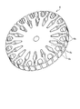
- FIG. 5 is a perspective view of the stator core according to the first embodiment.
- the stator core 9 has a cylindrical shape as a whole.
- a plurality of first teeth 9a extending outward in the radial direction are formed in the stator core 9.
- the plurality of first teeth 9a are formed side by side in the circumferential direction.
- the stator core 9 is provided with a second tooth 9b formed by bifurcating the tip of the first tooth 9a.
- windings are wound around the second teeth 9b that are adjacent to each other and extend from different first teeth 9a to form the main winding portion 10. That is, the space between the second teeth 9b branched from the same first teeth 9a is a slot on the outer peripheral side where the main winding portion 10 is provided. Further, the winding is wound around the first teeth 9a to form the auxiliary winding portion 11. That is, the space between the first teeth 9a is a slot on the inner peripheral side where the auxiliary winding portion 11 is provided.
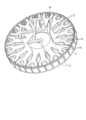
- FIG. 6 is a perspective view showing a state in which an insulator is formed on the stator core according to the first embodiment.
- the stator core 5 at least the region around which the winding is wound, that is, the outer peripheral surfaces of the first teeth 9a and the second teeth 9b are covered with an insulator 12 formed of an insulating resin.
- the insulator 12 provides insulation between the main winding portion 10 and the second teeth 9b and between the auxiliary winding portion 11 and the first teeth 9a.
- the insulator 12 has a thickness of, for example, 0.3 mm or more. If the thickness of the insulator 12 is thin, it is not possible to secure insulation between the main winding portion 10 and the second teeth 9b and between the auxiliary winding portion 11 and the first teeth 9a. On the other hand, if the insulator 12 is thick, the space of the slot becomes small, the main winding portion 10 and the auxiliary winding portion 11 become small, and the function as the motor 25 deteriorates.
- FIG. 7 is a perspective view of a mold used when forming an insulator on the stator according to the first embodiment.
- the mold 26 is formed with a recess 26a into which the stator core 9 is fitted.
- the recess 26a is formed in a size such that a gap is formed between the recess 26a and the stator core 9 in the region where the insulator 12 is formed.
- the insulator 12 is formed by sandwiching the stator core 9 with the mold 26 to cover the stator core 9 and pouring resin into the gap between the stator core 9 and the mold 26. For example, if a gap of 0.5 mm is formed between the stator core 9 and the recess 26a, an insulator 12 having a thickness of 0.5 mm is formed.
- the outer peripheral surface of the stator core 9 is held in close contact with the recess 26a of the mold 26.
- the mold 26 is formed with a gate that serves as an inflow path for resin into the gap between the stator core 9 and the mold 26.
- the gate communicates the outer peripheral surface of the mold 26 with the recess 26a via a runner described later, and the resin can be poured into the gap between the stator core 9 and the mold 26 through the gate and the runner.
- FIG. 8 is a perspective view showing the relationship between the stator core and the gate and runner in the first embodiment.
- FIG. 8 shows the shapes of the gate 27 and the runner 28 formed inside the mold 26 by showing the state in which the mold 26 is permeated.
- FIG. 9 is an enlarged partially enlarged perspective view of the gate portion shown in FIG.
- the mold 26 is, for example, a pin gate, three-plate type mold. In the case of resin molding using a general pingate mold, the resin is filled from the cavity side, so that the resin is filled from one side in the direction along the central axis with respect to the stator core 9. ..
- the surface of the stator core 9 facing the gate 27 side is referred to as a front surface
- the surface facing the opposite side to the front surface is referred to as a back surface. That is, it is necessary to make it easier for the resin that has flowed in from the front surface side of the stator core 9 to flow to the back surface side as well.
- the gates 27 in the example shown in FIG. 8 are provided at every other slot between the first teeth 9a in consideration of the symmetry of the resin flow, and a total of eight gates 27 are provided. ing.
- the number of gates may be 4 or 16 depending on the fluidity of the resin.
- FIG. 10 is a plan view showing the relationship between the stator core and the gate in the first embodiment.
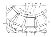
- FIG. 11 is a partially enlarged plan view of an enlarged gate portion of FIG.
- the insulator 12 has a resin at the base of the first teeth 9a, in a region between the first teeth 9a, and in a region on the radial center side of the auxiliary winding portion 11.
- a filling portion 12a is provided.
- the resin filling portion 12a is a thick portion formed with a thickness thicker than other portions in the insulator 12.
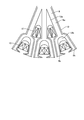
- the resin-filled portion 12a is formed by making the thickness of the insulator 12 along the radial direction at the base of the first teeth 9a thicker than other portions. More specifically, by making the radius of curvature Re of the side surface of the resin filling portion 12a larger than the radius of curvature Rd of the angle formed between the side surfaces of the first teeth 9a, the resin filling portion 12a is made larger than the other portions. It is thickly formed.
- the resin flows more easily than in other portions. Therefore, the resin easily flows to the back surface side of the stator core 9 through the resin filling portion 12a, and the construction failure of the insulator 12 due to the resin filling failure is less likely to occur. Further, since the insulator 12 is thickened and the resin filling portion 12a is provided at the portion where the auxiliary winding portion 11 is not wound, a space for forming the auxiliary winding portion 11 can be secured in the slot. Therefore, it is possible to prevent the function of the motor 25 from being deteriorated due to the formation of the resin filling portion 12a.
- the size of the resin filling portion 12a is represented by the diameter of the circle inscribed in the resin filling portion 12a, the size is 4 times or more and 10 times or less the thickness of the insulator 12 in the portion other than the resin filling portion 12a.
- the size of the resin filling portion 12a may be 2 mm to 5 mm.
- the resin filling portion 12a is formed by providing a resin filling flow path having a larger gap than other portions between the mold 26 and the stator core 9.
- the gate 27, which is the inlet of the resin into the gap between the mold 26 and the stator core 9, is provided at a position overlapping the resin filling portion 12a when the stator core 9 is viewed along the central axis. ing.
- the resin flowing in from the gate 27 smoothly flows into the resin filling portion 12a, so that the resin can flow more easily to the back surface side of the stator core 9 through the resin filling portion 12a. Therefore, since the resin can be evenly flowed on the front surface side and the back surface side of the stator core 9, the thickness of the insulator 12 on the front surface side and the back surface side can be easily formed uniformly on the entire surface.
- the stator core 9 when the stator core 9 is viewed along the central axis, if the gate 27 is provided at a position overlapping the stator core 9, the stator core 9 is moved by the injection pressure of the resin from the gate 27. It may be pushed and deformed, and the thickness of the insulator 12 may become thin on the back surface side.
- the gate 27 since the gate 27 is provided at a position overlapping the resin filling portion 12a, the insulator 12 having a uniform thickness is formed by suppressing the deformation of the stator core 9 due to the injection pressure of the resin. can do. In other words, the stator core 9 is not easily deformed even if the resin injection pressure of the gate 27 is increased. Therefore, the injection pressure of the resin can be increased to shorten the filling time of the resin, and the occurrence of thickness unevenness due to non-uniform solidification of the resin can be suppressed.
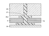
- FIG. 12 is a cross-sectional view showing an example of a mold and a stator core according to the first embodiment.
- FIG. 12 shows a cross section of the gate 27 portion cut by a plane parallel to the central axis of the stator core 9.
- the resin filling portion 12a is larger than the diameter of the gate 27, and as shown in FIG. 11, when viewed along the central axis of the stator core 9, the entire gate 27 is the resin filling portion 12a.
- An overlapping example is shown. In this case, a large amount of resin can be poured on the back surface side of the stator core 9. Therefore, it is effective when the diameter of the stator core 9 is large and the resin does not easily flow to the back surface.
- FIG. 13 is a cross-sectional view showing another example of the mold and the stator core according to the first embodiment.
- FIG. 13 shows a cross section of the gate 27 portion cut by a plane parallel to the central axis of the stator core 9.
- the resin filling portion 12a is smaller than the diameter of the gate 27, and as shown in FIG. 11, when viewed along the central axis of the stator core 9, a part of the gate 27 is a resin filling portion 12a.
- An example that does not overlap with is shown. In this case, since a lot of resin easily turns to the front surface side of the stator core 9, when the front surface of the stator core has a more complicated shape than the back surface, that is, to the front surface side of the stator core 9. It is effective when the resin does not flow easily.
- FIG. 14 is a partially enlarged view showing a modified example of the resin-filled portion in the first embodiment.
- a resin filling portion 12b may be provided at the root of the second teeth 9b.
- the gate 27 may be provided at both the position where it overlaps with the resin filling portion 12a and the position where it overlaps with the resin filling portion 12b, or the gate 27 may be provided only at a position where it overlaps with either one.
- the resin filling portion 12a may not be provided at the root of the first teeth 9a, and the resin filling portion 12b may be provided at the root of the second teeth 9b.
- the fluidity of the resin is better from the inner peripheral side to the outer peripheral side. Therefore, by providing the resin filling portion 12a at the base of the first teeth 9a, which is the side surface of the slot formed on the inner peripheral side, the flow of the resin in the outer peripheral direction is smoothed, and the insulator with a more uniform thickness is provided. Twelve can be formed.
- FIG. 15 is a partially enlarged perspective view showing a modified example of the stator core according to the first embodiment.
- the resin filling portions 12a and 12b may be provided by providing the notches 18 and 19 in the stator core 9. Since the thickness of the insulator 12 becomes thicker at the portions where the notches 18 and 19 are provided, the resin-filled portions 12a and 12b can be used.
- the insulator 12 can be thickened at the resin filling portions 12a and 12b without protruding to the slot side. Therefore, even if the resin filling portion 12a is provided at a position away from the root of the first teeth 9a like the notch 19 and where the auxiliary winding portion 11 is formed, the auxiliary winding portion is inside the slot. It is possible to secure a space for providing the eleven. Therefore, the degree of freedom in the position where the resin filling portion 12a is provided can be increased.
- the influence on the magnetic path is small because it is not the region where the auxiliary winding portion 11 or the main winding portion 10 is formed, and the notch 18 is formed. The formation is unlikely to lead to a decrease in the performance of the motor.
- the stator 6 illustrated in the first embodiment has 16 poles, and the angle formed by the first teeth 9a is an acute angle of 22.5 degrees, and it is difficult to wind the winding to the very limit of the center side.
- the resin filling portion 12a in the region on the center side of the slot, the uniformity of the resin flow is improved without affecting the formation of the auxiliary winding portion 11 or the magnetic path. can do.
- the motor 25 described above is suitable for use in the ceiling fan 20 as shown in FIG. Since the ceiling fan 20 is installed suspended from the ceiling and is ventilated by rotating blades of about 1 m, a larger load is applied to the motor 25 as compared with a household fan, and the electric fan 20 is always operated for ventilation. , Long-term reliability is required. By integrally molding the insulator 12 into the stator core 9 by resin molding, the long-term reliability of the electric motor 25, that is, the long-term reliability of the ceiling fan 20 can be ensured.
- the first teeth 9a and the second teeth 9b may not be formed on the stator core 9. Even in the stator core 9 in which only the first teeth 9a are formed, the effect of preventing poor construction of the insulator 12 can be obtained by providing the resin filling portion 12a.
- the configuration shown in the above embodiments is an example, and can be combined with another known technique, can be combined with each other, and does not deviate from the gist. It is also possible to omit or change a part of the configuration.
Landscapes
- Engineering & Computer Science (AREA)
- Power Engineering (AREA)
- Manufacturing & Machinery (AREA)
- Insulation, Fastening Of Motor, Generator Windings (AREA)
- Manufacture Of Motors, Generators (AREA)
- Iron Core Of Rotating Electric Machines (AREA)
Priority Applications (2)
| Application Number | Priority Date | Filing Date | Title |
|---|---|---|---|
| PCT/JP2020/000708 WO2021140661A1 (ja) | 2020-01-10 | 2020-01-10 | 固定子、電動機、天井扇風機、および固定子の製造方法 |
| JP2021569702A JP7292430B2 (ja) | 2020-01-10 | 2020-01-10 | 固定子の製造方法 |
Applications Claiming Priority (1)
| Application Number | Priority Date | Filing Date | Title |
|---|---|---|---|
| PCT/JP2020/000708 WO2021140661A1 (ja) | 2020-01-10 | 2020-01-10 | 固定子、電動機、天井扇風機、および固定子の製造方法 |
Publications (1)
| Publication Number | Publication Date |
|---|---|
| WO2021140661A1 true WO2021140661A1 (ja) | 2021-07-15 |
Family
ID=76787799
Family Applications (1)
| Application Number | Title | Priority Date | Filing Date |
|---|---|---|---|
| PCT/JP2020/000708 Ceased WO2021140661A1 (ja) | 2020-01-10 | 2020-01-10 | 固定子、電動機、天井扇風機、および固定子の製造方法 |
Country Status (2)
| Country | Link |
|---|---|
| JP (1) | JP7292430B2 (https=) |
| WO (1) | WO2021140661A1 (https=) |
Citations (6)
| Publication number | Priority date | Publication date | Assignee | Title |
|---|---|---|---|---|
| JPH11341714A (ja) * | 1998-05-28 | 1999-12-10 | Toshiba Corp | モータのステータ |
| JP2004208386A (ja) * | 2002-12-25 | 2004-07-22 | Hitachi Ltd | 回転電機及び電動車両並びに樹脂のインサート成形方法 |
| JP2012200116A (ja) * | 2011-03-23 | 2012-10-18 | Panasonic Corp | 電動機 |
| JP2015002582A (ja) * | 2013-06-13 | 2015-01-05 | 日産自動車株式会社 | ロータ鉄心へのマグネット固定装置及び固定方法 |
| JP2015188291A (ja) * | 2014-03-27 | 2015-10-29 | パナソニックIpマネジメント株式会社 | 外転型電動機およびそれを搭載した天井扇 |
| JP2017169397A (ja) * | 2016-03-17 | 2017-09-21 | 三菱電機株式会社 | 回転電機の絶縁積層板構造体およびその製造方法 |
-
2020
- 2020-01-10 WO PCT/JP2020/000708 patent/WO2021140661A1/ja not_active Ceased
- 2020-01-10 JP JP2021569702A patent/JP7292430B2/ja active Active
Patent Citations (6)
| Publication number | Priority date | Publication date | Assignee | Title |
|---|---|---|---|---|
| JPH11341714A (ja) * | 1998-05-28 | 1999-12-10 | Toshiba Corp | モータのステータ |
| JP2004208386A (ja) * | 2002-12-25 | 2004-07-22 | Hitachi Ltd | 回転電機及び電動車両並びに樹脂のインサート成形方法 |
| JP2012200116A (ja) * | 2011-03-23 | 2012-10-18 | Panasonic Corp | 電動機 |
| JP2015002582A (ja) * | 2013-06-13 | 2015-01-05 | 日産自動車株式会社 | ロータ鉄心へのマグネット固定装置及び固定方法 |
| JP2015188291A (ja) * | 2014-03-27 | 2015-10-29 | パナソニックIpマネジメント株式会社 | 外転型電動機およびそれを搭載した天井扇 |
| JP2017169397A (ja) * | 2016-03-17 | 2017-09-21 | 三菱電機株式会社 | 回転電機の絶縁積層板構造体およびその製造方法 |
Also Published As
| Publication number | Publication date |
|---|---|
| JP7292430B2 (ja) | 2023-06-16 |
| JPWO2021140661A1 (https=) | 2021-07-15 |
Similar Documents
| Publication | Publication Date | Title |
|---|---|---|
| CN109194037B (zh) | 一种隔离电机定子、转子所在空间的油冷电机 | |
| JP5904282B2 (ja) | コイル、回転電機、及びコイルの製造方法 | |
| CN111279585A (zh) | 转子以及用于制造转子的方法 | |
| TWI678054B (zh) | 軸向間隙型旋轉電機及其製造方法 | |
| WO2013080597A1 (ja) | 電動機の固定子および永久磁石式回転電機 | |
| US10536061B2 (en) | Method for manufacturing stator of rotary electric machine | |
| US9954415B2 (en) | Rotor for brushless motor | |
| US10153673B2 (en) | Production method for rotating electrical machine | |
| US20130280090A1 (en) | Fan device | |
| US20190052157A1 (en) | Rotor assembly, motor including rotor assembly, and method for manufacturing rotor assembly | |
| CN106230152B (zh) | 转子铁芯组件、转子及自起动永磁同步电机 | |
| CN203180736U (zh) | 单相感应马达 | |
| WO2018138852A1 (ja) | 回転電機 | |
| CN120836133A (zh) | 具有定子和优化的极靴冷却的轴流式机器 | |
| WO2021140661A1 (ja) | 固定子、電動機、天井扇風機、および固定子の製造方法 | |
| JPWO2018142463A1 (ja) | アキシャルギャップ型回転電機 | |
| JP2017153346A (ja) | モータ、並びにその外側磁気コア及び内側磁気コア | |
| CN113364158B (zh) | 一种便于外圆面加工的电机定子、电机及其加工装配工艺 | |
| TWI620398B (zh) | 定子、電動機、定子之製造方法及電動機之製造方法 | |
| JP3639130B2 (ja) | モールド電動機およびその製造方法 | |
| JPWO2021140661A5 (https=) | ||
| CN107181334A (zh) | 风机定子及其风机 | |
| KR100981744B1 (ko) | 연료펌프용 3상 모터의 고정자 구조 | |
| JP2022184651A (ja) | Pmモータの製造方法及びpmモータ | |
| CN222996302U (zh) | 混合转子以及电机 |
Legal Events
| Date | Code | Title | Description |
|---|---|---|---|
| 121 | Ep: the epo has been informed by wipo that ep was designated in this application |
Ref document number: 20911922 Country of ref document: EP Kind code of ref document: A1 |
|
| ENP | Entry into the national phase |
Ref document number: 2021569702 Country of ref document: JP Kind code of ref document: A |
|
| NENP | Non-entry into the national phase |
Ref country code: DE |
|
| 122 | Ep: pct application non-entry in european phase |
Ref document number: 20911922 Country of ref document: EP Kind code of ref document: A1 |