WO2021140579A1 - 瞳孔検出装置、視線検出装置、搭乗者監視システム及び瞳孔検出方法 - Google Patents
瞳孔検出装置、視線検出装置、搭乗者監視システム及び瞳孔検出方法 Download PDFInfo
- Publication number
- WO2021140579A1 WO2021140579A1 PCT/JP2020/000213 JP2020000213W WO2021140579A1 WO 2021140579 A1 WO2021140579 A1 WO 2021140579A1 JP 2020000213 W JP2020000213 W JP 2020000213W WO 2021140579 A1 WO2021140579 A1 WO 2021140579A1
- Authority
- WO
- WIPO (PCT)
- Prior art keywords
- evaluation value
- unit
- image
- pupil
- evaluation
- Prior art date
- Legal status (The legal status is an assumption and is not a legal conclusion. Google has not performed a legal analysis and makes no representation as to the accuracy of the status listed.)
- Ceased
Links
Images














Classifications
-
- G—PHYSICS
- G06—COMPUTING OR CALCULATING; COUNTING
- G06T—IMAGE DATA PROCESSING OR GENERATION, IN GENERAL
- G06T7/00—Image analysis
- G06T7/70—Determining position or orientation of objects or cameras
- G06T7/73—Determining position or orientation of objects or cameras using feature-based methods
- G06T7/74—Determining position or orientation of objects or cameras using feature-based methods involving reference images or patches
-
- A—HUMAN NECESSITIES
- A61—MEDICAL OR VETERINARY SCIENCE; HYGIENE
- A61B—DIAGNOSIS; SURGERY; IDENTIFICATION
- A61B5/00—Measuring for diagnostic purposes; Identification of persons
- A61B5/16—Devices for psychotechnics; Testing reaction times ; Devices for evaluating the psychological state
- A61B5/18—Devices for psychotechnics; Testing reaction times ; Devices for evaluating the psychological state for vehicle drivers or machine operators
-
- A—HUMAN NECESSITIES
- A61—MEDICAL OR VETERINARY SCIENCE; HYGIENE
- A61B—DIAGNOSIS; SURGERY; IDENTIFICATION
- A61B3/00—Apparatus for testing the eyes; Instruments for examining the eyes
- A61B3/10—Objective types, i.e. instruments for examining the eyes independent of the patients' perceptions or reactions
- A61B3/113—Objective types, i.e. instruments for examining the eyes independent of the patients' perceptions or reactions for determining or recording eye movement
-
- G—PHYSICS
- G06—COMPUTING OR CALCULATING; COUNTING
- G06V—IMAGE OR VIDEO RECOGNITION OR UNDERSTANDING
- G06V10/00—Arrangements for image or video recognition or understanding
- G06V10/40—Extraction of image or video features
- G06V10/60—Extraction of image or video features relating to illumination properties, e.g. using a reflectance or lighting model
-
- G—PHYSICS
- G06—COMPUTING OR CALCULATING; COUNTING
- G06V—IMAGE OR VIDEO RECOGNITION OR UNDERSTANDING
- G06V20/00—Scenes; Scene-specific elements
- G06V20/50—Context or environment of the image
- G06V20/59—Context or environment of the image inside of a vehicle, e.g. relating to seat occupancy, driver state or inner lighting conditions
- G06V20/597—Recognising the driver's state or behaviour, e.g. attention or drowsiness
-
- G—PHYSICS
- G06—COMPUTING OR CALCULATING; COUNTING
- G06V—IMAGE OR VIDEO RECOGNITION OR UNDERSTANDING
- G06V40/00—Recognition of biometric, human-related or animal-related patterns in image or video data
- G06V40/10—Human or animal bodies, e.g. vehicle occupants or pedestrians; Body parts, e.g. hands
- G06V40/18—Eye characteristics, e.g. of the iris
- G06V40/19—Sensors therefor
-
- G—PHYSICS
- G06—COMPUTING OR CALCULATING; COUNTING
- G06V—IMAGE OR VIDEO RECOGNITION OR UNDERSTANDING
- G06V40/00—Recognition of biometric, human-related or animal-related patterns in image or video data
- G06V40/10—Human or animal bodies, e.g. vehicle occupants or pedestrians; Body parts, e.g. hands
- G06V40/18—Eye characteristics, e.g. of the iris
- G06V40/193—Preprocessing; Feature extraction
-
- G—PHYSICS
- G06—COMPUTING OR CALCULATING; COUNTING
- G06T—IMAGE DATA PROCESSING OR GENERATION, IN GENERAL
- G06T2207/00—Indexing scheme for image analysis or image enhancement
- G06T2207/30—Subject of image; Context of image processing
- G06T2207/30196—Human being; Person
- G06T2207/30201—Face
-
- G—PHYSICS
- G06—COMPUTING OR CALCULATING; COUNTING
- G06T—IMAGE DATA PROCESSING OR GENERATION, IN GENERAL
- G06T2207/00—Indexing scheme for image analysis or image enhancement
- G06T2207/30—Subject of image; Context of image processing
- G06T2207/30244—Camera pose
-
- G—PHYSICS
- G06—COMPUTING OR CALCULATING; COUNTING
- G06T—IMAGE DATA PROCESSING OR GENERATION, IN GENERAL
- G06T2207/00—Indexing scheme for image analysis or image enhancement
- G06T2207/30—Subject of image; Context of image processing
- G06T2207/30248—Vehicle exterior or interior
- G06T2207/30268—Vehicle interior
Definitions
- the present disclosure relates to a pupil detection device, a line-of-sight detection device, a passenger monitoring system, and a pupil detection method.
- DMS is a system that monitors the driver's condition.
- OMS is a system that monitors the state of at least one of the driver and the passenger.
- at least one of the driver and the passenger may be collectively referred to as a "passenger”. That is, the occupant is a superordinate concept for the driver.
- the pupil detection device described in Patent Document 1 detects a corneal reflex image in an captured image and detects the pupil position using the detected corneal reflex image (see, for example, a summary of Patent Document 1). .. Therefore, there is a problem that the pupil position cannot be detected when the corneal reflex image is not detected normally.
- the corneal reflex image may not be detected normally due to the low resolution of the camera. Further, for example, the corneal reflex image may not be detected normally due to the large distance between the position of the camera and the position of the occupant's head. Further, for example, depending on the positional relationship between the camera and the occupant's head, a state in which the captured image does not include the corneal reflex image may occur. As a result, the corneal reflex image may not be detected. In such a case, the pupil detection device described in Patent Document 1 has a problem that the pupil position cannot be detected.
- the present disclosure has been made to solve the above-mentioned problems, and an object of the present disclosure is to eliminate the need for detection of a corneal reflex image in detecting the position of the pupil.
- the pupil detection device includes an eye region image acquisition unit that acquires image data indicating an eye region image in an image captured by a camera, and a brightness gradient vector corresponding to each image unit in the eye region image using the image data.
- a brightness gradient calculation unit that calculates, an evaluation value calculation unit that calculates an evaluation value corresponding to each image unit using a brightness gradient vector, and a pupil position detection that detects a pupil position in an ocular region image using the evaluation value. It is equipped with a part.
- FIG. It is a block diagram which shows the main part of the passenger monitoring system which concerns on Embodiment 1.
- FIG. It is a block diagram which shows the main part of the pupil detection apparatus in the passenger monitoring system which concerns on Embodiment 1.
- FIG. It is explanatory drawing which shows the example of the eye region image. It is explanatory drawing which shows the example of a filter. It is explanatory drawing which shows the example of the sweep by a filter. It is explanatory drawing which shows the example of the vector corresponding to the 1st luminance gradient value, the example of the vector corresponding to the 2nd luminance gradient value, and the example of the luminance gradient vector.
- FIG. 1 It is a block diagram which shows the hardware composition of the main part of the passenger monitoring apparatus in the passenger monitoring system which concerns on Embodiment 1.
- FIG. 2 is a block diagram which shows the other hardware configuration of the main part of the passenger monitoring apparatus in the passenger monitoring system which concerns on Embodiment 1.
- FIG. It is a block diagram which shows the other hardware configuration of the main part of the passenger monitoring apparatus in the passenger monitoring system which concerns on Embodiment 1.
- FIG. It It is a flowchart which shows the operation of the passenger monitoring apparatus in the passenger monitoring system which concerns on Embodiment 1.
- FIG. It is a flowchart which shows the operation of the pupil detection apparatus in the passenger monitoring system which concerns on Embodiment 1.
- FIG. It is explanatory drawing which shows the other example of the evaluation area.
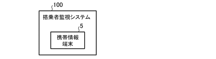
- It is a block diagram which shows the system configuration of the passenger monitoring system which concerns on Embodiment 1.
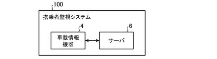
- FIG. It is a block diagram which shows the other system configuration of the passenger monitoring system which concerns on Embodiment 1.
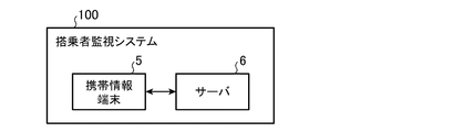
- FIG. It is a block diagram which shows the other system configuration of the passenger monitoring system which concerns on Embodiment 1.
- FIG. It is a block diagram which shows the other system configuration of the passenger monitoring system which concerns on Embodiment 1.
- FIG. It is a block diagram which shows the other system configuration of the passenger monitoring system which concerns on Embodiment 1.
- FIG. It is a block diagram which shows the other system configuration of the passenger monitoring system which concerns on Embodiment 1.
- FIG. It is a block diagram which shows the other system configuration of the passenger monitoring system which concerns on Embodiment 1.
- FIG. 1 It is a block diagram which shows the other system configuration of the passenger monitoring system which concerns on Embodiment 1.
- FIG. It is a block diagram which shows the other system configuration of the passenger monitoring system which concerns on Embodiment 1.
- FIG. It is a block diagram which shows the other system configuration of the passenger monitoring system which concerns on Embodiment 1.
- FIG. It is a block diagram which shows the main part of the passenger monitoring system which concerns on Embodiment 2.
- FIG. It is a block diagram which shows the main part of the pupil detection apparatus in the passenger monitoring system which concerns on Embodiment 2.
- FIG. It is explanatory drawing which shows the example of a plurality of directions. It is a flowchart which shows the operation of the pupil detection apparatus in the passenger monitoring system which concerns on Embodiment 2.
- FIG. 2 It is a block diagram which shows the other system configuration of the passenger monitoring system which concerns on Embodiment 1.
- FIG. It is a block diagram which shows the other system configuration of the passenger monitoring system which concerns on Embod
- FIG. 1 It is a block diagram which shows the main part of the passenger monitoring system which concerns on Embodiment 3. It is a block diagram which shows the main part of the pupil detection device in the passenger monitoring system which concerns on Embodiment 3.
- FIG. It is a flowchart which shows the operation of the pupil detection apparatus in the passenger monitoring system which concerns on Embodiment 3.
- FIG. 1 is a block diagram showing a main part of the passenger monitoring system according to the first embodiment.
- FIG. 2 is a block diagram showing a main part of the pupil detection device in the passenger monitoring system according to the first embodiment.
- the passenger monitoring system according to the first embodiment will be described with reference to FIGS. 1 and 2.
- the vehicle 1 is provided with a camera 2 and an output device 3.
- the camera 2 is composed of a camera for imaging the interior of the vehicle. That is, the camera 2 is provided in the front portion of the vehicle interior of the vehicle 1. Specifically, for example, the camera 2 is provided at a position near the center console on the dashboard of the vehicle 1 or at a position near the steering column on the dashboard of the vehicle 1.
- the range imaged by the camera 2 includes the driver's seat of the vehicle 1. As a result, when the driver is seated in the driver's seat of the vehicle 1, an image including the driver's face is captured.
- the imaging range may include the passenger seat of the vehicle 1. As a result, when the passenger is seated in the passenger seat of the vehicle 1, an image including the face of the passenger is captured.
- the passenger to be imaged by the camera 2 may be referred to as the "image target person". That is, the person to be imaged indicates the driver of the vehicle 1.
- the image pickup target indicates each of the driver of the vehicle 1 and the passengers of the vehicle 1.
- the output device 3 includes at least one of a display, a speaker, and a wireless communication device.
- the display is composed of, for example, a liquid crystal display, an organic EL (Electroluminescence) display, or a head-up display.
- the display is provided, for example, on the dashboard of vehicle 1.
- the speaker is provided on the dashboard of the vehicle 1, for example.
- the wireless communication device is composed of a transmitter and a receiver.
- the passenger monitoring system 100 includes a camera 2, an output device 3, and a passenger monitoring device 200.
- the passenger monitoring device 200 includes a captured image acquisition unit 11, a face feature point extraction unit 12, a face orientation estimation unit 13, a occupant state determination unit 14, a warning output control unit 15, and a line-of-sight detection device 300.
- the line-of-sight detection device 300 includes a line-of-sight angle calculation unit 21, a line-of-sight direction detection unit 22, and a pupil detection device 400.
- the pupil detection device 400 includes an eye region image acquisition unit 31, a luminance gradient calculation unit 32, an evaluation value calculation unit 33, and a pupil position detection unit 34.
- the evaluation value calculation unit 33 has a first evaluation value calculation unit 41.
- the captured image acquisition unit 11 acquires image data (hereinafter referred to as "first image data") indicating the image I1 captured by the camera 2.
- the captured image acquisition unit 11 outputs the acquired first image data to the face feature point extraction unit 12 and the eye region image acquisition unit 31.
- the face feature point extraction unit 12 acquires the first image data output by the captured image acquisition unit 11.
- the face feature point extraction unit 12 extracts a plurality of face feature points in the captured image I1 using the acquired first image data.
- the face feature point extraction unit 12 outputs information indicating the extracted plurality of face feature points (hereinafter referred to as “face feature point information”) to the face orientation estimation unit 13.
- face feature point information information indicating the extracted plurality of face feature points
- either one of the left eye of the image subject and the right eye of the image subject is referred to as a "line-of-sight detection target eye”.
- each of the left eye of the image subject and the right eye of the image subject is referred to as a "line-of-sight detection target eye”.
- the plurality of facial feature points extracted by the face feature point extraction unit 12 correspond to the feature points corresponding to the outer corners of the eyes to be detected by the line of sight (hereinafter referred to as "first feature points”) FP1 and the inner corners of the eyes to be detected by the line of sight.
- Feature points (hereinafter referred to as “second feature points”) FP2
- feature points corresponding to the upper eyelid of the eye to be detected (hereinafter referred to as "third feature point”) FP3
- the lower eyelid of the eye to be detected includes the corresponding feature point (hereinafter referred to as "fourth feature point”) FP4.
- the face feature point extraction unit 12 provides information indicating the extracted first feature point FP1, second feature point FP2, third feature point FP3, and fourth feature point FP4 (hereinafter referred to as "eye feature point information"). It is output to the line-of-sight angle calculation unit 21 and the eye region image acquisition unit 31.
- the face orientation estimation unit 13 acquires the face feature point information output by the face feature point extraction unit 12.
- the face orientation estimation unit 13 estimates the face orientation of the person to be imaged by using the acquired face feature point information.
- the face orientation estimation unit 13 outputs information indicating the estimated face orientation (hereinafter referred to as “face orientation information”) to the occupant state determination unit 14 and the line-of-sight direction detection unit 22.
- the face orientation estimation unit 13 calculates a vector (hereinafter referred to as “face orientation vector”) V1 indicating the face orientation of the imaging target person using the acquired face feature point information.
- the face orientation information includes the calculated face orientation vector V1.
- Various known techniques can be used to calculate the face orientation vector V1. Detailed description of these techniques will be omitted.
- the eye area image acquisition unit 31 acquires the eye feature point information output by the face feature point extraction unit 12.
- the eye region image acquisition unit 31 uses the acquired eye feature point information to detect a region (hereinafter, referred to as “eye region”) including the line-of-sight detection target eye in the captured image I1.
- eye region a region including the line-of-sight detection target eye in the captured image I1.
- Various known techniques can be used to detect the ocular region. Detailed description of these techniques will be omitted.
- the eye region image acquisition unit 31 acquires the first image data output by the captured image acquisition unit 11.
- the eye region image acquisition unit 31 uses the acquired first image data to show image data (hereinafter, “eye region image”) I2 corresponding to the eye region of the captured image I1 (hereinafter, “eye region image”). It is called "second image data").
- the eye region image acquisition unit 31 outputs the acquired second image data to the luminance gradient calculation unit 32.
- FIG. 3 shows an example of the eye region image I2.
- the eye region image I2 is composed of a plurality of units (hereinafter referred to as “image units”) U arranged in two directions (that is, the X direction and the Y direction) orthogonal to each other.
- each image unit U is composed of one pixel.
- each image unit U is composed of a plurality of pixels adjacent to each other.
- the brightness gradient calculation unit 32 acquires the second image data output by the eye region image acquisition unit 31.
- the luminance gradient calculation unit 32 calculates the luminance gradient vector V2 corresponding to each image unit U in the eye region image I2 by using the acquired second image data.
- the luminance gradient calculation unit 32 outputs information indicating the calculated luminance gradient vector V2 (hereinafter referred to as “luminance gradient information”) to the evaluation value calculation unit 33.
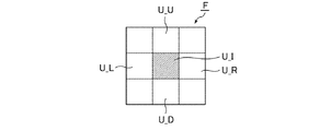
- the filter F shown in FIG. 4 is used for calculating the luminance gradient vector V2.
- the filter F is applied so as to sweep the eye region image I2 as shown in FIG.
- the filter F has a brightness value B_L and a attention image in the image unit U_L arranged to the left of the attention image unit U_I for each image unit (hereinafter, may be referred to as "attention image unit”) U_I in the eye region image I2.
- the difference value (hereinafter referred to as “first brightness gradient value”) ⁇ B_X from the brightness value B_R in the image unit U_R arranged to the right of the unit U_I is calculated.
- the filter F is a difference value between the luminance value B_U in the image unit U_U arranged above the attention image unit U_I and the luminance value B_D in the image unit U_D arranged below the attention image unit U_I (hereinafter, "second”. It is called "luminance gradient value”.) ⁇ B_Y is calculated.
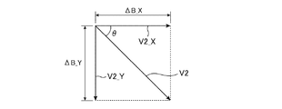
- the luminance gradient vector V2 is represented by the sum of the vector V2_X corresponding to the first luminance gradient value ⁇ B_X and the vector V2_Y corresponding to the second luminance gradient value ⁇ B_Y. Therefore, the filter F uses the calculated first luminance gradient value ⁇ B_X and the calculated second luminance gradient value ⁇ B_Y to indicate an angle corresponding to the direction of the luminance gradient vector V2 (hereinafter referred to as “luminance gradient angle”). ) Calculate ⁇ .
- the luminance gradient information includes the calculated luminance gradient angle ⁇ .
- the luminance value B_L is 44
- the luminance value B_R is 16
- the luminance value B_U is 47
- the luminance value B_D is 18.
- the filter F by applying the filter F to the image unit U_I of interest, the first luminance gradient value ⁇ B_X is calculated to ⁇ 28 and the second luminance gradient value ⁇ B_Y is calculated to ⁇ 29. Further, the luminance gradient angle ⁇ is calculated to be 46 °.
- FIG. 8 shows an example of the luminance gradient vector V2 based on these values.
- the evaluation value calculation unit 33 acquires the brightness gradient information output by the brightness gradient calculation unit 32.
- the evaluation value calculation unit 33 calculates the evaluation value E corresponding to each image unit U in the eye region image I2 by using the acquired luminance gradient information.
- the evaluation value calculation unit 33 outputs information including the calculated evaluation value E (hereinafter referred to as “evaluation value information”) to the pupil position detection unit 34.
- the evaluation value E calculated by the evaluation value calculation unit 33 includes the first evaluation value E1 calculated by the first evaluation value calculation unit 41. That is, the evaluation value information includes the calculated first evaluation value E1.
- the first evaluation value E1 is based on the number n of the luminance gradient vectors V2 toward the individual image unit U (that is, the attention image unit U_I). A method of calculating the first evaluation value E1 will be described with reference to FIGS. 9 and 10.
- the first evaluation value calculation unit 41 sets an evaluation area (hereinafter referred to as "evaluation area") EA including the image unit U_I of interest.
- the evaluation region EA includes the attention image unit U_I, and includes N image units (hereinafter, may be referred to as “evaluation image unit”) U_E different from the attention image unit U_I.
- N is any integer greater than or equal to 2.
- FIG. 9 shows an example of the evaluation area EA.
- the shape of the evaluation region EA is square, and the image unit U_I of interest is arranged at the center of the evaluation region EA.
- the evaluation area EA has a size smaller than a predetermined size (hereinafter referred to as "reference iris size").
- the reference iris size corresponds to the size of a standard human iris.
- the first evaluation value calculation unit 41 calculates the angle ⁇ 'corresponding to the inclination of the straight line connecting the attention image unit U_I and the individual evaluation image units U_E.
- the first evaluation value calculation unit 41 calculates the difference value ⁇ between the corresponding luminance gradient angle ⁇ and the corresponding angle ⁇ 'for each evaluation image unit U_E.
- the first evaluation value calculation unit 41 determines that the corresponding luminance gradient vector V2 has a direction toward the attention image unit U_I.
- the first evaluation value calculation unit 41 determines that the corresponding luminance gradient vector V2 does not have a direction toward the attention image unit U_I.
- the first evaluation value calculation unit 41 calculates the number n of the luminance gradient vectors V2 toward the attention image unit U_I based on the result of such determination.
- the number n is calculated as a value of 0 or more and N or less.
- the evaluation value calculation unit 33 calculates the first evaluation value E1 according to the calculated number n. That is, the larger the number n, the higher the first evaluation value E1 is calculated. In other words, the smaller the number n, the lower the first evaluation value E1 is calculated.
- the solid line arrow indicates the luminance gradient vector V2 having a direction toward the image unit U_I of interest.
- the arrow indicated by the broken line indicates the luminance gradient vector V2 having no direction toward the image unit U_I of interest.
- the number n is calculated to 19 by the first evaluation value calculation unit 41. Further, the first evaluation value calculation unit 41 calculates the first evaluation value E1 according to the calculated number n. For example, the first evaluation value E1 based on n / N is calculated.
- the pupil position detection unit 34 acquires the evaluation value information output by the evaluation value calculation unit 33.
- the pupil position detection unit 34 detects the pupil position PP in the eye region image I2 by using the acquired evaluation value information.
- the pupil position detection unit 34 outputs information indicating the detected pupil position PP (hereinafter referred to as “pupil position information”) to the line-of-sight angle calculation unit 21.
- the pupil position detection unit 34 detects the coordinate values C_X and C_Y indicating the position of the image unit U corresponding to the pupil position PP in the eye region image I2 by using the acquired evaluation value information. ..
- the pupil position information includes the detected coordinate values C_X and C_Y.
- the pupil position detection unit 34 detects the maximum value among the plurality of first evaluation values E1 corresponding to the plurality of image units U in the eye region image I2. In other words, the pupil position detecting unit 34 detects the maximum value in the plurality of first evaluation values E1.
- the pupil position detection unit 34 detects the coordinate values C_X and C_Y indicating the position of the image unit U corresponding to the detected maximum value. As a result, the coordinate values C_X and C_Y corresponding to the pupil position PP are detected.
- the ocular region image I2 is usually composed of a region corresponding to the inside of the ocular fissure (hereinafter referred to as “intraocular fissure region”) and a region corresponding to the outside of the ocular fissure (hereinafter referred to as “extraocular fissure region”). It is configured.
- the extraocular region is located around the intraocular region.
- the intraocular fissure region includes a region corresponding to the pupil (hereinafter referred to as “pupil region”), a region corresponding to the iris (hereinafter referred to as “iris region”), and a region corresponding to the sclera (hereinafter referred to as “sclera region”). ".) Is included.
- the scleral region is located around the iris region.
- the iris region is located around the pupil region.
- the shape of the iris region is circular.
- the shape of the pupil region is circular.
- the brightness in the pupil region is usually lower than the brightness in the iris region. Therefore, in the intraocular fissure region, an edge based on the brightness discontinuity is generated at the boundary between the pupil region and the iris region. Moreover, the brightness in the iris region is lower than the brightness in the sclera region. Therefore, in the intraocular fissure region, an edge based on the brightness discontinuity is generated at the boundary between the iris region and the scleral region.
- the pupil position PP can be detected by detecting the maximum value of the first evaluation value E1 (that is, the maximum value in the first evaluation value E1).
- the line-of-sight angle calculation unit 21 acquires the eye feature point information output by the face feature point extraction unit 12 and the pupil position information output by the pupil position detection unit 34.
- the line-of-sight angle calculation unit 21 calculates the line-of-sight angle ⁇ of the person to be imaged by using the acquired eye feature point information and the acquired pupil position information.
- the line-of-sight angle calculation unit 21 outputs information including the calculated line-of-sight angle ⁇ (hereinafter referred to as “line-of-sight angle information”) to the line-of-sight direction detection unit 22.
- the line-of-sight angle ⁇ includes the line-of-sight angle ⁇ _X with respect to the yaw direction and the line-of-sight angle ⁇ _Y with respect to the pitch direction.
- a method of calculating the line-of-sight angle ⁇ _X will be described with reference to FIG.
- a method of calculating the line-of-sight angle ⁇ _Y will be described with reference to FIG.
- the line-of-sight angle calculation unit 21 calculates the positions P_FP1_X and P_FP2_X in the X direction using the acquired eye feature point information.
- the position P_FP1_X corresponds to the first feature point FP1 (that is, the outer corner of the eye).
- the position P_FP2_X corresponds to the second feature point FP2 (that is, the inner corner of the eye).
- the line-of-sight angle calculation unit 21 calculates the position (hereinafter referred to as "first reference position") P_C_X in the X direction based on the calculated positions P_FP1_X and P_FP2_X.
- the first reference position P_C_X corresponds to an intermediate position between the first feature point FP1 and the second feature point FP2. That is, the first reference position P_C_X corresponds to the central portion of the intraocular fissure region with respect to the X direction.
- the line-of-sight angle calculation unit 21 calculates the position P_PP_X with respect to the X direction using the acquired pupil position information.
- the position P_PP_X corresponds to the pupil position PP.
- the line-of-sight angle calculation unit 21 calculates the interval L_X_1 with respect to the first reference position P_C_X and the interval L_X_2 with respect to the position P_PP_X for the position P_FP1_X or the position P_FP2_X.
- FIG. 11 shows an example when the position P_FP2_X is used as a reference for the intervals L_X_1 and L_X_2.
- the line-of-sight angle calculation unit 21 is preset with a value indicating the maximum value ⁇ max_X of the line-of-sight angle ⁇ _X.
- the line-of-sight angle calculation unit 21 calculates the line-of-sight angle ⁇ _X by the following equation (1) using the set maximum value ⁇ max_X and the calculated intervals L_X_1 and L_X_2.
- ⁇ _X ⁇ max_X ⁇ (L_X_1-L_X_2) / L_X_1 (1)
- the maximum value ⁇ max_X is based on, for example, the following model M_X. That is, in the model M_X, if the position P_PP_X is the same as the first reference position P_C_X, the line-of-sight angle ⁇ _X is 0 °. Further, in the model M_X, if the position P_PP_X is the same as the position P_FP1_X, the line-of-sight angle ⁇ _X becomes a value (for example, ⁇ 60 °) corresponding to the maximum value ⁇ max_X.
- the line-of-sight angle ⁇ _X becomes a value (for example, + 60 °) corresponding to the maximum value ⁇ max_X.
- the line-of-sight angle calculation unit 21 calculates the positions P_FP3_Y and P_FP4_Y in the Y direction by using the acquired eye feature point information.
- the position P_FP3_X corresponds to the third feature point FP3 (ie, upper eyelid).
- the position P_FP4_Y corresponds to the fourth feature point FP4 (ie, lower eyelid).
- the line-of-sight angle calculation unit 21 calculates the position in the Y direction (hereinafter referred to as “second reference position”) P_C_Y based on the calculated positions P_FP3_Y and P_FP4_Y.
- the second reference position P_C_Y corresponds to an intermediate position between the third feature point FP3 and the fourth feature point FP4. That is, the second reference position P_C_Y corresponds to the central portion of the intraocular fissure region with respect to the Y direction.
- the line-of-sight angle calculation unit 21 calculates the position P_PP_Y with respect to the Y direction using the acquired pupil position information.
- the position P_PP_Y corresponds to the pupil position PP.
- the line-of-sight angle calculation unit 21 calculates the interval L_Y_1 with respect to the second reference position P_C_Y and the interval L_Y_2 with respect to the position P_PP_Y for the position P_FP3_Y or the position P_FP4_Y.
- FIG. 12 shows an example when the position P_FP3_Y is used as a reference for the intervals L_Y_1 and L_Y_2.
- the line-of-sight angle calculation unit 21 is preset with a value indicating the maximum value ⁇ max_Y of the line-of-sight angle ⁇ _Y.
- the line-of-sight angle calculation unit 21 calculates the line-of-sight angle ⁇ _Y by the following equation (2) using the set maximum value ⁇ max_Y and the calculated intervals L_X_1 and L_X_2.
- ⁇ _Y ⁇ max_Y ⁇ (L_Y_1-L_Y_2) / L_Y_1 (2)
- the maximum value ⁇ max_Y is based on, for example, the following model M_Y. That is, in the model M_Y, if the position P_PP_Y is the same as the second reference position P_C_Y, the line-of-sight angle ⁇ _Y is 0 °. Further, in the model M_Y, if the position P_PP_Y is the same as the position P_FP3_Y, the line-of-sight angle ⁇ _Y becomes a value (for example, + 20 °) corresponding to the maximum value ⁇ max_Y.
- the line-of-sight angle ⁇ _Y becomes a value (for example, ⁇ 20 °) corresponding to the maximum value ⁇ max_Y.
- the method of calculating the line-of-sight angles ⁇ _X and ⁇ _Y is not limited to these specific examples.
- Various known techniques can be used to calculate the line-of-sight angles ⁇ _X and ⁇ _Y. Detailed description of these techniques will be omitted.
- the line-of-sight direction detection unit 22 acquires the face direction information output by the face direction estimation unit 13 and the line-of-sight angle information output by the line-of-sight angle calculation unit 21.
- the line-of-sight direction detection unit 22 detects the line-of-sight direction of the person to be imaged by using the acquired face orientation information and the acquired line-of-sight angle information.
- the line-of-sight direction detection unit 22 outputs information indicating the detected line-of-sight direction (hereinafter referred to as “line-of-sight direction information”) to the occupant state determination unit 14.
- the line-of-sight direction detection unit 22 uses the face-direction vector V1 calculated by the face-direction estimation unit 13 and the line-of-sight angle ⁇ calculated by the line-of-sight angle calculation unit 21 to determine the line-of-sight direction of the person to be imaged.
- the indicated vector hereinafter referred to as “line-of-sight direction vector” V3 is calculated.
- the line-of-sight direction information includes the calculated line-of-sight direction vector V3.
- Various known techniques can be used to calculate the line-of-sight direction vector V3. Detailed description of these techniques will be omitted.
- the passenger state determination unit 14 acquires the face orientation information output by the face orientation estimation unit 13 and the line-of-sight direction information output by the line-of-sight direction detection unit 22.
- the passenger state determination unit 14 uses at least one of the acquired face orientation information and the acquired line-of-sight direction information to determine the state of the person to be imaged to be a predetermined state (hereinafter referred to as “warning target state”. ) Is determined.
- the passenger status determination unit 14 outputs information indicating the result of such determination (hereinafter referred to as “determination result information”) to the warning output control unit 15.
- the warning target state includes a state in which the driver of the vehicle 1 is inattentive driving (hereinafter referred to as "inattentive driving state"). Whether or not the driver's state is the inattentive driving state is determined as follows, for example.
- the passenger status determination unit 14 acquires information indicating the traveling direction of the vehicle 1. Such information is obtained, for example, from a navigation system in vehicle 1 or a sensor in vehicle 1.
- the occupant state determination unit 14 uses the acquired information to calculate a vector V3'corresponding to the line-of-sight direction vector V3 when the driver's line of sight is directed to the traveling direction of the vehicle 1.
- the occupant state determination unit 14 compares the calculated vector V3'with the line-of-sight direction vector V3 indicated by the acquired line-of-sight direction information to determine whether or not the driver's state is an inattentive driving state. judge.
- the warning target state includes a state in which the driver of the vehicle 1 does not check the rear at the timing when the driver should check the rear (hereinafter referred to as "rear careless state"). Whether or not the driver's state is inattentive to the rear is determined, for example, as follows.
- the occupant state determination unit 14 acquires information indicating the installation position of the rear-view mirror (for example, a room mirror or a side mirror) in the vehicle 1.
- the occupant state determination unit 14 uses the acquired information to calculate a vector V3 ”corresponding to the line-of-sight direction vector V3 when the driver's line of sight is directed to the rear-viewing mirror.
- the occupant state determination unit 14 acquires information indicating the timing when the driver of the vehicle 1 should check the rear (for example, the timing when the vehicle 1 makes a right turn, a left turn, or a lane change). The occupant state determination unit 14 compares the calculated vector V3 "with the line-of-sight direction vector V3 indicated by the acquired line-of-sight direction information at the timing indicated by the acquired information. Determine if the state is a backward careless state.
- the warning target state includes a state in which the driver's attention of the vehicle 1 is reduced (hereinafter referred to as "attention reduced state").
- attention reduced state a state in which the driver's attention of the vehicle 1 is reduced.
- a determination result relating to an inattentive driving state over a predetermined time or a determination result relating to a backward careless state over a predetermined time is used.
- the warning target state includes a state in which the driver of the vehicle 1 is dozing off (hereinafter referred to as "sleeping driving state").
- the acquired face orientation information is used to determine whether or not the driver's state is a dozing driving state.
- the warning target state includes a state in which the driver of the vehicle 1 cannot drive (hereinafter referred to as a "deadman state").
- the acquired face orientation information is used to determine whether or not the driver's state is a deadman state.
- the warning output control unit 15 acquires the determination result information output by the passenger status determination unit 14. The warning output control unit 15 determines the necessity of outputting a warning by using the acquired determination result information. The warning output control unit 15 executes control to output a warning by using the output device 3 when it is determined that the output of the warning is necessary.
- the warning output control unit 15 determines whether or not a warning image (hereinafter referred to as “warning image”) needs to be displayed by using the acquired determination result information. When it is determined that the warning image needs to be displayed, the warning output control unit 15 executes control to display the warning image using the display included in the output device 3.
- warning image a warning image
- the warning output control unit 15 executes control to display the warning image using the display included in the output device 3.
- the warning output control unit 15 determines the necessity of outputting a warning voice (hereinafter referred to as "warning voice") by using the acquired determination result information. When it is determined that the output of the warning voice is necessary, the warning output control unit 15 executes control to output the warning voice using the speaker included in the output device 3.
- warning voice a warning voice
- the warning output control unit 15 executes control to output the warning voice using the speaker included in the output device 3.
- the warning output control unit 15 determines whether or not a warning signal (hereinafter referred to as “warning signal”) needs to be transmitted by using the acquired determination result information. When it is determined that the warning signal needs to be transmitted, the warning output control unit 15 executes control for transmitting the warning signal using the wireless communication device included in the output device 3.
- warning signal a warning signal
- the warning output control unit 15 executes control for transmitting the warning signal using the wireless communication device included in the output device 3.
- the reference numeral "F1" may be used for the function of the captured image acquisition unit 11.
- the reference numeral “F2” may be used for the function of the face feature point extraction unit 12.
- the reference numeral “F3” may be used for the function of the face orientation estimation unit 13.
- the code of "F4" may be used for the function of the passenger state determination unit 14.
- the reference numeral "F5" may be used for the function of the warning output control unit 15.
- the code of "F11” may be used for the function of the line-of-sight angle calculation unit 21. Further, the reference numeral “F12” may be used for the function of the line-of-sight direction detection unit 22.
- the reference numeral “F21” may be used for the function of the eye region image acquisition unit 31. Further, the reference numeral of the function "F22" of the luminance gradient calculation unit 32 may be used. Further, the reference numeral of "F23” may be used for the function of the evaluation value calculation unit 33. In addition, the reference numeral “F24” may be used for the function of the pupil position detection unit 34.
- the processes executed by the eye region image acquisition unit 31 may be collectively referred to as "eye region image acquisition processing”.
- the processes executed by the luminance gradient calculation unit 32 may be collectively referred to as “luminance gradient calculation process”.
- the processes executed by the evaluation value calculation unit 33 may be collectively referred to as “evaluation value calculation process”.
- the processes executed by the pupil position detection unit 34 may be collectively referred to as “pupil position detection process”.
- the processes executed by the pupil detection device 400 may be collectively referred to as "pupil detection process”. That is, the pupil detection process includes an eye region image acquisition process, a luminance gradient calculation process, an evaluation value calculation process, and a pupil position detection process.
- the processes executed by the line-of-sight angle calculation unit 21 may be collectively referred to as “line-of-sight angle calculation process”.
- the processes executed by the line-of-sight direction detection unit 22 may be collectively referred to as “line-of-sight direction detection process”.
- the processes executed by the line-of-sight detection device 300 may be collectively referred to as "line-of-sight detection process”. That is, the line-of-sight detection process includes a pupil detection process, a line-of-sight angle calculation process, and a line-of-sight direction detection process.
- the processes executed by the captured image acquisition unit 11 may be collectively referred to as “captured image acquisition process”.
- the processes executed by the face feature point extraction unit 12 may be collectively referred to as “face feature point extraction process”.
- the processes executed by the face orientation estimation unit 13 may be collectively referred to as “face orientation estimation processing”.
- the processes executed by the passenger status determination unit 14 may be collectively referred to as “passenger status determination processing”.
- the processing and control executed by the warning output control unit 15 may be collectively referred to as "warning output control”.
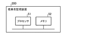
- the passenger monitoring device 200 has a processor 51 and a memory 52.
- the memory 52 stores programs corresponding to a plurality of functions F1 to F5, F11, F12, and F21 to F24.
- the processor 51 reads and executes the program stored in the memory 52. As a result, a plurality of functions F1 to F5, F11, F12, and F21 to F24 are realized.
- the passenger monitoring device 200 has a processing circuit 53.
- the processing circuit 53 executes processing corresponding to a plurality of functions F1 to F5, F11, F12, and F21 to F24. As a result, a plurality of functions F1 to F5, F11, F12, and F21 to F24 are realized.
- the passenger monitoring device 200 includes a processor 51, a memory 52, and a processing circuit 53.
- the memory 52 stores programs corresponding to some of the plurality of functions F1 to F5, F11, F12, and F21 to F24.
- the processor 51 reads and executes the program stored in the memory 52. As a result, some of these functions are realized.
- the processing circuit 53 executes processing corresponding to the remaining functions of the plurality of functions F1 to F5, F11, F12, and F21 to F24. As a result, such a residual function is realized.
- the processor 51 is composed of one or more processors.
- processors for example, a CPU (Central Processing Unit), a GPU (Graphics Processing Unit), a microprocessor, a microcontroller, or a DSP (Digital Signal Processor) is used.
- CPU Central Processing Unit
- GPU Graphics Processing Unit
- DSP Digital Signal Processor
- the memory 52 is composed of one or more non-volatile memories.
- the memory 52 is composed of one or more non-volatile memories and one or more volatile memories. That is, the memory 52 is composed of one or more memories.
- Each memory uses, for example, a semiconductor memory or a magnetic disk.
- each volatile memory uses, for example, a RAM (Random Access Memory).
- the individual non-volatile memory is, for example, a ROM (Read Only Memory), a flash memory, an EPROM (Erasable Programmable Read Only Memory), an EEPROM (Electrically Erasable Programmory), an EEPROM (Electrically Erasable Programmory) drive, or a hard disk drive that uses a hard disk drive, a hard disk, or a drive solid state drive. Is.
- the processing circuit 53 is composed of one or more digital circuits.
- the processing circuit 53 is composed of one or more digital circuits and one or more analog circuits. That is, the processing circuit 53 is composed of one or more processing circuits.
- the individual processing circuits are, for example, ASIC (Application Special Integrated Circuit), PLD (Programmable Logic Device), FPGA (Field Programmable Gate Array), FPGA (Field Program Is.
- the processor 51 is composed of a plurality of processors
- the correspondence between the plurality of functions F1 to F5, F11, F12, F21 to F24 and the plurality of processors is arbitrary. That is, each of the plurality of processors may read and execute a program corresponding to one or more corresponding functions among the plurality of functions F1 to F5, F11, F12, and F21 to F24. ..
- each of the plurality of memories may store a program corresponding to one or more corresponding functions among the plurality of functions F1 to F5, F11, F12, and F21 to F24.
- each of the plurality of processing circuits may execute processing corresponding to one or more corresponding functions among the plurality of functions F1 to F5, F11, F12, and F21 to F24.
- the process shown in FIG. 16 is repeatedly executed when a predetermined condition is satisfied (for example, when the ignition power supply in the vehicle 1 is turned on).
- the captured image acquisition unit 11 executes the captured image acquisition process (step ST1).
- the face feature point extraction unit 12 executes the face feature point extraction process (step ST2).
- the face orientation estimation unit 13 executes the face orientation estimation process (step ST3).
- the line-of-sight detection device 300 executes the line-of-sight detection process (step ST4).
- the passenger status determination unit 14 executes the passenger status determination process (step ST5).
- the warning output control unit 15 executes the warning output control (step ST6).
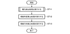
- step ST4 shown in FIG. 16 will be described.
- the pupil detection device 400 executes the pupil detection process (step ST11).
- the line-of-sight angle calculation unit 21 executes the line-of-sight angle calculation process (step ST12).
- the line-of-sight direction detection unit 22 executes the line-of-sight direction detection process (step ST13).
- step ST11 shown in FIG. 17 will be described.
- the eye region image acquisition unit 31 executes the eye region image acquisition process (step ST21).
- the luminance gradient calculation unit 32 executes the luminance gradient calculation process (step ST22).
- the evaluation value calculation unit 33 executes the evaluation value calculation process (step ST23).
- the pupil position detection unit 34 executes the pupil position detection process (step ST24).
- the conventional pupil detection device detects the corneal reflex image in the captured image and detects the pupil position using the detected corneal reflex image. Therefore, there is a problem that the pupil position cannot be detected when the corneal reflex image is not detected normally.
- the pupil detection device 400 it is not necessary to detect the corneal reflex image when detecting the pupil position PP. Therefore, the pupil position PP can be detected regardless of whether or not the corneal reflex image is normally detected. As a result, even when the pupil detection device 400 is used in the passenger monitoring system 100, the pupil position PP can be stably detected.
- the pupil detection device 400 uses the evaluation value E based on the luminance gradient vector V2 when detecting the pupil position PP.
- the pupil position PP can be detected with high accuracy.
- the pupil position PP can be detected regardless of the size of the pupil in the eye to be detected by the line of sight (that is, regardless of the size of the pupil region in the eye region image I2).
- the evaluation area EA has a size smaller than the reference iris size.
- the evaluation value calculation process can be speeded up.
- a high evaluation value E can be calculated for the image unit U in the pupil region by the edge based on the discontinuity of brightness at the boundary portion between the pupil region and the iris region.
- the portion corresponding to the outer corner of the eye in the eye region image I2 is referred to as the "outer corner of the eye”. Further, the portion corresponding to the inner corner of the eye in the eye region image I2 is referred to as “the inner corner of the eye”. Further, the portion corresponding to the upper eyelid in the eye region image I2 is referred to as an "upper eyelid portion”. Further, the portion corresponding to the lower eyelid in the eye region image I2 is referred to as a "lower eyelid portion”.
- the area corresponding to the left half of the evaluation area EA when the line-of-sight detection target eye is the left eye or the area corresponding to the right half of the evaluation area EA when the line-of-sight detection target eye is the right eye is referred to as "the th. It is called “1 partial evaluation area”. Further, the area corresponding to the right half of the evaluation area EA when the line-of-sight detection target eye is the left eye or the area corresponding to the left half of the evaluation area EA when the line-of-sight detection target eye is the right eye is defined as "the third. It is called "two partial evaluation areas”. The area corresponding to the lower half of the evaluation area EA is referred to as a "third part evaluation area”. The area corresponding to the upper half of the evaluation area EA is referred to as a "fourth partial evaluation area".
- the line-of-sight detection target eye is the left eye
- the attention image unit U_I in the evaluation value calculation process is located at the inner corner of the eye
- the substantially left half of the evaluation region EA is located at the extraocular fissure region.
- a condition can occur.
- the line-of-sight detection target eye is the right eye
- the image unit U_I of interest in the evaluation value calculation process is located at the outer corner of the eye
- the substantially right half of the evaluation region EA is located in the extraocular fissure region. Can occur.
- the image unit U_I of interest in the evaluation value calculation process when the image unit U_I of interest in the evaluation value calculation process is located in the upper eyelid portion, a state in which substantially the upper half portion of the evaluation region EA is located in the extraocular fissure region may occur. Further, when the image unit U_I of interest in the evaluation value calculation process is located in the lower eyelid portion, a state in which substantially the lower half portion of the evaluation region EA is located in the extraocular fissure region may occur.
- the luminance gradient vector V2 corresponding to the image unit U in the extraocular fissure region may be used to calculate the first evaluation value E1.
- the detection accuracy of the pupil position PP may decrease.
- the first evaluation value calculation unit 41 may acquire the eye feature point information output by the face feature point extraction unit 12. The first evaluation value calculation unit 41 may determine whether or not the attention image unit U_I is located at the outer corner of the eye by using the acquired eye feature point information. The first evaluation value calculation unit 41 calculates the first evaluation value E1 by using the first partial evaluation area instead of the evaluation area EA when it is determined that the image unit U_I of interest is located at the outer corner of the eye. It may be.
- the first evaluation value calculation unit 41 may determine whether or not the attention image unit U_I is located at the inner corner of the eye by using the acquired eye feature point information. When it is determined that the image unit U_I of interest is located at the inner corner of the eye, the first evaluation value calculation unit 41 calculates the first evaluation value E1 using the second partial evaluation area instead of the evaluation area EA. It may be a thing.
- the first evaluation value calculation unit 41 may determine whether or not the attention image unit U_I is located in the upper eyelid portion by using the acquired eye feature point information. When it is determined that the image unit U_I of interest is located in the upper eyelid portion, the first evaluation value calculation unit 41 calculates the first evaluation value E1 using the third partial evaluation area instead of the evaluation area EA. It may be a thing.
- the first evaluation value calculation unit 41 may determine whether or not the attention image unit U_I is located in the lower eyelid portion by using the eye feature point information. When it is determined that the image unit U_I of interest is located in the lower eyelid portion, the first evaluation value calculation unit 41 calculates the first evaluation value E1 using the fourth partial evaluation area instead of the evaluation area EA. It may be a thing.
- the first evaluation value E1 is a value based on n / N. Instead of being calculated, it may be calculated based on n / (N / 2).
- the pupil position PP can be detected regardless of the position of the pupil in the eye to be detected (that is, regardless of the position of the pupil region in the eye region image I2).
- the pupil position PP can be detected even when the pupil is located in the vicinity of the upper eyelid.
- the luminance gradient calculation unit 32 calculates a value (hereinafter referred to as “luminance gradient value”) ⁇ B corresponding to the magnitude of the luminance gradient vector V2 by using the first luminance gradient value ⁇ B_X and the second luminance gradient value ⁇ B_Y. It may be.
- the luminance gradient information may include the calculated luminance gradient value ⁇ B.
- the first evaluation value calculation unit 41 may compare the brightness gradient value ⁇ B of the brightness gradient vector V2 corresponding to each evaluation image unit U_E with a predetermined threshold value ⁇ Bth. The first evaluation value calculation unit 41 may exclude the brightness gradient vector V2 having the brightness gradient value ⁇ B equal to or less than the threshold value ⁇ Bth from the calculation of the first evaluation value E1.
- the unnecessary luminance gradient vector V2 can be excluded from the calculation of the first evaluation value E1.
- the other luminance gradient vector V2 can be excluded from the calculation of the first evaluation value E1.
- the shape of the evaluation area EA is not limited to a square shape.
- the shape of the evaluation area EA may be any shape.
- the shape of the evaluation region EA may be an orthorhombic shape or a circular shape (see FIG. 19).
- the vehicle 1 may be equipped with the in-vehicle information device 4. Further, the mobile information terminal 5 may be brought into the vehicle 1. The in-vehicle information device 4 and the mobile information terminal 5 may be able to communicate with each other.
- the in-vehicle information device 4 may be capable of communicating with the server 6 outside the vehicle 1.
- the mobile information terminal 5 may be capable of communicating with the server 6 outside the vehicle 1.
- the camera 2 may be provided in the in-vehicle information device 4 or the mobile information terminal 5.
- the output device 3 may be provided in the in-vehicle information device 4 or the mobile information terminal 5.
- each of the plurality of functions F1 to F5, F11, F12, F21 to F24 may be realized by the in-vehicle information device 4, or may be realized by the portable information terminal 5.
- It may be realized by the server 6, or it may be realized by the cooperation of the in-vehicle information device 4 and the mobile information terminal 5, and the in-vehicle information device 4 and the server 6 cooperate with each other. It may be realized by doing so, or it may be realized by coordinating the mobile information terminal 5 and the server 6.
- the main part of the passenger monitoring system 100 may be configured by the in-vehicle information device 4.
- the main part of the passenger monitoring system 100 may be configured by the mobile information terminal 5.
- the main part of the passenger monitoring system 100 may be configured by the in-vehicle information device 4 and the mobile information terminal 5.
- the main part of the passenger monitoring system 100 may be configured by the in-vehicle information device 4 and the server 6.
- the main part of the passenger monitoring system 100 may be configured by the mobile information terminal 5 and the server 6.
- the main part of the passenger monitoring system 100 may be composed of the in-vehicle information device 4, the mobile information terminal 5, and the server 6.
- the pupil detection device 400 includes an eye region image acquisition unit 31 that acquires image data (second image data) indicating the eye region image I2 in the image captured by the camera 2, and an image.
- the brightness gradient calculation unit 32 that calculates the brightness gradient vector V2 corresponding to each image unit U in the eye region image I2 using the data (second image data), and the individual image unit U using the brightness gradient vector V2.
- It includes an evaluation value calculation unit 33 that calculates the corresponding evaluation value E, and a pupil position detection unit 34 that detects the pupil position PP in the eye region image I2 using the evaluation value E. This makes it unnecessary to detect the corneal reflex image when detecting the pupil position PP. As a result, the pupil position PP can be stably detected even when the camera 2 having a low resolution is used. In addition, the pupil position PP can be detected with high accuracy.
- the line-of-sight detection device 300 includes a pupil detection device 400, a line-of-sight angle calculation unit 21 that calculates a line-of-sight angle ⁇ based on the pupil position PP, and a line-of-sight direction that detects a line-of-sight direction based on the line-of-sight angle ⁇ .
- a detection unit 22 is provided. As a result, even when the camera 2 having a low resolution is used, the line-of-sight direction can be stably detected.
- the passenger monitoring system 100 is boarding that determines whether or not the state of the passenger (image target person) of the vehicle 1 is the warning target state based on the line-of-sight detection device 300 and the line-of-sight direction.
- a person status determination unit 14 and a warning output control unit 15 that executes control to output a warning according to a determination result by the passenger status determination unit 14 are provided. As a result, even when the camera 2 having a low resolution is used, the warning target state can be stably detected.
- the pupil detection method includes step ST21 in which the eye region image acquisition unit 31 acquires image data (second image data) indicating the eye region image I2 in the image captured by the camera 2, and brightness.
- Step ST22 in which the gradient calculation unit 32 calculates the brightness gradient vector V2 corresponding to each image unit U in the eye region image I2 using the image data (second image data), and the evaluation value calculation unit 33 perform the brightness gradient.
- Step ST23 for calculating the evaluation value E corresponding to each image unit U using the vector V2, and step ST24 for the pupil position detection unit 34 to detect the pupil position PP in the eye region image I2 using the evaluation value E. , Equipped with.
- the pupil position PP can be stably detected even when the camera 2 having a low resolution is used.
- the pupil position PP can be detected with high accuracy.
- FIG. 28 is a block diagram showing a main part of the passenger monitoring system according to the second embodiment.
- FIG. 29 is a block diagram showing a main part of the pupil detection device in the passenger monitoring system according to the second embodiment.
- the passenger monitoring system according to the second embodiment will be described with reference to FIGS. 28 and 29.
- the same blocks as those shown in FIG. 1 are designated by the same reference numerals, and the description thereof will be omitted.
- FIG. 29 the same blocks as those shown in FIG. 2 are designated by the same reference numerals, and the description thereof will be omitted.
- the passenger monitoring system 100a includes a camera 2, an output device 3, and a passenger monitoring device 200a.
- the passenger monitoring device 200a includes a captured image acquisition unit 11, a face feature point extraction unit 12, a face orientation estimation unit 13, a occupant state determination unit 14, a warning output control unit 15, and a line-of-sight detection device 300a.
- the line-of-sight detection device 300a includes a line-of-sight angle calculation unit 21, a line-of-sight direction detection unit 22, and a pupil detection device 400a.
- the pupil detection device 400a includes an eye region image acquisition unit 31, a luminance gradient calculation unit 32, an evaluation value calculation unit 33a, and a pupil position detection unit 34a.
- the evaluation value calculation unit 33a has a second evaluation value calculation unit 42.
- the evaluation value calculation unit 33a acquires the brightness gradient information output by the brightness gradient calculation unit 32.
- the evaluation value calculation unit 33a calculates the evaluation value E corresponding to each image unit U in the eye region image I2 by using the acquired luminance gradient information.
- the evaluation value calculation unit 33a outputs information including the calculated evaluation value E (that is, evaluation value information) to the pupil position detection unit 34a.
- the evaluation value E calculated by the evaluation value calculation unit 33a includes the second evaluation value E2 calculated by the second evaluation value calculation unit 42. That is, the evaluation value information includes the calculated second evaluation value E2.
- the second evaluation value E2 is based on the number of directions m of the luminance gradient vector V2 toward each image unit U (that is, the image unit of interest U_I). A method of calculating the second evaluation value E2 will be described with reference to FIG.
- the second evaluation value calculation unit 42 sets the evaluation area EA including the image unit U_I of interest.
- the evaluation area EA is the same as that described in the first embodiment. Therefore, the description will be omitted again.
- M directions D_1 to D_M toward the attention image unit U_I are set in advance.
- M is any integer greater than or equal to 2.
- the directions D_1 to D_8 are set in directions formed by dividing 360 ° into eight equal parts. That is, the directions D_1 to D_1 are set in the directions at intervals of 45 °.
- the acquired luminance gradient information includes the luminance gradient angles ⁇ corresponding to each direction of the N luminance gradient vectors V2 for the N luminance gradient vectors V2 corresponding to the N evaluation image units U_E. ing.
- the second evaluation value calculation unit 42 uses the brightness gradient vector V2 toward the image unit U_I of interest in each of the M directions D_1 to D_M in the direction corresponding to the direction D. Determine the presence or absence.
- the second evaluation value calculation unit 42 calculates the number of directions m of the luminance gradient vector V2 toward the image unit U_I of interest. That is, m is calculated as a value of 0 or more and M or less.
- the second evaluation value calculation unit 42 calculates the second evaluation value E2 according to the calculated number of directions m. That is, the larger the number of directions m, the higher the second evaluation value E2 is calculated. In other words, the smaller the number of directions m, the lower the second evaluation value E2 is calculated.
- the brightness gradient vectors V2 toward the attention image unit U_I in the directions corresponding to the directions D_1 and D_2 are included in the N brightness gradient vectors V2, and It is assumed that the brightness gradient vectors V2 toward the attention image unit U_I in the directions corresponding to the directions D_3 to D_8 are not included in the N brightness gradient vectors V2.
- the second evaluation value calculation unit 42 calculates the number of directions m to 2. Further, the second evaluation value calculation unit 42 calculates the second evaluation value E2 according to the calculated number of directions m. For example, the second evaluation value E2 based on m / M is calculated.
- the pupil position detection unit 34a acquires the evaluation value information output by the evaluation value calculation unit 33a.
- the pupil position detection unit 34a detects the pupil position PP in the eye region image I2 by using the acquired evaluation value information.
- the pupil position detection unit 34a outputs information indicating the detected pupil position PP (that is, pupil position information) to the line-of-sight angle calculation unit 21.
- the pupil position detection unit 34a detects the maximum value among the plurality of second evaluation values E2 corresponding to the plurality of image units U in the eye region image I2. In other words, the pupil position detecting unit 34a detects the maximum value in the plurality of second evaluation values E2.
- the pupil position detection unit 34a detects the coordinate values C_X and C_Y indicating the position of the image unit U corresponding to the detected maximum value. As a result, the coordinate values C_X and C_Y corresponding to the pupil position PP are detected.
- the principle that the pupil position PP is detected by detecting the maximum value (that is, the maximum value) is the same as that described in the first embodiment. Therefore, the description will be omitted again.
- the code of "F23a” may be used for the function of the evaluation value calculation unit 33a.
- the reference numeral “F24a” may be used for the function of the pupil position detection unit 34a.
- evaluation value calculation process the processes executed by the evaluation value calculation unit 33a may be collectively referred to as “evaluation value calculation process”. Further, the processes executed by the pupil position detection unit 34a may be collectively referred to as “pupil position calculation process”.
- the passenger monitoring device 200a has a plurality of functions F1 to F5, F11, F12, F21, F22, F23a, and F24a.
- Each of the plurality of functions F1 to F5, F11, F12, F21, F22, F23a, and F24a may be realized by the processor 51 and the memory 52, or may be realized by the processing circuit 53. You may.
- the operation of the passenger monitoring device 200a is the same as that described with reference to the flowchart of FIG. 16 in the first embodiment. Therefore, the description will be omitted again.
- the operation of the line-of-sight detection device 300a is the same as that described with reference to the flowchart of FIG. 17 in the first embodiment. Therefore, the description will be omitted again.
- FIG. 31 the same steps as those shown in FIG. 18 are designated by the same reference numerals and the description thereof will be omitted.
- step ST21 the processes of steps ST21 and ST22 are executed.
- the evaluation value calculation unit 33a executes the evaluation value calculation process (step ST23a).
- the pupil position detection unit 34a executes the pupil position detection process (step ST24a).
- the pupil detection device 400a can employ various modifications similar to those described in the first embodiment. Further, the passenger monitoring system 100a can adopt various modifications similar to those described in the first embodiment.
- the second evaluation value calculation unit 42 calculates the second evaluation value E2 using the first partial evaluation region when it is determined that the image unit U_I of interest is located at the outer corner of the eye. good. Further, the second evaluation value calculation unit 42 calculates the second evaluation value E2 using the second partial evaluation region when it is determined that the image unit U_I of interest is located at the inner corner of the eye. Is also good. Further, the second evaluation value calculation unit 42 calculates the second evaluation value E2 using the third partial evaluation region when it is determined that the image unit U_I of interest is located in the upper eyelid portion. Is also good. Further, the second evaluation value calculation unit 42 calculates the second evaluation value E2 using the fourth partial evaluation region when it is determined that the image unit U_I of interest is located in the lower eyelid portion. Is also good.
- the second evaluation value E2 is a value based on m / M. Instead of being calculated, it may be calculated based on m / (M / 2).
- the second evaluation value calculation unit 42 may exclude the brightness gradient vector V2 having the brightness gradient value ⁇ B equal to or less than the threshold value ⁇ Bth from the calculation of the second evaluation value E2.
- the evaluation value E includes the second evaluation value E2 based on the number of directions m of the luminance gradient vector V2 toward the individual image unit U.
- the first evaluation value E1 can be used, but also the second evaluation value E2 can be used.
- FIG. 32 is a block diagram showing a main part of the passenger monitoring system according to the third embodiment.
- FIG. 33 is a block diagram showing a main part of the pupil detection device in the passenger monitoring system according to the third embodiment.
- the passenger monitoring system according to the third embodiment will be described with reference to FIGS. 32 and 33.
- FIG. 32 the same blocks as those shown in FIG. 1 are designated by the same reference numerals, and the description thereof will be omitted.
- FIG. 33 the same blocks as those shown in FIG. 2 are designated by the same reference numerals, and the description thereof will be omitted.
- the passenger monitoring system 100b includes a camera 2, an output device 3, and a passenger monitoring device 200b.
- the passenger monitoring device 200b includes a captured image acquisition unit 11, a face feature point extraction unit 12, a face orientation estimation unit 13, a occupant state determination unit 14, a warning output control unit 15, and a line-of-sight detection device 300b.
- the line-of-sight detection device 300b includes a line-of-sight angle calculation unit 21, a line-of-sight direction detection unit 22, and a pupil detection device 400b.
- the pupil detection device 400b includes an eye region image acquisition unit 31, a luminance gradient calculation unit 32, an evaluation value calculation unit 33b, and a pupil position detection unit 34b.
- the evaluation value calculation unit 33b has a first evaluation value calculation unit 41 and a second evaluation value calculation unit 42.
- the evaluation value calculation unit 33b acquires the brightness gradient information output by the brightness gradient calculation unit 32.
- the evaluation value calculation unit 33b calculates the evaluation value E corresponding to each image unit U in the eye region image I2 by using the acquired luminance gradient information.
- the evaluation value calculation unit 33b outputs information including the calculated evaluation value E (that is, evaluation value information) to the pupil position detection unit 34b.
- the evaluation value E calculated by the evaluation value calculation unit 33b includes the first evaluation value E1 calculated by the first evaluation value calculation unit 41, and is calculated by the second evaluation value calculation unit 42. It includes the second evaluation value E2 to be obtained. That is, the evaluation value information includes the calculated first evaluation value E1 and the calculated second evaluation value E2.
- the method of calculating the first evaluation value E1 is the same as that described in the first embodiment. Therefore, the description will be omitted again. Further, the method of calculating the second evaluation value E2 is the same as that described in the second embodiment. Therefore, the description will be omitted again.
- the pupil position detection unit 34b acquires the evaluation value information output by the evaluation value calculation unit 33b.
- the pupil position detection unit 34b detects the pupil position PP in the eye region image I2 by using the acquired evaluation value information.
- the pupil position detection unit 34b outputs information indicating the detected pupil position PP (that is, pupil position information) to the line-of-sight angle calculation unit 21.
- three methods for detecting the pupil position PP by the pupil position detecting unit 34b will be described.
- a predetermined reference value E1ref is preset in the pupil position detection unit 34b.
- the pupil position detection unit 34b detects the image unit U corresponding to the first evaluation value E1 of the reference value E1ref or more among the plurality of image units U included in the eye region image I2.
- the pupil position detection unit 34b detects the image unit U in which the corresponding second evaluation value E2 of the detected image units U is the maximum value. That is, the pupil position detection unit 34b detects the image unit U at which the corresponding second evaluation value E2 is the maximum value.
- the pupil position detection unit 34b detects the coordinate values C_X and C_Y indicating the position of the detected image unit U. As a result, the coordinate values C_X and C_Y corresponding to the pupil position PP are detected.
- the principle that the pupil position PP is detected by detecting the maximum value (that is, the maximum value) is the same as that described in the first embodiment. Therefore, the description will be omitted again.
- a predetermined reference value E2ref is preset in the pupil position detection unit 34b.
- the pupil position detection unit 34b detects the image unit U corresponding to the second evaluation value E2 of the reference value E2ref or more among the plurality of image units U included in the eye region image I2.
- the pupil position detection unit 34b detects the image unit U in which the corresponding first evaluation value E1 of the detected image units U is the maximum value. That is, the pupil position detection unit 34b detects the image unit U at which the corresponding first evaluation value E1 is the maximum value.
- the pupil position detection unit 34b detects the coordinate values C_X and C_Y indicating the position of the detected image unit U. As a result, the coordinate values C_X and C_Y corresponding to the pupil position PP are detected.
- the principle that the pupil position PP is detected by detecting the maximum value (that is, the maximum value) is the same as that described in the first embodiment. Therefore, the description will be omitted again.
- the pupil position detection unit 34b calculates a statistical value S based on the corresponding first evaluation value E1 and the corresponding second evaluation value E2 for each image unit U in the eye region image I2.
- the pupil position detection unit 34b detects the image unit U in which the corresponding statistical value S among the plurality of image units U included in the eye region image I2 is the maximum value. That is, the pupil position detection unit 34b detects the image unit U at which the corresponding statistical value S is the maximum value.
- the pupil position detection unit 34b detects the coordinate values C_X and C_Y indicating the position of the detected image unit U. As a result, the coordinate values C_X and C_Y corresponding to the pupil position PP are detected.
- the principle that the pupil position PP is detected by detecting the maximum value (that is, the maximum value) is the same as that described in the first embodiment. Therefore, the description will be omitted again.
- the corresponding first evaluation value E1 is weighted by a predetermined weight value W1 and the corresponding second evaluation value E2 is weighted by a predetermined weight value W2.
- the code of "F23b” may be used for the function of the evaluation value calculation unit 33b.
- the reference numeral “F24b” may be used for the function of the pupil position detection unit 34b.
- evaluation value calculation process the processes executed by the evaluation value calculation unit 33b may be collectively referred to as “evaluation value calculation process”. Further, the processes executed by the pupil position detection unit 34b may be collectively referred to as “pupil position calculation process”.
- the passenger monitoring device 200b has a plurality of functions F1 to F5, F11, F12, F21, F22, F23b, and F24b.
- Each of the plurality of functions F1 to F5, F11, F12, F21, F22, F23b, and F24b may be realized by the processor 51 and the memory 52, or may be realized by the processing circuit 53. You may.
- the operation of the passenger monitoring device 200b is the same as that described with reference to the flowchart of FIG. 16 in the first embodiment. Therefore, the description will be omitted again.
- FIG. 34 the same steps as those shown in FIG. 18 are designated by the same reference numerals and the description thereof will be omitted.
- step ST21 the processes of steps ST21 and ST22 are executed.
- the evaluation value calculation unit 33b executes the evaluation value calculation process (step ST23b).
- the pupil position detection unit 34b executes the pupil position detection process (step ST24b).
- the pupil detection device 400b can employ various modifications similar to those described in the first embodiment. Further, the passenger monitoring system 100b can adopt various modifications similar to those described in the first embodiment.
- the evaluation value calculation unit 33b calculates the first evaluation value E1 and the second evaluation value E2 using the first partial evaluation region when it is determined that the image unit U_I of interest is located at the outer corner of the eye. It may be. Further, when it is determined that the image unit U_I of interest is located at the inner corner of the eye, the evaluation value calculation unit 33b calculates the first evaluation value E1 and the second evaluation value E2 using the second partial evaluation region. It may be a thing. Further, when it is determined that the image unit U_I of interest is located in the upper eyelid portion, the evaluation value calculation unit 33b calculates the first evaluation value E1 and the second evaluation value E2 using the third partial evaluation region. It may be a thing. Further, when it is determined that the image unit U_I of interest is located in the lower eyelid portion, the evaluation value calculation unit 33b calculates the first evaluation value E1 and the second evaluation value E2 using the fourth partial evaluation region. It may be a thing.
- the evaluation value calculation unit 33b may exclude the brightness gradient vector V2 having the brightness gradient value ⁇ B equal to or less than the threshold value ⁇ Bth from the calculation of the first evaluation value E1 and the second evaluation value E2.
- the evaluation value E includes the first evaluation value E1 based on the number n of the luminance gradient vectors V2 toward the individual image unit U, and is individual.
- the second evaluation value E2 based on the number of directions m of the luminance gradient vector V2 toward the image unit U is included.
- the first evaluation value E1 can be used, but also the second evaluation value E2 can be used.
- the pupil detection device, the line-of-sight detection device, and the pupil detection method according to the present disclosure can be used, for example, in a passenger monitoring system.
- the passenger monitoring system according to the present disclosure can be used, for example, in a vehicle.
Landscapes
- Engineering & Computer Science (AREA)
- Health & Medical Sciences (AREA)
- Physics & Mathematics (AREA)
- Theoretical Computer Science (AREA)
- General Physics & Mathematics (AREA)
- Life Sciences & Earth Sciences (AREA)
- Multimedia (AREA)
- General Health & Medical Sciences (AREA)
- Ophthalmology & Optometry (AREA)
- Human Computer Interaction (AREA)
- Computer Vision & Pattern Recognition (AREA)
- Molecular Biology (AREA)
- Veterinary Medicine (AREA)
- Biomedical Technology (AREA)
- Heart & Thoracic Surgery (AREA)
- Medical Informatics (AREA)
- Biophysics (AREA)
- Surgery (AREA)
- Animal Behavior & Ethology (AREA)
- Public Health (AREA)
- Software Systems (AREA)
- Psychology (AREA)
- Pathology (AREA)
- Psychiatry (AREA)
- Hospice & Palliative Care (AREA)
- Educational Technology (AREA)
- Developmental Disabilities (AREA)
- Child & Adolescent Psychology (AREA)
- Social Psychology (AREA)
- Image Analysis (AREA)
- Eye Examination Apparatus (AREA)
- Control Of Driving Devices And Active Controlling Of Vehicle (AREA)
- Image Processing (AREA)
Priority Applications (4)
| Application Number | Priority Date | Filing Date | Title |
|---|---|---|---|
| DE112020006447.6T DE112020006447T5 (de) | 2020-01-08 | 2020-01-08 | Pupillenerkennungsvorrichtung, Sichtlinienerkennungsvorrichtung, Insassenüberwachungssystem und Pupillenerkennungsverfahren |
| US17/790,678 US12277728B2 (en) | 2020-01-08 | 2020-01-08 | Pupil detection device, line-of-sight detection device, occupant monitoring system, and pupil detection method |
| PCT/JP2020/000213 WO2021140579A1 (ja) | 2020-01-08 | 2020-01-08 | 瞳孔検出装置、視線検出装置、搭乗者監視システム及び瞳孔検出方法 |
| JP2021569641A JP7278425B2 (ja) | 2020-01-08 | 2020-01-08 | 瞳孔検出装置、視線検出装置、搭乗者監視システム及び瞳孔検出方法 |
Applications Claiming Priority (1)
| Application Number | Priority Date | Filing Date | Title |
|---|---|---|---|
| PCT/JP2020/000213 WO2021140579A1 (ja) | 2020-01-08 | 2020-01-08 | 瞳孔検出装置、視線検出装置、搭乗者監視システム及び瞳孔検出方法 |
Publications (1)
| Publication Number | Publication Date |
|---|---|
| WO2021140579A1 true WO2021140579A1 (ja) | 2021-07-15 |
Family
ID=76788835
Family Applications (1)
| Application Number | Title | Priority Date | Filing Date |
|---|---|---|---|
| PCT/JP2020/000213 Ceased WO2021140579A1 (ja) | 2020-01-08 | 2020-01-08 | 瞳孔検出装置、視線検出装置、搭乗者監視システム及び瞳孔検出方法 |
Country Status (4)
| Country | Link |
|---|---|
| US (1) | US12277728B2 (https=) |
| JP (1) | JP7278425B2 (https=) |
| DE (1) | DE112020006447T5 (https=) |
| WO (1) | WO2021140579A1 (https=) |
Cited By (2)
| Publication number | Priority date | Publication date | Assignee | Title |
|---|---|---|---|---|
| JP2023032863A (ja) * | 2021-08-27 | 2023-03-09 | 凸版印刷株式会社 | 眼球運動計測装置、眼球運動計測方法及びプログラム |
| WO2023144951A1 (ja) * | 2022-01-27 | 2023-08-03 | 三菱電機株式会社 | 乗員状態検知装置および乗員状態検知方法 |
Citations (4)
| Publication number | Priority date | Publication date | Assignee | Title |
|---|---|---|---|---|
| JP2002056394A (ja) * | 2000-08-09 | 2002-02-20 | Matsushita Electric Ind Co Ltd | 眼位置検出方法および眼位置検出装置 |
| WO2010035472A1 (ja) * | 2008-09-26 | 2010-04-01 | パナソニック株式会社 | 視線方向判定装置及び視線方向判定方法 |
| US20100092049A1 (en) * | 2008-04-08 | 2010-04-15 | Neuro Kinetics, Inc. | Method of Precision Eye-Tracking Through Use of Iris Edge Based Landmarks in Eye Geometry |
| JP2012024154A (ja) * | 2010-07-20 | 2012-02-09 | Panasonic Corp | 瞳孔検出装置及び瞳孔検出方法 |
Family Cites Families (6)
| Publication number | Priority date | Publication date | Assignee | Title |
|---|---|---|---|---|
| JP5872818B2 (ja) * | 2010-08-20 | 2016-03-01 | パナソニック株式会社 | 測位処理装置、測位処理方法、および画像処理装置 |
| JP4893862B1 (ja) * | 2011-03-11 | 2012-03-07 | オムロン株式会社 | 画像処理装置、および画像処理方法 |
| US9505413B2 (en) * | 2015-03-20 | 2016-11-29 | Harman International Industries, Incorporated | Systems and methods for prioritized driver alerts |
| JP2017182739A (ja) * | 2016-03-31 | 2017-10-05 | 富士通株式会社 | 視線検出装置、視線検出方法及び視線検出用コンピュータプログラム |
| US10521659B2 (en) * | 2016-11-21 | 2019-12-31 | Yazaki Corporation | Image processing device, image processing method, and image processing program |
| JP7052256B2 (ja) * | 2017-08-25 | 2022-04-12 | 富士通株式会社 | 画像処理装置、画像処理方法、及び画像処理プログラム |
-
2020
- 2020-01-08 DE DE112020006447.6T patent/DE112020006447T5/de active Pending
- 2020-01-08 WO PCT/JP2020/000213 patent/WO2021140579A1/ja not_active Ceased
- 2020-01-08 JP JP2021569641A patent/JP7278425B2/ja active Active
- 2020-01-08 US US17/790,678 patent/US12277728B2/en active Active
Patent Citations (4)
| Publication number | Priority date | Publication date | Assignee | Title |
|---|---|---|---|---|
| JP2002056394A (ja) * | 2000-08-09 | 2002-02-20 | Matsushita Electric Ind Co Ltd | 眼位置検出方法および眼位置検出装置 |
| US20100092049A1 (en) * | 2008-04-08 | 2010-04-15 | Neuro Kinetics, Inc. | Method of Precision Eye-Tracking Through Use of Iris Edge Based Landmarks in Eye Geometry |
| WO2010035472A1 (ja) * | 2008-09-26 | 2010-04-01 | パナソニック株式会社 | 視線方向判定装置及び視線方向判定方法 |
| JP2012024154A (ja) * | 2010-07-20 | 2012-02-09 | Panasonic Corp | 瞳孔検出装置及び瞳孔検出方法 |
Cited By (3)
| Publication number | Priority date | Publication date | Assignee | Title |
|---|---|---|---|---|
| JP2023032863A (ja) * | 2021-08-27 | 2023-03-09 | 凸版印刷株式会社 | 眼球運動計測装置、眼球運動計測方法及びプログラム |
| JP7746738B2 (ja) | 2021-08-27 | 2025-10-01 | Toppanホールディングス株式会社 | 眼球運動計測装置、眼球運動計測方法及びプログラム |
| WO2023144951A1 (ja) * | 2022-01-27 | 2023-08-03 | 三菱電機株式会社 | 乗員状態検知装置および乗員状態検知方法 |
Also Published As
| Publication number | Publication date |
|---|---|
| JP7278425B2 (ja) | 2023-05-19 |
| JPWO2021140579A1 (https=) | 2021-07-15 |
| US12277728B2 (en) | 2025-04-15 |
| DE112020006447T5 (de) | 2022-10-27 |
| US20230043992A1 (en) | 2023-02-09 |
Similar Documents
| Publication | Publication Date | Title |
|---|---|---|
| US11455810B2 (en) | Driver attention state estimation | |
| JP6695503B2 (ja) | 車両の運転者の状態を監視するための方法及びシステム | |
| US11194154B2 (en) | Onboard display control apparatus | |
| CN104573623B (zh) | 人脸检测装置、方法 | |
| US11275437B2 (en) | Eye tracking applications in virtual reality and augmented reality | |
| JP6350145B2 (ja) | 顔向き検出装置及び車両用警告システム | |
| KR101914362B1 (ko) | 차량 내/외부 정보 통합 분석 기반의 위험 상황 경고 시스템 및 그 방법 | |
| EP3893090A1 (en) | Method for eye gaze tracking | |
| CN114290998A (zh) | 一种天窗显示控制装置、方法及设备 | |
| JP2018183532A (ja) | 状態推定装置 | |
| WO2021140579A1 (ja) | 瞳孔検出装置、視線検出装置、搭乗者監視システム及び瞳孔検出方法 | |
| CN110494904A (zh) | 用于运行用于车辆的辅助系统的方法和辅助系统 | |
| CN114063295A (zh) | 增强现实图像的动态调整 | |
| US10997861B2 (en) | Luminance control device, luminance control system, and luminance control method | |
| JP2018101212A (ja) | 車載器および顔正面度算出方法 | |
| CN112550129A (zh) | 一种车辆控制方法、装置及车辆 | |
| US20220001889A1 (en) | Method for assisting a user of an assistance system, assistance system and vehicle comprising such a system | |
| JP2012022504A (ja) | 脇見判定装置 | |
| US12594953B2 (en) | Driver monitor, method, and computer program for monitoring driver | |
| US12511780B2 (en) | Device, method, and computer program for estimating seat position | |
| JP7814968B2 (ja) | 画像表示装置及び画像表示方法 | |
| JP2005081101A (ja) | 視線方向検出装置及び視線方向検出方法 | |
| JP2022161318A (ja) | 顔認識装置 | |
| WO2021171395A1 (ja) | 瞳孔位置検出装置、視線検出装置、及び瞳孔位置検出方法 | |
| JP2022166702A (ja) | 顔認識装置 |
Legal Events
| Date | Code | Title | Description |
|---|---|---|---|
| 121 | Ep: the epo has been informed by wipo that ep was designated in this application |
Ref document number: 20912008 Country of ref document: EP Kind code of ref document: A1 |
|
| ENP | Entry into the national phase |
Ref document number: 2021569641 Country of ref document: JP Kind code of ref document: A |
|
| 122 | Ep: pct application non-entry in european phase |
Ref document number: 20912008 Country of ref document: EP Kind code of ref document: A1 |
|
| WWG | Wipo information: grant in national office |
Ref document number: 17790678 Country of ref document: US |