WO2021130955A1 - シュータン構造、靴 - Google Patents
シュータン構造、靴 Download PDFInfo
- Publication number
- WO2021130955A1 WO2021130955A1 PCT/JP2019/051096 JP2019051096W WO2021130955A1 WO 2021130955 A1 WO2021130955 A1 WO 2021130955A1 JP 2019051096 W JP2019051096 W JP 2019051096W WO 2021130955 A1 WO2021130955 A1 WO 2021130955A1
- Authority
- WO
- WIPO (PCT)
- Prior art keywords
- tongue
- foot
- end portion
- fixed
- shoe
- Prior art date
- Legal status (The legal status is an assumption and is not a legal conclusion. Google has not performed a legal analysis and makes no representation as to the accuracy of the status listed.)
- Ceased
Links
Images






Classifications
-
- A—HUMAN NECESSITIES
- A43—FOOTWEAR
- A43B—CHARACTERISTIC FEATURES OF FOOTWEAR; PARTS OF FOOTWEAR
- A43B23/00—Uppers; Boot legs; Stiffeners; Other single parts of footwear
- A43B23/26—Tongues for shoes
-
- A—HUMAN NECESSITIES
- A43—FOOTWEAR
- A43B—CHARACTERISTIC FEATURES OF FOOTWEAR; PARTS OF FOOTWEAR
- A43B23/00—Uppers; Boot legs; Stiffeners; Other single parts of footwear
- A43B23/02—Uppers; Boot legs
Definitions
- the present invention relates to a tongue structure and a shoe having the tongue structure.
- Patent Document 1 describes an athletic shoe having a first tongue piece and a second tongue piece covering a U-shaped opening continuous with the opening into which the foot is inserted.
- the first tongue piece is connected to one of the opposing edges of the U-shaped opening and the second tongue piece is connected to the other of the opposing edges.
- the present inventors have obtained the following recognition regarding the tongue structure.
- the tongue By providing the tongue on the shoe, it is possible to reduce the intrusion of dust, sand, pebbles, etc. into the shoe.
- the tongue may be caught in the inside of the shoe together with the instep in contact with the instep, which tends to cause a sense of discomfort for the user.
- the tendency of the tongue to get caught inside the shoe when worn hinders the quick wearing of the shoe.
- the tongue is divided into two tongue pieces in the width direction and the sides of each of the two tongue pieces are fixed to the upper, as in the shoes described in Patent Document 1. It is also possible. However, in this configuration, when worn by a user with a high instep height, a gap is created between the two tongue pieces to expose the instep, and sand and pebbles easily enter the shoe through the gap. ..
- Patent Document 1 has room for improvement from the viewpoint of making it difficult to expose the instep even when worn by a user having a high instep.
- the present invention has been made in view of these problems, and an object of the present invention is to provide a tongue structure in which the instep is not easily exposed even when worn by a user having a high instep.
- the tongue structure of a certain aspect of the present invention includes a first tongue and a second tongue provided so as to cover the opening of the upper extending forward from the foot entrance.
- the first tongue has a first front end that is fixed to the edge of the opening, extends rearward from the first front end toward the outer foot side of the foot entry, and the second tongue is fixed to the edge of the opening. It has a second front end portion to be formed, extends rearward from the second front end portion toward the inner foot side of the foot entry portion, and the first front end portion is located on the inner foot side of the second front end portion.
- the present invention it is possible to provide a tongue structure in which the instep is not easily exposed even when worn by a user with a high instep.
- FIG. 1 It is a perspective view which shows typically the shoe which provided the tongue structure which concerns on embodiment of this invention. It is a top view which shows the shoe of FIG. It is a vertical sectional view along the line BB of FIG. It is a top view which shows the tongue of FIG. It is the figure which developed the tongue of FIG. 1 in a plane. It is a top view which shows an example of the relationship with the ridge line of the foot of the tongue of FIG. It is a figure which shows an example of the fixed position of the front end portion of the tongue of FIG. It is a developed view which shows an example of the back surface of the tongue of FIG. It is a developed view which shows an example of the back surface of the tongue of FIG. It is a figure which shows an example of the thick edge part of the tongue of FIG. It is a side view which shows an example of the side surface shape of the tongue of FIG.
- FIG. 1 is a perspective view schematically showing the shoe 100.
- the following figures, including FIG. 1, show shoes for the right foot unless otherwise specified, but the description herein applies similarly to shoes for the left foot.
- the shoe 100 can be used as a shoe for sports such as volleyball and basketball, for example.
- the shoe 100 can also be used as a shoe for another sport such as tennis.
- the shoe 100 can also be used as shoes for walking and running, and safety shoes, and its use is not limited.
- the shoe 100 has tongues 12 and 22, an upper 30, and a sole 40.
- the tongues 12 and 22 include a first tongue 12 on the outer foot side and a second tongue 22 on the inner foot side to form the tongue structure 10.
- the upper 30 is fixed above the sole 40 by means such as adhesion.
- the upper 30 has a main body portion 36 that mainly covers the forefoot portion and the midfoot portion, and a heel surrounding portion 38 that mainly covers the hindfoot portion.
- An opening 32 extending forward from the foot insertion portion 31 is provided on the upper surface of the main body portion 36.
- An eyelet forming portion 34 is provided on the edge of the opening 32.
- the eyelet forming portion 34 is a substantially U-shaped portion, and is formed to have higher rigidity than the surrounding portion.
- the eyelet forming portion 34 is provided with a plurality of eyelets 34h for passing shoelaces (not shown).
- the sole 40 is a part for contacting the ground.
- the sole 40 may be composed of a plurality of members such as an outsole, a midsole, and an insole, or may be composed of a single material.
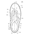
- FIG. 2 is a plan view of the shoe 100.
- the width direction of the upper 30 is simply referred to as the "width direction”
- the direction along the width direction center line La of the upper 30 is referred to as the "front-back direction”, which is a vertical direction. Is called “vertical direction”.
- the width direction, the front-back direction, and the up-down direction are orthogonal to each other.
- the direction from the heel to the toe side of the upper 30 along the center in the width direction is called “front side” and “front side”, and the opposite direction is called “rear side” and “rear side”.
- the directions from the outer foot side to the inner foot side along the width direction are referred to as “inner side” and “inner side”, and the opposite directions are referred to as “outer side” and “outer side”.
- the directions from the sole 40 to the upper 30 along the vertical direction are referred to as “upper side” and “upper side”, and the opposite sides are referred to as “lower side” and “lower side”.
- the inside from the center line La of the upper 30 is called the inner foot part, and the outside from the center line La is called the outer foot part.
- the portion corresponding to the metatarsal bone of the upper 30 is referred to as the metatarsal part
- the portion on the anterior side of the metatarsal portion of the upper 30 is referred to as the forefoot portion
- the portion posterior to the metatarsal portion of the upper 30 Is called the hind legs.
- the forefoot part generally corresponds to the phalange
- the hindfoot part roughly corresponds to the tarsal bone.
- FIG. 3 is a diagram showing a cross section of the shoe 100. This figure is a vertical cross-sectional view taken along the line BB of FIG.
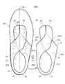
- FIG. 4 is a plan view showing the tongues 12 and 22.
- FIG. 5 is a plan view of the tongues 12 and 22 developed. The tongues 12 and 22 are provided so as to cover the opening 32 of the upper 30 extending forward from the foot entrance 31.
- the first tongue 12 on the outer foot side has a band shape extending from the first front end portion 14 on the toe side to the first rear end portion 11 on the heel side.
- the first tongue 12 has an upper edge portion 13 located generally on the upper side and a lower edge portion generally located on the lower side than the upper edge portion 13 between the first front end portion 14 and the first rear end portion 11 on the heel side. It has a part 15.
- the upper edge portion 13 has an upper protruding portion 13d constituting the foot entrance portion 31 and a side edge portion 13e provided on the front side of the upper protruding portion 13d.
- the lower edge portion 15 has a lower fixing portion 15m fixed to the upper 30 or the sole 40, and a non-fixing portion 15n provided on the front side of the lower fixing portion 15m.
- the second tongue 22 on the inner foot side has a band shape extending from the second front end portion 24 on the toe side to the second rear end portion 21 on the heel side.
- the second tongue 22 has an upper edge portion 23 located generally on the upper side and a lower edge portion generally located on the lower side than the upper edge portion 23 between the second front end portion 24 and the second rear end portion 21 on the heel side. It has a part 25.
- the upper edge portion 23 has an upper protruding portion 23d constituting the foot entrance portion 31 and a side edge portion 23e provided on the front side of the upper protruding portion 23d.
- the lower edge portion 25 has a lower fixing portion 25m fixed to the upper 30 or the sole 40, and a non-fixing portion 25n provided on the front side of the lower fixing portion 25m.
- the tongues 12 and 22 are integrated by connecting the rear end portions 11 and 21 to each other. That is, the tongues 12 and 22 are integrally and continuously formed.
- the developed view of FIG. 5 shows the tongues 12 and 22 separated at the rear ends 11 and 21.
- the rear parts of the tongues 12 and 22 form the outer shell of the foot accommodating space 30a.
- the lower portion of the rear portion of the tongues 12 and 22 is surrounded by the heel siege 38 of the upper 30, and the upper portion thereof projects upward from the heel siege 38.
- the rear portions of the tongues 12 and 22 are integrally formed with the upper 30.
- the upper protruding portions 13d and 23d of the tongues 12 and 22 project upward from the heel surrounding portion 38 of the upper 30 to form the foot insertion portion 31.
- the first tongue 12 on the outer foot side has the upper 30 and the sole 40 in the region from the vicinity of the foot entrance portion 31 to the first rear end portion 11 and the lower fixing portion 15 m thereof. It is fixed to at least one of the above by adhesion, sewing, etc.
- the lower fixing portion 25 m of the second tongue 22 on the inner foot side is fixed to at least one of the upper 30 and the sole 40 by adhesion, sewing, etc. in the region from the vicinity of the foot entrance portion 31 to the second rear end portion 21. There is.
- the insole 42 and the insole 42 are laminated on the sole 40.
- the lower fixing portions 15m and 25m of the tongues 12 and 22 are sewn and fixed to the end of the laying cloth 41 together with the lower end of the heel surrounding portion 38 of the upper 30.
- the mattress 41 is adhered to the upper surface of the sole 40.
- the insole 42 is placed so as to be in contact with the insole 41 so as to cover the lower fixed portions 15 m and 25 m and the lower end of the heel surrounding portion 38 from above.
- the first tongue 12 has a first front end portion 14 fixed to the front end portion 32f of the opening 32.
- the first tongue 12 extends rearward from the first front end portion 14 toward the outer foot side of the foot entry portion 31.
- the second tongue 22 has a second front end portion 24 that is fixed to the front end portion 32f of the opening 32.
- the second tongue 22 extends rearward from the second front end portion 24 toward the inner foot side of the foot entry portion 31.
- the first front end portion 14 is located on the inner foot side of the second front end portion 24. According to this configuration, since the first and second tongues 12 and 22 intersect at the instep, the instep is not easily exposed even if the two tongues are opened.
- the little finger side is put in first, and the toes including the thumb are put in the shoe 100 while rotating the foot.
- This rotation is, for example, counterclockwise when the right foot is viewed from behind, and there is a concern that the toe may get caught in the toe when the little finger touches the edge of the tongue. Therefore, in the present embodiment, the hierarchical relationship of the tongue is defined.
- the tongues 12 and 22 have overlapping portions 10w that are vertically overlapped with each other. In the overlapping portion 10w, the first tongue 12 is located below the second tongue 22. In this case, since the little finger moves along the back surface of the first tongue 12 along the stretching direction at the time of foot insertion, the tongue is less likely to be caught in the finger and the foot can be smoothly inserted.
- the first tongue 12 has a non-fixed portion 15n that is not fixed to the upper 30 between the vicinity of the foot entrance portion 31 and the first front end portion 14.
- the second tongue 22 has a non-fixed portion 25n that is not fixed to the upper 30 between the vicinity of the foot entrance portion 31 and the second front end portion 24.
- the tongues 12 and 24 can move relatively freely in the width direction in the vicinity of the non-fixed portions 15n and 25n. Therefore, when the instep is high, the tongues 12 and 24 expand to fit the instep, and when the instep is low, the tongues 12 and 24 approach to fit the instep.
- a notch is provided in a portion on the front side of the tongue. Specifically, as shown in FIG. 5, a notch portion 16 notched from the first front end portion 14 to the rear is provided on the outer foot side of the first tongue 12. A notch 26 notched from the second front end 24 to the rear is provided on the inner foot side of the second tongue 22.
- the cutout portion 16 is a portion in which the hatching region 16c on the outer leg side of the front end portion 14 is cut out from the overlapping portion 10w.
- the notch portion 26 is a portion in which the inner foot side of the front end portion 24 is notched from the overlapping portion 10w, similarly to the notch portion 16.
- the first front end portion 14 is separated from the second front end portion 24 in the width direction.
- the foot contact with the instep is improved as compared with the case where there is no notch.
- these gaps are largely represented for ease of understanding. It is desirable that this gap is set so that the lines extending in the front-rear direction of the first front end portion 14 and the second front end portion 24 are in contact with each other in a state where the foot is not inserted.
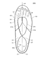
- FIG. 6 is a plan view showing the relationship between the first tongue 12 and the upper surface ridge line 94 of the instep 91.
- the upper surface ridge line 94 is a line connecting the highest points of the instep 91.
- the side edge portion 13e is a portion of the upper edge portion 13 that covers the instep 91 on the front side of the foot entry portion 31.
- the side edge portion 13e is located on the inner foot side of the center line La. From the same viewpoint, it is more desirable that the side edge portion 13e is located on the inner foot side of the portion corresponding to the upper surface ridge line 94 of the upper 30. Therefore, in the present embodiment, the first tongue 12 has a shape that covers a part of the portion corresponding to the upper surface ridge line 94 of the instep 91 of the upper 30. In this case, the side edge portion 13e on the inner foot side of the first tongue 12 is less likely to come into contact with the upper surface ridge line 94, and the foot contact with the instep 91 at this portion is further improved.
- FIG. 7 is a diagram showing fixed positions of the front end portions 14 and 24 of the tongues 12 and 22.
- the front end portions 14 and 24 may be fixed to the throat portion (front end portion 32f) of the upper 30.
- the front end portions 14 and 24 may be fixed to a portion extending rearward from the front side portion of the eyelet forming portion 34 as shown by F2 in FIG.
- the front end portions 14 and 24 may be fixed at both the F1 position and the F2 position.
- the front end portions 14 and 24 are fixed to the upper 30 by sewing.
- FIGS. 8 and 9 are development views of the first tongue 12 as viewed from the back surface, and hatching shows an extending region of the lining material.
- the tongue 12 has a surface material 12h provided on the upper surface and a lining material 12j provided on the side opposite to the surface material 12h.
- the material of the tongue surface material 12h is not limited.
- the surface material 12h may be made of polyester, nylon, artificial leather, natural leather or the like.
- a material having higher elasticity than the hindfoot side of the surface material 12h may be used on the forefoot side of the surface material 12h. In this case, the foot contact can be improved.
- the lining material 12j of the present embodiment extends to the extension range of the surface material 12h. That is, the surface material 12h is provided on the entire surface of the tongue 12, and the lining material 12j is provided on the entire back surface of the tongue 12.
- the lining material 12j may be made of a material having higher elasticity than the surface material 12h. In this case, the foot contact can be improved while ensuring the rigidity of the tongue.
- the lining material 12j may be provided only on a part of the back surface of the tongue.
- the lining material 12j may be provided only in a portion rearward from the position where the other tongue 22 intersects.
- the lining material 12j may or may not have elasticity.
- the lining material 12j may be provided in a different range between the first tongue 12 and the second tongue 22.
- the lining material 12j is provided on the entire back surface, and in the second tongue, the lining material 12j may be provided only behind the portion of the second tongue 22 that overlaps with the first tongue 12. Good. In this case, in this case, the thickness of the tongue can be reduced and the elasticity can be ensured.
- the fixing range of the lining material 12j and the surface material 12h can be set according to the desired expansion and contraction characteristics.
- the lining material 12j and the surface material 12h may be fixed to each other on their entire surfaces, or only their ends may be fixed to each other.
- the lining material 12j and the surface material 12h may be fixed to each other by sewing or tape fixing, or may be fixed to each other by an adhesive such as hot melt.
- FIG. 10 is a diagram showing an example of the thick edge portion 17 of the first tongue 12.
- the thick edge portion 17 of the first tongue 12 and the enclosed portion 18 will be described, but this description can be similarly applied to the thick edge portion and the enclosed portion of the second tongue 22.
- a thick edge portion 17 is provided around the tongue 12, and the enclosed portion 18 surrounded by the thick edge portion 17 is formed thinner than the thick edge portion 17. In this case, the thickness of the enclosed portion 18 can be reduced to ensure elasticity.
- the tongue 12 is bordered by a thick edge portion 17 formed of a cushion material, and the enclosed portion 18 surrounded by the thick edge portion 17 is formed thinner than the thick edge portion 17.
- the thick edge portion 17 may be provided on the entire circumference of the tongue 12. In the example of FIG. 10, the thick edge portion 17 is provided at the upper edge portion 13 and the edge portion in contact with the foot such as the non-fixed portion 15n of the lower edge portion 15. The thick edge portion 17 is not provided in the portion fixed to other members such as the lower fixing portion 15 m and the front end portion 14.
- the tongue structure 10 includes a first tongue 12 and a second tongue 22 provided so as to cover the opening 32 of the upper 30 extending forward from the foot entrance 31.
- the first tongue 12 has a first front end portion 14 fixed to the edge of the opening 32, extends rearward from the first front end portion 14 toward the outer foot side of the foot entry portion 31, and the second tongue 22 has a second tongue 22. It has a second front end portion 24 fixed to the edge of the opening 32, extends rearward from the second front end portion 24 toward the inner foot side of the foot entry portion 31, and the first front end portion 14 is the second front end portion 24.
- the instep is not easily exposed even when worn by a user with a high instep.
- the first tongue 12 and the second tongue 22 have overlapping portions 10w that overlap each other vertically, and in the overlapping portion 10w, the first tongue 12 is located below the second tongue 22. In this case, since the tongue is not easily caught in the finger, the shoe 100 can be smoothly entered.
- At least one of the first tongue 12 and the second tongue 22 has non-fixed portions 15n and 25n that are non-fixed to the upper 30 in front of the foot entrance portion 31.
- the range of movement of the tongue expands according to the height of the instep, so that the tongue fits the instep appropriately.
- the outer foot side of the first tongue 12 is cut out from the first front end portion 14 to the rear, and the inner foot side of the second tongue 22 is cut out from the second front end portion 24 to the rear.
- the first front end portion 14 is separated from the second front end portion 24 in the width direction. In this case, the foot contact with the instep is improved near the front end of the tongue.
- the first tongue 12 has a shape that covers a portion of the upper 30 that corresponds to the upper surface ridge line 94 of the instep 91. In this case, the feeling of foot contact on the upper ridgeline is improved.
- At least one of the first tongue 12 and the second tongue 22 has a surface material 12h provided on the upper surface and a lining material 12j provided on the side opposite to the surface material 12h.
- the lining material 12j extends over the extending range of the surface material 12h. In this case, by using a material having higher elasticity than the surface material 12h for the lining material 12j, the feeling of foot contact is improved.
- a thick edge portion 17 is provided around at least one of the first tongue 12 and the second tongue 22, and the enclosed portion 18 surrounded by the thick edge portion 17 is the thick edge portion. It is formed thinner than 17. In this case, the enclosed portion 18 surrounded by the thick edge portion 17 can be thinned to ensure the elasticity of the tongue.
- the shoe 100 of the present embodiment has the same characteristics as the tongue structure 10 because it is provided with the tongue structure 10.
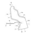
- FIG. 11 is a side view showing an example of the side shape of the first tongue 12.
- This figure is a view seen from the outer foot side, and a part of the upper 30 is cut out and the second tongue 22 is omitted.
- the side shape of the first tongue 12 will be described, but this description can be applied to the side shape of the second tongue 22 as well.
- the side surface shapes of the tongues 12 and 22 are different from those of the embodiment, and the other configurations are the same, and the side surface shapes will be mainly described.
- the first tongue 12 of the embodiment is shown by a thick solid line.
- the first tongue 12 does not cover the lateral ridgeline 96 of the forefoot portion of the foot side surface 92.
- the tongue 12 of this modified example is provided with an overhanging portion 12k (region indicated by hatching) that covers the side ridge line 96 of the forefoot portion of the foot side surface 92.
- the side ridge line 96 is a line that forms the outer contour of the instep 91 in a plan view. That is, the side ridge line 96 is a line connecting the points extending to the outermost periphery of the outer contour in a plan view.
- the overhanging portion 12k has a shape that covers a part of the portion corresponding to the side ridge line 96 of the foot side surface 92 of the forefoot portion of the upper 30.
- the overhanging portion 12k extends downward from the portion corresponding to the side ridge line 96 of the upper 30.
- the thickness of the overhanging portion 12k may be uniform, or the portion below the side ridge line 96 may be thinner than the portion above.
- the cutout portions 16 and 26 are provided in the first and second front end portions 14 and 24 , but one or both of the cutout portions 16 and 26 may not be provided. ..
- the first and second front end portions 14, 24 may be formed of, for example, a material having a thickness equal to or less than that of the enclosed portion 18.
- the rear portions of the tongues 12 and 22 are integrally formed with the upper 30, but the present invention is not limited to this.
- the tongues 12 and 22 may be formed separately from the upper 30 and connected to the upper 30 separately.
- the second tongue when attached to running shoes, may be made of a material having higher hardness and rigidity than the first tongue for the purpose of controlling running motion such as overpronation, or the second tongue may be formed. May be made thicker than the first tongue, and the second tongue may be made of a material having lower elasticity than the first tongue.
- the first tongue is made of a material that is harder and more rigid than the second tongue in order to support the foot stepping laterally.
- the first tongue may be made thicker than the second tongue, or the first tongue may be made of a material having a lower elasticity than the second tongue. Examples of such shoes include tennis shoes, basketball shoes, handball shoes and the like.
- the tongue may be made of a stretchable material so that the tightening force is applied by the tongue.
- the tongues 12 and 22 do not have to be made of separate members, and the tongues 12 and 22 may be integrated members when deployed.
- the elasticity of the overlapping portion 10w that overlaps each other vertically and the non-fixed portion in front of the overlapping portion 10w is the elasticity of the other parts of the tongues 12 and 22 and the other parts of the upper 30. May be set higher than.
- the non-fixed portion expands and contracts to absorb the difference in the height of the instep for each user, and the fit can be adjusted.
- the elasticity of the portion rearward from the overlapping portion 10w is relatively low, it is possible to suppress a decrease in the holdability of the foot.
- the non-fixed portion in front of the overlapping portion 10w is formed of a material different from the material of the rear portion.
- a configuration in which the front portion is formed of a material having a coarser mesh than the rear portion can be considered. By configuring it with a jacquard mesh, the roughness of the mesh can be changed for each part.
- a configuration using spandex for the portion having high elasticity can be adopted.
- a configuration in which the lining material of the portion having high elasticity is eliminated and a configuration in which the method of fixing the lining material of the portion is changed can also be adopted.
- front end portions 14, 24 of the tongues 12 and 22 are fixed to the upper 30 by sewing, but the present invention is not limited to this.
- the front end portions 14 and 24 may be fixed to the upper 30 by various known fixing methods other than sewing.
- the foot entry portion 31 may be composed of an upper 30.
- the rear portions of the tongues 12 and 22 form an outer shell of the foot accommodating space 30a, but the present invention is not limited to this.
- the outer shell of the foot accommodating space 30a may be composed of the upper 30.
- the present invention is related to shoes and can be used for shoes.
Landscapes
- Footwear And Its Accessory, Manufacturing Method And Apparatuses (AREA)
Priority Applications (3)
| Application Number | Priority Date | Filing Date | Title |
|---|---|---|---|
| JP2021566680A JP7490673B2 (ja) | 2019-12-26 | 2019-12-26 | シュータン構造、靴 |
| PCT/JP2019/051096 WO2021130955A1 (ja) | 2019-12-26 | 2019-12-26 | シュータン構造、靴 |
| US17/788,235 US12156569B2 (en) | 2019-12-26 | 2019-12-26 | Shoe tongue structure and shoe |
Applications Claiming Priority (1)
| Application Number | Priority Date | Filing Date | Title |
|---|---|---|---|
| PCT/JP2019/051096 WO2021130955A1 (ja) | 2019-12-26 | 2019-12-26 | シュータン構造、靴 |
Publications (1)
| Publication Number | Publication Date |
|---|---|
| WO2021130955A1 true WO2021130955A1 (ja) | 2021-07-01 |
Family
ID=76573775
Family Applications (1)
| Application Number | Title | Priority Date | Filing Date |
|---|---|---|---|
| PCT/JP2019/051096 Ceased WO2021130955A1 (ja) | 2019-12-26 | 2019-12-26 | シュータン構造、靴 |
Country Status (3)
| Country | Link |
|---|---|
| US (1) | US12156569B2 (https=) |
| JP (1) | JP7490673B2 (https=) |
| WO (1) | WO2021130955A1 (https=) |
Cited By (1)
| Publication number | Priority date | Publication date | Assignee | Title |
|---|---|---|---|---|
| WO2025177991A1 (ja) * | 2024-02-21 | 2025-08-28 | 株式会社アシックス | シューズ |
Citations (4)
| Publication number | Priority date | Publication date | Assignee | Title |
|---|---|---|---|---|
| JPH0298706U (https=) * | 1989-01-26 | 1990-08-07 | ||
| JPH0574303U (ja) * | 1992-03-14 | 1993-10-12 | 月星化成株式会社 | 靴の舌片 |
| JPH0584209U (ja) * | 1991-05-15 | 1993-11-16 | 株式会社アシックス | 運動靴の舌片 |
| JPH0928413A (ja) * | 1995-07-18 | 1997-02-04 | Asics Corp | 運動靴 |
Family Cites Families (11)
| Publication number | Priority date | Publication date | Assignee | Title |
|---|---|---|---|---|
| US994187A (en) * | 1911-02-08 | 1911-06-06 | Alfred J Dysle | Shoe-fastener. |
| US1272137A (en) * | 1917-10-18 | 1918-07-09 | Mary L Smith | Shoe-fastener. |
| US1677226A (en) * | 1927-03-07 | 1928-07-17 | Banks Mark Beal | Shoe |
| US2424777A (en) * | 1945-06-05 | 1947-07-29 | Haley Cate Company Inc | Laminated elastic material for footwear, method of making same, and improved footwear made thereby |
| JPS588491Y2 (ja) | 1980-06-09 | 1983-02-16 | 恵 明神 | 鋸屑の製造装置 |
| JPS584209U (ja) | 1981-06-30 | 1983-01-12 | 新日本製鐵株式会社 | 被冷却材のオンライン冷却装置 |
| US4486965A (en) * | 1982-05-14 | 1984-12-11 | Nike, Inc. | Footwear with overlapping closure strap means |
| US5289646A (en) * | 1989-01-26 | 1994-03-01 | Asics Corporation | Athletic shoe |
| WO2008059304A1 (en) * | 2006-11-14 | 2008-05-22 | Filip Dudal | Shoe |
| US20150096107A1 (en) * | 2013-10-03 | 2015-04-09 | Caroline Juliette Krumel | Exercise Sock with Configurable Fastening Straps |
| USD899066S1 (en) * | 2020-01-05 | 2020-10-20 | Zhigang Liu | Yoga sock |
-
2019
- 2019-12-26 JP JP2021566680A patent/JP7490673B2/ja active Active
- 2019-12-26 US US17/788,235 patent/US12156569B2/en active Active
- 2019-12-26 WO PCT/JP2019/051096 patent/WO2021130955A1/ja not_active Ceased
Patent Citations (4)
| Publication number | Priority date | Publication date | Assignee | Title |
|---|---|---|---|---|
| JPH0298706U (https=) * | 1989-01-26 | 1990-08-07 | ||
| JPH0584209U (ja) * | 1991-05-15 | 1993-11-16 | 株式会社アシックス | 運動靴の舌片 |
| JPH0574303U (ja) * | 1992-03-14 | 1993-10-12 | 月星化成株式会社 | 靴の舌片 |
| JPH0928413A (ja) * | 1995-07-18 | 1997-02-04 | Asics Corp | 運動靴 |
Cited By (1)
| Publication number | Priority date | Publication date | Assignee | Title |
|---|---|---|---|---|
| WO2025177991A1 (ja) * | 2024-02-21 | 2025-08-28 | 株式会社アシックス | シューズ |
Also Published As
| Publication number | Publication date |
|---|---|
| US20230036575A1 (en) | 2023-02-02 |
| JP7490673B2 (ja) | 2024-05-27 |
| JPWO2021130955A1 (https=) | 2021-07-01 |
| US12156569B2 (en) | 2024-12-03 |
Similar Documents
| Publication | Publication Date | Title |
|---|---|---|
| JP7203126B2 (ja) | カウンタを備えた靴 | |
| US8161666B2 (en) | Shoe construction with double upper | |
| JP4684986B2 (ja) | シューズのアッパー構造 | |
| JP4984012B2 (ja) | 踵のフィット性能を改良した靴 | |
| JP2022521944A (ja) | 摩耗ガード付きフットウェア製品 | |
| JP7476186B2 (ja) | スケートボード用シューズ | |
| KR20170134956A (ko) | 슈즈의 어퍼 구조 및 슈즈 | |
| JP2008206629A (ja) | ヒールカウンタを備えたシューズ | |
| KR20090068321A (ko) | 2 중 설포를 갖춘 신발 구조 | |
| JP2025109953A (ja) | 靴 | |
| JP6581941B2 (ja) | シューズ用アッパーおよびそれを用いたシューズ | |
| WO2021130955A1 (ja) | シュータン構造、靴 | |
| CN119866188B (zh) | 用于鞋类制品的具有鞋前部气流特征的鞋面 | |
| JP7481873B2 (ja) | シューズ用アッパー構造および当該アッパー構造を備えたシューズ | |
| JP3253635U (ja) | 靴 | |
| KR102944416B1 (ko) | 착화가 용이한 신발 | |
| JP6582109B2 (ja) | シューズ用アッパーおよびそれを用いたシューズ | |
| JP7166828B2 (ja) | フットカバー | |
| US20230354953A1 (en) | Skate | |
| JP2026066122A (ja) | シューズ | |
| JP2025127900A (ja) | シューズ | |
| US20240277108A1 (en) | Shoe | |
| JP2023163087A (ja) | 紐靴 | |
| WO2021009810A1 (ja) | シューズ |
Legal Events
| Date | Code | Title | Description |
|---|---|---|---|
| 121 | Ep: the epo has been informed by wipo that ep was designated in this application |
Ref document number: 19958027 Country of ref document: EP Kind code of ref document: A1 |
|
| ENP | Entry into the national phase |
Ref document number: 2021566680 Country of ref document: JP Kind code of ref document: A |
|
| NENP | Non-entry into the national phase |
Ref country code: DE |
|
| 122 | Ep: pct application non-entry in european phase |
Ref document number: 19958027 Country of ref document: EP Kind code of ref document: A1 |