WO2021125027A1 - センサ装置及び筐体 - Google Patents
センサ装置及び筐体 Download PDFInfo
- Publication number
- WO2021125027A1 WO2021125027A1 PCT/JP2020/045989 JP2020045989W WO2021125027A1 WO 2021125027 A1 WO2021125027 A1 WO 2021125027A1 JP 2020045989 W JP2020045989 W JP 2020045989W WO 2021125027 A1 WO2021125027 A1 WO 2021125027A1
- Authority
- WO
- WIPO (PCT)
- Prior art keywords
- sensor device
- housing
- optical device
- transmissive portion
- positive
- Prior art date
Links
Images


Classifications
-
- G—PHYSICS
- G02—OPTICS
- G02B—OPTICAL ELEMENTS, SYSTEMS OR APPARATUS
- G02B26/00—Optical devices or arrangements for the control of light using movable or deformable optical elements
- G02B26/08—Optical devices or arrangements for the control of light using movable or deformable optical elements for controlling the direction of light
- G02B26/10—Scanning systems
- G02B26/105—Scanning systems with one or more pivoting mirrors or galvano-mirrors
-
- G—PHYSICS
- G01—MEASURING; TESTING
- G01S—RADIO DIRECTION-FINDING; RADIO NAVIGATION; DETERMINING DISTANCE OR VELOCITY BY USE OF RADIO WAVES; LOCATING OR PRESENCE-DETECTING BY USE OF THE REFLECTION OR RERADIATION OF RADIO WAVES; ANALOGOUS ARRANGEMENTS USING OTHER WAVES
- G01S7/00—Details of systems according to groups G01S13/00, G01S15/00, G01S17/00
- G01S7/48—Details of systems according to groups G01S13/00, G01S15/00, G01S17/00 of systems according to group G01S17/00
- G01S7/481—Constructional features, e.g. arrangements of optical elements
- G01S7/4814—Constructional features, e.g. arrangements of optical elements of transmitters alone
-
- G—PHYSICS
- G01—MEASURING; TESTING
- G01S—RADIO DIRECTION-FINDING; RADIO NAVIGATION; DETERMINING DISTANCE OR VELOCITY BY USE OF RADIO WAVES; LOCATING OR PRESENCE-DETECTING BY USE OF THE REFLECTION OR RERADIATION OF RADIO WAVES; ANALOGOUS ARRANGEMENTS USING OTHER WAVES
- G01S17/00—Systems using the reflection or reradiation of electromagnetic waves other than radio waves, e.g. lidar systems
- G01S17/02—Systems using the reflection of electromagnetic waves other than radio waves
- G01S17/06—Systems determining position data of a target
-
- G—PHYSICS
- G01—MEASURING; TESTING
- G01S—RADIO DIRECTION-FINDING; RADIO NAVIGATION; DETERMINING DISTANCE OR VELOCITY BY USE OF RADIO WAVES; LOCATING OR PRESENCE-DETECTING BY USE OF THE REFLECTION OR RERADIATION OF RADIO WAVES; ANALOGOUS ARRANGEMENTS USING OTHER WAVES
- G01S17/00—Systems using the reflection or reradiation of electromagnetic waves other than radio waves, e.g. lidar systems
- G01S17/88—Lidar systems specially adapted for specific applications
-
- G—PHYSICS
- G01—MEASURING; TESTING
- G01S—RADIO DIRECTION-FINDING; RADIO NAVIGATION; DETERMINING DISTANCE OR VELOCITY BY USE OF RADIO WAVES; LOCATING OR PRESENCE-DETECTING BY USE OF THE REFLECTION OR RERADIATION OF RADIO WAVES; ANALOGOUS ARRANGEMENTS USING OTHER WAVES
- G01S7/00—Details of systems according to groups G01S13/00, G01S15/00, G01S17/00
- G01S7/48—Details of systems according to groups G01S13/00, G01S15/00, G01S17/00 of systems according to group G01S17/00
- G01S7/481—Constructional features, e.g. arrangements of optical elements
- G01S7/4811—Constructional features, e.g. arrangements of optical elements common to transmitter and receiver
- G01S7/4813—Housing arrangements
-
- G—PHYSICS
- G01—MEASURING; TESTING
- G01S—RADIO DIRECTION-FINDING; RADIO NAVIGATION; DETERMINING DISTANCE OR VELOCITY BY USE OF RADIO WAVES; LOCATING OR PRESENCE-DETECTING BY USE OF THE REFLECTION OR RERADIATION OF RADIO WAVES; ANALOGOUS ARRANGEMENTS USING OTHER WAVES
- G01S7/00—Details of systems according to groups G01S13/00, G01S15/00, G01S17/00
- G01S7/48—Details of systems according to groups G01S13/00, G01S15/00, G01S17/00 of systems according to group G01S17/00
- G01S7/481—Constructional features, e.g. arrangements of optical elements
- G01S7/4817—Constructional features, e.g. arrangements of optical elements relating to scanning
-
- G—PHYSICS
- G02—OPTICS
- G02B—OPTICAL ELEMENTS, SYSTEMS OR APPARATUS
- G02B26/00—Optical devices or arrangements for the control of light using movable or deformable optical elements
- G02B26/08—Optical devices or arrangements for the control of light using movable or deformable optical elements for controlling the direction of light
- G02B26/10—Scanning systems
Definitions
- the present invention relates to a sensor device and a housing.
- an optical device having a movable reflecting unit such as a MEMS (Micro Electro Mechanical Systems) mirror (for example, LiDAR (Light Detection And Ringing) or RADAR (Radio Detection And Ranking)) has been developed.
- the movable reflecting portion of the optical device scans an object such as an object existing outside the optical device by an electromagnetic wave such as infrared rays.
- the optical device may be housed in a housing.
- the optical device of Patent Document 1 has a light emitting unit, a scanning unit, and a light receiving unit. These light emitting parts, scanning parts, and light receiving parts are housed in a housing.
- One example of the problem to be solved by the present invention is to make the housing for accommodating the optical device smaller.
- the invention according to claim 1 An optical device that has a field of view that expands in one direction from a predetermined position, A housing having a transmissive portion intersecting the field of view and accommodating the optical device, With The transmissive portion includes a first side and a second side located on the opposite side of the first side. The width of the transmissive portion on the second side is narrower than the width of the transmissive portion on the first side. The second side of the transmissive portion is a sensor device located closer to the predetermined position in the one direction than the first side of the transmissive portion.
- a housing that houses an optical device that has a field of view that expands in one direction from a predetermined position. It has a transmissive part that intersects the field of view.
- the transmissive portion has a first side and a second side located on the opposite side of the first side.
- the width of the transmissive portion on the second side is narrower than the width of the transmissive portion on the first side.
- the second side of the transmissive portion is a housing located closer to the predetermined position in the one direction than the first side of the transmissive portion.
- FIG. 1 is a view of the sensor device 10 according to the embodiment as viewed diagonally from the front.
- FIG. 2 is a front view of the sensor device 10 shown in FIG.
- FIG. 3 illustrates an example of the relationship between the transmitting portion 210 and the portion of the visual field F of the optical device 100 that intersects the transmitting portion 210 (intersection portion CP) when viewed from a direction orthogonal to the transmitting portion 210. It is a figure to do.
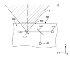
- FIG. 4 is a diagram for explaining an example of the operation of the optical device 100 housed in the housing 200 shown in FIGS. 1 and 2.
- the sensor device 10 includes an optical device 100 and a housing 200.
- the first direction X is the front-back direction of the sensor device 10.
- the positive direction of the first direction X (the direction indicated by the arrow indicating the first direction X in FIGS. 1 and 4, and the direction indicated by the dotted white circle indicating the first direction X in FIG. 2 (from the back to the front of the paper).
- Direction is the front direction of the sensor device 10.
- Negative direction of the first direction X (opposite direction of the direction indicated by the arrow indicating the first direction X in FIGS. 1 and 4, and opposite direction of the direction indicated by the dotted white circle indicating the first direction X in FIG. 2 (paper surface).
- the direction from the front to the back)) is the rear direction of the sensor device 10.
- the second direction Y intersects the first direction X, and is specifically orthogonal to each other.
- the second direction Y is the left-right direction of the sensor device 10.
- the positive direction of the second direction Y (the direction indicated by the arrow indicating the second direction Y) is the right direction when viewed from the front of the sensor device 10 (the positive direction of the first direction X).
- the negative direction of the second direction Y (the direction opposite to the direction indicated by the arrow indicating the second direction Y) is the left direction when viewed from the front of the sensor device 10 (the positive direction of the first direction X).
- the third direction Z intersects both the first direction X and the second direction Y, and is specifically orthogonal to each other.
- the third direction Z is the vertical direction of the sensor device 10.
- the positive direction of the third direction Z (the direction indicated by the arrow indicating the third direction Z in FIGS. 1 and 2 and the direction indicated by the dotted white circle indicating the third direction Z in FIG. 4 (from the back to the front of the paper).
- Direction is the upward direction of the sensor device 10.
- Negative direction of the third direction Z (opposite direction of the direction indicated by the arrow indicating the third direction Z in FIGS. 1 and 2 and the opposite direction of the direction indicated by the dotted white circle indicating the third direction Z in FIG. 4 (paper surface).
- the direction from the front to the back)) is the downward direction of the sensor device 10.
- the fourth direction U is orthogonal to the transmission portion 210, specifically, the front surface (the surface on the positive direction side of the first direction X) or the rear surface (the negative direction side of the first direction X) of the transmission portion 210.
- the direction is orthogonal to the plane).
- the fourth direction U may be, for example, a direction parallel to the thickness of the transmission portion 210.
- the fourth direction U intersects the second direction Y, and is specifically orthogonal to each other.
- the positive direction of the fourth direction U (the direction indicated by the dotted white circle indicating the fourth direction U (the direction from the back to the front of the paper surface)) is the rear surface of the transmission portion 210 (the surface on the negative direction side of the first direction X).
- the positive direction of the fourth direction U may be, for example, the normal direction of the front surface of the transmission portion 210 (the surface on the positive direction side of the first direction X).
- the negative direction of the fourth direction U (the direction opposite to the direction indicated by the dotted white circle indicating the fourth direction U (the direction from the front to the back of the paper surface)) is the front surface of the transmission portion 210 (the positive direction of the first direction X). This is the direction from the side surface) to the rear surface of the transmission portion 210 (the surface on the negative direction side of the first direction X).
- the negative direction of the fourth direction U may be, for example, the normal direction of the rear surface of the transmission portion 210 (the surface on the negative direction side of the first direction X).
- the fifth direction V intersects both the second direction Y and the fourth direction U, and is specifically orthogonal to each other.
- the fifth direction V may be in a direction parallel to the front surface (the surface on the positive direction side of the first direction X) or the rear surface (the surface on the negative direction side of the first direction X) of the transmission portion 210.
- the positive direction of the fifth direction V (the direction indicated by the arrow indicating the fifth direction V) is the direction from the second side 214 to the first side 212 of the transmission portion 210, which will be described later.
- the negative direction of the fifth direction V (the direction opposite to the direction indicated by the arrow indicating the fifth direction V) is the direction from the first side 212 to the second side 214 of the transmission portion 210.
- the sensor device 10 will be described with reference to FIGS. 1 and 2.
- the optical device 100 has a field of view F that expands from a predetermined position (details of this predetermined position will be described later) toward one direction (the positive direction of the first direction X).
- the housing 200 has a transparent portion 210.
- the transmission portion 210 intersects the visual field F.
- the housing 200 houses the optical device 100.
- the transmission portion 210 includes a first side 212 (upper side), a second side 214 (lower side), a third side 216 (left side), and a fourth side 218 (right side).
- the second side 214 is located on the opposite side of the first side 212.
- the third side 216 is located between the first side 212 and the second side 214.
- the fourth side 218 is located on the opposite side of the third side 216.
- the width (width W2 shown in FIG. 3 to be described later) in the second direction Y of the second side 214 side of the transmission portion 210 is the transmission portion 210. It is narrower than the width (width W1 shown in FIG. 3 to be described later) in the second direction Y on the first side 212 side (the upper side of the transmission portion 210 (the positive direction side of the third direction Z)).
- the second side 214 of the transmissive portion 210 is located closer to the predetermined position in the one direction (positive direction of the first direction X) than the first side 212 of the transmissive portion 210.
- the transmission portion 210 is inclined obliquely with respect to the height direction (third direction Z) of the housing 200 from the first side 212 of the transmission portion 210 to the second side 214 of the transmission portion 210.
- the transmission unit 210 raises the housing 200 toward the rear of the sensor device 10 (negative direction of the first direction X) toward the lower side of the sensor device 10 (negative direction of the third direction Z). It is tilted diagonally with respect to the vertical direction (third direction Z).
- the width of the portion of the visual field F that intersects the transmissive portion 210 (intersection portion CP) in the second direction Y on the second side 214 side of the transmissive portion 210 is the transmissive portion 210 of the intersecting portion CP of the visual field F. It is narrower than the width in the second direction Y on the first side 212 side of the above. Therefore, it is allowed that the width of the second side 214 side (lower side of the transmission portion 210) of the transmission portion 210 is shorter than the width of the first side 212 side (upper side of the transmission portion 210) of the transmission portion 210. ..
- the width of the second side 214 side (lower side of the transmission portion 210) of the transmission portion 210 is shorter than the width of the first side 212 side (upper side of the transmission portion 210) of the transmission portion 210, so that the housing 200 is reduced. It can be made smaller.
- the first side 212 of the transmission portion 210 is above the second side 214 of the transmission portion 210 (the positive direction of the third direction Z). Located on the side). Therefore, the normal direction of the front surface of the transmission portion 210 (the surface on the positive direction side of the first direction X) is from the direction toward the front of the sensor device 10 (the positive direction of the first direction X) to the lower side of the sensor device 10 (the first direction). It is tilted diagonally toward (the negative direction of the three directions Z).
- the normal direction of the front surface of the transmissive portion 210 (the surface on the positive direction side of the first direction X) is above the sensor device 10 from the direction toward the front of the sensor device 10 (the positive direction of the first direction X).
- the diagonal direction of the sensor device 10 (from the positive direction of the first direction X to the positive direction of the third direction Z). ) (For example, sunlight) is less likely to enter the inside of the housing 200 via the transmitting portion 210.
- the normal direction of the front surface of the transmission portion 210 (the surface on the positive direction side of the first direction X) is from the direction toward the front of the sensor device 10 (the positive direction of the first direction X) of the sensor device 10.
- Foreign matter for example, water droplets
- adhering to the front surface of the transmission portion 210 (the surface on the positive direction side of the first direction X) as compared with the case where the object is inclined upward (the positive direction of the third direction Z). Is less likely to stay on the front surface of the transmission portion 210 (the surface on the positive direction side of the first direction X).
- the first side 212 and the second side 214 of the transparent portion 210 do not have to be the upper side and the lower side of the transparent portion 210, respectively.
- the first side 212 and the second side 214 of the transparent portion 210 may be the lower side and the upper side of the transparent portion 210, respectively.
- the first side 212 and the second side 214 of the transmission portion 210 are both side sides (left side (side on the negative direction of the second direction Y) and right side (side on the positive direction side of the second direction Y) of the transmission portion 210. )) May be.
- the optical device 100 may be detachably attached to the housing 200, or may be non-removably fixed to the housing 200.
- the optical device 100 may be fixed to the housing 200 by, for example, a fixing tool such as a screw.
- the housing 200 may be manufactured, sold, or used in a state where the optical device 100 is not attached to the housing 200.
- the optical device 100 may be formed integrally with the housing 200 by, for example, a joining process such as welding.
- the predetermined position is the starting point at which the field of view F begins to expand. Further, the predetermined position is located inside the housing 200.
- the field of view F is a region where the optical device 100 can detect an object such as an object.
- the sensor device 10 can emit electromagnetic waves such as infrared rays from the predetermined position in any direction in the visual field F.
- the field of view F extends in two dimensions along both the second direction Y and the third direction Z when viewed from the front of the sensor device 10 (the positive direction of the first direction X). Specifically, when viewed from the front of the sensor device 10 (the positive direction of the first direction X), the upper edge of the visual field F (the edge on the positive direction side of the third direction Z) is the first of the upper edges of the visual field F. From the center in the two directions Y toward both sides of the second direction Y, the sensor device 10 is tilted downward (the negative direction of the third direction Z).
- the lower edge of the visual field F (the edge on the negative direction side of the third direction Z) is the second lower edge of the visual field F. From the center in the direction Y toward both sides of the second direction Y, the sensor device 10 is tilted downward (the negative direction of the third direction Z).
- the shape of the field of view F is not limited to this example.
- the upper edge of the field of view F (the edge on the positive direction side of the third direction Z) is parallel to the first side 212 of the transmission portion 210. It may be.
- the lower edge of the field of view F (the edge on the negative direction side of the third direction Z) is parallel to the second side 214 of the transmission portion 210. It may be.
- the transmissive portion 210 has a transparent cover that is flat and parallel to both the front surface of the transmissive portion 210 (the surface on the positive direction side of the first direction X) and the rear surface of the transmissive portion 210 (the surface on the negative direction side of the first direction X). It has become.
- the transmission portion 210 is, for example, of the rear surface of the transmission portion 210 (the surface on the negative direction side of the first direction X) of the first side 212, the second side 214, the third side 216, and the fourth side 218 of the transmission portion 210. It is attached to the housing 200 by a double-sided tape provided along at least a part thereof.
- At least one of the front surface of the transmission portion 210 (the surface on the positive direction side of the first direction X) and the rear surface of the transmission portion 210 (the surface on the negative direction side of the first direction X) is curved. It may be a lens.
- the housing 200 has a frame 220.
- the frame 220 surrounds the transparent portion 210.
- the portion of the frame 220 that extends along the first side 212 of the transmissive portion 210 is the second side 214 of the transmissive portion 210 of the frame 220. It protrudes toward the front of the sensor device 10 (the positive direction of the first direction X) from the portion extending along (the lower side of the frame 220 (the negative direction side of the third direction Z)).
- the portion of the frame 220 from the positive direction side (upper side) of the third direction Z to the center of the third direction Z is directed toward the lower side of the sensor device 10 (negative direction of the third direction Z).
- the portion of the frame 220 on the negative direction side (lower side) of the third direction Z is parallel to the height direction (third direction Z) of the housing 200.
- the portion of the frame 220 from the center of the third direction Z to the negative direction side (lower side) of the third direction Z is in front of the sensor device 10 (in the first direction X) than that according to the present embodiment.
- the housing 200 can be made smaller than the case where it protrudes in the forward direction).
- the shape of the frame 220 is not limited to the shape according to the present embodiment.
- the entire frame 220 that is, the portion of the frame 220 from the positive direction side (upper side) of the third direction Z to the negative direction side (lower side) of the third direction Z is below the sensor device 10 (third side).
- the negative direction of the direction Z it may be inclined toward the rear of the sensor device 10 (negative direction of the first direction X) with respect to the height direction (third direction Z) of the housing 200.
- the frame 220 does not have to be tilted diagonally with respect to the height direction of the housing 200 (third direction Z), and may be parallel to the height direction of the housing 200 (third direction Z). Good.
- the sensor device 10 will be further described with reference to FIG.
- the transmission portion 210 has a pentagonal shape with rounded corners.
- the first side 212 is the upper side of this pentagon.
- the second side 214 is the lower side of this pentagon.
- the third side 216 is the left side of this pentagon.
- the fourth side 218 is the right side (the remaining two sides) of this pentagon.
- the first side 212 and the second side 214 of the transmission portion 210 are parallel to the second direction Y.
- the first side 212 and the second side 214 of the transmission portion 210 do not have to be strictly parallel, and may be substantially parallel.
- At least one of the first side 212 and the second side 214 of the transmissive portion 210 may be tilted by 0 degrees or more and 5 degrees or less with respect to the second direction Y.
- the shape of the transmission portion 210 is not limited to the shape according to the present embodiment.
- the first side 212 can be, for example, a side whose at least a part is tilted from 0 degree or more and less than 45 degrees from the positive direction or negative direction of the second direction Y to the positive direction or negative direction of the fifth direction V. Further, the first side 212 may not be linearly extended, and at least a part of the first side 212 may be curved. In the present embodiment, the first side 212 is parallel to the second direction Y. However, the shape of the first side 212 is not limited to the shape according to the present embodiment. For example, the first side 212 may be inclined toward the negative direction of the fifth direction V from the center of the first side 212 in the second direction Y toward both sides of the second direction Y.
- the first side 212 may be substantially parallel to the upper edge (the edge on the positive direction side of the fifth direction V) of the intersecting portion CP of the visual field F.
- the first side 212 may be tilted by, for example, 0 degrees or more and 5 degrees or less with respect to the upper edge of the intersecting portion CP of the visual field F.
- the second side 214 can be, for example, a side whose at least a part is tilted from 0 degree or more and less than 45 degrees from the positive direction or the negative direction of the second direction Y to the positive direction or the negative direction of the fifth direction V. Further, the second side 214 may not be linearly extended, and at least a part of the second side 214 may be curved. In the present embodiment, the second side 214 is parallel to the second direction Y. However, the shape of the second side 214 is not limited to the shape according to the present embodiment. For example, the second side 214 may be inclined toward the negative direction of the fifth direction V from the center of the second side 214 in the second direction Y toward both sides of the second direction Y.
- the second side 214 may be substantially parallel to the lower edge of the intersecting portion CP of the visual field F (the edge on the negative direction side of the fifth direction V).
- the second side 214 may be tilted by, for example, 0 degrees or more and 5 degrees or less with respect to the lower edge of the intersecting portion CP of the visual field F.
- the third side 216 can be, for example, a side whose at least a part is tilted from 0 degree or more and 45 degrees or less from the positive direction or negative direction of the fifth direction V to the positive direction or negative direction of the second direction Y. Further, the third side 216 may not be linearly extended, and at least a part of the third side 216 may be curved. In this embodiment, the third side 216 is parallel to the fifth direction V. However, the shape of the third side 216 is not limited to the shape according to the present embodiment.
- the third side 216 (for example, a portion from the center of the fifth direction V to the negative direction side of the fifth direction V) is in the positive direction of the second direction Y as it goes in the negative direction of the fifth direction V. It may be tilted toward. That is, at least a part of the third side 216 may be substantially parallel to the left edge (the edge on the negative direction side of the second direction Y) of the intersecting portion CP of the visual field F.
- the third side 216 may be tilted, for example, 0 degrees or more and 5 degrees or less with respect to the left edge of the intersecting portion CP of the visual field F.
- the fourth side 218 can be, for example, a side whose at least a part is tilted from 0 degree or more and 45 degrees or less from the positive direction or negative direction of the fifth direction V to the positive direction or negative direction of the second direction Y. Further, the fourth side 218 may not be linearly extended, and at least a part of the fourth side 218 may be curved. In the present embodiment, the portion of the fourth side 218 on the positive direction side of the fifth direction V is parallel to the fifth direction V. Further, the portion of the fourth side 218 from the central portion of the fifth direction V to the negative direction side of the fifth direction V is inclined toward the negative direction of the second direction Y as it goes toward the negative direction of the fifth direction V. ing.
- the fourth side 218 (the portion from the center of the fifth direction V to the negative direction side of the fifth direction V) is the right edge of the intersecting portion CP of the visual field F (the positive direction side of the second direction Y). It is substantially parallel to the edge).
- the fourth side 218 may be tilted, for example, 0 degrees or more and 5 degrees or less with respect to the right edge of the intersecting portion CP of the visual field F.
- the shape of the fourth side 218 is not limited to the shape according to the present embodiment.
- the entire fourth side 218 may be parallel to the fifth direction V.
- the width W1 in the second direction Y on the first side 212 side of the transmission portion 210 is, for example, a portion between the first side 212 and the third side 216 (in FIG. 3, the first side 212 and the third side 216
- the second between the rounded corner between the first side 212 and the fourth side 218 (the rounded corner between the first side 212 and the fourth side 218 in FIG. 3). It can be specified as a distance in the direction Y.
- the method of defining the width W1 in the second direction Y on the first side 212 side of the transmissive portion 210 is not limited to this example.
- the width W2 in the second direction Y on the second side 214 side of the transmission portion 210 is, for example, a portion between the second side 214 and the third side 216 (in FIG. 3, the second side 214 and the third side 216
- the second between the rounded corner between the second side 214 and the fourth side 218 (the rounded corner between the second side 214 and the fourth side 218 in FIG. 3). It can be specified as a distance in the direction Y.
- the method of defining the width W2 in the second direction Y on the second side 214 side of the transmissive portion 210 is not limited to this example.
- the distance G1 in the fifth direction V between the end on the positive direction side) can be, for example, 10% or more of the length of the transmission portion 210 in the fifth direction V.
- the end of the transmissive portion 210 in the fifth direction V on the second side 214 side (negative direction side of the fifth direction V) and the second side 214 side of the intersection CP of the visual field F in the fifth direction V can be, for example, 20% or more of the length of the transmission portion 210 in the fifth direction V.
- the distance G1 in the fifth direction V between the end of the intersection portion CP of the visual field F in the fifth direction V on the first side 212 side (the positive direction side of the fifth direction V) is the fifth direction of the transmission portion 210. It can be, for example, 20% or less of the length in V. From the same viewpoint, the end of the transmissive portion 210 in the fifth direction V on the second side 214 side (negative direction side of the fifth direction V) and the second side 214 side of the intersection CP of the visual field F in the fifth direction V.
- the distance G2 in the fifth direction V between the end (on the negative direction side of the fifth direction V) can be, for example, 30% or less of the length of the transmission portion 210 in the fifth direction V.
- the width W1 in the second direction Y of the first side 212 side (positive direction side of the fifth direction V) of the portion 210 is the first side 212 side (positive direction side of the fifth direction V) of the intersecting portion CP of the visual field F. It can be, for example, 110% or more of the width W3 in the second direction Y of.
- the width W2 in the second direction Y on the second side 214 side (negative direction side of the fifth direction V) of the transmission portion 210 is the second side 214 side (fifth direction) of the intersecting portion CP of the visual field F. It can be, for example, 110% or more of the width W4 in the second direction Y (on the negative side of V).
- the width W1 of the transmission portion 210 on the first side 212 side (positive direction side of the fifth direction V) in the second direction Y is , For example, 120% or less of the width W3 in the second direction Y on the first side 212 side (the positive direction side of the fifth direction V) of the intersecting portion CP of the visual field F.
- the width W2 in the second direction Y on the second side 214 side (negative direction side of the fifth direction V) of the transmission portion 210 is the second side 214 side (fifth direction) of the intersecting portion CP of the visual field F. It can be, for example, 120% or less of the width W4 in the second direction Y (on the negative side of V).
- the optical device 100 includes a transmission unit 110, a movable reflection unit 120, a reception unit 130, and a beam splitter 140.
- the transmitting unit 110, the movable reflecting unit 120, the receiving unit 130, and the beam splitter 140 are schematically located in a plane parallel to both the first direction X and the second direction Y.
- the transmitting unit 110, the movable reflecting unit 120, the receiving unit 130, and the beam splitter 140 do not have to be located in a plane parallel to both the first direction X and the second direction Y. It may be located in a plane parallel to both the first direction X and the second direction Y.
- the electromagnetic waves propagating through the transmission unit 110, the movable reflection unit 120, the reception unit 130, and the beam splitter 140 are indicated by broken lines.
- the transmission unit 110 transmits electromagnetic waves.
- the electromagnetic wave transmitted by the transmitter 110 is light, specifically infrared.
- the electromagnetic wave transmitted by the transmitting unit 110 may be light having a wavelength different from the wavelength of infrared rays (for example, visible light or ultraviolet light), or an electromagnetic wave having a wavelength different from the wavelength of light (for example, radio wave). There may be.
- the transmission unit 110 transmits a pulse wave.
- the transmission unit 110 may transmit a continuous wave (CW).
- the transmitter 110 is an element (eg, a laser diode (LD)) capable of converting electrical energy (eg, current) into electromagnetic waves.
- LD laser diode
- the electromagnetic wave transmitted from the transmission unit 110 passes through the beam splitter 140, enters the movable reflection unit 120, and is reflected by the movable reflection unit 120.
- the movable reflection unit 120 is, for example, a MEMS (Micro Electro Mechanical Systems) mirror.
- the movable reflection unit 120 is located at the predetermined position.
- the electromagnetic wave reflected by the movable reflecting unit 120 passes through the transmitting unit 210 and is emitted toward the outside of the sensor device 10.
- the electromagnetic wave emitted toward the outside of the sensor device 10 is incident on an object (not shown in FIG. 4) such as an object existing outside the sensor device 10, and is reflected or scattered by the object.
- the electromagnetic wave reflected or scattered by the object passes through the transmitting portion 210 and is incident on the movable reflecting portion 120.
- the electromagnetic wave incident on the movable reflection unit 120 is incident on the reception unit 130 through the reflection by the movable reflection unit 120 and the reflection by the beam splitter 140 in this order.
- the receiving unit 130 receives the electromagnetic wave incident on the receiving unit 130.
- the receiver 130 is an element (eg, an avalanche photodiode (APD)) capable of converting electromagnetic waves into electrical energy (eg, current).
- APD avalanche photodiode
- the sensor device 10 is, for example, LiDAR (Light Detection And Ringing).
- the sensor device 10 measures the distance between the sensor device 10 and an object such as an object existing outside the sensor device 10 based on ToF (Time of Flight).
- ToF Time of Flight
- the sensor device 10 is present at the time when the electromagnetic wave is transmitted from the sensor device 10 (for example, the time when the electromagnetic wave is transmitted from the transmission unit 110) and the time when the sensor device 10 is transmitted and is outside the sensor device 10. The distance is calculated based on the difference between the time when the electromagnetic wave reflected or scattered by the target object is received by the sensor device 10 (for example, the time when the electromagnetic wave is received by the receiving unit 130).
- the field of view F expands toward the front of the sensor device 10 (the positive direction of the first direction X).
- the movable reflector 120 is swingable around the shaft 122.
- the shaft 122 extends along the third direction Z.
- the field of view F of the optical device 100 is determined according to the maximum swing angle of the movable reflecting unit 120.
- the movable reflecting unit 120 swings counterclockwise by the maximum swing angle of the optical device 100 when viewed from the positive direction of the third direction Z, it is transmitted from the transmitting unit 110 and reflected by the movable reflecting unit 120.
- the electromagnetic wave passes through one end of the visual field F (the left end of the visual field F in FIG. 4).
- the electromagnetic wave transmitted from the transmitting unit 110 and reflected by the movable reflecting unit 120 Passes through the other end of the field of view F on the opposite side of the one end (the right end of the field of view F in FIG. 4).
- the swing angle of the movable reflection unit 120 is 0 degrees when viewed from the positive direction of the third direction Z, the electromagnetic wave transmitted from the transmission unit 110 and reflected by the movable reflection unit 120 is centered on the field of view F. pass.
- the movable reflecting portion 120 intersects both the above-mentioned one direction (positive direction of the first direction X) and the extending direction of the axis 122 (third direction Z), specifically, in a direction orthogonal to each other (second direction Y). It can also swing around a shaft (not shown) that extends along it. Therefore, when viewed from the positive or negative direction of the second direction Y, the field of view F expands toward the front of the sensor device 10 (the positive direction of the first direction X).
- the optical device 100 is a coaxial type LiDAR. That is, the axis through which the electromagnetic wave emitted from the optical device 100 (the electromagnetic wave emitted toward the outside of the optical device 100 by the movable reflecting unit 120) passes and the electromagnetic wave returning to the optical device 100 (the electromagnetic wave emitted from the optical device 100 and emitted from the optical device 100) are passed.
- the axis through which the electromagnetic wave (electromagnetic wave that is reflected or scattered by an object existing outside the optical device 100 and is incident on the movable reflecting unit 120) passes is aligned with the optical device 100.
- the optical device 100 may be a biaxial LiDAR. That is, the optical device 100 does not have to have the movable reflection unit 120.
- the axis through which the electromagnetic wave emitted from the optical device 100 passes and the electromagnetic wave returning to the optical device 100 are reflected or scattered.
- the axis through which the electromagnetic wave incident on the optical device 100 passes is displaced from each other.
- the field of view F of the optical device 100 is the field of view of an optical scanning device such as LiDAR.
- the field of view F of the optical device 100 may be the field of view of an imaging device such as a camera.
Abstract
光学装置(100)は、所定位置から一方向に向かうにつれて拡大する視野(F)を有している。筐体(200)は、透過部(210)を有している。透過部(210)は、視野(F)と交差している。筐体(200)は、光学装置(100)を収容している。透過部(210)は、第1辺(212)及び第2辺(214)を含んでいる。第2辺(214)は、第1辺(212)の反対側に位置している。透過部(210)の第2辺(214)側の幅は、透過部(210)の第1辺(212)側の幅より狭くなっている。透過部(210)の第2辺(214)は、透過部(210)の第1辺(212)よりも、上記一方向において上記所定位置の近くに位置している。
Description
本発明は、センサ装置及び筐体に関する。
近年、MEMS(Micro Electro Mechanical Systems)ミラー等の可動反射部を有する光学装置(例えば、LiDAR(Light Detection And Ranging)又はRADAR(RAdio Detection And Ranging))が開発されている。光学装置の可動反射部は、赤外線等の電磁波によって、光学装置の外部に存在する物体等の対象を走査する。
例えば特許文献1に記載されているように、光学装置は、筐体に収容されることがある。特許文献1の光学装置は、投光部、スキャン部及び受光部を有している。これらの投光部、スキャン部及び受光部は、筐体に収容されている。
光学装置を収容する筐体には、光学装置から出射される電磁波を透過させる透過部を設ける必要がある。筐体は、当該筐体を設置するスペース等、様々な要請により、小さいことが望ましい。
本発明が解決しようとする課題としては、光学装置を収容する筐体を小さくすることが一例として挙げられる。
請求項1に記載の発明は、
所定位置から一方向に向かうにつれて拡大する視野を有する光学装置と、
前記視野と交差する透過部を有し、前記光学装置を収容する筐体と、
を備え、
前記透過部は、第1辺と、前記第1辺の反対側に位置する第2辺と、を含み、
前記透過部の前記第2辺側の幅は、前記透過部の前記第1辺側の幅より狭く、
前記透過部の前記第2辺は、前記透過部の前記第1辺よりも、前記一方向において前記所定位置の近くに位置している、センサ装置である。
所定位置から一方向に向かうにつれて拡大する視野を有する光学装置と、
前記視野と交差する透過部を有し、前記光学装置を収容する筐体と、
を備え、
前記透過部は、第1辺と、前記第1辺の反対側に位置する第2辺と、を含み、
前記透過部の前記第2辺側の幅は、前記透過部の前記第1辺側の幅より狭く、
前記透過部の前記第2辺は、前記透過部の前記第1辺よりも、前記一方向において前記所定位置の近くに位置している、センサ装置である。
請求項5に記載の発明は、
所定位置から一方向に向かうにつれて拡大する視野を有する光学装置を収容する筐体であって、
前記視野と交差する透過部を備え、
前記透過部は、第1辺と、前記第1辺の反対側に位置する第2辺と、を有し、
前記透過部の前記第2辺側の幅は、前記透過部の前記第1辺側の幅より狭く、
前記透過部の前記第2辺は、前記透過部の前記第1辺よりも、前記一方向において前記所定位置の近くに位置している、筐体である。
所定位置から一方向に向かうにつれて拡大する視野を有する光学装置を収容する筐体であって、
前記視野と交差する透過部を備え、
前記透過部は、第1辺と、前記第1辺の反対側に位置する第2辺と、を有し、
前記透過部の前記第2辺側の幅は、前記透過部の前記第1辺側の幅より狭く、
前記透過部の前記第2辺は、前記透過部の前記第1辺よりも、前記一方向において前記所定位置の近くに位置している、筐体である。
以下、本発明の実施の形態について、図面を用いて説明する。なお、すべての図面において、同様な構成要素には同様の符号を付し、適宜説明を省略する。
図1は、実施形態に係るセンサ装置10を斜め前から見た図である。図2は、図1に示したセンサ装置10の前面図である。図3は、透過部210に直交する方向から見た場合における、透過部210と、光学装置100の視野Fのうち透過部210と交差する部分(交差部分CP)と、の関係の一例を説明するための図である。図4は、図1及び図2に示した筐体200に収容される光学装置100の動作の一例を説明するための図である。
センサ装置10は、光学装置100及び筐体200を備えている。
各図において、第1方向Xは、センサ装置10の前後方向である。第1方向Xの正方向(図1及び図4において第1方向Xを示す矢印によって示される方向、図2において第1方向Xを示す点付き白丸によって示される方向(紙面の奥から手前に向かう方向))は、センサ装置10の前方向である。第1方向Xの負方向(図1及び図4において第1方向Xを示す矢印によって示される方向の反対方向、図2において第1方向Xを示す点付き白丸によって示される方向の反対方向(紙面の手前から奥に向かう方向))は、センサ装置10の後方向である。第2方向Yは、第1方向Xに交差しており、具体的には直交している。第2方向Yは、センサ装置10の左右方向である。第2方向Yの正方向(第2方向Yを示す矢印によって示される方向)は、センサ装置10の前方(第1方向Xの正方向)から見て右方向である。第2方向Yの負方向(第2方向Yを示す矢印によって示される方向の反対方向)は、センサ装置10の前方(第1方向Xの正方向)から見て左方向である。第3方向Zは、第1方向X及び第2方向Yの双方に交差しており、具体的には直交している。第3方向Zは、センサ装置10の上下方向である。第3方向Zの正方向(図1及び図2において第3方向Zを示す矢印によって示される方向、図4において第3方向Zを示す点付き白丸によって示される方向(紙面の奥から手前に向かう方向))は、センサ装置10の上方向である。第3方向Zの負方向(図1及び図2において第3方向Zを示す矢印によって示される方向の反対方向、図4において第3方向Zを示す点付き白丸によって示される方向の反対方向(紙面の手前から奥に向かう方向))は、センサ装置10の下方向である。
図3において、第4方向Uは、透過部210に直交する、具体的には、透過部210の前面(第1方向Xの正方向側の面)又は後面(第1方向Xの負方向側の面)に直交する方向である。第4方向Uは、例えば、透過部210の厚さに平行な方向であってもよい。第4方向Uは、第2方向Yに交差しており、具体的には直交している。第4方向Uの正方向(第4方向Uを示す点付き白丸によって示される方向(紙面の奥から手前に向かう方向))は、透過部210の後面(第1方向Xの負方向側の面)から透過部210の前面(第1方向Xの正方向側の面)に向かう方向である。第4方向Uの正方向は、例えば、透過部210の前面(第1方向Xの正方向側の面)の法線方向であってもよい。第4方向Uの負方向(第4方向Uを示す点付き白丸によって示される方向の反対方向(紙面の手前から奥に向かう方向))は、透過部210の前面(第1方向Xの正方向側の面)から透過部210の後面(第1方向Xの負方向側の面)に向かう方向である。第4方向Uの負方向は、例えば、透過部210の後面(第1方向Xの負方向側の面)の法線方向であってもよい。第5方向Vは、第2方向Y及び第4方向Uの双方に交差しており、具体的に直交している。第5方向Vは、透過部210の前面(第1方向Xの正方向側の面)又は後面(第1方向Xの負方向側の面)に平行な方向であってもよい。第5方向Vの正方向(第5方向Vを示す矢印によって示される方向)は、後述する透過部210の第2辺214から第1辺212に向かう方向である。第5方向Vの負方向(第5方向Vを示す矢印によって示される方向の反対方向)は、透過部210の第1辺212から第2辺214に向かう方向である。
図1及び図2を用いて、センサ装置10について説明する。
光学装置100は、所定位置(この所定位置の詳細は後述する。)から一方向(第1方向Xの正方向)に向かうにつれて拡大する視野Fを有している。筐体200は、透過部210を有している。透過部210は、視野Fと交差している。筐体200は、光学装置100を収容している。透過部210は、第1辺212(上辺)、第2辺214(下辺)、第3辺216(左辺)及び第4辺218(右辺)を含んでいる。第2辺214は、第1辺212の反対側に位置している。第3辺216は、第1辺212と第2辺214との間に位置している。第4辺218は、第3辺216の反対側に位置している。透過部210の第2辺214側(透過部210の下部側(第3方向Zの負方向側))の第2方向Yにおける幅(後述する図3に示す幅W2)は、透過部210の第1辺212側(透過部210の上部側(第3方向Zの正方向側))の第2方向Yにおける幅(後述する図3に示す幅W1)より狭くなっている。透過部210の第2辺214は、透過部210の第1辺212よりも、上記一方向(第1方向Xの正方向)において上記所定位置の近くに位置している。すなわち、透過部210は、透過部210の第1辺212から透過部210の第2辺214にかけて、筐体200の高さ方向(第3方向Z)に対して斜めに傾いている。具体的には、透過部210は、センサ装置10の下方(第3方向Zの負方向)に向かうにつれて、センサ装置10の後方(第1方向Xの負方向)に向けて筐体200の高さ方向(第3方向Z)に対して斜めに傾いている。
本実施形態において、視野Fのうち透過部210と交差する部分(交差部分CP)の透過部210の第2辺214側の第2方向Yにおける幅は、視野Fの交差部分CPの透過部210の第1辺212側の第2方向Yにおける幅より狭くなっている。したがって、透過部210の第2辺214側(透過部210の下部側)の幅を透過部210の第1辺212側(透過部210の上部側)の幅より短くすることが許容されている。したがって、透過部210の第2辺214側(透過部210の下部側)の幅を透過部210の第1辺212側(透過部210の上部側)の幅より短くした分、筐体200を小さくすることができる。
さらに本実施形態においては、筐体200の高さ方向(第3方向Z)において、透過部210の第1辺212は、透過部210の第2辺214より上側(第3方向Zの正方向側)に位置している。したがって、透過部210の前面(第1方向Xの正方向側の面)の法線方向は、センサ装置10の前方に向かう方向(第1方向Xの正方向)からセンサ装置10の下方(第3方向Zの負方向)に向けて斜めに傾いている。この場合、透過部210の前面(第1方向Xの正方向側の面)の法線方向が、センサ装置10の前方に向かう方向(第1方向Xの正方向)からセンサ装置10の上方(第3方向Zの正方向)に向けて斜めに傾いている場合と比較して、センサ装置10の斜め上(第1方向Xの正方向から第3方向Zの正方向に向けて斜めの方向)からのノイズ(例えば、太陽光)が透過部210を経由して筐体200の内部に入り込みにくくなる。また上述した場合、透過部210の前面(第1方向Xの正方向側の面)の法線方向が、センサ装置10の前方に向かう方向(第1方向Xの正方向)からセンサ装置10の上方(第3方向Zの正方向)に向けて斜めに傾いている場合と比較して、透過部210の前面(第1方向Xの正方向側の面)に付着した異物(例えば、水滴)が透過部210の前面(第1方向Xの正方向側の面)に留まりにくくなる。
なお、透過部210の第1辺212及び第2辺214は、それぞれ、透過部210の上辺及び下辺でなくてもよい。例えば、透過部210の第1辺212及び第2辺214は、それぞれ、透過部210の下辺及び上辺であってもよい。或いは、透過部210の第1辺212及び第2辺214は、透過部210の両側辺(左辺(第2方向Yの負方向側の辺)及び右辺(第2方向Yの正方向側の辺))であってもよい。
光学装置100は、筐体200に取り外し可能に取り付けられていてもよいし、又は筐体200から取り外し不可能に固定されていてもよい。光学装置100が筐体200に取り外し可能に取り付けられている場合、光学装置100は、例えば、ネジ等の固定具によって筐体200に固定されていてもよい。またこの場合、筐体200は、光学装置100が筐体200に取り付けられていない状態で製造され、販売される等、使用されてもよい。光学装置100が筐体200から取り外し不可能に固定されている場合、光学装置100は、例えば溶接等の接合処理によって、筐体200と一体となって形成されていてもよい。
上記所定位置は、視野Fが拡大し始める起点である。また、上記所定位置は、筐体200の内部に位置している。視野Fは、光学装置100が物体等の対象を検出可能な領域である。例えば、センサ装置10は、上記所定位置から視野F内のいずれかの方向に向けて赤外線等の電磁波を出射可能になっている。
視野Fは、センサ装置10の前方(第1方向Xの正方向)から見て、第2方向Y及び第3方向Zの双方に沿って2次元に亘って広がっている。具体的には、センサ装置10の前方(第1方向Xの正方向)から見て、視野Fの上縁(第3方向Zの正方向側の縁)は、視野Fの当該上縁の第2方向Yにおける中心から第2方向Yの両側に向かうにつれて、センサ装置10の下方(第3方向Zの負方向)に向けて傾いている。同様にして、センサ装置10の前方(第1方向Xの正方向)から見て、視野Fの下縁(第3方向Zの負方向側の縁)は、視野Fの当該下縁の第2方向Yにおける中心から第2方向Yの両側に向かうにつれて、センサ装置10の下方(第3方向Zの負方向)に向けて傾いている。しかしながら、視野Fの形状は、この例に限定されるものでない。例えば、センサ装置10の前方(第1方向Xの正方向)から見て、視野Fの上縁(第3方向Zの正方向側の縁)は、透過部210の第1辺212と平行になっていてもよい。また、センサ装置10の前方(第1方向Xの正方向)から見て、視野Fの下縁(第3方向Zの負方向側の縁)は、透過部210の第2辺214と平行になっていてもよい。
透過部210は、透過部210の前面(第1方向Xの正方向側の面)及び透過部210の後面(第1方向Xの負方向側の面)の双方とも平坦かつ平行な透明カバーとなっている。透過部210は、例えば、透過部210の後面(第1方向Xの負方向側の面)のうち透過部210の第1辺212、第2辺214、第3辺216及び第4辺218の少なくとも一部分に沿って設けられた両面テープによって筐体200に取り付けられている。なお、透過部210は、透過部210の前面(第1方向Xの正方向側の面)及び透過部210の後面(第1方向Xの負方向側の面)のうちの少なくとも一方が湾曲したレンズであってもよい。
筐体200は、枠220を有している。枠220は、透過部210を囲んでいる。枠220のうち透過部210の第1辺212に沿って延伸する部分(枠220の上側(第3方向Zの正方向側)の部分)は、枠220のうち透過部210の第2辺214に沿って延伸する部分(枠220の下側(第3方向Zの負方向側)の部分)よりも、センサ装置10の前方(第1方向Xの正方向)に向けて突出している。具体的には、枠220のうち第3方向Zの正方向側(上側)から第3方向Zの中央にかけての部分は、センサ装置10の下方(第3方向Zの負方向)に向かうにつれて、センサ装置10の後方(第1方向Xの負方向)に向けて筐体200の高さ方向(第3方向Z)に対して斜めに傾いている。また、枠220のうち第3方向Zの負方向側(下側)の部分は、筐体200の高さ方向(第3方向Z)に平行になっている。この場合、枠220のうち第3方向Zの中央から第3方向Zの負方向側(下側)にかけての部分が、本実施形態に係るそれよりもセンサ装置10の前方(第1方向Xの正方向)に向けて突出している場合と比較して、筐体200を小さくすることができる。しかしながら、枠220の形状は、本実施形態に係る形状に限定されない。例えば、枠220の全体、すなわち、枠220のうち第3方向Zの正方向側(上側)から第3方向Zの負方向側(下側)にかけての部分が、センサ装置10の下方(第3方向Zの負方向)に向かうにつれて、センサ装置10の後方(第1方向Xの負方向)に向けて筐体200の高さ方向(第3方向Z)に対して斜めに傾いていてもよい。或いは、枠220は、筐体200の高さ方向(第3方向Z)に対して斜めに傾いていなくてもよく、筐体200の高さ方向(第3方向Z)に平行であってもよい。
図3を用いて、センサ装置10についてさらに説明する。
本実施形態において、透過部210は、角が丸まった五角形形状を有している。第1辺212は、この五角形の上辺となっている。第2辺214は、この五角形の下辺となっている。第3辺216は、この五角形の左辺となっている。第4辺218は、この五角形の右辺(残りの2辺)となっている。透過部210の第1辺212及び第2辺214は、第2方向Yに平行になっている。透過部210の第1辺212及び第2辺214は、厳密に平行でなくてもよく、実質的に平行であってもよい。例えば、透過部210の第1辺212及び第2辺214の少なくとも一方は、第2方向Yに対して0度以上5度以下だけ傾いていてもよい。しかしながら、透過部210の形状は、本実施形態に係る形状に限定されるものではない。
第1辺212は、例えば、少なくとも一部分が第2方向Yの正方向又は負方向から第5方向Vの正方向又は負方向に向けて0度以上45度未満傾いた辺にすることができる。また、第1辺212は直線状に延伸していなくてもよく、第1辺212の少なくとも一部分は湾曲していてもよい。本実施形態において、第1辺212は、第2方向Yに平行になっている。しかしながら、第1辺212の形状は、本実施形態に係る形状に限定されるものではない。例えば、第1辺212は、第1辺212の第2方向Yにおける中心から第2方向Yの両側に向かうにつれて、第5方向Vの負方向に向けて傾いていてもよい。すなわち、第1辺212の少なくとも一部分は、視野Fの交差部分CPの上縁(第5方向Vの正方向側の縁)に実質的に平行であってもよい。例えば、第1辺212は、視野Fの交差部分CPの上縁に対して例えば0度以上5度以下傾いていてもよい。
第2辺214は、例えば、少なくとも一部分が第2方向Yの正方向又は負方向から第5方向Vの正方向又は負方向に向けて0度以上45度未満傾いた辺にすることができる。また、第2辺214は直線状に延伸していなくてもよく、第2辺214の少なくとも一部分は湾曲していてもよい。本実施形態において、第2辺214は、第2方向Yに平行になっている。しかしながら、第2辺214の形状は、本実施形態に係る形状に限定されるものではない。例えば、第2辺214は、第2辺214の第2方向Yにおける中心から第2方向Yの両側に向かうにつれて、第5方向Vの負方向に向けて傾いていてもよい。すなわち、第2辺214の少なくとも一部分は、視野Fの交差部分CPの下縁(第5方向Vの負方向側の縁)に実質的に平行であってもよい。例えば、第2辺214は、視野Fの交差部分CPの下縁に対して例えば0度以上5度以下傾いていてもよい。
第3辺216は、例えば、少なくとも一部分が第5方向Vの正方向又は負方向から第2方向Yの正方向又は負方向に向けて0度以上45度以下傾いた辺にすることができる。また、第3辺216は直線状に延伸していなくてもよく、第3辺216の少なくとも一部分は湾曲していてもよい。本実施形態において、第3辺216は、第5方向Vに平行になっている。しかしながら、第3辺216の形状は、本実施形態に係る形状に限定されるものではない。例えば、第3辺216の少なくとも一部分(例えば、第5方向Vの中央から第5方向Vの負方向側にかけての部分)は、第5方向Vの負方向に向かうにつれて第2方向Yの正方向に向けて傾いていてもよい。すなわち、第3辺216の少なくとも一部分は、視野Fの交差部分CPの左縁(第2方向Yの負方向側の縁)に実質的に平行であってもよい。例えば、第3辺216は、視野Fの交差部分CPの左縁に対して例えば0度以上5度以下傾いていてもよい。
第4辺218は、例えば、少なくとも一部分が第5方向Vの正方向又は負方向から第2方向Yの正方向又は負方向に向けて0度以上45度以下傾いた辺にすることができる。また、第4辺218は直線状に延伸していなくてもよく、第4辺218の少なくとも一部分は湾曲していてもよい。本実施形態において、第4辺218のうち第5方向Vの正方向側の部分は、第5方向Vに平行になっている。また、第4辺218のうち第5方向Vの中央部分から第5方向Vの負方向側にかけての部分は、第5方向Vの負方向に向かうにつれて第2方向Yの負方向に向けて傾いている。したがって、第4辺218の少なくとも一部分(第5方向Vの中央から第5方向Vの負方向側にかけての部分)は、視野Fの交差部分CPの右縁(第2方向Yの正方向側の縁)に実質的に平行となっている。例えば、第4辺218は、視野Fの交差部分CPの右縁に対して例えば0度以上5度以下傾いていてもよい。しかしながら、第4辺218の形状は、本実施形態に係る形状に限定されるものではない。例えば、第4辺218の全体が第5方向Vに平行であってもよい。
透過部210の第1辺212側の第2方向Yにおける幅W1は、例えば、第1辺212と第3辺216との間の部分(図3において第1辺212と第3辺216との間の丸まった角)と、第1辺212と第4辺218との間の部分(図3において第1辺212と第4辺218との間の丸まった角)と、の間の第2方向Yにおける距離として規定することができる。ただし、透過部210の第1辺212側の第2方向Yにおける幅W1の規定方法は、この例に限定されるものでない。
透過部210の第2辺214側の第2方向Yにおける幅W2は、例えば、第2辺214と第3辺216との間の部分(図3において第2辺214と第3辺216との間の丸まった角)と、第2辺214と第4辺218との間の部分(図3において第2辺214と第4辺218との間の丸まった角)と、の間の第2方向Yにおける距離として規定することができる。ただし、透過部210の第2辺214側の第2方向Yにおける幅W2の規定方法は、この例に限定されるものでない。
透過部210及び視野Fの実際の位置が例えば公差によって透過部210及び視野Fの設計の位置からずれても視野Fの交差部分CPの全体が透過部210と交差するようにする観点から、第5方向Vにおける透過部210の第1辺212側(第5方向Vの正方向側)の端と、第5方向Vにおける視野Fの交差部分CPの第1辺212側(第5方向Vの正方向側)の端と、の間の第5方向Vにおける距離G1は、透過部210の第5方向Vにおける長さの例えば10%以上にすることができる。同様の観点から、第5方向Vにおける透過部210の第2辺214側(第5方向Vの負方向側)の端と、第5方向Vにおける視野Fの交差部分CPの第2辺214側(第5方向Vの負方向側)の端と、の間の第5方向Vにおける距離G2は、透過部210の第5方向Vにおける長さの例えば20%以上にすることができる。また、透過部210の第5方向Vにおける長さが短くなるようにする観点から、第5方向Vにおける透過部210の第1辺212側(第5方向Vの正方向側)の端と、第5方向Vにおける視野Fの交差部分CPの第1辺212側(第5方向Vの正方向側)の端と、の間の第5方向Vにおける距離G1は、透過部210の第5方向Vにおける長さの例えば20%以下にすることができる。同様の観点から、第5方向Vにおける透過部210の第2辺214側(第5方向Vの負方向側)の端と、第5方向Vにおける視野Fの交差部分CPの第2辺214側(第5方向Vの負方向側)の端と、の間の第5方向Vにおける距離G2は、透過部210の第5方向Vにおける長さの例えば30%以下にすることができる。
透過部210及び視野Fの実際の位置が例えば公差によって透過部210及び視野Fの設計の位置からずれても視野Fの交差部分CPの全体が透過部210と交差するようにする観点から、透過部210の第1辺212側(第5方向Vの正方向側)の第2方向Yにおける幅W1は、視野Fの交差部分CPの第1辺212側(第5方向Vの正方向側)の第2方向Yにおける幅W3の例えば110%以上にすることができる。同様の観点から、透過部210の第2辺214側(第5方向Vの負方向側)の第2方向Yにおける幅W2は、視野Fの交差部分CPの第2辺214側(第5方向Vの負方向側)の第2方向Yにおける幅W4の例えば110%以上にすることができる。また、透過部210の第2方向Yにおける長さが短くなるようにする観点から、透過部210の第1辺212側(第5方向Vの正方向側)の第2方向Yにおける幅W1は、視野Fの交差部分CPの第1辺212側(第5方向Vの正方向側)の第2方向Yにおける幅W3の例えば120%以下にすることができる。同様の観点から、透過部210の第2辺214側(第5方向Vの負方向側)の第2方向Yにおける幅W2は、視野Fの交差部分CPの第2辺214側(第5方向Vの負方向側)の第2方向Yにおける幅W4の例えば120%以下にすることができる。
図4を用いて、センサ装置10の詳細を説明する。
光学装置100は、送信部110、可動反射部120、受信部130及びビームスプリッタ140を備えている。図4では、送信部110、可動反射部120、受信部130及びビームスプリッタ140は、模式的に、第1方向X及び第2方向Yの双方に平行な一平面内に位置している。しかしながら、実際のレイアウトにおいては、送信部110、可動反射部120、受信部130及びビームスプリッタ140は、第1方向X及び第2方向Yの双方に平行な一平面内に位置していなくてもよいし、又は第1方向X及び第2方向Yの双方に平行な一平面内に位置していてもよい。
図4では、送信部110、可動反射部120、受信部130及びビームスプリッタ140を伝搬する電磁波は、破線によって示されている。
送信部110は、電磁波を送信する。一例において、送信部110によって送信される電磁波は、光、具体的には、赤外線である。しかしながら、送信部110によって送信される電磁波は、赤外線の波長と異なる波長の光(例えば、可視光線又は紫外線)であってもよいし、又は光の波長と異なる波長の電磁波(例えば、電波)であってもよい。一例において、送信部110は、パルス波を送信する。しかしながら、送信部110は、連続波(CW)を送信してもよい。一例において、送信部110は、電気的エネルギー(例えば、電流)を電磁波に変換可能な素子(例えば、レーザダイオード(LD))である。
送信部110から送信された電磁波は、ビームスプリッタ140を透過して可動反射部120に入射し、可動反射部120によって反射される。可動反射部120は、例えば、MEMS(Micro Electro Mechanical Systems)ミラーである。可動反射部120は、上記所定位置に位置している。
可動反射部120によって反射された電磁波は、透過部210を透過してセンサ装置10の外部に向けて出射される。センサ装置10の外部に向けて出射された電磁波は、センサ装置10の外部に存在する物体等の対象(図4では不図示)に入射し、対象によって反射され、又は散乱される。対象によって反射され、又は散乱された電磁波は、透過部210を透過して可動反射部120に入射する。可動反射部120に入射した電磁波は、可動反射部120による反射及びビームスプリッタ140による反射を順に経て、受信部130に入射する。受信部130は、受信部130に入射した電磁波を受信する。一例において、受信部130は、電磁波を電気的エネルギー(例えば、電流)に変換可能な素子(例えば、アバランシェフォトダイオード(APD))である。
センサ装置10は、例えば、LiDAR(Light Detection And Ranging)である。一例において、センサ装置10は、ToF(Time of Flight)に基づいて、センサ装置10と、センサ装置10の外部に存在する物体等の対象と、の間の距離を測定する。この例において、センサ装置10は、センサ装置10から電磁波が送信された時間(例えば、送信部110から電磁波が送信された時間)と、センサ装置10から送信され、かつセンサ装置10の外部に存在する対象によって反射され、又は散乱された電磁波がセンサ装置10によって受信された時間(例えば、受信部130によって電磁波が受信された時間)と、の差に基づいて、上記距離を算出する。
第3方向Zの正方向から見て、視野Fは、センサ装置10の前方(第1方向Xの正方向)に向かうにつれて広がっている。具体的には、可動反射部120は、軸122の周りに揺動可能になっている。軸122は、第3方向Zに沿って延伸している。光学装置100の視野Fは、可動反射部120の最大揺動角に応じて決定されている。第3方向Zの正方向から見て、可動反射部120が反時計回りに光学装置100の最大揺動角だけ揺動したとき、送信部110から送信され、かつ可動反射部120によって反射された電磁波は、視野Fの一端部(図4における視野Fの左側端部)を通過する。第3方向Zの正方向から見て、可動反射部120が時計回りに光学装置100の最大揺動角だけ揺動したとき、送信部110から送信され、かつ可動反射部120によって反射された電磁波は、視野Fの上記一端部の反対側の他端部(図4における視野Fの右側端部)を通過する。第3方向Zの正方向から見て、可動反射部120の揺動角が0度であるとき、送信部110から送信され、かつ可動反射部120によって反射された電磁波は、視野Fの中心を通過する。
可動反射部120は、上記一方向(第1方向Xの正方向)及び軸122の延伸方向(第3方向Z)の双方に交差する、具体的には直交する方向(第2方向Y)に沿って延伸する軸(不図示)の周りにも揺動可能になっている。したがって、第2方向Yの正方向又は負方向から見て、視野Fは、センサ装置10の前方(第1方向Xの正方向)に向かうにつれて広がっている。
本実施形態において、光学装置100は、コアキシャル型LiDARとなっている。すなわち、光学装置100から出射される電磁波(可動反射部120によって光学装置100の外部に向けて出射された電磁波)が通過する軸と、光学装置100に戻る電磁波(光学装置100から出射されて、光学装置100の外部に存在する対象によって反射され、又は散乱されて、可動反射部120に入射する電磁波)が通過する軸と、が一致している。しかしながら、光学装置100は、バイアキシャル型LiDARであってもよい。すなわち、光学装置100は、可動反射部120を有していなくてもよい。この場合、光学装置100から出射される電磁波が通過する軸と、光学装置100に戻る電磁波(光学装置100から出射されて、光学装置100の外部に存在する対象によって反射され、又は散乱されて、光学装置100に入射する電磁波)が通過する軸と、が互いにずれるようになる。
以上、図面を参照して実施形態について述べたが、これらは本発明の例示であり、上記以外の様々な構成を採用することもできる。
例えば、本実施形態では、光学装置100の視野Fは、LiDAR等の光走査装置の視野である。しかしながら、光学装置100の視野Fは、カメラ等の撮像装置の視野であってもよい。
この出願は、2019年12月17日に出願された日本出願特願2019-227006号を基礎とする優先権を主張し、その開示の全てをここに取り込む。
10 センサ装置
100 光学装置
110 送信部
120 可動反射部
122 軸
130 受信部
140 ビームスプリッタ
200 筐体
210 透過部
212 第1辺
214 第2辺
216 第3辺
218 第4辺
220 枠
CP 交差部分
F 視野
U 第4方向
V 第5方向
X 第1方向
Y 第2方向
Z 第3方向
100 光学装置
110 送信部
120 可動反射部
122 軸
130 受信部
140 ビームスプリッタ
200 筐体
210 透過部
212 第1辺
214 第2辺
216 第3辺
218 第4辺
220 枠
CP 交差部分
F 視野
U 第4方向
V 第5方向
X 第1方向
Y 第2方向
Z 第3方向
Claims (5)
- 所定位置から一方向に向かうにつれて拡大する視野を有する光学装置と、
前記視野と交差する透過部を有し、前記光学装置を収容する筐体と、
を備え、
前記透過部は、第1辺と、前記第1辺の反対側に位置する第2辺と、を含み、
前記透過部の前記第2辺側の幅は、前記透過部の前記第1辺側の幅より狭く、
前記透過部の前記第2辺は、前記透過部の前記第1辺よりも、前記一方向において前記所定位置の近くに位置している、センサ装置。 - 請求項1に記載のセンサ装置において、
前記筐体の高さ方向において、前記透過部の前記第1辺は、前記透過部の前記第2辺より上側に位置している、センサ装置。 - 請求項1又は2に記載のセンサ装置において、
前記筐体は、前記透過部を囲む枠を有し、
前記枠のうち前記透過部の前記第1辺に沿って延伸する部分は、前記枠のうち前記透過部の前記第2辺に沿って延伸する部分よりも、前記一方向に向けて突出している、センサ装置。 - 請求項1から3までのいずれか一項に記載のセンサ装置において、
前記光学装置は、前記所定位置に位置する可動反射部を有する、センサ装置。 - 所定位置から一方向に向かうにつれて拡大する視野を有する光学装置を収容する筐体であって、
前記視野と交差する透過部を備え、
前記透過部は、第1辺と、前記第1辺の反対側に位置する第2辺と、を有し、
前記透過部の前記第2辺側の幅は、前記透過部の前記第1辺側の幅より狭く、
前記透過部の前記第2辺は、前記透過部の前記第1辺よりも、前記一方向において前記所定位置の近くに位置している、筐体。
Priority Applications (4)
| Application Number | Priority Date | Filing Date | Title |
|---|---|---|---|
| EP20903677.1A EP4050368A4 (en) | 2019-12-17 | 2020-12-10 | SENSOR DEVICE AND HOUSING |
| CN202080086121.6A CN114981678A (zh) | 2019-12-17 | 2020-12-10 | 传感器装置及壳体 |
| US17/779,527 US20230003841A1 (en) | 2019-12-17 | 2020-12-10 | Sensor device and housing |
| JP2021565524A JPWO2021125027A1 (ja) | 2019-12-17 | 2020-12-10 |
Applications Claiming Priority (2)
| Application Number | Priority Date | Filing Date | Title |
|---|---|---|---|
| JP2019-227006 | 2019-12-17 | ||
| JP2019227006 | 2019-12-17 |
Publications (1)
| Publication Number | Publication Date |
|---|---|
| WO2021125027A1 true WO2021125027A1 (ja) | 2021-06-24 |
Family
ID=76476569
Family Applications (1)
| Application Number | Title | Priority Date | Filing Date |
|---|---|---|---|
| PCT/JP2020/045989 WO2021125027A1 (ja) | 2019-12-17 | 2020-12-10 | センサ装置及び筐体 |
Country Status (5)
| Country | Link |
|---|---|
| US (1) | US20230003841A1 (ja) |
| EP (1) | EP4050368A4 (ja) |
| JP (1) | JPWO2021125027A1 (ja) |
| CN (1) | CN114981678A (ja) |
| WO (1) | WO2021125027A1 (ja) |
Citations (5)
| Publication number | Priority date | Publication date | Assignee | Title |
|---|---|---|---|---|
| JP2014190736A (ja) * | 2013-03-26 | 2014-10-06 | Denso Wave Inc | レーザレーダ装置 |
| JP2017150858A (ja) * | 2016-02-22 | 2017-08-31 | 株式会社キーエンス | 安全スキャナ |
| US20170322075A1 (en) * | 2016-05-03 | 2017-11-09 | Datalogic IP Tech, S.r.l. | Laser scanner with reduced internal optical reflection |
| JP2019128236A (ja) | 2018-01-24 | 2019-08-01 | 株式会社デンソー | ライダー装置 |
| JP2019163988A (ja) * | 2018-03-19 | 2019-09-26 | 株式会社デンソーウェーブ | 走査型レーザレーダのレーザ光透過部材、及び走査型レーザレーダ |
-
2020
- 2020-12-10 EP EP20903677.1A patent/EP4050368A4/en active Pending
- 2020-12-10 JP JP2021565524A patent/JPWO2021125027A1/ja active Pending
- 2020-12-10 CN CN202080086121.6A patent/CN114981678A/zh active Pending
- 2020-12-10 WO PCT/JP2020/045989 patent/WO2021125027A1/ja unknown
- 2020-12-10 US US17/779,527 patent/US20230003841A1/en active Pending
Patent Citations (5)
| Publication number | Priority date | Publication date | Assignee | Title |
|---|---|---|---|---|
| JP2014190736A (ja) * | 2013-03-26 | 2014-10-06 | Denso Wave Inc | レーザレーダ装置 |
| JP2017150858A (ja) * | 2016-02-22 | 2017-08-31 | 株式会社キーエンス | 安全スキャナ |
| US20170322075A1 (en) * | 2016-05-03 | 2017-11-09 | Datalogic IP Tech, S.r.l. | Laser scanner with reduced internal optical reflection |
| JP2019128236A (ja) | 2018-01-24 | 2019-08-01 | 株式会社デンソー | ライダー装置 |
| JP2019163988A (ja) * | 2018-03-19 | 2019-09-26 | 株式会社デンソーウェーブ | 走査型レーザレーダのレーザ光透過部材、及び走査型レーザレーダ |
Also Published As
| Publication number | Publication date |
|---|---|
| US20230003841A1 (en) | 2023-01-05 |
| EP4050368A4 (en) | 2023-11-08 |
| EP4050368A1 (en) | 2022-08-31 |
| CN114981678A (zh) | 2022-08-30 |
| JPWO2021125027A1 (ja) | 2021-06-24 |
Similar Documents
| Publication | Publication Date | Title |
|---|---|---|
| KR101923724B1 (ko) | 송수광 일체형 광학계 모듈 및 이를 구비하는 스캐닝 라이다 | |
| KR102210101B1 (ko) | 광학계 모듈 및 그를 갖는 스캐닝 라이다 | |
| US9048609B2 (en) | Laser emitter module and laser detecting system to which the laser emitter module is applied | |
| JP6737296B2 (ja) | 対象物検出装置 | |
| WO2020200206A1 (zh) | 光扫描装置和激光雷达 | |
| CN211236225U (zh) | 一种大视场激光雷达光机系统 | |
| JP7473067B2 (ja) | 光走査装置、物体検出装置及びセンシング装置 | |
| JP2018059847A (ja) | レーザレーダ装置 | |
| WO2021125027A1 (ja) | センサ装置及び筐体 | |
| JP7234816B2 (ja) | 測距装置 | |
| JP6676974B2 (ja) | 対象物検出装置 | |
| CN114814791A (zh) | 一种激光雷达 | |
| JP2021117142A (ja) | センサ装置、筐体及びカバー部 | |
| WO2021117571A1 (ja) | センサ装置 | |
| WO2021117570A1 (ja) | センサ装置 | |
| KR102486473B1 (ko) | 차량용 스캐닝 라이다 광학계 및 그를 포함하는 차량용 스캐닝 라이다 | |
| WO2021153181A1 (ja) | センサ装置、筐体及びカバー部 | |
| KR102486472B1 (ko) | 스캐닝 라이다 광원모듈용 렌즈 및 그가 설치된 광원모듈 | |
| JP2021076408A (ja) | センサ装置 | |
| US11302731B2 (en) | Electromagnetic wave detection apparatus and information acquisition system | |
| KR102636500B1 (ko) | 전방위 시야각을 갖는 라이다 시스템 | |
| CN210347921U (zh) | 一种激光发射装置以及激光雷达系统 | |
| EP4328552A1 (en) | Electromagnetic wave detecting device | |
| JP2021117141A (ja) | センサ装置、筐体及びカバー部 | |
| JP2021117140A (ja) | センサ装置、筐体及びカバー部 |
Legal Events
| Date | Code | Title | Description |
|---|---|---|---|
| 121 | Ep: the epo has been informed by wipo that ep was designated in this application |
Ref document number: 20903677 Country of ref document: EP Kind code of ref document: A1 |
|
| ENP | Entry into the national phase |
Ref document number: 2021565524 Country of ref document: JP Kind code of ref document: A |
|
| ENP | Entry into the national phase |
Ref document number: 2020903677 Country of ref document: EP Effective date: 20220523 |
|
| NENP | Non-entry into the national phase |
Ref country code: DE |