WO2021117509A1 - クリーナ - Google Patents
クリーナ Download PDFInfo
- Publication number
- WO2021117509A1 WO2021117509A1 PCT/JP2020/044272 JP2020044272W WO2021117509A1 WO 2021117509 A1 WO2021117509 A1 WO 2021117509A1 JP 2020044272 W JP2020044272 W JP 2020044272W WO 2021117509 A1 WO2021117509 A1 WO 2021117509A1
- Authority
- WO
- WIPO (PCT)
- Prior art keywords
- component
- filter
- main body
- body housing
- holder
- Prior art date
- Legal status (The legal status is an assumption and is not a legal conclusion. Google has not performed a legal analysis and makes no representation as to the accuracy of the status listed.)
- Ceased
Links
Images





Classifications
-
- A—HUMAN NECESSITIES
- A47—FURNITURE; DOMESTIC ARTICLES OR APPLIANCES; COFFEE MILLS; SPICE MILLS; SUCTION CLEANERS IN GENERAL
- A47L—DOMESTIC WASHING OR CLEANING; SUCTION CLEANERS IN GENERAL
- A47L5/00—Structural features of suction cleaners
- A47L5/12—Structural features of suction cleaners with power-driven air-pumps or air-compressors, e.g. driven by motor vehicle engine vacuum
- A47L5/22—Structural features of suction cleaners with power-driven air-pumps or air-compressors, e.g. driven by motor vehicle engine vacuum with rotary fans
- A47L5/24—Hand-supported suction cleaners
-
- A—HUMAN NECESSITIES
- A47—FURNITURE; DOMESTIC ARTICLES OR APPLIANCES; COFFEE MILLS; SPICE MILLS; SUCTION CLEANERS IN GENERAL
- A47L—DOMESTIC WASHING OR CLEANING; SUCTION CLEANERS IN GENERAL
- A47L5/00—Structural features of suction cleaners
- A47L5/12—Structural features of suction cleaners with power-driven air-pumps or air-compressors, e.g. driven by motor vehicle engine vacuum
- A47L5/22—Structural features of suction cleaners with power-driven air-pumps or air-compressors, e.g. driven by motor vehicle engine vacuum with rotary fans
- A47L5/28—Suction cleaners with handles and nozzles fixed on the casings, e.g. wheeled suction cleaners with steering handle
-
- A—HUMAN NECESSITIES
- A47—FURNITURE; DOMESTIC ARTICLES OR APPLIANCES; COFFEE MILLS; SPICE MILLS; SUCTION CLEANERS IN GENERAL
- A47L—DOMESTIC WASHING OR CLEANING; SUCTION CLEANERS IN GENERAL
- A47L9/00—Details or accessories of suction cleaners, e.g. mechanical means for controlling the suction or for effecting pulsating action; Storing devices specially adapted to suction cleaners or parts thereof; Carrying-vehicles specially adapted for suction cleaners
- A47L9/10—Filters; Dust separators; Dust removal; Automatic exchange of filters
-
- A—HUMAN NECESSITIES
- A47—FURNITURE; DOMESTIC ARTICLES OR APPLIANCES; COFFEE MILLS; SPICE MILLS; SUCTION CLEANERS IN GENERAL
- A47L—DOMESTIC WASHING OR CLEANING; SUCTION CLEANERS IN GENERAL
- A47L9/00—Details or accessories of suction cleaners, e.g. mechanical means for controlling the suction or for effecting pulsating action; Storing devices specially adapted to suction cleaners or parts thereof; Carrying-vehicles specially adapted for suction cleaners
- A47L9/32—Handles
Definitions
- the present invention relates to a cleaner including a filter unit.
- Patent Document 1 discloses a cleaner.
- This cleaner includes a filter unit.
- the filter portion includes a breathable filter and a holder that is harder than the filter.
- the filter is sewn to the holder with a thread or the like.
- An object of the present invention is to provide a cleaner with improved cleanability of a filter.
- One aspect of the invention is a cleaner.
- This cleaner is provided in a motor having a drive shaft, a fan that rotates by the driving force of the drive shaft, a main body housing that houses the motor and the fan inside, and an air flow generated by the fan.
- a filter unit that is detachably attached to the main body housing so as to cover the intake port and collects dust so as not to flow into the main body housing.
- the filter portion includes a filter having air permeability and a holder including a first component and a second component which are made of a material harder than the filter and can be detachably assembled from each other.
- the filter includes the first component. In a state where the component is assembled to the second component, the component is sandwiched between the first component and the second component to be fixed to the holder.
- the second component has an engaging portion with the main body housing, and the filter portion may be detachably attached to the main body housing by engaging the engaging portion with the main body housing.
- the second component may be detachable from the main body housing in a state of being assembled to the first component.
- the second component is detachably attached to the main body housing by rotating around the rotation shaft with respect to the main body housing, and moves with respect to the first component in the direction of the rotation axis. By doing so, it may be assembled to the first component.
- the second component may have a sealing portion that seals between itself and the main body housing.
- the first component has a columnar portion, and the filter may be held in a tubular shape by the columnar portion.
- the filter is formed in a bag shape having an opening, is fixed to the first component so that the first component enters the inside of the filter, and the inside of the filter communicates with the intake port through the opening.
- the filter portion may be attached to the main body housing.
- the swivel chamber has a swivel chamber that generates an air flow that swirls around a swivel shaft, and the swivel chamber internally communicates with the intake port and houses the filter device. It may be held in a tubular shape centered on the swivel shaft.
- the second component may have an engaging portion that is disposed outside the swivel chamber and engages with the body housing.
- the second component is formed in an annular shape and is arranged so as to surround the intake port when viewed in the opening direction of the intake port.
- the first component is attached to the inner peripheral side of the second component, and the second component is attached.
- the filter may be sandwiched between the inner peripheral surface of the above and the first component.
- the filter is formed in a bag shape having an opening, the intake port is located behind the inner peripheral portion of the second component, and the first component is attached with the filter so that the opening faces the rear.
- the filter may be attached to the second component and the filter may be sandwiched between the second component and the second component.
- FIG. 1 is an enlarged sectional view of a main part of FIG.
- FIG. 2 is a cross-sectional view obtained by removing parts other than the filter member 40 from FIG.
- FIG. 3 is a cross-sectional view of the filter member 40 cut on a cut surface different from that of FIG.
- FIG. 1 is a sectional view taken along line VV of FIG.
- FIG. 8A is a rear view of the first holder 50 of the filter member 40.
- 8 (B) is a sectional view taken along line BB of FIG. 8 (A).
- FIG. 8C is a front view of the first holder 50.
- FIG. 9 (A) is a cross-sectional view taken along the line AA of FIG. 9 (B).
- FIG. 9B is a rear view of the second holder 60 of the filter member 40.
- 9 (C) is a cross-sectional view taken along the line CC of FIG. 9 (B).
- FIG. 9D is a front view of the second holder 60.
- FIG. 10 is a cross-sectional view taken along the line XII-XII of FIG.
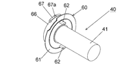
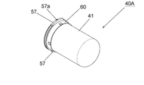
- An exploded perspective view of the filter member 40A is The perspective view of the filter member 40A.
- the cleaner 1 is a cordless and portable cyclone type vacuum cleaner. 1 and 5 define the front-back, up-down, and left-right directions of the cleaner 1 that are orthogonal to each other.
- the front-rear direction is a direction parallel to the rotation shaft (drive shaft) 6a of the motor 6.
- the left-right direction is defined based on the case where the cleaner 1 is viewed from the front.
- the whole including the rotating shaft 6a and its extension line is also referred to as a "central axis".
- FIG. 2 the dust case 3 and the fan cover 20 shown in FIG. 1 are not shown.
- the outer shell of the cleaner 1 is composed of a main body housing 2 and a dust case 3. Both the main body housing 2 and the dust case 3 are, for example, resin molded bodies.
- the dust case 3 is detachably connected and fixed to the front of the main body housing 2.
- the dust case 3 has an intake pipe portion 3a and a swivel chamber 3c.
- the front end opening of the intake pipe portion 3a is an intake port (dust case intake port).
- An extension pipe or a flexible hose (not shown) can be attached to this intake port.
- the intake pipe portion 3a is provided below the swivel chamber 3c.
- the intake pipe portion 3a and the rear end portions of the swivel chamber 3c communicate with each other via the valve portion 3b.
- the valve portion 3b allows the airflow from the intake pipe portion 3a to the swivel chamber 3c to pass, while the airflow from the swivel chamber 3c to the intake pipe portion 3a is blocked.
- the airflow taken into the swivel chamber 3c from the intake pipe portion 3a becomes an air flow that swirls around the swivel shaft in the swivel chamber 3c.
- the swivel axis coincides with the central axis.
- a filter member 40 is detachably attached and accommodated inside the swivel chamber 3c.
- the rear end of the swivel chamber 3c is open.
- a filter member 40 is provided so as to cover this opening.
- the main body housing 2 has a left-right split structure. That is, the main body housing 2 is a body in which the left main body housing 2f and the right main body housing 2g, which are separate parts from each other, are fixed and integrated with each other by screwing or the like. As shown in FIG. 1, the main body housing 2 has an accommodating portion 2a, a handle portion 2b, and a battery pack mounting portion 2c.
- the accommodating portion 2a is a portion corresponding to the front portion of the main body housing 2.
- the accommodating portion 2a accommodates the motor 6, the dust collecting fan 9, the fan guide 10, and the fan cover 20.
- the handle portion 2b is a portion extending rearward from the upper end portion of the accommodating portion 2a. The operator grips the handle portion 2b and handles the cleaner 1.
- An operation panel (switch portion) 5 is provided on the upper surface of the handle portion 2b. Various switches provided on the operation panel 5 can start and stop the cleaner 1 and switch the air volume of the cleaner 1.
- a lighting unit 8 such as an LED that illuminates the front is provided at a position on the handle 2b in front of the operation panel 5.
- the battery pack mounting portion 2c is a portion corresponding to the rear lower portion of the main body housing 2.
- a battery pack 4 that serves as a power source for the cleaner 1 is detachably mounted on the battery pack mounting portion 2c.
- Exhaust ports 2e are provided on both left and right sides of the rear end of the main body housing 2.
- the main body housing 2 has a tubular portion 2h projecting forward at a front end portion.
- the tubular portion 2h is provided with a flange portion 2i that projects inward.
- the flange portion 2i is a plate-shaped portion perpendicular to the front-rear direction.
- the flange portion 2i is provided so as to go around the central axis.
- the inner edge of the flange portion 2i is the opening edge of the intake port (housing intake port) 2d.
- the intake port 2d is a circular through hole centered on the central axis and penetrating in the extending direction of the rotating shaft 6a.
- the intake port 2d is formed so as to straddle the left main body housing 2f and the right main body housing 2g.
- the intake port 2d communicates with the space in the swivel chamber 3c.
- the front of the intake port 2d is covered with the filter member 40.
- the motor 6 is a well-known electric motor with a brush.
- the motor 6 is configured as a unit including a motor case and bearings.
- the motor 6 operates on the power supplied from the battery pack 4.
- the rear end portion of the motor 6 is supported by the main body housing 2 via an elastic body 7 for vibration isolation.
- a dust collecting fan 9 is attached to the rotating shaft 6a of the motor 6.
- the dust collecting fan 9 rotates integrally with the rotating shaft 6a around the rotating shaft 6a.
- the rotating shaft 6a is also the central shaft of the dust collecting fan 9.
- the dust collecting fan 9 is a centrifugal fan.
- the dust collecting fan 9 is housed in an internal space formed by the fan guide 10 and the fan cover 20.
- the outer diameters of the fan guide 10 and the fan cover 20 are larger than the outer diameter of the dust collecting fan 9.
- the outer diameter of the dust collecting fan 9 is larger than the outer diameter of the motor case.
- Both the fan guide 10 and the fan cover 20 are, for example, resin molded bodies.
- the fan guide 10 is fixed to the front surface of the motor 6 by screwing or the like.
- the fan cover 20 is fixed and integrated with the fan guide 10 by claw engagement or the like.
- the fan guide 10 is located behind the dust collecting fan 9.
- the fan guide 10 has a vent (not shown) for passing the air flow generated by the dust collecting fan 9.
- the fan cover 20 has a cylindrical shape centered on the rotating shaft 6a.
- the rear end of the fan cover 20 is open.
- the front end of the fan cover 20 is not open except for the intake port (fan cover intake port) 21. That is, the intake port 21 is provided on the front surface of the fan cover 20.
- the intake port 21 is a circular through hole centered on the central axis and penetrating in the extending direction of the rotating shaft 6a.
- the intake port 21 communicates with the space in the swivel chamber 3c.
- the sealing member 30 seals (closes airtightly) between the main body housing 2 and the fan cover 20. Specifically, the seal member 30 comes into contact with the inside of the intake port 2d in the main body housing 2 and the outside of the intake port 21 in the fan cover 20, so that the main body housing 2 and the fan are between the intake port 2d and the intake port 21. Seal the inside and outside of the cover 20 so that air cannot pass through.
- the seal member 30 also has an anti-vibration function.
- the seal member 30 is an elastic body such as rubber.
- the seal member 30 is formed in an annular shape centered on the central axis.
- the intake port 2d and the intake port 21 communicate with each other through a hole provided in the center of the seal member 30 as a communication passage.
- the seal member 30 is arranged around the intake port 21.
- the outer diameter of the seal member 30 is smaller than the outer diameter of the fan cover 20.
- the outer diameter of the sealing member 30 is larger than the outer diameter of the elastic body 7.
- the filter member 40 includes a breathable filter 41, a first holder 50 as a first component, and a second holder 60 as a second component.
- the filter 41 is, for example, a cloth.
- the filter 41 is formed in a bag shape with an open rear end.
- the filter 41 communicates with the intake port 2d of the main body housing 2 and the intake port 21 of the fan cover 20 through its own opening.
- the first holder 50 and the second holder 60 are made of a material harder than the filter 41. Both the first holder 50 and the second holder 60 are, for example, resin molded bodies.
- the first holder 50 and the second holder 60 are detachably assembled from each other to form a holder for holding the filter 41.
- the filter 41 is sandwiched between the first holder 50 and the second holder 60 in a state where the first holder 50 is assembled to the second holder 60, so that the filter 41 is sandwiched between the first holder 50 and the second holder 60. It is fixed.
- the first holder 50 has a tubular base portion 51 and a columnar portion 54.
- the tubular base 51 has a cylindrical shape centered on the central axis.
- a notch 52 is provided at the rear end of the tubular base 51.
- the cutout portion 52 is an engaging portion that engages with the locking convex portion 64 of the second holder 60.
- a plurality of notches 52 are provided in the circumferential direction (hereinafter, also simply referred to as “circumferential direction”) about the central axis. Specifically, four notches 52 are provided at intervals of 90 degrees in the circumferential direction.
- the rear end portion of the tubular base portion 51 is provided with a convex portion (convex portion) 53 over the entire circumference except for the notch portion 52.
- the convex portion 53 projects from the tubular base portion 51 in the radial direction (hereinafter, also simply referred to as “diameter direction”) about the central axis.
- the columnar portion 54 extends forward from the front end of the tubular base 51.
- the columnar portion 54 is a shape holding portion that holds the filter 41 in a cylindrical shape centered on the swivel axis.
- the second holder 60 has a partition wall portion 61, a first tubular portion 63, and a second tubular portion 66.
- the partition wall portion 61 has a substantially disk shape centered on the central axis and perpendicular to the central axis.
- the partition wall portion 61 forms a rear wall portion of the swivel chamber 3c on the outside of the filter 41.
- the central portion of the partition wall portion 61 is open.
- a pair of knobs 62 are provided on the front surface of the partition wall 61.
- the knob portion 62 is a protrusion that protrudes forward from the partition wall portion 61.
- the knob portion 62 is a portion for an operator to pinch when attaching / detaching the filter member 40 to / from the housing 2.
- the first tubular portion 63 projects rearward from the central opening edge of the partition wall portion 61.
- the first tubular portion 63 has a cylindrical shape centered on the central axis.
- a locking convex portion 64 is provided on the inner peripheral surface of the first tubular portion 63. As shown in FIG. 2 and the like, the locking convex portion 64 engages with the notch 52 of the first holder 50. The engagement between the locking convex portion 64 and the notch portion 52 prevents the first holder 50 from coming off rearward from the second holder 60.
- a plurality of locking convex portions 64 are provided in the circumferential direction. Specifically, four locking convex portions 64 are provided at intervals of 90 degrees in the circumferential direction.
- Notches 69 are provided on both sides of the locking convex portion 64 in the circumferential direction.
- the notch 69 is a portion cut from the rear end of the first tubular portion 63.
- the notch 69 makes it easier for the locking protrusion 64 to fall outward in the radial direction.
- a recess 65 is provided on the inner peripheral surface of the rear end portion of the first tubular portion 63 over the entire circumference. As shown in FIG. 4, the concave portion 65 engages with the convex portion 53 of the first holder 50. The engagement between the concave portion 65 and the convex portion 53 prevents the first holder 50 from coming off from the second holder 60 forward.
- the second tubular portion 66 projects rearward from the partition wall portion 61 on the radial outer side of the first tubular portion 63.
- the second tubular portion 66 has a cylindrical shape centered on the central axis.
- Engagement portions 67 are provided at the upper and lower portions of the rear end portion of the second tubular portion 66, respectively.
- the engaging portion 67 is a portion that protrudes outward in the radial direction from the second tubular portion 66.
- a protrusion 67a is provided at the center of the engaging portion 67 in the circumferential direction.
- the protruding portion 67a projects radially outward from the engaging portion 67. As shown in FIG. 2, the engaging portion 67 is located on the rear side of the wall portion 2k of the main body housing 2.
- the protrusion 67a fits into the recess 2j provided in the main body housing 2.
- the fitting of the protrusion 67a and the recess 2j prevents the second holder 60 from rotating with respect to the main body housing 2.
- the engagement and disengagement of the engaging portion 67 and the main body housing 2 can be performed in a state where the second holder 60 is assembled to the first holder 50. That is, the second holder 60 is detachable from the main body housing 2 in a state of being assembled to the first holder 50.
- a packing 68 as a sealing portion is provided between the first tubular portion 63 and the second tubular portion 66 in the radial direction.
- the packing 68 is an annular elastic body. The packing 68 is pressed against the tubular portion 2h of the main body housing 2 over the entire circumference, and airtightly closes the space between the second holder 60 and the main body housing 2.
- the procedure for assembling the filter member 40 will be described.
- the columnar portion 54 of the first holder 50 is inserted into the opening of the filter 41.
- the inner surface of the opening of the filter 41 comes close to the outer peripheral surface of the tubular base 51 of the first holder 50.
- the columnar portion 54 and the filter 41 are inserted into the central opening of the second holder 60.
- the notch 52 of the first holder 50 and the circumferential position of the locking convex portion 64 of the second holder 60 are aligned with each other and inserted.
- the locking convex portion 64 bends outward in the radial direction, gets over the tubular base portion 51, and fits into the notch portion 52 (engages with the notch portion 52) as shown in FIG.
- the convex portion 53 of the first holder 50 and the concave portion 65 of the second holder 60 are engaged with each other.
- the rear end portion of the filter 41 is sandwiched between the outer peripheral surface of the tubular base portion 51 of the first holder 50 and the inner peripheral surface of the first tubular portion 63 of the second holder 60.
- the filter member 40 is assembled by the above procedure.
- the procedure for attaching the filter member 40 to the main body housing 2 is as follows.
- the filter member 40 is assembled to the main body housing 2 from the front in a state where the second holder 60 is rotated 45 degrees clockwise about the central axis with respect to the rotation position shown in FIG. After that, the filter member 40 is rotated 45 degrees counterclockwise around the central axis.
- the engaging portion 67 of the second holder 60 wraps around behind the wall portion 2k of the main body housing 2, and the protruding portion 67a fits into the recess 2j of the main body housing 2.
- the mounting procedure may be reversed. That is, the filter member 40 may be rotated clockwise by 45 degrees around the central axis to be separated from the main body housing 2 forward.
- the assembly procedure may be reversed. That is, first, the first holder 50 is pulled out rearward from the second holder 60. At this time, by applying a force of a certain amount or more to the rear to the first holder 50, the engagement between the locking convex portion 64 and the notch portion 52 can be released. After pulling out the first holder 50 from the second holder 60, the filter 41 is removed forward from the first holder 50.
- the operation of the cleaner 1 will be described.
- the dust collecting fan 9 is rotated by the driving force of the motor 6.
- the airflow generated by the dust collecting fan 9 is taken into the swirl chamber 3c from the intake pipe portion 3a.
- the airflow becomes a swirling flow in the swirling chamber 3c, passes through the filter member 40, and is taken into the fan cover 20 from the intake ports 2d and 21.
- the airflow is sucked into the inside of the dust collecting fan 9 and discharged to the outside, guided by the fan cover 20, and exits rearward from a vent of the fan guide 10 (not shown).
- the airflow is finally exhausted from the exhaust port 2e to the outside of the main body housing 2.
- Dust that has entered from the intake port 3a together with the air flow is centrifuged in the swirl chamber 3c and collects inside the swirl chamber 3c and outside the filter member 40.
- the dust that has not been centrifuged is collected by the filter 41 of the filter member 40 and collects inside the swirl chamber 3c and outside the filter member 40.
- the filter 41 can be separated from the first holder 50 and the second holder 60, the filter 41 can be easily cleaned. In particular, the filter 41 can be easily washed with water, and the filter 41 can be easily kept clean. Further, since it is not necessary to replace the first holder 50 and the second holder 60 together when the filter 41 is replaced, waste can be reduced.
- the filter member 40 In manufacturing the filter member 40, it is not necessary to fix the filter 41 by sewing it to the holder or the like. Therefore, the filter member 40 can be easily manufactured.
- the filter member 40 and the main body housing 2 are engaged with each other behind the partition wall portion 61, that is, outside the swivel chamber 3c. That is, the configuration of the engaging portion 67 of the second holder 60 and the main body housing 2 engaged with the engaging portion 67 is provided outside the swivel chamber 3c. Therefore, the influence of the engaging structure between the filter member 40 and the main body housing 2 on the swirling flow in the swirling chamber 3c can be suppressed, and the efficiency of centrifugal separation of dust is enhanced.
- cleaner 1A is a cordless and portable non-cyclone vacuum cleaner.
- An intake port (dust case intake port) 3d is provided at the front end of the dust case 3.
- An extension pipe or a flexible hose (not shown) can be attached to the intake port 3d.
- a filter member 40A is detachably provided inside the dust case 3.
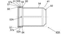
- the first holder 50 of the filter member 40A has a through hole 52A in the tubular base 51.
- the through hole 52A is an engaging portion that engages with the locking convex portion 64 of the second holder 60.
- a plurality of through holes 52A are provided in the circumferential direction. Specifically, four through holes 52A are provided at intervals of 90 degrees in the circumferential direction.
- the through hole 52A replaces the notch 52 of the first embodiment.
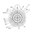
- Engagement portions 57 are provided at the upper and lower portions of the rear end portion of the tubular base portion 51, respectively.
- the engaging portion 57 is a portion that protrudes radially outward from the tubular base portion 51.
- a protrusion 57a is provided at the center of the engaging portion 57 in the circumferential direction.
- the protruding portion 57a projects radially outward from the engaging portion 57.
- the engaging portion 57 and the protruding portion 57a replace the engaging portion 67 and the protruding portion 67a of the first embodiment. That is, in the present embodiment, the engagement structure with the main body housing 2 is provided in the first holder 50.
- the packing 58 as a sealing portion is provided at the rear end portion of the tubular base portion 51.
- the packing 58 is an annular elastic body. The packing 58 is pressed against the front surface of the main body housing 2 over the entire circumference to airtightly close the space between the first holder 50 and the main body housing 2. This embodiment can also exert the same effects as the effects (1) and (2) of the first embodiment.
- the cleaner of the present invention may be a corded type that operates with power supplied from an external AC power source.
- the motor may be a brushless motor.
- 1,1A ... Cleaner (electric vacuum cleaner), 2 ... Main body housing, 2a ... Storage part, 2b ... Handle part, 2c ... Battery pack mounting part, 2d ... Intake port (housing intake port), 2e ... Exhaust port, 2f ... Left housing, 2g ... Right housing, 2h ... Cylindrical part, 2i ... Flange part, 2j ... Recessed part, 2k ... Wall part, 3 ... Dust case, 3a ... Intake pipe part, 3b ... Valve part, 3c ... Swing chamber, 3d ... Intake port (dust case intake port), 4 ... Battery pack, 5 ... Operation panel (switch section), 6 ... Motor, 6a ...
Landscapes
- Engineering & Computer Science (AREA)
- Mechanical Engineering (AREA)
- Filters For Electric Vacuum Cleaners (AREA)
- Filtering Of Dispersed Particles In Gases (AREA)
Priority Applications (2)
| Application Number | Priority Date | Filing Date | Title |
|---|---|---|---|
| CN202080085905.7A CN114828720B (zh) | 2019-12-13 | 2020-11-27 | 清洁器 |
| JP2021563851A JP7388448B2 (ja) | 2019-12-13 | 2020-11-27 | クリーナ |
Applications Claiming Priority (2)
| Application Number | Priority Date | Filing Date | Title |
|---|---|---|---|
| JP2019-225231 | 2019-12-13 | ||
| JP2019225231 | 2019-12-13 |
Publications (1)
| Publication Number | Publication Date |
|---|---|
| WO2021117509A1 true WO2021117509A1 (ja) | 2021-06-17 |
Family
ID=76330189
Family Applications (1)
| Application Number | Title | Priority Date | Filing Date |
|---|---|---|---|
| PCT/JP2020/044272 Ceased WO2021117509A1 (ja) | 2019-12-13 | 2020-11-27 | クリーナ |
Country Status (3)
| Country | Link |
|---|---|
| JP (1) | JP7388448B2 (https=) |
| CN (1) | CN114828720B (https=) |
| WO (1) | WO2021117509A1 (https=) |
Citations (4)
| Publication number | Priority date | Publication date | Assignee | Title |
|---|---|---|---|---|
| JPS61140752U (https=) * | 1985-02-20 | 1986-08-30 | ||
| JPS6395547U (https=) * | 1986-12-05 | 1988-06-20 | ||
| JP2003245232A (ja) * | 2002-02-26 | 2003-09-02 | Toshiba Tec Corp | 電気掃除機 |
| JP2019097952A (ja) * | 2017-12-05 | 2019-06-24 | 小山 勝巳 | ペット用ハンディクリーナー |
Family Cites Families (4)
| Publication number | Priority date | Publication date | Assignee | Title |
|---|---|---|---|---|
| JP2002306384A (ja) * | 2001-04-09 | 2002-10-22 | Makita Corp | クリーナ |
| JP5190299B2 (ja) * | 2008-05-24 | 2013-04-24 | ツインバード工業株式会社 | サイクロン式掃除機 |
| JP5651523B2 (ja) * | 2011-04-21 | 2015-01-14 | 株式会社マキタ | クリーナ |
| CN108078485A (zh) * | 2017-11-30 | 2018-05-29 | 江苏美的清洁电器股份有限公司 | 甩灰组件、尘杯和吸尘器 |
-
2020
- 2020-11-27 JP JP2021563851A patent/JP7388448B2/ja active Active
- 2020-11-27 CN CN202080085905.7A patent/CN114828720B/zh active Active
- 2020-11-27 WO PCT/JP2020/044272 patent/WO2021117509A1/ja not_active Ceased
Patent Citations (4)
| Publication number | Priority date | Publication date | Assignee | Title |
|---|---|---|---|---|
| JPS61140752U (https=) * | 1985-02-20 | 1986-08-30 | ||
| JPS6395547U (https=) * | 1986-12-05 | 1988-06-20 | ||
| JP2003245232A (ja) * | 2002-02-26 | 2003-09-02 | Toshiba Tec Corp | 電気掃除機 |
| JP2019097952A (ja) * | 2017-12-05 | 2019-06-24 | 小山 勝巳 | ペット用ハンディクリーナー |
Also Published As
| Publication number | Publication date |
|---|---|
| JP7388448B2 (ja) | 2023-11-29 |
| JPWO2021117509A1 (https=) | 2021-06-17 |
| CN114828720B (zh) | 2023-09-15 |
| CN114828720A (zh) | 2022-07-29 |
Similar Documents
| Publication | Publication Date | Title |
|---|---|---|
| JP2009131329A (ja) | 電気掃除機 | |
| JP7103373B2 (ja) | 集塵機 | |
| KR20100114067A (ko) | 전기 진공 청소기 | |
| JP7315025B2 (ja) | クリーナ | |
| JP7514668B2 (ja) | クリーナ | |
| CN117837969A (zh) | 集尘机 | |
| JP7388448B2 (ja) | クリーナ | |
| JP7842525B2 (ja) | クリーナ | |
| KR20230120337A (ko) | 청소기 | |
| JP2009207555A (ja) | 電気掃除機 | |
| JP6334913B2 (ja) | 電気掃除機 | |
| JP7012420B2 (ja) | 電気掃除機 | |
| JP6216218B2 (ja) | 電気掃除機 | |
| US20260069095A1 (en) | Cleaner | |
| CN112294177A (zh) | 电动吸尘器的吸入口体以及电动吸尘器 | |
| WO2023127926A1 (ja) | 作業機 | |
| JP6254436B2 (ja) | 電気掃除機 | |
| JP7526488B2 (ja) | 電気掃除機の吸込口体、及び電気掃除機 | |
| JP2014023860A (ja) | 電気掃除機 | |
| JP6705263B2 (ja) | 吸込具 | |
| JP2004298495A (ja) | 電気掃除機 | |
| JP2021029599A (ja) | サイクロンユニット及びクリーナ | |
| JP4945665B2 (ja) | 電気掃除機 | |
| KR0177072B1 (ko) | 먼지봉투가 부착된 진공청소기의 분리형 커버 | |
| JP2024033910A (ja) | 作業機 |
Legal Events
| Date | Code | Title | Description |
|---|---|---|---|
| 121 | Ep: the epo has been informed by wipo that ep was designated in this application |
Ref document number: 20900469 Country of ref document: EP Kind code of ref document: A1 |
|
| ENP | Entry into the national phase |
Ref document number: 2021563851 Country of ref document: JP Kind code of ref document: A |
|
| NENP | Non-entry into the national phase |
Ref country code: DE |
|
| 122 | Ep: pct application non-entry in european phase |
Ref document number: 20900469 Country of ref document: EP Kind code of ref document: A1 |