WO2021111778A1 - 伝熱装置 - Google Patents
伝熱装置 Download PDFInfo
- Publication number
- WO2021111778A1 WO2021111778A1 PCT/JP2020/040599 JP2020040599W WO2021111778A1 WO 2021111778 A1 WO2021111778 A1 WO 2021111778A1 JP 2020040599 W JP2020040599 W JP 2020040599W WO 2021111778 A1 WO2021111778 A1 WO 2021111778A1
- Authority
- WO
- WIPO (PCT)
- Prior art keywords
- heat transfer
- contact area
- external force
- magnitude
- threshold value
- Prior art date
- Legal status (The legal status is an assumption and is not a legal conclusion. Google has not performed a legal analysis and makes no representation as to the accuracy of the status listed.)
- Ceased
Links
Images





Classifications
-
- F—MECHANICAL ENGINEERING; LIGHTING; HEATING; WEAPONS; BLASTING
- F28—HEAT EXCHANGE IN GENERAL
- F28D—HEAT-EXCHANGE APPARATUS, NOT PROVIDED FOR IN ANOTHER SUBCLASS, IN WHICH THE HEAT-EXCHANGE MEDIA DO NOT COME INTO DIRECT CONTACT
- F28D7/00—Heat-exchange apparatus having stationary tubular conduit assemblies for both heat-exchange media, the media being in contact with different sides of a conduit wall
-
- F—MECHANICAL ENGINEERING; LIGHTING; HEATING; WEAPONS; BLASTING
- F28—HEAT EXCHANGE IN GENERAL
- F28F—DETAILS OF HEAT-EXCHANGE AND HEAT-TRANSFER APPARATUS, OF GENERAL APPLICATION
- F28F13/00—Arrangements for modifying heat-transfer, e.g. increasing, decreasing
-
- F—MECHANICAL ENGINEERING; LIGHTING; HEATING; WEAPONS; BLASTING
- F25—REFRIGERATION OR COOLING; COMBINED HEATING AND REFRIGERATION SYSTEMS; HEAT PUMP SYSTEMS; MANUFACTURE OR STORAGE OF ICE; LIQUEFACTION SOLIDIFICATION OF GASES
- F25B—REFRIGERATION MACHINES, PLANTS OR SYSTEMS; COMBINED HEATING AND REFRIGERATION SYSTEMS; HEAT PUMP SYSTEMS
- F25B23/00—Machines, plants or systems, with a single mode of operation not covered by groups F25B1/00 - F25B21/00, e.g. using selective radiation effect
-
- F—MECHANICAL ENGINEERING; LIGHTING; HEATING; WEAPONS; BLASTING
- F28—HEAT EXCHANGE IN GENERAL
- F28F—DETAILS OF HEAT-EXCHANGE AND HEAT-TRANSFER APPARATUS, OF GENERAL APPLICATION
- F28F13/00—Arrangements for modifying heat-transfer, e.g. increasing, decreasing
- F28F2013/005—Thermal joints
- F28F2013/006—Heat conductive materials
-
- F—MECHANICAL ENGINEERING; LIGHTING; HEATING; WEAPONS; BLASTING
- F28—HEAT EXCHANGE IN GENERAL
- F28F—DETAILS OF HEAT-EXCHANGE AND HEAT-TRANSFER APPARATUS, OF GENERAL APPLICATION
- F28F13/00—Arrangements for modifying heat-transfer, e.g. increasing, decreasing
- F28F2013/005—Thermal joints
- F28F2013/008—Variable conductance materials; Thermal switches
Definitions
- This disclosure relates to a heat transfer device.
- Patent Document 1 describes that a regenerator of a cooling system is composed of a plurality of solid cooling materials capable of exhibiting a thermoelastic effect.
- the cooling system includes a heat sink, a freezing space, and a regenerator.
- the solid cooling material is, for example, a shape memory alloy and is molded into a shape such as a wire.
- Patent Document 2 describes that a large number of heat strain materials are used in each of the cooling and heating parts of the cooling and heating module that cools and heats air.
- the thermal strain material is composed of, for example, a shape memory alloy.
- the heat strain material is formed in the form of wires extending vertically.
- Patent Document 3 describes a heat pump that utilizes a shape memory alloy.
- the belt is formed of shape memory alloy.
- a first member containing a first solid material exhibiting a thermoelastic effect A first heat transfer body in which the first contact area, which is the contact area between the first member, varies.
- the first contact area when the magnitude of the first external force applied to the first member is smaller than the first threshold value which is the threshold value of the endothermic reaction and the exothermic reaction in the thermoelastic effect of the first solid material is the first.
- the magnitude of the external force is larger than the first contact area when it is equal to or greater than the first threshold value.
- the second contact area when the magnitude of the first external force is smaller than the first threshold value is smaller than the second contact area when the magnitude of the first external force is equal to or greater than the first threshold value.
- heat transfer by heat conduction can be performed by changing the contact area between a member containing a solid material exhibiting a thermoelastic effect and a heat transfer body.
- a heat transfer device By using a solid material exhibiting a thermoelastic effect to mediate heat transfer from a specific heat transfer body to another heat transfer body, a heat transfer device can be constructed without using fluorocarbon, hydrofluorocarbon, or the like. Can be considered. Such a heat transfer device is advantageous from the viewpoint of preventing ozone layer depletion and preventing global warming. For example, when an external force is applied to a solid material exhibiting a thermoelastic effect to cause a phase transition, heat of transition is generated. If the heat absorption and heat generation associated with such a thermoelastic effect can be effectively used in the heat transfer device, the value of the heat transfer device can be increased. In addition, if a solid material exhibiting a thermoelastic effect and a plurality of heat transfer bodies can be brought into contact with each other to generate heat transfer by heat conduction, the characteristics of the heat transfer device can be easily enhanced.
- the heat transfer device is A first member containing a first solid material exhibiting a thermoelastic effect, A first heat transfer body in which the first contact area, which is the contact area between the first member, varies. A second heat transfer body having a variable second contact area, which is a contact area between the first member, is provided.
- the first contact area when the magnitude of the first external force applied to the first member is smaller than the first threshold value which is the threshold value of the endothermic reaction and the exothermic reaction in the thermoelastic effect of the first solid material is the first.
- the magnitude of the external force is larger than the first contact area when it is equal to or greater than the first threshold value.
- the second contact area when the magnitude of the first external force is smaller than the first threshold value is smaller than the second contact area when the magnitude of the first external force is equal to or greater than the first threshold value.
- the first contact area when the magnitude of the first external force is smaller than the first threshold value, the first contact area is larger than the second contact area.
- the first contact area may be equal to or smaller than the second contact area.
- heat transfer by heat conduction tends to be active between the first heat transfer body and the first member.
- heat transfer due to heat conduction tends to be active between the second heat transfer body and the first member.
- the first solid material when the magnitude of the first external force is smaller than the first threshold value, the first solid material is the first.
- the first solid material may have a second phase different from the first phase when it has a phase and the magnitude of the first external force is equal to or greater than the first threshold value.
- the phase transition of the first solid material can be promoted by changing the magnitude of the first external force according to the first threshold value, and the thermoelastic effect can be exhibited.
- the first member may be a first coil spring.
- the first contact area and the second contact area can be adjusted by adjusting the first external force around the axis of the first coil spring.
- a pair of cross sections perpendicular to the axis of the wire rod forming the first coil spring form the first inner circumference and the first outer circumference. It may contain parallel line segments. According to the sixth aspect, it is easy to increase the first contact area and the second contact area.
- the heat transfer device according to any one of the first to sixth aspects further includes a first drive mechanism for periodically increasing and decreasing the first external force. You may.
- the first external force can be periodically increased and decreased by the first driving mechanism.
- the fourth contact area which is smaller than the third contact area when it is equal to or more than the second threshold value and the magnitude of the second external force is smaller than the second threshold value, has the magnitude of the second external force. It may be larger than the fourth contact area when it is equal to or more than the second threshold value.
- the contact area between the third heat transfer body and the second member has a second external force larger than that when the second external force is smaller than the second threshold value. Greater when above the threshold. Therefore, when the magnitude of the second external force is equal to or greater than the second threshold value, heat is likely to be transferred between the third heat transfer body and the second member by heat conduction.
- the contact area between the second heat transfer body and the second member is when the magnitude of the second external force is smaller than the second threshold value as compared with the case where the magnitude of the second external force is equal to or larger than the second threshold value. Greater than. Therefore, when the magnitude of the second external force is smaller than the second threshold value, heat is easily transferred between the second heat transfer body and the second member by heat conduction.
- a plurality of members including a solid material exhibiting a thermoelastic effect and three or more heat transfer bodies are connected in series to increase the temperature difference between the plurality of heat transfer bodies. Cheap.
- the heat transfer device is A second member containing a second solid material exhibiting a thermoelastic effect
- the fourth contact area which is the contact area between the second member and the second heat transfer body, fluctuates due to the fluctuation of the magnitude of the second external force applied to the second member.
- the magnitude of the second external force is smaller than the second threshold value which is the threshold value of the heat absorption reaction and the exothermic reaction in the thermoelastic effect of the second solid material
- the magnitude of the second external force is the magnitude of the second external force.
- the fourth contact area which is larger than the third contact area when the second threshold value or more and the magnitude of the second external force is smaller than the second threshold value, has the magnitude of the second external force. It may be smaller than the fourth contact area when it is equal to or more than the second threshold value.
- the contact area between the third heat transfer body and the second member has a second external force larger than that when the second external force is equal to or larger than the second threshold value. Greater when less than 2 thresholds. Therefore, when the magnitude of the second external force is smaller than the second threshold value, heat is easily transferred between the third heat transfer body and the second member by heat conduction.
- the contact area between the second heat transfer body and the second member is when the magnitude of the second external force is equal to or greater than the second threshold value as compared with the case where the magnitude of the second external force is smaller than the second threshold value. Greater than.
- a plurality of members including a solid material exhibiting a thermoelastic effect and three or more heat transfer bodies can be connected in series, and the temperature difference between the plurality of heat transfer bodies is increased.
- the third contact area is larger than the fourth contact area.
- the third contact area may be equal to or smaller than the fourth contact area.
- heat transfer by heat conduction tends to be active between the third heat transfer body and the second member.
- heat transfer due to heat conduction tends to be active between the second heat transfer body and the second member.
- the second member has a second inner circumference and a second outer circumference
- the said One of the second heat transfer body and the third heat transfer body is arranged so as to face the second inner circumference
- the other of the second heat transfer body and the third heat transfer body faces the second outer circumference.
- the third contact area and the third contact area are adjusted by adjusting the second external force so that the second inner circumference or the second outer circumference of the second member is brought closer to the second heat transfer body or the third heat transfer body.
- the fourth contact area can be adjusted.
- the second member may be a second coil spring.
- the third contact area and the fourth contact area can be adjusted by adjusting the second external force around the axis of the second coil spring.
- the cross section of the wire rod forming the second coil spring is formed in the second aspect. It may include a pair of parallel line segments forming the circumference and the second outer circumference. According to the fifteenth aspect, it is easy to increase the third contact area and the fourth contact area.
- the heat transfer device according to any one of the 8th to 15th aspects further includes a second drive mechanism for periodically increasing and decreasing the second external force. You may.
- the second external force can be periodically increased and decreased by the second driving mechanism.
- FIGS. 1 and 2 show an example of the heat transfer device of the present disclosure.
- the heat transfer device includes, for example, a main body 10a.
- the main body 10a includes a first member 11, a first heat transfer body 21, and a second heat transfer body 22.
- the first member 11 contains a first solid material that exhibits a thermoelastic effect.
- the first contact area which is the contact area between the first heat transfer body 21 and the first member 11, varies.
- the second contact area which is the contact area between the second heat transfer body 22 and the first member 11, varies.
- the first contact area when the magnitude of the first external force applied to the first member 11 is smaller than the first threshold value is larger than the first contact area when the magnitude of the first external force is equal to or greater than the first threshold value. Is also big. Therefore, when the magnitude of the first external force is smaller than the first threshold value, heat is easily transferred between the first heat transfer body 21 and the first member 11 by heat conduction.
- the second contact area when the magnitude of the first external force is smaller than the first threshold value is smaller than the second contact area when the magnitude of the first external force is equal to or larger than the first threshold value.
- the first threshold is the threshold of the endothermic reaction and the exothermic reaction in the thermoelastic effect of the first solid material.
- the first contact area and the second contact area can be changed by adjusting the first external force, and the first member 11 is the first heat transfer. It can mediate heat transport between the body 21 and the second heat transfer body 22.
- the thermoelastic effect can be exerted in the first solid material, and the transition heat accompanying the thermoelastic effect can be utilized in the heat transfer device.
- the first contact area is larger than the second contact area.
- heat transfer due to heat conduction tends to be active between the first heat transfer body 21 and the first member 11.
- the first contact area is equal to or less than the second contact area.
- the first contact area may be zero and the second contact area may be zero due to the fluctuation of the magnitude of the first external force.
- the first member 11 and the first heat transfer body 21 may not be in complete contact with each other, and the first member 11 and the second heat transfer body 22 may be in a state where they are not completely in contact with each other. May not be in complete contact with.
- the first solid material when the magnitude of the first external force is smaller than the first threshold value, the first solid material has the first phase, and when the magnitude of the first external force is equal to or larger than the first threshold value, The first solid material has a second phase that is different from the first phase.
- the second phase is, for example, a phase having a standard enthalpy of formation different from the standard enthalpy of formation of the first phase.
- the first solid material is not limited to a specific material as long as it exhibits a thermoelastic effect.
- the first solid material may be, for example, a shape memory alloy, a thermoelastic polymer, or a plastic crystal.
- the shape memory alloy is, for example, a nickel-titanium alloy, a copper-aluminum-nickel alloy, or a copper-zinc-aluminum alloy.
- the thermoelastic polymer may be, for example, a block copolymer of polyethylene terephthalate (PET) and polyethylene oxide (PEO).
- PET polyethylene terephthalate
- PEO polyethylene oxide
- the thermoelastic polymer may be, for example, a block copolymer containing polystyrene and poly (1,4-butadiene).
- the thermoelastic polymer may be, for example, an ABA triblock copolymer composed of poly (2-methyl-2-oxazoline) and polytetrahydrofuran.
- the thermoelastic polymer may be, for example, nylon or natural rubber.
- Plastic crystals include, for example, neopentyl glycol (NPG), pentaglycerin (PG), pentaerythritol (PE), 2-amino-2-methyl-1,3-propanediol (AMP), tris (hydroxymethyl) aminomethane (TRIS), 2-methyl-2-nitro-1-propanol (MNP) and 2-nitro-2-methyl-1,3-propanediol (NMP).
- the first threshold is, for example, about 140 MPa.
- the first threshold value may be defined as a specific value, or may be defined as a set of values between a lower limit value and an upper limit value larger than the lower limit value.
- FIG. 3 is a perspective view showing the first member 11.
- the first member 11 has, for example, a first inner circumference 11u and a first outer circumference 11s.
- the second heat transfer body 22 is arranged to face the first inner circumference 11u
- the first heat transfer body 21 is arranged to face the first outer circumference 11s. ..
- the first heat transfer body 21 may be arranged so as to face the first inner circumference 11u
- the second heat transfer body 22 may be arranged to face the first outer peripheral 11s.
- the first contact area is adjusted by adjusting the first external force so that the first inner circumference 11u or the first outer circumference 11s is brought closer to the first heat transfer body 21 or the second heat transfer body 22.
- the second contact area can be adjusted.
- the first heat transfer body 21 is, for example, an annular component arranged around the first member 11.
- the first heat transfer body 21 is formed of, for example, a metal material such as a metal or an alloy.
- the first heat transfer body 21 may be a hollow part or a solid part. When the first heat transfer body 21 is a hollow component, the inside of the first heat transfer body 21 may be filled with a liquid or powdery substance, or a fluid may flow.
- the second heat transfer body 22 is, for example, a columnar or tubular part, and the first member 11 is arranged around the second heat transfer body 22.
- the second heat transfer body 22 is formed of, for example, a metal material such as a metal or an alloy.
- the second heat transfer body 22 may be a hollow part or a solid part. When the second heat transfer body 22 is a hollow component, the inside of the second heat transfer body 22 may be filled with a liquid or powdery substance, or a fluid may flow.
- the temperature of the first heat transfer body 21 is kept higher than the temperature of the second heat transfer body 22.
- the first member 11 is, for example, a first coil spring.
- the first contact area and the second contact area are adjusted by adjusting the first external force so as to twist the first coil spring 11 or to eliminate the twist of the first coil spring 11. Can be adjusted.
- the first contact area and the second contact area can be adjusted by adjusting the first external force around the axis of the first coil spring.
- the first member 11 may be a tubular component having a slit extending in the axial direction.
- the cross section perpendicular to the axis of the wire rod forming the first coil spring 11 includes, for example, a pair of parallel line segments forming the first inner circumference 11u and the first outer circumference 11s. .. According to such a configuration, it is easy to increase the first contact area and the second contact area.
- the cross section of the wire rod forming the first coil spring 11 perpendicular to the axis may be rectangular. For example, a gap is formed between the surface of the second heat transfer body 22 facing the first inner circumference 11u and the surface of the first heat transfer body 21 facing the first outer circumference 11s.
- the dimension of this gap in the direction perpendicular to the axis of the first coil spring 11 is larger than the distance between the pair of parallel line segments forming the first inner circumference 11u and the first outer circumference 11s.
- the first coil spring 11 is arranged in this gap.
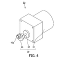
- the main body 10a further includes, for example, a pin 35a, a rotating member 36, and a holding member 40a.
- the rotating member 36 is, for example, an annular member.
- the rotating member 36 is rotatably arranged around the axis of the first member 11 in contact with the first heat transfer body 21 in the axial direction of the first member 11.
- the pin 35a is attached to the rotating member 36, and a part of the pin 35a projects outward in the axial direction of the first member 11.
- One end of the first member 11 is fixed to the rotating member 36.
- the holding member 40a is, for example, an annular member.
- the holding member 40a is arranged in contact with the first heat transfer body 21 in the axial direction of the first member 11, for example.
- the first heat transfer body 21 is arranged between the rotating member 36 and the holding member 40a in the axial direction of the first member 11.
- the end portion of the first coil spring 11 is housed inside the holding member 40a, and the end portion thereof is fixed to the holding member 40a.
- the rotating member 36 is rotated toward the initial position of the pin 35a in the direction indicated by the arrow B. With this rotation, the first external force becomes smaller than the first threshold value, and the second phase shifts to the first phase in the first solid material.
- the temperature of the first member 11 is further lowered by the heat of transition accompanying the phase transition from the second phase to the first phase.
- the pin 35a is returned to the initial position, most of the outer peripheral 11s of the first member 11 comes into contact with the first heat transfer body 21. At this time, the temperature of the first member 11 begins to rise due to the heat conduction between the first member 11 and the first heat transfer body 21.
- the first drive mechanism 30 includes, for example, a motor 31, a rod 32, and a cam 33.
- the rod 32 is connected to the motor 31, and the cam 33 is fixed to the tip of the rod 32.
- the cam 33 is, for example, an elliptical columnar component, and is in contact with, for example, the side surface of the pin 35a.
- the power generated by the motor 31 causes the rod 32 and the cam 33 to rotate around the axis of the rod 32.
- the pin 35a slides on the side surface of the cam 33.
- the motion of rotating the rotating member 36 in the direction indicated by the arrow A and the motion of rotating the rotating member 36 in the direction indicated by the arrow B in FIG. 1 are periodically repeated.
- the heat transfer device 50 can be changed from various viewpoints.
- the heat transfer device 50 may be modified to include the main body 10b shown in FIG. 6 instead of the main body 10a.
- the main body 10b is configured in the same manner as the main body 10a except for a portion to be described in particular.
- the same reference numerals are given to the components of the main body 10b that are the same as or corresponding to the components of the main body 10a, and detailed description thereof will be omitted.
- the description of the body 10a also applies to the body 10b, as long as there is no technical contradiction.
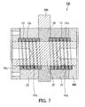
- the main body 10b the first member 11 and the second member 12 and the first heat transfer body 21, the second heat transfer body 22, and the third heat transfer body 23 are connected in series, for example, the first heat transfer body. It is easy to increase the temperature difference between the heat body 21, the second heat transfer body 22, and the third heat transfer body 23.
- the third contact area is equal to or less than the fourth contact area.
- the third contact area is larger than the fourth contact area.
- the third contact area does not have to be less than or equal to the fourth contact area in all periods when the magnitude of the second external force is smaller than the second threshold value.
- the contact area is equal to or less than the fourth contact area.
- the third contact area does not have to be larger than the fourth contact area during all periods when the magnitude of the second external force is equal to or greater than the second threshold value. For example, when the magnitude of the second external force is maximum, the third contact area does not need to be larger. Is larger than the fourth contact area.
- the third contact area may be zero and the fourth contact area may be zero due to the fluctuation of the magnitude of the second external force.
- the second member 12 and the second heat transfer body 22 may not be in complete contact with each other, and the second member 12 and the third heat transfer body 23 may be in a state where they are not completely in contact with each other. May not be in complete contact with.
- the second solid material 12 when the magnitude of the second external force is smaller than the second threshold value, the second solid material 12 has the third phase, and when the magnitude of the second external force is equal to or larger than the second threshold value, the second solid material 12 has a third phase.
- the 2 solid material 12 may have a fourth phase different from the third phase. According to such a configuration, the phase transition of the second solid material can be promoted by changing the magnitude of the second external force according to the second threshold value, and the thermoelastic effect can be exhibited.
- the fourth phase is, for example, a phase having a standard enthalpy of formation different from the standard enthalpy of formation of the third phase.
- the second solid material is not limited to a specific material as long as it exhibits a thermoelastic effect.
- the second solid material can be, for example, the material shown as an example of the first solid material.
- the second solid material may be the same type of material as the first solid material, or may be a different type of material from the first solid material.
- the second threshold is, for example, about 140 MPa.
- the second threshold value may be defined as a specific value, or may be defined as a set of values between a lower limit value and an upper limit value larger than the lower limit value.
- the second member 12 has a second inner circumference 12u and a second outer circumference 12s.
- the second heat transfer body 22 may be arranged so as to face the second inner circumference 12u
- the third heat transfer body 23 may be arranged so as to face the second outer circumference 12s.
- the third heat transfer body 23 may be arranged so as to face the second inner circumference 12u
- the second heat transfer body 22 may be arranged to face the first outer peripheral 11s.
- the third contact area is adjusted by adjusting the second external force so that the second inner circumference 12u or the second outer circumference 12s is brought closer to the second heat transfer body 22 or the third heat transfer body 23.
- the fourth contact area can be adjusted.
- the second member 12 may be a tubular component having a slit extending in the axial direction.
- the second member 12 is a second coil spring.
- the third contact area and the fourth contact area can be adjusted by adjusting the second external force so as to twist the second coil spring 12 or to eliminate the twist of the second coil spring 12. Can be adjusted.
- the third contact area and the fourth contact area can be adjusted by applying a second external force around the axis of the second coil spring.
- the cross section perpendicular to the axis of the wire rod forming the second coil spring 12 includes, for example, a pair of parallel line segments forming the second inner circumference 12u and the second outer circumference 12s. According to such a configuration, it is easy to increase the third contact area and the fourth contact area.
- the cross section of the wire rod forming the second coil spring 12 perpendicular to the axis may be rectangular. For example, a gap is formed between the surface of the second heat transfer body 22 facing the second inner circumference 12u and the surface of the third heat transfer body 23 facing the second outer circumference 12s.
- the dimension of this gap in the direction perpendicular to the axis of the second coil spring 12 is larger than the distance between the pair of parallel line segments forming the second inner circumference 12u and the second outer circumference 12s.
- the second coil spring 12 is arranged in this gap.
- the main body 10b further includes, for example, a pin 35b, a rotating member 36, a first holding member 40b, and a second holding member 40c.
- the pin 35b is attached to the rotating member 36, and a part of the pin 35b projects outward in a direction perpendicular to the axis of the first member 11.
- One ends of the first member 11 and the second member 12 are fixed to the rotating member 36, respectively.
- Each of the first holding member 40b and the second holding member 40c is, for example, an annular member.
- the first holding member 40b is arranged in contact with the first heat transfer body 21 in the axial direction of the first member 11, for example.
- the second holding member 40c is arranged in contact with the third heat transfer body 23 in the axial direction of the second member 12, for example.
- the first heat transfer body 21 is arranged between the rotating member 36 and the first holding member 40b in the axial direction of the first member 11, and the rotating member 36 and the second member 12 are arranged in the axial direction of the second member 12.
- the first heat transfer body 21 is arranged between the two holding members 40c.
- the end of the first coil spring 11 is housed inside the first holding member 40b, and the end thereof is fixed to the holding member 40b.
- the end of the second coil spring 12 is housed inside the second holding member 40c, and the end thereof is fixed to the holding member 40c.
- the second heat transfer body 22 is, for example, a columnar or tubular part, and the first member 11, the second member 12, and the rotation around the second heat transfer body 22.
- the member 36 is arranged.
- the second heat transfer body 22 is formed of, for example, a metal material such as a metal or an alloy.
- the second heat transfer body 22 may be a hollow part or a solid part. When the second heat transfer body 22 is a hollow component, the inside of the second heat transfer body 22 may be filled with a liquid or powdery substance, or a fluid may flow.
- the second member 12 is deformed so as to be pressed against the third heat transfer body 23, and most of the outer circumference 12s of the second member 12 comes into contact with the third heat transfer body 23, and the inside of the second member 12 Most of the circumference 12s is separated from the second heat transfer body 22.
- the temperature of the second member 12 drops due to heat conduction between the second member 12 and the third heat transfer body 23.
- the rotating member 36 is rotated in the opposite direction so as to return the pin 35b to the initial position.
- the second external force becomes smaller than the second threshold value, and the fourth phase shifts to the third phase in the second solid material.
- the temperature of the second member 12 is further lowered by the heat of transition accompanying the phase transition from the fourth phase to the third phase.
- the main body 10b may further include a second drive mechanism in addition to the first drive mechanism 30, for example.
- the second drive mechanism is a mechanism that periodically increases and decreases the second external force.
- the first drive mechanism 30 may also serve as the second drive mechanism.
- the cam 33 of the first drive mechanism 30 is brought into contact with the side surface of the pin 35b.
- the power generated by the motor 31 causes the rod 32 and the cam 33 to rotate around the axis of the rod 32.
- the pin 35b slides on the side surface of the cam 33.
- the second drive mechanism may be configured as a mechanism independent of the first drive mechanism 30.
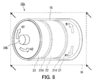
- the main body 10b may be changed as shown in the main body 10c shown in FIGS. 8 to 10.
- the main body 10c is configured in the same manner as the main body 10b except for a portion to be described in particular.
- the same components as or corresponding to the components of the main body 10b are designated by the same reference numerals, and detailed description thereof will be omitted.
- the description of the main bodies 10a and 10b also applies to the main body 10c, unless technically inconsistent.
- the main body 10c has the second member 12 and the third member 12 in addition to the first member 11, the first heat transfer body 21, and the second heat transfer body 22, similarly to the main body 10b. It includes a heat transfer body 23.
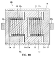
- 9 and 10 are cross-sectional views of the main body 10c along the plane IX shown in FIG.
- FIG. 9 shows the state of the main body 10c when the magnitude of the first external force is smaller than the first threshold value and the magnitude of the second external force is smaller than the second threshold value.
- FIG. 10 shows the state of the main body 10c when the magnitude of the first external force is equal to or greater than the first threshold value and the magnitude of the second external force is equal to or greater than the second threshold value.
- the main body 10c is configured so that the third contact area when the magnitude of the second external force is smaller than the second threshold value is larger than the third contact area when the magnitude of the second external force is greater than or equal to the second threshold value. Has been done.
- the main body 10c so that the fourth contact area when the magnitude of the second external force is smaller than the second threshold value is smaller than the fourth contact area when the magnitude of the second external force is greater than or equal to the second threshold value. is configured. According to such a configuration, when the magnitude of the second external force is smaller than the second threshold value, heat is easily transferred between the third heat transfer body 23 and the second member 12 by heat conduction. Further, when the magnitude of the second external force is equal to or larger than the second threshold value, heat is easily transferred between the second heat transfer body 22 and the second member 12 by heat conduction.
- the main body 10c may be further configured as follows. For example, in the main body 10c, when the magnitude of the second external force is smaller than the second threshold value, the third contact area is larger than the fourth contact area. As a result, when the magnitude of the second external force is smaller than the second threshold value, heat transfer due to heat conduction tends to be active between the third heat transfer body 23 and the second member 12. In addition, when the magnitude of the second external force is equal to or greater than the second threshold value, the third contact area is equal to or less than the fourth contact area. When the magnitude of the second external force is equal to or greater than the second threshold value, heat transfer due to heat conduction tends to be active between the second heat transfer body 22 and the second member 12.
- the main body 10c includes a first rotating member 36a and a second rotating member 36b.
- the first rotating member 36a is fixed to the first heat transfer body 21, and the second rotating member 36b is fixed to the third heat transfer body 23.
- the first heat transfer body 21 is formed in a rotating body shape including, for example, a base portion and a protruding portion protruding from the base portion.
- the second heat transfer body 22 is formed in a rotating body shape including, for example, a tubular portion having a bottom portion and a protruding portion protruding from the bottom portion of the tubular portion.
- the third heat transfer body 23 is formed in a rotating body shape including a tubular portion having a bottom portion.
- the axis of the first heat transfer body 21, the axis of the second heat transfer body 22, and the axis of the third heat transfer body 23 extend on the same straight line, for example.
- One end of the first member 11 is fixed to the base of the first heat transfer body 21.
- the other end of the first member 11 is fixed to the inner surface of the bottom portion of the tubular portion of the second heat transfer body 22.
- One end of the second member 12 is fixed to the inner surface of the bottom of the third heat transfer body 23.
- the other end of the second member 12 is fixed to the outer surface of the bottom portion of the tubular portion of the second heat transfer body 22.
- the first member 11 is arranged around the protruding portion of the first heat transfer body 21, and is housed inside the tubular portion of the first heat transfer body 21.
- the second member 12 is arranged around the protruding portion of the second heat transfer body 21, and is housed inside the tubular portion of the third heat transfer body 23.
- the main body 10c further includes a heat insulating material 21d, a heat insulating material 22d, a heat insulating material 22k, and a heat insulating material 23k.
- the thermal conductivity of these heat insulating materials is lower than, for example, the thermal conductivity of the first member 11 and the second member 12.
- the heat insulating material 21d is annular and covers the base portion at the boundary between the base portion and the protruding portion in the first heat transfer body 21.
- the heat insulating material 22d is annular and covers the outer surface of the bottom portion of the second heat transfer body 22 at the boundary between the bottom portion and the protruding portion of the tubular portion.
- the heat insulating material 22k covers the inner surface of the bottom portion of the tubular portion in the second heat transfer body 22.
- the heat insulating material 23k covers the inner surface of the bottom portion of the tubular portion in the third heat transfer body 23.
- the main body 10c further includes, for example, a cylinder 15.
- the first member 11, the second member 12, the first heat transfer body 21, the second heat transfer body 22, and the third heat transfer body 23 are housed inside the cylinder 15.
- the inner surface of the cylinder 15 is made of a heat insulating material.
- the thermal conductivity of this heat insulating material is, for example, lower than the thermal conductivity of the first member 11 and the second member 12.
- the axis of the cylinder 15 extends on the same straight line as, for example, the axis of the first heat transfer body 21, the axis of the second heat transfer body 22, and the axis of the third heat transfer body 23.
- the first rotating member 36a when the first rotating member 36a is rotated in the direction of the arrow A1 in FIG. 8 by a predetermined drive mechanism (not shown), the first external force becomes large and the first external force becomes equal to or higher than the first threshold value. After that, the first rotating member 36a is rotated in the direction of the arrow B1 in FIG. 8 by the driving mechanism, so that the first external force becomes small and the first external force becomes smaller than the first threshold value.
- the second external force is increased by rotating the second rotating member 36b in the direction of the arrow A2 in FIG. 8 by a predetermined drive mechanism (not shown). After that, the second rotating member 36b is rotated in the direction of the arrow B2 in FIG. 8 by the driving mechanism, so that the second external force is reduced.
Landscapes
- Engineering & Computer Science (AREA)
- Physics & Mathematics (AREA)
- Thermal Sciences (AREA)
- Mechanical Engineering (AREA)
- General Engineering & Computer Science (AREA)
- Thermotherapy And Cooling Therapy Devices (AREA)
- Cooling Or The Like Of Semiconductors Or Solid State Devices (AREA)
- Steering Controls (AREA)
Priority Applications (3)
| Application Number | Priority Date | Filing Date | Title |
|---|---|---|---|
| CN202080082943.7A CN114746705A (zh) | 2019-12-02 | 2020-10-29 | 传热装置 |
| US17/779,957 US20230010884A1 (en) | 2019-12-02 | 2020-10-29 | Heat transfer device |
| JP2021562503A JPWO2021111778A1 (https=) | 2019-12-02 | 2020-10-29 |
Applications Claiming Priority (2)
| Application Number | Priority Date | Filing Date | Title |
|---|---|---|---|
| JP2019-217854 | 2019-12-02 | ||
| JP2019217854 | 2019-12-02 |
Publications (1)
| Publication Number | Publication Date |
|---|---|
| WO2021111778A1 true WO2021111778A1 (ja) | 2021-06-10 |
Family
ID=76222281
Family Applications (1)
| Application Number | Title | Priority Date | Filing Date |
|---|---|---|---|
| PCT/JP2020/040599 Ceased WO2021111778A1 (ja) | 2019-12-02 | 2020-10-29 | 伝熱装置 |
Country Status (4)
| Country | Link |
|---|---|
| US (1) | US20230010884A1 (https=) |
| JP (1) | JPWO2021111778A1 (https=) |
| CN (1) | CN114746705A (https=) |
| WO (1) | WO2021111778A1 (https=) |
Cited By (2)
| Publication number | Priority date | Publication date | Assignee | Title |
|---|---|---|---|---|
| CN115521762A (zh) * | 2021-06-24 | 2022-12-27 | 中国科学院金属研究所 | 一种高导热压卡塑晶复合材料及其制备方法 |
| JP2024537360A (ja) * | 2021-10-15 | 2024-10-10 | コンチネンタル・オートモーティヴ・テクノロジーズ・ゲゼルシャフト・ミト・ベシュレンクテル・ハフツング | 流体を加熱及び/又は冷却するための装置並びに空調システム |
Families Citing this family (1)
| Publication number | Priority date | Publication date | Assignee | Title |
|---|---|---|---|---|
| CN117072342B (zh) * | 2023-10-18 | 2024-01-09 | 江西五十铃发动机有限公司 | 一种燃烧室传热可变活塞 |
Citations (1)
| Publication number | Priority date | Publication date | Assignee | Title |
|---|---|---|---|---|
| DE102018207577A1 (de) * | 2018-05-16 | 2019-11-21 | Robert Bosch Gmbh | Vorrichtung zum Wärmetausch |
Family Cites Families (13)
| Publication number | Priority date | Publication date | Assignee | Title |
|---|---|---|---|---|
| JPS57192761A (en) * | 1981-05-22 | 1982-11-26 | Sharp Kk | Heat pump |
| US8522545B2 (en) * | 2010-06-22 | 2013-09-03 | Neil Tice | Thermal engine capable of utilizing low-temperature sources of heat |
| US10119059B2 (en) * | 2011-04-11 | 2018-11-06 | Jun Cui | Thermoelastic cooling |
| JP5510570B2 (ja) * | 2012-02-06 | 2014-06-04 | ダイキン工業株式会社 | 空気調和装置 |
| US10018385B2 (en) * | 2012-03-27 | 2018-07-10 | University Of Maryland, College Park | Solid-state heating or cooling systems, devices, and methods |
| US10234152B2 (en) * | 2013-02-06 | 2019-03-19 | Daikin Industries, Ltd. | Air conditioning device |
| WO2014132399A1 (ja) * | 2013-02-28 | 2014-09-04 | 三菱電機株式会社 | 放熱構造 |
| US10323865B2 (en) * | 2015-11-12 | 2019-06-18 | Jun Cui | Compact thermoelastic cooling system |
| DE102016100596A1 (de) * | 2015-12-11 | 2017-06-14 | Fraunhofer-Gesellschaft zur Förderung der angewandten Forschung e.V. | Verfahren und Vorrichtung zum Betrieb kreisprozessbasierter Systeme |
| US9581384B1 (en) * | 2016-01-19 | 2017-02-28 | Magni-Power Company | Portable temperature regulation devices using heat transfer devices |
| CN106052190B (zh) * | 2016-06-01 | 2019-01-08 | 西安交通大学 | 一种主动回热式弹热制冷系统 |
| US10876770B2 (en) * | 2018-04-18 | 2020-12-29 | Haier Us Appliance Solutions, Inc. | Method for operating an elasto-caloric heat pump with variable pre-strain |
| CN108562061B (zh) * | 2018-06-08 | 2024-03-08 | 北京科技大学 | 一种基于记忆合金热弹效应的活塞-液缸制冷装置 |
-
2020
- 2020-10-29 CN CN202080082943.7A patent/CN114746705A/zh active Pending
- 2020-10-29 US US17/779,957 patent/US20230010884A1/en not_active Abandoned
- 2020-10-29 WO PCT/JP2020/040599 patent/WO2021111778A1/ja not_active Ceased
- 2020-10-29 JP JP2021562503A patent/JPWO2021111778A1/ja active Pending
Patent Citations (1)
| Publication number | Priority date | Publication date | Assignee | Title |
|---|---|---|---|---|
| DE102018207577A1 (de) * | 2018-05-16 | 2019-11-21 | Robert Bosch Gmbh | Vorrichtung zum Wärmetausch |
Cited By (3)
| Publication number | Priority date | Publication date | Assignee | Title |
|---|---|---|---|---|
| CN115521762A (zh) * | 2021-06-24 | 2022-12-27 | 中国科学院金属研究所 | 一种高导热压卡塑晶复合材料及其制备方法 |
| JP2024537360A (ja) * | 2021-10-15 | 2024-10-10 | コンチネンタル・オートモーティヴ・テクノロジーズ・ゲゼルシャフト・ミト・ベシュレンクテル・ハフツング | 流体を加熱及び/又は冷却するための装置並びに空調システム |
| JP7749830B2 (ja) | 2021-10-15 | 2025-10-06 | コンチネンタル・オートモーティヴ・テクノロジーズ・ゲゼルシャフト・ミト・ベシュレンクテル・ハフツング | 流体を加熱及び/又は冷却するための装置並びに空調システム |
Also Published As
| Publication number | Publication date |
|---|---|
| US20230010884A1 (en) | 2023-01-12 |
| JPWO2021111778A1 (https=) | 2021-06-10 |
| CN114746705A (zh) | 2022-07-12 |
Similar Documents
| Publication | Publication Date | Title |
|---|---|---|
| WO2021111778A1 (ja) | 伝熱装置 | |
| US20060278263A1 (en) | Micro power generator and apparatus for producing reciprocating movement | |
| US3004393A (en) | Thermoelectric heat pump | |
| Qi et al. | Defected twisted ring topology for autonomous periodic flip–spin–orbit soft robot | |
| Lipton et al. | Electrically actuated hydraulic solids | |
| KR20130005989A (ko) | 형상기억합금을 이용한 작동기 | |
| WO2003048571A1 (en) | Shape memory alloy actuator | |
| WO2010057269A1 (en) | Thermal control of shape memory alloys | |
| WO2009084305A1 (ja) | アクチュエータアレイおよびアクチュエータアレイの駆動方法 | |
| WO2002084185A1 (en) | Solid state cooling device | |
| KR20180025070A (ko) | 소프트 액추에이터 | |
| JP6841115B2 (ja) | 可動装置 | |
| CN101937708A (zh) | 非易失性存储器单元 | |
| JP6794892B2 (ja) | 可動装置 | |
| JP6784206B2 (ja) | 可動装置 | |
| US3617694A (en) | Electrical contact means for hair curler having elongated annular heater | |
| CN1788157B (zh) | 驱动装置 | |
| Hey et al. | An evaluation of thermomagnetic motors for heat energy harvesting | |
| EP3244062A1 (en) | Thermally activated actuator and method for manufacturing a thermally activated actuator | |
| JP4729195B2 (ja) | 熱交換装置 | |
| KR102885402B1 (ko) | 회전 및 직선 운동형 형상기억합금 액추에이터 | |
| JP2001214851A (ja) | アクチュエータ及びその制御方法 | |
| JP7467967B2 (ja) | 電界駆動型の機能素子、固体冷媒サイクル、および、アクチュエータ | |
| Yuan et al. | Compliant rotary actuator driven by shape memory alloy | |
| JP7727883B2 (ja) | 発電装置 |
Legal Events
| Date | Code | Title | Description |
|---|---|---|---|
| 121 | Ep: the epo has been informed by wipo that ep was designated in this application |
Ref document number: 20897167 Country of ref document: EP Kind code of ref document: A1 |
|
| ENP | Entry into the national phase |
Ref document number: 2021562503 Country of ref document: JP Kind code of ref document: A |
|
| NENP | Non-entry into the national phase |
Ref country code: DE |
|
| 122 | Ep: pct application non-entry in european phase |
Ref document number: 20897167 Country of ref document: EP Kind code of ref document: A1 |