WO2021111778A1 - Heat transfer device - Google Patents
Heat transfer device Download PDFInfo
- Publication number
- WO2021111778A1 WO2021111778A1 PCT/JP2020/040599 JP2020040599W WO2021111778A1 WO 2021111778 A1 WO2021111778 A1 WO 2021111778A1 JP 2020040599 W JP2020040599 W JP 2020040599W WO 2021111778 A1 WO2021111778 A1 WO 2021111778A1
- Authority
- WO
- WIPO (PCT)
- Prior art keywords
- heat transfer
- contact area
- external force
- magnitude
- threshold value
- Prior art date
Links
Images


Classifications
-
- F—MECHANICAL ENGINEERING; LIGHTING; HEATING; WEAPONS; BLASTING
- F28—HEAT EXCHANGE IN GENERAL
- F28D—HEAT-EXCHANGE APPARATUS, NOT PROVIDED FOR IN ANOTHER SUBCLASS, IN WHICH THE HEAT-EXCHANGE MEDIA DO NOT COME INTO DIRECT CONTACT
- F28D7/00—Heat-exchange apparatus having stationary tubular conduit assemblies for both heat-exchange media, the media being in contact with different sides of a conduit wall
-
- F—MECHANICAL ENGINEERING; LIGHTING; HEATING; WEAPONS; BLASTING
- F28—HEAT EXCHANGE IN GENERAL
- F28F—DETAILS OF HEAT-EXCHANGE AND HEAT-TRANSFER APPARATUS, OF GENERAL APPLICATION
- F28F13/00—Arrangements for modifying heat-transfer, e.g. increasing, decreasing
-
- F—MECHANICAL ENGINEERING; LIGHTING; HEATING; WEAPONS; BLASTING
- F25—REFRIGERATION OR COOLING; COMBINED HEATING AND REFRIGERATION SYSTEMS; HEAT PUMP SYSTEMS; MANUFACTURE OR STORAGE OF ICE; LIQUEFACTION SOLIDIFICATION OF GASES
- F25B—REFRIGERATION MACHINES, PLANTS OR SYSTEMS; COMBINED HEATING AND REFRIGERATION SYSTEMS; HEAT PUMP SYSTEMS
- F25B23/00—Machines, plants or systems, with a single mode of operation not covered by groups F25B1/00 - F25B21/00, e.g. using selective radiation effect
-
- F—MECHANICAL ENGINEERING; LIGHTING; HEATING; WEAPONS; BLASTING
- F28—HEAT EXCHANGE IN GENERAL
- F28F—DETAILS OF HEAT-EXCHANGE AND HEAT-TRANSFER APPARATUS, OF GENERAL APPLICATION
- F28F13/00—Arrangements for modifying heat-transfer, e.g. increasing, decreasing
- F28F2013/005—Thermal joints
- F28F2013/006—Heat conductive materials
-
- F—MECHANICAL ENGINEERING; LIGHTING; HEATING; WEAPONS; BLASTING
- F28—HEAT EXCHANGE IN GENERAL
- F28F—DETAILS OF HEAT-EXCHANGE AND HEAT-TRANSFER APPARATUS, OF GENERAL APPLICATION
- F28F13/00—Arrangements for modifying heat-transfer, e.g. increasing, decreasing
- F28F2013/005—Thermal joints
- F28F2013/008—Variable conductance materials; Thermal switches
Definitions
- This disclosure relates to a heat transfer device.
- Patent Document 1 describes that a regenerator of a cooling system is composed of a plurality of solid cooling materials capable of exhibiting a thermoelastic effect.
- the cooling system includes a heat sink, a freezing space, and a regenerator.
- the solid cooling material is, for example, a shape memory alloy and is molded into a shape such as a wire.
- Patent Document 2 describes that a large number of heat strain materials are used in each of the cooling and heating parts of the cooling and heating module that cools and heats air.
- the thermal strain material is composed of, for example, a shape memory alloy.
- the heat strain material is formed in the form of wires extending vertically.
- Patent Document 3 describes a heat pump that utilizes a shape memory alloy.
- the belt is formed of shape memory alloy.
- a first member containing a first solid material exhibiting a thermoelastic effect A first heat transfer body in which the first contact area, which is the contact area between the first member, varies.
- the first contact area when the magnitude of the first external force applied to the first member is smaller than the first threshold value which is the threshold value of the endothermic reaction and the exothermic reaction in the thermoelastic effect of the first solid material is the first.
- the magnitude of the external force is larger than the first contact area when it is equal to or greater than the first threshold value.
- the second contact area when the magnitude of the first external force is smaller than the first threshold value is smaller than the second contact area when the magnitude of the first external force is equal to or greater than the first threshold value.
- heat transfer by heat conduction can be performed by changing the contact area between a member containing a solid material exhibiting a thermoelastic effect and a heat transfer body.
- a heat transfer device By using a solid material exhibiting a thermoelastic effect to mediate heat transfer from a specific heat transfer body to another heat transfer body, a heat transfer device can be constructed without using fluorocarbon, hydrofluorocarbon, or the like. Can be considered. Such a heat transfer device is advantageous from the viewpoint of preventing ozone layer depletion and preventing global warming. For example, when an external force is applied to a solid material exhibiting a thermoelastic effect to cause a phase transition, heat of transition is generated. If the heat absorption and heat generation associated with such a thermoelastic effect can be effectively used in the heat transfer device, the value of the heat transfer device can be increased. In addition, if a solid material exhibiting a thermoelastic effect and a plurality of heat transfer bodies can be brought into contact with each other to generate heat transfer by heat conduction, the characteristics of the heat transfer device can be easily enhanced.
- the heat transfer device is A first member containing a first solid material exhibiting a thermoelastic effect, A first heat transfer body in which the first contact area, which is the contact area between the first member, varies. A second heat transfer body having a variable second contact area, which is a contact area between the first member, is provided.
- the first contact area when the magnitude of the first external force applied to the first member is smaller than the first threshold value which is the threshold value of the endothermic reaction and the exothermic reaction in the thermoelastic effect of the first solid material is the first.
- the magnitude of the external force is larger than the first contact area when it is equal to or greater than the first threshold value.
- the second contact area when the magnitude of the first external force is smaller than the first threshold value is smaller than the second contact area when the magnitude of the first external force is equal to or greater than the first threshold value.
- the first contact area when the magnitude of the first external force is smaller than the first threshold value, the first contact area is larger than the second contact area.
- the first contact area may be equal to or smaller than the second contact area.
- heat transfer by heat conduction tends to be active between the first heat transfer body and the first member.
- heat transfer due to heat conduction tends to be active between the second heat transfer body and the first member.
- the first solid material when the magnitude of the first external force is smaller than the first threshold value, the first solid material is the first.
- the first solid material may have a second phase different from the first phase when it has a phase and the magnitude of the first external force is equal to or greater than the first threshold value.
- the phase transition of the first solid material can be promoted by changing the magnitude of the first external force according to the first threshold value, and the thermoelastic effect can be exhibited.
- the first member may be a first coil spring.
- the first contact area and the second contact area can be adjusted by adjusting the first external force around the axis of the first coil spring.
- a pair of cross sections perpendicular to the axis of the wire rod forming the first coil spring form the first inner circumference and the first outer circumference. It may contain parallel line segments. According to the sixth aspect, it is easy to increase the first contact area and the second contact area.
- the heat transfer device according to any one of the first to sixth aspects further includes a first drive mechanism for periodically increasing and decreasing the first external force. You may.
- the first external force can be periodically increased and decreased by the first driving mechanism.
- the fourth contact area which is smaller than the third contact area when it is equal to or more than the second threshold value and the magnitude of the second external force is smaller than the second threshold value, has the magnitude of the second external force. It may be larger than the fourth contact area when it is equal to or more than the second threshold value.
- the contact area between the third heat transfer body and the second member has a second external force larger than that when the second external force is smaller than the second threshold value. Greater when above the threshold. Therefore, when the magnitude of the second external force is equal to or greater than the second threshold value, heat is likely to be transferred between the third heat transfer body and the second member by heat conduction.
- the contact area between the second heat transfer body and the second member is when the magnitude of the second external force is smaller than the second threshold value as compared with the case where the magnitude of the second external force is equal to or larger than the second threshold value. Greater than. Therefore, when the magnitude of the second external force is smaller than the second threshold value, heat is easily transferred between the second heat transfer body and the second member by heat conduction.
- a plurality of members including a solid material exhibiting a thermoelastic effect and three or more heat transfer bodies are connected in series to increase the temperature difference between the plurality of heat transfer bodies. Cheap.
- the heat transfer device is A second member containing a second solid material exhibiting a thermoelastic effect
- the fourth contact area which is the contact area between the second member and the second heat transfer body, fluctuates due to the fluctuation of the magnitude of the second external force applied to the second member.
- the magnitude of the second external force is smaller than the second threshold value which is the threshold value of the heat absorption reaction and the exothermic reaction in the thermoelastic effect of the second solid material
- the magnitude of the second external force is the magnitude of the second external force.
- the fourth contact area which is larger than the third contact area when the second threshold value or more and the magnitude of the second external force is smaller than the second threshold value, has the magnitude of the second external force. It may be smaller than the fourth contact area when it is equal to or more than the second threshold value.
- the contact area between the third heat transfer body and the second member has a second external force larger than that when the second external force is equal to or larger than the second threshold value. Greater when less than 2 thresholds. Therefore, when the magnitude of the second external force is smaller than the second threshold value, heat is easily transferred between the third heat transfer body and the second member by heat conduction.
- the contact area between the second heat transfer body and the second member is when the magnitude of the second external force is equal to or greater than the second threshold value as compared with the case where the magnitude of the second external force is smaller than the second threshold value. Greater than.
- a plurality of members including a solid material exhibiting a thermoelastic effect and three or more heat transfer bodies can be connected in series, and the temperature difference between the plurality of heat transfer bodies is increased.
- the third contact area is larger than the fourth contact area.
- the third contact area may be equal to or smaller than the fourth contact area.
- heat transfer by heat conduction tends to be active between the third heat transfer body and the second member.
- heat transfer due to heat conduction tends to be active between the second heat transfer body and the second member.
- the second member has a second inner circumference and a second outer circumference
- the said One of the second heat transfer body and the third heat transfer body is arranged so as to face the second inner circumference
- the other of the second heat transfer body and the third heat transfer body faces the second outer circumference.
- the third contact area and the third contact area are adjusted by adjusting the second external force so that the second inner circumference or the second outer circumference of the second member is brought closer to the second heat transfer body or the third heat transfer body.
- the fourth contact area can be adjusted.
- the second member may be a second coil spring.
- the third contact area and the fourth contact area can be adjusted by adjusting the second external force around the axis of the second coil spring.
- the cross section of the wire rod forming the second coil spring is formed in the second aspect. It may include a pair of parallel line segments forming the circumference and the second outer circumference. According to the fifteenth aspect, it is easy to increase the third contact area and the fourth contact area.
- the heat transfer device according to any one of the 8th to 15th aspects further includes a second drive mechanism for periodically increasing and decreasing the second external force. You may.
- the second external force can be periodically increased and decreased by the second driving mechanism.
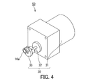
- FIGS. 1 and 2 show an example of the heat transfer device of the present disclosure.
- the heat transfer device includes, for example, a main body 10a.
- the main body 10a includes a first member 11, a first heat transfer body 21, and a second heat transfer body 22.
- the first member 11 contains a first solid material that exhibits a thermoelastic effect.
- the first contact area which is the contact area between the first heat transfer body 21 and the first member 11, varies.
- the second contact area which is the contact area between the second heat transfer body 22 and the first member 11, varies.
- the first contact area when the magnitude of the first external force applied to the first member 11 is smaller than the first threshold value is larger than the first contact area when the magnitude of the first external force is equal to or greater than the first threshold value. Is also big. Therefore, when the magnitude of the first external force is smaller than the first threshold value, heat is easily transferred between the first heat transfer body 21 and the first member 11 by heat conduction.
- the second contact area when the magnitude of the first external force is smaller than the first threshold value is smaller than the second contact area when the magnitude of the first external force is equal to or larger than the first threshold value.
- the first threshold is the threshold of the endothermic reaction and the exothermic reaction in the thermoelastic effect of the first solid material.
- the first contact area and the second contact area can be changed by adjusting the first external force, and the first member 11 is the first heat transfer. It can mediate heat transport between the body 21 and the second heat transfer body 22.
- the thermoelastic effect can be exerted in the first solid material, and the transition heat accompanying the thermoelastic effect can be utilized in the heat transfer device.
- the first contact area is larger than the second contact area.
- heat transfer due to heat conduction tends to be active between the first heat transfer body 21 and the first member 11.
- the first contact area is equal to or less than the second contact area.
- the first contact area may be zero and the second contact area may be zero due to the fluctuation of the magnitude of the first external force.
- the first member 11 and the first heat transfer body 21 may not be in complete contact with each other, and the first member 11 and the second heat transfer body 22 may be in a state where they are not completely in contact with each other. May not be in complete contact with.
- the first solid material when the magnitude of the first external force is smaller than the first threshold value, the first solid material has the first phase, and when the magnitude of the first external force is equal to or larger than the first threshold value, The first solid material has a second phase that is different from the first phase.
- the second phase is, for example, a phase having a standard enthalpy of formation different from the standard enthalpy of formation of the first phase.
- the first solid material is not limited to a specific material as long as it exhibits a thermoelastic effect.
- the first solid material may be, for example, a shape memory alloy, a thermoelastic polymer, or a plastic crystal.
- the shape memory alloy is, for example, a nickel-titanium alloy, a copper-aluminum-nickel alloy, or a copper-zinc-aluminum alloy.
- the thermoelastic polymer may be, for example, a block copolymer of polyethylene terephthalate (PET) and polyethylene oxide (PEO).
- PET polyethylene terephthalate
- PEO polyethylene oxide
- the thermoelastic polymer may be, for example, a block copolymer containing polystyrene and poly (1,4-butadiene).
- the thermoelastic polymer may be, for example, an ABA triblock copolymer composed of poly (2-methyl-2-oxazoline) and polytetrahydrofuran.
- the thermoelastic polymer may be, for example, nylon or natural rubber.
- Plastic crystals include, for example, neopentyl glycol (NPG), pentaglycerin (PG), pentaerythritol (PE), 2-amino-2-methyl-1,3-propanediol (AMP), tris (hydroxymethyl) aminomethane (TRIS), 2-methyl-2-nitro-1-propanol (MNP) and 2-nitro-2-methyl-1,3-propanediol (NMP).
- the first threshold is, for example, about 140 MPa.
- the first threshold value may be defined as a specific value, or may be defined as a set of values between a lower limit value and an upper limit value larger than the lower limit value.
- FIG. 3 is a perspective view showing the first member 11.
- the first member 11 has, for example, a first inner circumference 11u and a first outer circumference 11s.
- the second heat transfer body 22 is arranged to face the first inner circumference 11u
- the first heat transfer body 21 is arranged to face the first outer circumference 11s. ..
- the first heat transfer body 21 may be arranged so as to face the first inner circumference 11u
- the second heat transfer body 22 may be arranged to face the first outer peripheral 11s.
- the first contact area is adjusted by adjusting the first external force so that the first inner circumference 11u or the first outer circumference 11s is brought closer to the first heat transfer body 21 or the second heat transfer body 22.
- the second contact area can be adjusted.
- the first heat transfer body 21 is, for example, an annular component arranged around the first member 11.
- the first heat transfer body 21 is formed of, for example, a metal material such as a metal or an alloy.
- the first heat transfer body 21 may be a hollow part or a solid part. When the first heat transfer body 21 is a hollow component, the inside of the first heat transfer body 21 may be filled with a liquid or powdery substance, or a fluid may flow.
- the second heat transfer body 22 is, for example, a columnar or tubular part, and the first member 11 is arranged around the second heat transfer body 22.
- the second heat transfer body 22 is formed of, for example, a metal material such as a metal or an alloy.
- the second heat transfer body 22 may be a hollow part or a solid part. When the second heat transfer body 22 is a hollow component, the inside of the second heat transfer body 22 may be filled with a liquid or powdery substance, or a fluid may flow.
- the temperature of the first heat transfer body 21 is kept higher than the temperature of the second heat transfer body 22.
- the first member 11 is, for example, a first coil spring.
- the first contact area and the second contact area are adjusted by adjusting the first external force so as to twist the first coil spring 11 or to eliminate the twist of the first coil spring 11. Can be adjusted.
- the first contact area and the second contact area can be adjusted by adjusting the first external force around the axis of the first coil spring.
- the first member 11 may be a tubular component having a slit extending in the axial direction.
- the cross section perpendicular to the axis of the wire rod forming the first coil spring 11 includes, for example, a pair of parallel line segments forming the first inner circumference 11u and the first outer circumference 11s. .. According to such a configuration, it is easy to increase the first contact area and the second contact area.
- the cross section of the wire rod forming the first coil spring 11 perpendicular to the axis may be rectangular. For example, a gap is formed between the surface of the second heat transfer body 22 facing the first inner circumference 11u and the surface of the first heat transfer body 21 facing the first outer circumference 11s.
- the dimension of this gap in the direction perpendicular to the axis of the first coil spring 11 is larger than the distance between the pair of parallel line segments forming the first inner circumference 11u and the first outer circumference 11s.
- the first coil spring 11 is arranged in this gap.
- the main body 10a further includes, for example, a pin 35a, a rotating member 36, and a holding member 40a.
- the rotating member 36 is, for example, an annular member.
- the rotating member 36 is rotatably arranged around the axis of the first member 11 in contact with the first heat transfer body 21 in the axial direction of the first member 11.
- the pin 35a is attached to the rotating member 36, and a part of the pin 35a projects outward in the axial direction of the first member 11.
- One end of the first member 11 is fixed to the rotating member 36.
- the holding member 40a is, for example, an annular member.
- the holding member 40a is arranged in contact with the first heat transfer body 21 in the axial direction of the first member 11, for example.
- the first heat transfer body 21 is arranged between the rotating member 36 and the holding member 40a in the axial direction of the first member 11.
- the end portion of the first coil spring 11 is housed inside the holding member 40a, and the end portion thereof is fixed to the holding member 40a.
- the rotating member 36 is rotated toward the initial position of the pin 35a in the direction indicated by the arrow B. With this rotation, the first external force becomes smaller than the first threshold value, and the second phase shifts to the first phase in the first solid material.
- the temperature of the first member 11 is further lowered by the heat of transition accompanying the phase transition from the second phase to the first phase.
- the pin 35a is returned to the initial position, most of the outer peripheral 11s of the first member 11 comes into contact with the first heat transfer body 21. At this time, the temperature of the first member 11 begins to rise due to the heat conduction between the first member 11 and the first heat transfer body 21.
- the first drive mechanism 30 includes, for example, a motor 31, a rod 32, and a cam 33.
- the rod 32 is connected to the motor 31, and the cam 33 is fixed to the tip of the rod 32.
- the cam 33 is, for example, an elliptical columnar component, and is in contact with, for example, the side surface of the pin 35a.
- the power generated by the motor 31 causes the rod 32 and the cam 33 to rotate around the axis of the rod 32.
- the pin 35a slides on the side surface of the cam 33.
- the motion of rotating the rotating member 36 in the direction indicated by the arrow A and the motion of rotating the rotating member 36 in the direction indicated by the arrow B in FIG. 1 are periodically repeated.
- the heat transfer device 50 can be changed from various viewpoints.
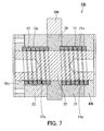
- the heat transfer device 50 may be modified to include the main body 10b shown in FIG. 6 instead of the main body 10a.
- the main body 10b is configured in the same manner as the main body 10a except for a portion to be described in particular.
- the same reference numerals are given to the components of the main body 10b that are the same as or corresponding to the components of the main body 10a, and detailed description thereof will be omitted.
- the description of the body 10a also applies to the body 10b, as long as there is no technical contradiction.
- the main body 10b the first member 11 and the second member 12 and the first heat transfer body 21, the second heat transfer body 22, and the third heat transfer body 23 are connected in series, for example, the first heat transfer body. It is easy to increase the temperature difference between the heat body 21, the second heat transfer body 22, and the third heat transfer body 23.
- the third contact area is equal to or less than the fourth contact area.
- the third contact area is larger than the fourth contact area.
- the third contact area does not have to be less than or equal to the fourth contact area in all periods when the magnitude of the second external force is smaller than the second threshold value.
- the contact area is equal to or less than the fourth contact area.
- the third contact area does not have to be larger than the fourth contact area during all periods when the magnitude of the second external force is equal to or greater than the second threshold value. For example, when the magnitude of the second external force is maximum, the third contact area does not need to be larger. Is larger than the fourth contact area.
- the third contact area may be zero and the fourth contact area may be zero due to the fluctuation of the magnitude of the second external force.
- the second member 12 and the second heat transfer body 22 may not be in complete contact with each other, and the second member 12 and the third heat transfer body 23 may be in a state where they are not completely in contact with each other. May not be in complete contact with.
- the second solid material 12 when the magnitude of the second external force is smaller than the second threshold value, the second solid material 12 has the third phase, and when the magnitude of the second external force is equal to or larger than the second threshold value, the second solid material 12 has a third phase.
- the 2 solid material 12 may have a fourth phase different from the third phase. According to such a configuration, the phase transition of the second solid material can be promoted by changing the magnitude of the second external force according to the second threshold value, and the thermoelastic effect can be exhibited.
- the fourth phase is, for example, a phase having a standard enthalpy of formation different from the standard enthalpy of formation of the third phase.
- the second solid material is not limited to a specific material as long as it exhibits a thermoelastic effect.
- the second solid material can be, for example, the material shown as an example of the first solid material.
- the second solid material may be the same type of material as the first solid material, or may be a different type of material from the first solid material.
- the second threshold is, for example, about 140 MPa.
- the second threshold value may be defined as a specific value, or may be defined as a set of values between a lower limit value and an upper limit value larger than the lower limit value.
- the second member 12 has a second inner circumference 12u and a second outer circumference 12s.
- the second heat transfer body 22 may be arranged so as to face the second inner circumference 12u
- the third heat transfer body 23 may be arranged so as to face the second outer circumference 12s.
- the third heat transfer body 23 may be arranged so as to face the second inner circumference 12u
- the second heat transfer body 22 may be arranged to face the first outer peripheral 11s.
- the third contact area is adjusted by adjusting the second external force so that the second inner circumference 12u or the second outer circumference 12s is brought closer to the second heat transfer body 22 or the third heat transfer body 23.
- the fourth contact area can be adjusted.
- the second member 12 may be a tubular component having a slit extending in the axial direction.
- the second member 12 is a second coil spring.
- the third contact area and the fourth contact area can be adjusted by adjusting the second external force so as to twist the second coil spring 12 or to eliminate the twist of the second coil spring 12. Can be adjusted.
- the third contact area and the fourth contact area can be adjusted by applying a second external force around the axis of the second coil spring.
- the cross section perpendicular to the axis of the wire rod forming the second coil spring 12 includes, for example, a pair of parallel line segments forming the second inner circumference 12u and the second outer circumference 12s. According to such a configuration, it is easy to increase the third contact area and the fourth contact area.
- the cross section of the wire rod forming the second coil spring 12 perpendicular to the axis may be rectangular. For example, a gap is formed between the surface of the second heat transfer body 22 facing the second inner circumference 12u and the surface of the third heat transfer body 23 facing the second outer circumference 12s.
- the dimension of this gap in the direction perpendicular to the axis of the second coil spring 12 is larger than the distance between the pair of parallel line segments forming the second inner circumference 12u and the second outer circumference 12s.
- the second coil spring 12 is arranged in this gap.
- the main body 10b further includes, for example, a pin 35b, a rotating member 36, a first holding member 40b, and a second holding member 40c.
- the pin 35b is attached to the rotating member 36, and a part of the pin 35b projects outward in a direction perpendicular to the axis of the first member 11.
- One ends of the first member 11 and the second member 12 are fixed to the rotating member 36, respectively.
- Each of the first holding member 40b and the second holding member 40c is, for example, an annular member.
- the first holding member 40b is arranged in contact with the first heat transfer body 21 in the axial direction of the first member 11, for example.
- the second holding member 40c is arranged in contact with the third heat transfer body 23 in the axial direction of the second member 12, for example.
- the first heat transfer body 21 is arranged between the rotating member 36 and the first holding member 40b in the axial direction of the first member 11, and the rotating member 36 and the second member 12 are arranged in the axial direction of the second member 12.
- the first heat transfer body 21 is arranged between the two holding members 40c.
- the end of the first coil spring 11 is housed inside the first holding member 40b, and the end thereof is fixed to the holding member 40b.
- the end of the second coil spring 12 is housed inside the second holding member 40c, and the end thereof is fixed to the holding member 40c.
- the second heat transfer body 22 is, for example, a columnar or tubular part, and the first member 11, the second member 12, and the rotation around the second heat transfer body 22.
- the member 36 is arranged.
- the second heat transfer body 22 is formed of, for example, a metal material such as a metal or an alloy.
- the second heat transfer body 22 may be a hollow part or a solid part. When the second heat transfer body 22 is a hollow component, the inside of the second heat transfer body 22 may be filled with a liquid or powdery substance, or a fluid may flow.
- the second member 12 is deformed so as to be pressed against the third heat transfer body 23, and most of the outer circumference 12s of the second member 12 comes into contact with the third heat transfer body 23, and the inside of the second member 12 Most of the circumference 12s is separated from the second heat transfer body 22.
- the temperature of the second member 12 drops due to heat conduction between the second member 12 and the third heat transfer body 23.
- the rotating member 36 is rotated in the opposite direction so as to return the pin 35b to the initial position.
- the second external force becomes smaller than the second threshold value, and the fourth phase shifts to the third phase in the second solid material.
- the temperature of the second member 12 is further lowered by the heat of transition accompanying the phase transition from the fourth phase to the third phase.
- the main body 10b may further include a second drive mechanism in addition to the first drive mechanism 30, for example.
- the second drive mechanism is a mechanism that periodically increases and decreases the second external force.
- the first drive mechanism 30 may also serve as the second drive mechanism.
- the cam 33 of the first drive mechanism 30 is brought into contact with the side surface of the pin 35b.
- the power generated by the motor 31 causes the rod 32 and the cam 33 to rotate around the axis of the rod 32.
- the pin 35b slides on the side surface of the cam 33.
- the second drive mechanism may be configured as a mechanism independent of the first drive mechanism 30.
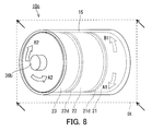
- the main body 10b may be changed as shown in the main body 10c shown in FIGS. 8 to 10.
- the main body 10c is configured in the same manner as the main body 10b except for a portion to be described in particular.
- the same components as or corresponding to the components of the main body 10b are designated by the same reference numerals, and detailed description thereof will be omitted.
- the description of the main bodies 10a and 10b also applies to the main body 10c, unless technically inconsistent.
- the main body 10c has the second member 12 and the third member 12 in addition to the first member 11, the first heat transfer body 21, and the second heat transfer body 22, similarly to the main body 10b. It includes a heat transfer body 23.
- 9 and 10 are cross-sectional views of the main body 10c along the plane IX shown in FIG.
- FIG. 9 shows the state of the main body 10c when the magnitude of the first external force is smaller than the first threshold value and the magnitude of the second external force is smaller than the second threshold value.
- FIG. 10 shows the state of the main body 10c when the magnitude of the first external force is equal to or greater than the first threshold value and the magnitude of the second external force is equal to or greater than the second threshold value.
- the main body 10c is configured so that the third contact area when the magnitude of the second external force is smaller than the second threshold value is larger than the third contact area when the magnitude of the second external force is greater than or equal to the second threshold value. Has been done.
- the main body 10c so that the fourth contact area when the magnitude of the second external force is smaller than the second threshold value is smaller than the fourth contact area when the magnitude of the second external force is greater than or equal to the second threshold value. is configured. According to such a configuration, when the magnitude of the second external force is smaller than the second threshold value, heat is easily transferred between the third heat transfer body 23 and the second member 12 by heat conduction. Further, when the magnitude of the second external force is equal to or larger than the second threshold value, heat is easily transferred between the second heat transfer body 22 and the second member 12 by heat conduction.
- the main body 10c may be further configured as follows. For example, in the main body 10c, when the magnitude of the second external force is smaller than the second threshold value, the third contact area is larger than the fourth contact area. As a result, when the magnitude of the second external force is smaller than the second threshold value, heat transfer due to heat conduction tends to be active between the third heat transfer body 23 and the second member 12. In addition, when the magnitude of the second external force is equal to or greater than the second threshold value, the third contact area is equal to or less than the fourth contact area. When the magnitude of the second external force is equal to or greater than the second threshold value, heat transfer due to heat conduction tends to be active between the second heat transfer body 22 and the second member 12.
- the main body 10c includes a first rotating member 36a and a second rotating member 36b.
- the first rotating member 36a is fixed to the first heat transfer body 21, and the second rotating member 36b is fixed to the third heat transfer body 23.
- the first heat transfer body 21 is formed in a rotating body shape including, for example, a base portion and a protruding portion protruding from the base portion.
- the second heat transfer body 22 is formed in a rotating body shape including, for example, a tubular portion having a bottom portion and a protruding portion protruding from the bottom portion of the tubular portion.
- the third heat transfer body 23 is formed in a rotating body shape including a tubular portion having a bottom portion.
- the axis of the first heat transfer body 21, the axis of the second heat transfer body 22, and the axis of the third heat transfer body 23 extend on the same straight line, for example.
- One end of the first member 11 is fixed to the base of the first heat transfer body 21.
- the other end of the first member 11 is fixed to the inner surface of the bottom portion of the tubular portion of the second heat transfer body 22.
- One end of the second member 12 is fixed to the inner surface of the bottom of the third heat transfer body 23.
- the other end of the second member 12 is fixed to the outer surface of the bottom portion of the tubular portion of the second heat transfer body 22.
- the first member 11 is arranged around the protruding portion of the first heat transfer body 21, and is housed inside the tubular portion of the first heat transfer body 21.
- the second member 12 is arranged around the protruding portion of the second heat transfer body 21, and is housed inside the tubular portion of the third heat transfer body 23.
- the main body 10c further includes a heat insulating material 21d, a heat insulating material 22d, a heat insulating material 22k, and a heat insulating material 23k.
- the thermal conductivity of these heat insulating materials is lower than, for example, the thermal conductivity of the first member 11 and the second member 12.
- the heat insulating material 21d is annular and covers the base portion at the boundary between the base portion and the protruding portion in the first heat transfer body 21.
- the heat insulating material 22d is annular and covers the outer surface of the bottom portion of the second heat transfer body 22 at the boundary between the bottom portion and the protruding portion of the tubular portion.
- the heat insulating material 22k covers the inner surface of the bottom portion of the tubular portion in the second heat transfer body 22.
- the heat insulating material 23k covers the inner surface of the bottom portion of the tubular portion in the third heat transfer body 23.
- the main body 10c further includes, for example, a cylinder 15.
- the first member 11, the second member 12, the first heat transfer body 21, the second heat transfer body 22, and the third heat transfer body 23 are housed inside the cylinder 15.
- the inner surface of the cylinder 15 is made of a heat insulating material.
- the thermal conductivity of this heat insulating material is, for example, lower than the thermal conductivity of the first member 11 and the second member 12.
- the axis of the cylinder 15 extends on the same straight line as, for example, the axis of the first heat transfer body 21, the axis of the second heat transfer body 22, and the axis of the third heat transfer body 23.
- the first rotating member 36a when the first rotating member 36a is rotated in the direction of the arrow A1 in FIG. 8 by a predetermined drive mechanism (not shown), the first external force becomes large and the first external force becomes equal to or higher than the first threshold value. After that, the first rotating member 36a is rotated in the direction of the arrow B1 in FIG. 8 by the driving mechanism, so that the first external force becomes small and the first external force becomes smaller than the first threshold value.
- the second external force is increased by rotating the second rotating member 36b in the direction of the arrow A2 in FIG. 8 by a predetermined drive mechanism (not shown). After that, the second rotating member 36b is rotated in the direction of the arrow B2 in FIG. 8 by the driving mechanism, so that the second external force is reduced.
Abstract
A heat transfer device 50 comprises a first member 11, a first heat transfer element 21, and a second heat transfer element 22. The first member 11 contains a first solid material that exhibits a thermoelastic effect. In the first heat transfer element 21, a first contact area, which is the contact area between the first heat transfer element 21 and the first member 11, varies. In the second heat transfer element 22, a second contact area, which is the contact area between the second heat transfer element 22 and the first member 11, varies. The first contact area when the magnitude of the first external force applied to the first member 11 is smaller than a first threshold is larger than the first contact area when the magnitude of the first external force is equal to or greater than the first threshold. The second contact area when the magnitude of the first external force is smaller than the first threshold is smaller than the second contact area when the magnitude of the first external force is equal to or greater than the first threshold.
Description
本開示は、伝熱装置に関する。
This disclosure relates to a heat transfer device.
従来、熱弾性効果を示す固体材料を伝熱のために用いる技術が知られている。
Conventionally, a technique of using a solid material exhibiting a thermoelastic effect for heat transfer is known.
例えば、特許文献1には、熱弾性効果を示すことが可能な複数の固体冷却材料によって冷却システムの再生器を構成することが記載されている。この冷却システムは、ヒートシンクと、冷凍空間と、再生器とを備えている。固体冷却材料は、例えば、形状記憶合金であり、ワイヤー等の形状に成形されている。
For example, Patent Document 1 describes that a regenerator of a cooling system is composed of a plurality of solid cooling materials capable of exhibiting a thermoelastic effect. The cooling system includes a heat sink, a freezing space, and a regenerator. The solid cooling material is, for example, a shape memory alloy and is molded into a shape such as a wire.
特許文献2には、空気の冷却と加熱を行う冷却加熱モジュールの冷却加熱部のそれぞれにおいて多数の熱歪材料を用いることが記載されている。熱歪材料は、例えば、形状記憶合金によって構成されている。熱歪材料は、上下に延びるワイヤー状に形成されている。
Patent Document 2 describes that a large number of heat strain materials are used in each of the cooling and heating parts of the cooling and heating module that cools and heats air. The thermal strain material is composed of, for example, a shape memory alloy. The heat strain material is formed in the form of wires extending vertically.
特許文献3には、形状記憶合金を活用したヒートポンプが記載されている。形状記憶合金によってベルトが形成されている。
Patent Document 3 describes a heat pump that utilizes a shape memory alloy. The belt is formed of shape memory alloy.
特許文献1から3に記載の技術において、熱弾性効果を示す固体材料を含む部材と伝熱体との接触面積を変化させて熱伝導による伝熱を行うことは想定されていない。
In the techniques described in Patent Documents 1 to 3, it is not assumed that heat transfer by heat conduction is performed by changing the contact area between a member containing a solid material exhibiting a thermoelastic effect and a heat transfer body.
そこで、本開示は、熱弾性効果を示す固体材料を含む部材と伝熱体との接触面積を変化させて熱伝導による伝熱を行うための新規な伝熱装置を提供する。
Therefore, the present disclosure provides a novel heat transfer device for performing heat transfer by heat conduction by changing the contact area between a member containing a solid material exhibiting a thermoelastic effect and a heat transfer body.
本開示は、
熱弾性効果を示す第1固体材料を含む第1部材と、
前記第1部材との間の接触面積である第1接触面積が変動する第1伝熱体と、
前記第1部材との間の接触面積である第2接触面積が変動する第2伝熱体と、を備え、
前記第1部材に加わる第1外力の大きさが前記第1固体材料の前記熱弾性効果における吸熱反応及び発熱反応の閾値である第1閾値より小さいときの前記第1接触面積は、前記第1外力の大きさが前記第1閾値以上であるときの前記第1接触面積よりも大きく、
前記第1外力の大きさが前記第1閾値より小さいときの前記第2接触面積は、前記第1外力の大きさが前記第1閾値以上であるときの前記第2接触面積よりも小さい、
伝熱装置を提供する。 This disclosure is
A first member containing a first solid material exhibiting a thermoelastic effect,
A first heat transfer body in which the first contact area, which is the contact area between the first member, varies.
A second heat transfer body having a variable second contact area, which is a contact area between the first member, is provided.
The first contact area when the magnitude of the first external force applied to the first member is smaller than the first threshold value which is the threshold value of the endothermic reaction and the exothermic reaction in the thermoelastic effect of the first solid material is the first. The magnitude of the external force is larger than the first contact area when it is equal to or greater than the first threshold value.
The second contact area when the magnitude of the first external force is smaller than the first threshold value is smaller than the second contact area when the magnitude of the first external force is equal to or greater than the first threshold value.
Provide a heat transfer device.
本開示の伝熱装置によれば、熱弾性効果を示す固体材料を含む部材と伝熱体との接触面積を変化させて熱伝導による伝熱を行うことができる。
According to the heat transfer device of the present disclosure, heat transfer by heat conduction can be performed by changing the contact area between a member containing a solid material exhibiting a thermoelastic effect and a heat transfer body.
(本開示の基礎となった知見)
特定の伝熱体から別の伝熱体への熱輸送を媒介するために熱弾性効果を示す固体材料を用いることにより、フルオロカーボン及びハイドロフルオロカーボン等を使用することなく、伝熱装置を構成することが考えられる。このような伝熱装置は、オゾン層破壊の防止及び温暖化の防止の観点から有利である。例えば、熱弾性効果を示す固体材料に外力を加えて相転移を生じさせると転移熱が発生する。このような熱弾性効果に伴う吸熱及び発熱を伝熱装置において有効に利用できれば、伝熱装置の価値を高めることができる。加えて、熱弾性効果を示す固体材料と複数の伝熱体とを接触させて熱伝導による伝熱を生じさせることができれば、伝熱装置の特性を高めやすい。 (Knowledge on which this disclosure was based)
By using a solid material exhibiting a thermoelastic effect to mediate heat transfer from a specific heat transfer body to another heat transfer body, a heat transfer device can be constructed without using fluorocarbon, hydrofluorocarbon, or the like. Can be considered. Such a heat transfer device is advantageous from the viewpoint of preventing ozone layer depletion and preventing global warming. For example, when an external force is applied to a solid material exhibiting a thermoelastic effect to cause a phase transition, heat of transition is generated. If the heat absorption and heat generation associated with such a thermoelastic effect can be effectively used in the heat transfer device, the value of the heat transfer device can be increased. In addition, if a solid material exhibiting a thermoelastic effect and a plurality of heat transfer bodies can be brought into contact with each other to generate heat transfer by heat conduction, the characteristics of the heat transfer device can be easily enhanced.
本発明者らは、このような観点から新規な伝熱装置について鋭意検討を重ねた。その結果、本発明者らは、熱弾性効果を示す固体材料に吸熱及び発熱を生じさせるための外力の調整に伴う固体材料の変形を利用して、固体材料と複数の伝熱体との接触面積を所望の状態に調整できることを新たに見出した。本発明者らは、この新たな知見に基づき本開示の伝熱装置を案出した。
The present inventors have made extensive studies on a new heat transfer device from this point of view. As a result, the present inventors utilize the deformation of the solid material due to the adjustment of the external force for causing heat absorption and heat generation in the solid material exhibiting the thermoelastic effect, and make contact between the solid material and the plurality of heat transfer bodies. We have newly found that the area can be adjusted to the desired state. Based on this new finding, the present inventors have devised the heat transfer device of the present disclosure.
(本開示にかかる一態様の概要)
本開示の第1態様に係る伝熱装置は、
熱弾性効果を示す第1固体材料を含む第1部材と、
前記第1部材との間の接触面積である第1接触面積が変動する第1伝熱体と、
前記第1部材との間の接触面積である第2接触面積が変動する第2伝熱体と、を備え、
前記第1部材に加わる第1外力の大きさが前記第1固体材料の前記熱弾性効果における吸熱反応及び発熱反応の閾値である第1閾値より小さいときの前記第1接触面積は、前記第1外力の大きさが前記第1閾値以上であるときの前記第1接触面積よりも大きく、
前記第1外力の大きさが前記第1閾値より小さいときの前記第2接触面積は、前記第1外力の大きさが前記第1閾値以上であるときの前記第2接触面積よりも小さい。 (Summary of one aspect of the present disclosure)
The heat transfer device according to the first aspect of the present disclosure is
A first member containing a first solid material exhibiting a thermoelastic effect,
A first heat transfer body in which the first contact area, which is the contact area between the first member, varies.
A second heat transfer body having a variable second contact area, which is a contact area between the first member, is provided.
The first contact area when the magnitude of the first external force applied to the first member is smaller than the first threshold value which is the threshold value of the endothermic reaction and the exothermic reaction in the thermoelastic effect of the first solid material is the first. The magnitude of the external force is larger than the first contact area when it is equal to or greater than the first threshold value.
The second contact area when the magnitude of the first external force is smaller than the first threshold value is smaller than the second contact area when the magnitude of the first external force is equal to or greater than the first threshold value.
第1態様によれば、第1伝熱体と第1部材との間の接触面積は、第1外力の大きさが第1閾値以上であるときに比べて、第1外力の大きさが第1閾値より小さいときにより大きい。このため、第1外力の大きさが第1閾値より小さいときに、第1伝熱体と第1部材との間で熱伝導により熱が伝わりやすい。一方、第2伝熱体と第1部材との間の接触面積は、第1外力の大きさが第1閾値より小さいときに比べて、第1外力の大きさが第1閾値以上であるときにより大きい。このため、第1外力の大きさが第1閾値以上であるときに、第2伝熱体と第1部材との間で熱伝導により熱が伝わりやすい。このように、第1態様によれば、熱弾性効果を示す固体材料と複数の伝熱体との接触面積を変化させて熱伝導による伝熱を行うことができ、熱弾性効果を示す固体材料は、第1伝熱体と第2伝熱体との間の熱輸送を媒介できる。加えて、第1外力によって第1固体材料において熱弾性効果を発揮させることができ、伝熱装置において第1固体材料の熱弾性効果に伴う吸熱及び発熱を利用できる。
According to the first aspect, the contact area between the first heat transfer body and the first member has a first external force larger than that when the first external force is equal to or larger than the first threshold value. Greater when less than one threshold. Therefore, when the magnitude of the first external force is smaller than the first threshold value, heat is easily transferred between the first heat transfer body and the first member by heat conduction. On the other hand, the contact area between the second heat transfer body and the first member is when the magnitude of the first external force is equal to or greater than the first threshold value as compared with the case where the magnitude of the first external force is smaller than the first threshold value. Greater than. Therefore, when the magnitude of the first external force is equal to or greater than the first threshold value, heat is likely to be transferred between the second heat transfer body and the first member by heat conduction. As described above, according to the first aspect, it is possible to transfer heat by heat transfer by changing the contact area between the solid material exhibiting the thermoelastic effect and the plurality of heat transfer bodies, and the solid material exhibiting the thermoelastic effect. Can mediate heat transport between the first and second heat transfer bodies. In addition, the thermoelastic effect can be exerted on the first solid material by the first external force, and the heat absorption and heat generation associated with the thermoelastic effect of the first solid material can be utilized in the heat transfer device.
本開示の第2態様において、例えば、第1態様に係る伝熱装置では、前記第1外力の大きさが前記第1閾値より小さいときに、前記第1接触面積は、前記第2接触面積より大きく、前記第1外力の大きさが前記第1閾値以上であるときに、前記第1接触面積は、前記第2接触面積以下であってもよい。第2態様によれば、第1外力の大きさが第1閾値より小さいときに第1伝熱体と第1部材との間で熱伝導による伝熱が盛んになりやすい。加えて、第1外力の大きさが第1閾値以上であるときに第2伝熱体と第1部材との間で熱伝導による伝熱が盛んになりやすい。
In the second aspect of the present disclosure, for example, in the heat transfer device according to the first aspect, when the magnitude of the first external force is smaller than the first threshold value, the first contact area is larger than the second contact area. When the magnitude of the first external force is large and is equal to or greater than the first threshold value, the first contact area may be equal to or smaller than the second contact area. According to the second aspect, when the magnitude of the first external force is smaller than the first threshold value, heat transfer by heat conduction tends to be active between the first heat transfer body and the first member. In addition, when the magnitude of the first external force is equal to or greater than the first threshold value, heat transfer due to heat conduction tends to be active between the second heat transfer body and the first member.
本開示の第3態様において、例えば、第1態様又は第2態様に係る伝熱装置では、前記第1外力の大きさが前記第1閾値より小さいときに、前記第1固体材料は、第1相を有し、前記第1外力の大きさが前記第1閾値以上であるときに、前記第1固体材料は、前記第1相と異なる第2相を有してもよい。第3態様によれば、第1外力の大きさを第1閾値に応じて変化させることにより第1固体材料の相転移を促し、熱弾性効果を発揮させることができる。
In the third aspect of the present disclosure, for example, in the heat transfer device according to the first aspect or the second aspect, when the magnitude of the first external force is smaller than the first threshold value, the first solid material is the first. The first solid material may have a second phase different from the first phase when it has a phase and the magnitude of the first external force is equal to or greater than the first threshold value. According to the third aspect, the phase transition of the first solid material can be promoted by changing the magnitude of the first external force according to the first threshold value, and the thermoelastic effect can be exhibited.
本開示の第4態様において、例えば、第1態様から第3態様のいずれか1つの態様に係る伝熱装置では、前記第1部材は、第1内周と第1外周とを有し、前記第1伝熱体及び前記第2伝熱体の一方は、前記第1内周に向かい合って配置され、前記第1伝熱体及び前記第2伝熱体の他方は、前記第1外周に向かい合って配置されていてもよい。第4態様によれば、第1伝熱体又は第2伝熱体に第1部材の第1内周又は第1外周を近づけるように、第1外力を調整することにより、第1接触面積及び第2接触面積を調整できる。
In the fourth aspect of the present disclosure, for example, in the heat transfer device according to any one of the first to third aspects, the first member has a first inner circumference and a first outer circumference. One of the first heat transfer body and the second heat transfer body is arranged so as to face the first inner circumference, and the other of the first heat transfer body and the second heat transfer body faces the first outer circumference. May be arranged. According to the fourth aspect, the first contact area and the first contact area are adjusted by adjusting the first external force so that the first inner circumference or the first outer circumference of the first member is brought closer to the first heat transfer body or the second heat transfer body. The second contact area can be adjusted.
本開示の第5態様において、例えば、第4態様に係る伝熱装置では、前記第1部材は、第1コイルばねであってもよい。第5態様によれば、第1コイルばねの軸線周りに第1外力を調整することにより、第1接触面積及び第2接触面積を調整できる。
In the fifth aspect of the present disclosure, for example, in the heat transfer device according to the fourth aspect, the first member may be a first coil spring. According to the fifth aspect, the first contact area and the second contact area can be adjusted by adjusting the first external force around the axis of the first coil spring.
本開示の第6態様において、例えば、第5態様に係る伝熱装置では、前記第1コイルばねをなす線材の軸線に垂直な断面は、前記第1内周及び前記第1外周をなす一対の平行な線分を含んでいてもよい。第6態様によれば、第1接触面積及び第2接触面積を大きくしやすい。
In the sixth aspect of the present disclosure, for example, in the heat transfer device according to the fifth aspect, a pair of cross sections perpendicular to the axis of the wire rod forming the first coil spring form the first inner circumference and the first outer circumference. It may contain parallel line segments. According to the sixth aspect, it is easy to increase the first contact area and the second contact area.
本開示の第7態様において、例えば、第1態様から第6態様のいずれか1つの態様に係る伝熱装置では、前記第1外力を周期的に増加及び減少させる第1駆動機構をさらに備えていてもよい。第7態様によれば、第1駆動機構によって第1外力を周期的に増加及び減少させることができる。
In the seventh aspect of the present disclosure, for example, the heat transfer device according to any one of the first to sixth aspects further includes a first drive mechanism for periodically increasing and decreasing the first external force. You may. According to the seventh aspect, the first external force can be periodically increased and decreased by the first driving mechanism.
本開示の第8態様において、例えば、第1態様から第7態様のいずれか1つの態様に係る伝熱装置は、
熱弾性効果を示す第2固体材料を含む第2部材と、
前記第2部材との間の接触面積である第3接触面積が変動する第3伝熱体と、をさらに備え、
前記第2部材に加わる第2外力の大きさの変動により前記第2部材と前記第2伝熱体との接触面積である第4接触面積が変動し、
前記第2外力の大きさが前記第2固体材料の前記熱弾性効果における吸熱反応及び発熱反応の閾値である第2閾値より小さいときの前記第3接触面積は、前記第2外力の大きさが前記第2閾値以上であるときの前記第3接触面積よりも小さく、前記第2外力の大きさが前記第2閾値より小さいときの前記第4接触面積は、前記第2外力の大きさが前記第2閾値以上であるときの前記第4接触面積よりも大きくてもよい。 In the eighth aspect of the present disclosure, for example, the heat transfer device according to any one of the first to seventh aspects is
A second member containing a second solid material exhibiting a thermoelastic effect,
A third heat transfer body in which the third contact area, which is the contact area between the second member, varies, is further provided.
The fourth contact area, which is the contact area between the second member and the second heat transfer body, fluctuates due to the fluctuation of the magnitude of the second external force applied to the second member.
When the magnitude of the second external force is smaller than the second threshold value which is the threshold value of the heat absorption reaction and the exothermic reaction in the thermoelastic effect of the second solid material, the magnitude of the second external force is the magnitude of the second external force. The fourth contact area, which is smaller than the third contact area when it is equal to or more than the second threshold value and the magnitude of the second external force is smaller than the second threshold value, has the magnitude of the second external force. It may be larger than the fourth contact area when it is equal to or more than the second threshold value.
第8態様によれば、第3伝熱体と第2部材との間の接触面積は、第2外力の大きさが第2閾値より小さいときに比べて、第2外力の大きさが第2閾値以上であるときにより大きい。このため、第2外力の大きさが第2閾値以上であるときに、第3伝熱体と第2部材との間で熱伝導により熱が伝わりやすい。一方、第2伝熱体と第2部材との間の接触面積は、第2外力の大きさが第2閾値以上であるときに比べて、第2外力の大きさが第2閾値より小さいときにより大きい。このため、第2外力の大きさが第2閾値より小さいときに、第2伝熱体と第2部材との間で熱伝導により熱が伝わりやすい。このように、第8態様によれば、熱弾性効果を示す固体材料を含む複数の部材と、3つ以上の伝熱体とが直列に接続され、複数の伝熱体における温度差を大きくしやすい。
According to the eighth aspect, the contact area between the third heat transfer body and the second member has a second external force larger than that when the second external force is smaller than the second threshold value. Greater when above the threshold. Therefore, when the magnitude of the second external force is equal to or greater than the second threshold value, heat is likely to be transferred between the third heat transfer body and the second member by heat conduction. On the other hand, the contact area between the second heat transfer body and the second member is when the magnitude of the second external force is smaller than the second threshold value as compared with the case where the magnitude of the second external force is equal to or larger than the second threshold value. Greater than. Therefore, when the magnitude of the second external force is smaller than the second threshold value, heat is easily transferred between the second heat transfer body and the second member by heat conduction. As described above, according to the eighth aspect, a plurality of members including a solid material exhibiting a thermoelastic effect and three or more heat transfer bodies are connected in series to increase the temperature difference between the plurality of heat transfer bodies. Cheap.
本開示の第9態様において、例えば、第8態様に係る伝熱装置では、前記第2外力の大きさが前記第2閾値より小さいときに、前記第3接触面積は前記第4接触面積以下であり、前記第2外力の大きさが前記第2閾値以上であるときに、前記第3接触面積は前記第4接触面積より大きくてもよい。第9態様によれば、第2外力の大きさが第2閾値より小さいときに第2伝熱体と第2部材との間で熱伝導による伝熱が盛んになりやすい。加えて、第2外力の大きさが第2閾値以上であるときに第3伝熱体と第2部材との間で熱伝導による伝熱が盛んになりやすい。
In the ninth aspect of the present disclosure, for example, in the heat transfer device according to the eighth aspect, when the magnitude of the second external force is smaller than the second threshold value, the third contact area is equal to or less than the fourth contact area. When the magnitude of the second external force is equal to or greater than the second threshold value, the third contact area may be larger than the fourth contact area. According to the ninth aspect, when the magnitude of the second external force is smaller than the second threshold value, heat transfer by heat conduction tends to be active between the second heat transfer body and the second member. In addition, when the magnitude of the second external force is equal to or greater than the second threshold value, heat transfer due to heat conduction tends to be active between the third heat transfer body and the second member.
本開示の第10態様において、例えば、第1態様から第7態様のいずれか1つの態様に係る伝熱装置は、
熱弾性効果を示す第2固体材料を含む第2部材と、
前記第2部材との間の接触面積である第3接触面積が変動する第3伝熱体と、をさらに備え、
前記第2部材に加わる第2外力の大きさの変動により前記第2部材と前記第2伝熱体との接触面積である第4接触面積が変動し、
前記第2外力の大きさが前記第2固体材料の前記熱弾性効果における吸熱反応及び発熱反応の閾値である第2閾値より小さいときの前記第3接触面積は、前記第2外力の大きさが前記第2閾値以上であるときの前記第3接触面積よりも大きく、前記第2外力の大きさが前記第2閾値より小さいときの前記第4接触面積は、前記第2外力の大きさが前記第2閾値以上であるときの前記第4接触面積よりも小さくてもよい。 In the tenth aspect of the present disclosure, for example, the heat transfer device according to any one of the first to seventh aspects is
A second member containing a second solid material exhibiting a thermoelastic effect,
A third heat transfer body in which the third contact area, which is the contact area between the second member, varies, is further provided.
The fourth contact area, which is the contact area between the second member and the second heat transfer body, fluctuates due to the fluctuation of the magnitude of the second external force applied to the second member.
When the magnitude of the second external force is smaller than the second threshold value which is the threshold value of the heat absorption reaction and the exothermic reaction in the thermoelastic effect of the second solid material, the magnitude of the second external force is the magnitude of the second external force. The fourth contact area, which is larger than the third contact area when the second threshold value or more and the magnitude of the second external force is smaller than the second threshold value, has the magnitude of the second external force. It may be smaller than the fourth contact area when it is equal to or more than the second threshold value.
第10態様によれば、第3伝熱体と第2部材との間の接触面積は、第2外力の大きさが第2閾値以上であるときに比べて、第2外力の大きさが第2閾値より小さいときにより大きい。このため、第2外力の大きさが第2閾値より小さいときに、第3伝熱体と第2部材との間で熱伝導により熱が伝わりやすい。一方、第2伝熱体と第2部材との間の接触面積は、第2外力の大きさが第2閾値より小さいときに比べて、第2外力の大きさが第2閾値以上であるときにより大きい。このため、第2外力の大きさが第2閾値以上であるときに、第2伝熱体と第2部材との間で熱伝導により熱が伝わりやすい。このように、第10態様によれば、熱弾性効果を示す固体材料を含む複数の部材と、3つ以上の伝熱体とを直列に接続でき、複数の伝熱体における温度差を大きくしやすい。
According to the tenth aspect, the contact area between the third heat transfer body and the second member has a second external force larger than that when the second external force is equal to or larger than the second threshold value. Greater when less than 2 thresholds. Therefore, when the magnitude of the second external force is smaller than the second threshold value, heat is easily transferred between the third heat transfer body and the second member by heat conduction. On the other hand, the contact area between the second heat transfer body and the second member is when the magnitude of the second external force is equal to or greater than the second threshold value as compared with the case where the magnitude of the second external force is smaller than the second threshold value. Greater than. Therefore, when the magnitude of the second external force is equal to or greater than the second threshold value, heat is likely to be transferred between the second heat transfer body and the second member by heat conduction. As described above, according to the tenth aspect, a plurality of members including a solid material exhibiting a thermoelastic effect and three or more heat transfer bodies can be connected in series, and the temperature difference between the plurality of heat transfer bodies is increased. Cheap.
本開示の第11態様において、例えば、第10態様に係る伝熱装置では、前記第2外力の大きさが前記第2閾値より小さいときに、前記第3接触面積は前記第4接触面積より大きく、前記第2外力の大きさが前記第2閾値以上であるときに、前記第3接触面積は前記第4接触面積以下であってもよい。第11態様によれば、第2外力の大きさが第2閾値より小さいときに第3伝熱体と第2部材との間で熱伝導による伝熱が盛んになりやすい。加えて、第2外力の大きさが第2閾値以上であるときに第2伝熱体と第2部材との間で熱伝導による伝熱が盛んになりやすい。
In the eleventh aspect of the present disclosure, for example, in the heat transfer device according to the tenth aspect, when the magnitude of the second external force is smaller than the second threshold value, the third contact area is larger than the fourth contact area. When the magnitude of the second external force is equal to or greater than the second threshold value, the third contact area may be equal to or smaller than the fourth contact area. According to the eleventh aspect, when the magnitude of the second external force is smaller than the second threshold value, heat transfer by heat conduction tends to be active between the third heat transfer body and the second member. In addition, when the magnitude of the second external force is equal to or greater than the second threshold value, heat transfer due to heat conduction tends to be active between the second heat transfer body and the second member.
本開示の第12態様において、例えば、第8態様から第11態様のいずれか1つの態様に係る伝熱装置では、前記第2外力の大きさが前記第2閾値より小さいときに、前記第2固体材料は、第3相を有し、前記第2外力の大きさが前記第2閾値以上であるときに、前記第2固体材料は、前記第3相と異なる第4相を有してもよい。第12態様によれば、第2外力の大きさを第2閾値に応じて変化させることにより第2固体材料の相転移を促し、熱弾性効果を発揮させることができる。
In the twelfth aspect of the present disclosure, for example, in the heat transfer device according to any one of the eighth to eleventh aspects, when the magnitude of the second external force is smaller than the second threshold value, the second aspect is described. The solid material has a third phase, and when the magnitude of the second external force is equal to or greater than the second threshold value, the second solid material may have a fourth phase different from the third phase. Good. According to the twelfth aspect, the phase transition of the second solid material can be promoted by changing the magnitude of the second external force according to the second threshold value, and the thermoelastic effect can be exhibited.
本開示の第13態様において、例えば、第8態様から第12態様のいずれか1つの態様に係る伝熱装置では、前記第2部材は、第2内周と第2外周とを有し、前記第2伝熱体及び前記第3伝熱体の一方は、前記第2内周に向かい合って配置され、前記第2伝熱体及び前記第3伝熱体の他方は、前記第2外周に向かい合って配置されていてもよい。第13態様によれば、第2伝熱体又は第3伝熱体に第2部材の第2内周又は第2外周を近づけるように、第2外力を調整することにより、第3接触面積及び第4接触面積を調整できる。
In the thirteenth aspect of the present disclosure, for example, in the heat transfer device according to any one of the eighth to twelfth aspects, the second member has a second inner circumference and a second outer circumference, and the said One of the second heat transfer body and the third heat transfer body is arranged so as to face the second inner circumference, and the other of the second heat transfer body and the third heat transfer body faces the second outer circumference. May be arranged. According to the thirteenth aspect, the third contact area and the third contact area are adjusted by adjusting the second external force so that the second inner circumference or the second outer circumference of the second member is brought closer to the second heat transfer body or the third heat transfer body. The fourth contact area can be adjusted.
本開示の第14態様において、第8態様から第13態様のいずれか1つの態様に係る伝熱装置では、前記第2部材は、第2コイルばねであってもよい。第14態様によれば、第2コイルばねの軸線周りに第2外力を調整することにより、第3接触面積及び第4接触面積を調整できる。
In the 14th aspect of the present disclosure, in the heat transfer device according to any one of the 8th to 13th aspects, the second member may be a second coil spring. According to the fourteenth aspect, the third contact area and the fourth contact area can be adjusted by adjusting the second external force around the axis of the second coil spring.
本開示の第15態様において、例えば、第8態様から第14態様のいずれか1つの態様に係る伝熱装置では、前記第2コイルばねをなす線材の軸線に垂直な断面は、前記第2内周及び前記第2外周をなす一対の平行な線分を含んでいてもよい。第15態様によれば、第3接触面積及び第4接触面積を大きくしやすい。
In the fifteenth aspect of the present disclosure, for example, in the heat transfer device according to any one of the eighth to the fourteenth aspects, the cross section of the wire rod forming the second coil spring is formed in the second aspect. It may include a pair of parallel line segments forming the circumference and the second outer circumference. According to the fifteenth aspect, it is easy to increase the third contact area and the fourth contact area.
本開示の第16態様において、例えば、第8態様から第15態様のいずれか1つの態様に係る伝熱装置では、前記第2外力を周期的に増加及び減少させる第2駆動機構をさらに備えていてもよい。第16態様によれば、第2駆動機構によって第2外力を周期的に増加及び減少させることができる。
In the 16th aspect of the present disclosure, for example, the heat transfer device according to any one of the 8th to 15th aspects further includes a second drive mechanism for periodically increasing and decreasing the second external force. You may. According to the 16th aspect, the second external force can be periodically increased and decreased by the second driving mechanism.
以下、本開示の実施形態について、図面を参照しながら説明する。以下の実施形態は例示に過ぎず、本開示は、以下の実施形態に限定されない。
Hereinafter, embodiments of the present disclosure will be described with reference to the drawings. The following embodiments are merely examples, and the present disclosure is not limited to the following embodiments.
図1及び2は、本開示の伝熱装置の一例を示す。伝熱装置は、例えば、本体10aを備えている。本体10aは、第1部材11と、第1伝熱体21と、第2伝熱体22とを備えている。第1部材11は、熱弾性効果を示す第1固体材料を含んでいる。第1伝熱体21において、第1伝熱体21と第1部材11との間の接触面積である第1接触面積が変動する。第2伝熱体22において、第2伝熱体22と第1部材11との間の接触面積である第2接触面積が変動する。本体10aにおいて、第1部材11に加わる第1外力の大きさが第1閾値より小さいときの第1接触面積は、第1外力の大きさが第1閾値以上であるときの第1接触面積よりも大きい。このため、第1外力の大きさが第1閾値より小さいときに、第1伝熱体21と第1部材11との間で熱伝導により熱が伝わりやすい。一方、本体10aにおいて、第1外力の大きさが第1閾値より小さいときの第2接触面積は、第1外力の大きさが第1閾値以上であるときの第2接触面積よりも小さい。第1閾値は、第1固体材料の熱弾性効果における吸熱反応及び発熱反応の閾値である。第1外力の大きさが第1閾値以上であるときに、第2伝熱体22と第1部材11との間で熱伝導により熱が伝わりやすい。このように、本体10aを備えた伝熱装置によれば、第1外力を調整することによって、第1接触面積及び第2接触面積を変動させることができ、第1部材11が第1伝熱体21と第2伝熱体22との間の熱輸送を媒介できる。加えて、第1外力を調整することによって第1固体材料において熱弾性効果を発揮させることができ、伝熱装置において熱弾性効果に伴う転移熱を利用できる。
FIGS. 1 and 2 show an example of the heat transfer device of the present disclosure. The heat transfer device includes, for example, a main body 10a. The main body 10a includes a first member 11, a first heat transfer body 21, and a second heat transfer body 22. The first member 11 contains a first solid material that exhibits a thermoelastic effect. In the first heat transfer body 21, the first contact area, which is the contact area between the first heat transfer body 21 and the first member 11, varies. In the second heat transfer body 22, the second contact area, which is the contact area between the second heat transfer body 22 and the first member 11, varies. In the main body 10a, the first contact area when the magnitude of the first external force applied to the first member 11 is smaller than the first threshold value is larger than the first contact area when the magnitude of the first external force is equal to or greater than the first threshold value. Is also big. Therefore, when the magnitude of the first external force is smaller than the first threshold value, heat is easily transferred between the first heat transfer body 21 and the first member 11 by heat conduction. On the other hand, in the main body 10a, the second contact area when the magnitude of the first external force is smaller than the first threshold value is smaller than the second contact area when the magnitude of the first external force is equal to or larger than the first threshold value. The first threshold is the threshold of the endothermic reaction and the exothermic reaction in the thermoelastic effect of the first solid material. When the magnitude of the first external force is equal to or greater than the first threshold value, heat is easily transferred between the second heat transfer body 22 and the first member 11 by heat conduction. As described above, according to the heat transfer device provided with the main body 10a, the first contact area and the second contact area can be changed by adjusting the first external force, and the first member 11 is the first heat transfer. It can mediate heat transport between the body 21 and the second heat transfer body 22. In addition, by adjusting the first external force, the thermoelastic effect can be exerted in the first solid material, and the transition heat accompanying the thermoelastic effect can be utilized in the heat transfer device.
本体10aにおいて、例えば、第1外力の大きさが第1閾値より小さいときに、第1接触面積は、第2接触面積より大きい。これにより、第1外力の大きさが第1閾値より小さいときに、第1伝熱体21と第1部材11との間で熱伝導による伝熱が盛んになりやすい。加えて、本体10aにおいて、例えば、第1外力の大きさが第1閾値以上であるときに、第1接触面積は、第2接触面積以下である。これにより、第1外力の大きさが第1閾値以上であるときに第2伝熱体22と第1部材11との間で熱伝導による伝熱が盛んになりやすい。なお、第1外力の大きさが第1閾値より小さい全ての期間において第1接触面積が第2接触面積より大きい必要はなく、例えば、第1外力の大きさが最小であるときに第1接触面積が第2接触面積より大きい。第1外力の大きさが第1閾値以上である全ての期間において第1接触面積が第2接触面積以下である必要はなく、例えば、第1外力の大きさが最大であるときに第1接触面積が第2接触面積より大きい。
In the main body 10a, for example, when the magnitude of the first external force is smaller than the first threshold value, the first contact area is larger than the second contact area. As a result, when the magnitude of the first external force is smaller than the first threshold value, heat transfer due to heat conduction tends to be active between the first heat transfer body 21 and the first member 11. In addition, in the main body 10a, for example, when the magnitude of the first external force is equal to or greater than the first threshold value, the first contact area is equal to or less than the second contact area. As a result, when the magnitude of the first external force is equal to or greater than the first threshold value, heat transfer due to heat conduction tends to be active between the second heat transfer body 22 and the first member 11. The first contact area does not have to be larger than the second contact area in all periods when the magnitude of the first external force is smaller than the first threshold value. For example, the first contact is when the magnitude of the first external force is the minimum. The area is larger than the second contact area. The first contact area does not have to be less than or equal to the second contact area during all periods when the magnitude of the first external force is greater than or equal to the first threshold value. The area is larger than the second contact area.
第1外力の大きさの変動により、第1接触面積はゼロになってもよく、第2接触面積はゼロになってもよい。換言すると、第1外力の大きさに応じて、第1部材11と第1伝熱体21とが完全に接触していない状態になってもよく、第1部材11と第2伝熱体22とが完全に接触していない状態になってもよい。
The first contact area may be zero and the second contact area may be zero due to the fluctuation of the magnitude of the first external force. In other words, depending on the magnitude of the first external force, the first member 11 and the first heat transfer body 21 may not be in complete contact with each other, and the first member 11 and the second heat transfer body 22 may be in a state where they are not completely in contact with each other. May not be in complete contact with.
本体10aにおいて、例えば、第1外力の大きさが第1閾値より小さいときに、第1固体材料は、第1相を有し、第1外力の大きさが第1閾値以上であるときに、第1固体材料は、第1相と異なる第2相を有する。第1外力の大きさを第1閾値に応じて変化させることにより第1固体材料の相転移を促し、熱弾性効果を発揮させることができる。第2相は、例えば、第1相の標準生成エンタルピーと異なる標準生成エンタルピーを有する相である。
In the main body 10a, for example, when the magnitude of the first external force is smaller than the first threshold value, the first solid material has the first phase, and when the magnitude of the first external force is equal to or larger than the first threshold value, The first solid material has a second phase that is different from the first phase. By changing the magnitude of the first external force according to the first threshold value, the phase transition of the first solid material can be promoted and the thermoelastic effect can be exhibited. The second phase is, for example, a phase having a standard enthalpy of formation different from the standard enthalpy of formation of the first phase.
第1固体材料は、熱弾性効果を示す限り特定の材料に限定されない。第1固体材料は、例えば、形状記憶合金であってもよく、熱弾性ポリマーであってもよく、柔粘性結晶であってもよい。形状記憶合金は、例えば、ニッケル-チタン合金、銅-アルミニウム-ニッケル合金、銅-亜鉛-アルミニウム合金である。熱弾性ポリマーは、例えば、ポリエチレンテレフタレート(PET)とポリエチレンオキシド(PEO)とのブロック共重合体であってもよい。熱弾性ポリマーは、例えば、ポリスチレンとポリ(1,4-ブタジエン)とを含有するブロック共重合体であってもよい。熱弾性ポリマーは、例えば、ポリ(2-メチル-2-オキサゾリン)とポリテトラヒドロフランとからなるABAトリブロック共重合体であってもよい。熱弾性ポリマーは、例えば、ナイロン又は天然ゴムであってもよい。柔粘性結晶は、例えば、ネオペンチルグリコール(NPG)、pentaglycerin(PG)、pentaerythritol(PE)、2-amino-2-methyl-1,3-propanediol(AMP)、tris(hydroxymethyl)aminomethane(TRIS)、2-methyl-2-nitro-1-propanol(MNP)、及び2-nitro-2-methyl-1,3-propanediol(NMP)である。
The first solid material is not limited to a specific material as long as it exhibits a thermoelastic effect. The first solid material may be, for example, a shape memory alloy, a thermoelastic polymer, or a plastic crystal. The shape memory alloy is, for example, a nickel-titanium alloy, a copper-aluminum-nickel alloy, or a copper-zinc-aluminum alloy. The thermoelastic polymer may be, for example, a block copolymer of polyethylene terephthalate (PET) and polyethylene oxide (PEO). The thermoelastic polymer may be, for example, a block copolymer containing polystyrene and poly (1,4-butadiene). The thermoelastic polymer may be, for example, an ABA triblock copolymer composed of poly (2-methyl-2-oxazoline) and polytetrahydrofuran. The thermoelastic polymer may be, for example, nylon or natural rubber. Plastic crystals include, for example, neopentyl glycol (NPG), pentaglycerin (PG), pentaerythritol (PE), 2-amino-2-methyl-1,3-propanediol (AMP), tris (hydroxymethyl) aminomethane (TRIS), 2-methyl-2-nitro-1-propanol (MNP) and 2-nitro-2-methyl-1,3-propanediol (NMP).
例えば、第1固体材料がニッケル-チタン合金である場合、第1相及び第2相の一方はオーステナイト相であり、第1相及び第2相の他方はマルテンサイト相である。この場合、第1閾値は、例えば約140MPaである。なお、第1閾値は、特定の値として定められていてもよいし、下限値と下限値より大きい上限値との間の値の集合として定められていてもよい。
For example, when the first solid material is a nickel-titanium alloy, one of the first and second phases is an austenite phase, and the other of the first and second phases is a martensite phase. In this case, the first threshold is, for example, about 140 MPa. The first threshold value may be defined as a specific value, or may be defined as a set of values between a lower limit value and an upper limit value larger than the lower limit value.
図3は、第1部材11を示す斜視図である。第1部材11は、例えば、第1内周11uと第1外周11sとを有する。図2に示す通り、本体10aにおいて、例えば、第2伝熱体22は、第1内周11uに向かい合って配置され、第1伝熱体21は、第1外周11sに向かい合って配置されている。なお、第1伝熱体21が第1内周11uに向かい合って配置され、第2伝熱体22が第1外周11sに向かい合って配置されるように変更されてもよい。このような構成によれば、第1伝熱体21又は第2伝熱体22に第1内周11u又は第1外周11sを近づけるように、第1外力を調整することにより、第1接触面積及び第2接触面積を調整できる。
FIG. 3 is a perspective view showing the first member 11. The first member 11 has, for example, a first inner circumference 11u and a first outer circumference 11s. As shown in FIG. 2, in the main body 10a, for example, the second heat transfer body 22 is arranged to face the first inner circumference 11u, and the first heat transfer body 21 is arranged to face the first outer circumference 11s. .. The first heat transfer body 21 may be arranged so as to face the first inner circumference 11u, and the second heat transfer body 22 may be arranged to face the first outer peripheral 11s. According to such a configuration, the first contact area is adjusted by adjusting the first external force so that the first inner circumference 11u or the first outer circumference 11s is brought closer to the first heat transfer body 21 or the second heat transfer body 22. And the second contact area can be adjusted.
本体10aにおいて、第1伝熱体21は、例えば、第1部材11の周りに配置された環状の部品である。第1伝熱体21は、例えば、金属又は合金等の金属材料によって形成されている。第1伝熱体21は、中空の部品であってもよく、中実の部品であってもよい。第1伝熱体21が中空の部品である場合、第1伝熱体21の内部には、液状又は粉状の物質が充填されていてもよく、流体が流れていてもよい。
In the main body 10a, the first heat transfer body 21 is, for example, an annular component arranged around the first member 11. The first heat transfer body 21 is formed of, for example, a metal material such as a metal or an alloy. The first heat transfer body 21 may be a hollow part or a solid part. When the first heat transfer body 21 is a hollow component, the inside of the first heat transfer body 21 may be filled with a liquid or powdery substance, or a fluid may flow.
本体10aにおいて、第2伝熱体22は、例えば、柱状又は筒状の部品であり、第2伝熱体22の周りに第1部材11が配置されている。第2伝熱体22は、例えば、金属又は合金等の金属材料によって形成されている。第2伝熱体22は、中空の部品であってもよく、中実の部品であってもよい。第2伝熱体22が中空の部品である場合、第2伝熱体22の内部には、液状又は粉状の物質が充填されていてもよく、流体が流れていてもよい。
In the main body 10a, the second heat transfer body 22 is, for example, a columnar or tubular part, and the first member 11 is arranged around the second heat transfer body 22. The second heat transfer body 22 is formed of, for example, a metal material such as a metal or an alloy. The second heat transfer body 22 may be a hollow part or a solid part. When the second heat transfer body 22 is a hollow component, the inside of the second heat transfer body 22 may be filled with a liquid or powdery substance, or a fluid may flow.
本体10aにおいて、例えば、第1伝熱体21の温度は、第2伝熱体22の温度より高く保たれている。
In the main body 10a, for example, the temperature of the first heat transfer body 21 is kept higher than the temperature of the second heat transfer body 22.
図3に示す通り、第1部材11は、例えば、第1コイルばねである。このような構成によれば、第1コイルばね11をねじるように又は第1コイルばね11のねじりが解消されるように第1外力を調整することにより、第1接触面積及び第2接触面積を調整できる。換言すると、第1コイルばねの軸線周りに第1外力を調整することにより、第1接触面積及び第2接触面積を調整できる。第1部材11は、軸線方向に延びるスリットを有する筒状の部品であってもよい。
As shown in FIG. 3, the first member 11 is, for example, a first coil spring. According to such a configuration, the first contact area and the second contact area are adjusted by adjusting the first external force so as to twist the first coil spring 11 or to eliminate the twist of the first coil spring 11. Can be adjusted. In other words, the first contact area and the second contact area can be adjusted by adjusting the first external force around the axis of the first coil spring. The first member 11 may be a tubular component having a slit extending in the axial direction.
図2に示す通り、本体10aにおいて、第1コイルばね11をなす線材の軸線に垂直な断面は、例えば、第1内周11u及び第1外周11sをなす一対の平行な線分を含んでいる。このような構成によれば、第1接触面積及び第2接触面積を大きくしやすい。第1コイルばね11をなす線材の軸線に垂直な断面は、矩形であってもよい。例えば、第1内周11uに向かい合っている第2伝熱体22の面と、第1外周11sに向かい合っている第1伝熱体21の面との間には、隙間が形成されている。第1コイルばね11の軸線に垂直な方向におけるこの隙間の寸法は、第1内周11u及び第1外周11sをなす一対の平行な線分同士の距離より大きい。この隙間に、第1コイルばね11が配置されている。
As shown in FIG. 2, in the main body 10a, the cross section perpendicular to the axis of the wire rod forming the first coil spring 11 includes, for example, a pair of parallel line segments forming the first inner circumference 11u and the first outer circumference 11s. .. According to such a configuration, it is easy to increase the first contact area and the second contact area. The cross section of the wire rod forming the first coil spring 11 perpendicular to the axis may be rectangular. For example, a gap is formed between the surface of the second heat transfer body 22 facing the first inner circumference 11u and the surface of the first heat transfer body 21 facing the first outer circumference 11s. The dimension of this gap in the direction perpendicular to the axis of the first coil spring 11 is larger than the distance between the pair of parallel line segments forming the first inner circumference 11u and the first outer circumference 11s. The first coil spring 11 is arranged in this gap.
図2に示す通り、本体10aは、例えば、ピン35a、回転部材36、及び保持部材40aをさらに備えている。回転部材36は、例えば、環状の部材である。回転部材36は、第1部材11の軸線方向において第1伝熱体21に接して、第1部材11の軸線周りに回転可能に配置されている。ピン35aは、回転部材36に取り付けられており、ピン35aの一部は、第1部材11の軸線方向において外側に突出している。第1部材11の一端は、回転部材36に固定されている。保持部材40aは、例えば、環状の部材である。保持部材40aは、例えば、第1部材11の軸線方向において第1伝熱体21に接して配置されている。例えば、第1部材11の軸線方向において、回転部材36と保持部材40aとの間に第1伝熱体21が配置されている。第1コイルばね11の端部は、保持部材40aの内部に収容されており、その端部は保持部材40aに固定されている。
As shown in FIG. 2, the main body 10a further includes, for example, a pin 35a, a rotating member 36, and a holding member 40a. The rotating member 36 is, for example, an annular member. The rotating member 36 is rotatably arranged around the axis of the first member 11 in contact with the first heat transfer body 21 in the axial direction of the first member 11. The pin 35a is attached to the rotating member 36, and a part of the pin 35a projects outward in the axial direction of the first member 11. One end of the first member 11 is fixed to the rotating member 36. The holding member 40a is, for example, an annular member. The holding member 40a is arranged in contact with the first heat transfer body 21 in the axial direction of the first member 11, for example. For example, the first heat transfer body 21 is arranged between the rotating member 36 and the holding member 40a in the axial direction of the first member 11. The end portion of the first coil spring 11 is housed inside the holding member 40a, and the end portion thereof is fixed to the holding member 40a.
図1に示す通り、例えば、ピン35aが初期位置にあると、第1部材11の外周11sの大部分は第1伝熱体21に接触している。このため、第1部材11と第1伝熱体21との熱伝導により、第1部材11の温度が上昇する。このとき、第1部材11に含まれる第1固体材料は第1相を有する。一方、第1部材11の内周11uの大部分は第2伝熱体22から離れている。第1部材11の軸線周りにピン35aを動かすことによって回転部材36を回転させることができる。これにより、第1部材11に加わる第1外力の大きさを変動させることができる。例えば、図1において回転部材36を矢印Aで示す方向に回転させる。このとき、第1部材11は、第2伝熱体22に巻き付くように変形する。加えて、回転部材36の矢印Aで示す方向への回転に伴い第1外力が高まる。回転部材36の回転に伴い第1外力が第1閾値以上になると、第1固体材料において第1相が第2相に転移する。第1外力が最大になると、第1部材11の内周11uの大部分が第2伝熱体22に接触し、第1部材11の外周11sの大部分が第1伝熱体21から離れる。その後、第1部材11と第2伝熱体22との熱伝導により、第1部材11の温度が低下する。次に、図1において回転部材36を矢印Bで示す方向にピン35aの初期位置に向かって回転させる。この回転に伴い第1外力が第1閾値より小さくなり、第1固体材料において第2相が第1相に転移する。第2相から第1相への相転移に伴う転移熱により、第1部材11の温度がさらに低下する。ピン35aが初期位置に戻されると、第1部材11の外周11sの大部分が第1伝熱体21に接触する。このとき、第1部材11と第1伝熱体21との熱伝導により、第1部材11の温度が上昇し始める。
As shown in FIG. 1, for example, when the pin 35a is in the initial position, most of the outer circumference 11s of the first member 11 is in contact with the first heat transfer body 21. Therefore, the temperature of the first member 11 rises due to the heat conduction between the first member 11 and the first heat transfer body 21. At this time, the first solid material contained in the first member 11 has a first phase. On the other hand, most of the inner circumference 11u of the first member 11 is separated from the second heat transfer body 22. The rotating member 36 can be rotated by moving the pin 35a around the axis of the first member 11. Thereby, the magnitude of the first external force applied to the first member 11 can be changed. For example, in FIG. 1, the rotating member 36 is rotated in the direction indicated by the arrow A. At this time, the first member 11 is deformed so as to be wound around the second heat transfer body 22. In addition, the first external force increases as the rotating member 36 rotates in the direction indicated by the arrow A. When the first external force becomes equal to or higher than the first threshold value with the rotation of the rotating member 36, the first phase shifts to the second phase in the first solid material. When the first external force becomes maximum, most of the inner circumference 11u of the first member 11 comes into contact with the second heat transfer body 22, and most of the outer circumference 11s of the first member 11 separates from the first heat transfer body 21. After that, the temperature of the first member 11 is lowered by the heat conduction between the first member 11 and the second heat transfer body 22. Next, in FIG. 1, the rotating member 36 is rotated toward the initial position of the pin 35a in the direction indicated by the arrow B. With this rotation, the first external force becomes smaller than the first threshold value, and the second phase shifts to the first phase in the first solid material. The temperature of the first member 11 is further lowered by the heat of transition accompanying the phase transition from the second phase to the first phase. When the pin 35a is returned to the initial position, most of the outer peripheral 11s of the first member 11 comes into contact with the first heat transfer body 21. At this time, the temperature of the first member 11 begins to rise due to the heat conduction between the first member 11 and the first heat transfer body 21.
図4に示す通り、伝熱装置50は、例えば、本体10aに加えて、第1駆動機構30をさらに備えている。第1駆動機構30は、第1外力を周期的に増加及び減少させる機構である。これにより、第1接触面積及び第2接触面積を周期的に変動させることができる。
As shown in FIG. 4, the heat transfer device 50 further includes, for example, a first drive mechanism 30 in addition to the main body 10a. The first drive mechanism 30 is a mechanism that periodically increases and decreases the first external force. As a result, the first contact area and the second contact area can be changed periodically.
第1駆動機構30は、例えば、モータ31と、ロッド32と、カム33とを備えている。図4に示す通り、ロッド32は、モータ31に連結されており、カム33は、ロッド32の先端部に固定されている。カム33は、例えば、楕円柱状の部品であり、例えば、ピン35aの側面に接触している。モータ31で発生した動力によりロッド32及びカム33がロッド32の軸線周りに回転する。このとき、ピン35aは、カム33の側面を摺動する。これにより、図1において矢印Aで示す方向に回転部材36を回転させる運動と矢印Bで示す方向に回転部材36を回転させる運動とが周期的に繰り返される。
The first drive mechanism 30 includes, for example, a motor 31, a rod 32, and a cam 33. As shown in FIG. 4, the rod 32 is connected to the motor 31, and the cam 33 is fixed to the tip of the rod 32. The cam 33 is, for example, an elliptical columnar component, and is in contact with, for example, the side surface of the pin 35a. The power generated by the motor 31 causes the rod 32 and the cam 33 to rotate around the axis of the rod 32. At this time, the pin 35a slides on the side surface of the cam 33. As a result, the motion of rotating the rotating member 36 in the direction indicated by the arrow A and the motion of rotating the rotating member 36 in the direction indicated by the arrow B in FIG. 1 are periodically repeated.
伝熱装置50は、様々な観点から変更可能である。例えば、伝熱装置50は、本体10aの代わりに、図6に示す本体10bを備えるように変更されてもよい。本体10bは、特に説明する部分を除き本体10aと同様に構成されている。本体10aの構成要素と同一又は対応する本体10bの構成要素には同一の符号を付し、詳細な説明を省略する。本体10aに関する説明は、技術的に矛盾しない限り、本体10bにも当てはまる。
The heat transfer device 50 can be changed from various viewpoints. For example, the heat transfer device 50 may be modified to include the main body 10b shown in FIG. 6 instead of the main body 10a. The main body 10b is configured in the same manner as the main body 10a except for a portion to be described in particular. The same reference numerals are given to the components of the main body 10b that are the same as or corresponding to the components of the main body 10a, and detailed description thereof will be omitted. The description of the body 10a also applies to the body 10b, as long as there is no technical contradiction.
図7は、図6に示す平面VIIに沿った本体10bの断面図である。図6及び図7に示す通り、本体10bは、第1部材11、第1伝熱体21、及び第2伝熱体22に加えて、第2部材12と、第3伝熱体23とをさらに備えている。第2部材12は、熱弾性効果を示す第2固体材料を含む。本体10bにおいて、第3伝熱体23と第2部材12との間の接触面積である第3接触面積が変動する。加えて、第2部材12に加わる第2外力の大きさの変動により第2部材12と第2伝熱体22との接触面積である第4接触面積が変動する。第2外力の大きさが第2閾値より小さいときの第3接触面積は、第2外力の大きさが第2閾値以上であるときの第3接触面積よりも小さい。このため、第2外力の大きさが第2閾値以上であるときに、第3伝熱体23と第2部材12との間で熱伝導により熱が伝わりやすい。一方、第2外力の大きさが第2閾値より小さいときの第4接触面積は、第2外力の大きさが第2閾値以上であるときの第4接触面積よりも大きい。第2閾値は、第2固体材料の熱弾性効果における吸熱反応及び発熱反応の閾値である。このため、第2外力の大きさが第2閾値より小さいときに、第2伝熱体22と第2部材12との間で熱伝導により熱が伝わりやすい。本体10bによれば、第1部材11及び第2部材12と、第1伝熱体21、第2伝熱体22、及び第3伝熱体23とが直列に接続され、例えば、第1伝熱体21、第2伝熱体22、及び第3伝熱体23における温度差を大きくしやすい。
FIG. 7 is a cross-sectional view of the main body 10b along the plane VII shown in FIG. As shown in FIGS. 6 and 7, the main body 10b includes a second member 12 and a third heat transfer body 23 in addition to the first member 11, the first heat transfer body 21, and the second heat transfer body 22. Further prepared. The second member 12 contains a second solid material that exhibits a thermoelastic effect. In the main body 10b, the third contact area, which is the contact area between the third heat transfer body 23 and the second member 12, fluctuates. In addition, the fourth contact area, which is the contact area between the second member 12 and the second heat transfer body 22, fluctuates due to the fluctuation in the magnitude of the second external force applied to the second member 12. The third contact area when the magnitude of the second external force is smaller than the second threshold value is smaller than the third contact area when the magnitude of the second external force is greater than or equal to the second threshold value. Therefore, when the magnitude of the second external force is equal to or greater than the second threshold value, heat is easily transferred between the third heat transfer body 23 and the second member 12 by heat conduction. On the other hand, the fourth contact area when the magnitude of the second external force is smaller than the second threshold value is larger than the fourth contact area when the magnitude of the second external force is greater than or equal to the second threshold value. The second threshold is the threshold of the endothermic reaction and the exothermic reaction in the thermoelastic effect of the second solid material. Therefore, when the magnitude of the second external force is smaller than the second threshold value, heat is easily transferred between the second heat transfer body 22 and the second member 12 by heat conduction. According to the main body 10b, the first member 11 and the second member 12 and the first heat transfer body 21, the second heat transfer body 22, and the third heat transfer body 23 are connected in series, for example, the first heat transfer body. It is easy to increase the temperature difference between the heat body 21, the second heat transfer body 22, and the third heat transfer body 23.
本体10bにおいて、例えば、第2外力の大きさが第2閾値より小さいときに、第3接触面積は第4接触面積以下である。これにより、第2外力の大きさが第2閾値より小さいときに第2伝熱体22と第2部材12との間で熱伝導による伝熱が盛んになりやすい。加えて、第2外力の大きさが第2閾値以上であるときに、第3接触面積は第4接触面積より大きい。これにより、第2外力の大きさが第2閾値以上であるときに第3伝熱体23と第2部材12との間で熱伝導による伝熱が盛んになりやすい。なお、第2外力の大きさが第2閾値より小さい全ての期間において第3接触面積が第4接触面積以下である必要はなく、例えば、第2外力の大きさが最小であるときに第3接触面積が第4接触面積以下である。第2外力の大きさが第2閾値以上である全ての期間において第3接触面積が第4接触面積より大きい必要はなく、例えば、第2外力の大きさが最大であるときに第3接触面積が第4接触面積より大きい。
In the main body 10b, for example, when the magnitude of the second external force is smaller than the second threshold value, the third contact area is equal to or less than the fourth contact area. As a result, when the magnitude of the second external force is smaller than the second threshold value, heat transfer due to heat conduction tends to be active between the second heat transfer body 22 and the second member 12. In addition, when the magnitude of the second external force is equal to or greater than the second threshold value, the third contact area is larger than the fourth contact area. As a result, when the magnitude of the second external force is equal to or greater than the second threshold value, heat transfer due to heat conduction tends to be active between the third heat transfer body 23 and the second member 12. The third contact area does not have to be less than or equal to the fourth contact area in all periods when the magnitude of the second external force is smaller than the second threshold value. The contact area is equal to or less than the fourth contact area. The third contact area does not have to be larger than the fourth contact area during all periods when the magnitude of the second external force is equal to or greater than the second threshold value. For example, when the magnitude of the second external force is maximum, the third contact area does not need to be larger. Is larger than the fourth contact area.
第2外力の大きさの変動により、第3接触面積はゼロになってもよく、第4接触面積はゼロになってもよい。換言すると、第2外力の大きさに応じて、第2部材12と第2伝熱体22とが完全に接触していない状態になってもよく、第2部材12と第3伝熱体23とが完全に接触していない状態になってもよい。
The third contact area may be zero and the fourth contact area may be zero due to the fluctuation of the magnitude of the second external force. In other words, depending on the magnitude of the second external force, the second member 12 and the second heat transfer body 22 may not be in complete contact with each other, and the second member 12 and the third heat transfer body 23 may be in a state where they are not completely in contact with each other. May not be in complete contact with.
本体10bにおいて、第2外力の大きさが第2閾値より小さいときに、第2固体材料12は、第3相を有し、第2外力の大きさが第2閾値以上であるときに、第2固体材料12は、第3相と異なる第4相を有してもよい。このような構成によれば、第2外力の大きさを第2閾値に応じて変化させることにより第2固体材料の相転移を促し、熱弾性効果を発揮させることができる。第4相は、例えば、第3相の標準生成エンタルピーと異なる標準生成エンタルピーを有する相である。
In the main body 10b, when the magnitude of the second external force is smaller than the second threshold value, the second solid material 12 has the third phase, and when the magnitude of the second external force is equal to or larger than the second threshold value, the second solid material 12 has a third phase. The 2 solid material 12 may have a fourth phase different from the third phase. According to such a configuration, the phase transition of the second solid material can be promoted by changing the magnitude of the second external force according to the second threshold value, and the thermoelastic effect can be exhibited. The fourth phase is, for example, a phase having a standard enthalpy of formation different from the standard enthalpy of formation of the third phase.
第2固体材料は、熱弾性効果を示す限り特定の材料に限定されない。第2固体材料は、例えば、第1固体材料の例として示された材料であり得る。第2固体材料は、第1固体材料と同一種類の材料であってもよく、第1固体材料と異なる種類の材料であってもよい。
The second solid material is not limited to a specific material as long as it exhibits a thermoelastic effect. The second solid material can be, for example, the material shown as an example of the first solid material. The second solid material may be the same type of material as the first solid material, or may be a different type of material from the first solid material.
例えば、第2固体材料がニッケル-チタン合金である場合、第3相及び第4相の一方はオーステナイト相であり、第3相及び第4相の他方はマルテンサイト相である。この場合、第2閾値は、例えば約140MPaである。なお、第2閾値は、特定の値として定められていてもよいし、下限値と下限値より大きい上限値との間の値の集合として定められていてもよい。
For example, when the second solid material is a nickel-titanium alloy, one of the third and fourth phases is an austenite phase, and the other of the third and fourth phases is a martensite phase. In this case, the second threshold is, for example, about 140 MPa. The second threshold value may be defined as a specific value, or may be defined as a set of values between a lower limit value and an upper limit value larger than the lower limit value.
図7に示す通り、本体10bにおいて、第2部材12は、第2内周12uと第2外周12sとを有する。第2伝熱体22は、第2内周12uに向かい合って配置され、第3伝熱体23は、第2外周12sに向かい合って配置されていてもよい。なお、第3伝熱体23が第2内周12uに向かい合って配置され、第2伝熱体22が第1外周11sに向かい合って配置されるように変更されてもよい。このような構成によれば、第2伝熱体22又は第3伝熱体23に第2内周12u又は第2外周12sを近づけるように、第2外力を調整することにより、第3接触面積及び第4接触面積を調整できる。第2部材12は、軸線方向に延びるスリットを有する筒状の部品であってもよい。
As shown in FIG. 7, in the main body 10b, the second member 12 has a second inner circumference 12u and a second outer circumference 12s. The second heat transfer body 22 may be arranged so as to face the second inner circumference 12u, and the third heat transfer body 23 may be arranged so as to face the second outer circumference 12s. The third heat transfer body 23 may be arranged so as to face the second inner circumference 12u, and the second heat transfer body 22 may be arranged to face the first outer peripheral 11s. According to such a configuration, the third contact area is adjusted by adjusting the second external force so that the second inner circumference 12u or the second outer circumference 12s is brought closer to the second heat transfer body 22 or the third heat transfer body 23. And the fourth contact area can be adjusted. The second member 12 may be a tubular component having a slit extending in the axial direction.
図7に示す通り、第2部材12は、第2コイルばねである。このような構成によれば、第2コイルばね12をねじるように又は第2コイルばね12のねじりが解消されるように第2外力を調整することにより、第3接触面積及び第4接触面積を調整できる。換言すると、第2コイルばねの軸線周りに第2外力を加えることにより、第3接触面積及び第4接触面積を調整できる。
As shown in FIG. 7, the second member 12 is a second coil spring. According to such a configuration, the third contact area and the fourth contact area can be adjusted by adjusting the second external force so as to twist the second coil spring 12 or to eliminate the twist of the second coil spring 12. Can be adjusted. In other words, the third contact area and the fourth contact area can be adjusted by applying a second external force around the axis of the second coil spring.
本体10bにおいて、第2コイルばね12をなす線材の軸線に垂直な断面は、例えば、第2内周12u及び第2外周12sをなす一対の平行な線分を含んでいる。このような構成によれば、第3接触面積及び第4接触面積を大きくしやすい。第2コイルばね12をなす線材の軸線に垂直な断面は、矩形であってもよい。例えば、第2内周12uに向かい合っている第2伝熱体22の面と、第2外周12sに向かい合っている第3伝熱体23の面との間には、隙間が形成されている。第2コイルばね12の軸線に垂直な方向におけるこの隙間の寸法は、第2内周12u及び第2外周12sをなす一対の平行な線分同士の距離より大きい。この隙間に、第2コイルばね12が配置されている。
In the main body 10b, the cross section perpendicular to the axis of the wire rod forming the second coil spring 12 includes, for example, a pair of parallel line segments forming the second inner circumference 12u and the second outer circumference 12s. According to such a configuration, it is easy to increase the third contact area and the fourth contact area. The cross section of the wire rod forming the second coil spring 12 perpendicular to the axis may be rectangular. For example, a gap is formed between the surface of the second heat transfer body 22 facing the second inner circumference 12u and the surface of the third heat transfer body 23 facing the second outer circumference 12s. The dimension of this gap in the direction perpendicular to the axis of the second coil spring 12 is larger than the distance between the pair of parallel line segments forming the second inner circumference 12u and the second outer circumference 12s. The second coil spring 12 is arranged in this gap.
図6及び7に示す通り、本体10bは、例えば、ピン35b、回転部材36、第1保持部材40b、及び第2保持部材40cをさらに備えている。ピン35bは、回転部材36に取り付けられており、ピン35bの一部は、第1部材11の軸線に垂直な方向において外側に突出している。第1部材11及び第2部材12の一端はそれぞれ、回転部材36に固定されている。第1保持部材40b及び第2保持部材40cのそれぞれは、例えば、環状の部材である。第1保持部材40bは、例えば、第1部材11の軸線方向において第1伝熱体21に接して配置されている。第2保持部材40cは、例えば、第2部材12の軸線方向において第3伝熱体23に接して配置されている。例えば、第1部材11の軸線方向において、回転部材36と第1保持部材40bとの間に第1伝熱体21が配置されており、第2部材12の軸線方向において、回転部材36と第2保持部材40cとの間に第1伝熱体21が配置されている。第1コイルばね11の端部は、第1保持部材40bの内部に収容されており、その端部は保持部材40bに固定されている。第2コイルばね12の端部は、第2保持部材40cの内部に収容されており、その端部は保持部材40cに固定されている。
As shown in FIGS. 6 and 7, the main body 10b further includes, for example, a pin 35b, a rotating member 36, a first holding member 40b, and a second holding member 40c. The pin 35b is attached to the rotating member 36, and a part of the pin 35b projects outward in a direction perpendicular to the axis of the first member 11. One ends of the first member 11 and the second member 12 are fixed to the rotating member 36, respectively. Each of the first holding member 40b and the second holding member 40c is, for example, an annular member. The first holding member 40b is arranged in contact with the first heat transfer body 21 in the axial direction of the first member 11, for example. The second holding member 40c is arranged in contact with the third heat transfer body 23 in the axial direction of the second member 12, for example. For example, the first heat transfer body 21 is arranged between the rotating member 36 and the first holding member 40b in the axial direction of the first member 11, and the rotating member 36 and the second member 12 are arranged in the axial direction of the second member 12. The first heat transfer body 21 is arranged between the two holding members 40c. The end of the first coil spring 11 is housed inside the first holding member 40b, and the end thereof is fixed to the holding member 40b. The end of the second coil spring 12 is housed inside the second holding member 40c, and the end thereof is fixed to the holding member 40c.
図7に示す通り、本体10bにおいて、第2伝熱体22は、例えば、柱状又は筒状の部品であり、第2伝熱体22の周りに第1部材11、第2部材12、及び回転部材36が配置されている。第2伝熱体22は、例えば、金属又は合金等の金属材料によって形成されている。第2伝熱体22は、中空の部品であってもよく、中実の部品であってもよい。第2伝熱体22が中空の部品である場合、第2伝熱体22の内部には、液状又は粉状の物質が充填されていてもよく、流体が流れていてもよい。
As shown in FIG. 7, in the main body 10b, the second heat transfer body 22 is, for example, a columnar or tubular part, and the first member 11, the second member 12, and the rotation around the second heat transfer body 22. The member 36 is arranged. The second heat transfer body 22 is formed of, for example, a metal material such as a metal or an alloy. The second heat transfer body 22 may be a hollow part or a solid part. When the second heat transfer body 22 is a hollow component, the inside of the second heat transfer body 22 may be filled with a liquid or powdery substance, or a fluid may flow.
本体10bにおいて、第3伝熱体23は、例えば、第2部材12の周りに配置された環状の部品である。第3伝熱体23は、例えば、金属又は合金等の金属材料によって形成されている。第3伝熱体23は、中空の部品であってもよく、中実の部品であってもよい。第3伝熱体23が中空の部品である場合、第3伝熱体23の内部には、液状又は粉状の物質が充填されていてもよく、流体が流れていてもよい。
In the main body 10b, the third heat transfer body 23 is, for example, an annular component arranged around the second member 12. The third heat transfer body 23 is formed of, for example, a metal material such as a metal or an alloy. The third heat transfer body 23 may be a hollow part or a solid part. When the third heat transfer body 23 is a hollow component, the inside of the third heat transfer body 23 may be filled with a liquid or powdery substance, or a fluid may flow.
本体10bにおいて、例えば、第1伝熱体21の温度は、第2伝熱体22の温度より高く保たれており、第2伝熱体22の温度は、第3伝熱体23の温度より高く保たれている。
In the main body 10b, for example, the temperature of the first heat transfer body 21 is kept higher than the temperature of the second heat transfer body 22, and the temperature of the second heat transfer body 22 is higher than the temperature of the third heat transfer body 23. It is kept high.
図7に示す通り、例えば、ピン35bが初期位置にあると、第1部材11の外周11sの大部分は第1伝熱体21に接触している。このため、第1部材11と第1伝熱体21との熱伝導により、第1部材11の温度が上昇する。一方、第2部材12の内周12uの大部分は第2伝熱体22に接触している。このため、第2部材12と第2伝熱体22との熱伝導により、第2部材12の温度が上昇する。このとき、第2部材12に含まれる第2固体材料は第3相を有する。一方、第2部材12の外周12sの大部分は第3伝熱体23から離れている。第1部材11の軸線周りにピン35bを動かすことによって回転部材36を回転させることができる。これにより、第1部材11に加わる第1外力の大きさ及び第2部材12に加わる第2外力の大きさを変動させることができる。第2外力が第2閾値以上になると、第2固体材料において第3相が第4相に転移し、第3相から第4相への相転移に伴う転移熱により第2部材12の温度がさらに上昇する。加えて、第2部材12は、第3伝熱体23に押し付けられるように変形し、第2部材12の外周12sの大部分が第3伝熱体23に接触し、第2部材12の内周12sの大部分が第2伝熱体22から離れる。その後、第2部材12と第3伝熱体23との熱伝導により、第2部材12の温度が低下する。次に、ピン35bを初期位置に戻すように回転部材36を逆向きに回転させる。このとき、第2外力が第2閾値より小さくなり、第2固体材料において第4相が第3相に転移する。第4相から第3相への相転移に伴う転移熱により、第2部材12の温度がさらに低下する。ピン35bが初期位置に戻されると、第2部材12の内周12uの大部分が第2伝熱体22に接触し、第2部材12と第2伝熱体22との熱伝導により、第2部材12の温度が上昇し始める。
As shown in FIG. 7, for example, when the pin 35b is in the initial position, most of the outer circumference 11s of the first member 11 is in contact with the first heat transfer body 21. Therefore, the temperature of the first member 11 rises due to the heat conduction between the first member 11 and the first heat transfer body 21. On the other hand, most of the inner circumference 12u of the second member 12 is in contact with the second heat transfer body 22. Therefore, the temperature of the second member 12 rises due to the heat conduction between the second member 12 and the second heat transfer body 22. At this time, the second solid material contained in the second member 12 has a third phase. On the other hand, most of the outer circumference 12s of the second member 12 is separated from the third heat transfer body 23. The rotating member 36 can be rotated by moving the pin 35b around the axis of the first member 11. Thereby, the magnitude of the first external force applied to the first member 11 and the magnitude of the second external force applied to the second member 12 can be changed. When the second external force becomes equal to or higher than the second threshold value, the third phase shifts to the fourth phase in the second solid material, and the temperature of the second member 12 rises due to the transition heat accompanying the phase transition from the third phase to the fourth phase. It will rise further. In addition, the second member 12 is deformed so as to be pressed against the third heat transfer body 23, and most of the outer circumference 12s of the second member 12 comes into contact with the third heat transfer body 23, and the inside of the second member 12 Most of the circumference 12s is separated from the second heat transfer body 22. After that, the temperature of the second member 12 drops due to heat conduction between the second member 12 and the third heat transfer body 23. Next, the rotating member 36 is rotated in the opposite direction so as to return the pin 35b to the initial position. At this time, the second external force becomes smaller than the second threshold value, and the fourth phase shifts to the third phase in the second solid material. The temperature of the second member 12 is further lowered by the heat of transition accompanying the phase transition from the fourth phase to the third phase. When the pin 35b is returned to the initial position, most of the inner circumference 12u of the second member 12 comes into contact with the second heat transfer body 22, and the heat conduction between the second member 12 and the second heat transfer body 22 causes the second member 12 to come into contact with the second heat transfer body 22. 2 The temperature of the member 12 begins to rise.
本体10bは、例えば、第1駆動機構30に加えて、第2駆動機構をさらに備えていてもよい。第2駆動機構は、第2外力を周期的に増加及び減少させる機構である。第1駆動機構30は、第2駆動機構を兼ねていてもよい。例えば、第1駆動機構30のカム33をピン35bの側面に接触させる。モータ31で発生した動力によりロッド32及びカム33がロッド32の軸線周りに回転する。このとき、ピン35bは、カム33の側面を摺動する。これにより、第2外力を周期的に増加及び減少させることができる。なお、第2駆動機構は、第1駆動機構30とは独立した別の機構として構成されていてもよい。
The main body 10b may further include a second drive mechanism in addition to the first drive mechanism 30, for example. The second drive mechanism is a mechanism that periodically increases and decreases the second external force. The first drive mechanism 30 may also serve as the second drive mechanism. For example, the cam 33 of the first drive mechanism 30 is brought into contact with the side surface of the pin 35b. The power generated by the motor 31 causes the rod 32 and the cam 33 to rotate around the axis of the rod 32. At this time, the pin 35b slides on the side surface of the cam 33. Thereby, the second external force can be increased and decreased periodically. The second drive mechanism may be configured as a mechanism independent of the first drive mechanism 30.
本体10bは、図8から図10に示す本体10cのように変更されてもよい。本体10cは、特に説明する部分を除き本体10bと同様に構成されている。本体10bの構成要素と同一又は対応する本体10cの構成要素には同一の符号を付し、詳細な説明を省略する。本体10a及び10bに関する説明は、技術的に矛盾しない限り、本体10cにも当てはまる。
The main body 10b may be changed as shown in the main body 10c shown in FIGS. 8 to 10. The main body 10c is configured in the same manner as the main body 10b except for a portion to be described in particular. The same components as or corresponding to the components of the main body 10b are designated by the same reference numerals, and detailed description thereof will be omitted. The description of the main bodies 10a and 10b also applies to the main body 10c, unless technically inconsistent.
図8から図10に示す通り、本体10cは、本体10bと同様に、第1部材11、第1伝熱体21、及び第2伝熱体22に加えて、第2部材12と、第3伝熱体23とを備えている。図9及び10は、図8に示す平面IXに沿った本体10cの断面図である。図9は、第1外力の大きさが第1閾値より小さく、かつ、第2外力の大きさが第2閾値より小さいときの本体10cの状態を示す。一方、図10は、第1外力の大きさが第1閾値以上であり、かつ、第2外力の大きさが第2閾値以上であるときの本体10cの状態を示す。第2外力の大きさが第2閾値より小さいときの第3接触面積は、第2外力の大きさが第2閾値以上であるときの第3接触面積よりも大きくなるように、本体10cが構成されている。この場合、第2外力の大きさが第2閾値より小さいときの第4接触面積は、第2外力の大きさが第2閾値以上であるときの第4接触面積よりも小さくなるように本体10cが構成されている。このような構成によれば、第2外力の大きさが第2閾値より小さいときに、第3伝熱体23と第2部材12との間で熱伝導により熱が伝わりやすい。また、第2外力の大きさが第2閾値以上であるときに、第2伝熱体22と第2部材12との間で熱伝導により熱が伝わりやすい。
As shown in FIGS. 8 to 10, the main body 10c has the second member 12 and the third member 12 in addition to the first member 11, the first heat transfer body 21, and the second heat transfer body 22, similarly to the main body 10b. It includes a heat transfer body 23. 9 and 10 are cross-sectional views of the main body 10c along the plane IX shown in FIG. FIG. 9 shows the state of the main body 10c when the magnitude of the first external force is smaller than the first threshold value and the magnitude of the second external force is smaller than the second threshold value. On the other hand, FIG. 10 shows the state of the main body 10c when the magnitude of the first external force is equal to or greater than the first threshold value and the magnitude of the second external force is equal to or greater than the second threshold value. The main body 10c is configured so that the third contact area when the magnitude of the second external force is smaller than the second threshold value is larger than the third contact area when the magnitude of the second external force is greater than or equal to the second threshold value. Has been done. In this case, the main body 10c so that the fourth contact area when the magnitude of the second external force is smaller than the second threshold value is smaller than the fourth contact area when the magnitude of the second external force is greater than or equal to the second threshold value. Is configured. According to such a configuration, when the magnitude of the second external force is smaller than the second threshold value, heat is easily transferred between the third heat transfer body 23 and the second member 12 by heat conduction. Further, when the magnitude of the second external force is equal to or larger than the second threshold value, heat is easily transferred between the second heat transfer body 22 and the second member 12 by heat conduction.
本体10cは、さらに以下の様に構成されてもよい。例えば、本体10cにおいて、第2外力の大きさが第2閾値より小さいときに、第3接触面積は第4接触面積より大きい。これにより、第2外力の大きさが第2閾値より小さいときに第3伝熱体23と第2部材12との間で熱伝導による伝熱が盛んになりやすい。加えて、第2外力の大きさが第2閾値以上であるときに、第3接触面積は第4接触面積以下である。第2外力の大きさが第2閾値以上であるときに第2伝熱体22と第2部材12との間で熱伝導による伝熱が盛んになりやすい。なお、第2外力の大きさが第2閾値より小さい全ての期間において第3接触面積が第4接触面積より大きい必要はなく、例えば、第2外力の大きさが最小であるときに第3接触面積が第4接触面積より大きい。第2外力の大きさが第2閾値以上である全ての期間において第3接触面積が第4接触面積以下である必要はなく、例えば、第2外力の大きさが最大であるときに第3接触面積が第4接触面積以下である。
The main body 10c may be further configured as follows. For example, in the main body 10c, when the magnitude of the second external force is smaller than the second threshold value, the third contact area is larger than the fourth contact area. As a result, when the magnitude of the second external force is smaller than the second threshold value, heat transfer due to heat conduction tends to be active between the third heat transfer body 23 and the second member 12. In addition, when the magnitude of the second external force is equal to or greater than the second threshold value, the third contact area is equal to or less than the fourth contact area. When the magnitude of the second external force is equal to or greater than the second threshold value, heat transfer due to heat conduction tends to be active between the second heat transfer body 22 and the second member 12. The third contact area does not have to be larger than the fourth contact area in all periods when the magnitude of the second external force is smaller than the second threshold value. For example, when the magnitude of the second external force is the minimum, the third contact The area is larger than the fourth contact area. The third contact area does not have to be less than or equal to the fourth contact area during all periods when the magnitude of the second external force is greater than or equal to the second threshold value. The area is equal to or less than the fourth contact area.
図9に示す通り、本体10cは、第1回転部材36a及び第2回転部材36bを備えている。第1回転部材36aは、第1伝熱体21に固定されており、第2回転部材36bは、第3伝熱体23に固定されている。第1伝熱体21は、例えば、基部と、基部から突出した突出部とを含む回転体状に形成されている。第2伝熱体22は、例えば、底部を有する筒状部と筒状部の底部から突出した突出部とを含む回転体状に形成されている。第3伝熱体23は、底部を有する筒状部を含む回転体状に形成されている。第1伝熱体21の軸線、第2伝熱体22の軸線、及び第3伝熱体23の軸線は、例えば、同一直線上に延びている。第1部材11の一端は、第1伝熱体21の基部に固定されている。第1部材11の他端は、第2伝熱体22の筒状部の底部の内面に固定されている。第2部材12の一端は、第3伝熱体23の底部の内面に固定されている。第2部材12の他端は、第2伝熱体22の筒状部の底部の外面に固定されている。第1部材11は、第1伝熱体21の突出部の周囲に配置されており、かつ、第1伝熱体21の筒状部の内部に収容されている。第2部材12は、第2伝熱体21の突出部の周囲に配置されており、かつ、第3伝熱体23の筒状部の内部に収容されている。
As shown in FIG. 9, the main body 10c includes a first rotating member 36a and a second rotating member 36b. The first rotating member 36a is fixed to the first heat transfer body 21, and the second rotating member 36b is fixed to the third heat transfer body 23. The first heat transfer body 21 is formed in a rotating body shape including, for example, a base portion and a protruding portion protruding from the base portion. The second heat transfer body 22 is formed in a rotating body shape including, for example, a tubular portion having a bottom portion and a protruding portion protruding from the bottom portion of the tubular portion. The third heat transfer body 23 is formed in a rotating body shape including a tubular portion having a bottom portion. The axis of the first heat transfer body 21, the axis of the second heat transfer body 22, and the axis of the third heat transfer body 23 extend on the same straight line, for example. One end of the first member 11 is fixed to the base of the first heat transfer body 21. The other end of the first member 11 is fixed to the inner surface of the bottom portion of the tubular portion of the second heat transfer body 22. One end of the second member 12 is fixed to the inner surface of the bottom of the third heat transfer body 23. The other end of the second member 12 is fixed to the outer surface of the bottom portion of the tubular portion of the second heat transfer body 22. The first member 11 is arranged around the protruding portion of the first heat transfer body 21, and is housed inside the tubular portion of the first heat transfer body 21. The second member 12 is arranged around the protruding portion of the second heat transfer body 21, and is housed inside the tubular portion of the third heat transfer body 23.
図9に示す通り、本体10cは、断熱材21d、断熱材22d、断熱材22k、及び断熱材23kをさらに備えている。これらの断熱材の熱伝導率は、例えば、第1部材11及び第2部材12の熱伝導率より低い。断熱材21dは、環状であり、第1伝熱体21において、基部と突出部との境界において基部を覆っている。断熱材22dは、環状であり、第2伝熱体22において、筒状部の底部と突出部との境界においてその底部の外面を覆っている。断熱材22kは、第2伝熱体22において、筒状部の底部の内面を覆っている。断熱材23kは、第3伝熱体23において、筒状部の底部の内面を覆っている。
As shown in FIG. 9, the main body 10c further includes a heat insulating material 21d, a heat insulating material 22d, a heat insulating material 22k, and a heat insulating material 23k. The thermal conductivity of these heat insulating materials is lower than, for example, the thermal conductivity of the first member 11 and the second member 12. The heat insulating material 21d is annular and covers the base portion at the boundary between the base portion and the protruding portion in the first heat transfer body 21. The heat insulating material 22d is annular and covers the outer surface of the bottom portion of the second heat transfer body 22 at the boundary between the bottom portion and the protruding portion of the tubular portion. The heat insulating material 22k covers the inner surface of the bottom portion of the tubular portion in the second heat transfer body 22. The heat insulating material 23k covers the inner surface of the bottom portion of the tubular portion in the third heat transfer body 23.
図8に示す通り、本体10cは、例えば、筒15をさらに備えている。第1部材11、第2部材12、第1伝熱体21、第2伝熱体22、及び第3伝熱体23は、筒15の内部に収容されている。筒15の内面は断熱性の材料で形成されている。この断熱性の材料の熱伝導率は、例えば、第1部材11及び第2部材12の熱伝導率より低い。筒15の軸線は、例えば、第1伝熱体21の軸線、第2伝熱体22の軸線、及び第3伝熱体23の軸線と同一直線上に延びている。
As shown in FIG. 8, the main body 10c further includes, for example, a cylinder 15. The first member 11, the second member 12, the first heat transfer body 21, the second heat transfer body 22, and the third heat transfer body 23 are housed inside the cylinder 15. The inner surface of the cylinder 15 is made of a heat insulating material. The thermal conductivity of this heat insulating material is, for example, lower than the thermal conductivity of the first member 11 and the second member 12. The axis of the cylinder 15 extends on the same straight line as, for example, the axis of the first heat transfer body 21, the axis of the second heat transfer body 22, and the axis of the third heat transfer body 23.
例えば、所定の駆動機構(図示省略)によって第一回転部材36aが図8の矢印A1の方向に回転することにより第1外力が大きくなり、第1外力が第1閾値以上となる。その後、その駆動機構によって第一回転部材36aが図8の矢印B1の方向に回転することにより第1外力が小さくなり、第1外力が第1閾値より小さくなる。一方、所定の駆動機構(図示省略)によって第2回転部材36bが図8の矢印A2の方向に回転することにより第2外力が大きくなる。その後、その駆動機構によって第2回転部材36bが図8の矢印B2の方向に回転することにより第2外力が小さくなる。
For example, when the first rotating member 36a is rotated in the direction of the arrow A1 in FIG. 8 by a predetermined drive mechanism (not shown), the first external force becomes large and the first external force becomes equal to or higher than the first threshold value. After that, the first rotating member 36a is rotated in the direction of the arrow B1 in FIG. 8 by the driving mechanism, so that the first external force becomes small and the first external force becomes smaller than the first threshold value. On the other hand, the second external force is increased by rotating the second rotating member 36b in the direction of the arrow A2 in FIG. 8 by a predetermined drive mechanism (not shown). After that, the second rotating member 36b is rotated in the direction of the arrow B2 in FIG. 8 by the driving mechanism, so that the second external force is reduced.
本体10cにおいて、例えば、第2伝熱体22の温度は、第1伝熱体21の温度より高く保たれており、第3伝熱体23の温度は、第2伝熱体22の温度より高く保たれている。
In the main body 10c, for example, the temperature of the second heat transfer body 22 is kept higher than the temperature of the first heat transfer body 21, and the temperature of the third heat transfer body 23 is higher than the temperature of the second heat transfer body 22. It is kept high.
Claims (16)
- 熱弾性効果を示す第1固体材料を含む第1部材と、
前記第1部材との間の接触面積である第1接触面積が変動する第1伝熱体と、
前記第1部材との間の接触面積である第2接触面積が変動する第2伝熱体と、を備え、
前記第1部材に加わる第1外力の大きさが前記第1固体材料の前記熱弾性効果における吸熱反応及び発熱反応の閾値である第1閾値より小さいときの前記第1接触面積は、前記第1外力の大きさが前記第1閾値以上であるときの前記第1接触面積よりも大きく、
前記第1外力の大きさが前記第1閾値より小さいときの前記第2接触面積は、前記第1外力の大きさが前記第1閾値以上であるときの前記第2接触面積よりも小さい、
伝熱装置。 A first member containing a first solid material exhibiting a thermoelastic effect,
A first heat transfer body in which the first contact area, which is the contact area between the first member, varies.
A second heat transfer body having a variable second contact area, which is a contact area between the first member, is provided.
The first contact area when the magnitude of the first external force applied to the first member is smaller than the first threshold value which is the threshold value of the endothermic reaction and the exothermic reaction in the thermoelastic effect of the first solid material is the first. The magnitude of the external force is larger than the first contact area when it is equal to or greater than the first threshold value.
The second contact area when the magnitude of the first external force is smaller than the first threshold value is smaller than the second contact area when the magnitude of the first external force is equal to or greater than the first threshold value.
Heat transfer device. - 前記第1外力の大きさが前記第1閾値より小さいときに、前記第1接触面積は、前記第2接触面積より大きく、
前記第1外力の大きさが前記第1閾値以上であるときに、前記第1接触面積は、前記第2接触面積以下である、請求項1に記載の伝熱装置。 When the magnitude of the first external force is smaller than the first threshold value, the first contact area is larger than the second contact area.
The heat transfer device according to claim 1, wherein when the magnitude of the first external force is equal to or greater than the first threshold value, the first contact area is equal to or smaller than the second contact area. - 前記第1外力の大きさが前記第1閾値より小さいときに、前記第1固体材料は、第1相を有し、前記第1外力の大きさが前記第1閾値以上であるときに、前記第1固体材料は、前記第1相と異なる第2相を有する、請求項1又は2に記載の伝熱装置。 When the magnitude of the first external force is smaller than the first threshold value, the first solid material has a first phase, and when the magnitude of the first external force is equal to or larger than the first threshold value, the first solid material has the first phase. The heat transfer device according to claim 1 or 2, wherein the first solid material has a second phase different from the first phase.
- 前記第1部材は、第1内周と第1外周とを有し、
前記第1伝熱体及び前記第2伝熱体の一方は、前記第1内周に向かい合って配置され、
前記第1伝熱体及び前記第2伝熱体の他方は、前記第1外周に向かい合って配置されている、
請求項1から3のいずれか1項に記載の伝熱装置。 The first member has a first inner circumference and a first outer circumference.
One of the first heat transfer body and the second heat transfer body is arranged so as to face the first inner circumference.
The other of the first heat transfer body and the second heat transfer body is arranged so as to face the first outer periphery.
The heat transfer device according to any one of claims 1 to 3. - 前記第1部材は、第1コイルばねである、請求項4に記載の伝熱装置。 The heat transfer device according to claim 4, wherein the first member is a first coil spring.
- 前記第1コイルばねをなす線材の軸線に垂直な断面は、前記第1内周及び前記第1外周をなす一対の平行な線分を含む、請求項5に記載の伝熱装置。 The heat transfer device according to claim 5, wherein the cross section perpendicular to the axis of the wire rod forming the first coil spring includes a pair of parallel line segments forming the first inner circumference and the first outer circumference.
- 前記第1外力を周期的に増加及び減少させる第1駆動機構をさらに備えた、請求項1から6のいずれか1項に記載の伝熱装置。 The heat transfer device according to any one of claims 1 to 6, further comprising a first drive mechanism for periodically increasing and decreasing the first external force.
- 熱弾性効果を示す第2固体材料を含む第2部材と、
前記第2部材との間の接触面積である第3接触面積が変動する第3伝熱体と、をさらに備え、
前記第2部材に加わる第2外力の大きさの変動により前記第2部材と前記第2伝熱体との接触面積である第4接触面積が変動し、
前記第2外力の大きさが前記第2固体材料の前記熱弾性効果における吸熱反応及び発熱反応の閾値である第2閾値より小さいときの前記第3接触面積は、前記第2外力の大きさが前記第2閾値以上であるときの前記第3接触面積よりも小さく、
前記第2外力の大きさが前記第2閾値より小さいときの前記第4接触面積は、前記第2外力の大きさが前記第2閾値以上であるときの前記第4接触面積よりも大きい、
請求項1から7のいずれか1項に記載の伝熱装置。 A second member containing a second solid material exhibiting a thermoelastic effect,
A third heat transfer body in which the third contact area, which is the contact area between the second member, varies, is further provided.
The fourth contact area, which is the contact area between the second member and the second heat transfer body, fluctuates due to the fluctuation of the magnitude of the second external force applied to the second member.
When the magnitude of the second external force is smaller than the second threshold value which is the threshold value of the endothermic reaction and the exothermic reaction in the thermoelastic effect of the second solid material, the magnitude of the second external force is the magnitude of the second external force. It is smaller than the third contact area when it is equal to or more than the second threshold value.
The fourth contact area when the magnitude of the second external force is smaller than the second threshold value is larger than the fourth contact area when the magnitude of the second external force is equal to or greater than the second threshold value.
The heat transfer device according to any one of claims 1 to 7. - 前記第2外力の大きさが前記第2閾値より小さいときに、前記第3接触面積は前記第4接触面積以下であり、
前記第2外力の大きさが前記第2閾値以上であるときに、前記第3接触面積は前記第4接触面積より大きい、
請求項8に記載の伝熱装置。 When the magnitude of the second external force is smaller than the second threshold value, the third contact area is equal to or less than the fourth contact area.
When the magnitude of the second external force is equal to or greater than the second threshold value, the third contact area is larger than the fourth contact area.
The heat transfer device according to claim 8. - 熱弾性効果を示す第2固体材料を含む第2部材と、
前記第2部材との間の接触面積である第3接触面積が変動する第3伝熱体と、をさらに備え、
前記第2部材に加わる第2外力の大きさの変動により前記第2部材と前記第2伝熱体との接触面積である第4接触面積が変動し、
前記第2外力の大きさが前記第2固体材料の前記熱弾性効果における吸熱反応及び発熱反応の閾値である第2閾値より小さいときの前記第3接触面積は、前記第2外力の大きさが前記第2閾値以上であるときの前記第3接触面積よりも大きく、
前記第2外力の大きさが前記第2閾値より小さいときの前記第4接触面積は、前記第2外力の大きさが前記第2閾値以上であるときの前記第4接触面積よりも小さい、
請求項1から7のいずれかに記載の伝熱装置。 A second member containing a second solid material exhibiting a thermoelastic effect,
A third heat transfer body in which the third contact area, which is the contact area between the second member, varies, is further provided.
The fourth contact area, which is the contact area between the second member and the second heat transfer body, fluctuates due to the fluctuation of the magnitude of the second external force applied to the second member.
When the magnitude of the second external force is smaller than the second threshold value which is the threshold value of the endothermic reaction and the exothermic reaction in the thermoelastic effect of the second solid material, the magnitude of the second external force is the magnitude of the second external force. Larger than the third contact area when it is equal to or higher than the second threshold value,
The fourth contact area when the magnitude of the second external force is smaller than the second threshold value is smaller than the fourth contact area when the magnitude of the second external force is equal to or greater than the second threshold value.
The heat transfer device according to any one of claims 1 to 7. - 前記第2外力の大きさが前記第2閾値より小さいときに、前記第3接触面積は前記第4接触面積より大きく、
前記第2外力の大きさが前記第2閾値以上であるときに、前記第3接触面積は前記第4接触面積以下である、
請求項10に記載の伝熱装置。 When the magnitude of the second external force is smaller than the second threshold value, the third contact area is larger than the fourth contact area.
When the magnitude of the second external force is equal to or greater than the second threshold value, the third contact area is equal to or smaller than the fourth contact area.
The heat transfer device according to claim 10. - 前記第2外力の大きさが前記第2閾値より小さいときに、前記第2固体材料は、第3相を有し、前記第2外力の大きさが前記第2閾値以上であるときに、前記第2固体材料は、前記第3相と異なる第4相を有する、請求項8から11のいずれか1項に記載の伝熱装置。 When the magnitude of the second external force is smaller than the second threshold value, the second solid material has a third phase, and when the magnitude of the second external force is equal to or greater than the second threshold value, the second solid material has the third phase. The heat transfer device according to any one of claims 8 to 11, wherein the second solid material has a fourth phase different from the third phase.
- 前記第2部材は、第2内周と第2外周とを有し、
前記第2伝熱体及び前記第3伝熱体の一方は、前記第2内周に向かい合って配置され、
前記第2伝熱体及び前記第3伝熱体の他方は、前記第2外周に向かい合って配置された、請求項8から12のいずれか1項に記載の伝熱装置。 The second member has a second inner circumference and a second outer circumference.
One of the second heat transfer body and the third heat transfer body is arranged so as to face the second inner circumference.
The heat transfer device according to any one of claims 8 to 12, wherein the second heat transfer body and the other of the third heat transfer bodies are arranged so as to face the second outer periphery. - 前記第2部材は、第2コイルばねである、請求項8から13のいずれかに記載の伝熱装置。 The heat transfer device according to any one of claims 8 to 13, wherein the second member is a second coil spring.
- 前記第2コイルばねをなす線材の軸線に垂直な断面は、前記第2内周及び前記第2外周をなす一対の平行な線分を含む、請求項14に記載の伝熱装置。 The heat transfer device according to claim 14, wherein a cross section perpendicular to the axis of the wire forming the second coil spring includes a pair of parallel line segments forming the second inner circumference and the second outer circumference.
- 前記第2外力を周期的に増加及び減少させる第2駆動機構をさらに備えた、請求項8から15のいずれか1項に記載の伝熱装置。
The heat transfer device according to any one of claims 8 to 15, further comprising a second drive mechanism for periodically increasing and decreasing the second external force.
Priority Applications (3)
| Application Number | Priority Date | Filing Date | Title |
|---|---|---|---|
| CN202080082943.7A CN114746705A (en) | 2019-12-02 | 2020-10-29 | Heat transfer device |
| JP2021562503A JPWO2021111778A1 (en) | 2019-12-02 | 2020-10-29 | |
| US17/779,957 US20230010884A1 (en) | 2019-12-02 | 2020-10-29 | Heat transfer device |
Applications Claiming Priority (2)
| Application Number | Priority Date | Filing Date | Title |
|---|---|---|---|
| JP2019-217854 | 2019-12-02 | ||
| JP2019217854 | 2019-12-02 |
Publications (1)
| Publication Number | Publication Date |
|---|---|
| WO2021111778A1 true WO2021111778A1 (en) | 2021-06-10 |
Family
ID=76222281
Family Applications (1)
| Application Number | Title | Priority Date | Filing Date |
|---|---|---|---|
| PCT/JP2020/040599 WO2021111778A1 (en) | 2019-12-02 | 2020-10-29 | Heat transfer device |
Country Status (4)
| Country | Link |
|---|---|
| US (1) | US20230010884A1 (en) |
| JP (1) | JPWO2021111778A1 (en) |
| CN (1) | CN114746705A (en) |
| WO (1) | WO2021111778A1 (en) |
Families Citing this family (1)
| Publication number | Priority date | Publication date | Assignee | Title |
|---|---|---|---|---|
| CN117072342B (en) * | 2023-10-18 | 2024-01-09 | 江西五十铃发动机有限公司 | Combustion chamber heat transfer variable piston |
Citations (1)
| Publication number | Priority date | Publication date | Assignee | Title |
|---|---|---|---|---|
| DE102018207577A1 (en) * | 2018-05-16 | 2019-11-21 | Robert Bosch Gmbh | Device for heat exchange |
Family Cites Families (13)
| Publication number | Priority date | Publication date | Assignee | Title |
|---|---|---|---|---|
| JPS57192761A (en) * | 1981-05-22 | 1982-11-26 | Sharp Kk | Heat pump |
| US8522545B2 (en) * | 2010-06-22 | 2013-09-03 | Neil Tice | Thermal engine capable of utilizing low-temperature sources of heat |
| US10119059B2 (en) * | 2011-04-11 | 2018-11-06 | Jun Cui | Thermoelastic cooling |
| JP5510569B2 (en) * | 2012-02-06 | 2014-06-04 | ダイキン工業株式会社 | Cooling and heating module and air conditioner |
| US10018385B2 (en) * | 2012-03-27 | 2018-07-10 | University Of Maryland, College Park | Solid-state heating or cooling systems, devices, and methods |
| WO2014122702A1 (en) * | 2013-02-06 | 2014-08-14 | ダイキン工業株式会社 | Air conditioning device |
| WO2014132399A1 (en) * | 2013-02-28 | 2014-09-04 | 三菱電機株式会社 | Heat dissipating structure |
| US10323865B2 (en) * | 2015-11-12 | 2019-06-18 | Jun Cui | Compact thermoelastic cooling system |
| DE102016100596A1 (en) * | 2015-12-11 | 2017-06-14 | Fraunhofer-Gesellschaft zur Förderung der angewandten Forschung e.V. | Method and device for operating cycle-based systems |
| US9581384B1 (en) * | 2016-01-19 | 2017-02-28 | Magni-Power Company | Portable temperature regulation devices using heat transfer devices |
| CN106052190B (en) * | 2016-06-01 | 2019-01-08 | 西安交通大学 | A kind of active back-heating type bullet refrigeration heat system |
| US10876770B2 (en) * | 2018-04-18 | 2020-12-29 | Haier Us Appliance Solutions, Inc. | Method for operating an elasto-caloric heat pump with variable pre-strain |
| CN108562061B (en) * | 2018-06-08 | 2024-03-08 | 北京科技大学 | Piston-hydraulic cylinder refrigerating device based on memory alloy thermoelastic effect |
-
2020
- 2020-10-29 WO PCT/JP2020/040599 patent/WO2021111778A1/en active Application Filing
- 2020-10-29 US US17/779,957 patent/US20230010884A1/en active Pending
- 2020-10-29 CN CN202080082943.7A patent/CN114746705A/en active Pending
- 2020-10-29 JP JP2021562503A patent/JPWO2021111778A1/ja active Pending
Patent Citations (1)
| Publication number | Priority date | Publication date | Assignee | Title |
|---|---|---|---|---|
| DE102018207577A1 (en) * | 2018-05-16 | 2019-11-21 | Robert Bosch Gmbh | Device for heat exchange |
Also Published As
| Publication number | Publication date |
|---|---|
| US20230010884A1 (en) | 2023-01-12 |
| CN114746705A (en) | 2022-07-12 |
| JPWO2021111778A1 (en) | 2021-06-10 |
Similar Documents
| Publication | Publication Date | Title |
|---|---|---|
| WO2021111778A1 (en) | Heat transfer device | |
| JP4888570B2 (en) | Actuator | |
| Lipton et al. | Electrically actuated hydraulic solids | |
| WO2003048571A1 (en) | Shape memory alloy actuator | |
| KR101696880B1 (en) | Artificial Muscle Module | |
| US20120048839A1 (en) | Thermal control of shape memory alloys | |
| JP4894930B2 (en) | Actuator system and control method thereof | |
| KR20050106359A (en) | Discrete step rotary actuator | |
| US6272857B1 (en) | Shape memory alloy actuator | |
| KR101737469B1 (en) | Soft Actuator and Manufacturing Method of the Same | |
| JP2008154410A (en) | Ultrasonic motor | |
| JP6841115B2 (en) | Movable device | |
| KR20130103692A (en) | Actuator using shape memory alloy | |
| JP6784206B2 (en) | Movable device | |
| JP4709096B2 (en) | Rotating damper device | |
| KR101333048B1 (en) | Actuator using shape memory alloy | |
| Qi et al. | Defected twisted ring topology for autonomous periodic flip–spin–orbit soft robot | |
| US3617694A (en) | Electrical contact means for hair curler having elongated annular heater | |
| JPH07177773A (en) | Micromotor | |
| US10807629B2 (en) | Cooling systems for vehicle interior surfaces | |
| JP7467967B2 (en) | Electric field-driven functional element, solid refrigerant cycle, and actuator | |
| JP2001214851A (en) | Actuator and control method therefor | |
| WO2019159754A1 (en) | Actuator device | |
| CN110462210A (en) | Movable device | |
| JPH07103129A (en) | Rotary actuator |
Legal Events
| Date | Code | Title | Description |
|---|---|---|---|
| 121 | Ep: the epo has been informed by wipo that ep was designated in this application |
Ref document number: 20897167 Country of ref document: EP Kind code of ref document: A1 |
|
| ENP | Entry into the national phase |
Ref document number: 2021562503 Country of ref document: JP Kind code of ref document: A |
|
| NENP | Non-entry into the national phase |
Ref country code: DE |
|
| 122 | Ep: pct application non-entry in european phase |
Ref document number: 20897167 Country of ref document: EP Kind code of ref document: A1 |