WO2021106529A1 - 情報処理装置、情報処理方法、及びプログラム - Google Patents
情報処理装置、情報処理方法、及びプログラム Download PDFInfo
- Publication number
- WO2021106529A1 WO2021106529A1 PCT/JP2020/041672 JP2020041672W WO2021106529A1 WO 2021106529 A1 WO2021106529 A1 WO 2021106529A1 JP 2020041672 W JP2020041672 W JP 2020041672W WO 2021106529 A1 WO2021106529 A1 WO 2021106529A1
- Authority
- WO
- WIPO (PCT)
- Prior art keywords
- distance measurement
- image
- imaging
- distance
- region
- Prior art date
- Legal status (The legal status is an assumption and is not a legal conclusion. Google has not performed a legal analysis and makes no representation as to the accuracy of the status listed.)
- Ceased
Links
Images














Classifications
-
- H—ELECTRICITY
- H04—ELECTRIC COMMUNICATION TECHNIQUE
- H04N—PICTORIAL COMMUNICATION, e.g. TELEVISION
- H04N23/00—Cameras or camera modules comprising electronic image sensors; Control thereof
- H04N23/60—Control of cameras or camera modules
- H04N23/67—Focus control based on electronic image sensor signals
- H04N23/671—Focus control based on electronic image sensor signals in combination with active ranging signals, e.g. using light or sound signals emitted toward objects
-
- H—ELECTRICITY
- H04—ELECTRIC COMMUNICATION TECHNIQUE
- H04N—PICTORIAL COMMUNICATION, e.g. TELEVISION
- H04N23/00—Cameras or camera modules comprising electronic image sensors; Control thereof
- H04N23/60—Control of cameras or camera modules
-
- G—PHYSICS
- G01—MEASURING; TESTING
- G01C—MEASURING DISTANCES, LEVELS OR BEARINGS; SURVEYING; NAVIGATION; GYROSCOPIC INSTRUMENTS; PHOTOGRAMMETRY OR VIDEOGRAMMETRY
- G01C3/00—Measuring distances in line of sight; Optical rangefinders
- G01C3/02—Details
- G01C3/06—Use of electric means to obtain final indication
-
- G—PHYSICS
- G01—MEASURING; TESTING
- G01S—RADIO DIRECTION-FINDING; RADIO NAVIGATION; DETERMINING DISTANCE OR VELOCITY BY USE OF RADIO WAVES; LOCATING OR PRESENCE-DETECTING BY USE OF THE REFLECTION OR RERADIATION OF RADIO WAVES; ANALOGOUS ARRANGEMENTS USING OTHER WAVES
- G01S17/00—Systems using the reflection or reradiation of electromagnetic waves other than radio waves, e.g. lidar systems
- G01S17/87—Combinations of systems using electromagnetic waves other than radio waves
-
- G—PHYSICS
- G01—MEASURING; TESTING
- G01S—RADIO DIRECTION-FINDING; RADIO NAVIGATION; DETERMINING DISTANCE OR VELOCITY BY USE OF RADIO WAVES; LOCATING OR PRESENCE-DETECTING BY USE OF THE REFLECTION OR RERADIATION OF RADIO WAVES; ANALOGOUS ARRANGEMENTS USING OTHER WAVES
- G01S17/00—Systems using the reflection or reradiation of electromagnetic waves other than radio waves, e.g. lidar systems
- G01S17/88—Lidar systems specially adapted for specific applications
- G01S17/89—Lidar systems specially adapted for specific applications for mapping or imaging
-
- G—PHYSICS
- G02—OPTICS
- G02B—OPTICAL ELEMENTS, SYSTEMS OR APPARATUS
- G02B7/00—Mountings, adjusting means, or light-tight connections, for optical elements
- G02B7/28—Systems for automatic generation of focusing signals
- G02B7/30—Systems for automatic generation of focusing signals using parallactic triangle with a base line
- G02B7/32—Systems for automatic generation of focusing signals using parallactic triangle with a base line using active means, e.g. light emitter
-
- G—PHYSICS
- G02—OPTICS
- G02B—OPTICAL ELEMENTS, SYSTEMS OR APPARATUS
- G02B7/00—Mountings, adjusting means, or light-tight connections, for optical elements
- G02B7/28—Systems for automatic generation of focusing signals
- G02B7/34—Systems for automatic generation of focusing signals using different areas in a pupil plane
-
- G—PHYSICS
- G03—PHOTOGRAPHY; CINEMATOGRAPHY; ANALOGOUS TECHNIQUES USING WAVES OTHER THAN OPTICAL WAVES; ELECTROGRAPHY; HOLOGRAPHY
- G03B—APPARATUS OR ARRANGEMENTS FOR TAKING PHOTOGRAPHS OR FOR PROJECTING OR VIEWING THEM; APPARATUS OR ARRANGEMENTS EMPLOYING ANALOGOUS TECHNIQUES USING WAVES OTHER THAN OPTICAL WAVES; ACCESSORIES THEREFOR
- G03B13/00—Viewfinders; Focusing aids for cameras; Means for focusing for cameras; Autofocus systems for cameras
- G03B13/32—Means for focusing
- G03B13/34—Power focusing
- G03B13/36—Autofocus systems
-
- H—ELECTRICITY
- H04—ELECTRIC COMMUNICATION TECHNIQUE
- H04N—PICTORIAL COMMUNICATION, e.g. TELEVISION
- H04N23/00—Cameras or camera modules comprising electronic image sensors; Control thereof
- H04N23/60—Control of cameras or camera modules
- H04N23/62—Control of parameters via user interfaces
-
- H—ELECTRICITY
- H04—ELECTRIC COMMUNICATION TECHNIQUE
- H04N—PICTORIAL COMMUNICATION, e.g. TELEVISION
- H04N23/00—Cameras or camera modules comprising electronic image sensors; Control thereof
- H04N23/60—Control of cameras or camera modules
- H04N23/63—Control of cameras or camera modules by using electronic viewfinders
- H04N23/631—Graphical user interfaces [GUI] specially adapted for controlling image capture or setting capture parameters
- H04N23/632—Graphical user interfaces [GUI] specially adapted for controlling image capture or setting capture parameters for displaying or modifying preview images prior to image capturing, e.g. variety of image resolutions or capturing parameters
-
- H—ELECTRICITY
- H04—ELECTRIC COMMUNICATION TECHNIQUE
- H04N—PICTORIAL COMMUNICATION, e.g. TELEVISION
- H04N23/00—Cameras or camera modules comprising electronic image sensors; Control thereof
- H04N23/60—Control of cameras or camera modules
- H04N23/67—Focus control based on electronic image sensor signals
Definitions
- the technology of the present disclosure relates to an information processing device, an information processing method, and a program.
- Patent Document 1 describes a light emitting element that emits light in one direction along the optical axis, a plurality of light receiving elements that are avalanche photodiodes arranged in a direction perpendicular to the optical axis, and a detection object and a light emitting element.
- An optical sensor including a separating housing and a control unit for specifying a distance by a TOF method and a triangulation method is disclosed.
- Patent Document 2 when a human is near a vehicle, scanning distance measurement is performed with a small light transmitting power so as not to harm the human, and the direction in which the human exists is memorized, and then the light is transmitted.
- the transmission of light is stopped in the direction in which a human being exists, which is stored in advance, and the large light transmission power is applied only in the other directions.
- a vehicle radar device capable of reliably detecting the presence of a distant vehicle without harming a nearby human being by performing scan distance measurement.
- One embodiment according to the technique of the present disclosure is an information processing apparatus that can contribute to solving various problems that occur when the first distance measurement result and the second distance measurement result obtained by different distance measurement methods are different. , Information processing methods, and programs.
- a first aspect of the technique of the present disclosure includes a processor and a memory connected to or built into the processor, the irradiation timing at which the processor irradiates light toward an imaging region, and the light.
- the first image obtained by performing the first distance measurement for measuring the distance to the imaging region based on the light receiving timing received by the receiver of the reflected light from the imaging region and imaging the imaging region by the imaging device.
- the second distance measurement for measuring the distance to the imaging region is performed, the first distance measurement result obtained by performing the first distance measurement, and the second distance measurement obtained by performing the second distance measurement. It is an information processing unit that executes a specific process when the distance measurement result is different.
- the second aspect according to the technique of the present disclosure is an information processing apparatus according to the first aspect, which includes a process of notifying that a specific process is different from the first distance measurement result and the second distance measurement result.
- the specific process performs focus control on the image pickup apparatus based on the first distance measurement result and the second distance measurement result, respectively, and captures the imaging region. It is an information processing apparatus according to the first aspect or the second aspect including the process of making a person.
- a fourth aspect according to the technique of the present disclosure is a first focus image obtained by a specific process in which an imaging region is imaged under focus control based on the first distance measurement result, and a second distance measurement.
- the second in-focus image obtained by capturing the imaging region under focus control based on the result is displayed on the display, and the first in-focus image and the second in-focus image are displayed on the display.
- the information processing apparatus includes a process of prompting a user to select at least one of a first focused image and a second focused image while the image is in focus.
- a fifth aspect according to the technique of the present disclosure is a process in which a specific process controls the focus of the image pickup apparatus based on the first distance measurement result or the second distance measurement result and causes the image pickup region to be imaged.
- the information processing apparatus according to the first aspect or the second aspect including the above.
- a sixth aspect according to the technique of the present disclosure is that the focus control is applied to the image pickup apparatus based on one of the first distance measurement result and the second distance measurement result determined according to a given instruction. It is an information processing apparatus according to the fifth aspect performed with respect to.
- the focus control is based on the first distance measurement result.
- This is an information processing device according to a fifth aspect performed on an image pickup device.
- An eighth aspect according to the technique of the present disclosure relates to a fifth aspect in which focus control is performed based on a second distance measurement result when the amount of reflected light received by the receiver is equal to or greater than a threshold value. It is an information processing device.
- the focus control is defined for the second image obtained by capturing the imaging region by the imaging device among the first ranging result and the second ranging result.
- the ratio of the high reflectance region indicating the region having the reflectance equal to or higher than the reflectance, or the difference between the area of the high reflectance region in the second image and the area of the region different from the high reflectance region in the second image.
- a processor detects a specific subject image indicating a specific subject with respect to a second image obtained by capturing an imaging region by an imaging device, and the specific subject is detected.
- the focus control is the information processing apparatus according to the fifth aspect in which the focus control is performed based on the second distance measurement result.
- the specific subject includes a high reflectance region having a reflectance equal to or higher than a predetermined reflectance, and the high reflectance region is an image of at least one of a person and an image pickup apparatus. It is an information processing apparatus according to a tenth aspect which is a reflected area.
- a twelfth aspect according to the technique of the present disclosure includes a processor and a memory connected to or built into the processor, the irradiation timing at which the processor irradiates light toward an imaging region, and the light.
- the distance to the imaging region is measured based on the light reception timing when the light reflected from the imaging region is received by the receiver, and the first focusing position for focusing on the subject included in the imaging region is derived based on the distance.
- the second focusing position to be focused on the subject is derived based on the image obtained by capturing the imaging region by the imaging device, and is specified when the first focusing position and the second focusing position are different. It is an information processing device that executes the processing of.
- a thirteenth aspect according to the technique of the present disclosure is based on an irradiation timing in which a light irradiator irradiates light toward an imaging region and a light receiving timing in which a light receiver receives reflected light from the light imaging region.
- a fourteenth aspect according to the technique of the present disclosure is based on an irradiation timing in which a light irradiator irradiates light toward an imaging region and a light receiving timing in which a light receiver receives reflected light from the light imaging region.
- Measuring the distance to the area deriving the first focusing position to focus on the subject included in the imaging area based on the distance, and determining the second focusing position to focus on the subject by the imaging device. It is an information processing method including deriving based on an image obtained by capturing an image and executing a specific process when the first focusing position and the second focusing position are different.
- a fifteenth aspect according to the technique of the present disclosure is an irradiation timing in which a light irradiator irradiates a computer with light toward an imaging region and a light receiving timing in which the receiver receives reflected light from the light imaging region.
- a specific process is performed. It is a program for executing a process including execution.
- a sixteenth aspect according to the technique of the present disclosure is an irradiation timing in which a light irradiator irradiates a computer with light toward an imaging region and a light receiving timing in which the receiver receives reflected light from the light imaging region.
- Measuring the distance to the imaging region based on the image deriving the first focusing position to focus on the subject included in the imaging region based on the distance, and determining the second focusing position to focus on the subject based on the distance.
- Execution of processing including derivation based on the image obtained by capturing the imaging region and performing specific processing when the first focusing position and the second focusing position are different from each other. It is a program to make you.
- FIG. 5 is a conceptual diagram showing an example of incident characteristics of subject light with respect to the first retardation pixel and the second retardation pixel included in the photoelectric conversion element shown in FIG.
- FIG. 5 is a schematic block diagram which shows an example of the structure of the non-phase difference pixel included in the photoelectric conversion element shown in FIG.
- FIG. 5 is a block diagram which shows an example of the structure of the electric system hardware of the smart device which concerns on 1st Embodiment.
- FIG. 5 is a conceptual diagram showing an example of processing contents of the second ranging control unit and the acquisition unit shown in FIG. Relationship between the distance measurement result by the first distance measurement (first distance) and the distance measurement result by the second distance measurement (second distance) when each of the mirror surface and the image reflected in the mirror is targeted for distance measurement.
- first distance first distance
- second distance second distance
- FIG. 5 is a conceptual diagram showing an example of processing contents when a first visible light image in an image selection screen displayed on a display by a smart device according to a first embodiment is selected by a user via a touch panel.
- FIG. 5 is a conceptual diagram showing an example of processing contents when a second visible light image in an image selection screen displayed on a display by a smart device according to a first embodiment is selected by a user via a touch panel.
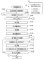
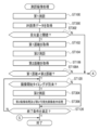
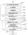
- It is a flowchart which shows an example of the flow of the distance measurement imaging process which concerns on 1st Embodiment. It is a continuation of the flowchart shown in FIG. 17A. It is a flowchart which shows the 1st modification of the flow of the distance measurement imaging process which concerns on 1st Embodiment.
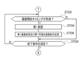
- FIG. 18A It is a continuation of the flowchart shown in FIG. 18A. It is a continuation of the flowchart shown in FIG. 18B. It is a flowchart which shows the 2nd modification of the flow of the distance measurement imaging process which concerns on 1st Embodiment. It is a flowchart which shows the 3rd modification of the flow of the distance measurement imaging process which concerns on 1st Embodiment. It is a flowchart which shows the 4th modification of the flow of the distance measurement imaging process which concerns on 1st Embodiment. It is a rear view perspective view which shows an example of the mode in which the smart device which concerns on 1st Embodiment further provided a wide-angle receiver.
- FIG. 27 It is a conceptual diagram which shows an example of the detail of the specific processing shown in FIG. 27. It is a flowchart which shows an example of the flow of the distance measurement imaging process which concerns on 2nd Embodiment. It is a continuation of the flowchart shown in FIG. 29A. It is a continuation of the flowchart shown in FIG. 29B. It is a conceptual diagram which shows an example of the mode in which the distance measurement image processing program which concerns on embodiment is installed in a smart device.
- CPU refers to the abbreviation of "Central Processing Unit”.
- RAM refers to the abbreviation of "Random Access Memory”.
- ASIC refers to the abbreviation of "Application Special Integrated Circuit”.
- PLD refers to the abbreviation of "Programmable Logical Device”.
- FPGA is "Field-Programmable Gate” It refers to the abbreviation of "Array”.
- SoC refers to the abbreviation of "System-on-a-chip”.
- SSD refers to the abbreviation of "Solid State Drive”.
- USB is the abbreviation of "Universal Serial Bus”.
- HDD refers to the abbreviation of "Hard Disk Drive”.
- EEPROM refers to the abbreviation of "Electricularly Erasable and Programmable Read Only Memory”.
- EL refers to the abbreviation of "Electro-Lumine”.
- / D refers to the abbreviation of "Analog / Digital”.
- I / F refers to the abbreviation of "Interface”.
- UI refers to the abbreviation of "User Interface”.
- LTE refers to "Long System Evolution”.
- 5G refers to the abbreviation of "5th Generation”.
- LD refers to the abbreviation of "Laser Audio”.
- IR refers to the abbreviation of "Infrared”.
- APD refers to "Avalanche”. It refers to the abbreviation of "Photodiode”.
- TOF is It refers to the abbreviation of "Time of Flight”.
- fps refers to the abbreviation of "frame per second”.
- LED refers to the abbreviation of "Light Emitting Diode”.
- ROI is an abbreviation for "Region of Interest”.
- LAN refers to the abbreviation of "Local Area Network”.
- AF refers to the abbreviation for "Auto Focus”.
- IC refers to the abbreviation of "Integrated Circuit”.
- horizontal refers to horizontal in the sense of including an error generally allowed in the technical field to which the technology of the present disclosure belongs, in addition to perfect horizontal.
- parallel refers to parallelism in the sense that it includes, in addition to perfect parallelism, errors that are generally acceptable in the art to which the techniques of the present disclosure belong.
- vertical refers to vertical in the sense of being perfectly vertical, as well as including errors that are generally tolerated in the art to which the technology of the present disclosure belongs.
- match refers to a match in the sense of including an error that is generally tolerated in the technical field to which the technology of the present disclosure belongs, in addition to the perfect match.
- the smart device 10 performs an imaging operation (hereinafter, also simply referred to as “imaging operation”) for imaging an imaging region defined by an angle of view ⁇ 1 and a distance measuring operation.
- imaging operation also simply referred to as “imaging operation”
- the “distance measurement” refers to a process of measuring the distance from the smart device 10 to the imaging region.
- the smart device 10 is an example of an "information processing device” according to the technology of the present disclosure, and examples of the smart device 10 include a smartphone or a tablet terminal which is an electronic device having an imaging function.
- the first distance measurement and the second distance measurement in which the distance measurement methods are different from each other are performed.
- the first distance measurement determines the distance to the imaging region based on the timing at which the smart device 10 irradiates the laser beam toward the imaging region and the timing at which the smart device 10 receives the reflected light from the imaging region of the laser beam. It is a distance measurement of a measuring method (hereinafter, also referred to as an "active method").
- the second distance measurement is a distance measurement of a method (hereinafter, also referred to as “passive method”) in which the distance to the imaging region is measured based on the image obtained by capturing the imaging region by the smart device 10. ..
- the image obtained by capturing the imaging region by the smart device 10 is an example of the "first image” according to the technique of the present disclosure.
- the laser beam is an example of "light” according to the technique of the present disclosure.
- the laser beam is surface-irradiated toward the imaging region.
- the surface irradiation refers to irradiation in which the beam diameter of the laser beam expands toward the imaging region as compared with the spot irradiation. In surface irradiation, the beam diameter of the laser beam gradually expands along the irradiation direction of the laser light, and the degree to which the beam diameter expands per unit time is larger in surface irradiation than in spot irradiation.
- the laser beam in the spot irradiation, the laser beam is irradiated in a dot shape on a surface having an imaging region, whereas in the surface irradiation, the laser beam is irradiated in a plane shape on a surface having an imaging region.
- the laser beam irradiation may be single-shot, but may be performed intermittently (for example, every 0.1 seconds). In this case, the first distance measurement is performed for each laser beam irradiation. It may be performed and processing based on the distance measurement result may be performed.
- a hybrid type distance measurement that combines an active type distance measurement and a passive type distance measurement is performed. Then, in the smart device 10, imaging with active focus control and imaging with passive focus control are performed.
- the active focus control refers to focus control based on the distance measurement result obtained by performing the active distance measurement.
- Passive focus control refers to focus control based on the distance measurement result obtained by performing passive distance measurement.
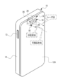
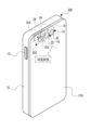
- the smart device 10 includes a housing 12.
- the distance measuring image pickup device 14 is housed in the housing 12.
- the distance measuring image pickup device 14 includes a light irradiator 16 and a light receiver 18.
- the light irradiator 16 includes an LD 24, and in the smart device 10, the imaging operation and the ranging operation are performed by the ranging imaging device 14.
- An instruction key 13 is arranged on the side surface of the smart device 10.
- the instruction key 13 receives various instructions.
- the "various instructions" referred to here are, for example, an instruction to display a menu screen on which various menus can be selected, an instruction to select one or more menus, an instruction to confirm the selected contents, and an instruction to delete the selected contents. Refers to instructions, etc.
- Translucent windows 20 and 22 are provided in the upper left portion of the back surface 12A of the housing 12 when the smart device 10 is placed vertically (the upper left portion of the rear view of the smart device 10 in the vertically installed state). ..
- the translucent windows 20 and 22 are optical elements (for example, lenses) having translucency, are arranged along the horizontal direction at predetermined intervals (for example, at intervals of several millimeters), and are exposed from the back surface 12A.
- the light irradiator 16 irradiates the laser beam emitted from the LD 24 toward the imaging region through the translucent window 20.
- the laser beam in the infrared wavelength region is irradiated toward the imaging region by the light irradiator 16.
- the wavelength range of the laser light is not limited to this, and may be laser light in another wavelength range.
- the receiver 18 takes in IR reflected light through the translucent window 22.
- the IR reflected light refers to the reflected light from the distance measuring target of the laser light irradiated to the distance measuring target by the light irradiator 16.
- the receiver 18 takes in visible reflected light through the translucent window 22.
- the visible reflected light refers to the reflected light from the imaging region of visible light (for example, visible light contained in sunlight) irradiated to the imaging region. In the following, for convenience of explanation, when it is not necessary to distinguish between IR reflected light and visible reflected light, they are simply referred to as “reflected light”.
- the receiver 18 is an example of an "imaging device” according to the technique of the present disclosure, and includes a photoelectric conversion element 26.
- the photoelectric conversion element 26 receives the reflected light taken into the light receiver 18 through the translucent window 22, and outputs an electric signal corresponding to the amount of the received reflected light.
- a touch panel display 59 is provided on the front surface 12B of the housing 12.
- the touch panel display 59 includes a display 46 and a touch panel 48.
- An example of the display 46 is an organic EL display.
- the display 46 may be another type of display such as a liquid crystal display instead of the organic EL display.
- the display 46 displays an image (for example, a live view image and a reproduced image), character information, and the like.
- the touch panel 48 is a transmissive touch panel and is superimposed on the surface of the display area of the display 46.
- the touch panel 48 receives an instruction from the user by detecting contact with an indicator such as a finger or a stylus pen.
- an out-cell type touch panel display in which the touch panel 48 is superimposed on the surface of the display area of the display 46 is mentioned, but this is only an example.
- an on-cell type or in-cell type touch panel display can be applied.
- the image pickup region is imaged by the receiver 18. That is, the receiver 18 receives the visible light reflected light and generates a visible light image showing the imaging region as an image corresponding to the received visible light reflected light.
- the visible light image is an example of the "first image” and the "second image” according to the technique of the present disclosure.
- the visible light image is displayed on the display 46 as a live view image or a still image according to the instruction received by the touch panel 48.
- the imaging region is defined by the angle of view ⁇ 1.
- the angle of view ⁇ 1 is changed according to the instruction received by the touch panel 48.
- the light irradiator 16 emits a laser beam. Is irradiated.
- the angle at which the laser beam is irradiated (hereinafter, also referred to as “irradiation angle”) is ⁇ 2, and the irradiation angle ⁇ 2 is changed according to the instruction received by the touch panel 48.
- irradiation angle The angle at which the laser beam is irradiated (hereinafter, also referred to as “irradiation angle”) is ⁇ 2, and the irradiation angle ⁇ 2 is changed according to the instruction received by the touch panel 48.
- a mode example is given in which distance measurement is started in response to a distance measurement imaging start instruction received by the touch panel 48 while the visible light image is displayed as a live view image on the display 46.
- the technique of the present disclosure is not limited to this.
- the distance measurement may be started when the touch panel 48 receives the distance measurement image start instruction while the visible light image is not displayed on the display 46.
- the distance from the smart device 10 to the distance measurement target is based on the time required from the irradiation of the laser beam by the light irradiator 16 to the reception of the IR reflected light by the receiver 18 and the speed of light.
- the distance is measured.
- the distance to the distance measurement target is set to "L 0 "
- the speed of light is set to "c”
- the time required from the irradiation of the laser beam by the light irradiator 16 to the reception of the IR reflected light by the light receiver 18 is calculated.
- the photoelectric conversion element 26 has a plurality of photodiodes arranged in a matrix.
- An example of the plurality of photodiodes is a photodiode for "4896 x 3265" pixels.
- a color filter is arranged on each photodiode included in the photoelectric conversion element 26.
- the color filters include a G filter corresponding to the G (green) wavelength region, an R filter corresponding to the R (red) wavelength region, a B filter corresponding to the B (blue) wavelength region, and a B filter corresponding to the B (blue) wavelength region, which contributes most to obtaining a brightness signal.
- the G filter, the R filter, and the B filter also have a function as an infrared light cut filter that cuts infrared light.
- the photoelectric conversion element 26 is formed by two types of photosensitive pixels, a retardation pixel and a non-phase difference pixel N, which is a pixel different from the retardation pixel. Generally, the non-phase difference pixel N is also referred to as a normal pixel.
- the photoelectric conversion element 26 has four types of photosensitive pixels as non-phase difference pixels: R pixel, G pixel, B pixel, and IR pixel.
- the R pixel, G pixel, B pixel, IR pixel, and retardation pixel are regularly arranged in each of the row direction (horizontal direction) and the column direction (vertical direction) with a predetermined periodicity.
- the R pixel is a pixel corresponding to the photodiode in which the R filter is arranged
- the G pixel and the phase difference pixel are the pixels corresponding to the photodiode in which the G filter is arranged
- the B pixel is the pixel in which the B filter is arranged.
- It is a pixel corresponding to the photodiode
- the IR pixel is a pixel corresponding to the photodiode in which the IR filter is arranged.
- An example of an IR pixel is InGaAs APD.
- a plurality of retardation pixel lines 26A and a plurality of non-phase difference pixel lines 26B are arranged on the light receiving surface of the photoelectric conversion element 26.
- the retardation pixel line 26A is a horizontal line including a retardation pixel.
- the phase difference pixel line 26A is a horizontal line in which phase difference pixels and non-phase difference pixels N are mixed.
- the non-phase difference pixel line 26B is a horizontal line including only a plurality of non-phase difference pixels N.
- the retardation pixel lines 26A and the non-phase difference pixel lines 26B corresponding to the predetermined number of lines are alternately arranged along the column direction.
- the "default number of lines" referred to here refers to, for example, two lines.
- 2 lines are illustrated as the default number of lines, but the technique of the present disclosure is not limited to this, and the default number of lines may be several lines of 3 or more lines, or more than 10 lines. , Dozens of lines, hundreds of lines, and the like.
- the phase difference pixel line 26A is arranged by skipping two rows in the column direction from the first row to the last row. Some pixels of the phase difference pixel line 26A are phase difference pixels. Specifically, the phase difference pixel line 26A is a horizontal line in which phase difference pixels and non-phase difference pixels N are periodically arranged. The phase difference pixel is roughly classified into a first phase difference pixel L and a second phase difference pixel R. In the phase difference pixel line 26A, first phase difference pixels L and second phase difference pixels R are alternately arranged as G pixels at intervals of several pixels in the line direction.
- the first phase difference pixel L and the second phase difference pixel R are arranged so as to appear alternately in the column direction.
- the first phase difference pixel L, the second phase difference pixel R, the first phase difference pixel L, and the second phase difference pixel R are arranged along the column direction from the first row. They are arranged in order. That is, the first phase difference pixel L and the second phase difference pixel R are alternately arranged along the column direction from the first row.
- the second phase difference pixel R, the first phase difference pixel L, the second phase difference pixel R, and the first phase difference pixel along the column direction from the first row are arranged in the order of L. That is, the second phase difference pixel R and the first phase difference pixel L are alternately arranged along the column direction from the first row.
- the photoelectric conversion element 26 is divided into three regions. That is, the photoelectric conversion element 26 has a visible light image division region 26N1, a first distance measurement system division region 26N2, and a second distance measurement system division region 26N3.
- the visible light image division region 26N1 is a group of visible light pixels composed of a plurality of visible light pixels, and is used for generating a visible light image.
- the first ranging system division region 26N2 is an IR pixel group consisting of a plurality of IR pixels, and is used for the first ranging.
- the second ranging system division region 26N3 is a phase difference pixel group consisting of a plurality of retardation pixels, and is used for the second ranging.
- the visible light image division region 26N1 and the second ranging system division region 26N3 receive visible reflected light and output an electric signal according to the amount of received light.
- the first ranging system division region 26N2 receives IR reflected light and outputs an electric signal according to the amount of received light.
- the first retardation pixel L includes a microlens 19, a light-shielding member 17A, and a photodiode PD.
- a light-shielding member 17A is arranged between the microlens 19 and the light-receiving surface of the photodiode PD.
- the left half of the light receiving surface of the photodiode PD in the row direction (the left side when facing the subject from the light receiving surface (in other words, the right side when facing the light receiving surface from the subject)) is shielded by the light shielding member 17A.
- the second phase difference pixel R includes a microlens 19, a light-shielding member 17B, and a photodiode PD.
- a light-shielding member 17B is arranged between the microlens 19 and the light-receiving surface of the photodiode PD.
- the right half of the light receiving surface of the photodiode PD in the row direction (the right side when facing the subject from the light receiving surface (in other words, the left side when facing the light receiving surface from the subject)) is shielded by the light shielding member 17B.
- the light shielding member 17B In the following, for convenience of explanation, when it is not necessary to distinguish between the light-shielding members 17A and 17B, they are referred to as "light-shielding members" without reference numerals.
- the luminous flux passing through the exit pupil of the image pickup lens 41 is roughly classified into left region passing light 300L and right region passing light 300R.
- the left region passing light 300L refers to the left half of the luminous flux passing through the exit pupil of the imaging lens 41 when facing the subject side from the phase difference pixel side
- the right region passing light 300R refers to the imaging lens 41.
- the luminous flux passing through the exit pupil of the above it refers to the luminous flux of the right half when facing the subject side from the phase difference pixel side.
- the luminous flux passing through the exit pupil of the imaging lens 41 is divided into left and right by the microlens 19, the light-shielding member 17A, and the light-shielding member 17B that function as the pupil dividing portion, and the first retardation pixel L is the light passing through the left region as the subject light.
- 300L is received
- the second phase difference pixel R receives the right region passing light 300R as the subject light.
- the photoelectric conversion element 26 generates a first phase difference image corresponding to the subject image corresponding to the left region passing light 300L and a second phase difference image corresponding to the subject image corresponding to the right region passing light 300R.
- the distance to the imaging region is measured based on the amount of deviation ⁇ between the first phase difference image for one line and the second phase difference image for one line. Will be done.
- the non-phase difference pixel N is different from the phase difference pixel in that it does not have a light-shielding member.
- the photodiode PD of the non-phase difference pixel N receives the left region passing light 300L and the right region passing light 300R as the subject light.
- the IR reflected light is received by each of the plurality of IR pixels included in the second ranging system division region 26N3 (see FIG. 5), so that the distance is measured for each IR pixel. Then, in the smart device 10, the distance measurement result for each IR pixel is displayed on the display 46 as a distance image according to the instruction received by the touch panel 48.
- the distance image refers to an image in which the distance to the distance measurement target measured for each IR pixel is expressed by color and / or shading.
- the distance measurement result is displayed on the display 46 as a distance image or a distance superimposition image according to the instruction received by the touch panel 48.
- the distance superimposed image displayed on the display 46 is, for example, an image in which a numerical value indicating a distance measurement result is superimposed on a visible light image (for example, a live view image).
- a visible light image for example, a live view image.
- the distances from the smart device 10 to each of a plurality of typical locations (for example, three locations) in the imaging region are displayed on the display 46 in a visible light image.
- a plurality of specific subjects in the imaging region for example, a subject included in the center region of the screen and / or a human being
- a contrast difference is equal to or greater than a default value. The part of is mentioned.
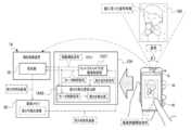
- the smart device 10 in addition to the light irradiator 16 and the receiver 18, the smart device 10 includes a controller 15, an input / output interface 40, an image memory 42, a UI device 44, an external I / F 52, and communication. It is equipped with an I / F 54.
- the controller 15 includes a CPU 15A, a storage 15B, and a memory 15C.
- the CPU 15A, the storage 15B, and the memory 15C are connected via the bus 50, and the bus 50 is connected to the input / output interface 40.
- one bus is shown as the bus 50 for convenience of illustration, but a plurality of buses may be used.
- the bus 50 may be a serial bus or a parallel bus including a data bus, an address bus, a control bus, and the like.
- the storage 15B stores various parameters and various programs.
- the storage 15B is a non-volatile storage device.
- a flash memory is adopted as an example of the storage 15B.
- the flash memory is merely an example, and examples of the storage 15B include various non-volatile memories such as a magnetoresistive memory and / or a ferroelectric memory instead of the flash memory or in combination with the flash memory. ..
- the non-volatile storage device may be EEPROM, HDD, and / or SSD or the like.
- the memory 15C temporarily stores various information and is used as a work memory.
- An example of the memory 15C is RAM, but the memory is not limited to this, and other types of storage devices may be used.
- the CPU 15A reads a necessary program from the storage 15B and executes the read program on the memory 15C.
- the CPU 15A controls the entire smart device 10 according to a program executed on the memory 15C.
- the storage 15B and the memory 15C are examples of the "memory" according to the technique of the present disclosure.
- a plurality of devices are connected to the input / output interface 40, and the input / output interface 40 controls the exchange of various information between the plurality of devices.
- a controller 15 As a plurality of devices connected to the input / output interface 40, a controller 15, a light irradiator 16, a receiver 18, an image memory 42, a UI device 44, an external I / F 52, and a communication I / F54 is shown.
- the external I / F 52 controls the exchange of various information with and from a device existing outside the smart device 10 (hereinafter, also referred to as an "external device").
- An example of the external I / F 52 is a USB interface.
- External devices such as smart devices, personal computers, servers, USB memory sticks, memory cards, and / or printers can be directly or indirectly connected to the USB interface.
- the communication I / F54 has communication functions such as LTE, 5G, wireless LAN, and / or Bluetooth (registered trademark), and controls the exchange of various information between the external device and the CPU 15A.
- the communication I / F 54 is communicably connected to the network 56 (for example, the Internet) via a base station (not shown), and various information is exchanged between the external device on the network 56 and the CPU 15A. Controls.
- the UI device 44 includes a display 46, and the CPU 15A causes the display 46 to display various information. Further, the UI device 44 includes a reception device 47.
- the reception device 47 includes a touch panel 48 and a hard key unit 53.
- the hard key unit 53 is at least one hard key including an instruction key 13 (see FIG. 2).
- the CPU 15A operates according to various instructions received by the touch panel 48.
- the hard key unit 53 is included in the UI device 44 here, the technique of the present disclosure is not limited to this, and for example, the hard key unit 53 may be connected to the external I / F 52. Good.
- the light irradiator 16 includes a transparent window 20, a beam expander 21, a collimating lens 23, an LD24, and an LD driver 25, and is transparent from the imaging region side (object side) to the LD24 along the optical axis L1.
- the light window 20, the beam expander 21, and the collimating lens 23 are arranged in this order.
- the LD driver 25 is connected to the LD 24 and the input / output interface 40, and drives the LD 24 according to the instruction of the CPU 15A to emit laser light from the LD 24.
- the laser light emitted from the LD 24 is converted into parallel light by the collimated lens 23, then the beam diameter is expanded by the beam expander 21, and the laser light is emitted from the translucent window 20 toward the distance measurement target.
- the light receiver 18 includes a translucent window 22, an objective lens 30A, a focus lens 30B, an aperture 30C, a photoelectric conversion element 26, a photoelectric conversion element driver 32, and a signal processing circuit 34.
- the CPU 15A and the signal processing circuit 34 are examples of the "processor" according to the technique of the present disclosure.
- the translucent window 22, the objective lens 30A, the focus lens 30B, and the aperture 30C are arranged in this order from the imaging region side (object side) to the photoelectric conversion element 26 along the optical axis L2.
- the photoelectric conversion element driver 32 is connected to the photoelectric conversion element 26 and the input / output interface 40, and drives the photoelectric conversion element 26 according to the instructions of the CPU 15A.
- the photoelectric conversion element driver 32 supplies the photoelectric conversion element 26 with an imaging timing signal that defines the timing of imaging performed by the photoelectric conversion element 26 under the control of the CPU 15A.
- the photoelectric conversion element 26 resets, exposes, and outputs an electric signal according to the imaging timing signal supplied from the photoelectric conversion element driver 32. Examples of the imaging timing signal include a vertical synchronization signal and a horizontal synchronization signal.
- the receiver 18 includes a focusing control mechanism 31.
- the focusing control mechanism 31 includes a focus lens 30B, a moving mechanism 60, a motor 62, and a motor driver 64.
- the focus lens 30B is slidably supported along the optical axis L2 by the moving mechanism 60.
- the motor 62 is connected to the moving mechanism 60 and the motor driver 64.
- the motor driver 64 is connected to the input / output interface 40 and drives the motor 62 according to an instruction from the CPU 15A.
- the moving mechanism 60 is connected to a drive shaft (not shown) of the motor 62, and receives power from the motor 62 to selectively move the focus lens 30B between the object side and the image side along the optical axis L2. Let me.
- the CPU 15A adjusts the focusing position by controlling the drive of the motor 62 via the motor driver 64.
- the "focus position" is the light of the focus lens 30B in a state of being in focus (for example, a state in which the contrast of the visible light image is maximized or a state in which a predetermined depth of field is achieved). Refers to the position on the axis L2.
- the control for aligning the focus lens 30B with the in-focus position is referred to as "focus control".
- the diaphragm 30C is a fixed diaphragm whose opening does not change. In the case of a fixed aperture, the exposure adjustment is performed by the electronic shutter of the photoelectric conversion element 26.
- the diaphragm 30C may be a variable diaphragm instead of a fixed diaphragm.
- the objective lens 30A, the focus lens 30B, and the diaphragm 30C included in the light receiver 18 are merely examples, and the technique of the present disclosure is established even if the configuration of the lens and / or the position of the diaphragm 30C is changed.
- Reflected light is incident on the receiver 18 from the translucent window 22.
- the reflected light incident on the translucent window 22 is imaged on the photoelectric conversion element 26 via the objective lens 30A, the focus lens 30B, and the diaphragm 30C.
- the photoelectric conversion element 26 is connected to the signal processing circuit 34, and outputs pixel data indicating a pixel value to the signal processing circuit 34 for each pixel of the visible light pixel and the IR pixel.
- the signal processing circuit 34 digitizes the pixel data by performing A / D conversion on the pixel data input from the photoelectric conversion element 26, and performs various signal processing on the digitized pixel data.
- the signal processing circuit 34 includes a visible light pixel data processing circuit 34A, a first ranging system processing circuit 34B, and a second ranging system processing circuit 34C.
- the visible light pixel data processing circuit 34A is known signal processing such as white balance adjustment, sharpness adjustment, gamma correction, color space conversion processing, and color difference correction for visible light pixel data which is pixel data for visible light pixels. Is applied to generate a visible light image. Then, the visible light pixel data processing circuit 34A stores the visible light image in the image memory 42. The visible light image in the image memory 42 is updated by overwriting and saving one frame of the visible light image in the image memory 42.
- the distance measuring image pickup device 14 includes a TOF camera 27.
- the TOF camera 27 includes a light irradiator 16, a first ranging system division region 26N2 (see FIG. 5) of the photoelectric conversion element 26, and a first ranging system processing circuit 34B.
- the first ranging system processing circuit 34B acquires an irradiation timing signal indicating an irradiation timing (hereinafter, also simply referred to as “irradiation timing”) in which the light irradiator 16 irradiates the laser beam toward the imaging region from the CPU 15A.
- the first distance measuring system processing circuit 34B is based on the irradiation timing indicated by the irradiation timing signal and the timing at which the IR reflected light is received by each IR pixel (hereinafter, also referred to as “light receiving timing”). The distance from the smart device 10 to the imaging region is measured.
- the light receiving timing the timing at which the IR pixel data having an output value exceeding the threshold value is received by the first ranging system processing circuit 34B is adopted.
- the threshold value used here is set in advance as an output value of a noise component (for example, a noise component generated independently of IR reflected light) output from IR pixels by, for example, a test using an actual machine and / or a computer simulation. It is a value derived from.
- the first distance measuring system processing circuit 34B measures the distance from the smart device 10 to the imaging region for each IR pixel based on the irradiation timing and the light receiving timing, and generates a distance image based on the measurement result for each IR pixel. Then, the generated distance image is stored in the image memory 42. The distance image in the image memory 42 is updated by overwriting and saving the distance image for one frame in the image memory 42.
- the second ranging system processing circuit 34C is a plurality of phase difference pixels of the second ranging system division region 26N3 (see FIG. 5) included in the region (so-called ROI) designated by the user or the like in the photoelectric conversion element 26. From each, the phase difference pixel data indicating the pixel value of the phase difference pixel is acquired. The second ranging system processing circuit 34C generates a first phase difference image and a second phase difference image (see FIG. 5) from the phase difference pixel data, and the generated first phase difference image and the second phase difference image are combined with each other. The deviation amount ⁇ (see FIG. 5) is calculated. Then, the second ranging system processing circuit 34C calculates the distance from the smart device 10 to the imaging region based on the calculated deviation amount ⁇ . Specifically, the second ranging system processing circuit 34C calculates the distance from the smart device 10 to the imaging region by using an arithmetic expression in which the deviation amount ⁇ is an independent variable and the distance is a dependent variable.
- the technique of the present disclosure is not limited to this, and the second ranging system processing circuit 34C is smart by using a table in which the deviation amount ⁇ and the distance are associated with each other. The distance from the device 10 to the imaging region may be derived.
- the CPU 15A acquires the distance measured by the first distance measuring system processing circuit 34B (hereinafter referred to as “first distance”) from the first distance measuring system processing circuit 34B, and measures it by the second distance measuring system processing circuit 34C.
- the obtained distance (hereinafter, referred to as “second distance”) is acquired from the second distance measuring system processing circuit 34C.
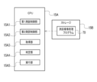
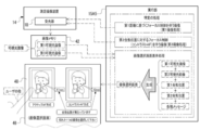
- the distance measuring image processing program 70 is stored in the storage 15B.
- the CPU 15A reads the distance measurement image processing program 70 from the storage 15B, and executes the read distance measurement image processing program 70 to execute the first distance measurement control unit 15A1, the second distance measurement control unit 15A2, the acquisition unit 15A3, and the determination unit. It operates as 15A4 and the execution unit 15A5.
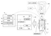
- the smart device 10 performs the first distance measurement on the imaging region including the entire mirror 100 in which the user is reflected (hereinafter, also referred to as “mirror-included imaging region”).
- the touch panel 48 receives the distance measurement image start instruction while the mirror-included image pickup area is contained in the irradiation angle ⁇ 2
- the first distance measurement control unit 15A1 sends the first distance measurement start signal to the light irradiator 38B and the receiver 18. Output to.
- the light irradiator 38B irradiates the laser beam when the first distance measurement start signal is input from the first distance measurement control unit 15A1.
- the first distance measurement system processing circuit 34B causes the irradiation timing and the light reception timing indicated by the irradiation timing signal acquired from the CPU 15A.
- the first distance is calculated based on.
- the acquisition unit 15A3 acquires the first distance from the first distance measuring system processing circuit 34B.
- the first distance is an example of the "first distance measurement result" according to the technique of the present disclosure.
- the irradiation timing the timing when a predetermined time elapses from the timing when the first distance measurement start signal is input to the receiver 18 from the first distance measurement control unit 15A1 is adopted.
- the predetermined time is, for example, the time required from the time when the first ranging start signal is output until the laser beam is irradiated from the light irradiator 38B, which is derived in advance by a test using an actual machine and / or a computer simulation or the like. Time was given.
- the second distance measurement control unit 15A2 When the touch panel 48 receives the distance measurement image start instruction while the mirror-included image pickup area is contained in the angle of view ⁇ 1, the second distance measurement control unit 15A2 outputs the second distance measurement start signal to the receiver 18.
- the second distance measurement start signal is input from the second distance measurement control unit 15A2 to the receiver 18, the second distance measurement system division area 26N3 images the mirror-included image pickup area and positions according to the mirror inclusion image pickup area.
- the phase difference pixel data is output to the second ranging system processing circuit 34C.
- the second ranging system processing circuit 34C generates a first retardation image and a second retardation image (see FIG. 6) based on the phase difference pixel data input from the second ranging system division region 26N3, and generates them.
- the deviation amount ⁇ (see FIG. 6) is calculated based on the first phase difference image and the second phase difference image.
- the second distance measuring system processing circuit 34C calculates the second distance from the calculated deviation amount ⁇ .
- the acquisition unit 15A3 acquires the second distance from the second ranging system processing circuit 34C.
- the second distance is an example of the "second distance measurement result" according to the technique of the present disclosure.
- the distance measurement result obtained by performing the first distance measurement by the smart device 10 with respect to the mirror-included imaging region that is, the first distance is obtained from the smart device 10 to the mirror 100.
- the distance measurement result obtained by performing the second distance measurement by the smart device 10 with respect to the mirror-included imaging region that is, the second distance is from the smart device 10 to the subject image reflected in the mirror 100.
- the distance In the example shown in FIG. 12, the image of the smart device 10 (“smart device image” in the example shown in FIG. 12) and the image of the user (in the example shown in FIG. 12, “user”) are the subject images reflected in the mirror 100.
- the image ”) is shown, and the second distance is the distance from the smart device 10 to the user image.
- the smart device 10 when the user wants to take an image of the entire mirror 100 as a subject by using the smart device 10, the smart device 10 performs focus control based on the second distance to take an image of the entire mirror 100. An image is obtained in a state where the mirror 100 is out of focus.
- the smart device 10 when the user wants to take an image of the user image reflected in the mirror 100 as a subject by using the smart device 10, the smart device 10 performs focus control based on the first distance to take an image of the user image. , An image is obtained in a state where the user image is out of focus.
- the determination unit 15A4 and the execution unit 15A5 operate as shown in FIG. 13 as an example.
- the determination unit 15A4 determines whether or not the first distance (see FIG. 10) and the second distance (see FIG. 11) acquired by the acquisition unit 15A3 are different.
- the execution unit 15A5 performs the first imaging process. ..
- the first imaging process refers to imaging with focus control based on the first distance.
- the focus position derivation table 72 is stored in the storage 15B.
- the distance from the smart device 10 to the imaging region and the focusing position are associated with each other.
- the execution unit 15A5 derives the focusing position corresponding to the first distance from the focusing position derivation table 72, and the light receiver 18 moves the focus lens 30B to the derived focusing position.
- the motor 62 is controlled.
- the visible light image division region 26N1 of the receiver 18 is controlled by the execution unit 15A5, so that the image pickup region is imaged by the visible light image division region 26N1 and the visible light pixel data obtained by the imaging is performed.
- the visible light pixel data processing circuit 34A generates a first visible light image indicating an imaging region based on the visible light pixel data input from the visible light image division region 26N1, and images the generated first visible light image. Output to memory 42.
- the first visible light image is stored in the image memory 42.
- the execution unit 15A5 performs a specific process.
- a specific process is a process including, for example, a first image pickup process, a second image pickup process, and an image selection screen display process.
- the second imaging process refers to imaging with focus control based on the second distance.
- the execution unit 15A5 derives the focusing position corresponding to the second distance from the focusing position derivation table 72, and moves the focus lens 30B to the derived focusing position.
- the motor 62 of the receiver 18 is controlled so as to cause the light receiver 18.
- the imaging region is imaged by the visible light image division region 26N1, and the visible light pixel data obtained by the imaging is the visible light pixel data processing from the visible light image division region 26N1. It is output to the circuit 34A.
- the visible light pixel data processing circuit 34A generates a second visible light image indicating an imaging region based on the visible light pixel data input from the visible light image division region 26N1, and images the generated second visible light image. Output to memory 42.
- the second visible light image is stored in the image memory 42.
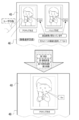
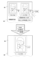
- the execution unit 15A5 acquires the first visible light image and the second visible light image from the image memory 42. Then, the execution unit 15A5 has a first visible light image, a second visible light image, a first distance acquired by the acquisition unit 15A3 (see FIG. 10), and a second distance acquired by the acquisition unit 15A3 (FIG. 10). 11) and various messages, an image selection screen is generated, and the generated image selection screen is displayed on the display 46. The first visible light image and the second visible light image are displayed side by side on the image selection screen. Further, the message "active method" is displayed below the first visible light image.
- the message "active method” is a message indicating that the first visible light image is an image obtained by imaging with focus control based on the distance measurement result by the active method distance measurement (first distance measurement). Further, the message “passive method” is displayed below the second visible light image. The message “passive method” is a message indicating that the second visible light image is an image obtained by imaging with focus control based on the distance measurement result by the passive method distance measurement (second distance measurement).
- the first imaging process, the second imaging process, and the image selection screen display process are exemplified as the processes included in the specific process, but the technique of the present disclosure is limited to this. Instead, it may be one or two of the first imaging process, the second imaging process, and the image selection screen display process. Further, in the first embodiment, the display examples of "active method” and “passive method” are shown, but the display does not necessarily have to be “active method” and “passive method", and the user can use the distance measuring method. Any display may be used as long as the difference between the two can be understood.
- a display of "laser” and a display of "phase difference” may be displayed, or an icon or the like indicating a distance measurement method may be displayed.
- the focus position may be displayed instead of the distance measurement method display. For example, “focus position: front” and “focus position: back” may be displayed, or “focus position: object” and “focus position: image reflected on the object” may be displayed.
- two or more characters and icons indicating the distance measuring method and the focus position may be displayed in combination.
- the first visible light image is displayed in association with the numerical value "1.8 m” which is the result of the distance measurement by the first distance measurement
- the second visible light image is displayed by the second distance measurement.
- the numerical value "2.5 m" which is the result of distance measurement, is displayed in association with each other.
- a message "The distance measurement result is different” indicating that the distance measurement result by the first distance measurement and the distance measurement result by the second distance measurement are different is also displayed. Then, as a message prompting the user to select either the first visible light image or the second visible light image, the message "Please select one of the images" is displayed. ..
- the present invention is not limited to this, and various messages may be output by voice in parallel with the visible display.
- the image selection screen is displayed on the display 46, the user selects a first visible light image or a second visible light image via the touch panel 48.
- a mode in which the first visible light image is selected by the user's finger via the touch panel 48 is shown.
- the first visible light image is an example of the "first in-focus image” according to the technique of the present disclosure
- the second visible light image is an example of the "second in-focus image” according to the technique of the present disclosure. is there.
- the first distance measuring control unit 15A1 By controlling the distance measuring image pickup device 14, the first distance measuring system processing circuit 34B is made to perform the first distance measuring.
- the execution unit 15A5 executes the first imaging process and the first visible light image display process.
- the execution unit 15A5 executes the first imaging process using the new first distance obtained by performing the first distance measurement.
- the first visible light image display process is a process for displaying the latest first visible light image obtained by executing the first imaging process on the display 48.
- the first distance measurement and the first imaging process are performed again, and the latest first visible image obtained by performing the first imaging process is performed.
- An example of a form in which an optical image is displayed on the display 48 is given, but this is only an example.
- the selected first visible light image may be stored in a storage medium such as a storage 15B and / or a memory card on condition that the first visible light image is selected.
- the reception device 47 performs imaging with focus control based on the distance measured by the selected distance measuring method and storage of the selected image (for example, a first visible light image or a second visible light image). It may be selected according to the received instruction (instruction given by the user).
- the first visible light image display process is executed by the execution unit 15A5, the second visible light image, the numerical value "2.5 m”, the message “passive method”, and the “distance measurement result” are displayed in the image selection screen.
- the message “Different” and the message “Please select one of the images” are hidden from the screen.
- the first distance (a numerical value of "1.8 m” in the example shown in FIG. 15), which is the latest distance measurement result obtained by performing the latest first distance measurement, is displayed on the display 46, and the first distance is displayed. 1
- the first visible light image obtained by executing the imaging process is displayed on the display 46, and the message “active method” is also displayed below the first visible light image.
- the display area of the first distance, the first visible light image, and the message “active method” is from the display area of the first distance, the first visible light image, and the message “active method” in the image selection screen. Has also been expanded.
- the second ranging control unit 15A2 By controlling the distance measuring image pickup device 14, the second distance measuring system processing circuit 34C is made to perform the second distance measuring.
- the execution unit 15A5 executes the second imaging process and the second visible light image display process.
- the execution unit 15A5 executes the second imaging process using the new second distance obtained by performing the second distance measurement.
- the second visible light image display process is a process of displaying the latest second visible light image obtained by executing the second imaging process on the display 48.
- the second visible light image display process When the second visible light image display process is executed by the execution unit 15A5, the first visible light image, the numerical value “1.8 m”, the message “active method”, and the “distance measurement result” are displayed in the image selection screen. The message “Different” and the message “Please select one of the images” are hidden from the screen. Then, the second distance (a numerical value of "2.5 m” in the example shown in FIG. 16), which is the latest distance measurement result obtained by performing the latest second distance measurement, is displayed on the display 46, and the second distance is displayed. The second visible light image obtained by executing the two imaging processes is displayed on the display 46, and the message “passive method” is also displayed below the second visible light image. Further, the display area of the second distance, the second visible light image, and the message “passive method” is from the display area of the second distance, the second visible light image, and the message “passive method” in the image selection screen. Has also been expanded.
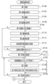
- FIGS. 17A and 17B are flowcharts showing an example of the flow of the distance measuring image processing executed by the CPU 15A according to the distance measuring image processing program 70.
- the first range-finding control unit 15A1 controls the range-finding imaging device 14 to perform the first measurement with respect to the first range-finding system processing circuit 34B. Let the distance be done.
- the first distance measurement is realized by having the first distance measurement control unit 15A1 calculate the first distance by the first distance measurement system processing circuit 34B.
- the acquisition unit 15A3 acquires the first distance obtained by performing the first distance measurement in step ST100.
- the second ranging control unit 15A2 controls the ranging imaging device 14 to cause the second ranging system processing circuit 34C to perform the second ranging.
- the second distance measurement is realized by having the second distance measurement control unit 15A2 calculate the second distance by the second distance measurement system processing circuit 34C.
- the acquisition unit 15A3 acquires the second distance obtained by performing the second distance measurement in step ST104.
- step ST108 the determination unit 15A4 determines whether or not the first distance acquired in step ST102 and the second distance acquired in step ST106 are different. In step ST108, if the first distance acquired in step ST102 and the second distance acquired in step ST106 match, the determination is denied and the ranging imaging process proceeds to step 120. In step ST108, if the first distance acquired in step ST102 and the second distance acquired in step ST106 are different, the determination is affirmed and the distance measuring imaging process shifts to step ST110.
- step ST110 the execution unit 15A5 executes the first imaging process using the first distance acquired in step ST102.
- the execution unit 15A5 executes the second imaging process using the second distance acquired in the step ST106.
- the execution unit 15A5 executes the image selection screen display process.
- the image selection screen is displayed on the display 46.
- step ST116 the execution unit 15A5 determines whether or not any of the first visible light image and the second visible light image displayed in the image selection screen is selected by the user via the touch panel 48. judge. In step ST116, if either the first visible light image or the second visible light image displayed in the image selection screen is not selected by the user via the touch panel 48, the determination is denied and the determination is denied. The determination in step ST116 is performed again. In step ST116, when either the first visible light image or the second visible light image displayed in the image selection screen is selected by the user via the touch panel 48, the determination is affirmed and the measurement is performed. The distance imaging process proceeds to step ST118.
- step ST118 the execution unit 15A5 determines whether or not the image selected from the image selection screen is the first visible light image. In step ST118, if the image selected from the image selection screen is the second visible light image, the determination is denied, and the distance measurement imaging process proceeds to step 130 shown in FIG. 17B. In step ST118, when the image selected from the image selection screen is the first visible light image, the determination is affirmed, and the ranging imaging process proceeds to step ST120.
- the imaging start timing refers to, for example, the timing at which imaging for one frame defined by the frame rate for a live view image is started. For example, if the frame rate for the live view image is 60 fps, the imaging start timing is every 1/60 second.
- the timing of starting the imaging for one frame defined by the frame rate for the live view image is illustrated as the imaging start timing, but the technique of the present disclosure is not limited to this.
- the imaging start timing may be the timing for starting imaging for one frame defined by the frame rate for the recorded moving image, or the reception device 47 receives an instruction to start imaging for the still image. It may be the timing.
- step ST120 If the imaging start timing has not arrived in step ST120, the determination is denied and the distance measurement imaging process shifts to step ST126.
- the imaging start timing arrives in step ST120, the determination is affirmed, and the distance measurement imaging process shifts to step ST122.
- step ST122 the first ranging control unit 15A1 controls the ranging imaging device 14 to cause the first ranging system processing circuit 34B to perform the first ranging.
- the execution unit 15A5 executes the first imaging process using the first distance obtained by performing the first distance measurement in step ST122.
- the execution unit 15A5 executes the first visible light image display processing using the latest first visible light image obtained by executing the first imaging process.
- the execution unit 15A5 determines whether or not the condition for ending the ranging imaging process (hereinafter, referred to as "end condition") is satisfied.
- end condition there is a condition that the instruction to end the distance measurement imaging process is received by the reception device 47. If the end condition is not satisfied in step ST126, the determination is denied and the ranging imaging process shifts to step ST120. If the end condition is satisfied in step ST126, the determination is affirmed and the distance measurement imaging process ends.
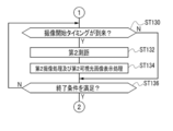
- step ST130 shown in FIG. 17B the execution unit 15A5 determines whether or not the imaging start timing has arrived. If the imaging start timing has not arrived in step ST130, the determination is denied and the ranging imaging process shifts to step ST136. When the imaging start timing arrives in step ST130, the determination is affirmed, and the distance measurement imaging process shifts to step ST132.
- step ST132 the second ranging control unit 15A2 controls the ranging imaging device 14 to cause the second ranging system processing circuit 34C to perform the second ranging.
- the execution unit 15A5 executes the second imaging process using the second distance obtained by performing the second distance measurement in step ST132.
- the execution unit 15A5 executes the second visible light image display processing using the latest second visible light image obtained by executing the second imaging process.
- step ST136 the execution unit 15A5 determines whether or not the end condition is satisfied. If the end condition is not satisfied in step ST136, the determination is denied and the ranging imaging process shifts to step ST130. If the end condition is satisfied in step ST136, the determination is affirmed and the distance measurement imaging process ends.
- the execution unit A specific process is performed by 15A5. Therefore, according to this configuration, it is possible to contribute to solving various problems that occur when the first distance and the second distance are different.
- the smart device 10 distance measurement is performed using laser light as directional light, which is directional light. Therefore, according to this configuration, the distance to the distance measurement target existing at a long distance can be measured with high accuracy as compared with the case where the distance measurement is performed without using the directional light.
- the image selection screen display process is executed by the execution unit 15A5 as a specific process.
- Information that notifies the user that the first distance and the second distance are different on the image selection screen displayed on the display 46 by executing the image selection screen display process by the execution unit 15A5 for example, the first distance.
- a numerical value indicating, a numerical value indicating the second distance, and a message) are included. Therefore, according to this configuration, the user can be made to recognize that the first distance and the second distance are different.
- the first imaging process and the second imaging process are executed by the execution unit 15A5. That is, the execution unit 15A5 causes the light receiver 18 of the distance measuring image pickup device 14 to perform imaging with focus control based on the first distance, and performs imaging with focus control based on the second distance. It is performed on the receiver 18 of 14. Therefore, according to this configuration, it is possible to make it easier to obtain an image in the focused state intended by the user as compared with the case where the image is taken under the focus control based on the first distance or the second distance.
- the first visible light image obtained by performing imaging under focus control based on the first distance and the first visible light image obtained by performing imaging under focus control based on the second distance are obtained.
- An image selection screen including the second visible light image is displayed on the display 46. Then, on the image selection screen, a message prompting the user to select the first visible light image or the second visible light image is displayed. Therefore, according to this configuration, it is possible to contribute to the improvement of usability as compared with the case where there is no room for selecting the first visible light image and the second visible light image.
- the execution unit 15A5 prompts the user to select the first visible light image or the second visible light image through the image selection screen, but the technique of the present disclosure is not limited to this.
- Both the first visible light image and the second visible light image may be selected.
- the first imaging process and the second imaging process are alternately performed, and each of the first visible light image and the second visible light image obtained by performing each imaging process is a live view image or a live view image. It may be displayed on the display 46 as a still image or the like.
- a plurality of images including the first visible light image and the second visible light image may be selectably displayed on the image selection screen. Further, when a plurality of first distances are obtained by the first distance measurement, a plurality of first visible light images obtained by performing imaging under focus control based on each of the plurality of first distances are image-selected.
- the display 46 may be displayed in a selectable state on the screen, or a plurality of first visible light images and a second visible light image may be displayed in a selectable state.
- the imaging region includes the first mirror surface and the second mirror surface (two mirror surfaces) (when there are two regions in which the first distance measurement result and the second distance measurement result are different)
- At least two of the images obtained by capturing the two images may be displayed on the display 46 in a selectable state.
- the number of mirror surfaces included in the imaging region is not limited to two, and may be three or more.
- an image may be reflected on a glossy surface (for example, a surface coated with silver plating or a polished metal surface). Also in this case, it is obtained by taking an image obtained by taking an image in a state where the glossy surface is in focus and an image in the glossy surface in a state where the image reflected on the glossy surface is in focus. The image may be selectively displayed on the display 46.
- the number of glossy surfaces included in the imaging region may be a plurality, but in this case as well, the same processing may be performed.
- the first visible light image or the second visible light image is selected by the user from the image selection screen via the touch panel 48.
- the techniques of the present disclosure are not limited to this.
- active distance measurement that is, imaging with focus control based on the distance measurement result by the first distance measurement
- passive distance measurement that is, the second distance measurement.
- the user may select in advance which of the imaging with the focus control based on the distance measurement result by the distance measurement is prioritized.
- the distance measurement imaging process shown in FIGS. 18A to 18C is executed by the CPU 15A instead of the distance measurement imaging process (see FIGS. 17A and 17B) described in the first embodiment.
- the distance-finding imaging processes shown in FIGS. 18A to 18C are different from the distance-finding imaging processes described in the first embodiment in that the processes of steps ST200 to ST222 are newly added. Further, the distance-finding imaging processes shown in FIGS. 18A to 18C are different from the distance-finding imaging processes described in the first embodiment in that they do not have the processes of steps ST110 to ST118. Further, the distance measuring imaging process shown in FIGS.
- 18A to 18C has the processing of steps ST224 and ST226 instead of the processing of steps ST132 and ST134, as compared with the distance measuring imaging process described in the first embodiment. The point is different.
- the distance measuring imaging process shown in FIGS. 18A to 18C will be described as being different from the distance measuring imaging process described in the first embodiment.
- step ST200 the execution unit 15A5 causes the display 46 to display the distance measurement method reception screen.
- the user is allowed to select whether to preferentially use active distance measurement, that is, first distance measurement or passive distance measurement, that is, second distance measurement.
- a message is displayed. In the example shown in FIG. 18A, the message "Please select which distance measurement method should be used with priority" is displayed on the distance measurement method reception screen.
- two softkeys are displayed on the distance measurement reception screen.
- One softkey is a softkey pressed by the user via the touch panel 48 when the user selects to preferentially use the active method of distance measurement, and is expressed as "active method” in the example shown in FIG. 18A. Has been done.
- the other softkey is a softkey pressed by the user via the touch panel 48 when the user selects to preferentially use the passive type distance measurement, and is expressed as "passive type" in the example shown in FIG. 18A. Has been done.
- the execution unit 15A5 determines whether or not an instruction from the user for the distance measurement method reception screen has been received.
- the "instruction from the user to the distance measurement method reception screen” means that the soft key described as “active method” or the soft key described as “passive method” is pressed by the user via the touch panel 48. It means that it was done. If the instruction from the user to the distance measurement method reception screen is not received in step ST202, the determination is denied and the determination in step ST202 is performed again. When an instruction from the user for the distance measuring method reception screen is received in step ST202, the determination is affirmed, and the distance measuring imaging process proceeds to step ST204.
- step ST204 the execution unit 15A5 determines whether or not the softkey pressed by the user via the touch panel 48 is the softkey described as "active method”. In step ST204, if the softkey pressed by the user via the touch panel 48 is the softkey described as "active method”, the determination is affirmed and the ranging imaging process proceeds to step ST100. In step ST204, if the softkey pressed by the user via the touch panel 48 is a softkey described as "passive method", the determination is denied and the ranging imaging process is performed in step ST206 shown in FIG. 18B. Move to.
- steps ST206 to ST212 shown in FIG. 18B is the same as the processing of steps ST100 to ST106 shown in FIG. 18A.
- the determination unit 15A4 determines whether or not the first distance acquired in step ST208 and the second distance acquired in step ST212 are different.
- the determination is denied and the distance measurement imaging process proceeds to step ST130 shown in FIG. 18C. Transition.
- the determination is affirmed and the distance measuring imaging process shifts to step ST216.
- step ST216 the execution unit 15A5 determines whether or not the imaging start timing has arrived. If the imaging start timing has not arrived in step ST216, the determination is denied and the ranging imaging process shifts to step ST222. When the imaging start timing arrives in step ST216, the determination is affirmed, and the distance measurement imaging process shifts to step ST218.
- step ST2128 the execution unit 15A5 executes the same process as the process in step ST132 shown in FIG. 17B, and in the next step ST220, the execution unit 15A5 executes the same process as the process in step ST134 shown in FIG. 17B. To do.
- the execution unit 15A5 determines whether or not the end condition is satisfied. If the end condition is not satisfied in step ST222, the determination is denied and the ranging imaging process shifts to step ST216. If the end condition is satisfied in step ST222, the determination is affirmed and the distance measurement imaging process ends.
- step ST130 shown in FIG. 18C if the imaging start timing has not arrived, the determination is denied and the distance measurement imaging process shifts to step ST136. In step ST130 shown in FIG. 18C, when the imaging start timing has arrived, the determination is affirmed, and the distance measurement imaging process shifts to step ST224.
- step ST224 the first ranging control unit 15A1 controls the ranging imaging device 14 to cause the first ranging system processing circuit 34B to perform the first ranging.
- the execution unit 15A5 executes the first imaging process using the first distance obtained by performing the first distance measurement in step ST224.
- the execution unit 15A5 executes the first visible light image display processing using the latest first visible light image obtained by executing the first imaging process.
- step ST136 shown in FIG. 18C If the end condition is not satisfied in step ST136 shown in FIG. 18C, the determination is denied and the ranging imaging process shifts to step ST130 shown in FIG. 18C. If the end condition is satisfied in step ST136 shown in FIG. 18C, the determination is affirmed and the distance measurement imaging process ends.
- step ST204 shown in FIG. 18A when the determination is affirmed in step ST204 shown in FIG. 18A and the determination is affirmed in step ST108 shown in FIG. 18A, the execution unit 15A5 performs the first distance measurement in step ST122 shown in FIG. 18A. Will be done. Then, in step ST124 shown in FIG. 18A, the first imaging process is performed using the first distance obtained by performing the first distance measurement in step ST122. That is, in step ST124 shown in FIG. 18A, imaging with focus control based on the first distance obtained by performing the first distance measurement in step ST122 is performed.
- step ST204 shown in FIG. 18A when the determination is denied in step ST204 shown in FIG. 18A and the determination is affirmed in step ST214 shown in FIG. 18B, the execution unit 15A5 performs the second distance measurement in step ST218 shown in FIG. 18B. .. Then, in step ST220 shown in FIG. 18B, the second imaging process is performed using the second distance obtained by performing the second distance measurement in step ST218. That is, in step ST220 shown in FIG. 18B, imaging with focus control based on the second distance obtained by performing the second distance measurement in step ST218 is performed.
- the first distance obtained by performing the first distance measurement and the second distance obtained by performing the second distance measurement are different.
- the power consumption required for focus control and imaging should be reduced as compared with the case where imaging is always performed under focus control based on the first distance and imaging is performed under focus control based on the second distance. Can be done.
- step ST124 shown in FIG. 18A.
- focus control is performed based on the first distance.
- the second imaging process in step ST220 shown in FIG. 18B focuses on the second distance. Control is done. That is, the focus control is performed based on any of the first distance and the second distance, which is determined according to the instruction given by the user.
- the focus control intended by the user can be easily realized as compared with the case where the focus control is not performed based on the instruction given by the user. ..
- the technique of the present disclosure is not limited to this.
- the instruction given by an external device for example, a personal computer and / or a server
- the external device may selectively give the smart device 10 an active distance measurement instruction and a passive distance measurement instruction according to the time zone and / or the weather. ..
- the external device selectively gives an active distance measurement instruction and a passive distance measurement instruction to the smart device 10 according to the time zone, for example, at night, the active distance measurement instruction is given. Is given to the smart device 10, and in the daytime, a passive distance measuring instruction may be given to the smart device 10. Further, when the external device selectively gives an active type distance measurement instruction and a passive type distance measurement instruction to the smart device 10 according to the weather, for example, when the weather is sunny, the passive type distance measurement is performed.
- the instruction may be given to the smart device 10, and the smart device 10 may be instructed to perform an active distance measurement when the weather is not sunny.
- the external device may give an active distance measurement instruction to the smart device 10 at night and when the weather is not sunny, or a passive system when it is daytime and the weather is sunny.
- the smart device 10 may be instructed to measure the distance.
- step ST200 in the case where the external device gives an instruction to the smart device 10 without the user giving an instruction, for example, in the distance measurement imaging process shown in FIG. 18A, the process of step ST200 becomes unnecessary, and in step ST202, Whether or not an instruction is given from the external device may be determined by the execution unit 15A5.
- the ranging imaging process shown in FIG. 19 may be executed by the CPU 15A.
- the distance measurement imaging process shown in FIG. 19 is different from the distance measurement imaging process shown in FIGS. 17A and 17B in that steps ST300 and ST302 are provided between steps ST100 and ST102. Further, the distance-finding imaging process shown in FIG. 19 is different from the distance-finding imaging process shown in FIGS. 17A and 17B in that it does not have steps ST110 to ST118. Further, the distance measurement imaging process shown in FIG. 19 is different from the distance measurement imaging process shown in FIGS. 17A and 17B in that it has step ST108A instead of step ST108. Further, the distance-finding imaging process shown in FIG. 19 is different from the distance-finding imaging process shown in FIGS. 17A and 17B in that it has steps ST304 and ST306 instead of steps ST122 and ST124.
- the distance measuring imaging process shown in FIG. 19 will be described as being different from the distance measuring imaging process described in the first embodiment.
- step ST300 shown in FIG. 19 the acquisition unit 15A3 processes the IR pixel data as the data indicating the amount of received IR reflected light received by the first ranging system division region 26N2 (see FIG. 5). Obtained from circuit 34B.
- the IR pixel data for each IR pixel included in the ROI of the first ranging system division region 26N2 is acquired by the acquisition unit 15A3.
- the determination unit 15A4 refers to the IR pixel data acquired in step ST300, and among the IR pixels included in the ROI of the first range-finding system division area 26N2, the IR pixel data is It is determined whether or not the light receiving amount of the IR pixel showing the maximum light receiving amount is equal to or more than the threshold value.
- the smart device 10 irradiates a mirror surface arranged at a predetermined distance (for example, several tens of meters) with a laser beam, and the laser beam is reflected by the mirror surface.
- a predetermined distance for example, several tens of meters
- the light receiving amount when the IR reflected light thus obtained is received by the IR pixels.
- a value derived in advance by a test with an actual machine and / or a computer simulation or the like is adopted.
- a mirror surface is illustrated as the irradiation destination of the laser beam, but the present invention is not limited to this, and a surface having a lower reflectance than the mirror surface may be used. Examples of the surface having a lower reflectance than the mirror surface include a glass surface, a surface of a translucent plastic plate-shaped member, and a surface having glossiness.
- step ST302 if the amount of received light is less than the threshold value, the determination is denied, and the distance measurement imaging process proceeds to step ST130 shown in FIG. 18C. If the amount of received light is equal to or greater than the threshold value in step ST302, the determination is affirmed, and the ranging imaging process shifts to step ST102.
- step ST108A the determination unit 15A4 determines whether or not the first distance acquired in step ST102 and the second distance acquired in step ST106 are different. In step ST108A, if the first distance acquired in step ST102 and the second distance acquired in step ST106 match, the determination is denied and the distance measurement imaging process proceeds to step ST130 shown in FIG. 18C. Transition. In step ST108A, if the first distance acquired in step ST102 and the second distance acquired in step ST106 are different, the determination is affirmed and the distance measuring imaging process shifts to step ST120.
- step ST304 the second ranging control unit 15A2 controls the ranging imaging device 14 to cause the second ranging system processing circuit 34C to perform the second ranging.
- the execution unit 15A5 executes the second imaging process using the second distance obtained by performing the second distance measurement in step ST304. That is, the execution unit 15A5 performs focus control based on the second distance obtained by performing the second distance measurement in step ST304, and causes the photoelectric conversion element 26 to perform imaging. In addition, the execution unit 15A5 executes the second visible light image display processing using the latest second visible light image obtained by executing the second imaging process.
- the focus control is performed based on the second distance, and thus IR.
- the user It is possible to facilitate imaging in an intended focused state (for example, imaging in a state where a portion different from the mirror 100 is in focus).
- the determination unit 15A4 determines whether or not the first distance and the second distance are different regardless of whether or not the imaging region includes a specific subject.
- the technology of the present disclosure is not limited to this.
- the determination unit 15A4 may determine whether or not the first distance and the second distance are different on the condition that the imaging region includes a specific subject.
- the distance measurement imaging process shown in FIG. 20 is executed by the CPU 15A.
- the distance-finding imaging process shown in FIG. 20 is different from the distance-finding imaging process described in the first embodiment in that step ST350 and step ST352 are provided between steps ST106 and ST108. Further, the distance-finding imaging process shown in FIG. 20 is different from the distance-finding imaging process described in the first embodiment in that it has step ST108B instead of step ST108. Further, the distance-finding imaging process shown in FIG. 20 is different from the distance-finding imaging process described in the first embodiment in that it has steps ST354 and ST356 instead of steps ST122 and ST124.
- the distance measuring imaging process shown in FIG. 20 will be described as being different from the distance measuring imaging process described in the first embodiment.
- the execution unit 15A5 executes the specific subject detection process.
- the specific subject detection process the light receiver 18 is subjected to focus control based on the first distance acquired in step ST102 to image the imaging region, and the imaging region image obtained by imaging the imaging region is performed.
- it is a process of detecting a specific subject image indicating a specific subject.
- the image in the imaging region is an example of the "second image" according to the technique of the present disclosure.
- the specific subject includes a high reflectance region having a predetermined reflectance or more. Examples of the default reflectance include a predetermined reflectance as the average reflectance of a glossy surface.
- a mirror surface 100A is adopted as the high reflectance region. Further, a user image and a smart device image are reflected on the mirror surface 100A.
- a specific subject image is detected for the imaged area image obtained by performing focus control based on the first distance acquired in step ST102 to image the imaged area.
- the disclosed technology is not limited to this.
- a specific subject image may be detected for an image obtained by performing focus control based on the second distance acquired in step ST106 to image an imaging region.
- the execution unit 15A5 detects a specific subject image with respect to the imaging region image by using a machine learning algorithm (for example, a neural network). Further, the execution unit 15A5 may detect a specific subject image with respect to the image in the imaging region by using a dictionary for pattern matching.
- a machine learning algorithm for example, a neural network
- the execution unit 15A5 may detect a specific subject image with respect to the image in the imaging region by using a dictionary for pattern matching.
- step ST352 the execution unit 15A5 determines whether or not a specific subject image is detected from the image pickup area image. If the specific subject image is not detected from the imaging region image in step ST352, the determination is denied and the distance measuring imaging process proceeds to step ST130 shown in FIG. 18C. When the specific subject image is detected from the image pickup region image in step ST352, the determination is affirmed, and the distance measurement imaging process shifts to step ST108B.
- step ST108B the determination unit 15A4 determines whether or not the first distance acquired in step ST102 and the second distance acquired in step ST106 are different. In step ST108B, if the first distance acquired in step ST102 and the second distance acquired in step ST106 match, the determination is denied and the distance measurement imaging process proceeds to step ST130 shown in FIG. 18C. Transition. In step ST108B, if the first distance acquired in step ST102 and the second distance acquired in step ST106 are different, the determination is affirmed and the distance measuring imaging process shifts to step ST120.
- step ST354 the second ranging control unit 15A2 controls the ranging imaging device 14 to cause the second ranging system processing circuit 34C to perform the second ranging.
- the execution unit 15A5 executes the second imaging process using the second distance obtained by performing the second distance measurement in step ST354. That is, the execution unit 15A5 performs focus control based on the second distance obtained by performing the second distance measurement in step ST354, and causes the photoelectric conversion element 26 to perform imaging. In addition, the execution unit 15A5 executes the second visible light image display processing using the latest second visible light image obtained by executing the second imaging process.
- the focus control is performed based on the second distance, so that the specific subject image is detected.
- the image is taken in the focused state intended by the user (for example, when the focus is controlled). It is possible to easily realize (imaging in a state where the user image reflected in the mirror 100 is in focus).
- the specific subject includes a high reflectance region having a predetermined reflectance or higher, and a mirror surface 100A is adopted as the high reflectance region. Further, a user image and a smart device image are reflected on the mirror surface 100A. Therefore, according to this configuration, when the focus control is performed based on the first distance even though the mirror surface 100A in which the user image and the smart device image are reflected is detected (for example, the focus is on the mirror surface 100A). It is possible to facilitate imaging in a focused state intended by the user (for example, imaging in a state where the user image reflected in the mirror 100 is in focus) as compared with the case where the images are in focus.
- the distance measurement imaging process shown in FIG. 21 is different from the distance measurement imaging process shown in FIG. 20 in that it has steps ST400 to ST406 instead of step ST350 and step ST352.
- the distance measuring imaging process shown in FIG. 21 will be described as being different from the distance measuring imaging process described with reference to FIG. 20.
- step ST400 shown in FIG. 21 the execution unit 15A5 executes the high reflectance region detection process.
- the high reflectance region detection process the light receiver 18 is subjected to focus control based on the first distance acquired in step ST102 to image the imaging region, and the imaging region is imaged. This is a process for detecting a high-reflectance region indicating the high-reflectance region described above for a region image.
- the high reflectance region is detected for the imaging region image obtained by performing focus control based on the first distance acquired in step ST102 to image the imaging region.
- the technology of the present disclosure is not limited to this.
- the high reflectance region may be detected for the image obtained by performing focus control based on the second distance acquired in step ST106 to capture the imaging region.
- the execution unit 15A5 determines whether or not a high reflectance region has been detected from the imaged region image. If the high reflectance region is not detected from the imaged region image in step ST402, the determination is denied and the ranging imaging process shifts to step ST130 shown in FIG. 18C. If a high reflectance region is detected from the imaged region image in step ST402, the determination is affirmed, and the distance measurement imaging process shifts to step ST404.
- step ST404 the execution unit 15A5 calculates the high reflectance region occupancy.
- the high reflectance region occupancy refers to the ratio of the high reflectance region detected by the high reflectance region detection process to the imaged region image.
- step ST406 the determination unit 15A4 determines whether or not the high reflectance region occupancy calculated in step ST404 exceeds the predetermined occupancy rate (for example, 80%). In step ST406, if the high reflectance region occupancy calculated in step ST404 is equal to or less than the predetermined occupancy, the determination is denied and the ranging imaging process shifts to step ST130 shown in FIG. 18C. As a result, the processes of steps ST130 to ST136 are executed. That is, the receiver 18 performs imaging on the imaging region under focus control based on the first distance obtained by performing the first distance measurement in step ST224.
- the predetermined occupancy rate for example, 80%
- step ST406 if the high reflectance region occupancy calculated in step ST404 exceeds the predetermined occupancy, the determination is affirmed and the ranging imaging process shifts to step ST108B. Then, when the first distance acquired in step ST102 and the second distance acquired in step ST106 are different (when the determination is affirmed in step ST108B), the processes of steps ST120 to ST126 are executed. .. That is, the receiver 18 performs imaging on the imaging region under focus control based on the second distance obtained by performing the second distance measurement in step ST354 (step ST356).
- imaging is performed under focus control based on the first distance or the second distance determined according to the high reflectance region occupancy, so that the imaging is always performed.
- the focus control is performed on the receiver 18 based on only one of the first distance and the second distance, it is possible to facilitate the realization of imaging in the focused state intended by the user. That is, for example, it is possible to accurately meet the request of the user who wants to focus on the entire mirror 100 and take an image, and the request of the user who wants to focus on the user image reflected on the mirror 100 and take an image.
- the ratio of the high reflectance region detected by the high reflectance region detection process to the imaged region image is illustrated here as the high reflectance region occupancy
- the technique of the present disclosure is not limited to this.
- the high reflectance region occupancy rate the difference between the area of the high reflectance region in the imaged region image and the area of the high reflectance region in the captured image and the area different from the region may be used.
- the smart device 300 may be equipped with a wide-angle receiver 350 in addition to the distance measuring image pickup device 14 described above.
- the smart device 300 is different from the smart device 10 in that it further has a wide-angle receiver 350.
- the wide-angle receiver 350 is capable of imaging on the wide-angle side as compared with the receiver 18.
- the light receiver 18 can take an image on the telephoto side as compared with the wide-angle light receiver 350. That is, the wide-angle receiver 350 has a longer focal length than the receiver 18.
- the wide-angle receiver 350 includes a translucent window 352 and a photoelectric conversion element 354.
- the translucent window 352 has the same structure as the translucent windows 20 and 20, and the photoelectric conversion element 354 has a region similar to the visible light image division region 26N1 of the photoelectric conversion element 26.
- the distance measurement imaging process shown in FIG. 23 is executed by the CPU 15A.
- the range-finding imaging process shown in FIG. 23 is different from the range-finding imaging process described in the first embodiment in that it has step ST450 and does not have steps ST110 to ST118.
- a portion of the distance-finding imaging process shown in FIG. 23, which is different from the distance-finding imaging process described in the first embodiment, will be described. Further, in the following, the distance measurement imaging process shown in FIG. 23 will be described on the premise that the imaging is performed by the receiver 18 or the wide-angle receiver 350.
- step ST450 the determination unit 15A4 determines whether or not the wide-angle receiver 350 is in use. That is, in this step ST450, the determination unit 15A4 determines whether or not the image is captured by the wide-angle receiver 350.
- step ST450 when the light receiver 18 is in use, the determination is denied, and the distance measurement imaging process proceeds to step ST206 shown in FIG. 18B.
- the wide-angle receiver 350 is in use in step ST450, the determination is affirmed, and the range-finding imaging process shifts to step ST100.
- the processes of steps ST120 to ST126 are executed on condition that the determination is affirmed in step ST108.
- step ST124 imaging is performed under focus control based on the first distance obtained by performing the first distance measurement in step ST122.
- the entire mirror 100 is imaged as a subject, it is assumed that the entire mirror 100 is imaged on the wide-angle side rather than the telephoto side so that the entire mirror 100 is included in the imaging area.
- the first distance measurement which is advantageous for focusing on the mirror surface 100A, is performed rather than the second distance measurement, which is advantageous for focusing on the user image reflected in the mirror 100. Is desirable.
- the light irradiator 16 exemplifies the laser beam as the light for distance measurement, but the technique of the present disclosure is not limited to this.
- the light for distance measurement may be light having directivity such as superluminescent light, light emitted from a xenon flash light source, or light emitted from an LED. May be good.
- the visible light image division area 26N1, the first distance measurement system division area 26N2, and the second distance measurement system division area 26N3 are integrated into one chip by the photoelectric conversion element 26.
- the disclosed technique is not limited to this, and a plurality of visible light pixels may be integrated into one chip, a plurality of retardation pixels may be integrated into one chip, and a plurality of IR pixels may be integrated into one chip. Further, a plurality of visible light pixels and a plurality of phase difference pixels may be integrated into a single chip, and a plurality of IR pixels may be integrated into a single chip. In this way, when different types of photosensitive pixels are chipped for each type and mounted on the smart device 10, optical systems such as an objective lens, a focus lens, and an aperture are provided on the subject side (object side) of each chip. It should be possible.
- the distance measuring image pickup device 14 has been described with reference to a form example built in the smart device 10, but the technique of the present disclosure is not limited to this.
- the range-finding image pickup device 14 may be externally attached to a general smart device, that is, a smart device in which the range-finding image pickup device 14 is not built.
- the UI device 44 is incorporated in the smart device 10 by way of example. However, at least a part of the plurality of components included in the UI device 44 is smart. It may be externally attached to the device 10. Further, at least a part of the plurality of components included in the UI device 44 may be used as a separate body by being connected to the external I / F 52.
- the smart device 10 is illustrated, but the technology of the present disclosure is not limited to this. That is, the technique of the present disclosure is also applied to various electronic devices (for example, interchangeable lens cameras, fixed lens cameras, personal computers, and / or wearable terminal devices, etc.) in which the distance measuring image pickup device 14 is built. It is possible, and even with these electronic devices, the same operations and effects as those of the smart device 10 can be obtained.
- various electronic devices for example, interchangeable lens cameras, fixed lens cameras, personal computers, and / or wearable terminal devices, etc.
- the display 46 is illustrated, but the technique of the present disclosure is not limited to this.
- a display externally attached to the smart device 10 may be used in combination with the display 46.
- the photoelectric conversion element 26 and the signal processing circuit 34 are separated from each other, but a stacked image sensor in which the photoelectric conversion element 26 and the signal processing circuit 34 are integrated into one chip is used. You may. Further, at least a part of the signal processing circuit 34 may be eliminated so that the CPU 15A can take charge of the function of the signal processing circuit 34.
- the technique of the present disclosure is not limited to this.
- the photoelectric conversion element driver 32 may not be provided.
- the function of the photoelectric conversion element driver 32 may be assigned to the CPU 15A.
- the technique of the present disclosure is not limited to this.
- the distance measurement using a stereo camera may be performed, or the distance measurement using face detection may be performed.
- the distance to the subject is measured by using the parallax of a pair of images obtained from the stereo camera.
- distance measurement using face detection the distance to the subject is measured by using the ratio of the size of the detected face image to the size of the image for one frame.
- the G filter, the R filter, and the B filter have been described with reference to a form example in which the G filter, the R filter, and the B filter also have a function as an infrared light cut filter for cutting infrared light.
- each color filter corresponding to each of R pixel, G pixel, and B pixel is used as a color filter that also transmits infrared light, and one color filter is a photodiode and IR pixel for visible light pixels.
- a pair of photodiodes by a photodie auto for example, InGaAs APD) for the purpose may be arranged.
- the technique of the present disclosure is not limited to this.
- an area sensor may be used in which visible light pixel data and phase difference pixel data are selectively generated and read out.
- a plurality of photosensitive pixels are arranged two-dimensionally in the area sensor.
- a pair of independent photodiodes having no light-shielding member are used.
- photoelectric conversion is performed by the entire region of the photosensitive pixel (a pair of photodiodes), and phase difference pixel data is generated and read (for example, passive distance measurement). If done), photoelectric conversion is performed by one of the pair of photodiodes.
- one photodiode of the pair of photodiodes is a photodiode corresponding to the first phase difference pixel L described in the first embodiment
- one of the pair of photodiodes is a photodiode.
- the visible light pixel data and the phase difference pixel data may be selectively generated and read by all the photosensitive pixels included in the area sensor, but the present invention is not limited to this, and a part of the area sensor is included.
- the visible light pixel data and the phase difference pixel data may be selectively generated and read by the photosensitive pixels of the above.
- the distance measuring image processing program 570 is stored in the storage 15B.
- the CPU 15A reads the ranging imaging processing program 570 from the storage 15B. Then, the CPU 15A executes the distance measurement image processing program 570 read from the storage 15B to execute the first distance measurement control unit 15A1, the acquisition unit 15A3, the determination unit 15A4, the execution unit 15A5, and the first focusing position calculation unit 15A6. , Contrast AF method image pickup control unit 15A7, and second focus position calculation unit 15A8.
- the first distance measurement control unit 15A1 causes the first distance measurement system processing circuit 34B to perform the first distance measurement in the same manner as in the first embodiment, and the acquisition unit 15A3 , The first distance is acquired from the first distance measuring system processing circuit 34B.
- the first focusing position calculation unit 15A6 calculates the first focusing position for focusing on the subject included in the imaging region based on the first distance acquired by the acquisition unit 15A3.
- the first in-focus position calculation unit 15A6 calculates the first in-focus position using a predetermined calculation formula in which the distance from the smart device 10 to the subject is an independent variable and the in-focus position is a dependent variable. To do.
- the technique of the present disclosure is not limited to this, and the first in-focus position calculation unit 15A6 may derive the first in-focus position by using the in-focus position out-licensing table 72 shown in FIG.
- the contrast AF method image pickup control unit 15A7 refers to the receiver 18 and the second focusing position calculation unit 15A8. Outputs the imaging start signal.
- the contrast AF type image pickup control unit 15A7 outputs an image pickup start signal to the receiver 18 to take an image at a predetermined frame rate (for example, 60 fps) with respect to the visible light image division region 26N1 (see FIG. 5). Is performed, and the visible light pixel data processing circuit 34A is made to generate a third visible light image showing an imaging region.
- the visible light pixel data processing circuit 34A outputs a third visible light image to the image memory 42.
- the third visible light image is stored in the image memory 42, and the third visible light image in the image memory 42 is updated every time the third visible light image is input from the visible light pixel data processing circuit 34A.
- the contrast AF method imaging control unit 15A7 outputs a motor control signal to the receiver 18 and the second focusing position calculation unit 15A8 in parallel with the output of the imaging start signal.
- the motor control signal is a signal for causing the focus lens 30B to reciprocate (wobble) along the optical axis L2, and is input to the motor driver 64 of the receiver 18.
- the motor driver 64 causes the focus lens 30B to wobble by driving the motor 62 according to the input motor control signal (see FIG. 8).
- the second focusing position calculation unit 15A8 uses the motor control signal input up to the present time after the image pickup start signal is input from the contrast AF method image pickup control unit 15A7 on the optical axis L2 of the focus lens 30B. Calculate the current position.
- the contrast AF method imaging control unit 15A7 acquires a third visible light image from the image memory 42 each time the third visible light image in the image memory 42 is updated, and obtains a contrast value of the acquired third visible light image. calculate. Then, the contrast AF method imaging control unit 15A7 searches for the maximum value of the contrast of the third visible light image, and when the maximum value is found, the maximum value arrival signal is sent to the second focusing position calculation unit 15A8. Output.
- the maximum value arrival signal is a signal indicating that the contrast of the third visible light image has reached the maximum value.
- the second focusing position calculation unit 15A8 uses the motor control signal input up to the present time after the input of the imaging start signal on the optical axis L2 of the focus lens 30B.
- the current position of is calculated as the second focusing position.
- the second focusing position refers to the focusing position that focuses on the subject included in the imaging region.
- the second focusing position calculation unit 15A8 calculates the second focusing position by using an arithmetic expression in which the motor control signal is used as an independent variable and the focusing position is used as a dependent variable.
- the second focusing position calculation unit 15A8 uses a table in which the time series data of the motor control signal and the position of the focus lens 30B on the optical axis L2 are associated with each other. It may be used to derive the second focusing position.
- the determination unit 15A4 includes a first focus position calculated by the first focus position calculation unit 15A6 and a second focus position calculated by the second focus position calculation unit 15A8. Determine if they are different.
- the execution unit 15A5 executes the first imaging process described in the first embodiment.
- the execution unit 15A5 executes a specific process (see FIG. 28).
- the specific process is different from the first embodiment in that it includes a third imaging process instead of the second imaging process.
- the third imaging process refers to a process of performing imaging with focus control for the second focusing position (imaging with contrast AF).
- the image selection screen generated by the image selection screen display process included in the specific process and displayed on the display 46 has a part of the display content different from that of the first embodiment. That is, on the image selection screen, instead of the first distance, the first focusing position (in the example shown in FIG. 28, the numerical value "X1 mm" indicating the distance from the reference position to the focus lens 30B) is displayed.
- the second focusing position in the example shown in FIG.
- a numerical value of "X2 mm” indicating the distance from the reference position to the focus lens 30B) is displayed instead of the second distance.
- the reference position refers to, for example, the position of the imaging surface of the photoelectric conversion element 26 or the position of the focus lens 30B in a state of focusing at infinity.
- a third visible light image is displayed instead of the second visible light image.
- the message "The focus position is different” is displayed instead of the message "The distance measurement result is different”.
- the message "active AF method” is displayed instead of the message “active method”.
- the message “contrast AF method” is displayed instead of the message "passive method”.
- display examples of "active AF method” and “contrast AF method” are shown, but the display does not necessarily have to be “active AF method” and “passive AF method", and the user does not have to.
- any display may be used as long as the difference between the AF methods can be understood.
- the indications "AF using laser ranging” and “AF using contrast” may be displayed, or an icon or the like indicating the AF method may be displayed. You may.
- the focus position may be displayed instead of the AF method display. For example, “focus position: front” and “focus position: back” may be displayed, or “focus position: object” and “focus position: image reflected on the object” may be displayed.
- two or more characters and icons indicating the AF method and the focus position may be combined and displayed.
- 29A to 29C are flowcharts showing an example of the flow of the distance measuring image processing executed by the CPU 15A according to the distance measuring image processing program 570.
- step ST500 the first range-finding control unit 15A1 controls the range-finding imaging device 14 to perform the first measurement with respect to the first range-finding system processing circuit 34B. Let the distance be done.
- the first distance measurement is realized by having the first distance measurement control unit 15A1 calculate the first distance by the first distance measurement system processing circuit 34B.
- the acquisition unit 15A3 acquires the first distance obtained by performing the first distance measurement in step ST500.
- the first focusing position calculation unit 15A6 calculates the first focusing position based on the first distance acquired in step ST502.
- the contrast AF method imaging control unit 15A7 causes the receiver 18 to start imaging in the contrast AF method.
- the contrast AF method imaging control unit 15A7 acquires a third visible light image generated by the visible light pixel data processing circuit 34A by performing the contrast AF method imaging.
- the second focusing position calculation unit 15A8 determines whether or not the maximum value arrival signal has been input from the contrast AF method imaging control unit 15A7. If the maximum value arrival signal is not input from the contrast AF type imaging control unit 15A7 in step ST510, the determination is denied and the ranging imaging process shifts to step ST508. When the maximum value arrival signal is input from the contrast AF type imaging control unit 15A7 in step ST510, the determination is affirmed and the ranging imaging process shifts to step ST512.
- step ST512 the second focusing position calculation unit 15A8 uses the motor control signal input up to the present time after the processing of step ST506 is executed to determine the current position of the focus lens 30B on the optical axis L2. 2 Calculated as the in-focus position.
- step ST514 shown in FIG. 29B the determination unit 15A4 determines whether or not the first focusing position calculated in step ST504 and the second focusing position calculated in step ST512 are different. In step ST514, if the first focusing position calculated in step ST504 and the second focusing position calculated in step ST512 match, the determination is denied and the ranging imaging process starts from step ST514. The process proceeds to step ST516.
- step ST516 the execution unit 15A5 executes the first imaging process using the first distance acquired in step ST502.
- the first imaging process using the first distance refers to, for example, a process of performing imaging with focus control for the first focusing position calculated based on the first distance in step ST504.
- the execution unit 15A5 executes the third imaging process using the second focusing position calculated in step ST512.
- the first imaging process using the second focusing position refers to a process of performing imaging with focus control for the second focusing position.
- the execution unit 15A5 executes the image selection screen display process.
- the image selection screen is displayed on the display 46.
- step ST522 the execution unit 15A5 determines whether or not any of the first visible light image and the third visible light image displayed in the image selection screen is selected by the user via the touch panel 48. judge. In step ST522, if any one of the first visible light image and the third visible light image displayed in the image selection screen is not selected by the user via the touch panel 48, the determination is denied and the determination is denied. The determination in step ST522 is performed again. In step ST522, when any one of the first visible light image and the third visible light image displayed in the image selection screen is selected by the user via the touch panel 48, the determination is affirmed and the measurement is performed. The distance imaging process proceeds to step ST524.
- step ST524 the execution unit 15A5 determines whether or not the image selected from the image selection screen is a third visible light image. In step ST524, if the image selected from the image selection screen is the first visible light image, the determination is denied and the ranging imaging process proceeds to step ST532 shown in FIG. 29C. In step ST524, if the image selected from the image selection screen is the third visible light image, the determination is affirmed and the ranging imaging process proceeds to step ST526.
- step ST526 the execution unit 15A5 determines whether or not the imaging start timing has arrived. If the imaging start timing has not arrived in step ST526, the determination is denied and the ranging imaging process shifts to step ST530. When the imaging start timing arrives in step ST526, the determination is affirmed, and the distance measurement imaging process shifts to step ST528.
- step ST528, the execution unit 15A5 executes the third imaging process.
- the execution unit 15A5 executes the third visible light image display processing using the latest third visible light image obtained by executing the third imaging process.
- the third visible light image display process is a point in which the third visible light image is displayed on the display 46 instead of the second visible light image, as compared with the second visible light image display process shown in FIG. The difference is that the message "contrast AF method" is displayed on the display 46 instead of the message "passive method".
- the third imaging process is performed on the condition that the third visible light image is selected in step ST522 and step ST524, and the latest third image obtained by performing the third imaging process.
- a visible light image is displayed on the display 48 is given, but this is only an example.
- the selected third visible light image may be stored in a storage medium such as a storage 15B and / or a memory card, provided that the third visible light image is selected.
- imaging with the selected AF method and storage of the selected image are given instructions (given by the user) received by the receiving device 47. It may be selected according to the instruction).
- step ST530 the execution unit 15A5 determines whether or not the end condition is satisfied. If the end condition is not satisfied in step ST530, the determination is denied and the ranging imaging process shifts to step ST526. If the end condition is satisfied in step ST530, the determination is affirmed and the distance measurement imaging process ends.
- step ST532 shown in FIG. 29C the execution unit 15A5 determines whether or not the imaging start timing has arrived. If the imaging start timing has not arrived in step ST532, the determination is denied and the distance measurement imaging process shifts to step ST536. When the imaging start timing arrives in step ST532, the determination is affirmed, and the distance measurement imaging process shifts to step ST534.
- step ST534 the first distance measurement control unit 15A1 controls the distance measurement imaging device 14 to cause the first distance measurement system processing circuit 34B to perform the first distance measurement.
- the execution unit 15A5 executes the first imaging process using the first distance obtained by performing the first distance measurement in step ST534.
- the execution unit 15A5 executes the first visible light image display processing using the latest first visible light image obtained by executing the first imaging process.
- step ST538 the execution unit 15A5 determines whether or not the end condition is satisfied. If the end condition is not satisfied in step ST538, the determination is denied and the ranging imaging process shifts to step ST532. If the end condition is satisfied in step ST538, the determination is affirmed and the distance measurement imaging process ends.
- the smart device 500 it is obtained by performing the first focusing position calculated based on the first distance obtained by performing the first distance measurement and the contrast AF method of imaging.
- the execution unit 15A5 executes a specific process. Therefore, according to this configuration, it is possible to contribute to solving various problems that occur when the first distance and the second distance are different.
- the distance-finding imaging process described in the second embodiment is merely an example.
- the technical idea included in the distance measurement imaging process described in the second embodiment may be incorporated into the processing, the distance measurement imaging process shown in FIG. 21, or the distance measurement imaging process shown in FIG. 23.
- the first distance is read as the first focusing position
- the second distance is read as the second focusing position
- unnecessary steps are deleted
- new steps are added. Or change the processing order.
- the distance measuring image processing program 70 is stored in the storage 15B
- the distance measuring image processing program 570 is stored in the storage 15B.
- the techniques of the present disclosure are not limited to this.
- the storage medium 900 is any portable storage medium such as an SSD or a USB memory.
- the ranging imaging processing program stored in the storage medium 900 is installed in the controller 15.
- the CPU 15A executes the distance measurement image processing according to the distance measurement image processing program.
- the distance measuring image processing program is stored in a storage unit such as another computer or server device connected to the controller 15 via a communication network (not shown), and the distance measuring image processing program is measured in response to the above-mentioned request of the smart device 10.
- the distance imaging processing program may be downloaded and installed in the controller 15.
- controller 15 is built in the smart device 10
- the technique of the present disclosure is not limited to this, and for example, the controller 15 is provided outside the smart device 10. You may be able to do it.
- the CPU 15A is a single CPU, but may be a plurality of CPUs. Further, the GPU may be applied instead of the CPU 15A.
- the controller 15 is illustrated, but the technique of the present disclosure is not limited to this, and a device including an ASIC, FPGA, and / or PLD may be applied instead of the controller 15. .. Further, instead of the controller 15, a combination of a hardware configuration and a software configuration may be used.
- the processor includes software, that is, a CPU, which is a general-purpose processor that functions as a hardware resource for executing distance measurement imaging processing by executing a program.
- examples of the processor include a dedicated electric circuit which is a processor having a circuit configuration specially designed for executing a specific process such as FPGA, PLD, or ASIC.
- a memory is built in or connected to each processor, and each processor executes distance measurement imaging processing by using the memory.
- the hardware resource that performs the ranging imaging process may consist of one of these various processors, or a combination of two or more processors of the same type or dissimilarity (eg, a combination of multiple FPGAs, etc.). Alternatively, it may be composed of a combination of a CPU and an FPGA). Further, the hardware resource for executing the distance measurement imaging process may be one processor.
- one processor is configured by a combination of one or more CPUs and software, and this processor functions as a hardware resource for executing distance measurement imaging processing. is there.
- this processor functions as a hardware resource for executing distance measurement imaging processing.
- SoC there is a form in which a processor that realizes the functions of the entire system including a plurality of hardware resources for executing distance measurement imaging processing with one IC chip is used.
- the range-finding imaging process is realized by using one or more of the above-mentioned various processors as a hardware resource.
- an electric circuit combining circuit elements such as semiconductor elements can be used.
- the above-mentioned ranging imaging process is only an example. Therefore, it goes without saying that unnecessary steps may be deleted, new steps may be added, or the processing order may be changed within a range that does not deviate from the purpose.
- a and / or B is synonymous with "at least one of A and B". That is, “A and / or B” means that it may be only A, only B, or a combination of A and B. Further, in the present specification, when three or more matters are connected and expressed by "and / or", the same concept as “A and / or B" is applied.
- Appendix 1 With the processor Includes memory connected to or built into the processor The above processor The distance to the imaging region is measured based on the irradiation timing in which the light irradiator irradiates the light toward the imaging region and the light receiving timing in which the light receiver receives the reflected light from the imaging region.
- the first focusing position for focusing on the subject included in the imaging region is derived based on the distance.
- the second focusing position for focusing on the subject is derived based on the image obtained by imaging the imaging region by the imaging device.
- An information processing device that executes a specific process when the first focusing position and the second focusing position are different.
- Appendix 2 The information processing apparatus according to Appendix 1, wherein the specific process includes a process of notifying that the first focus position and the second focus position are different.
- Appendix 3 The information processing apparatus according to Appendix 1 or Appendix 2, wherein the specific process includes a process of causing the imaging device to image the imaging region at each of the first focusing position and the focusing position.
- Appendix 4 The specific process is obtained by imaging the first in-focus image obtained by imaging the imaging region at the first in-focus position and imaging the imaging region at the second in-focus position.
- the first focused image and the second composite image are displayed on the display, and the first focused image and the second composite image are displayed on the display.
- the specific process is a process of causing the imaging device to image the imaging region at the first focusing position, or a process of causing the imaging device to image the imaging region at the second focusing position.
- the above imaging device can image on the wide-angle side and the telephoto side.
- Appendix 7 The information according to Appendix 5, which is a process of causing the image pickup apparatus to take an image at the second focusing position when the received amount of the reflected light received by the light receiver is equal to or more than a threshold value. Processing equipment.
Landscapes
- Engineering & Computer Science (AREA)
- Physics & Mathematics (AREA)
- Multimedia (AREA)
- Signal Processing (AREA)
- General Physics & Mathematics (AREA)
- Electromagnetism (AREA)
- Human Computer Interaction (AREA)
- Remote Sensing (AREA)
- Radar, Positioning & Navigation (AREA)
- Computer Networks & Wireless Communication (AREA)
- Optics & Photonics (AREA)
- Optical Radar Systems And Details Thereof (AREA)
- Studio Devices (AREA)
- Automatic Focus Adjustment (AREA)
- Measurement Of Optical Distance (AREA)
- Focusing (AREA)
- Camera Bodies And Camera Details Or Accessories (AREA)
Priority Applications (8)
| Application Number | Priority Date | Filing Date | Title |
|---|---|---|---|
| JP2021561262A JP7321290B2 (ja) | 2019-11-29 | 2020-11-09 | 情報処理装置、情報処理方法、及びプログラム |
| CN202080080186.XA CN114761757B (zh) | 2019-11-29 | 2020-11-09 | 信息处理装置、信息处理方法及存储介质 |
| US17/733,856 US11877056B2 (en) | 2019-11-29 | 2022-04-29 | Information processing apparatus, information processing method, and program |
| JP2023120091A JP7614264B2 (ja) | 2019-11-29 | 2023-07-24 | 情報処理装置、情報処理方法、及びプログラム |
| US18/495,314 US12238416B2 (en) | 2019-11-29 | 2023-10-26 | Information processing apparatus, information processing method, and program |
| JP2024231109A JP7817360B2 (ja) | 2019-11-29 | 2024-12-26 | 情報処理装置、情報処理方法、及びプログラム |
| US19/035,212 US20250168505A1 (en) | 2019-11-29 | 2025-01-23 | Information processing apparatus, information processing method, and program |
| JP2026017927A JP2026068027A (ja) | 2019-11-29 | 2026-02-05 | 情報処理装置、情報処理方法、及びプログラム |
Applications Claiming Priority (2)
| Application Number | Priority Date | Filing Date | Title |
|---|---|---|---|
| JP2019217520 | 2019-11-29 | ||
| JP2019-217520 | 2019-11-29 |
Related Child Applications (1)
| Application Number | Title | Priority Date | Filing Date |
|---|---|---|---|
| US17/733,856 Continuation US11877056B2 (en) | 2019-11-29 | 2022-04-29 | Information processing apparatus, information processing method, and program |
Publications (1)
| Publication Number | Publication Date |
|---|---|
| WO2021106529A1 true WO2021106529A1 (ja) | 2021-06-03 |
Family
ID=76130099
Family Applications (1)
| Application Number | Title | Priority Date | Filing Date |
|---|---|---|---|
| PCT/JP2020/041672 Ceased WO2021106529A1 (ja) | 2019-11-29 | 2020-11-09 | 情報処理装置、情報処理方法、及びプログラム |
Country Status (4)
| Country | Link |
|---|---|
| US (3) | US11877056B2 (https=) |
| JP (4) | JP7321290B2 (https=) |
| CN (1) | CN114761757B (https=) |
| WO (1) | WO2021106529A1 (https=) |
Cited By (2)
| Publication number | Priority date | Publication date | Assignee | Title |
|---|---|---|---|---|
| WO2023219045A1 (ja) * | 2022-05-12 | 2023-11-16 | ソニーセミコンダクタソリューションズ株式会社 | 受光装置、制御方法、及び測距システム |
| WO2023221141A1 (zh) * | 2022-05-20 | 2023-11-23 | 北京小米移动软件有限公司 | 拍摄装置以及对焦控制程序 |
Families Citing this family (2)
| Publication number | Priority date | Publication date | Assignee | Title |
|---|---|---|---|---|
| CN120358422A (zh) * | 2019-12-17 | 2025-07-22 | 富士胶片株式会社 | 信息处理装置、摄像装置、信息处理方法及存储介质 |
| CN117897684A (zh) * | 2022-08-15 | 2024-04-16 | 京东方科技集团股份有限公司 | 触控显示面板及触控显示装置 |
Citations (4)
| Publication number | Priority date | Publication date | Assignee | Title |
|---|---|---|---|---|
| JPH06317741A (ja) * | 1993-05-07 | 1994-11-15 | Olympus Optical Co Ltd | 測距装置 |
| JP2017107132A (ja) * | 2015-12-11 | 2017-06-15 | 株式会社ニコン | 電子機器 |
| US20170366737A1 (en) * | 2016-06-15 | 2017-12-21 | Stmicroelectronics, Inc. | Glass detection with time of flight sensor |
| JP2018196120A (ja) * | 2018-06-28 | 2018-12-06 | 株式会社ニコン | 画像生成装置、及び画像検索装置 |
Family Cites Families (20)
| Publication number | Priority date | Publication date | Assignee | Title |
|---|---|---|---|---|
| US5652926A (en) * | 1993-12-15 | 1997-07-29 | Fuji Photo Optical Co., Ltd. | Distance measuring apparatus |
| JP2889102B2 (ja) * | 1993-12-15 | 1999-05-10 | 富士写真光機株式会社 | 測距装置 |
| JPH09197045A (ja) | 1996-01-24 | 1997-07-31 | Nissan Motor Co Ltd | 車両用レーダ装置 |
| JP4426669B2 (ja) * | 1999-06-03 | 2010-03-03 | オリンパス株式会社 | マルチaf装置 |
| JP2001004909A (ja) * | 1999-06-18 | 2001-01-12 | Olympus Optical Co Ltd | 自動焦点調節装置を有するカメラ |
| JP2001311619A (ja) * | 2000-05-01 | 2001-11-09 | Asahi Optical Co Ltd | 測距装置及び測距方法 |
| JP2005352163A (ja) * | 2004-06-10 | 2005-12-22 | Canon Inc | カメラ、撮影記録方法およびプログラム |
| JP4880359B2 (ja) * | 2006-05-23 | 2012-02-22 | Necディスプレイソリューションズ株式会社 | 測距装置、測距方法およびプロジェクタ |
| JP2010015024A (ja) | 2008-07-04 | 2010-01-21 | Canon Inc | 撮像装置、その制御方法、プログラム及び記憶媒体 |
| JP5495683B2 (ja) * | 2009-09-10 | 2014-05-21 | キヤノン株式会社 | 撮像装置および測距方法 |
| JP2012123296A (ja) * | 2010-12-10 | 2012-06-28 | Sanyo Electric Co Ltd | 電子機器 |
| JP5726502B2 (ja) * | 2010-12-14 | 2015-06-03 | オリンパス株式会社 | 撮像装置 |
| JP2012189878A (ja) * | 2011-03-11 | 2012-10-04 | Nikon Corp | 撮像装置 |
| WO2015166711A1 (ja) * | 2014-05-02 | 2015-11-05 | 富士フイルム株式会社 | 測距装置、測距方法、及び測距プログラム |
| JP6507529B2 (ja) * | 2014-08-29 | 2019-05-08 | 株式会社デンソー | 光飛行型測距装置 |
| JP6452354B2 (ja) * | 2014-09-01 | 2019-01-16 | キヤノン株式会社 | 撮像装置 |
| JP6362511B2 (ja) * | 2014-11-04 | 2018-07-25 | キヤノン株式会社 | 撮像装置及びその制御方法 |
| JP6505506B2 (ja) | 2015-05-29 | 2019-04-24 | シャープ株式会社 | 光センサおよび電子機器 |
| US9648223B2 (en) * | 2015-09-04 | 2017-05-09 | Microvision, Inc. | Laser beam scanning assisted autofocus |
| US11668830B1 (en) * | 2018-06-01 | 2023-06-06 | Vayavision Sensing Ltd. | System and method for performing active distance measurements |
-
2020
- 2020-11-09 CN CN202080080186.XA patent/CN114761757B/zh active Active
- 2020-11-09 JP JP2021561262A patent/JP7321290B2/ja active Active
- 2020-11-09 WO PCT/JP2020/041672 patent/WO2021106529A1/ja not_active Ceased
-
2022
- 2022-04-29 US US17/733,856 patent/US11877056B2/en active Active
-
2023
- 2023-07-24 JP JP2023120091A patent/JP7614264B2/ja active Active
- 2023-10-26 US US18/495,314 patent/US12238416B2/en active Active
-
2024
- 2024-12-26 JP JP2024231109A patent/JP7817360B2/ja active Active
-
2025
- 2025-01-23 US US19/035,212 patent/US20250168505A1/en active Pending
-
2026
- 2026-02-05 JP JP2026017927A patent/JP2026068027A/ja active Pending
Patent Citations (4)
| Publication number | Priority date | Publication date | Assignee | Title |
|---|---|---|---|---|
| JPH06317741A (ja) * | 1993-05-07 | 1994-11-15 | Olympus Optical Co Ltd | 測距装置 |
| JP2017107132A (ja) * | 2015-12-11 | 2017-06-15 | 株式会社ニコン | 電子機器 |
| US20170366737A1 (en) * | 2016-06-15 | 2017-12-21 | Stmicroelectronics, Inc. | Glass detection with time of flight sensor |
| JP2018196120A (ja) * | 2018-06-28 | 2018-12-06 | 株式会社ニコン | 画像生成装置、及び画像検索装置 |
Cited By (2)
| Publication number | Priority date | Publication date | Assignee | Title |
|---|---|---|---|---|
| WO2023219045A1 (ja) * | 2022-05-12 | 2023-11-16 | ソニーセミコンダクタソリューションズ株式会社 | 受光装置、制御方法、及び測距システム |
| WO2023221141A1 (zh) * | 2022-05-20 | 2023-11-23 | 北京小米移动软件有限公司 | 拍摄装置以及对焦控制程序 |
Also Published As
| Publication number | Publication date |
|---|---|
| JP2023145588A (ja) | 2023-10-11 |
| US11877056B2 (en) | 2024-01-16 |
| JP7321290B2 (ja) | 2023-08-04 |
| US20220256092A1 (en) | 2022-08-11 |
| US20240056682A1 (en) | 2024-02-15 |
| CN114761757A (zh) | 2022-07-15 |
| JPWO2021106529A1 (https=) | 2021-06-03 |
| CN114761757B (zh) | 2024-07-19 |
| US20250168505A1 (en) | 2025-05-22 |
| JP2025041938A (ja) | 2025-03-26 |
| US12238416B2 (en) | 2025-02-25 |
| JP2026068027A (ja) | 2026-04-21 |
| JP7614264B2 (ja) | 2025-01-15 |
| JP7817360B2 (ja) | 2026-02-18 |
Similar Documents
| Publication | Publication Date | Title |
|---|---|---|
| JP7614264B2 (ja) | 情報処理装置、情報処理方法、及びプログラム | |
| JP7436509B2 (ja) | 情報処理装置、撮像装置、情報処理方法、及びプログラム | |
| WO2017213052A1 (ja) | 測距システム及び測距方法 | |
| US12470829B2 (en) | Processing apparatus, electronic apparatus, processing method, and program | |
| US20240418862A1 (en) | Processing apparatus, electronic apparatus, processing method, and program | |
| JP2016009396A (ja) | 入力装置 | |
| US20210080256A1 (en) | Three-dimensional survey apparatus, three-dimensional survey method, and three-dimensional survey program | |
| CN105611174A (zh) | 控制方法、控制装置及电子装置 | |
| CN102982299A (zh) | 混合光码扫描器 | |
| CN119199890A (zh) | 探测方法、装置、电子设备及存储介质 |
Legal Events
| Date | Code | Title | Description |
|---|---|---|---|
| 121 | Ep: the epo has been informed by wipo that ep was designated in this application |
Ref document number: 20892759 Country of ref document: EP Kind code of ref document: A1 |
|
| ENP | Entry into the national phase |
Ref document number: 2021561262 Country of ref document: JP Kind code of ref document: A |
|
| NENP | Non-entry into the national phase |
Ref country code: DE |
|
| 122 | Ep: pct application non-entry in european phase |
Ref document number: 20892759 Country of ref document: EP Kind code of ref document: A1 |