WO2021100418A1 - 車載用の計測装置ユニットおよび車載用の計測装置ユニットにおける統合データ生成方法 - Google Patents
車載用の計測装置ユニットおよび車載用の計測装置ユニットにおける統合データ生成方法 Download PDFInfo
- Publication number
- WO2021100418A1 WO2021100418A1 PCT/JP2020/040239 JP2020040239W WO2021100418A1 WO 2021100418 A1 WO2021100418 A1 WO 2021100418A1 JP 2020040239 W JP2020040239 W JP 2020040239W WO 2021100418 A1 WO2021100418 A1 WO 2021100418A1
- Authority
- WO
- WIPO (PCT)
- Prior art keywords
- vehicle
- detectors
- data
- measuring device
- device unit
- Prior art date
- Legal status (The legal status is an assumption and is not a legal conclusion. Google has not performed a legal analysis and makes no representation as to the accuracy of the status listed.)
- Ceased
Links
Images


Classifications
-
- B—PERFORMING OPERATIONS; TRANSPORTING
- B60—VEHICLES IN GENERAL
- B60W—CONJOINT CONTROL OF VEHICLE SUB-UNITS OF DIFFERENT TYPE OR DIFFERENT FUNCTION; CONTROL SYSTEMS SPECIALLY ADAPTED FOR HYBRID VEHICLES; ROAD VEHICLE DRIVE CONTROL SYSTEMS FOR PURPOSES NOT RELATED TO THE CONTROL OF A PARTICULAR SUB-UNIT
- B60W50/00—Details of control systems for road vehicle drive control not related to the control of a particular sub-unit, e.g. process diagnostic or vehicle driver interfaces
-
- G—PHYSICS
- G08—SIGNALLING
- G08G—TRAFFIC CONTROL SYSTEMS
- G08G1/00—Traffic control systems for road vehicles
- G08G1/16—Anti-collision systems
- G08G1/166—Anti-collision systems for active traffic, e.g. moving vehicles, pedestrians, bikes
-
- B—PERFORMING OPERATIONS; TRANSPORTING
- B60—VEHICLES IN GENERAL
- B60R—VEHICLES, VEHICLE FITTINGS, OR VEHICLE PARTS, NOT OTHERWISE PROVIDED FOR
- B60R11/00—Arrangements for holding or mounting articles, not otherwise provided for
- B60R11/02—Arrangements for holding or mounting articles, not otherwise provided for for radio sets, television sets, telephones, or the like; Arrangement of controls thereof
-
- G—PHYSICS
- G01—MEASURING; TESTING
- G01S—RADIO DIRECTION-FINDING; RADIO NAVIGATION; DETERMINING DISTANCE OR VELOCITY BY USE OF RADIO WAVES; LOCATING OR PRESENCE-DETECTING BY USE OF THE REFLECTION OR RERADIATION OF RADIO WAVES; ANALOGOUS ARRANGEMENTS USING OTHER WAVES
- G01S13/00—Systems using the reflection or reradiation of radio waves, e.g. radar systems; Analogous systems using reflection or reradiation of waves whose nature or wavelength is irrelevant or unspecified
- G01S13/86—Combinations of radar systems with non-radar systems, e.g. sonar, direction finder
-
- G—PHYSICS
- G01—MEASURING; TESTING
- G01S—RADIO DIRECTION-FINDING; RADIO NAVIGATION; DETERMINING DISTANCE OR VELOCITY BY USE OF RADIO WAVES; LOCATING OR PRESENCE-DETECTING BY USE OF THE REFLECTION OR RERADIATION OF RADIO WAVES; ANALOGOUS ARRANGEMENTS USING OTHER WAVES
- G01S13/00—Systems using the reflection or reradiation of radio waves, e.g. radar systems; Analogous systems using reflection or reradiation of waves whose nature or wavelength is irrelevant or unspecified
- G01S13/88—Radar or analogous systems specially adapted for specific applications
- G01S13/93—Radar or analogous systems specially adapted for specific applications for anti-collision purposes
- G01S13/931—Radar or analogous systems specially adapted for specific applications for anti-collision purposes of land vehicles
-
- G—PHYSICS
- G01—MEASURING; TESTING
- G01V—GEOPHYSICS; GRAVITATIONAL MEASUREMENTS; DETECTING MASSES OR OBJECTS; TAGS
- G01V11/00—Prospecting or detecting by methods combining techniques covered by two or more of main groups G01V1/00 - G01V9/00
-
- G—PHYSICS
- G07—CHECKING-DEVICES
- G07C—TIME OR ATTENDANCE REGISTERS; REGISTERING OR INDICATING THE WORKING OF MACHINES; GENERATING RANDOM NUMBERS; VOTING OR LOTTERY APPARATUS; ARRANGEMENTS, SYSTEMS OR APPARATUS FOR CHECKING NOT PROVIDED FOR ELSEWHERE
- G07C5/00—Registering or indicating the working of vehicles
- G07C5/02—Registering or indicating driving, working, idle, or waiting time only
-
- G—PHYSICS
- G08—SIGNALLING
- G08C—TRANSMISSION SYSTEMS FOR MEASURED VALUES, CONTROL OR SIMILAR SIGNALS
- G08C15/00—Arrangements characterised by the use of multiplexing for the transmission of a plurality of signals over a common path
- G08C15/06—Arrangements characterised by the use of multiplexing for the transmission of a plurality of signals over a common path successively, i.e. using time division
-
- G—PHYSICS
- G08—SIGNALLING
- G08C—TRANSMISSION SYSTEMS FOR MEASURED VALUES, CONTROL OR SIMILAR SIGNALS
- G08C19/00—Electric signal transmission systems
-
- B—PERFORMING OPERATIONS; TRANSPORTING
- B60—VEHICLES IN GENERAL
- B60W—CONJOINT CONTROL OF VEHICLE SUB-UNITS OF DIFFERENT TYPE OR DIFFERENT FUNCTION; CONTROL SYSTEMS SPECIALLY ADAPTED FOR HYBRID VEHICLES; ROAD VEHICLE DRIVE CONTROL SYSTEMS FOR PURPOSES NOT RELATED TO THE CONTROL OF A PARTICULAR SUB-UNIT
- B60W2420/00—Indexing codes relating to the type of sensors based on the principle of their operation
- B60W2420/40—Photo, light or radio wave sensitive means, e.g. infrared sensors
- B60W2420/403—Image sensing, e.g. optical camera
-
- B—PERFORMING OPERATIONS; TRANSPORTING
- B60—VEHICLES IN GENERAL
- B60W—CONJOINT CONTROL OF VEHICLE SUB-UNITS OF DIFFERENT TYPE OR DIFFERENT FUNCTION; CONTROL SYSTEMS SPECIALLY ADAPTED FOR HYBRID VEHICLES; ROAD VEHICLE DRIVE CONTROL SYSTEMS FOR PURPOSES NOT RELATED TO THE CONTROL OF A PARTICULAR SUB-UNIT
- B60W2420/00—Indexing codes relating to the type of sensors based on the principle of their operation
- B60W2420/40—Photo, light or radio wave sensitive means, e.g. infrared sensors
- B60W2420/408—Radar; Laser, e.g. lidar
-
- B—PERFORMING OPERATIONS; TRANSPORTING
- B60—VEHICLES IN GENERAL
- B60W—CONJOINT CONTROL OF VEHICLE SUB-UNITS OF DIFFERENT TYPE OR DIFFERENT FUNCTION; CONTROL SYSTEMS SPECIALLY ADAPTED FOR HYBRID VEHICLES; ROAD VEHICLE DRIVE CONTROL SYSTEMS FOR PURPOSES NOT RELATED TO THE CONTROL OF A PARTICULAR SUB-UNIT
- B60W2556/00—Input parameters relating to data
- B60W2556/35—Data fusion
-
- G—PHYSICS
- G08—SIGNALLING
- G08G—TRAFFIC CONTROL SYSTEMS
- G08G1/00—Traffic control systems for road vehicles
- G08G1/16—Anti-collision systems
Definitions
- This disclosure relates to a measuring device unit mounted on a vehicle and used.
- the first aspect provides an in-vehicle measuring device unit.
- the vehicle-mounted measuring device unit according to the first aspect is connected to a plurality of detectors, a plurality of input units connected to the plurality of detectors, and a control device arranged in the vehicle.
- the output unit includes an integrated data generation unit that generates integrated data using the detection data from the plurality of detectors input via the plurality of input units and outputs the integrated data via the output unit. ..
- the number of wirings between the measuring device unit and the control device in the vehicle can be reduced.
- the second aspect provides an integrated data generation method in an in-vehicle measuring device unit.
- the data transmission method according to the second aspect receives detection data from a plurality of detectors, generates integrated data using the plurality of detection data, and transmits the integrated data to a control device arranged in the vehicle. To be equipped.
- the integrated data generation method in the in-vehicle measuring device unit can be reduced.
- the present disclosure can also be realized as an integrated data generation program or a computer-readable recording medium for recording the program.
- FIG. 1 is an explanatory view showing an example of a vehicle equipped with the measuring device unit according to the first embodiment.
- FIG. 2 is an explanatory diagram showing a connection mode of the measuring device unit according to the first embodiment to the driving support control device.
- FIG. 3 is an explanatory diagram schematically showing a connection example of the data processing device and the detector according to the first embodiment.
- FIG. 4 is a block diagram showing a functional configuration of the data processing device according to the first embodiment.
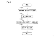
- FIG. 5 is a flowchart showing an integrated data generation processing flow executed by the data processing apparatus according to the first embodiment.
- FIG. 6 is an explanatory diagram showing an example of a priority table used for determining the priority according to the traveling state.
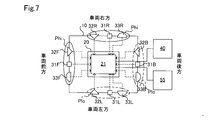
- FIG. 7 is an explanatory diagram showing the concept of priority assigned to each detector according to the position of the detector.
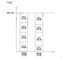
- FIG. 8 is an explanatory diagram showing an example of communication band allocation in integrated data according to the priority determined by the position of the detector.
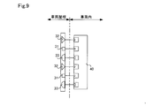
- FIG. 9 is an explanatory diagram showing a connection mode of the measuring device unit according to the conventional example to the driving support control device.
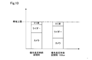
- FIG. 10 is an explanatory diagram showing an example of communication band allocation in integrated data according to the priority determined by the surrounding environment of the vehicle.
- FIG. 11 is an explanatory diagram showing an example of a priority table used for determining the priority according to the brightness environment.
- FIG. 12 is an explanatory diagram showing an example of communication band allocation in integrated data according to the priority determined by the surrounding environment of the vehicle.
- FIG. 13 is an explanatory diagram showing an example of a priority table used for determining the priority according to the weather environment.
- FIG. 14 is an explanatory diagram showing an example of a priority table used for determining the priority according to the brightness environment and the weather environment.
- FIG. 15 is a flowchart showing another generation processing flow of integrated data executed by the data processing apparatus according to the first embodiment.
- FIG. 16 is an explanatory diagram schematically showing a connection example of the data processing device and the detector according to the second embodiment.
- the in-vehicle measuring device unit and the integrated data generation method in the measuring device unit according to the present disclosure will be described below based on some embodiments.
- the vehicle-mounted measuring device unit 10 As shown in FIG. 1, the vehicle-mounted measuring device unit 10 according to the first embodiment is mounted on the vehicle 50 and used.
- the measuring device unit 10 may include at least a plurality of detection devices 31, 32, 33 arranged around the data processing device 21 and the main body 20, for example, front, back, left, right, and above. , It is desirable that it is contained in the main body 20.
- the main body 20 may be partially or wholly formed of a resin, for example, a non-metal material such as reinforced resin or carbon fiber, or may be partially or wholly formed of a metal material such as aluminum or stainless steel. ..
- the main body 20 may be further formed by using both a metal material and a non-metal material.
- the measuring device unit 10 further includes a frame (not shown) and a fixing mechanism 12 for fixing the measuring device unit 10 to the vehicle 50.
- the fixing mechanism 12 may be, for example, a mounting mechanism for mounting on the roof rail provided on the roof of the vehicle 50, or a mounting mechanism mounted between the roof of the vehicle 50 and the upper part of the door. There may be.
- the data processing device 21 is provided inside the main body 20 having a waterproof structure.
- the detectors 31, 32, 33 and the main body 20 can be easily mounted on the vehicle regardless of the shape of the vehicle 50.
- a vehicle control device 40 is arranged inside the vehicle 50, and the vehicle control device 40 uses, for example, information about an object around the vehicle 50 input from the measuring device unit 10 to assist braking and steering.
- a driving support control device 40 for executing driving support such as support and driving support is provided.
- the measuring device unit 10, specifically, the data processing device 21 and the operation support control device 40 are connected by a single wiring CV.
- the number of wiring CVs may be sufficiently smaller than the number of detectors 31, 32, 33, and is preferably 1/10 or less of the total number of detectors 31, 32, 33, for example, one wire. Is even more desirable.
- the measuring device unit 10 includes a data processing device 21 and a plurality of detectors 31, 32, 33 in the main body 20.
- the main body 20 covers the entire data processing device 21, and covers at least a part of the plurality of detectors 31, 32, 33.
- the data processing device 21 includes an integrated data generation unit 200, a plurality of detector input units 203, and one output unit 204.
- the plurality of detector input units 203 of the data processing device 21 are connected to the plurality of detectors 31, 32, 33, respectively.
- Each detector input unit 203 and each detector 31, 32, 33 are connected via wiring, and each detector input unit 203 has a shape of a connection terminal of wiring provided by each detector 31, 32, 33. It is provided with a plurality of connection portions C1, C2, and C3 having a shape corresponding to the above.
- Each detector input unit 203 is connected to the integrated data generation unit 200 via internal wiring.
- the detector input unit 203 is realized by an integrated circuit such as FPGA or ASIC, and executes a protocol conversion that converts the communication protocol adopted by each of the detectors 31, 32, 33 into the communication protocol adopted by the integrated data generation unit 200. ..
- Ethernet registered trademark
- FPD-LINK FlatPanel DisplayLink
- GVIF GigabitVideoInterface
- GMSL Gigabit Multimedia Serial Link
- LVDS low voltage differential signaling
- FIG. 2 a plurality of input units 203, each of which has connection portions C1, C2, and C3, are shown, but a plurality of connection portions C1, C2, and C3 are provided and integrated via one internal wiring.
- a single detector input unit 203 connected to the data generation unit 200 may be used.
- the detector input unit 203 sends the detection information detected by each of the detectors 31, 32, 33 to the integrated data generation unit 200 by the multiplexing communication including the frequency division multiplexing method and the time division multiplexing method. Send.
- the plurality of detectors 31, 32, 33 include a plurality of different types of detectors.
- the detector 31 is a camera
- the detector 32 is a lidar
- the detector 33 is a radar 33. It is provided with a plurality of each.
- an ultrasonic sensor another sensor using electromagnetic waves or light can be used as the detector.
- the camera 31 is an image pickup device including an image pickup element such as a CCD or an image pickup element array, and is a sensor that outputs external shape information or shape information of an object as image data as a detection result by receiving visible light.
- the lidar 32 is a sensor that detects the distance, relative velocity, and angle of the target with respect to the vehicle 50 by emitting infrared laser light and receiving the reflected light reflected by the target.
- the radar 33 is a sensor that detects the distance, relative velocity, and angle of the target with respect to the vehicle 50 by emitting millimeter waves and receiving the reflected wave reflected by the target.
- Each of the detectors 31, 32, 33 may process the light receiving intensity and the receiving intensity obtained by the detection and output the detection data consisting of the detection point sequence and the image to the integrated data generation unit 200, or Raw data such as the light reception intensity and the reception intensity obtained by the detection may be output to the integrated data generation unit 200 as they are. In the latter case, the integrated data generation unit 200 executes various processes such as image correction, lossless or lossy compression of the image, and demosaic. Further, the detection data output from each of the detectors 31, 32, 33 may be given a time stamp.
- the output unit 204 of the data processing device 21 is connected to the driving support control device 40 arranged in the vehicle 50 via the wiring CV.
- the output unit 204 is realized by an integrated circuit such as FPGA or ASIC, and executes a protocol conversion process for converting the integrated data generated in the data processing device 21 into the communication protocol adopted in the driving support control device 40. Then, it is transmitted to the driving support control device 40.
- the number of wires input to the data processing device 21 is the number of wires corresponding to the number of detectors 31, 32, 33, whereas the number of wires output from the data processing device 21 is one. The number of wires between the data processing device 21 and the operation support control device 40 is reduced.
- communication protocols such as Ethernet (10G or more), LVDS (FPD-LINK, GVIF, GMSL), and HDBASE-T are used.
- Ethernet 10G or more
- LVDS FPD-LINK, GVIF, GMSL
- HDBASE-T high-power digital signalling
- the hardware aspect of the connection terminal shape of the wiring of the detectors 31, 32, 33 and the communication of the detectors 31, 32, 33 Since it is possible to absorb and deal with differences in software such as protocols, it is possible to provide a virtual common input unit for the driving support control device 40.
- each of the detectors 31, 32, 33 is arranged around the main body 20, that is, the data processing device 21.
- the front detectors 31F, 32F, 33F in front of the vehicle
- the rear detectors 31B, 32B, 33B in the rear of the vehicle
- the right detectors 31R, 32R, 33R in the right side of the vehicle
- the left side in the vehicle left Detectors 31L, 32L, and 33L are arranged. Twelve wires are connected to the data processing device 21 from twelve detectors.
- one wire from the driving support control device 40 and one wire from the vehicle CAN 55 are connected to the data processing device 21.
- the vehicle CAN 55 is a protocol for communicating a detection signal and a control signal between each device in the vehicle 50, and is schematically shown as an information source of information obtained through the vehicle CAN 55 in the present embodiment.
- the information obtained through the vehicle CAN55 is, for example, travel information such as vehicle speed, yaw rate, steering angle, and operation of turn signals, and environmental information of the vehicle such as environmental brightness, weather, and GNSS (Global Satellite Navigation System).
- FIG. 3 shows an example in which three different types of detectors 31, 32, and 33 are arranged for the sake of facilitating the following description, but one type, two types, and even four or more types are shown. A detector may be used.
- the environmental information of the vehicle includes the data acquired by each detector and the situation around the vehicle obtained based on the data.
- the data processing device 21 includes an integrated data generation unit 200, a memory 201, a priority determination unit 202, a detector input unit 203, an output unit 204, and an information input unit 205.
- the data processing device 21 is realized in hardware by a pre-programmed integrated circuit such as FPGA or ASIC.
- the integrated data generation unit 200 executes an integrated data generation process for generating integrated data to be transmitted to the vehicle control device 40 using the detection data acquired from the detectors 31, 32, and 33.
- the priority determination unit 201 generates integrated data, among the detection data from the detectors 31, 32, 33, the detection data to be prioritized, that is, the detection data to be prioritized temporally or quantitatively. To determine.
- the memory 202 stores the detector arrangement information DI, which is information on the arrangement position of the detector, non-volatilely and read-only, and transmits the detection from the detectors 31, 32, 33 to the vehicle control device 40.
- the priority determination table for determining the priority of data may be stored readable and writable.
- a plurality of and a plurality of types of detectors 31, 32, 33 are connected to the detector input unit 203 via a detection signal line as wiring. Detection data is input from the detectors 31, 32, 33.
- a driving support control device 40 is connected to the output unit 204 via an integrated data signal line as wiring. Integrated data is output to the driving support control device 40.
- a vehicle CAN 55 is connected to the information input unit 205 via wiring. Travel information and vehicle environment information are input from the vehicle CAN55.
- the driving support control device 40 controls the output of the internal combustion engine or the motor in response to the accelerator pedal operation by the driver or regardless of the accelerator pedal operation by the driver via a driving support device (not shown), and the driver controls the output of the internal combustion engine or the motor.
- Braking by the braking device is realized independently of the pedal operation by the driver, or steering by the steering device is realized regardless of the operation of the steering wheel by the driver.
- the integrated data generation process executed by the data processing device 21 according to the first embodiment will be described.
- the processing routine shown in FIG. 4 is, for example, at predetermined time intervals, for example, several milliseconds intervals, from the start to the stop of the vehicle control system, or from the start switch is turned on until the start switch is turned off. It is executed repeatedly at.
- the integrated data generation unit 200 acquires detection data from the detectors 31, 32, and 33 via the detector input unit 203 (step S100).
- the priority determination unit 201 acquires various information such as traveling information and vehicle environment information from the vehicle CAN 55 via the information input unit 205, and the detector arrangement information DI stored in the memory 202, and uses the various information.
- the priority is determined (step S102). For the determination of the priority, for example, the priority determination table provided in the priority determination unit 201 or stored in the memory 202 based on the arrangement position of the detector and the traveling state of the vehicle 50 shown in FIG. 6 is used. Will be decided.
- the priority determination table may be dynamically updated according to the traveling state of the vehicle 50.
- the priority is determined according to the placement position of the detectors. Therefore, the detectors at each placement position are a group of detectors, for example, the front detectors 31F, 32F, and 33F are a group of front sensors. It is treated as a group and the type of each detector is not considered.
- the data processing device 21 and the operation support control device 40 are connected by a single wire, and the communication band, that is, the upper limit of the amount of transmitted data is limited.
- a priority determination table is used to determine the upper limit of the communication band, that is, the ratio of the detected data from the detectors 31, 32, 33 to be allocated to the maximum value of the transmitted data amount, in other words, the priority. Used.
- the communication band means, for example, the amount of data that can be transmitted per unit time, similar to terms such as transmission rate and transfer speed, and generally involves overwriting of a buffer or discarding data on the receiving side. It is determined by the amount of data that can be processed per unit time without any problem.
- the proportions are increased to 30% and 40%, respectively, and the priorities of the left detectors 31L, 32L, 33L and the rear detectors 31B, 32B, 33B surrounded by the alternate long and short dash line Plo are 10% and 20%, respectively. It is lowered to. If no priority is assigned, the same 25% ratio is assigned to the detectors at each placement position.
- the specific priority shown in FIG. 6, that is, the allocation ratio is only an example, and may be appropriately determined as long as the tendency of allocation according to the running state of the vehicle 50 is maintained. In addition, the ratio may be adjusted using a result such as machine learning.
- an actual driving scene for example, there are a turn crossing an oncoming lane, a right turn scene in left-hand traffic, a right turn signal or a left turn signal in a left turn scene in right-hand traffic, and an intersection without a signal, which is more complicated than the above example. Therefore, it may be further subdivided according to the current traveling state and the surrounding environment including an object such as another vehicle by learning.
- the driver may estimate and determine the insufficient monitoring ability, determine the coefficient and weighting for the ratio, and reflect it in the final ratio.
- the priority of the front detectors 31F, 32F, and 33F is increased, but since there is a possibility that the object may approach from the rear to the side, the priority of the detectors at other arrangement positions is considered. Are the same.
- the front detectors 31F, 32F, 33F, and the left detectors 31L, 32L, 33L are given higher priority, and when the vehicle 50 is moving backward, the probability of approaching an object from the front is low, so that the vehicle is rearward.
- the priorities of the detectors 31B, 32B, 33B, the right detectors 31R, 32R, 33R, and the left detectors 31L, 32L, 33L have been increased, and the priorities of the front detectors 31F, 32F, 33F have been greatly reduced.
- the priority of the left detectors 31L, 32L, 33L and the rear detectors 31B, 32B, 33B is increased, and the priority of the right detectors 31R, 32R, 33R is increased. It is greatly reduced.
- the priority of the right detectors 31R, 32R, 33R and the rear detectors 31B, 32B, 33B is increased, and the priority of the left detectors 31L, 32L, 33L is increased. It is greatly reduced.
- the priority is determined according to the arrangement position of the detector group and the running state of the vehicle, so that at least a plurality of detectors of one type may be arranged at different arrangement positions. , A technical effect is exhibited when at least one of the detectors 31, 32, and 33 is used.
- the integrated data generation unit 200 generates integrated data according to the determined priority (step S104).
- the generation of integrated data according to the priority means the determination of the amount of data for transmission according to the priority, that is, the allocation of the total amount of data to be transmitted, and when the time division multiplexing method is adopted.
- the amount of data transmitted from the detector with high priority is increased, and the number of transmissions becomes priority.
- integrated data may be generated as a data frame for transmission in which the detected data from the detectors 31, 32, and 33 are combined in a data amount according to the priority.
- the ratio of the detection data from the front detectors 31F, 32F, 33F and the detection data from the right detectors 31R, 32R, 33R is large.
- Integrated data is generated.
- FIG. 8 shows the ratio of the detected data from the detector at each arrangement position in the integrated data generated before the priority is reflected, that is, when the priority is not reflected for comparison.
- the reduction of the ratio in the integrated data is realized by reducing the capacity of the detection data output from each of the detectors 31, 32, 33, for example, the capacity reduction by thinning out the data such as reduction of the number of detection points and reduction of the resolution. , Realized by reducing the frequency of transmission of detected data.
- the integrated data generation unit 200 transmits integrated data to the driving support control device 40 via the output unit 204 (step S106), and the processing routine ends.
- the integrated data generation unit 200 generates the integrated data, in addition to allocating the amount of data for transmission, when a common data format is used between the data processing device 21 and the vehicle control device 40, the common data format It may include integrated processing such as format conversion to and frame rate integration.
- the data processing device 21 includes a plurality of input units 203 connected to the plurality of detectors 31, 32, 33, respectively, and is integrated.
- the data generation unit 200 generates integrated data using the detection data from the plurality of detectors 31, 32, 33 input via the plurality of input units 203, and drives the vehicle 50 via the output unit 204. It can be transmitted to the support control device 40. Therefore, as shown in FIG. 9, a large number of detectors are integrated into the measuring device unit as compared with the conventional measuring device unit in which the detectors 31, 32, and 33 are directly wired to the driving support control device 40.
- the number of wirings between each detector and the driving support control device provided in the vehicle can be reduced, and the wiring design can be facilitated. Further, since the number of wirings from the outside of the vehicle 50 to the inside of the vehicle 50 is reduced, the number of waterproof points at the boundary between the outside and the inside of the vehicle 50 can be reduced, and the waterproof measures can be facilitated.
- the detectors 31, 32, 33 assigned to the integrated data are assigned according to the traveling state of the vehicle 50 and the arrangement positions of the detectors 31, 32, 33.
- the priority of the data amount, that is, the allocation amount is determined. Therefore, it is possible to preferentially transmit the detection data of the detector related to the driving support that is likely to be executed by the driving support control device 40 in the moving vehicle 50. As a result, it is possible to prevent or suppress data loss and transmission delay required due to the excess of the communication band due to transmission without considering the priority, and the accuracy and timeliness of the operation support control by the operation support control device 40. Is improved.
- FIG. 10 shows an example of the ratio of the detected data in the integrated data generated when the priority is determined according to the ambient brightness environment of the vehicle 50 obtained by the illuminance sensor as the ambient environment. More specifically, it shows the priority assignment when a plurality of three types of detectors, a camera 31, a rider 32, and a radar 33, are provided.
- the priority before the priority is reflected, for example, it is during the daytime, and after the priority is reflected, it is, for example, at night.
- the nighttime means an ambient light state in which the illuminance obtained by the illuminance sensor shows a predetermined illuminance, for example, a value lower than 100 lux.
- a light receiving type (passive type) detector 31 that is, a light emitting light receiving type (active type) detector 32 that is not easily affected by ambient light because the resolution of the camera is low. That is, the detector 33 that is not affected by the rider or ambient light, that is, the millimeter wave radar is given higher priority.
- the amount of detected data of the detector 32 in the integrated data is slightly increased and the amount of detected data of the detector 31 is slightly reduced in the evening as compared with the daytime.
- the amount of detected data of the detector 32 in the integrated data is increased, the amount of detected data of the detector 33 is slightly increased, and the amount of detected data of the detector 31 is reduced as compared with the time of daytime or evening.
- the accuracy and timeliness of the driving support control in the driving support control device 40 can be improved.
- the arrangement positions of the detectors 31, 32, and 33 are not reflected in the priority. Further, in FIG.
- an illuminance of 1000 lux corresponds to an ambient light of about sunset
- 100 lux corresponds to an ambient light of about when a night street light is lit
- 1 lux corresponds to an ambient light of about no night street light.
- an intermediate value of the ratio shown in FIG. 11 may be used according to the output illuminance value of the illuminance sensor.
- FIG. 12 shows an example of the ratio of the detected data in the integrated data generated when the priority is determined according to the weather environment around the vehicle 50 obtained by the rain sensor as the surrounding environment.
- the priority before the priority is reflected, it is, for example, in fine weather, and after the priority is reflected, it is, for example, in rainy weather, fog generation, and snowy weather.
- the rainy weather and the snowy weather mean the weather conditions in which raindrops and snow are detected by the rain sensor. Since the configuration and principle of the rain sensor are known, the description thereof will be omitted.
- the resolution of the optical detectors 31 and 32 is the radio wave detector 33, that is, which is not easily affected by attenuation by raindrops, snowflakes, and water vapor. Since it is lower than the radar, raise the priority of the radar.
- An example of the priority that is, the ratio of the amount of data from each of the detectors 31, 32, 33 to the integrated data is shown in FIG.
- the amount of detection data of the detector 33 in the integrated data is increased as compared with the case of fine weather, and the detectors 31 and 32 are detected.
- the amount of data is reduced.
- the ratio of the amount of data from the detector 33 is increased to four times that in fine weather.
- the same ratio as in rainy weather with rainfall of 15 mm / h or more is applied, and in the case of snowy weather, rainfall is 1 mm / h or more and less than 15 mm / h in rainy weather.
- the same ratio as in the case of rainy weather with a rainfall of 15 mm / h or more may be applied according to the amount of snowfall.
- an intermediate value of the ratio shown in FIG. 13 may be used according to the output value of the rain sensor or the like.
- the arrangement positions of the detectors 31, 32, and 33 are not reflected in the priority.
- the weather conditions such as fog and snow may be acquired by using, for example, regional weather information provided through various road-to-vehicle communication and vehicle-to-vehicle communication.
- FIG. 14 even if the brightness environment and the weather environment are considered in a complex manner and the priority, that is, the ratio of the amount of data from the detectors 31, 32, and 33 to the integrated data is set. good.
- a plurality of environments as environmental information around the vehicle 50, it is possible to further improve the accuracy and timeliness of the driving support control in the driving support control device 40.
- the priority may be further determined in consideration of the arrangement positions of the detectors 31, 32, and 33.
- Environmental information such as environmental brightness and weather is taken into consideration along with the traveling information of the vehicle 50, and the priority, that is, the ratio of the detected data from each detector to the integrated data is used by using the position of the detector and the type of the detector. May be determined.
- integrated data including the detection data from each detector can be generated at a ratio according to the traveling information of the vehicle 50 and the environmental information of the vehicle, the accuracy of the driving support control in the driving support control device 40 , The timeliness can be further improved.
- the priority of the detection data from the detectors 31, 32, 33 may be determined according to the dynamic request from the driving support control device 40 for the running of the vehicle 50.
- the driving support is executed by the driving support control device 40.
- the accuracy and timeliness can be further improved, the transmission of unnecessary detection data can be suppressed, and the communication band in the integrated data can be provided with a margin.
- 15 is, for example, at predetermined time intervals, for example, several milliseconds intervals, from the start to the stop of the vehicle control system, or from the start switch is turned on until the start switch is turned off. It is executed repeatedly at. The processing steps described with reference to FIG. 5 will be briefly described.
- the integrated data generation unit 200 acquires detection data from each of the detectors 31, 32, 33 via the detector input unit 203 (step S200).
- the priority determination unit 201 determines a reference table corresponding to environmental information around the vehicle 50 (step S202).
- the reference table is, for example, the reference table shown in FIGS. 11, 13 and 14, and is at least one of a brightness environment and a weather environment depending on the sensor type for acquiring the environment information of the vehicle included in the vehicle 50.
- the reference table corresponding to can be determined.
- the reference table shown in FIGS. 11, 13 and 14 may be provided by, for example, the priority determination unit 201, or may be stored in the memory 202.
- the priority determination unit 201 determines the surrounding environment priority using the vehicle environment information acquired from the vehicle CAN 55 via the information input unit 205 and the determined reference table (step S204).
- the surrounding environment priority is determined by the determination procedure described with reference to FIGS. 10 to 13 with the illuminance and the weather condition as parameters.
- the priority determination unit 201 uses various information such as travel information and vehicle environment information acquired from the vehicle CAN 55 via the information input unit 205, and the detector arrangement information DI stored in the memory 202 to prioritize the traveling state. Is determined (step S206).
- the integrated data generation unit 200 generates integrated data according to the determined surrounding environment priority and driving state priority (step S208). More specifically, each ratio to each detector 31, 32, 33 in the determined surrounding environment priority is multiplied by each ratio to each detector 31, 32, 33 in the determined driving state priority. Can be determined by doing. For example, as shown in FIG. 6, when turning right, the amount of data from the right detectors 31R, 32R, and 33R occupies a 40% band, and as shown in FIG. 14, the environment around the vehicle is sunny-daytime. In some cases, the amount of data in the camera 31 occupies 60% of the band, so 24% of the band is allocated to the camera 31R as the right detector.
- the integrated data generation unit 200 transmits integrated data to the driving support control device 40 via the output unit 204 (step S210), and the processing routine ends.
- a case where one camera 31R, one rider 32R, and one radar 33R are arranged as the right detector is described as an example.
- the measuring device unit 10 according to the first embodiment includes one data processing device 21, but the measuring device unit 10 according to the second embodiment is inside two main bodies 20a and 20b as shown in FIG.
- the data processing devices 21a and 21b included in the data processing device 21a and 21b are provided. Since the configurations and functions of the devices and devices including the data processing devices 21a and 21b have already been described in the first embodiment, the same symbols used in the first embodiment are added. The explanation will be omitted.
- a plurality of detectors 31, 32, and 33 arranged in the same direction of the vehicle 50 are connected to different data processing devices 21a and 21b, respectively. Further, different types of detectors are connected to different data processing devices 21a and 21b. Therefore, even if one of the data processing devices 21a and 21b fails or malfunctions, redundancy is ensured. Therefore, integrated data including a plurality of types of detection data is provided for the driving support control device 40. Can be continuously transmitted, and the vehicle 50 can continue running under driving support control including autonomous driving, or shift to evasive running.
- the data processing devices 21a and 21b and the operation support control device 40 are connected to each other, it is possible to secure twice the communication band, and the detectors 31, 32 and 33 shown in the integrated data can be used. It is possible to allocate a larger amount of detected data to the integrated data, and it is possible to suppress the reduction rate of the detected data having a low priority.
- the amount of detection data output by the camera 31 is larger than that of the rider 32 and the radar 33, but by distributing the number of connections of the camera 31 to one data processing device 21a and 21b, a margin is provided in the communication band of the integrated data. It is possible to suppress the reduction of the data amount of the detection data having a low priority. Further, it is possible to increase the number of detectors 31, 32, 33 to be arranged while guaranteeing the minimum data amount of each detection data.
- different types of detectors are connected to different data processing devices 21a and 21b to provide redundancy regarding the types of detectors, but the same type of detectors are the same data processing device 21a, By connecting to 21b, the redundancy regarding the arrangement position of the detector may be improved. Further, by providing a plurality of detectors of the same type in each direction of the vehicle 50 and connecting each detector of the same type to different data processing devices 21a and 21b, the redundancy regarding the arrangement position of the detectors is further improved. Is also good.
- the vehicle control device 40 is the driving support control device 40.
- the present invention is not limited to this, and various control devices such as a vehicle control device and a communication gateway control device in an in-vehicle network may be used. In either case, there is an advantage that the number of wirings from the outside of the vehicle 50 to the inside of the vehicle 50 can be reduced.
- the integrated data generation process is realized by a pre-programmed integrated circuit such as FPGA or ASIC.
- the CPU executes the integrated data generation program
- the integrated data is software-wise.
- the generation process may be realized, or it may be realized in hardware by a discrete circuit. That is, the control unit and its method in each of the above embodiments are provided by a dedicated computer provided by configuring a processor and memory programmed to perform one or more functions embodied by a computer program. It may be realized.
- the controls and methods thereof described in the present disclosure may be implemented by a dedicated computer provided by configuring the processor with one or more dedicated hardware logic circuits.
- the controls and methods thereof described in the present disclosure consist of a combination of a processor and memory programmed to perform one or more functions and a processor composed of one or more hardware logic circuits. It may be realized by one or more dedicated computers. Further, the computer program may be stored in a computer-readable non-transitional tangible recording medium as an instruction executed by the computer.
Landscapes
- Engineering & Computer Science (AREA)
- Physics & Mathematics (AREA)
- General Physics & Mathematics (AREA)
- Radar, Positioning & Navigation (AREA)
- Remote Sensing (AREA)
- Mechanical Engineering (AREA)
- Computer Networks & Wireless Communication (AREA)
- Transportation (AREA)
- Human Computer Interaction (AREA)
- Automation & Control Theory (AREA)
- Geophysics (AREA)
- General Life Sciences & Earth Sciences (AREA)
- Life Sciences & Earth Sciences (AREA)
- Electromagnetism (AREA)
- Traffic Control Systems (AREA)
- Radar Systems Or Details Thereof (AREA)
- Optical Radar Systems And Details Thereof (AREA)
- Arrangements For Transmission Of Measured Signals (AREA)
- Geophysics And Detection Of Objects (AREA)
- Fittings On The Vehicle Exterior For Carrying Loads, And Devices For Holding Or Mounting Articles (AREA)
Priority Applications (2)
| Application Number | Priority Date | Filing Date | Title |
|---|---|---|---|
| CN202080080033.5A CN114730519A (zh) | 2019-11-18 | 2020-10-27 | 车载用的测量装置单元以及车载用的测量装置单元中的综合数据生成方法 |
| US17/663,474 US12187295B2 (en) | 2019-11-18 | 2022-05-16 | Vehicle measuring device unit and method of generating integrated data in vehicle measuring device unit |
Applications Claiming Priority (2)
| Application Number | Priority Date | Filing Date | Title |
|---|---|---|---|
| JP2019207578A JP2021081886A (ja) | 2019-11-18 | 2019-11-18 | 車載用の計測装置ユニットおよび車載用の計測装置ユニットにおける統合データ生成方法 |
| JP2019-207578 | 2019-11-18 |
Related Child Applications (1)
| Application Number | Title | Priority Date | Filing Date |
|---|---|---|---|
| US17/663,474 Continuation US12187295B2 (en) | 2019-11-18 | 2022-05-16 | Vehicle measuring device unit and method of generating integrated data in vehicle measuring device unit |
Publications (1)
| Publication Number | Publication Date |
|---|---|
| WO2021100418A1 true WO2021100418A1 (ja) | 2021-05-27 |
Family
ID=75965174
Family Applications (1)
| Application Number | Title | Priority Date | Filing Date |
|---|---|---|---|
| PCT/JP2020/040239 Ceased WO2021100418A1 (ja) | 2019-11-18 | 2020-10-27 | 車載用の計測装置ユニットおよび車載用の計測装置ユニットにおける統合データ生成方法 |
Country Status (4)
| Country | Link |
|---|---|
| US (1) | US12187295B2 (https=) |
| JP (1) | JP2021081886A (https=) |
| CN (1) | CN114730519A (https=) |
| WO (1) | WO2021100418A1 (https=) |
Families Citing this family (5)
| Publication number | Priority date | Publication date | Assignee | Title |
|---|---|---|---|---|
| JP7382791B2 (ja) * | 2019-10-30 | 2023-11-17 | 株式会社日立製作所 | 異常判定装置、車両支援システム |
| CN117980209A (zh) * | 2021-11-09 | 2024-05-03 | 日立安斯泰莫株式会社 | 电子控制装置及车辆控制系统 |
| JP7571717B2 (ja) * | 2021-12-10 | 2024-10-23 | トヨタ自動車株式会社 | 情報処理装置および情報処理方法 |
| JP7718304B2 (ja) * | 2022-03-24 | 2025-08-05 | トヨタ自動車株式会社 | 映像伝送システム、車両、および映像伝送方法 |
| JP2025103267A (ja) * | 2023-12-27 | 2025-07-09 | 川崎車両株式会社 | 機械学習装置、除草作業の要否判定システムおよび除草作業の要否判定方法 |
Citations (5)
| Publication number | Priority date | Publication date | Assignee | Title |
|---|---|---|---|---|
| US20180113209A1 (en) * | 2016-10-21 | 2018-04-26 | Waymo Llc | Radar generated occupancy grid for autonomous vehicle perception and planning |
| WO2018175808A1 (en) * | 2017-03-23 | 2018-09-27 | Uber Technologies, Inc. | Dynamic sensor selection for self-driving vehicles |
| JP2019012079A (ja) * | 2014-08-28 | 2019-01-24 | ウェイモ エルエルシー | 車両レーダ調整及び干渉低減のための方法及びシステム |
| US20190049958A1 (en) * | 2017-08-08 | 2019-02-14 | Nio Usa, Inc. | Method and system for multiple sensor correlation diagnostic and sensor fusion/dnn monitor for autonomous driving application |
| WO2019043855A1 (ja) * | 2017-08-31 | 2019-03-07 | 三菱電機株式会社 | データ伝送装置、データ処理システムおよびデータ伝送方法 |
Family Cites Families (15)
| Publication number | Priority date | Publication date | Assignee | Title |
|---|---|---|---|---|
| JPH04260834A (ja) * | 1991-02-14 | 1992-09-16 | Nissan Motor Co Ltd | 車両システムの故障判定装置 |
| JP2006024103A (ja) * | 2004-07-09 | 2006-01-26 | Honda Motor Co Ltd | 車両の走行支援装置 |
| US7986246B2 (en) * | 2006-03-31 | 2011-07-26 | Itron, Inc. | Integrated data collection, anomaly detection and investigation, such as integrated mobile utility meter reading, theft detection and investigation system |
| JP2008205594A (ja) * | 2007-02-16 | 2008-09-04 | Auto Network Gijutsu Kenkyusho:Kk | 車載映像通信システム |
| JP2008207627A (ja) * | 2007-02-23 | 2008-09-11 | Auto Network Gijutsu Kenkyusho:Kk | 車載撮像システム、撮像装置及び表示制御装置 |
| US8126642B2 (en) * | 2008-10-24 | 2012-02-28 | Gray & Company, Inc. | Control and systems for autonomously driven vehicles |
| JP2012245812A (ja) * | 2011-05-25 | 2012-12-13 | Denso Corp | 車両用通信装置 |
| JP5983515B2 (ja) * | 2013-04-18 | 2016-08-31 | 株式会社デンソー | 制御システム |
| US9563199B1 (en) * | 2013-11-27 | 2017-02-07 | Google Inc. | Assisted perception for autonomous vehicles |
| JP2017058385A (ja) * | 2015-09-14 | 2017-03-23 | 新明工業株式会社 | 運転状況確認システム、車両状態通信装置および車両通信プログラム |
| US11283877B2 (en) * | 2015-11-04 | 2022-03-22 | Zoox, Inc. | Software application and logic to modify configuration of an autonomous vehicle |
| US10343620B2 (en) | 2016-04-22 | 2019-07-09 | Uber Technologies, Inc. | External sensor assembly for vehicles |
| JP2019122005A (ja) * | 2018-01-11 | 2019-07-22 | アンリツ株式会社 | ビット誤り率測定装置及びビット誤り率測定方法 |
| US10175340B1 (en) * | 2018-04-27 | 2019-01-08 | Lyft, Inc. | Switching between object detection and data transfer with a vehicle radar |
| US11037000B2 (en) * | 2019-09-27 | 2021-06-15 | Gm Cruise Holdings Llc | Intent-based dynamic change of resolution and region of interest of vehicle perception system |
-
2019
- 2019-11-18 JP JP2019207578A patent/JP2021081886A/ja active Pending
-
2020
- 2020-10-27 WO PCT/JP2020/040239 patent/WO2021100418A1/ja not_active Ceased
- 2020-10-27 CN CN202080080033.5A patent/CN114730519A/zh active Pending
-
2022
- 2022-05-16 US US17/663,474 patent/US12187295B2/en active Active
Patent Citations (5)
| Publication number | Priority date | Publication date | Assignee | Title |
|---|---|---|---|---|
| JP2019012079A (ja) * | 2014-08-28 | 2019-01-24 | ウェイモ エルエルシー | 車両レーダ調整及び干渉低減のための方法及びシステム |
| US20180113209A1 (en) * | 2016-10-21 | 2018-04-26 | Waymo Llc | Radar generated occupancy grid for autonomous vehicle perception and planning |
| WO2018175808A1 (en) * | 2017-03-23 | 2018-09-27 | Uber Technologies, Inc. | Dynamic sensor selection for self-driving vehicles |
| US20190049958A1 (en) * | 2017-08-08 | 2019-02-14 | Nio Usa, Inc. | Method and system for multiple sensor correlation diagnostic and sensor fusion/dnn monitor for autonomous driving application |
| WO2019043855A1 (ja) * | 2017-08-31 | 2019-03-07 | 三菱電機株式会社 | データ伝送装置、データ処理システムおよびデータ伝送方法 |
Also Published As
| Publication number | Publication date |
|---|---|
| JP2021081886A (ja) | 2021-05-27 |
| US20220274606A1 (en) | 2022-09-01 |
| CN114730519A (zh) | 2022-07-08 |
| US12187295B2 (en) | 2025-01-07 |
Similar Documents
| Publication | Publication Date | Title |
|---|---|---|
| WO2021100418A1 (ja) | 車載用の計測装置ユニットおよび車載用の計測装置ユニットにおける統合データ生成方法 | |
| US20230147535A1 (en) | Vehicle position estimation device and traveling control device | |
| US10479269B2 (en) | Lighting apparatus for vehicle and vehicle having the same | |
| JP7310524B2 (ja) | 遠隔自動運転車両、及び車両遠隔指示システム | |
| US20210403015A1 (en) | Vehicle lighting system, vehicle system, and vehicle | |
| US20210024084A1 (en) | Path providing device and path providing method thereof | |
| US11507789B2 (en) | Electronic device for vehicle and method of operating electronic device for vehicle | |
| US20200126325A1 (en) | Electronic control unit and communication device | |
| US11397248B2 (en) | Sensing system and driving support system | |
| JP7187291B2 (ja) | 赤外線カメラシステム及び車両 | |
| US11814081B2 (en) | Control system, control method, vehicle, and computer-readable storage medium | |
| US20250175713A1 (en) | Brightness based chromaticity weighting for improved illuminant color estimation for auto white balancing | |
| JP7727466B2 (ja) | 車両走行の遠隔制御システム | |
| US12574652B2 (en) | Fallback mechanism for auto white balancing | |
| JP2020069969A (ja) | 車両制御システム | |
| US20230251649A1 (en) | Remote operation system, remote operation control method, and remote operator terminal | |
| KR102838986B1 (ko) | 차량, 차량 제어 방법 및 차량의 운전자 보조 시스템 | |
| WO2022153896A1 (ja) | 撮像装置、画像処理方法及び画像処理プログラム | |
| JP2025092496A (ja) | 車両のナンバープレートの文字列を識別するための電子装置及び方法 | |
| US12444205B2 (en) | System and vehicle including the same | |
| US20230273044A1 (en) | Route provision device and route provision method thereof | |
| WO2022153888A1 (ja) | 固体撮像装置、固体撮像装置の制御方法及び固体撮像装置の制御プログラム | |
| JP7375678B2 (ja) | 車両制御方法、車両制御プログラム、及び車両制御システム | |
| US20240192360A1 (en) | Driving assistance system and driving assistance method | |
| US20240208529A1 (en) | Sensor data transfer with self adaptive configurations for autonomous driving vehicle |
Legal Events
| Date | Code | Title | Description |
|---|---|---|---|
| 121 | Ep: the epo has been informed by wipo that ep was designated in this application |
Ref document number: 20889192 Country of ref document: EP Kind code of ref document: A1 |
|
| NENP | Non-entry into the national phase |
Ref country code: DE |
|
| 122 | Ep: pct application non-entry in european phase |
Ref document number: 20889192 Country of ref document: EP Kind code of ref document: A1 |