WO2021100221A1 - 液冷ジャケットの製造方法 - Google Patents
液冷ジャケットの製造方法 Download PDFInfo
- Publication number
- WO2021100221A1 WO2021100221A1 PCT/JP2020/013823 JP2020013823W WO2021100221A1 WO 2021100221 A1 WO2021100221 A1 WO 2021100221A1 JP 2020013823 W JP2020013823 W JP 2020013823W WO 2021100221 A1 WO2021100221 A1 WO 2021100221A1
- Authority
- WO
- WIPO (PCT)
- Prior art keywords
- sealing body
- jacket
- stirring pin
- sealing
- joining step
- Prior art date
- Legal status (The legal status is an assumption and is not a legal conclusion. Google has not performed a legal analysis and makes no representation as to the accuracy of the status listed.)
- Ceased
Links
Images


Classifications
-
- B—PERFORMING OPERATIONS; TRANSPORTING
- B23—MACHINE TOOLS; METAL-WORKING NOT OTHERWISE PROVIDED FOR
- B23K—SOLDERING OR UNSOLDERING; WELDING; CLADDING OR PLATING BY SOLDERING OR WELDING; CUTTING BY APPLYING HEAT LOCALLY, e.g. FLAME CUTTING; WORKING BY LASER BEAM
- B23K20/00—Non-electric welding by applying impact or other pressure, with or without the application of heat, e.g. cladding or plating
- B23K20/12—Non-electric welding by applying impact or other pressure, with or without the application of heat, e.g. cladding or plating the heat being generated by friction; Friction welding
Definitions
- the present invention relates to a method for manufacturing a liquid-cooled jacket.
- Patent Document 1 discloses a method for manufacturing a liquid-cooled jacket in which a jacket body and a sealing body that seals an opening of the jacket body are joined by friction stir welding.
- a rotating tool is inserted vertically from the side surface of the jacket body and the sealing body, and friction stir welding is performed by rotating the jacket body around the jacket body.
- a rotation tool in order to rotate the rotation tool around the jacket body with the rotation tool and the side surface of the jacket body perpendicular to each other, a rotation tool is provided, for example, a rotation driving means such as a spindle unit at the tip. It is necessary to change / adjust the angle and insertion position of the rotation center axis of the rotation tool by attaching it to the arm robot. For this reason, there is a problem that ancillary equipment such as a device for driving the rotary tool is costly, and as a result, the manufacturing cost is high.
- the present invention comprises a jacket body having a bottom, a peripheral wall portion rising from the peripheral edge of the bottom, and a support column rising from the bottom, and a sealing body for sealing the opening of the jacket body.
- This is a method for manufacturing a liquid-cooled jacket in which the jacket body and the sealing body are joined by frictional stirring, and the outer peripheral surface of the stirring pin of the rotary tool used in frictional stirring is inclined so as to be tapered.
- the first butt portion is rubbed and agitated by making a relative circumference around the peripheral wall portion at a predetermined depth along the first butt portion in a state of being in contact with the peripheral wall portion and the sealing body.
- the holding portion is held while pressing the bottom portion of the jacket body and the surface of the sealing body from both outer sides with a pair of holding portions. It is characterized in that the jacket body and the sealing body are rotated or moved in parallel by the use to rub and stir the jacket body and the sealing body.
- the present invention includes a jacket body having a bottom portion, a peripheral wall portion rising from the peripheral edge of the bottom portion, and a support column rising from the bottom portion, and a hole into which the tip of the support column is inserted, and seals the opening of the jacket body.
- This is a method for manufacturing a liquid-cooled jacket which is composed of a sealing body and joins the jacket body and the sealing body by friction stirring, and the outer peripheral surface of a stirring pin of a rotating tool used for friction stirring is tapered.
- a column step portion having a step bottom surface and a step side surface rising from the step bottom surface is formed at the tip of the column, and the step bottom surface of the column is positioned at the same height as the end surface of the peripheral wall portion.
- the first butt portion is formed by superimposing the above columns, and the step side surface of the support column and the hole wall of the hole portion are abutted to form a step side surface butt portion.
- the first one that rubs and stirs the first butt portion by making a relative circumference around the peripheral wall portion at a predetermined depth along the first butt portion in a state of being in contact with the peripheral wall portion and the sealing body.
- the holding portion is used while pressing and holding the bottom portion of the jacket body and the surface of the sealing body from both outer sides with a pair of holding portions. The jacket body and the sealing body are rotated or moved in parallel to rub and stir the jacket body and the sealing body.
- the jacket body and the sealing body are rotated or translated while the bottom of the jacket body and the surface of the sealing body are held by the pair of holding portions, so that the jacket body and the sealing body are held during the first joining step.
- the part and the rotation tool do not interfere. That is, the jig for positioning the jacket body and the sealing body does not hinder the movement of the rotating tool.
- ancillary equipment such as a device for driving the rotary tool can be simplified, and a liquid-cooled jacket can be manufactured at low cost.
- the stirring pin of the rotating tool is inserted into the second butt portion from the surface of the sealing body, and only the stirring pin is brought into contact with the sealing body or the sealing body and the support column. It is preferable to further include a second joining step in which the second butt portion is moved relative to the second butt portion at a predetermined depth and the second butt portion is frictionally agitated.
- the stirring pin of the rotating tool is inserted into the step side surface abutting portion from the surface of the sealing body, and the step side surface abutting is performed in a state where only the stirring pin is in contact with the sealing body and the support column. It is preferable to further include a second joining step of frictionally agitating the step side surface abutting portion by relatively moving along the portion at a predetermined depth.
- the joint strength can be increased.
- the stirring pin is rotated at a predetermined rotation speed to perform frictional stirring, and when the stirring pin is pulled out in the first main joining step, the stirring pin is gradually pulled out from the predetermined rotation speed. It is preferable to move the rotation tool relative to the end position while increasing the rotation speed.
- the stirring pin is rotated at a predetermined rotation speed to perform frictional stirring, and when the stirring pin is inserted in the first main joining step, the rotation speed is higher than the predetermined rotation speed. It is preferable that the stirring pin is inserted in a state of being rotated at a speed, and the stirring pin is relatively moved to the first butt portion while gradually reducing the rotation speed.
- friction stir welding can be preferably performed.
- the liquid-cooled jacket can be manufactured at low cost.
- the liquid-cooled jacket 1 is composed of a jacket body 2 and a sealing body 3.
- the liquid-cooled jacket 1 is a device that circulates a fluid inside to cool an arranged heating element.
- the jacket body 2 and the sealing body 3 are integrated by friction stir welding.
- the "front surface” means the surface opposite to the "back surface”.
- the jacket body 2 is mainly composed of a bottom portion 10 and a peripheral wall portion 11.
- the jacket body 2 may be any metal (aluminum, aluminum alloy, magnesium, magnesium alloy, copper, copper alloy, titanium, titanium alloy, etc.) that can be agitated by friction, but in the present embodiment, it is made of an aluminum alloy.
- the bottom portion 10 is a plate-shaped member having a rectangular shape.
- the peripheral wall portion 11 is a wall portion that rises in a rectangular frame shape from the peripheral edge portion of the bottom portion 10.
- the corner of the peripheral wall portion 11 may be a right angle, but in the present embodiment, a round chamfering process is performed.
- a support column 12 stands up at the bottom 10.
- the number of columns 12 is not particularly limited, but is two in this embodiment.
- the end surface 12a of the support column 12 has the same height as the end surface 11a of the peripheral wall portion 11.
- a recess 13 is formed in the bottom portion 10 and the peripheral wall portion 11.
- the jacket body 2 of the present embodiment is integrally formed, for example, the peripheral wall portion 11 may be divided and joined by a seal member to be integrated.
- the sealing body 3 is a plate-shaped member that seals the opening of the jacket body 2.
- the corners of the sealing body 3 may be right angles, but in the present embodiment, round chamfering is performed.
- the sealing body 3 is not particularly limited as long as it is a metal capable of friction stir welding, but in the present embodiment, it is formed mainly containing an aluminum alloy.
- the preparation step is a step of preparing the jacket body 2 and the sealing body 3.
- the jacket body 2 and the sealing body 3 are not particularly limited in terms of manufacturing method, but the jacket body 2 is molded by die casting, for example.
- the sealing body 3 is formed by, for example, extrusion molding.
- the mounting step is a step of mounting the sealing body 3 on the jacket body 2. By the mounting step, the end surface 11a of the peripheral wall portion 11 and the back surface 3b of the sealing body 3 are abutted to form the first abutting portion J1.
- the first butt portion J1 is formed in a rectangular shape in a plan view along the periphery of the sealing body 3.
- the end surface 12a of the support column 12 and the back surface 3b of the sealing body 3 are abutted to form the second abutting portion J2.
- the side surface 11c of the peripheral wall portion 11 and the side surface 3c of the sealing body 3 are flush with each other.
- the jacket body 2 and the sealing body 3 may be temporarily joined by welding, friction stir welding, or the like.
- the first main joining step is a step of friction stir welding of the first butt portion J1 using the rotary tool F.
- a holding step and a friction stir welding step are performed.
- the jacket body 2 and the sealing body 3 are pressed from both outer sides by a holding device (jig) provided with a pair of holding portions 22 to hold the jacket body 2.
- a holding device jig
- an intermediate plate 21 is interposed between the holding portion 22 and the bottom portion 10 and between the holding portion 22 and the sealing body 3, respectively.
- the holding portion 22 has a columnar shape, and its end faces come into surface contact with the intermediate plates 21 and 21, respectively.
- the holding portion 22 of the holding device, the jacket body 2 and the sealing body 3 rotate or move in parallel in synchronization with each other. That is, the sandwiching device rotates the jacket body 2 and the sealing body 3 in the circumferential direction while the bottom portion 10 of the jacket body 2 and the surface 3a of the sealing body 3 are pressed and sandwiched by the holding portions 22 and 22, respectively. At the same time, it can be linearly moved up and down, left and right, and front and back.
- the rotation tool F includes a connecting portion F1 and a stirring pin F2.
- the rotary tool F is made of, for example, tool steel.
- the connecting portion F1 is a portion connected to the rotating shaft of the friction stir device (not shown).
- the connecting portion F1 has a columnar shape, and a screw hole (not shown) for fastening a bolt is formed.
- the stirring pin F2 hangs down from the connecting portion F1 and is coaxial with the connecting portion F1.
- the stirring pin F2 is tapered as it is separated from the connecting portion F1.
- a flat flat surface perpendicular to the rotation center axis C and flat is formed at the tip of the stirring pin F2.
- a spiral groove is engraved on the outer peripheral surface of the stirring pin F2.
- the spiral groove in order to rotate the rotation tool F clockwise, the spiral groove is formed counterclockwise from the base end to the tip end. In other words, the spiral groove is formed counterclockwise when viewed from above when the spiral groove is traced from the base end to the tip end.
- the spiral groove in this case is formed clockwise when viewed from above when the spiral groove is traced from the base end to the tip end.
- the rotation tool F is attached to a friction stir device that can move in the horizontal direction and the vertical direction.
- the rotation tool F may be attached to a robot arm having a rotation driving means such as a spindle unit at its tip.
- the rotary tool F attached to the friction stir welder is rotated clockwise.
- the position of the rotation tool F is fixed so as not to move relative to the friction stir device. That is, the rotating tool F is not displaced with respect to the friction stir welding device, but the jacket body 2 and the sealing body 3 side are moved with respect to the rotating tool F to perform friction stir welding.
- a holding step of holding the jacket body 2 and the sealing body 3 is performed, and the jacket body 2 and the sealing body 3 are held by using a holding device (jig). Then, the holding device is operated to insert the rotary tool F into the start position SP1 set on the surface 3a of the sealing body 3 to perform the friction stir welding step.
- the press-in section, the main section, and the detachment section are continuously subjected to friction stir welding.
- the closet section is a section from the start position SP1 set on the surface 3a of the sealing body 3 to the intermediate point S1 also set on the surface 3a of the sealing body 3.
- This section is set on the surface 3a of the sealing body 3 after moving around the peripheral wall portion 11 from the intermediate point S1 and moving along the outer edge portion of the surface 3a of the sealing body 3 and passing through the intermediate point S1. It is a section up to the intermediate point S2.
- the detachment section is a section from the intermediate point S2 to the end position EP1 set on the surface 3a of the sealing body 3.
- the intermediate points S1 and S2 are set at positions corresponding to the first butt portion J1 on the surface 3a of the sealing body 3 so as to be separated from each other. Further, the start position SP1 and the end position EP1 are set inside the surface 3a of the sealing body 3 from the positions corresponding to the first butt portion J1.
- the rotation center axis C of the rotation tool F is arranged so as to be perpendicular to the start position SP1, and the stirring pin F2 is gradually pushed in until it reaches a predetermined depth while moving relative to the intermediate point S1. I will go.
- the section shifts to this section as it is.
- a plasticized region W1 is formed in the movement locus of the rotation tool F.
- the rotation tool F is moved while maintaining a predetermined depth while keeping the rotation center axis C of the rotation tool F, the surface 3a of the sealing body 3 and the end surface 11a of the peripheral wall portion 11 perpendicular to each other.
- the outer edge portion of the sealing body 3 is moved relative to the outer edge portion of the surface 3a so as to go around the outer edge portion.
- the "predetermined depth” refers to the depth at which the stirring pin F2 of the rotating tool F is inserted from the intermediate point S1 to the intermediate point S2 in this section.
- the flat surface F3 of the stirring pin F2 of the rotating tool F is set to reach the end surface 11a of the peripheral wall portion 11.
- the rotating tool F is relatively moved while rotating the holding portions 22 and 22.
- this section only the stirring pin F2 is brought into contact with the peripheral wall portion 11 and the sealing body 3, and friction stirring is performed with the base end side of the stirring pin F2 exposed.
- the rotation tool F reaches the intermediate point S2 by overlapping the start end and the end end of the plasticization region W1, the process shifts to the detachment section as it is.
- the rotation tool F is moved in a linear or arcuate shape in a plan view so that the rotation tool F does not stop or the movement speed decreases in the middle. Is preferable.
- the stirring pin F2 is gradually pulled out while moving relative to the end position EP1 from the intermediate point S2, and is detached at the end position EP1.
- the holding device is detached from the jacket body 2 and the sealing body 3.
- the flat surface F3 at the tip of the stirring pin F2 is set to reach the end surface 11a, but friction stir welding is performed with the stirring pin F2 in contact with only the sealing body 3. May be good.
- the first butt portion J1 is plastically fluidized and joined by the frictional heat between the stirring pin F2 and the sealing body 3.
- the second main joining step is a step of friction stir welding the sealing body 3 and the support column 12 using the rotary tool F.
- the rotating tool F is inserted vertically from the surface 3a of the sealing body 3, is relatively moved along the second butt portion J2 by one or more turns, and then the rotating tool F is separated from the sealing body 3. Let me.
- the stirring pin F2 is brought into contact with the support column 12 and the sealing body 3 of the jacket body 2, and friction stirring is performed with the base end side of the stirring pin F2 exposed.
- the flat surface F3 at the tip of the stirring pin F2 reaches the end surface 12a, but friction stir welding may be performed in a state where the stirring pin F2 and the sealing body 3 are in contact with each other.
- the second butt portion J2 is plastically fluidized and joined by the frictional heat between the stirring pin F2 and the sealing body 3.
- the second joining step may be omitted.
- the jacket main body is held in a state where the bottom portion 10 of the jacket main body 2 and the surface 3a of the sealing body 3 are held from both outer sides by a pair of holding portions 22.
- the holding portion 22 and the rotating tool F do not interfere with each other during the first main joining process. That is, since the jig for positioning the jacket body 2 and the sealing body 3 is not on the movement route of the rotation tool F, the movement of the rotation tool F is not hindered. As a result, the cost is not required for ancillary equipment such as a device for driving the rotary tool F, and as a result, the manufacturing cost of the liquid-cooled jacket 1 can be reduced.
- the joining strength can be increased by performing the second joining step. If the stirring pin F2 is brought into contact with the support column 12 in the second main joining step, the second butt portion J2 can be joined more reliably. Further, by inserting only the rotating tool F into the jacket body 2 and the sealing body 3, the load acting on the friction stir welding device can be reduced.
- the start position SP1 may be set on the first butt portion J1 and the rotation tool F may be inserted vertically to perform friction stir welding, but in this form, excessive frictional heat is generated at the start position SP1. It may occur and cause poor joining.
- the start position SP1 is set inside the first butt portion J1, and the stirring pin F2 is gradually pushed toward the first butt portion J1 while being relatively moved. It is possible to prevent the frictional heat from becoming excessive on the one butt portion J1.
- the end position EP1 may be set on the first butt portion J1 and the rotation tool F may be vertically detached at the end position EP1, but in this form, excessive frictional heat is generated at the end position EP1.
- the end position EP1 is set inside the first butt portion J1, and the stirring pin F2 is gradually pulled out from the first butt portion J1 while moving relative to the first butt portion J1. It is possible to prevent the frictional heat from becoming excessive on J1.
- the first main joining step since the start end and the end end of the plasticized region W1 on the surface 3a of the sealing body 3 are overlapped, the airtightness and watertightness can be improved.
- the first main joining step may be performed after the second main joining step.
- the position of the rotating tool F is set so as not to be displaced with respect to the friction stir welding device, but the rotating tool F, the jacket body 2 and the sealing body 3 (holding device) are used. May be moved to perform friction stir welding.
- the robot arm, the jacket body 2 and the sealing body 3 (holding device) may both be moved to perform friction stir welding.
- the rotation speed of the rotation tool F may be constant, but may be variable.
- V1 the rotation speed of the rotation tool F at the start position SP1
- V2 the rotation speed of the rotation tool F in this section
- V1> V2 may be satisfied.
- the rotation speed V2 is a preset constant rotation speed in the set movement route L1. That is, at the start position SP1, the rotation speed may be set high, and the rotation speed may be gradually reduced in the closet section to shift to the main section.
- the rotation speed of the rotation tool F in this section is V2 and the rotation speed of the rotation tool F when detached at the end position EP1 is V3, V3> V2 may be satisfied. That is, after shifting to the detachment section, the rotation tool F may be detached from the sealing body 3 while gradually increasing the rotation speed toward the end position EP1.
- the rotary tool F is pushed into the sealing body 3 or separated from the sealing body 3, by setting as described above, it is possible to supplement the small pressing force in the pushing-in section or the separating section with the rotation speed. Therefore, friction stir welding can be preferably performed.
- the second embodiment is mainly different from the first embodiment in that the support column 12 is provided with the support column step portion 14.
- the jacket body 2A is composed of a bottom portion 10, a peripheral wall portion 11, and a support column 12.
- the bottom portion 10 and the peripheral wall portion 11 are the same as those in the first embodiment.
- a protrusion 15 is formed on the tip end side of the support column 12.
- the shape of the protruding portion 15 is not particularly limited, but in the present embodiment, it has a columnar shape.
- a strut step portion 14 is formed at the tip of the strut 12.
- the strut step portion 14 is formed with a step bottom surface 14a and a step side surface 14b rising from the step bottom surface 14a.
- the step bottom surface 14a is formed at the same height as the end surface 11a of the peripheral wall portion 11.
- a hole 4 is formed in the sealing body 3A.
- the hole 4 is formed at a position corresponding to the protrusion 15 of the support column 12.
- the hole 4 is formed in a size such that the protrusion 15 can be inserted.
- a preparation step, a mounting step, a first main joining step, and a second main joining step are performed.
- the preparation step is a step of preparing the jacket body 2A and the sealing body 3A.
- the mounting step is a step of mounting the sealing body 3A on the jacket body 2A.
- the protruding portion 15 of the support column 12 is inserted into the hole portion 4 while the sealing body 3A is mounted on the end surface 11a of the peripheral wall portion 11.
- the end surface 11a of the peripheral wall portion 11 and the back surface 3b of the sealing body 3 are abutted to form the first abutting portion J1.
- the step side surface 14b and the hole wall 4a of the hole portion 4 are abutted to form the step side surface abutting portion J12.
- the step bottom surface 14a and the back surface 3b of the sealing body 3 are abutted to form the step bottom surface abutting portion J13.
- the thickness of the sealing body 3 may be appropriately set, but in the present embodiment, it is larger than the height dimension of the step side surface 14b.
- the first main joining process is the same as that of the first embodiment.
- the second main joining step only the stirring pin F2 of the rotation tool F is inserted into the step side surface butt portion J12 and the step bottom surface butt portion J13, and the rotation tool F is relatively moved one or more turns along the step side surface butt portion J12.
- the insertion depth is set so that the flat surface F3 at the tip of the stirring pin F2 reaches the step bottom surface 14a.
- a plasticized region W2 is formed in the movement locus of the rotation tool F.
- the flat surface F3 at the tip of the rotary tool F may be set so as not to come into contact with the step bottom surface 14a.
- the jacket body 2A and the sealing body 3A can be positioned by inserting the hole 4 of the sealing body 3A into the protruding portion 15 of the support column 12. It can be done easily. Further, since the plate thickness of the sealing body 3A is set to be larger than that of the step side surface 14b, it is possible to prevent the joint portion from becoming short of metal.
- the design can be appropriately changed within a range not contrary to the gist of the present invention.
Landscapes
- Engineering & Computer Science (AREA)
- Mechanical Engineering (AREA)
- Pressure Welding/Diffusion-Bonding (AREA)
Abstract
回転ツール(F)の攪拌ピン(F2)のみを封止体(3)の表面(3a)に挿入し、攪拌ピン(F2)のみを封止体(3)及び周壁部(11)の端面(11a)に接触させた状態で周壁部(11)に沿って封止体(3)の表面(3a)の外周縁部を相対的に一周させて第一突合せ部(J1)を摩擦攪拌する第一本接合工程と、を含み、第一本接合工程において、ジャケット本体(2)の底部(10)と封止体(3)の表面(3a)とを両外側から一対の保持部(22)で押圧して保持しつつ、保持部(22)を用いてジャケット本体(2)及び封止体(3)を回転又は平行移動させてジャケット本体(2)と封止体(3)とを摩擦攪拌することを特徴とする。
Description
本発明は、液冷ジャケットの製造方法に関する。
例えば、特許文献1には、ジャケット本体と、ジャケット本体の開口部を封止する封止体とを摩擦攪拌で接合する液冷ジャケットの製造方法が開示されている。当該液冷ジャケットの製造方法では、ジャケット本体及び封止体の側面から垂直に回転ツールを挿入し、ジャケット本体の廻りに一周させて摩擦攪拌を行っている。
特許文献1に係る発明では、回転ツールとジャケット本体の側面とを垂直にした状態で回転ツールをジャケット本体廻りに一周させるため、回転ツールを、例えば、先端にスピンドルユニット等の回転駆動手段を備えたアームロボットに取り付けるなどして、回転ツールの回転中心軸の角度や挿入位置を変更・調整する必要がある。このため回転ツールを駆動させるための装置等の付帯設備に費用がかかり、結果的に製造コストが高くなるという問題がある。
このような観点から、本発明は、液冷ジャケットを低コストで製造することができる液冷ジャケットの製造方法を提供することを課題とする。
前記課題を解決するために、本発明は、底部、前記底部の周縁から立ち上がる周壁部及び前記底部から立ち上がる支柱を有するジャケット本体と、前記ジャケット本体の開口部を封止する封止体とで構成され、前記ジャケット本体と前記封止体とを摩擦攪拌で接合する液冷ジャケットの製造方法であって、摩擦攪拌で用いる回転ツールの攪拌ピンの外周面は先細りとなるように傾斜しており、前記ジャケット本体に前記封止体を載置することにより前記周壁部の端面と前記封止体の裏面とを重ね合わせて第一突合せ部を形成するとともに、前記支柱の端面と前記封止体の裏面とを重ね合わせて第二突合せ部を形成する載置工程と、回転する前記回転ツールの前記攪拌ピンのみを前記封止体の表面から挿入し、前記攪拌ピンのみを前記封止体、又は前記周壁部及び前記封止体に接触させた状態で前記第一突合せ部に沿って所定の深さで前記周壁部の廻りに相対的に一周させて前記第一突合せ部を摩擦攪拌する第一本接合工程と、を含み、前記第一本接合工程において、前記ジャケット本体の前記底部と前記封止体の表面とを両外側から一対の保持部で押圧して保持しつつ、前記保持部を用いて前記ジャケット本体及び前記封止体を回転又は平行移動させて前記ジャケット本体と前記封止体とを摩擦攪拌することを特徴とする。
また、本発明は、底部、前記底部の周縁から立ち上がる周壁部及び前記底部から立ち上がる支柱を有するジャケット本体と、前記支柱の先端が挿入される孔部を備えるとともに前記ジャケット本体の開口部を封止する封止体とで構成され、前記ジャケット本体と前記封止体とを摩擦攪拌で接合する液冷ジャケットの製造方法であって、摩擦攪拌で用いる回転ツールの攪拌ピンの外周面は先細りとなるように傾斜しており、前記支柱の先端に段差底面と当該段差底面から立ち上がる段差側面とを有する支柱段差部を形成するとともに、前記支柱の段差底面を前記周壁部の端面と同一の高さ位置に形成し、前記封止体の厚みを前記段差側面よりも大きく形成する準備工程と、前記ジャケット本体に前記封止体を載置することにより前記周壁部の端面と前記封止体の裏面とを重ね合わせて第一突合せ部を形成するとともに、前記支柱の段差側面と前記孔部の孔壁とを突き合せて段差側面突合せ部を形成し、前記支柱の段差底面と前記封止体の裏面とを重ね合わせて段差底面突合せ部を形成する載置工程と、回転する前記回転ツールの前記攪拌ピンのみを前記封止体の表面から挿入し、前記攪拌ピンのみを前記封止体、又は前記周壁部及び前記封止体に接触させた状態で前記第一突合せ部に沿って所定の深さで前記周壁部の廻りに相対的に一周させて前記第一突合せ部を摩擦攪拌する第一本接合工程と、を含み、前記第一本接合工程において、前記ジャケット本体の前記底部と前記封止体の表面とを両外側から一対の保持部で押圧して保持しつつ、前記保持部を用いて前記ジャケット本体及び前記封止体を回転又は平行移動させて前記ジャケット本体と前記封止体とを摩擦攪拌することを特徴とする。
かかる製造方法によれば、ジャケット本体の底部と封止体の表面とを一対の保持部で保持した状態でジャケット本体及び封止体を回転又は平行移動させるため、第一本接合工程中に保持部と回転ツールとが干渉しない。つまり、ジャケット本体と封止体とを位置決めするための治具が回転ツールの移動の妨げにならない。これにより、回転ツールを駆動させるための装置等の付帯設備を簡素なものとすることができ、液冷ジャケットを低コストで製造することができる。
また、回転する前記回転ツールの前記攪拌ピンのみを前記封止体の表面から前記第二突合せ部に挿入し、前記攪拌ピンのみを前記封止体、又は前記封止体及び前記支柱に接触させた状態で前記第二突合せ部に対して所定の深さで相対的に移動させて前記第二突合せ部を摩擦攪拌する第二本接合工程と、をさらに含むことが好ましい。
また、回転する前記回転ツールの前記攪拌ピンのみを封止体の表面から前記段差側面突合せ部に挿入し、前記攪拌ピンのみを前記封止体及び前記支柱に接触させた状態で前記段差側面突合せ部に沿って所定の深さで相対的に移動させて前記段差側面突合せ部を摩擦攪拌する第二本接合工程と、をさらに含むことが好ましい。
かかる製造方法によれば、接合強度を高めることができる。
また、前記第一本接合工程後に前記第二本接合工程を行うことが好ましい。
また、前記第二本接合工程後に前記第一本接合工程を行うことが好ましい。
また、前記第一本接合工程では、所定の回転速度で前記攪拌ピンを回転させて摩擦攪拌を行い、前記第一本接合工程において前記攪拌ピンを引き抜くとき、前記所定の回転速度よりも徐々に回転速度を上げながら前記回転ツールを終了位置まで相対移動させることが好ましい。
また、前記第一本接合工程では、所定の回転速度で前記攪拌ピンを回転させて摩擦攪拌を行い、前記第一本接合工程において前記攪拌ピンを挿入するとき、前記所定の回転速度よりも高い速度で前記攪拌ピンを回転させた状態で挿入し、徐々に回転速度を下げながら前記第一突合せ部まで相対移動させることが好ましい。
かかる製造方法によれば、摩擦攪拌を好適に行うことができる。
本発明に係る液冷ジャケットの製造方法によれば、液冷ジャケットを低コストで製造することができる。
[第一実施形態]
本発明の実施形態について、適宜図面を参照しながら説明する。第一実施形態に係る液冷ジャケット1は、図1に示すように、ジャケット本体2と封止体3とで構成されている。液冷ジャケット1は、内部に流体を流通させて、配置される発熱体を冷却する機器である。ジャケット本体2と封止体3とは摩擦攪拌接合で一体化される。以下の説明における「表面」とは、「裏面」の反対側の面を意味する。
本発明の実施形態について、適宜図面を参照しながら説明する。第一実施形態に係る液冷ジャケット1は、図1に示すように、ジャケット本体2と封止体3とで構成されている。液冷ジャケット1は、内部に流体を流通させて、配置される発熱体を冷却する機器である。ジャケット本体2と封止体3とは摩擦攪拌接合で一体化される。以下の説明における「表面」とは、「裏面」の反対側の面を意味する。
ジャケット本体2は、底部10及び周壁部11で主に構成されている。ジャケット本体2は、摩擦攪拌可能な金属(アルミニウム、アルミニウム合金、マグネシウム、マグネシウム合金、銅、銅合金、チタン、チタン合金等)であればよいが、本実施形態ではアルミニウム合金で形成されている。
底部10は、矩形を呈する板状部材である。周壁部11は、底部10の周縁部から矩形枠状に立ち上がる壁部である。周壁部11の角は直角でもよいが、本実施形態では丸面取り加工が施されている。底部10には、支柱12が立ち上がっている。支柱12の本数は特に制限されないが、本実施形態では2本になっている。支柱12の端面12aは、周壁部11の端面11aと同じ高さになっている。底部10及び周壁部11で凹部13が形成されている。なお、本実施形態のジャケット本体2は一体形成されているが、例えば、周壁部11を分割構成としてシール部材で接合して一体化してもよい。
底部10は、矩形を呈する板状部材である。周壁部11は、底部10の周縁部から矩形枠状に立ち上がる壁部である。周壁部11の角は直角でもよいが、本実施形態では丸面取り加工が施されている。底部10には、支柱12が立ち上がっている。支柱12の本数は特に制限されないが、本実施形態では2本になっている。支柱12の端面12aは、周壁部11の端面11aと同じ高さになっている。底部10及び周壁部11で凹部13が形成されている。なお、本実施形態のジャケット本体2は一体形成されているが、例えば、周壁部11を分割構成としてシール部材で接合して一体化してもよい。
封止体3は、ジャケット本体2の開口部を封止する板状部材である。封止体3の角は直角でもよいが、本実施形態では丸面取り加工が施されている。封止体3は、摩擦攪拌可能な金属であれば特に制限されないが、本実施形態ではアルミニウム合金を主に含んで形成されている。
次に、本実施形態に係る液冷ジャケットの製造方法について説明する。本実施形態に係る液冷ジャケットの製造方法では、準備工程と、載置工程と、第一本接合工程と、第二本接合工程と、を行う。
次に、本実施形態に係る液冷ジャケットの製造方法について説明する。本実施形態に係る液冷ジャケットの製造方法では、準備工程と、載置工程と、第一本接合工程と、第二本接合工程と、を行う。
準備工程は、ジャケット本体2及び封止体3を準備する工程である。ジャケット本体2及び封止体3は、製造方法については特に制限されないが、ジャケット本体2は、例えば、ダイキャストで成形する。封止体3は、例えば押出成形により成形する。
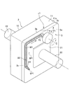
載置工程は、図2に示すように、ジャケット本体2に封止体3を載置する工程である。載置工程によって、周壁部11の端面11aと、封止体3の裏面3bとが突き合わされて第一突合せ部J1が形成される。第一突合せ部J1は、封止体3の周囲に沿って平面視矩形状に形成される。また、支柱12の端面12aと、封止体3の裏面3bとが突き合わされて第二突合せ部J2が形成される。周壁部11の側面11cと、封止体3の側面3cとは面一になる。なお、ジャケット本体2と封止体3とは溶接又は摩擦攪拌等により仮接合してもよい。
載置工程は、図2に示すように、ジャケット本体2に封止体3を載置する工程である。載置工程によって、周壁部11の端面11aと、封止体3の裏面3bとが突き合わされて第一突合せ部J1が形成される。第一突合せ部J1は、封止体3の周囲に沿って平面視矩形状に形成される。また、支柱12の端面12aと、封止体3の裏面3bとが突き合わされて第二突合せ部J2が形成される。周壁部11の側面11cと、封止体3の側面3cとは面一になる。なお、ジャケット本体2と封止体3とは溶接又は摩擦攪拌等により仮接合してもよい。
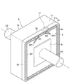
第一本接合工程は、図3及び図4に示すように、回転ツールFを用いて第一突合せ部J1を摩擦攪拌接合する工程である。第一本接合工程では、保持工程と、摩擦攪拌工程とを行う。保持工程は、一対の保持部22を備える挟持装置(治具)でジャケット本体2と封止体3とを両外側から押圧して挟持する。本実施形態では、保持部22と底部10との間、保持部22と封止体3との間にそれぞれ中間プレート21を介設している。保持部22は円柱状を呈し、その端面が中間プレート21,21にそれぞれ面接触する。中間プレート21を設けることで、保持部22の押圧力を分散させて、ジャケット本体2及び封止体3を確実に保持することができる。なお、中間プレート21は省略してもよい。
挟持装置の保持部22とジャケット本体2及び封止体3とは同期して回転又は平行移動する。つまり、当該挟持装置は、ジャケット本体2の底部10及び封止体3の表面3aを保持部22,22でそれぞれ押圧し挟持した状態で、ジャケット本体2及び封止体3を周方向に回転させるとともに、上下、左右及び前後方向に直線移動させることができる。
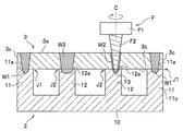
図4に示すように、回転ツールFは、連結部F1と、攪拌ピンF2とで構成されている。回転ツールFは、例えば工具鋼で形成されている。連結部F1は、摩擦攪拌装置(図示省略)の回転軸に連結される部位である。連結部F1は円柱状を呈し、ボルトが締結されるネジ孔(図示省略)が形成されている。
攪拌ピンF2は、連結部F1から垂下しており、連結部F1と同軸になっている。攪拌ピンF2は連結部F1から離間するにつれて先細りになっている。攪拌ピンF2の先端には、回転中心軸Cに対して垂直であり、かつ、平坦な平坦面が形成されている。
攪拌ピンF2は、連結部F1から垂下しており、連結部F1と同軸になっている。攪拌ピンF2は連結部F1から離間するにつれて先細りになっている。攪拌ピンF2の先端には、回転中心軸Cに対して垂直であり、かつ、平坦な平坦面が形成されている。
攪拌ピンF2の外周面には螺旋溝が刻設されている。本実施形態では、回転ツールFを右回転させるため、螺旋溝は、基端から先端に向かうにつれて左回りに形成されている。言い換えると、螺旋溝は、螺旋溝を基端から先端に向けてなぞると上から見て左回りに形成されている。
なお、回転ツールFを左回転させる場合は、螺旋溝を基端から先端に向かうにつれて右回りに形成することが好ましい。言い換えると、この場合の螺旋溝は、螺旋溝を基端から先端に向けてなぞると上から見て右回りに形成されている。螺旋溝をこのように設定することで、摩擦攪拌の際に塑性流動化した金属が螺旋溝によって攪拌ピンF2の先端側に導かれる。これにより、被接合金属部材(ジャケット本体2及び封止体3)の外部に溢れ出る金属の量を少なくすることができる。
なお、回転ツールFを左回転させる場合は、螺旋溝を基端から先端に向かうにつれて右回りに形成することが好ましい。言い換えると、この場合の螺旋溝は、螺旋溝を基端から先端に向けてなぞると上から見て右回りに形成されている。螺旋溝をこのように設定することで、摩擦攪拌の際に塑性流動化した金属が螺旋溝によって攪拌ピンF2の先端側に導かれる。これにより、被接合金属部材(ジャケット本体2及び封止体3)の外部に溢れ出る金属の量を少なくすることができる。
回転ツールFは、本実施形態では、水平方向及び上下方向に移動可能な摩擦攪拌装置に取り付けられている。なお、回転ツールFは、先端にスピンドルユニット等の回転駆動手段を備えたロボットアームに取り付けてもよい。
第一本接合工程では、まず、摩擦攪拌装置に取り付けられた回転ツールFを右回転させる。回転ツールFの位置は、本実施形態では摩擦攪拌装置に対して相対移動しないように固定されている。つまり、回転ツールFは摩擦攪拌装置に対して変位させず、回転ツールFに対してジャケット本体2及び封止体3側を移動させて摩擦攪拌を行う。
第一本接合工程では、まず、摩擦攪拌装置に取り付けられた回転ツールFを右回転させる。回転ツールFの位置は、本実施形態では摩擦攪拌装置に対して相対移動しないように固定されている。つまり、回転ツールFは摩擦攪拌装置に対して変位させず、回転ツールFに対してジャケット本体2及び封止体3側を移動させて摩擦攪拌を行う。
次に、図3及び図4に示すように、ジャケット本体2及び封止体3を保持する保持工程を行い、挟持装置(治具)を用いてジャケット本体2及び封止体3を保持する。そして、挟持装置を操作して、封止体3の表面3aに設定された開始位置SP1に回転ツールFを挿入して摩擦攪拌工程を行う。摩擦攪拌工程では、押入区間と、本区間と、離脱区間とを連続して摩擦攪拌を行う。
押入区間は、封止体3の表面3a上に設定された開始位置SP1から同じく封止体3の表面3a上に設定された中間点S1までの区間である。本区間は、中間点S1から周壁部11を一周して封止体3の表面3aの外縁部に沿って移動して中間点S1を通過した後、封止体3の表面3a上に設定された中間点S2まで至る区間である。離脱区間は、中間点S2から封止体3の表面3a上に設定された終了位置EP1までの区間である。中間点S1,S2は、封止体3の表面3aのうち、第一突合せ部J1に対応する位置に互いに離間して設定されている。また、開始位置SP1及び終了位置EP1は、封止体3の表面3aのうち、第一突合せ部J1に対応する位置よりも内側に設定されている。
押入区間は、封止体3の表面3a上に設定された開始位置SP1から同じく封止体3の表面3a上に設定された中間点S1までの区間である。本区間は、中間点S1から周壁部11を一周して封止体3の表面3aの外縁部に沿って移動して中間点S1を通過した後、封止体3の表面3a上に設定された中間点S2まで至る区間である。離脱区間は、中間点S2から封止体3の表面3a上に設定された終了位置EP1までの区間である。中間点S1,S2は、封止体3の表面3aのうち、第一突合せ部J1に対応する位置に互いに離間して設定されている。また、開始位置SP1及び終了位置EP1は、封止体3の表面3aのうち、第一突合せ部J1に対応する位置よりも内側に設定されている。
押入区間では、開始位置SP1に回転ツールFの回転中心軸Cが垂直となるように配置し、中間点S1に向けて相対移動させながら所定の深さとなるまで攪拌ピンF2を徐々に押入していく。回転ツールFが中間点S1に達したら、そのまま本区間に移行する。回転ツールFの移動軌跡には塑性化領域W1が形成される。押入区間から本区間に回転ツールFを移行させる際には、途中で回転ツールFが停止したり、移動速度が低下したりしないように、平面視直線状又は円弧状に回転ツールFを移動させることが好ましい。
本区間では、回転ツールFの回転中心軸Cと封止体3の表面3a及び周壁部11の端面11aとが垂直となるようにしつつ、所定の深さを維持した状態で、回転ツールFを封止体3の表面3aの外縁部に沿って相対移動させて当該外縁部を一周させる。ここで、「所定の深さ」とは、本区間において中間点S1から一周させて中間点S2に達するまでの回転ツールFの攪拌ピンF2を差し込む深さを言う。本実施形態では、回転ツールFの攪拌ピンF2の平坦面F3が、周壁部11の端面11aに達するように設定している。ジャケット本体2及び封止体3の角部においては、保持部22,22を回転させながら回転ツールFを相対移動させる。本区間では、攪拌ピンF2のみを周壁部11及び封止体3に接触させ、攪拌ピンF2の基端側は露出した状態で摩擦攪拌を行う。塑性化領域W1の始端と終端とをオーバーラップさせて回転ツールFが中間点S2に達したら、そのまま離脱区間に移行する。本区間から離脱区間に回転ツールFを移行させる際には、途中で回転ツールFが停止したり、移動速度が低下したりしないように、平面視直線状又は円弧状に回転ツールFを移動させることが好ましい。
離脱区間では、図5に示すように、中間点S2から終了位置EP1に相対移動させながら、攪拌ピンF2を徐々に引き抜いて終了位置EP1で離脱させる。第一本接合工程が終了したら、ジャケット本体2及び封止体3から挟持装置を離脱させる。
本実施形態では、本区間において、攪拌ピンF2の先端の平坦面F3が端面11aに達するように設定したが、攪拌ピンF2を封止体3のみと接触させた状態で摩擦攪拌接合を行ってもよい。この場合は、攪拌ピンF2と封止体3との摩擦熱によって第一突合せ部J1が塑性流動化して接合される。
本実施形態では、本区間において、攪拌ピンF2の先端の平坦面F3が端面11aに達するように設定したが、攪拌ピンF2を封止体3のみと接触させた状態で摩擦攪拌接合を行ってもよい。この場合は、攪拌ピンF2と封止体3との摩擦熱によって第一突合せ部J1が塑性流動化して接合される。
第二本接合工程は、図6に示すように、回転ツールFを用いて封止体3と支柱12とを摩擦攪拌接合する工程である。第二本接合工程では、回転ツールFを封止体3の表面3aから垂直に挿入し、第二突合せ部J2に沿って一周以上相対移動させた後、封止体3から回転ツールFを離脱させる。第二本接合工程では、攪拌ピンF2のみをジャケット本体2の支柱12及び封止体3に接触させ、攪拌ピンF2の基端側は露出させた状態で摩擦攪拌を行う。
本実施形態では、攪拌ピンF2の先端の平坦面F3が端面12a達するようにしているが、攪拌ピンF2と封止体3のみと接触させた状態で摩擦攪拌接合を行ってもよい。この場合は、攪拌ピンF2と封止体3との摩擦熱によって第二突合せ部J2が塑性流動化して接合される。なお、第二本接合工程は省略してもよい。
以上説明した第一実施形態に係る液冷ジャケットの製造方法によれば、ジャケット本体2の底部10と封止体3の表面3aとを一対の保持部22で両外側から保持した状態でジャケット本体2及び封止体3を回転又は移動させるため、第一本接合工程中に保持部22と回転ツールFとが干渉しない。つまり、ジャケット本体2と封止体3とを位置決めするための治具が、回転ツールFの移動ルート上に無いため回転ツールFの移動の妨げにならない。これにより、回転ツールFを駆動させるための装置等の付帯設備に費用を要せず、結果的に液冷ジャケット1の製造コストを低減することができる。
以上説明した第一実施形態に係る液冷ジャケットの製造方法によれば、ジャケット本体2の底部10と封止体3の表面3aとを一対の保持部22で両外側から保持した状態でジャケット本体2及び封止体3を回転又は移動させるため、第一本接合工程中に保持部22と回転ツールFとが干渉しない。つまり、ジャケット本体2と封止体3とを位置決めするための治具が、回転ツールFの移動ルート上に無いため回転ツールFの移動の妨げにならない。これにより、回転ツールFを駆動させるための装置等の付帯設備に費用を要せず、結果的に液冷ジャケット1の製造コストを低減することができる。
また、第二本接合工程を行うことで、接合強度を高めることができる。第二本接合工程において、攪拌ピンF2を支柱12に接触させれば、第二突合せ部J2をより確実に接合することができる。また、回転ツールFのみをジャケット本体2及び封止体3に挿入することにより、摩擦攪拌装置に作用する負荷を軽減することができる。
ここで、第一突合せ部J1上に開始位置SP1を設定し、回転ツールFを垂直に挿入して摩擦攪拌を行ってもよいが、この形態であると当該開始位置SP1に過大な摩擦熱が発生し、接合不良となるおそれがある。これに対し、本実施形態のように開始位置SP1を第一突合せ部J1よりも内側に設定し、第一突合せ部J1に向けて攪拌ピンF2を相対移動させながら徐々に押入することで、第一突合せ部J1上で摩擦熱が過大になるのを防ぐことができる。
ここで、第一突合せ部J1上に開始位置SP1を設定し、回転ツールFを垂直に挿入して摩擦攪拌を行ってもよいが、この形態であると当該開始位置SP1に過大な摩擦熱が発生し、接合不良となるおそれがある。これに対し、本実施形態のように開始位置SP1を第一突合せ部J1よりも内側に設定し、第一突合せ部J1に向けて攪拌ピンF2を相対移動させながら徐々に押入することで、第一突合せ部J1上で摩擦熱が過大になるのを防ぐことができる。
同様に、第一突合せ部J1上に終了位置EP1を設定し、当該終了位置EP1で回転ツールFを垂直に離脱させてもよいが、この形態であると終了位置EP1に過大な摩擦熱が発生し、接合不良となるおそれがある。これに対し、本実施形態のように終了位置EP1を第一突合せ部J1よりも内側に設定し、攪拌ピンF2を相対移動させながら第一突合せ部J1から徐々に引き抜くことで、第一突合せ部J1上で摩擦熱が過大になるのを防ぐことができる。
また、第一本接合工程では、封止体3の表面3a上での塑性化領域W1の始端と終端とをオーバーラップさせているため、気密性及び水密性を高めることができる。
なお、第一本接合工程は、第二本接合工程の後に行ってもよい。また、本実施形態の第一本接合工程では、回転ツールFの位置を摩擦攪拌装置に対して変位させないように設定したが、回転ツールFとジャケット本体2及び封止体3(挟持装置)とを両者とも移動させて摩擦攪拌接合を行ってもよい。例えば、回転ツールFをロボットアームに取り付けた場合は、当該ロボットアームとジャケット本体2及び封止体3(挟持装置)とを両者とも移動させて摩擦攪拌接合を行ってもよい。
なお、第一本接合工程は、第二本接合工程の後に行ってもよい。また、本実施形態の第一本接合工程では、回転ツールFの位置を摩擦攪拌装置に対して変位させないように設定したが、回転ツールFとジャケット本体2及び封止体3(挟持装置)とを両者とも移動させて摩擦攪拌接合を行ってもよい。例えば、回転ツールFをロボットアームに取り付けた場合は、当該ロボットアームとジャケット本体2及び封止体3(挟持装置)とを両者とも移動させて摩擦攪拌接合を行ってもよい。
また、本接合工程では、回転ツールFの回転速度を一定としてもよいが、可変させてもよい。本接合工程の押入区間において、開始位置SP1における回転ツールFの回転速度をV1とし、本区間における回転ツールFの回転速度をV2とすると、V1>V2としてもよい。回転速度のV2は、設定移動ルートL1における予め設定された一定の回転速度である。つまり、開始位置SP1では、回転速度を高く設定しておき、押入区間内で徐々に回転速度を低減させながら本区間に移行してもよい。
また、第一本接合工程の離脱区間において、本区間における回転ツールFの回転速度をV2、終了位置EP1において離脱させるときの回転ツールFの回転速度をV3とすると、V3>V2としてもよい。つまり、離脱区間に移行したら、終了位置EP1に向けて徐々に回転速度を上げながら封止体3から回転ツールFを離脱させてもよい。回転ツールFを封止体3に押し入れる際又は封止体3から離脱させる際に、前記のように設定することで、押入区間又は離脱区間時における少ない押圧力を、回転速度で補うことができるため、摩擦攪拌を好適に行うことができる。
[第二実施形態]
次に、本発明の第二実施形態に係る液冷ジャケットの製造方法ついて説明する。図7に示すように、第二実施形態では、支柱12に支柱段差部14が設けられている点で第一実施形態と主に相違する。第二実施形態では、第一実施形態と異なる部分を中心に説明する。
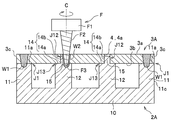
ジャケット本体2Aは、底部10と、周壁部11と、支柱12とで構成されている。底部10及び周壁部11は第一実施形態と同一である。支柱12の先端側には突出部15が形成されている。突出部15の形状は特に制限されないが、本実施形態では円柱状になっている。突出部15が形成されることにより、支柱12の先端には支柱段差部14が形成されている。支柱段差部14は、段差底面14aと、段差底面14aから立ち上がる段差側面14bが形成されている。段差底面14aは、周壁部11の端面11aと同じ高さ位置に形成されている。
次に、本発明の第二実施形態に係る液冷ジャケットの製造方法ついて説明する。図7に示すように、第二実施形態では、支柱12に支柱段差部14が設けられている点で第一実施形態と主に相違する。第二実施形態では、第一実施形態と異なる部分を中心に説明する。
ジャケット本体2Aは、底部10と、周壁部11と、支柱12とで構成されている。底部10及び周壁部11は第一実施形態と同一である。支柱12の先端側には突出部15が形成されている。突出部15の形状は特に制限されないが、本実施形態では円柱状になっている。突出部15が形成されることにより、支柱12の先端には支柱段差部14が形成されている。支柱段差部14は、段差底面14aと、段差底面14aから立ち上がる段差側面14bが形成されている。段差底面14aは、周壁部11の端面11aと同じ高さ位置に形成されている。
封止体3Aには、孔部4が形成されている。孔部4は、支柱12の突出部15に対応する位置に形成されている。孔部4は、突出部15が挿入可能な大きさで形成されている。
第二実施形態に係る液冷ジャケットの製造方法では、準備工程と、載置工程と、第一本接合工程と、第二本接合工程とを行う。準備工程は、ジャケット本体2A及び封止体3Aを準備する工程である。
載置工程は、図7に示すように、ジャケット本体2Aに封止体3Aを載置する工程である。載置工程では、周壁部11の端面11aに封止体3Aを載置しつつ、支柱12の突出部15を孔部4に挿入する。これにより、周壁部11の端面11aと封止体3の裏面3bとが突き合わされて第一突合せ部J1が形成される。また、段差側面14bと孔部4の孔壁4aとが突き合わされて段差側面突合せ部J12が形成される。また、段差底面14aと封止体3の裏面3bとが突き合わされて段差底面突合せ部J13が形成される。封止体3の厚さは適宜設定すればよいが、本実施形態では、段差側面14bの高さ寸法よりも大きくなっている。
第二実施形態に係る液冷ジャケットの製造方法では、準備工程と、載置工程と、第一本接合工程と、第二本接合工程とを行う。準備工程は、ジャケット本体2A及び封止体3Aを準備する工程である。
載置工程は、図7に示すように、ジャケット本体2Aに封止体3Aを載置する工程である。載置工程では、周壁部11の端面11aに封止体3Aを載置しつつ、支柱12の突出部15を孔部4に挿入する。これにより、周壁部11の端面11aと封止体3の裏面3bとが突き合わされて第一突合せ部J1が形成される。また、段差側面14bと孔部4の孔壁4aとが突き合わされて段差側面突合せ部J12が形成される。また、段差底面14aと封止体3の裏面3bとが突き合わされて段差底面突合せ部J13が形成される。封止体3の厚さは適宜設定すればよいが、本実施形態では、段差側面14bの高さ寸法よりも大きくなっている。
第一本接合工程は、第一実施形態と同じである。第二本接合工程では、回転ツールFの攪拌ピンF2のみを段差側面突合せ部J12及び段差底面突合せ部J13に挿入し、段差側面突合せ部J12に沿って一周以上回転ツールFを相対移動させる。本実施形態では、攪拌ピンF2の先端の平坦面F3が段差底面14aに達するように挿入深さを設定している。第二本接合工程において、回転ツールFの移動軌跡には塑性化領域W2が形成される。なお、第二本接合工程では、回転ツールFの先端の平坦面F3を段差底面14aに接触しないように設定してもよい。
以上説明した本実施形態に係る第二本接合工程によれば、支柱12の突出部15に封止体3Aの孔部4を挿入することで、ジャケット本体2Aと封止体3Aとの位置決めを容易に行うことができる。また、封止体3Aの板厚を、段差側面14bよりも大きく設定しているため、接合部が金属不足になるのを防ぐことができる。
以上本発明の実施形態について説明したが、本発明の趣旨に反しない範囲において適宜設計変更が可能である。
以上本発明の実施形態について説明したが、本発明の趣旨に反しない範囲において適宜設計変更が可能である。
1 液冷ジャケット
2 ジャケット本体
3 封止体
10 底部
11 周壁部
11a 端面
22 保持部
F 回転ツール
F2 攪拌ピン
J1 第一突合せ部
J2 第二突合せ部
J12 段差側面突合せ部
J13 段差底面突合せ部
SP1 開始位置
EP1 終了位置
W1 塑性化領域
2 ジャケット本体
3 封止体
10 底部
11 周壁部
11a 端面
22 保持部
F 回転ツール
F2 攪拌ピン
J1 第一突合せ部
J2 第二突合せ部
J12 段差側面突合せ部
J13 段差底面突合せ部
SP1 開始位置
EP1 終了位置
W1 塑性化領域
Claims (8)
- 底部、前記底部の周縁から立ち上がる周壁部及び前記底部から立ち上がる支柱を有するジャケット本体と、前記ジャケット本体の開口部を封止する封止体とで構成され、前記ジャケット本体と前記封止体とを摩擦攪拌で接合する液冷ジャケットの製造方法であって、
摩擦攪拌で用いる回転ツールの攪拌ピンの外周面は先細りとなるように傾斜しており、
前記ジャケット本体に前記封止体を載置することにより前記周壁部の端面と前記封止体の裏面とを重ね合わせて第一突合せ部を形成するとともに、前記支柱の端面と前記封止体の裏面とを重ね合わせて第二突合せ部を形成する載置工程と、
回転する前記回転ツールの前記攪拌ピンのみを前記封止体の表面から挿入し、前記攪拌ピンのみを前記封止体、又は前記周壁部及び前記封止体に接触させた状態で前記第一突合せ部に沿って所定の深さで前記周壁部の廻りに相対的に一周させて前記第一突合せ部を摩擦攪拌する第一本接合工程と、を含み、
前記第一本接合工程において、前記ジャケット本体の前記底部と前記封止体の表面とを両外側から一対の保持部で押圧して保持しつつ、前記保持部を用いて前記ジャケット本体及び前記封止体を回転又は平行移動させて前記ジャケット本体と前記封止体とを摩擦攪拌することを特徴とする液冷ジャケットの製造方法。 - 回転する前記回転ツールの前記攪拌ピンのみを前記封止体の表面から前記第二突合せ部に挿入し、前記攪拌ピンのみを前記封止体、又は前記封止体及び前記支柱に接触させた状態で前記第二突合せ部に対して所定の深さで相対的に移動させて前記第二突合せ部を摩擦攪拌する第二本接合工程と、をさらに含むことを特徴とする請求項1に記載の液冷ジャケットの製造方法。
- 底部、前記底部の周縁から立ち上がる周壁部及び前記底部から立ち上がる支柱を有するジャケット本体と、前記支柱の先端が挿入される孔部を備えるとともに前記ジャケット本体の開口部を封止する封止体とで構成され、前記ジャケット本体と前記封止体とを摩擦攪拌で接合する液冷ジャケットの製造方法であって、
摩擦攪拌で用いる回転ツールの攪拌ピンの外周面は先細りとなるように傾斜しており、
前記支柱の先端に段差底面と当該段差底面から立ち上がる段差側面とを有する支柱段差部を形成するとともに、前記支柱の段差底面を前記周壁部の端面と同一の高さ位置に形成し、前記封止体の厚みを前記段差側面よりも大きく形成する準備工程と、
前記ジャケット本体に前記封止体を載置することにより前記周壁部の端面と前記封止体の裏面とを重ね合わせて第一突合せ部を形成するとともに、前記支柱の段差側面と前記孔部の孔壁とを突き合せて段差側面突合せ部を形成し、前記支柱の段差底面と前記封止体の裏面とを重ね合わせて段差底面突合せ部を形成する載置工程と、
回転する前記回転ツールの前記攪拌ピンのみを前記封止体の表面から挿入し、前記攪拌ピンのみを前記封止体、又は前記周壁部及び前記封止体に接触させた状態で前記第一突合せ部に沿って所定の深さで前記周壁部の廻りに相対的に一周させて前記第一突合せ部を摩擦攪拌する第一本接合工程と、を含み、
前記第一本接合工程において、前記ジャケット本体の前記底部と前記封止体の表面とを両外側から一対の保持部で押圧して保持しつつ、前記保持部を用いて前記ジャケット本体及び前記封止体を回転又は平行移動させて前記ジャケット本体と前記封止体とを摩擦攪拌することを特徴とする液冷ジャケットの製造方法。 - 回転する前記回転ツールの前記攪拌ピンのみを封止体の表面から前記段差側面突合せ部に挿入し、前記攪拌ピンのみを前記封止体及び前記支柱に接触させた状態で前記段差側面突合せ部に沿って所定の深さで相対的に移動させて前記段差側面突合せ部を摩擦攪拌する第二本接合工程と、をさらに含むことを特徴とする請求項3に記載の液冷ジャケットの製造方法。
- 前記第一本接合工程後に前記第二本接合工程を行うことを特徴とする請求項2又は請求項4に記載の液冷ジャケットの製造方法。
- 前記第二本接合工程後に前記第一本接合工程を行うことを特徴とする請求項2又は請求項4に記載の液冷ジャケットの製造方法。
- 前記第一本接合工程では、所定の回転速度で前記攪拌ピンを回転させて摩擦攪拌を行い、
前記第一本接合工程において前記攪拌ピンを引き抜くとき、前記所定の回転速度よりも徐々に回転速度を上げながら前記回転ツールを終了位置まで相対移動させることを特徴とする請求項1又は請求項3に記載の液冷ジャケットの製造方法。 - 前記第一本接合工程では、所定の回転速度で前記攪拌ピンを回転させて摩擦攪拌を行い、
前記第一本接合工程において前記攪拌ピンを挿入するとき、前記所定の回転速度よりも高い速度で前記攪拌ピンを回転させた状態で挿入し、徐々に回転速度を下げながら前記第一突合せ部まで相対移動させることを特徴とする請求項1又は請求項3に記載の液冷ジャケットの製造方法。
Priority Applications (1)
| Application Number | Priority Date | Filing Date | Title |
|---|---|---|---|
| CN202080080507.6A CN114728369A (zh) | 2019-11-21 | 2020-03-26 | 液冷套的制造方法 |
Applications Claiming Priority (2)
| Application Number | Priority Date | Filing Date | Title |
|---|---|---|---|
| JP2019210694A JP2021079421A (ja) | 2019-11-21 | 2019-11-21 | 液冷ジャケットの製造方法 |
| JP2019-210694 | 2019-11-21 |
Publications (1)
| Publication Number | Publication Date |
|---|---|
| WO2021100221A1 true WO2021100221A1 (ja) | 2021-05-27 |
Family
ID=75963677
Family Applications (1)
| Application Number | Title | Priority Date | Filing Date |
|---|---|---|---|
| PCT/JP2020/013823 Ceased WO2021100221A1 (ja) | 2019-11-21 | 2020-03-26 | 液冷ジャケットの製造方法 |
Country Status (3)
| Country | Link |
|---|---|
| JP (1) | JP2021079421A (ja) |
| CN (1) | CN114728369A (ja) |
| WO (1) | WO2021100221A1 (ja) |
Cited By (1)
| Publication number | Priority date | Publication date | Assignee | Title |
|---|---|---|---|---|
| US20210324889A1 (en) * | 2018-10-25 | 2021-10-21 | Nhk Spring Co., Ltd. | Joined body |
Citations (4)
| Publication number | Priority date | Publication date | Assignee | Title |
|---|---|---|---|---|
| WO2008041380A1 (en) * | 2006-10-02 | 2008-04-10 | Nippon Light Metal Company, Ltd. | Method of welding and method of friction stir |
| WO2019082439A1 (ja) * | 2017-10-27 | 2019-05-02 | 日本軽金属株式会社 | 液冷ジャケットの製造方法 |
| WO2019082435A1 (ja) * | 2017-10-27 | 2019-05-02 | 日本軽金属株式会社 | 液冷ジャケットの製造方法 |
| JP2019188433A (ja) * | 2018-04-24 | 2019-10-31 | アイシン精機株式会社 | 摩擦攪拌接合方法 |
Family Cites Families (5)
| Publication number | Priority date | Publication date | Assignee | Title |
|---|---|---|---|---|
| WO2017033923A1 (ja) * | 2015-08-26 | 2017-03-02 | 日本軽金属株式会社 | 接合方法、液冷ジャケットの製造方法及び液冷ジャケット |
| JP2018176208A (ja) * | 2017-04-10 | 2018-11-15 | 日本軽金属株式会社 | 液冷ジャケットの製造方法 |
| JP6766956B2 (ja) * | 2017-04-18 | 2020-10-14 | 日本軽金属株式会社 | 液冷ジャケットの製造方法 |
| JP6834925B2 (ja) * | 2017-12-05 | 2021-02-24 | 日本軽金属株式会社 | 液冷ジャケットの製造方法 |
| JP2019195825A (ja) * | 2018-05-09 | 2019-11-14 | 日本軽金属株式会社 | 接合方法 |
-
2019
- 2019-11-21 JP JP2019210694A patent/JP2021079421A/ja active Pending
-
2020
- 2020-03-26 WO PCT/JP2020/013823 patent/WO2021100221A1/ja not_active Ceased
- 2020-03-26 CN CN202080080507.6A patent/CN114728369A/zh active Pending
Patent Citations (4)
| Publication number | Priority date | Publication date | Assignee | Title |
|---|---|---|---|---|
| WO2008041380A1 (en) * | 2006-10-02 | 2008-04-10 | Nippon Light Metal Company, Ltd. | Method of welding and method of friction stir |
| WO2019082439A1 (ja) * | 2017-10-27 | 2019-05-02 | 日本軽金属株式会社 | 液冷ジャケットの製造方法 |
| WO2019082435A1 (ja) * | 2017-10-27 | 2019-05-02 | 日本軽金属株式会社 | 液冷ジャケットの製造方法 |
| JP2019188433A (ja) * | 2018-04-24 | 2019-10-31 | アイシン精機株式会社 | 摩擦攪拌接合方法 |
Cited By (2)
| Publication number | Priority date | Publication date | Assignee | Title |
|---|---|---|---|---|
| US20210324889A1 (en) * | 2018-10-25 | 2021-10-21 | Nhk Spring Co., Ltd. | Joined body |
| US12338852B2 (en) * | 2018-10-25 | 2025-06-24 | Nhk Spring Co., Ltd. | Joined body |
Also Published As
| Publication number | Publication date |
|---|---|
| JP2021079421A (ja) | 2021-05-27 |
| CN114728369A (zh) | 2022-07-08 |
Similar Documents
| Publication | Publication Date | Title |
|---|---|---|
| JP2019037987A (ja) | 液冷ジャケットの製造方法 | |
| JP2019037986A (ja) | 液冷ジャケットの製造方法 | |
| WO2021100222A1 (ja) | 液冷ジャケットの製造方法 | |
| WO2021100221A1 (ja) | 液冷ジャケットの製造方法 | |
| WO2020059198A1 (ja) | 液冷ジャケットの製造方法 | |
| JP2020171957A (ja) | 液冷ジャケットの製造方法 | |
| WO2021149271A1 (ja) | 液冷ジャケットの製造方法 | |
| JP2018065164A (ja) | 中空容器の製造方法 | |
| JP2021133407A (ja) | 液冷ジャケットの製造方法 | |
| JP2021094574A (ja) | 液冷ジャケットの製造方法 | |
| JP2021112748A (ja) | 液冷ジャケットの製造方法 | |
| JP2021133403A (ja) | 液冷ジャケットの製造方法 | |
| WO2020213195A1 (ja) | 液冷ジャケットの製造方法 | |
| JP2021154293A (ja) | 液冷ジャケットの製造方法 | |
| JP6451503B2 (ja) | 接合方法 | |
| JP2021133405A (ja) | 液冷ジャケットの製造方法 | |
| JP2021133408A (ja) | 液冷ジャケットの製造方法 | |
| JP2021115587A (ja) | 液冷ジャケットの製造方法 | |
| JP2021154313A (ja) | 液冷ジャケットの製造方法 | |
| JP2021154300A (ja) | 液冷ジャケットの製造方法 | |
| JP2021186856A (ja) | 液冷ジャケットの製造方法 | |
| WO2020213197A1 (ja) | 液冷ジャケットの製造方法 | |
| JP2021186869A (ja) | 液冷ジャケットの製造方法 | |
| JP2020171958A (ja) | 液冷ジャケットの製造方法 | |
| JP2021186858A (ja) | 液冷ジャケットの製造方法 |
Legal Events
| Date | Code | Title | Description |
|---|---|---|---|
| 121 | Ep: the epo has been informed by wipo that ep was designated in this application |
Ref document number: 20889942 Country of ref document: EP Kind code of ref document: A1 |
|
| NENP | Non-entry into the national phase |
Ref country code: DE |
|
| 122 | Ep: pct application non-entry in european phase |
Ref document number: 20889942 Country of ref document: EP Kind code of ref document: A1 |