WO2021095699A1 - レーザ加工装置 - Google Patents
レーザ加工装置 Download PDFInfo
- Publication number
- WO2021095699A1 WO2021095699A1 PCT/JP2020/041786 JP2020041786W WO2021095699A1 WO 2021095699 A1 WO2021095699 A1 WO 2021095699A1 JP 2020041786 W JP2020041786 W JP 2020041786W WO 2021095699 A1 WO2021095699 A1 WO 2021095699A1
- Authority
- WO
- WIPO (PCT)
- Prior art keywords
- laser
- light
- processing
- wavelength
- analysis
- Prior art date
- Legal status (The legal status is an assumption and is not a legal conclusion. Google has not performed a legal analysis and makes no representation as to the accuracy of the status listed.)
- Ceased
Links
Images


Classifications
-
- B—PERFORMING OPERATIONS; TRANSPORTING
- B23—MACHINE TOOLS; METAL-WORKING NOT OTHERWISE PROVIDED FOR
- B23K—SOLDERING OR UNSOLDERING; WELDING; CLADDING OR PLATING BY SOLDERING OR WELDING; CUTTING BY APPLYING HEAT LOCALLY, e.g. FLAME CUTTING; WORKING BY LASER BEAM
- B23K26/00—Working by laser beam, e.g. welding, cutting or boring
- B23K26/02—Positioning or observing the workpiece, e.g. with respect to the point of impact; Aligning, aiming or focusing the laser beam
- B23K26/06—Shaping the laser beam, e.g. by masks or multi-focusing
- B23K26/0604—Shaping the laser beam, e.g. by masks or multi-focusing by a combination of beams
- B23K26/0608—Shaping the laser beam, e.g. by masks or multi-focusing by a combination of beams in the same heat affected zone [HAZ]
-
- B—PERFORMING OPERATIONS; TRANSPORTING
- B23—MACHINE TOOLS; METAL-WORKING NOT OTHERWISE PROVIDED FOR
- B23K—SOLDERING OR UNSOLDERING; WELDING; CLADDING OR PLATING BY SOLDERING OR WELDING; CUTTING BY APPLYING HEAT LOCALLY, e.g. FLAME CUTTING; WORKING BY LASER BEAM
- B23K26/00—Working by laser beam, e.g. welding, cutting or boring
- B23K26/02—Positioning or observing the workpiece, e.g. with respect to the point of impact; Aligning, aiming or focusing the laser beam
- B23K26/03—Observing, e.g. monitoring, the workpiece
- B23K26/032—Observing, e.g. monitoring, the workpiece using optical means
-
- G—PHYSICS
- G01—MEASURING; TESTING
- G01N—INVESTIGATING OR ANALYSING MATERIALS BY DETERMINING THEIR CHEMICAL OR PHYSICAL PROPERTIES
- G01N21/00—Investigating or analysing materials by the use of optical means, i.e. using sub-millimetre waves, infrared, visible or ultraviolet light
- G01N21/17—Systems in which incident light is modified in accordance with the properties of the material investigated
- G01N21/25—Colour; Spectral properties, i.e. comparison of effect of material on the light at two or more different wavelengths or wavelength bands
- G01N21/31—Investigating relative effect of material at wavelengths characteristic of specific elements or molecules, e.g. atomic absorption spectrometry
-
- B—PERFORMING OPERATIONS; TRANSPORTING
- B23—MACHINE TOOLS; METAL-WORKING NOT OTHERWISE PROVIDED FOR
- B23K—SOLDERING OR UNSOLDERING; WELDING; CLADDING OR PLATING BY SOLDERING OR WELDING; CUTTING BY APPLYING HEAT LOCALLY, e.g. FLAME CUTTING; WORKING BY LASER BEAM
- B23K26/00—Working by laser beam, e.g. welding, cutting or boring
- B23K26/20—Bonding
- B23K26/21—Bonding by welding
- B23K26/24—Seam welding
- B23K26/244—Overlap seam welding
-
- B—PERFORMING OPERATIONS; TRANSPORTING
- B23—MACHINE TOOLS; METAL-WORKING NOT OTHERWISE PROVIDED FOR
- B23K—SOLDERING OR UNSOLDERING; WELDING; CLADDING OR PLATING BY SOLDERING OR WELDING; CUTTING BY APPLYING HEAT LOCALLY, e.g. FLAME CUTTING; WORKING BY LASER BEAM
- B23K26/00—Working by laser beam, e.g. welding, cutting or boring
- B23K26/20—Bonding
- B23K26/32—Bonding taking account of the properties of the material involved
- B23K26/323—Bonding taking account of the properties of the material involved involving parts made of dissimilar metallic material
-
- G—PHYSICS
- G01—MEASURING; TESTING
- G01N—INVESTIGATING OR ANALYSING MATERIALS BY DETERMINING THEIR CHEMICAL OR PHYSICAL PROPERTIES
- G01N2201/00—Features of devices classified in G01N21/00
- G01N2201/06—Illumination; Optics
- G01N2201/061—Sources
- G01N2201/06113—Coherent sources; lasers
-
- G—PHYSICS
- G01—MEASURING; TESTING
- G01N—INVESTIGATING OR ANALYSING MATERIALS BY DETERMINING THEIR CHEMICAL OR PHYSICAL PROPERTIES
- G01N2201/00—Features of devices classified in G01N21/00
- G01N2201/06—Illumination; Optics
- G01N2201/062—LED's
Definitions
- the present disclosure relates to a laser processing apparatus, and particularly to a laser processing apparatus that processes a composite material composed of two or more kinds of materials by laser light.
- FIG. 1 of Patent Document 1 shows a multi-wavelength laser having a semiconductor laser element that emits a red laser beam and a semiconductor laser element that emits an infrared laser beam as a light source used in this type of laser processing apparatus.
- the light emitting device is disclosed.
- the laser beam can be applied to the predetermined machining position of the object to be machined by determining the position where the object to be machined is placed on the table in advance. ..
- the object to be processed when the object to be processed is placed on the processing table, the object to be processed is displaced from a predetermined position, or the outer shape of the object to be processed is uneven, and there are individual differences (individual variation) in the object to be processed. If this happens, an appropriate laser beam will not be applied to a predetermined processing position of the object to be processed, which may cause processing defects.
- the wavelength of the laser beam may be switched at the change point of the material.
- the composite material may be used. Laser light of an appropriate wavelength is not irradiated to each of the plurality of materials, resulting in processing defects. As a result, the processing quality is lowered and the throughput is lowered.
- the present disclosure has been made to solve such a problem, and an object of the present disclosure is to provide a laser processing apparatus or the like capable of realizing high-quality laser processing with high throughput.
- one aspect of the laser processing apparatus is a laser processing apparatus that processes an object by laser light, and a first laser light having a peak wavelength of the first wavelength is emitted.
- the drive control unit is provided with a drive control unit for driving each of the laser oscillators of the above, and an analysis unit that acquires signal light from the object and adjusts processing conditions of the object based on the acquired signal light.
- the unit changes the intensity of at least one of the first laser beam and the second laser beam by driving the first laser oscillator and the second laser oscillator according to the processing conditions.
- the object is irradiated with at least one of the first laser beam and the second laser beam.
- high-quality laser machining can be realized with high throughput.
- FIG. 1 (a) is a diagram for explaining a state in which a composite material is processed by irradiating a composite material with laser light using a laser processing device
- FIG. 1 (b) is a diagram for explaining a state in which the composite material is processed. It is a top view of (a) in the XY coordinate system of the apparatus.
- FIG. 2 is a diagram showing a state in which the position shift of the composite material occurs when the composite material is laser-machined according to a predetermined recipe.
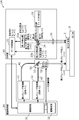
- FIG. 3 is a block diagram showing a configuration of the laser processing apparatus according to the first embodiment.
- FIG. 4 is a flowchart of the laser machining method according to the first embodiment.
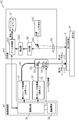
- FIG. 5 is a block diagram showing the configuration of the laser processing apparatus according to the second embodiment.
- FIG. 6 is a flowchart of the laser machining method according to the second embodiment.
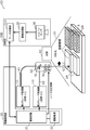
- FIG. 7 is a block diagram showing the configuration of the laser processing apparatus according to the third embodiment.
- FIG. 8 is a flowchart of the laser machining method according to the third embodiment.
- FIG. 9 is a block diagram showing the configuration of the laser processing apparatus according to the fourth embodiment.
- FIG. 10 is a flowchart of the laser machining method according to the fourth embodiment.
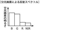
- FIG. 11 is a diagram showing an example of a reflection spectrum obtained from the signal light of the object to be processed in the fourth embodiment.
- FIG. 12 is a diagram showing an example of a data group of reflection spectra stored in a database in the fourth embodiment.
- FIG. 13 is a block diagram showing the configuration of the laser processing apparatus according to the fifth embodiment.
- FIG. 14 is a diagram showing an example of a two-dimensional image captured by the image sensor in the fifth embodiment.
- FIG. 15 is a flowchart of the laser machining method according to the fifth embodiment.
- FIG. 16 is a diagram showing an example of the layout of one pixel of the image sensor according to the fifth embodiment.
- FIG. 17 is a diagram showing another example of the layout of one pixel of the image sensor according to the fifth embodiment.
- FIG. 18 is a diagram showing an example of a reflection spectrum by spectroscopic pixels in the fifth embodiment.
- FIG. 19 is a block diagram showing the configuration of the laser processing apparatus according to the sixth embodiment.
- FIG. 20 is a flowchart of the laser machining method according to the sixth embodiment.
- FIG. 21 is a diagram showing an example of the light emission intensity with respect to the processing depth imaged by the image sensor in the sixth embodiment.
- FIG. 22 is a block diagram showing a
- a laser processing device capable of emitting laser light of multiple wavelengths is used to change the material. It is conceivable to perform laser processing by switching the wavelength of the laser beam. For example, as shown in FIGS. 1A and 1B, a first portion 2a composed of a first material and a second portion composed of a second material different from the first material.
- the first portions 2a and the second By stacking two composite materials 2X in which 2b and 2b are connected side by side in a plan view and irradiating a line-shaped welded region at a predetermined processing position with a laser beam, the first portions 2a and the second When the two composite materials 2X are joined by welding the two parts 2b to each other, the light absorption rate is different between the first part 2a and the second part 2b, so that the welding part corresponding to the first part 2a is the first.
- the first laser beam L1 having a wavelength suitable for the first material constituting the first portion 2a is irradiated, and at the welding portion corresponding to the second portion 2b, the second material constituting the second portion 2b is used.
- a second laser beam L2 having a suitable wavelength is irradiated.
- the composite material 2X when a composite metal plate in which the first material constituting the first portion 2a is made of aluminum and the second material constituting the second portion 2b is made of copper is used as the composite material 2X. Since aluminum has a high light absorption rate for infrared light and copper has a high absorption rate for blue light, the first laser light L1 is used as infrared laser light and the second laser light L2 is used as blue laser light. Then, the boundary between the first portion 2a and the second portion 2b is set as the laser switching position, and the laser light irradiating the composite material 2X at this laser switching position is changed from the first laser light L1 to the second laser light L2. Switch.
- processing conditions such as which material is arranged at which position and what kind of laser light is irradiated should be created in advance. Therefore, it is possible to select a laser beam having a wavelength suitable for each material at an arbitrary position where each of the plurality of different materials exists. For example, as shown in FIG. 1B, when the composite material 2X arranged on the processing table is laser-welded by the laser processing apparatus, the composite material is used in the XY coordinate system on the laser processing apparatus (or laser processing system).
- the position where the 2X is arranged on the processing table is determined in advance, the coordinate range of the welding region is determined in advance from the position where the first portion 2a and the second portion 2b exist, and the first portion 2a is determined.
- the laser condition that the laser light irradiating the composite material 2X is switched from the first laser light L1 to the second laser light L2 at the laser switching coordinates is determined in advance with the boundary between the laser beam and the second portion 2b as the laser switching coordinates. Therefore, the welding region and the laser condition for the composite material 2X are prepared in advance as a recipe.
- the laser light irradiating the composite material 2X with the laser switching coordinates can be switched from the first laser light L1 to the second laser light L2 based on this recipe. It is possible to irradiate the second portion 2b with a laser beam suitable for each material. Therefore, it is possible to realize laser machining with high throughput and low spatter (that is, high machining quality).
- the object to be machined may shift from a predetermined position when the object to be machined is placed on the machining table, or the outer shape of the object to be machined may be displaced.
- the welded region in the first portion 2a is irradiated with the laser beam having an appropriate wavelength, but the welded region in the second portion 2b is irradiated with the laser beam having an inappropriate wavelength.
- the second part 2b located between the actual boundary between the first part 2a and the second part 2b and the predetermined laser switching coordinates is the material of the first part 2a.
- the first laser beam L1 suitable for the above is irradiated. As a result, it becomes impossible to irradiate the laser beam having an appropriate wavelength over the entire welding region (machining position) of the composite material 2X.
- the outer shape variation and installation position of each object to be processed are measured, and the switching coordinates of the wavelength of the laser light are appropriately set for each object to be processed. It is necessary to create an individual recipe corresponding to the above, and as a result, the throughput is reduced.
- the present disclosure has been made to solve such a problem, and provides a laser processing apparatus and the like capable of realizing high-quality laser processing with high throughput even in the case of laser processing a composite material.
- the purpose is to do.
- each figure is a schematic view and is not necessarily exactly illustrated. Therefore, the scales and the like do not always match in each figure.
- substantially the same configuration is designated by the same reference numerals, and duplicate description will be omitted or simplified.
- FIG. 3 is a block diagram showing the configuration of the laser processing apparatus 1 according to the first embodiment.
- the laser processing apparatus 1 is an apparatus for processing an object 2 to be processed by a laser beam. That is, the laser processing apparatus 1 performs laser processing on the processing target object 2 by irradiating the processing target object 2 with the laser light.
- the laser processing by the laser processing apparatus 1 is, for example, welding, cutting, drilling, or the like.
- the processing object 2 is an object processed by the laser processing apparatus 1. That is, the processing target object 2 is an irradiation target object to which the laser beam is irradiated.
- the processing object 2 is the composite material 2X shown in FIG. 1 and is arranged on the processing table 3.
- the processing table 3 is a stage on which the processing object 2 is placed.
- the processing table 3 is configured to be movable in two axial directions, an X-axis direction and a Y-axis direction, which are orthogonal to each other.
- the processing table 3 may be further configured to be movable in the Z-axis direction (for example, the vertical direction) orthogonal to both the X-axis and the Y-axis, or can be rotated about a predetermined ⁇ -axis. It may be configured.
- the laser processing apparatus 1 includes a first laser oscillator 11, a second laser oscillator 12, a drive control unit 20, and an analysis unit 30.
- the first laser oscillator 11 emits a first laser beam L1 having a peak wavelength of the first wavelength ( ⁇ 1) as a processing laser beam for laser machining the object 2 to be machined.
- the second laser oscillator 12 is a second laser beam having a peak wavelength different from the first wavelength ( ⁇ 2 ⁇ ⁇ 1) as a processing laser beam for laser machining the object 2 to be machined. Emit L2.
- the first laser oscillator 11 and the second laser oscillator 12 are composed of, for example, semiconductor laser elements that emit laser light.
- the second wavelength of the second laser beam L2 emitted by the second laser oscillator 12 is larger than the first wavelength of the first laser beam L1 emitted by the first laser oscillator 11. Short ( ⁇ 1> ⁇ 2).
- the first wavelength of the first laser beam L1 is a wavelength equal to or higher than near infrared rays. Specifically, the first wavelength of the first laser beam L1 is a wavelength of 800 nm or more.
- the second wavelength of the second laser beam L2 is a wavelength equal to or lower than that of visible light. Specifically, the second wavelength of the second laser beam L2 is a wavelength of 800 nm or less.
- the material 2X aluminum has a high light absorption rate for infrared light and copper has a high absorption rate for blue light. Therefore, the first laser light L1 is used as infrared laser light and the second laser light L2 is blue. It is good to use laser light.
- the material combination of the composite material 2X is not limited to aluminum and copper, and may be a combination of aluminum and gold or nickel. The material combination of the composite material 2X may be a combination of dissimilar metals having different light absorption rates.
- the first laser beam L1 emitted from the first laser oscillator 11 irradiates the processing object 2 arranged on the processing table 3.
- the second laser beam L2 emitted from the second laser oscillator 12 irradiates the processing object 2 arranged on the processing table 3.
- the first laser beam L1 and the second laser beam L2 irradiate the processing position of the object to be processed 2.
- an optical system such as a lens or a mirror suitable for guiding and condensing the laser beam toward the processing position is arranged.
- the drive control unit 20 drives each of the first laser oscillator 11 and the second laser oscillator 12.
- the drive control unit 20 drives the first laser oscillator 11 to light up to emit the first laser beam L1 from the first laser oscillator 11 or drives the first laser oscillator 11 to turn off. By doing so, it is possible to prevent the first laser beam L1 from being emitted. That is, the drive control unit 20 can start or stop the emission of the first laser beam L1 by driving the first laser oscillator 11. Further, the drive control unit 20 can change the intensity (output) of the first laser beam L1 by driving the first laser oscillator 11.
- the drive control unit 20 emits the second laser beam L2 from the second laser oscillator 12 by driving the second laser oscillator 12 on, or drives the second laser oscillator 12 to turn off. It is possible to prevent the second laser beam L2 from being emitted. That is, the drive control unit 20 can start or stop the emission of the second laser beam L2 by driving the second laser oscillator 12. Further, the drive control unit 20 can change the intensity (output) of the second laser beam L2 by driving the second laser oscillator 12.
- the analysis unit 30 acquires the signal light from the processing object 2 and adjusts the processing conditions of the processing object 2 based on the acquired signal light. Specifically, the analysis unit 30 acquires the material information of the processing object 2 by analyzing the signal light obtained from the processing object 2, and laser-machines the processing object 2 based on the acquired material information. Adjust the machining conditions (laser machining conditions). For example, the analysis unit 30 includes a mechanism such as a photodetector that receives signal light from the object to be processed 2, and a control circuit for adjusting the processing conditions of the object 2 to be processed according to the intensity of the received signal light. Has a control device.
- the analysis unit 30 analyzes the signal light from the first portion 2a so that the first portion 2a is composed of the first material.
- the material information is acquired, and the processing conditions for laser processing the first portion 2a of the processing object 2 are adjusted based on the acquired material information.
- the analysis unit 30 selects the first laser beam L1 as the laser beam suitable for the first material of the first portion 2a of the object to be processed 2, and determines the intensity of the first laser beam L1.
- the machining conditions are adjusted by setting.
- the analysis unit 30 acquires the material information that the second part 2b is composed of the second material by analyzing the signal light from the second part 2b, and uses the acquired material information as the material information.
- the machining conditions for laser machining the second portion 2b of the object to be machined 2 are adjusted.
- the analysis unit 30 selects the second laser beam L2 as the laser beam suitable for the second material of the second portion 2b of the object to be processed 2, and determines the intensity of the second laser beam L2.
- the machining conditions are adjusted by setting.
- the drive control unit 20 drives the first laser oscillator 11 and the second laser oscillator 12 according to the processing conditions obtained by the analysis unit 30.
- the intensity of at least one of the first laser beam L1 and the second laser beam L2 is changed to irradiate the workpiece 2 with at least one of the first laser beam L1 and the second laser beam L2.
- the drive control unit 20 processes the machining object 2 adjusted based on the material information of the machining object 2 obtained by analyzing the signal light from the machining object 2 by the analysis unit 30.
- the intensity of each of the first laser beam L1 and the second laser beam L2 is changed according to the conditions to selectively irradiate the workpiece 2 with the first laser beam L1 and the second laser beam L2. I'm letting you. That is, the drive control unit 20 switches the laser beam so that the laser beam suitable for the material of the processing object 2 is irradiated according to the material information of the processing object 2 obtained by the analysis unit 30.
- the drive control unit 20 controls the drive of the first laser oscillator 11 and the second laser oscillator 12 to irradiate the workpiece 2 with the laser light from the first laser beam L1 to the second laser. It switches to the light L2 or switches from the second laser light L2 to the first laser light L1.
- the analysis unit 30 uses the first laser beam as a processing condition suitable for the first material of the first portion 2a. Since L1 and its intensity are adjusted, the drive control unit 20 uses the first laser beam L1 suitable for the first material of the first portion 2a according to the processing conditions adjusted by the analysis unit 30. The first laser oscillator 11 is turned on and the second laser oscillator 12 is turned off so that the portion 2a is irradiated. Similarly, when the second portion 2b is laser-processed, the analysis unit 30 adjusts the second laser beam L2 and its intensity as processing conditions suitable for the second material of the second portion 2b, and thus drives the second portion 2b.
- the control unit 20 is so that the second portion 2b is irradiated with the second laser beam L2 suitable for the second material of the second portion 2b according to the processing conditions adjusted by the analysis unit 30.
- the laser oscillator 12 of the above is turned on and the first laser oscillator 11 is turned off.
- FIG. 4 is a flowchart of the laser machining method according to the first embodiment.
- the object to be processed 2 is placed on the processing table 3 (step S11).
- the processing target 2 to be laser-processed by the laser processing apparatus 1 is arranged on the processing table 3.
- the processing target 2 to be laser-processed by the laser processing apparatus 1 is arranged on the processing table 3.
- the processing position of the object to be processed 2 is irradiated with light (step S12).
- the processing position of the processing object 2 is irradiated with light for receiving the signal light from the processing position of the processing object 2.
- the processing object 2 is irradiated with laser light, LED light, illumination light, or the like.
- Step S12 is performed by the analysis unit 30. Therefore, the analysis unit 30 has a mechanism for irradiating the processing position of the processing object 2 with light.
- Step S13 the signal light from the processing position of the processing object 2 is received (step S13).
- the reflected light of the light applied to the processing position of the processing object 2 is received as a signal light.
- Step S13 can be performed by a photodetector or the like included in the analysis unit 30.
- the processing conditions for performing laser processing are adjusted according to the received signal light (step S14). Specifically, as the processing conditions, the intensities (outputs) of the first laser beam L1 emitted from the first laser oscillator 11 and the second laser beam L2 emitted from the second laser oscillator 12 are determined. .. Step S14 can be performed by a control device or the like included in the analysis unit 30.
- the intensity of the laser beam is changed from the adjusted processing conditions (step S15). Specifically, at least of the first laser beam L1 emitted from the first laser oscillator 11 and the second laser beam L2 emitted from the second laser oscillator 12 according to the processing conditions adjusted in step S14. Change the strength of one. Step S15 is performed by the drive control unit 20.
- the object to be processed 2 is irradiated with laser light (step S16). Specifically, according to the respective intensities of the first laser beam L1 and the second laser beam L2 set in step S15, the first laser beam L1 is emitted from the first laser oscillator 11 to be processed. The processing position of the object 2 is irradiated with the first laser beam L1, or the second laser beam L2 is emitted from the second laser oscillator 12 to irradiate the processing position of the object 2 with the second laser beam L2. To do. Step S16 is performed by the drive control unit 20.
- the laser processing method according to this embodiment can be performed by the above procedure.
- the laser machining can be completed by repeating steps S13 to S16 only once. Specifically, after performing steps S13 and S14 to acquire signal light of all machining positions with respect to the machining target 2, and first adjusting all machining conditions of the machining positions of the machining target 2. Based on the adjusted processing conditions, steps S15 and S16 are performed to irradiate the first laser beam L1 and the second laser beam L2 to perform laser processing. That is, after the recipes of the processing conditions of all the processing positions of the processing object 2 are first created, laser processing is performed based on the created recipes.
- steps S13 to S16 may be repeated a plurality of times. That is, laser machining may be performed while repeating steps S13 to S16 each time at each of the plurality of machining positions of the machining object 2. For example, at a certain machining position on the machining object 2, steps S13 and S14 are performed to acquire the signal light of the machining position of the machining target 2, and the machining conditions of the machining target 2 are adjusted (that is, a recipe is created). After that, steps S15 and S16 are performed based on the adjusted processing conditions (recipe) to irradiate the first laser beam L1 and the second laser beam L2 to perform laser processing.
- steps S13 and S16 may be repeated a plurality of times. That is, laser machining may be performed while repeating steps S13 to S16 each time at each of the plurality of machining positions of the machining object 2. For example, at a certain machining position on the machining object 2, steps S13 and S14 are performed to acquire the signal light of the machining position of the machining target
- steps S13 and S14 are performed to acquire the signal light of the machining position of the machining target 2, and the machining conditions of the machining target 2 are adjusted and then adjusted.
- steps S15 and S16 are performed to irradiate the first laser beam L1 and the second laser beam L2 to perform laser processing.
- steps S15 and S16 are performed to irradiate the first laser beam L1 and the second laser beam L2 to perform laser processing.
- laser machining may be performed in real time by creating machining conditions while acquiring the signal light of the machining position of the machining object 2.
- the analysis unit 30 acquires the signal light from the processing object 2 and adjusts the processing conditions of the processing object 2 based on the acquired signal light.
- the drive control unit 20 drives the first laser oscillator 11 and the second laser oscillator 12 according to the adjusted processing conditions, thereby driving the intensity of at least one of the first laser beam L1 and the second laser beam L2. Is changed so that the object to be processed 2 is irradiated with at least one of the first laser beam L1 and the second laser beam L2.
- the signal light obtained from the machining object 2 is analyzed to acquire the material information of the machining object 2, and the machining conditions are set according to the acquired material information. It is adjusted to drive the first laser oscillator 11 and the second laser oscillator 12.
- the first laser beam L1 and the second laser beam L2 can be selectively irradiated to the machining position of the machining object 2 under the machining conditions suitable for the material of the machining object 2.
- the coordinate shift of the machining target 2 occurs for each machining target 2.
- the processing conditions are being adjusted. That is, instead of processing the processing object 2 with a single recipe created in advance, the recipe can be modified (or adjusted) according to the actual processing object 2 arranged on the processing table 3.
- the actual processing object 2 arranged on the processing table 3 can be used to identify the material of the processing object and laser light for processing. Wavelength selection can be performed.
- appropriate laser machining can be performed at a predetermined machining position of the machining target 2 regardless of the coordinate position of the machining target 2. Therefore, even if the object to be machined 2 is the composite material 2X, it is suitable for each material of the first part 2a and the second part 2b at each processing position of the first part 2a and the second part 2b. Laser machining can be performed under the same machining conditions. Therefore, high-quality laser machining can be realized with high throughput.
- the drive control unit 20 emits one of the first laser light L1 and the second laser light L2 according to the processing conditions adjusted by the analysis unit 30.
- the first laser oscillator 11 and the second laser oscillator 12 are driven so as not to emit the other of the first laser beam L1 and the second laser beam L2.
- the first laser oscillator 11 and the second laser oscillator 12 whichever is suitable for laser machining can be selectively driven according to the material information of the machining object 2 obtained from the analysis unit 30. it can. Therefore, high quality laser machining can be realized.
- the first wavelength of the first laser beam L1 is a wavelength equal to or higher than near infrared rays.
- the first laser beam L1 has a high light absorption rate in the infrared region such as aluminum or a specific resin, so that it is possible to suppress heat generation and spatter due to scattered light when laser processing these materials. As a result, even higher processing quality can be realized.
- the second wavelength of the second laser beam L2 is a wavelength equal to or lower than that of visible light.
- the second laser beam L2 has a high light absorption rate with respect to a metal material having a high reflectance or an organic material such as a resin, so that heat generation and spatter due to scattered light when these materials are laser-processed are generated. Can be suppressed. As a result, even higher processing quality can be realized.
- FIG. 5 is a block diagram showing the configuration of the laser processing apparatus 1A according to the second embodiment.
- the laser processing apparatus 1A according to the present embodiment includes the first laser oscillator 11 and the second laser oscillator 12 in the same manner as the laser processing apparatus 1 according to the first embodiment.
- a drive control unit 20 and an analysis unit 30 are provided.
- the laser processing apparatus 1A according to the present embodiment has a configuration that is more specific than the laser processing apparatus 1 according to the first embodiment.
- the drive control unit 20 has a drive circuit 21 and a drive power supply 22.
- the drive control unit 20 in the present embodiment has the same function as that in the first embodiment.
- the drive circuit 21 is a control circuit that drives and controls each of the first laser oscillator 11 and the second laser oscillator 12 according to the analysis result of the analysis unit 30. Specifically, the drive circuit 21 controls the lighting drive and the extinguishing drive of the first laser oscillator 11 and the second laser oscillator 12, and the first laser beam L1 and the first laser beam L1 emitted from the first laser oscillator 11. The intensity of each of the second laser beams L2 emitted from the second laser oscillator 12 is controlled.
- the drive power supply 22 is a power supply that generates electric power for driving the drive circuit 21.
- the drive power supply 22 converts the power of the input power supply from the outside into a predetermined power for driving the drive circuit 21.
- the analysis unit 30 adjusts the machining conditions at the coordinates at the machining position of the machining object 2 when the signal light from the machining object 2 is acquired.
- the drive control unit 20 drives at least one of the first laser beam L1 and the second laser beam L2 by driving the first laser oscillator 11 and the second laser oscillator 12 according to the processing conditions.
- the object to be processed 2 is irradiated based on the coordinates of the processing position in the coordinates of the object 2 at the processing position.
- the analysis unit 30 includes a data processing unit 31, a light source 32, a first detector 33a, a second detector 33b, a beam splitter 34, and a lens 35.
- the data processing unit 31 analyzes the signal light from the object 2 to be processed.
- the data processing unit 31 adjusts the processing conditions in the coordinates at the processing position of the processing object 2 based on the signal light from the processing object 2.
- the signal light from the object to be processed 2 is reflected light in which at least a part of the analysis light emitted by the light source 32 is reflected on the surface of the object to be processed 2.
- the light emitted from the light source 32 is applied to the processing position of the processing object 2 via the beam splitter 34 and the lens 35 as analytical light.
- the beam splitter 34 and the lens 35 are examples of an optical system that irradiates the processing position of the processing object 2 with analytical light.
- the beam splitter 34 reflects the light emitted from the light source 32 and causes it to enter the lens 35.
- the lens 35 is a condensing lens that condenses the light from the light source 32 reflected by the beam splitter 34 and irradiates the processing position of the object 2 to be processed.
- the condensing lens is, for example, a condensing lens such as a convex lens that focuses light and / or a collimating lens that parallelizes light. That is, not only the focused lens may be used to irradiate the processed position with light, but also the collimated lens may be used to irradiate the collimated light parallel to the processed position.
- the optical system (irradiation / focusing optical system) that irradiates the processing position of the object 2 to be processed with analytical light is not limited to the beam splitter 34 and the lens 35, and is different from the beam splitter 34 and the lens 35. It may be composed of elements, or may include yet another optical element in addition to the beam splitter 34 and the lens 35. Further, the analytical light emitted from the light source 32 may be monochromatic by a spectroscope or a filter that transmits a specific wavelength band.
- the analysis light applied to the object 2 to be processed is of the first wavelength ( ⁇ 1) which is the peak wavelength of the first laser light L1 and the second wavelength ( ⁇ 2) which is the peak wavelength of the second laser light L2. Includes at least one.
- the analytical light applied to the object 2 to be processed includes both the first wavelength and the second wavelength.
- the object to be processed 2 is irradiated with the first analytical light including the first wavelength and the second analytical light including the second wavelength.
- the light source 32 emits the first analysis light and the second analysis light.
- the light source 32 has a peak wavelength of a first light source that emits a first analysis light having a peak wavelength of the same first wavelength ( ⁇ 1) as the peak wavelength of the first laser light L1.
- a second light source that emits a second analytical light, which is light of a second wavelength ( ⁇ 2) that is the same as the peak wavelength of the second laser light L2.
- the light source 32 is composed of, for example, a laser oscillator or an LED (Light Emitting Diode) having a semiconductor laser element.
- the light source 32 emits a first laser element that emits a laser beam having a peak wavelength of ⁇ 1 as a first analysis light, and a second laser element that emits a laser beam having a peak wavelength of ⁇ 2 as a second analysis light. It is composed of two laser elements.
- the first analytical light and the second analytical light emitted from the light source 32 are reflected by the beam splitter 34, condensed by the lens 35, and irradiated to the object 2 to be processed.
- the first analytical light and the second analytical light irradiated to the object 2 to be processed are reflected by the object 2 to be processed and incident on the analysis unit 30 as signal light. That is, the signal light from the processing object 2 includes the first signal light, which is the reflected light reflected by the processing object 2 when the first analysis light is applied to the processing object 2, and the second analysis light. Includes a second signal light that is reflected light that is applied to the object to be processed 2 and reflected by the object to be processed 2.
- the first signal light is light having a first wavelength ( ⁇ 1) included in the first analysis light
- the second signal light is light having a second wavelength ( ⁇ 2) included in the second analysis light. It is light.
- the first analysis light having the first wavelength ( ⁇ 1) and the second analysis light having the second wavelength ( ⁇ 2) do not necessarily have to be focused on the object to be processed 2 by the same optical system.
- a plurality of optical systems may be used depending on the wavelength of the light source 32 to collect light on the object to be processed 2 in different optical paths.
- the signal light from the processing object 2 does not need to be guided to the detector using the same optical system as the first analysis light and the second analysis light, and is scattered on the surface of the processing object 2.
- An optical system that can collect signal light at a wide angle is preferable in order to detect light.
- the first analysis light and the second analysis light are laser light
- a specific polarized light is applied to the processing object 2 by using a polarizing optical system, and the signal light from the processing object 2 is provided with an optical path.
- a polarizing filter that does not transmit the polarized light of the first analysis light and the second analysis light may be provided. By doing so, the signal light from the object to be processed 2 can be detected with a high SN ratio (S / N).
- the data processing unit 31 adjusts the processing conditions of the processing object 2 by analyzing the analytical light emitted from the light source 32 and reflected by the processing object 2. Specifically, the data processing unit 31 analyzes the first analysis light emitted from the light source 32 and reflected by the processing object 2 as the first signal light, and the processing object 2 emitted from the light source 32. By analyzing the second analysis light reflected by the above as the second signal light, the processing conditions of the processing object 2 are adjusted.
- the data processing unit 31 compares the intensity of the first signal light with the intensity of the second signal light at the coordinates of the processing position of the object 2 to be processed, thereby performing the processing conditions of the object 2 to be processed. To adjust. More specifically, the data processing unit 31 analyzes the reflection intensity of the first analysis light and the second analysis light from the intensity of the first signal light and the second signal light, and processes the processing position of the object to be processed. By associating the coordinates in the above with the reflection intensities of the first analysis light and the second analysis light, the processing conditions at the coordinates at the processing position of the object to be processed are adjusted. Further, the data processing unit 31 receives the intensities of the first signal light and the second signal light received by the first detector 33a with the first analysis light and the second detector 33b. It is corrected by each intensity of the analysis light of 2.
- the intensity of the first signal light and the second signal light is detected by using the first detector 33a and the second detector 33b.
- the first detector 33a and the second detector 33b are photodetectors.
- the first detector 33a receives the first signal light reflected by the processing object 2 from the first analysis light emitted from the light source 32, and the second analysis emitted from the light source 32.
- the light receives the second signal light reflected by the object 2 to be processed.
- the first signal light and the second signal light from the object 2 to be processed pass through the beam splitter 34 and enter the first detector 33a.
- the second detector 33b receives at least a part of the first analysis light and also receives at least a part of the second analysis light.
- the first analysis light and the second analysis light emitted from the light source 32 pass through the beam splitter 34 and enter the second detector 33b.
- the data processing unit 31 includes the intensity of the first signal light and the second signal light received by the first detector 33a, and the first analysis light and the second analysis light received by the second detector 33b.
- the light reflectance of each of the first wavelength ( ⁇ 1) and the second wavelength ( ⁇ 2) is calculated based on the intensity of, and the processing conditions of the object 2 to be processed are adjusted. That is, the data processing unit 31 uses the first laser beam L1 and the first laser beam L1 of the first laser oscillator 11 according to the calculated light reflectances of the first wavelength ( ⁇ 1) and the second wavelength ( ⁇ 2).
- the intensity (output) of each of the second laser beams L2 of the laser oscillator 12 of 2 is adjusted.
- the intensities (reflected light intensities) of the first signal light and the second signal light received by the first detector 33a are defined as I ref ( ⁇ 1) and I ref ( ⁇ 2), and the second signal light is second.
- the intensity (source light intensity) of the first analysis light and the second analysis light received by the detector 33b is I in ( ⁇ 1) and I in ( ⁇ 2), and the first wavelength ( ⁇ 1) and the second are Assuming that the light reflectances of the two wavelengths ( ⁇ 2) are R ( ⁇ 1) and R ( ⁇ 2), R ( ⁇ 1) and R ( ⁇ 2) are represented by the following (Equation 1) and (Equation 2). To.
- the I in at this time substitutes the output values of the first analysis light and the second analysis light in the light source 32, for example, the light loss due to the optical system in FIG. 5 is corrected and output. Is desirable. Further, since the same can be said for the optical system that collects the signal light from the object 2 to be processed, it is desirable to correct the Iref in consideration of NA, transmittance, and the like.
- the processing target is mainly the second laser beam L2.
- the processing conditions of the processing object 2 are adjusted so as to irradiate the processing position of 2 with the laser beam. Specifically, the data processing unit 31 reduces the output of the first laser beam L1 emitted from the first laser oscillator 11 or the first laser oscillator 11 turned off (OFF), and the second laser The machining conditions of the object 2 to be machined are adjusted so as to drive the oscillator 12 to light (ON) or increase the output of the second laser beam L2 emitted from the second laser oscillator 12.
- the processing target is mainly the first laser beam L1.
- the processing conditions of the processing object 2 are adjusted so as to irradiate the processing position of 2 with the laser beam. Specifically, the data processing unit 31 increases the output of the first laser beam L1 emitted from the first laser oscillator 11 or the lighting drive (ON) of the first laser oscillator 11, and the second laser.
- the machining conditions of the object 2 to be machined are adjusted so as to reduce the output of the second laser beam L2 emitted from the second laser oscillator 12 or the turn-off drive (OFF) of the oscillator 12.
- the drive control unit 20 drives each of the first laser oscillator 11 and the second laser oscillator 12 according to the processing conditions adjusted by the data processing unit 31, so that the first laser beam L1 and the second laser can be driven.
- the intensity of each of the light L2 is changed to irradiate the workpiece 2 with the first laser light L1 and the second laser light L2.
- the laser processing apparatus 1A has a first optical fiber 41, a second optical fiber 42, and an optical system 50.
- the first laser beam L1 emitted from the first laser oscillator 11 transmits the first optical fiber 41 and irradiates the workpiece 2 via the optical system 50. Further, the second laser beam L2 emitted from the second laser oscillator 12 transmits the second optical fiber 42 and irradiates the workpiece 2 via the optical system 50.
- the optical system 50 has a half mirror 51 and a lens 52.
- the half mirror 51 transmits the first laser beam L1 and reflects the second laser beam L2.
- the lens 52 is an example of a condensing optical element, in which the first laser beam L1 transmitted through the half mirror 51 is condensed and irradiated to the object 2 to be processed, and the second laser beam reflected by the half mirror 51 is reflected. L2 is focused and irradiated to the object 2 to be processed. Although a plurality of lenses 52 are arranged, there may be one lens 52.
- the drive circuit 21 can control the position of the lens 52.
- the position of the lens 52 is such that the second laser beam L2 is focused on the object 2 to be processed.
- the data processing unit 31 calculates that R ( ⁇ 1) ⁇ R ( ⁇ 2)
- the position of the lens 52 is controlled so that the first laser beam L1 is focused on the object 2 to be processed. ..
- R ( ⁇ 1) R ( ⁇ 2)
- either the first laser beam L1 or the second laser beam L2 may be selected.
- the drive circuit 21 may be configured so that the position of the processing table 3 can be controlled. That is, the drive circuit 21 may move the processing table 3 in the X-axis direction, the Y-axis direction, and the Z-axis direction to change the position of the processing table 3. As a result, the positions of the first laser beam L1 and the second laser beam L2 irradiated to the processing position of the processing object 2 arranged on the processing table 3 can be changed, or the processing object arranged on the processing table 3 can be changed. The positions of the first analysis light and the second analysis light irradiated to the second processing position can be changed. This also applies to other embodiments.
- the data processing unit 31 adjusts the processing conditions of the processing object 2 based on the magnitude relationship (difference) of the light reflectances R ( ⁇ 1) and R ( ⁇ 2), but the present invention is limited to this. Absent.
- the data processing unit 31 sets I ref ( ⁇ 1) and I ref ( ⁇ 2), which are the intensities (reflected light intensity) of the first signal light and the second signal light received by the first detector 33a, respectively.
- the machining conditions of the machining object 2 may be adjusted based only on the magnitude relationship (difference) of). In this case, when the data processing unit 31 determines that I ref ( ⁇ 1)> I ref ( ⁇ 2), the data processing unit 31 irradiates the processing position of the processing object 2 with the second laser light L2 as the main body.
- the laser light is applied to the processing position of the processing object 2 mainly by the first laser light L1.
- the processing conditions of the processing object 2 are adjusted so as to irradiate.
- FIG. 6 is a flowchart of the laser machining method according to the second embodiment.
- Step S21 is the same as step S11 in the laser machining method of the first embodiment.
- the processing position of the object to be processed 2 is irradiated with analytical light containing the first wavelength ( ⁇ 1) and the second wavelength ( ⁇ 2) (step S22). Specifically, the first analytical light and the second analytical light emitted from the light source 32 are applied to the processing position of the processing object 2.
- the signal light from the processing position of the processing object 2 is received (step S23). Specifically, the first detection is performed on the first signal light and the second signal light, which are the reflected lights of the first analysis light and the second analysis light that irradiate the processing position of the processing object 2. Light is received by the device 33a.
- the reflected light intensity or the light reflectance is calculated (step S24). Specifically, based on the first signal light and the second signal light received by the first detector 33a, the intensity of each of the first signal light and the second signal light (reflected light intensity). I ref ( ⁇ 1) and I ref ( ⁇ 2) are calculated. Further, based on the first analysis light and the second analysis light received by the second detector 33b, the intensity of each of the first analysis light and the second analysis light (light source light intensity) is I. The in ( ⁇ 1) and I in ( ⁇ 2) are calculated to calculate the light reflectances R ( ⁇ 1) and R ( ⁇ 2) of the first wavelength ( ⁇ 1) and the second wavelength ( ⁇ 2), respectively.
- the reflected light intensity or the light reflectance for the first wavelength ( ⁇ 1) and the second wavelength ( ⁇ 2) is compared (step S25).
- the data processing unit 31 compares the magnitude of reflection intensity I ref ( ⁇ 2) for the first reflected light intensity for a wavelength ( ⁇ 1) I ref ( ⁇ 1) and the second wavelength (.lambda.2), Alternatively, the magnitude relationship between the reflectance R ( ⁇ 1) with respect to the first wavelength ( ⁇ 1) and the reflectance R ( ⁇ 2) with respect to the second wavelength ( ⁇ 2) is compared.
- step S26 the machining conditions of the machining object 2 are adjusted based on the comparison result in step S25 (step S26). Specifically, the machining conditions of the workpiece 2 are adjusted according to the magnitude relationship between I ref ( ⁇ 1) and I ref ( ⁇ 2) in step S25, or R ( ⁇ 1) and R ( ⁇ 2) in step S25. ), The processing conditions of the processing object 2 are adjusted.
- the intensity of the laser beam is changed from the adjusted processing conditions (step S27). Specifically, the intensity of the first laser beam L1 emitted from the first laser oscillator 11 and the intensity of the second laser beam L2 emitted from the second laser oscillator 12 according to the processing conditions adjusted in step S26. To change.
- the object to be processed 2 is irradiated with laser light (step S28).
- the first laser beam L1 is emitted from the first laser oscillator 11 according to the intensity of each of the first laser beam L1 and the second laser beam L2 set in step S27 to be processed.
- the processing position of the object 2 is irradiated with the first laser beam L1, or the second laser beam L2 is emitted from the second laser oscillator 12 to irradiate the processing position of the object 2 with the second laser beam L2.
- Step S16 is performed by the drive control unit 20.
- the laser processing method according to this embodiment can be performed by the above procedure.
- the laser machining may be completed by repeating steps S22 to S28 only once, or steps S22 to S28 may be repeated a plurality of times in real time.
- the analysis unit 30 acquires the signal light from the object to be processed 2 and processes based on the acquired signal light, as in the first embodiment.
- the machining conditions of the object 2 are adjusted, and the drive control unit 20 drives the first laser oscillator 11 and the second laser oscillator 12 according to the adjusted machining conditions, thereby driving the first laser beam L1 and the second laser beam L1 and the second.
- the intensity of at least one of the laser beams L2 is changed to irradiate the workpiece 2 with at least one of the first laser beam L1 and the second laser beam L2.
- the signal light obtained from the machining object 2 is analyzed to acquire the material information of the machining object 2, and the machining conditions are set according to the acquired material information. It is adjusted to drive the first laser oscillator 11 and the second laser oscillator 12.
- the first laser beam L1 and the second laser beam L2 can be irradiated to the machining position of the machining object 2 under the machining conditions suitable for the material of the machining object 2, so that the throughput is high and the quality is high.
- Laser processing can be realized.
- the analysis unit 30 has a data processing unit 31 that analyzes the signal light from the processing object 2.
- the material information of the object to be machined 2 can be obtained with high accuracy, so that the wavelength selection accuracy when the object to be machined 2 is laser-machined can be improved. improves. Therefore, high quality laser machining can be realized.
- the analysis unit 30 adjusts the machining conditions in the coordinates at the machining position of the machining object 2 when the signal light is acquired from the machining object 2, and drives and controls the laser machining apparatus 1A.
- the unit 20 drives at least one of the first laser beam L1 and the second laser beam L2 by driving the first laser oscillator 11 and the second laser oscillator 12 according to the processing conditions.
- the machining object 2 is irradiated based on the coordinates of the machining position of.
- the material information of the coordinates can be acquired.
- the machining conditions can be adjusted according to the material information to drive which of the first laser oscillator 11 and the second laser oscillator 12 is suitable for laser machining, so that high-quality laser machining can be performed. It can be realized.
- the data processing unit 31 adjusts the processing conditions in the coordinates at the processing position of the processing object 2 based on the signal light from the processing object 2.
- the material information of the object to be machined 2 can be obtained with high accuracy, so that the accuracy of selecting the wavelength when the object to be machined 2 is laser-machined is further improved. Therefore, higher quality laser machining can be realized.
- the analysis unit 30 includes a light source 32 that emits analytical light to irradiate the processed object 2, and an optical system that irradiates the processed position of the processed object 2 with the analytical light.
- the signal light from the object to be processed 2 is reflected light in which at least a part of the analysis light from the light source 32 is reflected on the surface of the object to be processed.
- the reflected light according to the physical properties of the material such as light absorption and light transmission of the analysis light of the processing object 2 is signaled. Can be obtained as.
- the accuracy of adjusting the laser processing conditions according to the material of the object 2 to be processed is improved, so that it is possible to realize a laser processing apparatus capable of performing laser processing with higher processing quality.
- the analytical light irradiated to the processing object 2 is light having the same peak wavelength as the first wavelength, which is the peak wavelength of the first laser light L1.
- the first analysis light and the second analysis light whose peak wavelength is the same as the second wavelength, which is the peak wavelength of the second laser light L2, are included, and the signal from the processing object 2 is included.
- the light is the first signal light which is the reflected light reflected by the processing object 2 when the first analysis light is applied to the processing object and the processing object when the second analysis light is applied to the processing object. It includes a second signal light which is the reflected light reflected in 2.
- the data processing unit 31 compares the intensity of the first signal light and the intensity of the second signal light at the coordinates of the processing position of the object 2 to be processed, or compares the reflectance at the first wavelength with the first signal light.
- the processing conditions are adjusted by comparing the reflectance at two wavelengths.
- the analytical light applied to the object to be processed 2 is the peak of the first wavelength and the peak of the second laser light L2, which are the peak wavelengths of the first laser light L1. It contains at least one of the second wavelengths, which is the wavelength.
- the analysis light includes the oscillation wavelength of the processing laser light
- the reflection intensity or reflectance at the wavelength of the processing laser light can be analyzed with respect to the coordinates of the processing position of the processing object.
- the accuracy of adjusting the processing conditions is improved, and it is possible to realize a laser processing apparatus capable of performing laser processing with higher processing quality.
- the data processing unit 31 analyzes the reflectance of the analytical light applied to the processing target 2 from the intensity of the signal light from the processing target 2, and the processing target By associating the coordinates at the processing position of the object 2 with the reflectance, the processing conditions at the coordinates at the processing position of the object to be processed are adjusted.
- the analysis unit 30 has a first detector 33a and a second detector 33b, and the first detector 33a is an object to be processed.
- the analysis light emitted to the processing object 2 receives the signal light reflected by the processing object 2, and the second detector 33b receives at least a part of the analysis light emitted to the processing object 2.
- the data processing unit 31 corrects the intensity of the signal light received by the first detector 33a with the intensity of the analysis light received by the second detector 33b.
- the intensity of the analytical light irradiating the workpiece 2 and the signal light from the workpiece 2 can be detected at the same time, so that the reflection intensity compensates for the variation or wavelength dependence of the light source 32 that emits the analytical light.
- the reflectance can be obtained.
- the analysis accuracy of the material characteristics at the processing position of the processing object 2 is improved, so that the adjustment accuracy of the laser processing conditions according to the material at the processing position of the processing object 2 is improved. Therefore, it is possible to realize a laser processing apparatus capable of performing laser processing with higher processing quality.
- the light source 32 that emits analytical light is composed of a laser oscillator or an LED.
- the monochromatic analytical light is applied to the object 2 to be processed, so that the reflection intensity or reflectance of a specific wavelength can be obtained.
- the analysis accuracy of the material properties at the machining position of the machining object 2 is further improved, so that the adjustment accuracy of the laser machining conditions according to the material at the machining position of the machining object 2 is further improved. Therefore, it is possible to realize a laser processing apparatus capable of performing laser processing with higher processing quality.
- the analytical light applied to the object to be processed 2 is monochromaticized by a spectroscope or a filter that transmits a specific wavelength band.
- the monochromatic analytical light is applied to the object 2 to be processed, the reflection intensity or reflectance of a specific wavelength can be obtained. Therefore, the analysis accuracy of the material characteristics at the machining position of the machining object 2 is further improved, and the adjustment accuracy of the laser machining conditions according to the material at the machining position of the machining object 2 is improved, so that high quality laser machining is realized. can do.
- the light source 32 is provided in the analysis unit 30, but the present invention is not limited to this. That is, the light source 32 does not have to be provided in the analysis unit 30.
- FIG. 7 is a block diagram showing the configuration of the laser processing apparatus 1B according to the third embodiment.
- the laser processing apparatus 1B according to the present embodiment has a first wavelength ( ⁇ 1) and a second wavelength ( ⁇ 1) and a second wavelength ( ⁇ 1) and a second wavelength ( ⁇ 1) for the analytical light applied to the object to be processed 2.
- the laser processing apparatus 1B according to the present embodiment is different from the laser processing apparatus 1A according to the second embodiment, and the analytical light irradiating the object to be processed 2 is irradiated.
- the light source 32 that emits light is not separately arranged, and the processing laser light is used as the analysis light.
- the analysis light emitted to the processing object 2 is emitted from the first laser light L1 and the second laser oscillator 12 emitted from the first laser oscillator 11.
- the first laser beam L1 emitted from the first laser oscillator 11 is used as the first analysis light on the object to be processed 2.
- the second laser beam L2 emitted from the second laser oscillator 12 is irradiated to the workpiece 2 as the second analysis light.
- the half mirror 51 reflects a part of the first laser beam L1 emitted from the first laser oscillator 11 and the second laser beam emitted from the second laser oscillator 12.
- a part of L2 is transmitted and incident on the beam splitter 34 of the analysis unit 30.
- the first laser beam L1 and the second laser beam L2 incident on the beam splitter 34 are irradiated to the processing position of the processing object 2 as the first analysis light and the second analysis light.
- the second laser beam L2 irradiated to 2 is reflected by the object to be processed 2 and is incident on the first detector 33a.
- first laser beam L1 and a part of the second laser beam incident on the beam splitter 34 pass through the beam splitter 34 and enter the second detector 33b.
- the first laser beam L1 as the first analysis light and the second laser beam L2 as the second analysis light can be received by the second detector 33b, so that the first analysis light can be received.
- the intensity of the first laser beam L1 and the intensity of the second laser beam L2 as the second analysis light can be detected.
- the present embodiment it is basically the same as the laser processing apparatus 1A according to the second embodiment, except that the processing laser light is used as the analysis light to irradiate the processing object 2.
- the processing in the data processing unit 31 is the same as that in the second embodiment.
- FIG. 8 is a flowchart of the laser machining method according to the third embodiment.
- the laser processing method according to the present embodiment includes steps S31 to S38.
- the laser machining method according to the present embodiment differs from the laser machining method of the second embodiment only in step S32, and the other steps S31 and steps S33 to S38 are the same as the second embodiment shown in FIG. It is the same as step S21 and step S23 to step S28 in the laser processing method of.
- step S22 the first analysis light and the second analysis light emitted from the light source 32 are applied to the processing position of the processing object 2, but this embodiment has been performed.
- step S32 the processing position of the object 2 to be processed is irradiated with the first laser light L1 and the second laser light L2 emitted from the first laser oscillator 11 and the second laser oscillator 12. doing.
- the same effect as that of the laser processing apparatus 1A according to the second embodiment is obtained.
- it has the effect of realizing high-quality laser machining with high throughput.
- the analysis light emitted to the processing object 2 is the first laser light L1 and the second laser light L1 and the second laser light for processing. This is light that guides at least one part of the laser beam L2.
- the laser light emitted from the laser oscillator is directly used as the analysis light, it is possible to analyze the reflectance or the reflection intensity of the object 2 to be processed at the wavelength of the laser light emitted from the laser oscillator. Therefore, since the adjustment accuracy of the laser processing conditions is further improved, it is possible to realize a laser processing apparatus capable of performing laser processing with higher processing quality.
- the analysis light light source (light source 32) is not required as in the second embodiment. Therefore, a small laser processing apparatus can be realized.
- the first laser light L1 and the second laser light L2 used as the first analysis light and the second analysis light are used as the processing laser light when the processing object 2 is processed. It may be the same as the intensity of the first laser light L1 and the second laser light L2 used, or smaller than the intensity of the first laser light L1 and the second laser light L2 used as the processing laser light. May be good.
- the laser light emitted from one laser oscillator may be divided into the analysis light and the processing laser light.
- the first laser beam L1 emitted from the first laser oscillator 11 may be divided into 1% first analysis light and 99% processing laser light.
- the analysis light is located slightly ahead of the position where the processing laser light is irradiated. It is good to irradiate.
- the analysis light (first analysis light, second analysis light) and the processing laser light use the same light source, but the timing of the analysis light irradiation and the processing laser light irradiation is different. You may.
- a mirror that guides the light to the analysis unit 30 is arranged, and when irradiating the processing object 2 with the laser light, the optical system 50 and the half are guided to the processing position. By driving the mirror 51, the light guide direction of the light from the laser oscillator may be switched.
- FIG. 9 is a block diagram showing the configuration of the laser processing apparatus 1C according to the fourth embodiment.
- the laser processing apparatus 1C includes the first laser oscillator 11 and the second laser oscillator 12 in the same manner as the laser processing apparatus 1A according to the second embodiment. It includes a drive control unit 20 and an analysis unit 30C.
- the reflectance R ( ⁇ 1) of the first wavelength and the reflectance R ( ⁇ 2) of the second wavelength can be compared, and the reflection intensity I ref of the first wavelength can be compared.
- the laser beam for laser processing was selected by comparing ( ⁇ 1) with the reflection intensity I ref ( ⁇ 2) of the second wavelength, but the laser processing apparatus 1C according to the present embodiment processes the laser light.
- the material of the object 2 to be processed is specified from the reflection intensity spectrum of the object 2 and the laser beam for laser processing is selected.
- the laser processing apparatus 1C in the present embodiment has a different configuration of the analysis unit 30C from the laser processing apparatus 1A in the second embodiment.
- the analysis unit 30C in the present embodiment includes a data processing unit 31C, a light source 32C, a detector 33C, a mirror 34C, a lens 35, a spectroscope 36, and a database 37.
- the light source 32C has a first wavelength ( ⁇ 1) and a second laser oscillator 12 which are peak wavelengths of the first laser beam L1 emitted by the first laser oscillator 11 as analytical light to irradiate the object 2 to be processed.
- the light including the second wavelength ( ⁇ 2) which is the peak wavelength of the second laser light L2 to be emitted is emitted.
- the light source 32 emits white light containing ⁇ 1 and ⁇ 2 in the relationship of ⁇ 1> ⁇ 2.
- the spectroscope 36 disperses the signal light from the object 2 to be processed. Specifically, in the spectroscope 36, the analytical light emitted from the light source 32, reflected by the mirror 34C, condensed by the lens 35, and irradiated to the processed object 2 is the reflected light reflected by the processed object 2. Disperses a certain signal light.
- the signal light separated by the spectroscope 36 is incident on the detector 33C.
- the detector 33C measures the reflection spectrum indicating the wavelength dependence of the intensity or reflectance of the signal light from the processed object 2 by measuring the signal light from the processed object 2 separated by the spectroscope 36. ..
- the database 37 stores data groups of a plurality of types of reflection spectra for each material. Specifically, the database 37 stores at least a plurality of types of reflection spectrum data groups that can be materials for the object 2 to be processed. The database 37 stores a plurality of data of reflection spectra of existing materials.
- the data processing unit 31C adjusts the processing conditions in the coordinates at the processing position of the processing object 2 based on the reflection spectrum measured by the detector 33C.
- the data processing unit 31C is connected to the database 37, collates the reflection spectrum obtained by the signal light from the processing object 2 with the data group of the reflection spectrum stored in the database 37, and collates the data group. Determines which of the materials stored in the database 37 the material at the processing position of the processing object 2 is closest to, and adjusts the processing conditions at the processing position of the processing object according to the determined material. To do.
- the material corresponding to the reflection spectrum is specified as the material of the processing object 2.
- the closest reflection spectrum in the data group of the database 37 can be obtained.
- the material of the object to be processed may be determined by.
- the newly acquired reflection spectrum data and the material of the object to be processed may be linked and additionally stored in the database 37.
- the database 37 can be expanded / expanded.
- the collation result of the reflection spectrum and the processing conditions may be linked and stored in the database 37 again.
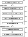
- FIG. 10 is a flowchart of the laser machining method according to the fourth embodiment.
- Step S41 is the same as step S21 in the laser machining method of the second embodiment.
- the processing position of the object to be processed 2 is irradiated with analytical light containing the first wavelength ( ⁇ 1) and the second wavelength ( ⁇ 2) (step S42). Specifically, the processing position of the processing object 2 is irradiated with analytical light including the first wavelength and the second wavelength emitted from the light source 32C.
- the signal light from the processing position of the processing object 2 is spectrally received (step S43). Specifically, the spectroscope 36 disperses the signal light which is the reflected light of the analysis light irradiated to the processing position of the object 2 to be processed, and the detector 33C receives the signal light dispersed by the spectroscope 36. ..
- the reflection spectrum showing the wavelength dependence of the intensity or reflectance of the signal light from the object 2 to be processed is calculated (step S44). Specifically, the reflection spectrum showing the wavelength dependence of the reflection intensity as shown in FIG. 11 is calculated by measuring the signal light separated by the spectroscope 36 and received by the detector 33C.
- the material is analyzed by collating the measured reflection spectrum of the signal light with the database 37 (step S45). Specifically, by collating the reflection spectrum measured by the detector 33C with the data group of a plurality of types of reflection spectra for each material stored in the database 37 as shown in FIG. 12, the object to be processed Determines which of the materials stored in database 37 the material at the coordinates at the processing position of 2 is closest. For example, when the reflection spectrum measured by the detector 33C is the reflection spectrum shown in FIG. 11, the reflection spectrum shown in FIG. 11 is the closest to the copper reflection spectrum among the plurality of reflection spectra shown in FIG. Therefore (because it is almost the same in FIGS.
- the material in the coordinates at the processing position of the object to be processed 2 is copper. That is, by collating the measured reflection spectrum of the signal light with the database, it is analyzed that the material at the processing position of the processing object 2 is likely to be copper.
- the machining conditions at the coordinates at the machining position of the machining object 2 are adjusted according to the material determined in step S45 (step S46). For example, as described above, when it is determined that the material at the processing position of the object 2 to be processed is copper, a laser beam having a wavelength suitable for copper (in the present embodiment, a second laser that is a blue laser beam). Processing conditions for laser processing with light L2) are created.
- the intensity of the laser beam is changed from the adjusted processing conditions (step S47). Specifically, the intensity of the first laser beam L1 emitted from the first laser oscillator 11 and the intensity of the second laser beam L2 emitted from the second laser oscillator 12 according to the processing conditions adjusted in step S46. To change.
- the object to be processed 2 is irradiated with a laser beam (step S48).
- the first laser beam L1 is emitted from the first laser oscillator 11 according to the respective intensities of the first laser beam L1 and the second laser beam L2 set in step S47 to be processed.
- the processing position of the object 2 is irradiated with the first laser beam L1, or the second laser beam L2 is emitted from the second laser oscillator 12 to irradiate the processing position of the object 2 with the second laser beam L2. To do.
- the laser processing method according to this embodiment can be performed by the above procedure.
- the laser machining may be completed by repeating steps S42 to S48 only once, or steps S42 to S48 may be repeated a plurality of times in real time. Good.
- the analysis unit 30C acquires the signal light from the processing object 2 and processes based on the acquired signal light, as in the second embodiment.
- the machining conditions of the object 2 are adjusted, and the drive control unit 20 drives the first laser oscillator 11 and the second laser oscillator 12 according to the adjusted machining conditions, thereby driving the first laser beam L1 and the second laser beam L1 and the second.
- the intensity of at least one of the laser beams L2 is changed to irradiate the workpiece 2 with at least one of the first laser beam L1 and the second laser beam L2.
- the same effect as that of the second embodiment is obtained. That is, since the first laser beam L1 and the second laser beam L2 can be irradiated to the machining position of the machining object 2 under the machining conditions suitable for the material of the machining object 2, a high-throughput and high-quality laser can be applied. Processing can be realized.
- the analysis unit 30C measures the spectroscope 36 that disperses the signal light from the object 2 to be processed and the signal light dispersed by the spectroscope 36. It has a detector 33C that measures a reflection spectrum that indicates the wavelength dependence of the intensity or reflectance of the signal light, and the data processing unit 31C processes the object 2 to be processed based on the reflection spectrum measured by the detector 33C. Adjust the machining conditions in the coordinates at the position.
- the reflection spectrum which is the wavelength dependence of the reflection intensity or reflectance peculiar to the material
- the analysis accuracy of the material property or the chemical composition of the material at the coordinates of the processing position of the processing object 2 is improved.
- the adjustment accuracy of laser processing conditions according to the material is improved. Therefore, it is possible to realize a laser processing apparatus capable of performing laser processing with higher processing quality.
- the data processing unit 31C is connected to a database 37 in which data groups of a plurality of types of reflection spectra for each material are stored, and the data processing unit 31 processes.
- the reflection spectrum obtained by the signal light from the object 2 is collated with the data group of the reflection spectrum stored in the database 37, and the material at the coordinate at the processing position of the processing object 2 is the material stored in the database 37. Which of the two is closest to the data is determined, and the processing conditions at the coordinates at the processing position of the processing object 2 are adjusted according to the determined material.
- the signal light which is the reflected light of the analysis light applied to the object to be processed 2
- the spectroscope 36 to calculate the reflection spectrum of the material of the object to be processed 2
- the present invention is not limited to this. ..
- the light dispersed by the spectroscope may be applied to the processed object 2 as analysis light.
- the analysis unit 30C irradiates the processing position of the processing object with a spectroscope that disperses the analysis light emitted from the light source 32 and the dispersed analysis light, and the dispersed analysis light is the processing object 2.
- the database 37 is a storage device such as a memory, and the analysis unit 30C has, but is not limited to this.
- the database 37 may be arranged in a place other than the laser processing apparatus 1C.
- the database 37 may be installed in a cloud server or the like connected to the data processing unit 31C via a network such as the Internet. By installing the database 37 on the cloud server, it is possible to improve the accuracy of the collation result by introducing machine learning using artificial intelligence as the database 37 is expanded and expanded.
- FIG. 13 is a block diagram showing a configuration of the laser processing apparatus 1D according to the fifth embodiment.
- the laser processing apparatus 1D has the first laser oscillator 11 and the second laser, similarly to the laser processing apparatus 1A to 1C according to the above embodiments 2 to 4. It includes an oscillator 12, a drive control unit 20, and an analysis unit 30D.
- the laser light for laser processing was selected by receiving the signal light from the processing object 2 with the detector and analyzing it.
- the laser light for laser processing is selected by capturing the signal light from the processing object 2 with the image sensor 38.
- the laser processing device 1D in the present embodiment has a different configuration of the analysis unit 30D from the laser processing devices 1A to 1C in the above embodiments 2 to 4.
- the analysis unit 30D in the present embodiment includes a data processing unit 31D, an image sensor 38, and an image processing unit 39.
- the laser processing apparatus 1D in the present embodiment further has a light source 60.
- the light source 60 irradiates the objects to be processed 2A and 2B with analytical light.
- the analytical light emitted by the light source 60 is, for example, white light.
- two workpieces 2A each made of only one type of metal material are welded and joined, and each of them is welded and joined.
- two workpieces 2B made of only one kind of metal material are welded and joined.
- the material constituting the object to be processed 2A is, for example, aluminum
- the material constituting the object to be processed 2B is, for example, copper.
- the image sensor 38 is an example of a solid-state image sensor in which a plurality of pixels that receive light are arranged two-dimensionally.
- the image sensor 38 is a color image sensor.
- the image sensor 38 has at least a first pixel provided with a filter for transmitting near infrared rays as a first filter for transmitting the first wavelength ( ⁇ 1) and a second wavelength ( ⁇ 2).
- a second filter to transmit it has a second pixel provided with a filter that transmits at least a part of wavelengths in the visible light region.
- the image sensor 38 captures a two-dimensional image of the processing objects 2A and 2B by receiving signal light from the processing objects 2A and 2B, and outputs the two-dimensional image to the data processing unit 31D. Specifically, the image sensor 38 captures signal light, which is the reflected light reflected by the analysis light emitted from the light source 60 by the objects to be processed 2A and 2B.
- the two-dimensional image captured by the image sensor 38 is input to the data processing unit 31D via the image processing unit 39.
- the image processing unit 39 generates image data of a two-dimensional image as shown in FIG. 14 based on the signal light received by the image sensor 38, and outputs the image data to the data processing unit 31D.
- the data processing unit 31D adjusts the processing conditions of the processing objects 2A and 2B according to the brightness corresponding to the processing positions (welding region) of the processing objects 2A and 2B in the two-dimensional image.
- the data processing unit 31D has a pixel signal intensity of the first wavelength of the signal light and a second signal light of the signal light at the processing positions of the processing objects 2A and 2B in the two-dimensional image received by the image sensor 38.
- the processing conditions of the processing objects 2A and 2B are adjusted by comparing with the pixel signal intensity of the wavelength.
- the reflectances of the objects to be processed 2A and 2B are estimated from a two-dimensional image composed of spectroscopic pixels provided on the pixels with a spectroscopic filter that transmits light of a specific wavelength, and the objects to be processed are processed.
- the wavelength of the processing laser beam suitable for each coordinate is selected from the relationship between the coordinates at the processing position of the object 2 and the brightness.
- FIG. 15 is a flowchart of the laser machining method according to the fifth embodiment.
- Step S51 is the same as step S21 in the laser machining method of the second embodiment.
- processing positions of the objects to be processed 2A and 2B are irradiated with analytical light (step S52). Specifically, the analysis light emitted from the light source 60 is applied to the region including the processing positions of the processing objects 2A and 2B.
- the image sensor 38 captures the signal light from the processing positions of the processing objects 2A and 2B (step S53). Specifically, the image sensor 38 captures the signal light, which is the reflected light reflected by the analysis light of the light source 60 irradiated to the processing positions of the processing objects 2A and 2B, and obtains a two-dimensional image. get. That is, a two-dimensional image including a plurality of spectral pixels is acquired for the objects to be processed 2A and 2B.
- the captured two-dimensional image is analyzed (step S54). Specifically, in the two-dimensional image captured by the image sensor 38, the pixel signal intensity (spectral pixel intensity) of the first wavelength of the signal light and the second wavelength of the signal light at the processing positions of the processing objects 2A and 2B. Compare with the pixel signal strength (spectral pixel strength) of.
- step S55 the machining conditions at the coordinates of the machining objects 2A and 2B at the machining positions are adjusted according to the comparison result in step S54 (step S55).
- Steps S54 and S55 can be performed, for example, as follows.
- the image sensor 38 receives signal light from the objects to be processed 2A and 2B, and each pixel is obtained from the intensity information from the adjacent spectral pixels.
- the color and brightness (luminance) of the light are determined, and a two-dimensional image is taken.
- the spectral pixel intensity can be acquired in the pixels corresponding to the respective coordinates of the processing positions of the processing objects 2A and 2B.
- the Bayer array pixel shown in FIG. 16 is known as one of the spectral pixels of a general color image sensor.
- one spectral pixel is composed of four sub-pixels, two green sub-pixels (G), one red sub-pixel (R), and one blue sub-pixel (B).
- a color filter such as a pigment is provided on each sub-pixel, and each sub-pixel has a specific spectral sensitivity.
- the brightness and color of one spectral pixel are determined by the four sub-pixels of the Bayer array pixels and output as one data.
- spectroscopic pixels of the Bayer array there are blue sub-pixels that have sensitivity to blue and red sub-pixels that have sensitivity to red, and it is possible to compose an image for each color scheme and acquire the reflection intensity corresponding to each coordinate. ..
- the processing condition is that laser processing (infrared processing) is performed with the first laser beam L1.
- the processing condition is that laser processing (blue processing) is performed with the second laser beam L2.
- the green sub-pixels indicate brightness information
- a monochrome two-dimensional image is formed by the signal intensity of the green sub-pixels, and which position on the two-dimensional image is suitable for laser processing of the first laser beam L1. It is also possible to display which position is suitable for laser processing of the second laser beam L2. It is also possible to reproduce the color by combining the output of the red sub-pixel and the output of the blue sub-pixel and display it as a normal color image.
- each spectral pixel of the image sensor 38 is not limited to the Bayer arrangement shown in FIG.
- it may be a white pixel in which one or two color filters of the green sub-pixel are not arranged. With this configuration, since the pixels are white, a monochrome luminance image can be captured with high sensitivity for all materials.
- each spectroscopic pixel of the image sensor 38 is a Bayer array pixel, and at least one or more near infrared (NIR: Near Infrared) sub-pixels are provided in each spectroscopic pixel. It may be. Also in this case, it is possible to compose an image for each color scheme and acquire the reflection intensity corresponding to each coordinate.
- NIR Near Infrared
- the processing condition is that laser processing (infrared processing) is performed with the first laser beam L1.
- the intensity of the laser beam is changed from the adjusted processing conditions (step S56). Specifically, the intensity of the first laser beam L1 emitted from the first laser oscillator 11 and the intensity of the second laser beam L2 emitted from the second laser oscillator 12 according to the processing conditions adjusted in step S55. To change.
- the objects to be processed 2A and 2B are irradiated with laser light (step S57).
- the first laser beam L1 is emitted from the first laser oscillator 11 according to the respective intensities of the first laser beam L1 and the second laser beam L2 set in step S56 to be processed.
- the first laser beam L1 is irradiated to the processing positions of the objects 2A and 2B, or the second laser beam L2 is emitted from the second laser oscillator 12, and the second laser is emitted to the processing positions of the objects 2A and 2B to be processed. It irradiates light L2.
- the laser processing method according to this embodiment can be performed by the above procedure.
- the laser machining may be completed by repeating steps S52 to S57 only once, or steps S52 to S57 may be repeated a plurality of times in real time. Good.
- the analysis unit 30D acquires the signal light from the processing objects 2A and 2B and is based on the acquired signal light, as in the second embodiment.
- the machining conditions of the objects to be machined 2A and 2B are adjusted, and the drive control unit 20 drives the first laser oscillator 11 and the second laser oscillator 12 according to the adjusted machining conditions to obtain the first laser beam.
- the processing object 2 is irradiated with at least one of the first laser beam L1 and the second laser beam L2 by changing the intensity of at least one of the L1 and the second laser beam L2.
- the first laser beam L1 and the second laser beam L2 can be irradiated to the machining positions of the machining objects 2A and 2B under the machining conditions suitable for the materials of the machining objects 2A and 2B, which is high. High-quality laser machining can be achieved with throughput.
- the analysis unit 30D transmits the two-dimensional images of the processing objects 2A and 2B to the data processing unit 31D by receiving the signal light from the processing objects 2A and 2B. It has an image sensor 38 to output, and the data processing unit 31D adjusts the processing conditions of the objects to be processed 2A and 2B according to the brightness corresponding to the processing position of the two-dimensional image captured by the image sensor 38.
- the image sensor 38 has a first pixel equipped with a first filter that transmits at least a third wavelength ( ⁇ 3) and a fourth wavelength ( ⁇ 4). It is preferable to have a second pixel equipped with a second filter for transmitting.
- the data processing unit 31D has the pixel signal intensity of the third wavelength of the signal light and the fourth wavelength of the signal light at the processing positions of the objects to be processed 2A and 2B in the two-dimensional image received by the image sensor 38. It is preferable to adjust the processing conditions of the object to be processed by comparing with the pixel signal strength of.
- the first filter may be a filter that transmits near infrared rays
- the second filter may be a filter that transmits at least a part of the wavelengths in the visible light region.
- the reflection spectrum in one Bayer array can be synthesized by comparing the signal intensities of each spectral pixel of the two-dimensional image captured by the image sensor 38.
- a reflection spectrum as illustrated in FIG. 18 can be obtained for each spectroscopic pixel.
- the data processing unit 31D is connected to a database in which the reflection spectrum data group is stored, and the reflection spectrum acquired by each spectral pixel of the two-dimensional image captured by the image sensor 38 is collated with the database to perform each spectrum. It is possible to analyze the material at the coordinate position of the pixel.
- the data processing unit 31D determines the pixel signal intensity of the third wavelength ( ⁇ 3) of the signal light at the processing positions of the processing objects 2A and 2B and the signal light of the signal light, as in the fourth embodiment.
- the pixel signal intensity of the fourth wavelength ( ⁇ 4) was collated with the reflection spectrum data group stored in the database, respectively, and the materials at the coordinates of the processing objects 2A and 2B at the processing positions were stored in the database. It may be determined which of the materials is closest to the material, and the processing conditions in the coordinates at the processing positions of the objects to be processed 2A and 2B may be adjusted according to the determined material.
- the third wavelength ( ⁇ 3) and the fourth wavelength ( ⁇ 4) are the second laser beam L1 emitted from the first laser oscillator 11 and the second laser beam L1 emitted from the second laser oscillator 12, respectively. It is desirable that the wavelength of the laser beam L2 is the same as that of the laser beam L2. With this configuration, the reflectance or reflection intensity of the workpiece 2 at the wavelength of the laser light emitted from these laser oscillators can be directly compared. Therefore, since the adjustment accuracy of the laser processing conditions is further improved, it is possible to realize a laser processing apparatus capable of performing laser processing with higher processing quality.
- the present embodiment as described above, the case where two workpieces 2A or 2B made of only one type of metal material are welded and joined has been described, but the present invention is not limited to this.
- the present embodiment can also be applied to the case where two composite materials 2X are welded together as in the above-described first to fourth embodiments.
- FIG. 19 is a block diagram showing a configuration of the laser processing apparatus 1E according to the sixth embodiment.
- the laser processing apparatus 1E includes the first laser oscillator 11 and the second laser oscillator 12 as in the case of the laser processing apparatus 1D according to the fifth embodiment. It includes a drive control unit 20 and an analysis unit 30E.
- the laser processing apparatus 1E captures and analyzes the signal light from the processing object 2 with the image sensor 38, similarly to the laser processing apparatus 1D according to the fifth embodiment.
- the analysis unit 30E includes a data processing unit 31E, an image sensor 38, and an image processing unit 39.
- the difference between the laser machining apparatus 1E according to the present embodiment and the laser machining apparatus 1D according to the fifth embodiment is that in the fifth embodiment, the light source 60 is used to irradiate the objects to be processed 2A and 2B with analytical light. However, in the present embodiment, the workpieces 2A and 2B to be processed are not irradiated with the analytical light.
- the plume (laser plume) generated during laser processing is analyzed as signal light. Therefore, in the present embodiment, the signal light from the processing objects 2A and 2B is accompanied by the irradiation of at least one of the first laser light L1 and the second laser light L2 on the processing objects 2A and 2B. This is the light emitted during processing.
- the plume is a metal element plasma that blows up at a high temperature during laser processing, and the color of the plume differs depending on the material like a flame reaction.
- the image sensor 38 acquires the emission spectrum of the plume by capturing the plume generated during laser processing in real time.
- the data processing unit 31E acquires the image sensor 38 and adjusts the processing conditions with respect to the coordinates of the processing positions of the processing objects 2A and 2B from the emission spectrum of the plume. By measuring the plume in this way, it is possible to select the optimum wavelength of the laser beam for processing and control the output, so that the processing quality of the processing objects 2A and 2B can be improved.
- one processing object 2A made of the first material (material A) and one processing object 2B made of the second material (material B) are used.
- the case of welding and joining is illustrated.
- FIG. 20 is a flowchart of the laser machining method according to the sixth embodiment.
- Step S61 is the same as step S21 in the laser machining method of the second embodiment.
- the object to be processed 2A or 2B is irradiated with a laser beam (step S62). Specifically, since the object to be processed 2A is arranged on the object to be processed 2B, the first laser beam L1 and the second laser beam as the laser beam for processing are located at the processing position of the object to be processed 2A. Irradiate at least one.
- the plume generated by laser irradiation is imaged by the image sensor 38 (step S63). Specifically, the plume generated by irradiating the processing positions of the processing objects 2A and 2B with at least one of the first laser light L1 and the second laser light as the processing laser light is generated from the processing object 2A or 2B. This signal light is imaged by the image sensor 38 as the signal light of the above, and the emission spectrum of the plume is acquired.
- the image sensor 38 detects the specific wavelength included in the plume as shown in FIG. It is possible to obtain the processing depth (or processing time) dependence of the light emission intensity.
- the captured plume image is analyzed (step S64). Specifically, the emission spectrum of the plume imaged by the image sensor 38 is collated with a database (not shown) in which data groups of a plurality of types of emission spectra for each material are stored, and the object to be processed during laser processing is collated. Determine which of the materials in the database is closest to stored in the database.
- step S65 the processing conditions of the object to be processed are adjusted according to the analysis result of step S64 (step S65). Specifically, the laser light having the wavelength suitable for the material determined in step S64 is selected from the first laser light L1 and the second laser light L2.
- the intensity of the laser beam is changed from the adjusted processing conditions (step S66). Specifically, the intensity of the first laser beam L1 emitted from the first laser oscillator 11 and the intensity of the second laser beam L2 emitted from the second laser oscillator 12 according to the processing conditions adjusted in step S65. To change.
- the object to be processed is irradiated with laser light (step S67).
- the first laser beam L1 is emitted from the first laser oscillator 11 according to the respective intensities of the first laser beam L1 and the second laser beam L2 set in step S66 to be processed.
- the processing position of the object 2 is irradiated with the first laser beam L1, or the second laser beam L2 is emitted from the second laser oscillator 12 to irradiate the processing position of the object 2 with the second laser beam L2. To do.
- the laser processing method according to this embodiment can be performed by the above procedure.
- the analysis unit 30E acquires the signal light from the processing objects 2A and 2B and is based on the acquired signal light, as in the case of the fifth embodiment.
- the machining conditions of the objects to be machined 2A and 2B are adjusted, and the drive control unit 20 drives the first laser oscillator 11 and the second laser oscillator 12 according to the adjusted machining conditions to obtain the first laser beam.
- the processing object 2 is irradiated with at least one of the first laser beam L1 and the second laser beam L2 by changing the intensity of at least one of the L1 and the second laser beam L2.
- the same effect as that of the fifth embodiment is obtained. That is, the first laser beam L1 and the second laser beam L2 can be irradiated to the machining positions of the machining objects 2A and 2B under the machining conditions suitable for the materials of the machining objects 2A and 2B, which is high. High-quality laser machining can be achieved with throughput.
- At least one of the first laser light L1 and the second laser light L2 is sent to the processing target 2A or 2B as the signal light from the processing target 2A and 2B. It is a light emission generated during processing due to irradiation.
- the material of the processing target 2A or 2B being laser-processed can be specified by the plume generated when the processing objects 2A and 2B are laser-processed, so that the optimum processing laser light for the material can be specified.
- the emission spectrum of the plume is acquired by using the image sensor 38, but the present invention is not limited to this.
- a spectroscope may be used instead of the image sensor 38.
- the analysis unit 30E has a spectroscope that disperses the plume (emission) and a data processing unit that outputs the emission spectrum of the plume, and the data processing unit has a processing position of the object to be processed from the emission spectrum of the plume.
- the processing conditions may be adjusted with respect to the coordinates of.
- the emission spectrum peculiar to the material can be acquired even with this configuration, the analysis accuracy of the material characteristics or the chemical composition of the material at the coordinates of the processing position of the object to be processed is improved, and the adjustment accuracy of the laser processing conditions according to the material can be improved. improves. As a result, it is possible to realize a laser processing apparatus capable of performing laser processing with high processing quality.
- the first laser beam L1 emitted from the first laser oscillator 11 and the second laser beam L2 emitted from the second laser oscillator 12 are the half mirror 51 and the lens 52.
- the object to be processed is irradiated with the same optical axis by the optical system 50, which is a single condensing optical system composed of the above, but the present invention is not limited to this.
- the optical system 50F which is an individual focusing optical system with the lens group 52a and the second lens group 52b.
- the light source 32 is a first light source that emits light including a first wavelength ( ⁇ 1) which is a peak wavelength of the first laser light L1 and a peak of the second laser light L2. It was composed of a second light source that emits light including a second wavelength ( ⁇ 2), which is a wavelength, but is not limited to this.
- the light source 32 includes a first light source that emits light having a third wavelength ( ⁇ 3) different from the first wavelength ( ⁇ 1) and the second wavelength ( ⁇ 2), and a first wavelength ( ⁇ 1). It may be composed of a second light source that emits light containing a second wavelength ( ⁇ 2) and a fourth wavelength ( ⁇ 4) different from the third wavelength ( ⁇ 3).
- the first light source of the light source 32 emits light having a peak wavelength of the third wavelength ( ⁇ 3) as the first analysis light, and the second light source of the light source 32 peaks as the second analysis light. It emits light whose wavelength is the fourth wavelength ( ⁇ 4).
- the third wavelength ( ⁇ 3) and the fourth wavelength ( ⁇ 4) are in the range from ultraviolet rays to near infrared rays. This is because the absorption / reflection spectra of metals and other materials often change from the ultraviolet region to the near infrared region.
- one of the third wavelength ( ⁇ 3) and the fourth wavelength ( ⁇ 4) is a wavelength of visible light or less and the other is a wavelength of near infrared rays or more. This is because if the third wavelength ( ⁇ 3) and the fourth wavelength ( ⁇ 4) are close to each other, it becomes difficult to identify the material.
- two laser oscillators a first laser oscillator 11 and a second laser oscillator 12 are used as the processing laser oscillator, but the present invention is not limited to this.
- three or more processing laser oscillators may be used. That is, wavelength selection and output control may be performed for three or more laser beams.
- the present invention is not limited to this.
- the present disclosure can be applied to the case of laser processing a metal and a resin, and can also be applied to the case of laser processing a resin and a resin.
- it can be applied not only to metals and resins but also to laser processing of various materials.
- the present disclosure is suitable for laser processing of dissimilar materials having different light absorption rates.
- the technique of the present disclosure is useful in a laser processing apparatus or the like that processes an object to be processed by irradiating it with a laser beam.
Landscapes
- Physics & Mathematics (AREA)
- Optics & Photonics (AREA)
- Engineering & Computer Science (AREA)
- Mechanical Engineering (AREA)
- Plasma & Fusion (AREA)
- Spectroscopy & Molecular Physics (AREA)
- Chemical & Material Sciences (AREA)
- General Health & Medical Sciences (AREA)
- General Physics & Mathematics (AREA)
- Immunology (AREA)
- Pathology (AREA)
- Biochemistry (AREA)
- Analytical Chemistry (AREA)
- Life Sciences & Earth Sciences (AREA)
- Health & Medical Sciences (AREA)
- Laser Beam Processing (AREA)
Priority Applications (2)
| Application Number | Priority Date | Filing Date | Title |
|---|---|---|---|
| JP2021556090A JP7695886B2 (ja) | 2019-11-13 | 2020-11-09 | レーザ加工装置 |
| US17/740,737 US20220266379A1 (en) | 2019-11-13 | 2022-05-10 | Laser processing device |
Applications Claiming Priority (2)
| Application Number | Priority Date | Filing Date | Title |
|---|---|---|---|
| JP2019-205117 | 2019-11-13 | ||
| JP2019205117 | 2019-11-13 |
Related Child Applications (1)
| Application Number | Title | Priority Date | Filing Date |
|---|---|---|---|
| US17/740,737 Continuation US20220266379A1 (en) | 2019-11-13 | 2022-05-10 | Laser processing device |
Publications (1)
| Publication Number | Publication Date |
|---|---|
| WO2021095699A1 true WO2021095699A1 (ja) | 2021-05-20 |
Family
ID=75912956
Family Applications (1)
| Application Number | Title | Priority Date | Filing Date |
|---|---|---|---|
| PCT/JP2020/041786 Ceased WO2021095699A1 (ja) | 2019-11-13 | 2020-11-09 | レーザ加工装置 |
Country Status (3)
| Country | Link |
|---|---|
| US (1) | US20220266379A1 (https=) |
| JP (1) | JP7695886B2 (https=) |
| WO (1) | WO2021095699A1 (https=) |
Cited By (3)
| Publication number | Priority date | Publication date | Assignee | Title |
|---|---|---|---|---|
| JP2024002820A (ja) * | 2022-06-24 | 2024-01-11 | 株式会社タマリ工業 | レーザ溶接装置 |
| WO2024105852A1 (ja) * | 2022-11-17 | 2024-05-23 | 株式会社ニコン | 加工システム |
| JP2025538069A (ja) * | 2022-12-20 | 2025-11-26 | アディジェ ソシエタ ペル アチオニ | 材料または加工パラメータの自動決定に基づく金属材料のレーザ加工方法 |
Families Citing this family (4)
| Publication number | Priority date | Publication date | Assignee | Title |
|---|---|---|---|---|
| US20230127791A1 (en) * | 2021-10-22 | 2023-04-27 | Embry-Riddle Aeronautical University, Inc. | Laser machining and related control for additive manufacturing |
| US20230377313A1 (en) * | 2022-05-18 | 2023-11-23 | Hitachi, Ltd. | State detection apparatus |
| DE102023135197A1 (de) * | 2023-12-14 | 2025-06-18 | TRUMPF Laser SE | DWM in SSL zur Parallelisierung |
| WO2026027464A1 (en) * | 2024-07-31 | 2026-02-05 | Atop S.P.A. | Laser welding station and method for welding together elements of metal manufactured products |
Citations (1)
| Publication number | Priority date | Publication date | Assignee | Title |
|---|---|---|---|---|
| JP2004058140A (ja) * | 2002-07-31 | 2004-02-26 | Matsushita Electric Ind Co Ltd | レーザスポット溶接方法及びレーザスポット溶接装置 |
Family Cites Families (13)
| Publication number | Priority date | Publication date | Assignee | Title |
|---|---|---|---|---|
| US5272309A (en) * | 1990-08-01 | 1993-12-21 | Microelectronics And Computer Technology Corporation | Bonding metal members with multiple laser beams |
| US6940592B2 (en) * | 2001-10-09 | 2005-09-06 | Applied Materials, Inc. | Calibration as well as measurement on the same workpiece during fabrication |
| WO2005029016A2 (en) * | 2003-03-13 | 2005-03-31 | University Of Florida | Material identification employing a grating spectrometer |
| ATE338604T1 (de) * | 2004-07-08 | 2006-09-15 | Trumpf Laser Gmbh & Co Kg | Laserschweissverfahren und -vorrichtung |
| ES3061078T3 (en) * | 2010-09-25 | 2026-03-31 | Ipg Photonics Canada Inc | Aparatus and method for coherent imaging and feedback control for modification of materials |
| JP5252026B2 (ja) * | 2011-05-10 | 2013-07-31 | パナソニック株式会社 | レーザ溶接装置及びレーザ溶接方法 |
| EP2567773B1 (de) * | 2011-09-08 | 2017-04-19 | TRUMPF Werkzeugmaschinen GmbH + Co. KG | Verfahren zum überprüfen der nahtqualität während eines laserschweissprozesses |
| US9956646B2 (en) * | 2014-02-28 | 2018-05-01 | Ipg Photonics Corporation | Multiple-beam laser processing using multiple laser beams with distinct wavelengths and/or pulse durations |
| DE102014212682A1 (de) * | 2014-07-01 | 2016-01-07 | Trumpf Werkzeugmaschinen Gmbh + Co. Kg | Verfahren und Vorrichtung zum Bestimmen einer Werkstoffart und/oder einer Oberflächenbeschaffenheit eines Werkstücks |
| JP6373714B2 (ja) * | 2014-10-14 | 2018-08-15 | 株式会社アマダホールディングス | ダイレクトダイオードレーザ加工装置及びその出力監視方法 |
| JP6294378B2 (ja) * | 2016-03-30 | 2018-03-14 | ファナック株式会社 | 前加工制御部を備えるレーザ加工装置及びレーザ加工方法 |
| JP7076951B2 (ja) * | 2017-05-23 | 2022-05-30 | 株式会社ディスコ | 反射率検出装置 |
| JP6717790B2 (ja) * | 2017-09-14 | 2020-07-08 | ファナック株式会社 | レーザ加工中に光学系の汚染レベルに応じて焦点シフトを調整するレーザ加工装置 |
-
2020
- 2020-11-09 JP JP2021556090A patent/JP7695886B2/ja active Active
- 2020-11-09 WO PCT/JP2020/041786 patent/WO2021095699A1/ja not_active Ceased
-
2022
- 2022-05-10 US US17/740,737 patent/US20220266379A1/en active Pending
Patent Citations (1)
| Publication number | Priority date | Publication date | Assignee | Title |
|---|---|---|---|---|
| JP2004058140A (ja) * | 2002-07-31 | 2004-02-26 | Matsushita Electric Ind Co Ltd | レーザスポット溶接方法及びレーザスポット溶接装置 |
Cited By (3)
| Publication number | Priority date | Publication date | Assignee | Title |
|---|---|---|---|---|
| JP2024002820A (ja) * | 2022-06-24 | 2024-01-11 | 株式会社タマリ工業 | レーザ溶接装置 |
| WO2024105852A1 (ja) * | 2022-11-17 | 2024-05-23 | 株式会社ニコン | 加工システム |
| JP2025538069A (ja) * | 2022-12-20 | 2025-11-26 | アディジェ ソシエタ ペル アチオニ | 材料または加工パラメータの自動決定に基づく金属材料のレーザ加工方法 |
Also Published As
| Publication number | Publication date |
|---|---|
| US20220266379A1 (en) | 2022-08-25 |
| JPWO2021095699A1 (https=) | 2021-05-20 |
| JP7695886B2 (ja) | 2025-06-19 |
Similar Documents
| Publication | Publication Date | Title |
|---|---|---|
| JP7695886B2 (ja) | レーザ加工装置 | |
| US7315039B2 (en) | Confocal microspectroscope | |
| JP5354335B2 (ja) | レーザ加工良否判定方法及び装置 | |
| JP6373714B2 (ja) | ダイレクトダイオードレーザ加工装置及びその出力監視方法 | |
| US10094656B2 (en) | Chromatic confocal sensor and measurement method | |
| CN1250935C (zh) | 检测和校正多激光光束不对准的系统和方法 | |
| JP6775430B2 (ja) | 照明装置及び照明装置を監視するための方法 | |
| US20220297228A1 (en) | Alignment unit, sensor module comprising same, and laser working system comprising the sensor module | |
| KR102843336B1 (ko) | 검사 장치 및 검사 방법 | |
| US20220331911A1 (en) | Method for comparing laser processing systems and method for monitoring a laser processing process and associated laser processing system | |
| EP1202102B1 (en) | Laser microscope | |
| US20080062512A1 (en) | Confocal electroluminescence spectral microscope | |
| CN120970530A (zh) | 基于面光源的光谱共聚焦三维形貌测量方法和系统 | |
| WO2022209930A1 (ja) | レーザ加工ヘッド及びこれを備えたレーザ加工システム | |
| JP2022158669A (ja) | レーザ加工ヘッド及びレーザ加工システム並びにレーザ加工システムの異常判定方法 | |
| WO2010007852A1 (ja) | レーザ加工装置及びその加工方法 | |
| KR102534005B1 (ko) | 형광분석모듈 및 그를 가지는 형광분석시스템 | |
| JP2008256440A (ja) | 分析装置 | |
| CN119968544A (zh) | 三维形状检查装置及三维形状检查方法 | |
| JP2007007698A (ja) | レーザ加工ヘッド | |
| JP2006047270A (ja) | 波長可変単色光源 | |
| JP2005070021A (ja) | 検査用光源装置 | |
| TW201620657A (zh) | 可根據光束靈敏度聚焦的自動聚焦系統與方法 | |
| JP2020146727A (ja) | レーザ加工装置 | |
| US20180117710A1 (en) | Laser system and laser flare machining method |
Legal Events
| Date | Code | Title | Description |
|---|---|---|---|
| 121 | Ep: the epo has been informed by wipo that ep was designated in this application |
Ref document number: 20886254 Country of ref document: EP Kind code of ref document: A1 |
|
| ENP | Entry into the national phase |
Ref document number: 2021556090 Country of ref document: JP Kind code of ref document: A |
|
| NENP | Non-entry into the national phase |
Ref country code: DE |
|
| 122 | Ep: pct application non-entry in european phase |
Ref document number: 20886254 Country of ref document: EP Kind code of ref document: A1 |