WO2021095637A1 - 超音波モータ - Google Patents
超音波モータ Download PDFInfo
- Publication number
- WO2021095637A1 WO2021095637A1 PCT/JP2020/041365 JP2020041365W WO2021095637A1 WO 2021095637 A1 WO2021095637 A1 WO 2021095637A1 JP 2020041365 W JP2020041365 W JP 2020041365W WO 2021095637 A1 WO2021095637 A1 WO 2021095637A1
- Authority
- WO
- WIPO (PCT)
- Prior art keywords
- piezoelectric element
- wiring
- vibrating body
- main surface
- piezoelectric
- Prior art date
- Legal status (The legal status is an assumption and is not a legal conclusion. Google has not performed a legal analysis and makes no representation as to the accuracy of the status listed.)
- Ceased
Links
Images







Classifications
-
- H—ELECTRICITY
- H02—GENERATION; CONVERSION OR DISTRIBUTION OF ELECTRIC POWER
- H02N—ELECTRIC MACHINES NOT OTHERWISE PROVIDED FOR
- H02N2/00—Electric machines in general using piezoelectric effect, electrostriction or magnetostriction
- H02N2/10—Electric machines in general using piezoelectric effect, electrostriction or magnetostriction producing rotary motion, e.g. rotary motors
- H02N2/103—Electric machines in general using piezoelectric effect, electrostriction or magnetostriction producing rotary motion, e.g. rotary motors by pressing one or more vibrators against the rotor
-
- H—ELECTRICITY
- H02—GENERATION; CONVERSION OR DISTRIBUTION OF ELECTRIC POWER
- H02N—ELECTRIC MACHINES NOT OTHERWISE PROVIDED FOR
- H02N2/00—Electric machines in general using piezoelectric effect, electrostriction or magnetostriction
- H02N2/0005—Electric machines in general using piezoelectric effect, electrostriction or magnetostriction producing non-specific motion; Details common to machines covered by H02N2/02 - H02N2/16
- H02N2/001—Driving devices, e.g. vibrators
-
- H—ELECTRICITY
- H02—GENERATION; CONVERSION OR DISTRIBUTION OF ELECTRIC POWER
- H02N—ELECTRIC MACHINES NOT OTHERWISE PROVIDED FOR
- H02N2/00—Electric machines in general using piezoelectric effect, electrostriction or magnetostriction
- H02N2/10—Electric machines in general using piezoelectric effect, electrostriction or magnetostriction producing rotary motion, e.g. rotary motors
- H02N2/12—Constructional details
Definitions
- the present invention relates to an ultrasonic motor having a plurality of piezoelectric elements.
- An object of the present invention is to provide an ultrasonic motor capable of increasing the vibration efficiency of a vibrating body and increasing the rotational efficiency.
- the ultrasonic motor according to the present invention includes a plate-shaped vibrating body including a first main surface and a second main surface facing each other, and a plurality of plate-shaped vibrating bodies provided on the first main surface of the vibrating body.
- a stator having a piezoelectric element, a rotor in direct or indirect contact with the second main surface of the vibrating body, and insulation provided on the first main surface of the vibrating body.
- a wiring member including a base material and a first wiring and a second wiring provided on the insulating base material, and the first main surface and the second main surface of the vibrating body.
- the plurality of piezoelectric elements When the direction along the center of rotation is the axial direction, the plurality of piezoelectric elements vibrate the vibrating body to generate a traveling wave that orbits around the axial direction.
- the plurality of piezoelectric elements are dispersed and arranged along the circumferential direction of the traveling wave, and the plurality of piezoelectric elements include a first piezoelectric element, a second piezoelectric element, a third piezoelectric element, and a fourth piezoelectric element.
- the first piezoelectric element and the third piezoelectric element face each other with the center of the traveling wave interposed therebetween, and the second piezoelectric element and the fourth piezoelectric element are opposed to each other.
- the first wiring of the wiring member is electrically connected to the first piezoelectric element and the third piezoelectric element.
- the wiring is electrically connected to the second piezoelectric element and the fourth piezoelectric element, and when viewed from the axial direction, the second wiring is said from the second piezoelectric element side. It passes over the third piezoelectric element and extends toward the fourth piezoelectric element side.
- the vibration efficiency of the vibrating body can be increased, and the rotation efficiency can be increased.
- FIG. 1 is a perspective view of an ultrasonic motor according to a first embodiment of the present invention.
- FIG. 2 is an exploded perspective view of the ultrasonic motor according to the first embodiment of the present invention.
- FIG. 3 is a bottom view of the stator according to the first embodiment of the present invention.
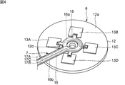
- FIG. 4 is a perspective view of the stator and the wiring member according to the first embodiment of the present invention.
- FIG. 5 is a perspective view showing the stator and the wiring member according to the first embodiment of the present invention, in which the insulating cover is omitted.
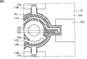
- FIG. 6 is a plan view showing the vicinity of the portion where the third piezoelectric element and the first wiring in the first embodiment of the present invention are connected, omitting the insulating cover.
- FIG. 1 is a perspective view of an ultrasonic motor according to a first embodiment of the present invention.
- FIG. 2 is an exploded perspective view of the ultrasonic motor according to the first embodiment of the present invention.
- FIG. 3 is
- FIG. 7 is a perspective view showing the vicinity of a portion to which the third piezoelectric element and the first wiring in the first embodiment of the present invention are connected, omitting the insulating cover.
- FIG. 8 is a plan view showing the vicinity of a portion to which the third piezoelectric element and the first wiring in the first embodiment of the present invention are connected.
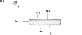
- FIG. 9 is a front sectional view of the third piezoelectric element according to the first embodiment of the present invention.
- FIG. 10 is a circuit diagram for explaining a circuit for applying a drive signal to the piezoelectric element in the first embodiment of the present invention.
- 11 (a) to 11 (c) are schematic bottom views of a stator for explaining an excited traveling wave in the first embodiment of the present invention.
- FIG. 12 is a plan view showing the vicinity of the third piezoelectric element in the first modification of the first embodiment, omitting the insulating cover.
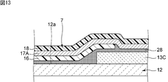
- FIG. 13 is a schematic cross-sectional view showing the vicinity of the third piezoelectric element in the second modification of the first embodiment.
- FIG. 1 is a perspective view of an ultrasonic motor according to the first embodiment of the present invention.
- FIG. 2 is an exploded perspective view of the ultrasonic motor according to the first embodiment.
- the ultrasonic motor 1 has a first case member 2A and a second case member 2B.
- the second case member 2B is fixed on the first case member 2A.
- the case 2 is configured.
- a bearing 3, a rotor 4, a friction material 5, a stator 6, and a pressurizing spring 8 are arranged inside the case 2.
- the stator 6 has a vibrating body 12. In the ultrasonic motor 1, the vibrating body 12 of the stator 6 is vibrated to generate a traveling wave that orbits around the axial direction Z shown in FIG. The rotor 4 is rotated by this traveling wave.
- the vibrating body 12 of the stator 6 has a first main surface 12a and a second main surface 12b.
- the first main surface 12a and the second main surface 12b face each other.
- the axial direction Z is a direction connecting the first main surface 12a and the second main surface 12b, and means a direction along the center of rotation.
- FIG. 3 is a bottom view of the stator according to the first embodiment.
- the stator 6 has a plurality of piezoelectric elements.
- the plurality of piezoelectric elements are the first piezoelectric element 13A, the second piezoelectric element 13B, the third piezoelectric element 13C, and the fourth piezoelectric element 13D.
- the plurality of piezoelectric elements are provided on the first main surface 12a of the vibrating body 12. More specifically, the plurality of piezoelectric elements are attached to the vibrating body 12 with an adhesive.
- an adhesive for example, an epoxy resin or a polyethylene resin can be used as the adhesive.
- the plurality of piezoelectric elements are dispersedly arranged along the circumferential direction of the traveling wave so as to generate a traveling wave that orbits around the axial direction Z.
- the first piezoelectric element 13A and the third piezoelectric element 13C face each other with the center of the traveling wave in between.
- the second piezoelectric element 13B and the fourth piezoelectric element 13D face each other with the center of the traveling wave interposed therebetween.
- the center of the traveling wave coincides with the center of the stator 6 and the center of the vibrating body 12.
- the center of the traveling wave does not necessarily have to coincide with the center of the stator 6 and the center of the vibrating body 12.
- the third piezoelectric element 13C has a rectangular shape, and the first side 13a and the second side which are the outer peripheral edges of the third piezoelectric element 13C. It has 13b, a third side 13c and a fourth side 13d.
- the first side 13a and the third side 13c face each other.
- the second side 13b and the fourth side 13d face each other.
- the outside and the inside are referred to as the outside when viewed from the axial direction Z, and the side close to the axis is referred to as the inside, unless otherwise specified.
- the first side 13a is located inside the third side 13c.
- the second side 13b and the fourth side 13d extend from the inside to the outside.
- the first piezoelectric element 13A, the second piezoelectric element 13B, and the fourth piezoelectric element 13D also have first to fourth sides like the third piezoelectric element 13C.
- a plurality of piezoelectric elements are electrically connected to a wiring member.
- the wiring member is electrically connected to the connector 9 shown in FIG.
- the plurality of piezoelectric elements are electrically connected to the outside via a wiring member and a connector 9.
- FIG. 4 is a perspective view of the stator and the wiring member in the first embodiment.
- FIG. 5 is a perspective view showing the stator and the wiring member according to the first embodiment, omitting the insulating cover. The insulating cover will be described later.
- the wiring member 7 has an insulating base material 16 provided on the first main surface 12a of the vibrating body 12.
- the insulating base material 16 has a first base material main surface 16a and a second base material main surface 16b.
- the first base material main surface 16a and the second base material main surface 16b face each other.
- the second base material main surface 16b is the surface on the vibrating body 12 side.
- a first wiring 17A and a second wiring 17B are provided on the first base material main surface 16a of the insulating base material 16.
- the insulating base material 16 is arranged between the first wiring 17A and the second wiring 17B and the vibrating body 12.
- the first wiring 17A and the second wiring 17B are electrically insulated from the vibrating body 12.
- the wiring member 7 has a ground wiring 17C.
- the ground wiring 17C has a portion provided on the first main surface 16a of the insulating base material 16 and a portion provided on the first main surface 12a of the vibrating body 12.
- the vibrating body 12 is made of metal.
- the ground wiring 17C is electrically connected to the vibrating body 12. More specifically, the ground wiring 17C is connected to the vibrating body 12 at a portion located inside the first wiring 17A.
- the ground wiring 17C is electrically connected to the ground potential via the vibrating body 12.
- the position of the ground wiring 17C is not limited to the above.
- the first wiring 17A, the second wiring 17B, and the ground wiring 17C are connected to the connector 9.
- the wiring member 7 has an insulating cover 18 that covers the first wiring 17A, the second wiring 17B, the ground wiring 17C, and the first base material main surface 16a of the insulating base material 16. ..
- the insulating cover 18 may cover the first wiring 17A and the second wiring 17B.
- the insulating cover 18 may reach on a plurality of piezoelectric elements or on a vibrating body 12.
- first wiring 17A, the second wiring 17B, and the ground wiring 17C for example, copper foil or the like can be used.
- the materials of the first wiring 17A, the second wiring 17B, and the ground wiring 17C are not limited to the above, and an appropriate metal can be used.
- the insulating base material 16 and the insulating cover 18 for example, polyimide can be used.
- the materials of the insulating base material 16 and the insulating cover 18 are not limited to the above, and appropriate insulating materials can be used.
- FIG. 6 is a plan view in which the insulating cover is omitted, showing the vicinity of the portion where the third piezoelectric element and the first wiring are connected in the first embodiment.
- FIG. 7 is a perspective view showing the vicinity of the portion where the third piezoelectric element and the first wiring in the first embodiment are connected, omitting the insulating cover.
- the insulating base material 16 is shown by hatching.
- the first wiring 17A of the wiring member 7 is electrically connected to the first piezoelectric element 13A and the third piezoelectric element 13C. More specifically, as shown in FIG. 5, the portion of the first wiring 17A connected to the first piezoelectric element 13A is not provided on the insulating base material 16 of the wiring member 7. Similarly, as shown in FIG. 6, the portion of the first wiring 17A connected to the third piezoelectric element 13C is not provided on the insulating base material 16 of the wiring member 7. More specifically, as shown in FIG. 7, the insulating substrate 16 has an opening 16c. When viewed from the axial direction Z, the opening 16c is located on the third piezoelectric element 13C. A portion of the first wiring 17A connected to the third piezoelectric element 13C is located in the opening 16c. On the other hand, the first wiring 17A is not electrically connected to the second piezoelectric element 13B and the fourth piezoelectric element 13D.
- the second wiring 17B is electrically connected to the second piezoelectric element 13B and the fourth piezoelectric element 13D. More specifically, the portion of the second wiring 17B connected to the second piezoelectric element 13B and the portion connected to the fourth piezoelectric element 13D are placed on the insulating base material 16 of the wiring member 7. Not provided. On the other hand, the second wiring 17B is not electrically connected to the first piezoelectric element 13A and the third piezoelectric element 13C.
- the second wiring 17B When viewed from the axial direction Z, the second wiring 17B extends from the second piezoelectric element 13B side to the third piezoelectric element 13C and toward the fourth piezoelectric element 13D side.
- An insulating base material 16 is arranged between the second wiring 17B and the third piezoelectric element 13C.
- the first wiring 17A is bonded to the first piezoelectric element 13A and the third piezoelectric element 13C with an adhesive.
- the second wiring 17B is bonded to the second piezoelectric element 13B and the fourth piezoelectric element 13D with an adhesive.
- an adhesive for example, an epoxy resin or a polyethylene resin can be used as the adhesive.
- the material of the adhesive is not limited to the above.
- the form of joining the first wiring 17A and the second wiring 17B and each piezoelectric element is not limited to the above, and may be joined by, for example, solder.
- the portion of the first wiring 17A connected to the first piezoelectric element 13A has a first comb-shaped portion 17a.
- the portion of the second wiring 17B connected to the second piezoelectric element 13B has a second comb-shaped portion 17b.
- the portion of the first wiring 17A connected to the third piezoelectric element 13C has a third comb-shaped portion 17c.
- the portion of the second wiring 17B connected to the fourth piezoelectric element 13D has a fourth comb-shaped portion 17d.
- the first comb-shaped portion 17a, the second comb-shaped portion 17b, and the fourth comb-shaped portion 17d are comb-shaped portions facing outward.
- the third comb-shaped portion 17c is a comb-shaped portion facing inward.
- the first comb-shaped portion 17a, the second comb-shaped portion 17b, the third comb-shaped portion 17c, and the fourth comb-shaped portion 17d face inward when viewed from the axial direction Z. It may be facing outwards.
- the first wiring 17A and the second wiring 17B do not necessarily have to have the above-mentioned comb-shaped portions.
- the feature of this embodiment is that the second wiring 17B passes from the second piezoelectric element 13B side to the third piezoelectric element 13C and goes to the fourth piezoelectric element 13D side when viewed from the axial direction Z. It is in the extension.
- the wiring can be routed by the wiring member 7 whose wiring is a single layer. Therefore, the vibration efficiency of the vibrating body 12 can be increased, and the rotational efficiency of the ultrasonic motor 1 can be increased. Further, since it is not necessary to make the wiring member 7 multi-layered, the productivity can be improved.
- the insulating base material 16 has an opening 16c, and when viewed from the axial direction Z, the opening 16c of the insulating base material 16 is the outer peripheral edge of the third piezoelectric element 13C. It is preferable to include a part of. More specifically, for example, as in the present embodiment, the opening 16c preferably includes a first side 13a as a part of the outer peripheral edge of the third piezoelectric element 13C. In this case, the area of the inner portion of the opening 16c when viewed from the axial direction Z can be effectively increased.
- the first wiring 17A preferably has a first comb-shaped portion 17a and a third comb-shaped portion 17c.
- the first piezoelectric element 13A and the third piezoelectric element 13C and the insulating cover 18 are formed. Can be easily joined.
- the second wiring 17B preferably has a second comb-shaped portion 17b and a fourth comb-shaped portion 17d.
- the third comb-shaped portion 17c of the first wiring 17A has a comb-shaped portion facing inward.
- the third comb-shaped portion 17c of the first wiring 17A preferably has a comb-shaped portion facing the outer peripheral edge of the third piezoelectric element 13C, that is, the first side 13a.
- the adhesive is directed inward as viewed from the axial direction Z. Easy to be discharged.
- the piezoelectricity of the adhesive is piezoelectric. It is possible to facilitate the discharge to the outside of the element surface. Therefore, the adhesive can be more easily discharged from between the first wiring 17A and the third piezoelectric element 13C outside the surface of the piezoelectric element without lengthening the routing of the second wiring 17B.
- FIG. 8 is a plan view showing the vicinity of the portion where the third piezoelectric element and the first wiring in the first embodiment are connected.
- the insulating cover 18 has a notch 18a. When viewed from the axial direction Z, the notch portion 18a is located inside the opening 16c. The cutout portion 18a surrounds a portion of the first wiring 17A connected to the third piezoelectric element 13C. The cutout portion 18a is located on the third piezoelectric element 13C between a portion of the insulating cover 18 covering the first wiring 17A and a portion covering the second wiring 17B. There is. As a result, even when there is a height difference between the surfaces of the first wiring 17A and the second wiring 17B on the insulating cover 18 side, both the first wiring 17A and the second wiring 17B and the insulating cover 18 are twisted. It can be reliably adhered. However, the insulating cover 18 does not have to have the notch portion 18a.
- the first wiring 17A passes through the portion where the insulating base material 16 reaches the third piezoelectric element 13C and reaches the third piezoelectric element 13C.
- the first wiring 17A and the third piezoelectric element 13C can be electrically connected while the first wiring 17A and the vibrating body 12 are more reliably electrically insulated.
- the first wiring 17A passes through the portion where the insulating base material 16 reaches the first piezoelectric element 13A and reaches the first piezoelectric element 13A. As shown in FIG.
- the second wiring 17B passes through the portion where the insulating base material 16 reaches the second piezoelectric element 13B and reaches the second piezoelectric element 13B. Further, it is preferable that the second wiring 17B passes through the portion where the insulating base material 16 reaches the fourth piezoelectric element 13D and reaches the fourth piezoelectric element 13D.
- the plurality of piezoelectric elements are four piezoelectric elements.
- the number of piezoelectric elements is not limited to this, and the plurality of piezoelectric elements may be 4x piezoelectric elements. Note that x is a positive number of 1 or more.
- the insulating base material 16 preferably has two or more openings 16c.
- a wiring pattern for driving is provided on the first base material main surface 16a of the insulating base material 16, and the detection pattern is provided on the second base material main surface 16b. It may be provided.
- the detection pattern is a wiring pattern that constitutes a circuit that detects the vibration of the piezoelectric element. In this way, the wiring member 7 may use a two-layer wiring pattern.
- the rotor 4 has a disc-shaped rotor main body 4a and a rotating shaft 4b having one end connected to the rotor main body 4a.
- the rotor 4 is rotated, and the rotating shaft 4b is rotated accordingly.
- the shape of the rotor body 4a is not limited to the above.
- the shape of the rotor body 4a viewed from the axial direction Z may be, for example, a regular polygon such as a regular hexagon, a regular octagon, or a regular decagon.
- the friction material 5 is fixed to the lower surface of the rotor body 4a of the rotor 4 and is provided to increase the frictional force between the rotor 4 and the vibrating body 12.
- the rotor 4 is indirectly in contact with the second main surface 12b of the vibrating body 12 via the friction material 5, but the friction material 5 does not necessarily have to be provided. In this case, the rotor 4 may be in direct contact with the second main surface 12b of the vibrating body 12.
- the first case member 2A is provided with a cross-shaped recess 2a on the upper surface.
- a pressurizing spring 8 as a pressurizing member is arranged between the first main surface 12a of the vibrating body 12 and the first case member 2A.
- the pressurizing spring 8 has a cross-shaped shape in a plan view, and the tip of the cross-shaped portion fits into the cross-shaped portion of the recess 2a.
- the pressurization spring 8 is configured so that the center of the shaft and the center of the spring are aligned with each other without rotating with respect to the center in the axial direction.
- the pressurization spring 8 applies pressurization to pressurize the vibrating body 12 to the rotor 4 side.
- the first case member 2A and the second case member 2B are fixed, and the pressurization is applied by the elastic force of the pressurization spring 8.
- an appropriate fixing structure such as a method using a bolt and a nut for inserting the through hole 2b and the through hole 2c can be used.
- the second case member 2B is provided with a cylindrical protrusion 2e having a through hole 2d in the center.
- the bearing 3 is housed in the through hole 2d, and the rotating shaft 4b is inserted into the through hole of the bearing 3.
- the vibrating body 12 of the stator 6 has a disk shape.
- the vibrating body 12 is provided with a through hole 12d at the center.
- the shape of the vibrating body 12 as viewed from the axial direction Z is not limited to a circle, and may be a regular polygon such as a regular hexagon, a regular octagon, or a regular decagon.
- the vibrating body 12 does not have to have the through hole 12d.
- the vibrating body 12 may have a plate shape.
- a plurality of protrusions 12c are provided on the second main surface 12b of the vibrating body 12.
- the plurality of protrusions 12c are portions of the vibrating body 12 that are in contact with the friction material 5.
- the plurality of protrusions 12c are in contact with the rotor body 4a of the rotor 4.
- Each protrusion 12c protrudes in the axial direction Z from the second main surface 12b of the vibrating body 12.
- the plurality of protrusions 12c are arranged in an annular shape.
- the plurality of protrusions 12c may not necessarily be provided.
- the vibrating body 12 is made of an appropriate metal.
- the vibrating body 12 does not necessarily have to be made of metal.
- the vibrating body 12 may be made of another elastic body such as ceramics, a silicon material or a synthetic resin.
- the vibrating body 12 is preferably made of metal. As a result, the vibrating body 12 can be electrically connected to the ground potential, so that the wiring can be simplified.
- FIG. 9 is a front sectional view of the third piezoelectric element in the first embodiment.
- the third piezoelectric element 13C has a piezoelectric body 14.
- the piezoelectric body 14 has a third main surface 14a and a fourth main surface 14b.
- the third main surface 14a and the fourth main surface 14b face each other.
- the third piezoelectric element 13C has a first electrode 15a and a second electrode 15b.
- the first electrode 15a is provided on the third main surface 14a of the piezoelectric body 14, and the second electrode 15b is provided on the fourth main surface 14b.
- the first piezoelectric element 13A, the second piezoelectric element 13B, and the fourth piezoelectric element 13D are also configured in the same manner as the third piezoelectric element 13C.
- the first and second signals are given to the first and third piezoelectric elements 13A and 13C and the piezoelectric elements of the second and fourth piezoelectric elements 13B and 13D, respectively.
- WO2010 / 061508A1 discloses a structure in which a plurality of piezoelectric elements are dispersedly arranged in the circumferential direction and driven to generate a traveling wave in the stator 6.
- a traveling wave in the stator 6.
- the structure for generating this traveling wave not only the following description but also the detailed description will be omitted by referring to the configuration described in WO2010 / 061508A1 in the present specification.
- FIGS. 11 (a) to 11 (c) are schematic bottom views for explaining the traveling wave in a more understandable manner.
- FIGS. 11 (a) to 11 (c) in the gray scale, the closer it is to black, the greater the stress in one direction, and the closer it is to white, the greater the stress in the other direction.
- FIG. 11A shows a three-wave standing wave X
- FIG. 11B shows a three-wave standing wave Y. It is assumed that the first to fourth piezoelectric elements 13A to 13D are arranged at a central angle of 30 °. Each piezoelectric element shall have a circumferential dimension that occupies a central angle of 60 °.
- a +, A ⁇ , B +, and B ⁇ in FIGS. 11 (a) to 11 (c) indicate the polarization directions of the piezoelectric body 14.
- + Means that the surface is polarized from the third main surface 14a to the fourth main surface 14b in the thickness direction.
- A indicates that it is the first piezoelectric element 13A and the third piezoelectric element 13C
- B indicates that it is the second piezoelectric element 13B and the fourth piezoelectric element 13D.
- the rotor 4 pressed against the second main surface 12b of the vibrating body 12 rotates around the center Z in the axial direction. ..
- the configuration for generating a traveling wave is not limited to the configuration shown in FIG. 11, and various conventionally known configurations for generating a traveling wave can be used.
- FIG. 12 is a plan view showing the vicinity of the third piezoelectric element in the first modification of the first embodiment, omitting the insulating cover.
- the routing of the first wiring 27A and the second wiring 27B near the third piezoelectric element 13C and the arrangement of the insulating base material 26 are different. More specifically, the insulating base material 26 covers the second side 13b and the fourth side 13d of the third piezoelectric element 13C. When viewed from the axial direction Z, the second wiring 27B overlaps the second side 13b and the fourth side 13d of the third piezoelectric element 13C. A part of the first wiring 27A extends substantially parallel to the first side 13a of the third piezoelectric element 13C.
- the wiring can be routed by the wiring member 27 having a single layer of wiring, as in the first embodiment. Therefore, the vibration efficiency of the vibrating body 12 can be increased, and the rotational efficiency of the ultrasonic motor can be increased. Further, the adhesive between the first wiring 27A and the third piezoelectric element 13C can be easily discharged, and it is unlikely that stress is concentrated on the lump of the adhesive due to a temperature change.
- the wiring member 7 is vertically formed in the portion where the wiring member 7 reaches the third piezoelectric element 13C from the first main surface 12a of the vibrating body 12. It's bent. Therefore, in this portion, the wiring member 7 extends in the normal direction of the first main surface 12a. Similarly, the wiring member 7 is bent vertically even in the portion where the wiring member 7 reaches each piezoelectric element other than the third piezoelectric element 13C from the first main surface 12a.
- the configuration of the portion where the wiring member 7 reaches each piezoelectric element is not limited to the above.
- FIG. 13 is a schematic cross-sectional view showing the vicinity of the third piezoelectric element in the second modification of the first embodiment.
- the wiring member 7 in the portion where the wiring member 7 reaches the third piezoelectric element 13C from the first main surface 12a of the vibrating body 12, the wiring member 7 is relative to the normal direction of the first main surface 12a. It extends at an angle. This is due to the configuration of the adhesive layer 28 in this modification. Specifically, the adhesive layer 28 is provided from the first main surface 12a of the vibrating body 12 to the third piezoelectric element 13C. In the portion where the adhesive layer 28 extends from the first main surface 12a to the third piezoelectric element 13C, the thickness of the adhesive layer 28 becomes thicker as it approaches the third piezoelectric element 13C. A wiring member 7 is provided on the adhesive layer 28. As a result, the wiring member 7 is inclined and extends along the shape of the adhesive layer 28. In this way, sudden bending of the wiring member 7 is suppressed. Therefore, the wiring member 7 is unlikely to be disconnected.
- the wiring member 7 is inclined with respect to the normal direction of the first main surface 12a. And may be extended. As a result, the wiring member 7 is more difficult to break.
- the adhesive layer 28 for example, an epoxy resin or a polyethylene resin can be used.
- the wiring can be routed by the wiring member 7 in which the wiring is a single layer, as in the first embodiment. Therefore, the vibration efficiency of the vibrating body 12 can be increased, and the rotational efficiency of the ultrasonic motor can be increased.
- First and second electrodes 16 Insulating base materials 16a, 16b ... 1st and 2nd base material main surfaces 16c ... Openings 17A, 17B ... 1st and 2nd wirings 17C ... Ground wirings 17a to 17d ... 1st to 4th comb-shaped portions 18 ... Insulation cover 18a ... Cutting Notch 26 ... Insulating base material 27 ... Wiring members 27A, 27B ... First and second wiring 28 ... Adhesive layer
Landscapes
- General Electrical Machinery Utilizing Piezoelectricity, Electrostriction Or Magnetostriction (AREA)
Priority Applications (3)
| Application Number | Priority Date | Filing Date | Title |
|---|---|---|---|
| CN202080077865.1A CN114651392B (zh) | 2019-11-15 | 2020-11-05 | 超声波马达 |
| JP2021556059A JP7310915B2 (ja) | 2019-11-15 | 2020-11-05 | 超音波モータ |
| US17/661,451 US11736040B2 (en) | 2019-11-15 | 2022-04-29 | Ultrasonic motor with improved rotation efficiency |
Applications Claiming Priority (2)
| Application Number | Priority Date | Filing Date | Title |
|---|---|---|---|
| JP2019206729 | 2019-11-15 | ||
| JP2019-206729 | 2019-11-15 |
Related Child Applications (1)
| Application Number | Title | Priority Date | Filing Date |
|---|---|---|---|
| US17/661,451 Continuation US11736040B2 (en) | 2019-11-15 | 2022-04-29 | Ultrasonic motor with improved rotation efficiency |
Publications (1)
| Publication Number | Publication Date |
|---|---|
| WO2021095637A1 true WO2021095637A1 (ja) | 2021-05-20 |
Family
ID=75911357
Family Applications (1)
| Application Number | Title | Priority Date | Filing Date |
|---|---|---|---|
| PCT/JP2020/041365 Ceased WO2021095637A1 (ja) | 2019-11-15 | 2020-11-05 | 超音波モータ |
Country Status (4)
| Country | Link |
|---|---|
| US (1) | US11736040B2 (https=) |
| JP (1) | JP7310915B2 (https=) |
| CN (1) | CN114651392B (https=) |
| WO (1) | WO2021095637A1 (https=) |
Citations (2)
| Publication number | Priority date | Publication date | Assignee | Title |
|---|---|---|---|---|
| JP2002142473A (ja) * | 2000-11-02 | 2002-05-17 | Canon Inc | 振動波駆動装置および振動波駆動装置を用いた装置 |
| JP2009131145A (ja) * | 2007-11-27 | 2009-06-11 | Korea Inst Of Science & Technology | 円環型圧電超音波共振器及びそれを用いた圧電超音波回転モータ |
Family Cites Families (5)
| Publication number | Priority date | Publication date | Assignee | Title |
|---|---|---|---|---|
| JPH0744850B2 (ja) | 1986-05-06 | 1995-05-15 | キヤノン株式会社 | 振動波モ−タ− |
| JPH07107756A (ja) * | 1993-09-30 | 1995-04-21 | Murata Mfg Co Ltd | 超音波モータ |
| JP2006352984A (ja) * | 2005-06-15 | 2006-12-28 | Tdk Corp | 圧電薄膜振動子およびその製造方法、並びにそれを用いた駆動装置および圧電モータ |
| EP3283790A4 (en) * | 2015-04-15 | 2018-12-05 | Genesis Robotics LLP | Wave actuator |
| JP6844868B2 (ja) | 2019-06-05 | 2021-03-17 | 株式会社トライフォース・マネジメント | 発電素子 |
-
2020
- 2020-11-05 WO PCT/JP2020/041365 patent/WO2021095637A1/ja not_active Ceased
- 2020-11-05 CN CN202080077865.1A patent/CN114651392B/zh active Active
- 2020-11-05 JP JP2021556059A patent/JP7310915B2/ja active Active
-
2022
- 2022-04-29 US US17/661,451 patent/US11736040B2/en active Active
Patent Citations (2)
| Publication number | Priority date | Publication date | Assignee | Title |
|---|---|---|---|---|
| JP2002142473A (ja) * | 2000-11-02 | 2002-05-17 | Canon Inc | 振動波駆動装置および振動波駆動装置を用いた装置 |
| JP2009131145A (ja) * | 2007-11-27 | 2009-06-11 | Korea Inst Of Science & Technology | 円環型圧電超音波共振器及びそれを用いた圧電超音波回転モータ |
Also Published As
| Publication number | Publication date |
|---|---|
| CN114651392B (zh) | 2026-03-24 |
| US11736040B2 (en) | 2023-08-22 |
| US20220263431A1 (en) | 2022-08-18 |
| JP7310915B2 (ja) | 2023-07-19 |
| JPWO2021095637A1 (https=) | 2021-05-20 |
| CN114651392A (zh) | 2022-06-21 |
Similar Documents
| Publication | Publication Date | Title |
|---|---|---|
| US10639676B2 (en) | Vibration device | |
| CN101310433B (zh) | 超声波马达 | |
| WO2021095637A1 (ja) | 超音波モータ | |
| JP7392874B2 (ja) | 超音波モータ | |
| JP6913642B2 (ja) | 振動発電デバイス | |
| JP7310914B2 (ja) | 超音波モータ | |
| JP4095282B2 (ja) | 振動波駆動装置 | |
| JPH0744850B2 (ja) | 振動波モ−タ− | |
| WO2022220061A1 (ja) | 超音波モータ | |
| WO2023157372A1 (ja) | 超音波モータ | |
| JPH05344759A (ja) | 超音波モータ | |
| JP5765044B2 (ja) | 光スキャナ | |
| JP2021197850A (ja) | 超音波モータ | |
| JPH01177878A (ja) | 振動波モータ | |
| JP2021141758A (ja) | 振動型駆動装置及びフレキシブル基板 | |
| WO2025197156A1 (ja) | ロータ、ステータ及び超音波モータ | |
| KR20030081278A (ko) | 란쥬반형 진동자를 이용한 초음파 회전 모터 | |
| WO2022224702A1 (ja) | 超音波モータ | |
| JPH0654557A (ja) | 超音波モータ | |
| JP4350208B2 (ja) | 振動波駆動装置 | |
| JPWO2021095637A5 (https=) | ||
| JP2005223968A (ja) | 振動子および振動波駆動装置 | |
| JPH11341847A (ja) | 超音波モータ | |
| CN118020245A (zh) | 超声波电机 | |
| JP2000350481A (ja) | 振動波駆動装置および事務機 |
Legal Events
| Date | Code | Title | Description |
|---|---|---|---|
| 121 | Ep: the epo has been informed by wipo that ep was designated in this application |
Ref document number: 20886892 Country of ref document: EP Kind code of ref document: A1 |
|
| ENP | Entry into the national phase |
Ref document number: 2021556059 Country of ref document: JP Kind code of ref document: A |
|
| NENP | Non-entry into the national phase |
Ref country code: DE |
|
| 122 | Ep: pct application non-entry in european phase |
Ref document number: 20886892 Country of ref document: EP Kind code of ref document: A1 |