WO2021095248A1 - 表示装置、制御システム、制御方法およびプログラム - Google Patents
表示装置、制御システム、制御方法およびプログラム Download PDFInfo
- Publication number
- WO2021095248A1 WO2021095248A1 PCT/JP2019/044924 JP2019044924W WO2021095248A1 WO 2021095248 A1 WO2021095248 A1 WO 2021095248A1 JP 2019044924 W JP2019044924 W JP 2019044924W WO 2021095248 A1 WO2021095248 A1 WO 2021095248A1
- Authority
- WO
- WIPO (PCT)
- Prior art keywords
- unit
- display
- information
- display mode
- temperature
- Prior art date
- Legal status (The legal status is an assumption and is not a legal conclusion. Google has not performed a legal analysis and makes no representation as to the accuracy of the status listed.)
- Ceased
Links
Images















Classifications
-
- F—MECHANICAL ENGINEERING; LIGHTING; HEATING; WEAPONS; BLASTING
- F24—HEATING; RANGES; VENTILATING
- F24F—AIR-CONDITIONING; AIR-HUMIDIFICATION; VENTILATION; USE OF AIR CURRENTS FOR SCREENING
- F24F11/00—Control or safety arrangements
- F24F11/50—Control or safety arrangements characterised by user interfaces or communication
- F24F11/52—Indication arrangements, e.g. displays
- F24F11/523—Indication arrangements, e.g. displays for displaying temperature data
-
- F—MECHANICAL ENGINEERING; LIGHTING; HEATING; WEAPONS; BLASTING
- F24—HEATING; RANGES; VENTILATING
- F24F—AIR-CONDITIONING; AIR-HUMIDIFICATION; VENTILATION; USE OF AIR CURRENTS FOR SCREENING
- F24F2110/00—Control inputs relating to air properties
- F24F2110/10—Temperature
-
- F—MECHANICAL ENGINEERING; LIGHTING; HEATING; WEAPONS; BLASTING
- F24—HEATING; RANGES; VENTILATING
- F24F—AIR-CONDITIONING; AIR-HUMIDIFICATION; VENTILATION; USE OF AIR CURRENTS FOR SCREENING
- F24F2120/00—Control inputs relating to users or occupants
- F24F2120/10—Occupancy
- F24F2120/12—Position of occupants
Definitions
- the present invention relates to a display device, a control system, a control method and a program.
- the spatial temperature distribution of the target space is measured by a thermal image sensor, and the person in the target space is identified from the spatial temperature distribution information obtained by the measurement.
- An air-conditioning controller that controls the operation of an air-conditioning facility that air-conditions the target space based on the temperature difference of the above has been proposed (see, for example, Patent Document 1).
- the present invention has been made in view of the above reasons, and an object of the present invention is to provide a display device, a control system, a control method, and a program that enable a user to quickly grasp the environment of a living space in which he / she spends. To do.
- the display device is An environment detection unit that detects the first environmental parameter of each area when the living space is divided into multiple areas, With at least one display
- a display mode specifying unit that specifies the display mode of at least one display unit based on the first environmental information indicating the first environmental parameters of each of the plurality of regions detected by the environment detection unit.
- a display control unit that controls the at least one display unit so as to have the display mode is provided.
- the environment detection unit detects the first environmental parameter of each of the plurality of areas when the living space is divided into a plurality of areas, and the display mode specifying unit is detected by the environment detection unit.
- the display mode of at least one display unit is specified based on the first environmental information indicating the first environmental parameter of each area.
- the display control unit controls at least one display unit so as to have the above-mentioned display mode.
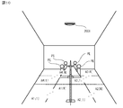
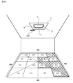
- FIG. 1 The figure which shows the use example of the display device which concerns on Embodiment 1 of this invention.
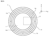
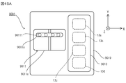
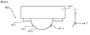
- Top view of the display device according to the first embodiment Side view of the display device according to the first embodiment
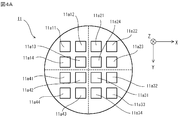
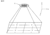
- Schematic plan view of the sensor according to the first embodiment Schematic diagram of operation of the sensor according to the first embodiment
- Schematic diagram of operation of the average temperature calculation unit according to the first embodiment An operation explanatory view of the display device according to the first embodiment.
- An operation explanatory view of the display device according to the second embodiment. The figure which shows an example of the area information stored in the area storage part which concerns on Embodiment 2.
- An operation explanatory view of the display device according to the second embodiment. A flowchart showing an example of a flow of display control processing executed by the display device according to the second embodiment.
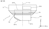
- Top view of the display device according to the third embodiment Side view of the display device according to the third embodiment
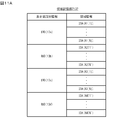
- An operation explanatory view of the display device according to the third embodiment. The figure which shows an example of the area information which the area storage part which concerns on Embodiment 3 store.
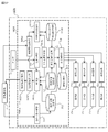
- Schematic configuration diagram of the control system according to the fourth embodiment A block diagram showing a hardware configuration of a display device according to a fourth embodiment.
- Schematic configuration diagram of the control system according to the seventh embodiment A block diagram showing a functional configuration of a display device according to a seventh embodiment.
- Schematic configuration diagram of the control system according to the eighth embodiment A block diagram showing a functional configuration of the display device according to the eighth embodiment.
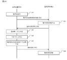
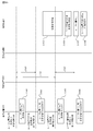
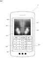
- a sequence diagram showing the operation of the control system according to the eighth embodiment The figure which shows an example of the operation screen image displayed on the terminal apparatus which concerns on Embodiment 8.
- a sequence diagram showing the operation of the control system according to the eighth embodiment The figure which shows an example of the operation screen image displayed on the terminal apparatus which concerns on Embodiment 8.
- Block diagram showing the functional configuration of the display device according to the modified example A flowchart showing an example of the flow of display control processing executed by the display device according to the modified example.
- Block diagram showing the functional configuration of the display device according to the modified example A flowchart showing an example of the flow of device control processing executed by the display device according to the modified example.
- Block diagram showing the functional configuration of the display device according to the modified example A flowchart showing an example of the flow of device control processing executed by the display device according to the modified example.
- Sequence diagram showing the operation of the control system according to the modified example Sequence diagram showing the operation of the control system according to the modified example
- the display system according to the present embodiment is detected by an environment detection unit that detects the first environmental parameters of each of the plurality of areas when the living space is divided into a plurality of areas, at least one display unit, and an environment detection unit.
- a display mode specifying unit that specifies a display mode of at least one display unit and at least one display unit are set to the display mode based on the first environmental information indicating the first environmental parameters of each of the plurality of regions. It is provided with a display control unit for controlling the above.
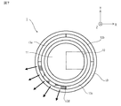
- the display device 1 is installed together with the air conditioner 2 on the ceiling of a room in a building such as a building or a factory.
- the installation position of the display device 1 is not limited to the ceiling, and may be installed on the wall or floor of the room, for example.
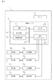
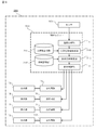
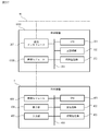
- the display device 1 includes a sensor 11, four display units 13a, 13b, 13c, 13d, a control unit 10 that controls the display units 13a, 13b, 13c, and 13d, and a sensor. 11.
- a box-shaped housing 19 having a circular shape in a plan view for accommodating the display units 13a, 13b, 13c, 13d and the control unit 10 is provided. Further, as shown in FIG.
- the display device 1 includes lighting circuits 12a, 12b, 12c, 12d for separately lighting the display units 13a, 13b, 13c, and 13d.
- the display units 13a, 13b, 13c, and 13d have, for example, at least one light emitting device (not shown) arranged at equal intervals in the circumferential direction of the housing 19 of the display device 1.
- the light emitting device has a light emitting element such as an LED (Light Emitting Diode) and an organic EL element. Further, the light emitting device has three types of light emitting elements that emit red light, blue light, and green light, respectively.
- the lighting circuits 12a, 12b, 12c, and 12d each include, for example, a power conversion circuit and a drive unit that drives the power conversion circuit, and supply a direct current to the light emitting devices of the display units 13a, 13b, 13c, and 13d, respectively. By doing so, the light emitting device is turned on.
- the lighting circuits 12a, 12b, 12c, and 12d each turn on the light emitting device by supplying a direct current to the light emitting device when the lighting command information for instructing the light emitting device to be turned on is input from the control unit 10.
- the extinguishing command information for instructing the control unit 10 to turn off the light emitting device while the light emitting devices of the display units 13a, 13b, 13c, and 13d are lit, respectively.
- the light emitting device is turned off by cutting off the supply of the direct current to the light emitting device.
- the lighting circuits 12a, 12b, 12c, and 12d have red light, yellow light, and yellow light by adjusting the ratio of the light emission intensities of the three types of light emitting elements of the light emitting devices of the display units 13a, 13b, 13c, and 13d, respectively. It emits one of four types of light, green light and blue light.
- the lighting circuits 12a, 12b, 12c, and 12d are not limited to one, and for example, one for each of a plurality of light emitting devices arranged at equal intervals in the circumferential direction of the housing of the display device 1. It may be provided one by one. Further, the lighting circuits 12a, 12b, 12c, and 12d may be a group of lighting circuits for lighting the light emitting devices belonging to each of the four groups when the plurality of light emitting devices are divided into four groups in the circumferential direction.
- the sensor 11 is an environment detection unit that detects the temperature, which is the first environmental parameter of each of the four regions A1, A2, A3, and A4 when the living space is divided into the four regions A1, A2, A3, and A4.
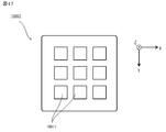
- the sensor 11 has 16 thermopile 11a11, 11a12, 11a13, 11a14, 11a21, 11a22, 11a23, 11a24, 11a31, 11a32, 11a33, 11a34, 11a41, 11a42, 11a43, 11a44, as shown in FIG. 4A, for example.
- the 16 thermopile 11a11, 11a12, 11a13, ... 11a44 are two-dimensionally arranged in a matrisk pattern of 4 rows and 4 columns.
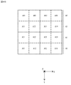
- thermopile 11a11, 11a12, 11a13, ... 11a44 each output a voltage signal according to the detected temperature. Then, as shown in FIG. 4B, the thermopile 11a11, 11a12, 11a13, 11a14 detects the temperature of the area A1 of the room in which the display device 1 is installed, and the thermopile 11a21, 11a22, 11a23, 11a24 has the display device 1 The temperature of the area A2 of the installed room is detected.
- thermopile 11a31, 11a32, 11a33, 11a34 detects the temperature of the area A3 of the room where the display device 1 is installed, and the thermopile 11a41, 11a42, 11a43, 11a44 is the area A4 of the room where the display device 1 is installed. Detects the temperature of.
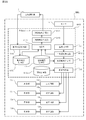
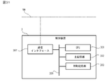
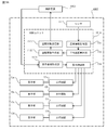
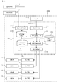
- the control unit 10 includes an MPU (Micro Processing Unit) 101, a main storage unit 102, an auxiliary storage unit 103, a sensor interface 104, a display interface 105, and a bus 109 that connects them to each other.
- the main storage unit 102 is a volatile memory such as a RAM (Random Access Memory), and is used as a work area of the MPU 101.
- the auxiliary storage unit 103 is a non-volatile memory such as a semiconductor flash memory, and stores a program for the MPU 101 to execute various processes.
- the sensor interface 104 is connected to the sensor 11 via a signal line, and when a detection signal output from the sensor 11 is input, the sensor interface 104 is converted into temperature information reflecting the temperature detected by the sensor 11 and output to the MPU 101.
- the display interface 105 is connected to each of the lighting circuits 12a, 12b, 12c, and 12d via a signal line, and when the lighting command information or the turning off command information is input from the MPU 101, the lighting command information or the turning off command information is input. Based on this, a control signal is generated and output to the lighting circuits 12a, 12b, 12c, and 12d.
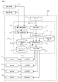
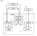
- the temperature acquisition unit 111, the average temperature calculation unit 112, the display mode specifying unit 113, and the display control It functions as a unit 114.
- the auxiliary storage unit 103 shown in FIG. 3 is a reference for the temperature of the regions A1, A2, A3, and A4 in the living space, which is a condition for lighting the display units 13a, 13b, 13c, and 13d. It has a temperature range storage unit 131 for storing temperature range information indicating a temperature range, and a region storage unit 132. As shown in FIG.
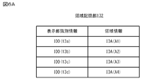
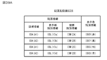
- the area storage unit 132 displays the area information for identifying the areas A1, A2, A3, and A4 in the living space on the side of the display device 1 in the direction facing the areas A1, A2, A3, and A4.
- the display unit identification information for identifying the display units 13a, 13b, 13c, and 13d provided in the above is stored in association with the display unit identification information.
- the area information is, for example, when the display device 1 is installed on the ceiling of the room, the installer sets the positions of the areas A1, A2, A3, A4 and the display device 1 in the living space where the display device 1 is installed. It is stored in the area storage unit 132 in association with the display unit identification information based on the relationship.
- the temperature acquisition unit 111 acquires the temperature information input from the sensor 11 via the sensor interface 104. Specifically, the temperature acquisition unit 111 acquires the temperature information by converting the voltage information corresponding to the voltage signal input from the thermopile 11a11, 11a12, 11a13, ... 11a44 of the sensor 11 into the temperature.
- the average temperature calculation unit 112 calculates the average temperature of the temperature in at least one sub-region included in each of the regions A1, A2, A3, and A4. For example, as shown in FIG.
- the average temperature calculation unit 112 calculates the average value of the temperatures of the sub-regions A11, A12, A13, and A14 as the temperature of the sub-region A1, and calculates the average value of the temperatures of the sub-regions A21, A22, A23, and A24. Calculated as the temperature of region A2. Further, the average temperature calculation unit 112 calculates the average value of the temperatures of the sub-regions A31, A32, A33, and A34 as the temperature of the sub-region A3, and calculates the average value of the temperatures of the sub-regions A41, A42, A43, and A44 as the region. Calculated as the temperature of A4.
- the display mode specifying unit 113 refers to the reference temperature range information stored in the temperature range storage unit 131, and sets the temperature of each of the four regions A1, A2, A3, and A4 detected by the sensor 11. Based on the temperature information which is the first environmental information shown, the display modes of the four display units 13a, 13b, 13c, and 13d are specified. It is assumed that the display mode specifying unit 113 determines that the temperature of the region A4 is within the reference temperature range among the temperatures of the four regions A1, A2, A3, and A4 calculated by the average temperature calculating unit 112, for example.
- the display mode specifying unit 113 refers to the display unit identification information corresponding to the area information of the area A4 stored in the area storage unit 132, turns on the display unit 13d, and turns off the display units 13a, 13b, and 13c. Specify the display mode to be maintained in. Then, the display mode specifying unit 113 outputs the specified display mode information to the display control unit 114.
- the display mode information includes display unit identification information of each of the display units 13a, 13b, 13c, and 13d, and information indicating lighting or extinguishing associated with the display unit identification information. Further, the display mode information includes display color information indicating display colors corresponding to the temperatures of the regions A1, A2, A3, and A4.
- This display color information is set so that, for example, the higher the temperature of the regions A1, A2, A3, and A4, the more reddish the color, and the lower the temperature of the regions A1, A2, A3, and A4, the more bluish the color. ..
- the display control unit 114 controls the four display units 13a, 13b, 13c, 13d so that the four display units 13a, 13b, 13c, and 13d have the display mode notified from the display mode specifying unit 113.
- the display control unit 114 has four lighting circuits 12a, 12b, 12c, 12d so that the four display units 13a, 13b, 13c, and 13d have a display mode notified by the display mode specifying unit 113.
- the lighting command information includes ratio information indicating the ratio of the emission intensities of the above-mentioned three types of light emitting elements corresponding to the display color indicated by the above-mentioned display color information.
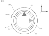
- the display control unit 114 When, for example, the display control unit 114 inputs information indicating a display mode in which the display unit 13d is turned on from the display mode specifying unit 113 and the display units 13a, 13b, and 13c are maintained in the extinguished state, the display control unit 114 outputs the lighting command information to the lighting circuit 12d. By outputting to, the display unit 13d is turned on in the display color indicated by the display color information as shown in FIG.
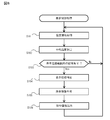
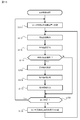
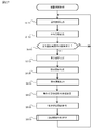
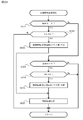
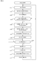
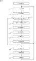
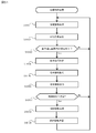
- the display control process executed by the display device 1 according to the present embodiment will be described with reference to FIG.
- This display control process is started, for example, when the power is turned on to the display device 1.
- the temperature acquisition unit 111 acquires the temperature information of each of the sub-regions A11, A12, A13, ..., A44 detected by the sensor 11 (step S101).
- the average temperature calculation unit 112 calculates the average temperature of the sub-regions A11, A12, A13, ..., A44 included in each of the regions A1, A2, A3, and A4 (step S102).
- the average temperature calculation unit 112 calculates the average temperature of the four sub-regions included in each of the regions A1, A2, A3, and A4 as the temperature of each of the regions A1, A2, A3, and A4. Subsequently, the display mode specifying unit 113 determines whether or not the temperatures of the regions A1, A2, A3, and A4 are within the reference temperature range (step S103). When the display mode specifying unit 113 determines that all the temperatures of the regions A1, A2, A3, and A4 are outside the reference temperature range (step S103: No), the process of step S101 is executed again.
- the display mode specifying unit 113 determines that the temperature of at least one of the regions A1, A2, A3, and A4 is within the reference temperature range (step S103: Yes).
- the display mode specifying unit 113 refers to the information stored in the area storage unit 132 to light the display unit (for example, the display unit 13d) corresponding to the area where the temperature is within the reference temperature range, and other areas.
- the display mode in which the display units (for example, display units 13a, 13b, 13c) corresponding to the above are maintained in the extinguished state is specified (step S104).
- the display mode specifying unit 113 outputs the display mode information including the display unit identification information of the display unit to be turned on and the display unit identification information of the display unit that maintains the extinguished state to the display control unit 114.
- the display control unit 114 After that, the display control unit 114 generates command information including lighting command information or extinguishing command information for each of the display units 13a, 13b, 13c, and 13d based on the display mode information input from the display mode specifying unit 113. (Step S105). Next, the display control unit 114 outputs the generated command information to each of the lighting circuits 12a, 12b, 12c, and 12d (step S106). Subsequently, the process of step S101 is executed again.
- the display device 1 As described above, according to the display device 1 according to the present embodiment, the four regions A1, A2, A3, when the sensor 11 divides the living space into the four regions A1, A2, A3, and A4, The temperature of each A4 is detected. Further, the display mode specifying unit 113 displays the four display units 13a, 13b, 13c, and 13d based on the temperature information indicating the temperatures of the four regions A1, A2, A3, and A4 detected by the sensor 11. To identify. Then, the display control unit 114 controls the four display units 13a, 13b, 13c, and 13d so as to have the above-mentioned display mode.
- the user can recognize the temperatures of the four regions A1, A2, A3, and A4 of the living space only by confirming the display modes of the four display units 13a, 13b, 13c, and 13d. It is possible for the user to quickly grasp the temperature distribution of the living space in which he / she spends.
- the display device is different from the first embodiment in that it includes a human presence area detection unit that detects an area in which a person exists based on the first environmental information of each of the plurality of areas.
- the display mode specifying unit specifies the display mode based on the position of the area detected by the human presence area detection unit.
- the display device 2001 includes a sensor 2011, four display units 13a, 13b, 13c, 13d, and a control unit 2010 that controls the display units 13a, 13b, 13c, 13d. And.
- the same reference numerals as those in FIG. 5 are attached to the same configurations as those in the first embodiment.
- the sensor 2011 has a higher resolution than the sensor 11 described in the first embodiment.
- the living space has 4 N (N is an integer of 5 or more) regions A1 [1], ...
- A1 [N], A2 [1], ..., A2 [N], A3 [1], ..., A3 [N], A4 [1], ..., A4 [N] Multiple regions of time A1 [1], ..., A1 [N], A2 [1], ..., A2 [N], A3 [1], ..., A3 [N], A4 [1] ], ..., A4 [N] can detect the respective temperatures.
- the hardware configuration of the control unit 2010 is the same as the hardware configuration of the control unit 10 according to the first embodiment, and includes an MPU, a main storage unit, an auxiliary storage unit, a sensor interface, a display interface, and a bus.
- the auxiliary storage unit stores a program for the MPU to execute various processes.
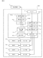
- the MPU functions as a temperature acquisition unit 111, a person presence area detection unit 2115, a display mode specifying unit 2113, and a display control unit 114 by reading a program stored in the auxiliary storage unit into the main storage unit and executing the program.
- the auxiliary storage unit includes a human information storage unit 2131 for storing temperature range information indicating a temperature range on the surface of a person and human dimension information regarding a person's shape, size, and the like, and an area storage unit 2132.
- the area storage unit 2132 displays area information for identifying the areas A1 [1], ..., A4 [N] in the living space, and displays the area information 13a, 13b, 13c of the display device 2001. , 13d is stored in association with the display unit identification information.
- the area information includes, for example, when the display device 2001 is installed on the ceiling of the room, the installer sets each area A1 [1], ..., A4 [N] in the living space where the display device 2001 is installed. Based on the positional relationship with the display device 2001, the area storage unit 2132 stores the information in association with the display unit identification information.
- the human presence area detection unit 2115 is the area where a person exists based on the temperature information indicating the temperature of each of the areas A1 [1], ..., A4 [N] detected by the sensor 11. Is detected. Specifically, the person existence area detection unit 2115 is a person from the areas A1 [1], ..., A4 [N] based on the temperature range information and the person dimension information stored in the person information storage unit 2131. Detects the area where is present. Further, the human presence area detection unit 2115 outputs the area information of the area in which the person exists to the display mode specifying unit 2113.
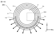
- the display mode specifying unit 2113 refers to the area information stored in the area storage unit 2132, and based on the area information input from the human presence area detection unit 2115, displays the display modes of the display units 13a, 13b, 13c, and 13d. Identify. For example, as shown in FIG. 10, a person exists in the areas A3 [1], ..., A4 [N] in the room, and the person existence area detection unit 2115 sets the area A3 [1], ... , It is assumed that a person existing in A4 [N] is detected.
- the display mode specifying unit 2113 refers to the display unit identification information corresponding to the area information of the areas A3 [1], ..., A4 [N] stored in the area storage unit 2132, and refers to the display unit 13c, A display mode is specified in which the 13d is turned on and the display units 13a and 13b are maintained in the off state. Then, the display mode specifying unit 2113 outputs information indicating the specified display mode to the display control unit 114. At this time, the display control unit 114 lights the display units 13c and 13d as shown in FIG. 11B by outputting the lighting command information to the lighting circuits 12c and 12d.
- this display control process is started when, for example, the power is turned on to the display device 2001.
- the temperature acquisition unit 111 acquires temperature information for each of the regions A1 [1], ..., A4 [N] detected by the sensor 11 (step S2101).
- the human presence region detection unit 2115 is based on the temperature information indicating the temperatures of the regions A1 [1], ..., A4 [N] detected by the sensor 11, and the regions A1 [1], ... -The existence or nonexistence of a person in any area of A4 [N] is determined (step S2102).
- the human presence area detection unit 2115 determines whether or not the area in which a person exists has been detected (step S2103).
- the person existence area detection unit 2115 determines that the area in which a person exists is not detected (step S2103: No)
- the process of step S2101 is executed again.
- the human presence area detection unit 2115 has determined that the area where a person exists has been detected (step S2103: Yes).
- the display mode specifying unit 2113 turns on the display unit (for example, display units 13c and 13d) corresponding to the area where a person exists, and turns off the display unit (for example, display units 13a and 13b) corresponding to the other areas.
- the display mode to be maintained in the state is specified (step S2104).
- the display mode specifying unit 113 refers to the information stored in the area storage unit 2132 to identify the display unit identification information of the display unit associated with the area in which a person exists and the display unit identification of other display units. Get information and. Then, the display mode specifying unit 113 outputs information indicating the display mode including the acquired display unit identification information and the information indicating lighting or extinguishing associated with the acquired display unit identification information to the display control unit 114.
- the display control unit 114 provides command information including lighting command information or extinguishing command information for each of the display units 13a, 13b, 13c, and 13d based on the information indicating the display mode input from the display mode specifying unit 2113. Generate (step S2105). Next, the display control unit 114 outputs the generated command information to each of the lighting circuits 12a, 12b, 12c, and 12d (step S2106). Subsequently, the process of step S101 is executed again.
- the human presence area detection unit 2115 is based on the temperature information of each of the areas A1 [1], ..., A4 [N], and is a person. Detects the area where is present. Then, the display mode specifying unit 2113 specifies the display mode based on the position of the area detected by the human presence area detection unit 2115. As a result, the user can recognize the area where the person exists in the living space only by confirming the display modes of the four display units 13a, 13b, 13c, and 13d, and the user can recognize the area where the person exists. There is an advantage that it becomes easy to set the temperature of the living space in consideration of the position.
- the display device is different from the first embodiment in that the environment detection unit detects the first environmental parameters of each of the plurality of regions in order for each region of a preset unit detection number. To do.
- the display device 3001 includes a sensor unit 3011, four display units 13a, 13b, 13c, 13d, display units 13a, 13b, 13c, 13d, and a sensor.
- a control unit 3010 for controlling the unit 3011 and a housing 19 are provided.
- FIG. 13A and FIG. 13B the same reference numerals as those in FIGS. 2A and 2B are attached to the same configurations as those in the first embodiment.
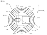
- the sensor unit 3011 includes a sensor 3011a, a sensor support base 3011c that is cylindrical and supports the sensor 3011a, and a drive unit 3011b that drives the sensor support base 3011c.
- the sensor 3011a has two thermopile 30111 arranged side by side in the radial direction of the sensor support base 3011c.
- the sensor support base 3011c is rotatably attached to the housing 19 around the central axis J3. Then, the drive unit 3011b changes the direction of the sensor 3011a by rotating the sensor support base 3011c around the central axis J3.
- the hardware configuration of the control unit 3010 according to the present embodiment is the same as the hardware configuration of the control unit 10 according to the first embodiment, and is the MPU, the main storage unit, the auxiliary storage unit, the sensor interface, the display interface, and the bus. And.
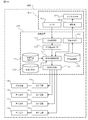
- the auxiliary storage unit stores a program for the MPU to execute various processes. As shown in FIG. 14, the MPU reads the program stored in the auxiliary storage unit into the main storage unit and executes it, so that the temperature acquisition unit 3111, the average temperature calculation unit 3112, the display mode specifying unit 3113, and the display control unit 114 And functions as a rotation command unit 3115.
- the auxiliary storage unit includes a temperature range storage unit 131, an area storage unit 3132, and an angle storage unit 3133.
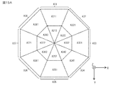
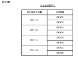
- the sensor unit 3011 has eight regions A31, A32, A33, when the living space is divided into eight regions A31, A32, A33, A34, A35, A36, A37, and A38 as shown in FIG. 15A, for example. ..., The temperature of each of A38 is detected. Then, as shown in FIG. 15B, for example, the area storage unit 3132 displays the area information for identifying the areas A31, A32, A33, ..., A38 in the living space, and the area information A31, A32, A33 in the display device 3001. , ..., The display unit identification information for identifying the display units 13a, 13b, 13c, and 13d provided on the side facing the A38 is stored in association with the display unit identification information.
- the area information includes information indicating the rotation angle of the sensor support base 3011c of the sensor unit 3011 from the initial position. Further, the area information includes, for example, when the display device 3001 is installed on the ceiling of the room, the installer sets the display device as eight areas A31, A32, A33, ..., A38 in the living space where the display device 1 is installed.
- the area storage unit 132 stores the information in association with the display unit identification information based on the positional relationship with the 3001.
- the angle storage unit 3133 stores information indicating a unit rotation angle when rotating the sensor support base 3011c and information indicating the initial position of the sensor support base 3011c.
- the temperature acquisition unit 3111 acquires the temperature information input from the sensor 3011a of the sensor unit 3011.
- the average temperature calculation unit 3112 calculates the average temperature of the temperatures in the two sub-regions included in each of the regions A31, A32, A33, ..., A38.
- the sensor unit 3011 rotates the sensor support base 3011c so that the two thermopile 30111s have subregions A311, A312, A321, A322, A331, A332, A341, A342, respectively.
- the temperatures in A351, A352, A361, A362, A371, A372, A381, and A382 are sequentially detected.
- the average temperature calculation unit 3112 calculates the average value of the temperatures of the sub-regions A311 and A312 as the temperature of the sub-region A31, and calculates the average value of the temperatures of the sub-regions A321 and A322 as the temperature of the region A32. Further, the average temperature calculation unit 3112 calculates the average value of the temperatures of the sub-regions A331 and A332 as the temperature of the sub-region A33, and calculates the average value of the temperatures of the sub-regions A341 and A342 as the temperature of the region A34.
- the average temperature calculation unit 3112 calculates the average value of the temperatures of the sub-regions A351 and A352 as the temperature of the sub-region A35, and calculates the average value of the temperatures of the sub-regions A361 and A362 as the temperature of the region A36. Further, the average temperature calculation unit 3112 calculates the average value of the temperatures of the sub-regions A371 and A372 as the temperature of the sub-region A37, and calculates the average value of the temperatures of the sub-regions A381 and A382 as the temperature of the region A38.
- the rotation command unit 3115 sends rotation command information for commanding the sensor support base 3011c to rotate by a unit rotation angle to the drive unit 3011b of the sensor unit 3011 based on the information indicating the unit rotation angle stored in the angle storage unit 3133. Output. Further, the rotation command unit 3115 outputs the command number information indicating the number of times the rotation command information is output to the drive unit 3011b from the state in which the sensor support base 3011c is set to the initial position to the display mode specifying unit 3113.
- the display mode specifying unit 3113 specifies the temperature detection target area of the sensor 3011a of the sensor unit 3011 based on the command number information input from the rotation command unit 3115. Then, the display mode specifying unit 3113 refers to the information indicating the reference temperature range stored in the temperature range storage unit 131, and whether or not the temperature indicated by the temperature information of the specified temperature detection target region is within the reference temperature range. By determining the above, the display mode of the display units 13a, 13b, 13c, and 13d corresponding to the temperature detection target region is specified. The display mode specifying unit 3113 specifies the display modes of the display units 13a, 13b, 13c, and 13d corresponding to the temperature detection target area each time the temperature detection target area of the sensor 3011a is switched.
- the display mode specifying unit 3113 determines that the temperature of the region A34 is within the reference temperature range among the temperatures of the eight regions A31, A32, A33, ..., A38 calculated by the average temperature calculation unit 3112, for example. To do. In this case, the display mode specifying unit 3113 specifies the display mode in which the display unit 13b is turned on with reference to the display unit identification information corresponding to the area information of the area A34 stored in the area storage unit 3132. Then, the display mode specifying unit 3113 outputs information indicating the specified display mode to the display control unit 114. At this time, the display control unit 114 turns on the display unit 13b by outputting the lighting command information to the lighting circuit 12b.
- this display control process is started when, for example, the power is turned on to the display device 3001.
- the rotation command unit 3115 moves the sensor support base 3011c of the sensor unit 3011 to the initial position (step S3101).
- the sensor 3011a is set so as to face the temperature detection target region (for example, region A31) corresponding to the initial position of the sensor support base 3011c.
- the temperature acquisition unit 3111 acquires the temperature information of the temperature detection target region detected by the sensor 3011a (step S3102).
- the average temperature calculation unit 3112 calculates the average temperature of the sub-regions (for example, sub-regions A311 and A312) included in the temperature detection target region (step S3103).
- the average temperature calculation unit 3112 calculates the average temperature of the two sub-regions included in the temperature detection target region as the temperature of the temperature detection target region.
- the display mode specifying unit 3113 determines whether or not the temperature of the temperature detection target region is within the reference temperature range (step S3104). When the display mode specifying unit 113 determines that the temperature of the temperature detection target region is out of the reference temperature range (step S3104: No), the process of step S3108 described later is executed as it is.
- the display mode specifying unit 3113 determines that the temperature of the temperature detection target region is within the reference temperature range (step S3104: Yes). In this case, the display mode specifying unit 3113 specifies a display mode for lighting the display unit (for example, the display unit 13a) corresponding to the temperature detection target area (step S3105). At this time, the display mode specifying unit 3113 acquires the display unit identification information of the display unit associated with the temperature detection target area by referring to the information stored in the area storage unit 3132. Then, the display mode specifying unit 3113 outputs the information indicating the display mode including the acquired display unit identification information and the information indicating the lighting associated therewith to the display control unit 114.
- the display control unit 114 generates command information including lighting command information of the display units 13a, 13b, 13c, and 13d based on the information indicating the display mode input from the display mode specifying unit 3113 (step S3106). ). Subsequently, the display control unit 114 outputs the generated command information to the corresponding lighting circuits 12a, 12b, 12c, and 12d (step S3107). After that, the rotation command unit 3115 determines whether or not the sensor support base 3011c has reached the preset end position (step S3108). Here, the rotation command unit 3115 determines that the end position has been reached when, for example, the number of times of output of the rotation command information indicated by the above-mentioned command number information reaches a preset number of times.
- step S3108: Yes the process of step S3101 is executed again.
- step S3108: No the rotation command unit 3115 rotates the sensor support base 3011c by a preset unit angle (step S3109).
- step S3109 the process of step S3102 is executed again.
- the sensor 3011a of the sensor unit 3011 sets the temperature of each of the eight regions A31, A32, A33, ..., A38 for each region. It will be detected in order. As a result, the number of thermopile 30111 used in the sensor unit 3011 can be reduced, and the configuration of the sensor unit 3011 can be simplified accordingly.
- the display device is detected by the environment information acquisition unit that acquires the second environment information indicating the second environment parameter detected in at least one device installed in the living space, and the environment detection unit.
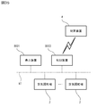
- the display device 4001 can communicate with the air conditioner 2 via the network NW laid in the building where the display device 4001 is installed.
- the network NW is a wired or wireless LAN (Local Area Network) conforming to a communication standard such as Ethernet (registered trademark).
- the air conditioner 2 includes an environmental measurement unit (not shown) that measures environmental parameters of the living space such as humidity and brightness of the living space, and provides environmental information indicating the environmental parameters measured by the environmental measurement unit. It has a function of transmitting to the display device 4001 via the network NW.
- an environmental measurement unit not shown
- environmental parameters of the living space such as humidity and brightness of the living space
- It has a function of transmitting to the display device 4001 via the network NW.
- one air conditioner 2 is installed in each of the four areas A1, A2, A3, and A4 in the living space, for example.
- the environmental parameters measured by the air conditioner 2 installed in the area A1 may be used as the environmental parameters in the area A1. That is, the environmental parameters measured by the air conditioners 2 installed in each of the four regions A1, A2, A3, and A4 may be the environmental parameters in the corresponding regions A1, A2, A3, and A4. Then, the environmental information may indicate the environmental parameters of each of the four regions A1, A2, A3, and A4.
- the control unit 4010 of the display device 4001 includes the MPU 101, the main storage unit 102, the auxiliary storage unit 103, the sensor interface 104, the display interface 105, and the communication interface 4107 connected to the network NW. And a bus 109 that connects them to each other.
- the auxiliary storage unit 103 stores a program for the MPU 101 to execute various processes.
- the communication interface 4107 is an interface conforming to the communication standard of the network NW, and when the device 2 receives the environmental information via the network NW, the received environmental information is converted and output to the MPU 101.
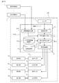
- the MPU 101 reads the program stored in the auxiliary storage unit 103 into the main storage unit 102 and executes it, so that the temperature acquisition unit 111, the display mode specifying unit 4113, the display control unit 114, and the environment information acquisition It functions as a unit 4116 and a discomfort index calculation unit 4117.
- the auxiliary storage unit 103 shown in FIG. 18 stores discomfort index range information indicating the discomfort index range with respect to the discomfort index that is a condition for lighting the display units 13a, 13b, 13c, and 13d. It has an exponential information storage unit 4134 and an area storage unit 132.
- the discomfort index is an index value indicating the quality of the environment in each of the regions A1, A2, A3, and A4.
- the environmental information acquisition unit 4116 acquires environmental information indicating environmental parameters in each of the regions A1, A2, A3, and A4 transmitted from the air conditioner 2.
- the discomfort index calculation unit 4117 is an index value calculation unit that calculates the discomfort index in each of the four regions A1, A2, A3, and A4 of the living space.
- the discomfort index calculation unit 4117 includes the temperatures of the sub-regions A11, A12, A13, ..., A44 indicated by the temperature information acquired by the temperature acquisition unit 111, and the environmental parameters indicated by the environmental information acquired by the environmental information acquisition unit 4116. And, the discomfort index in each of the four regions A1, A2, A3, and A4 is calculated from.
- the discomfort index calculation unit 4117 is, for example, the temperature of each of the sub-regions A11, A12, A13, and A14 indicated by the temperature information acquired by the temperature acquisition unit 111, and the region indicated by the environmental information acquired by the environmental information acquisition unit 4116.
- the discomfort index in the region A1 is calculated from the environmental parameters of A1.
- the environmental parameter used to calculate the discomfort index is humidity.
- the discomfort index is calculated using, for example, the relational expression of the following equation (1).
- F 0.81 ⁇ Th + 0.01 ⁇ HU ⁇ (0.99Th-14.3) +46.3 ⁇ ⁇ ⁇ Equation (1)
- F is a discomfort index
- Th temperature
- HU humidity.
- the display mode specifying unit 4113 refers to the discomfort index range information stored in the discomfort index information storage unit 4134, and is based on the discomfort index of each of the four regions A1, A2, A3, and A4 calculated by the discomfort index calculation unit 4117.
- the display modes of the four display units 13a, 13b, 13c, and 13d are specified. It is assumed that the display mode specifying unit 113 determines that the discomfort index of the region A4 is within the reference discomfort index range among the discomfort indexes of each of the four regions A1, A2, A3, and A4, for example.
- the display mode specifying unit 4113 turns on the display unit 13d and turns off the display units 13a, 13b, and 13c with reference to the display unit identification information corresponding to the area information of the area A4 stored in the area storage unit 132. Specify the display mode to be maintained in.
- the display control process executed by the display device 4001 according to the present embodiment will be described with reference to FIG.
- This display control process is started, for example, when the power is turned on to the display device 4001.
- the temperature acquisition unit 111 acquires the temperature information of each of the sub-regions A11, A12, A13, ..., A44 detected by the sensor 11 (step S4101).
- the discomfort index calculation unit 4117 the temperatures of the sub-regions A11, A12, A13, ..., A44 indicated by the temperature information acquired by the temperature acquisition unit 111 and the environmental information acquired by the environmental information acquisition unit 4116 are obtained. From the indicated environmental parameters, the discomfort index in each of the four regions A1, A2, A3, and A4 of the living space is calculated (step S4102).
- the display mode specifying unit 4113 determines whether or not there is a region in the regions A1, A2, A3, and A4 whose discomfort index is within the reference discomfort index range (step S4103).
- the display mode specifying unit 4113 determines that all the temperatures of the regions A1, A2, A3, and A4 are outside the reference discomfort index range (step S4103: No)
- the process of step S4101 is executed again.
- the display mode specifying unit 4113 determines that at least one of the areas A1, A2, A3, and A4 is within the reference discomfort index range (step S4103: Yes). In this case, the display mode specifying unit 4113 lights the display unit (for example, the display unit 13d) corresponding to the area where the discomfort index is within the reference discomfort index range with reference to the information stored in the area storage unit 132, and other than that.
- a display mode for maintaining the display unit (for example, display units 13a, 13b, 13c) corresponding to the region of is turned off is specified (step S4104). At this time, the display mode specifying unit 4113 outputs the display mode information including the display unit identification information of the display unit to be turned on and the display unit identification information of the display unit that maintains the extinguished state to the display control unit 114.
- the display control unit 114 After that, the display control unit 114 generates command information including lighting command information or extinguishing command information for each of the display units 13a, 13b, 13c, and 13d based on the display mode information input from the display mode specifying unit 113. (Step S4105). Next, the display control unit 114 outputs the generated command information to each of the lighting circuits 12a, 12b, 12c, and 12d (step S4106). Subsequently, the process of step S4101 is executed again.
- the environmental information acquisition unit 4116 acquires environmental information indicating the environmental parameters detected by the air conditioner 2 installed in the living space. Further, the discomfort index calculation unit 4117 is based on the temperatures of the four regions A1, A2, A3, and A4 detected by the sensor 11 and the environmental parameters indicated by the environmental information acquired by the environmental information acquisition unit 4116. The discomfort index of each of the two regions A1, A2, A3, and A4 is calculated. Then, the display mode specifying unit 4113 specifies the display mode of the display units 13a, 13b, 13c, 13d based on the discomfort index of each of the four regions A1, A2, A3, and A4. As a result, the user can recognize the comfort of each of the four areas A1, A2, A3, and A4 of the living space only by confirming the display modes of the four display units 13a, 13b, 13c, and 13d.
- the display device is different from the fourth embodiment in that the display mode specifying unit specifies the display mode of the display unit based on the first environmental parameter together with the index values of each of the plurality of regions. ..
- the display device can communicate with the air conditioner 2 via the network NW, similarly to the display device 4001 according to the fourth embodiment.
- the hardware configuration of the control unit of the display device is the same as that of the control unit 4010 according to the fourth embodiment, and the MPU, the main storage unit, the auxiliary storage unit, the sensor interface, the display interface, the communication interface, and these are connected to each other. Equipped with a bus to interface.
- the auxiliary storage unit stores a program for the MPU to execute various processes.
- the MPU reads the program stored in the auxiliary storage unit into the main storage unit and executes it, so that the temperature acquisition unit 111, the average temperature calculation unit 112, the display mode specifying unit 5113, and the display control unit 5114 , It functions as an environmental information acquisition unit 4116 and a discomfort index calculation unit 4117.
- the same reference numerals as those in FIG. 19 are attached to the same configurations as those in the fourth embodiment.
- the auxiliary storage unit 103 includes a temperature range storage unit 131, an area storage unit 132, and a discomfort index information storage unit 4134.
- the display mode specifying unit 5113 refers to the reference temperature range stored in the temperature range storage unit 131 and the discomfort index range information stored in the discomfort index information storage unit 4134, and refers to each of the four regions A1, A2, A3, and A4. Based on the discomfort index and temperature, the display modes of the four display units 13a, 13b, 13c, and 13d are specified. It is assumed that the display mode specifying unit 5113 determines that the temperatures of the regions A1, A2, A3, and A4 are within the reference temperature range, and the discomfort index is also within the reference discomfort index range. In this case, as shown in FIG.
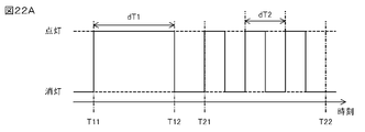
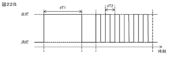
- the display mode specifying unit 5113 lights the display units 13a, 13b, 13c, and 13d for a preset period dT1 from the time T11 to the time T12, and then after the time T12. In the period between the time T21 and the time T22, the display mode in which the display units 13a, 13b, 13c, and 13d are blinked in the cycle dT2 is specified.
- the display mode specifying unit 5113 changes the blinking cycle dT2 according to the magnitude of the discomfort index. As shown in FIG. 22B, for example, the display mode specifying unit 5113 shortens the blinking cycle dT2 as the magnitude of the discomfort index increases within the reference discomfort index range.
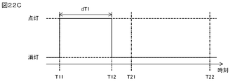
- the display mode specifying unit 5113 determines that the temperatures of the regions A1, A2, A3, and A4 are within the reference temperature range and the discomfort index is outside the reference discomfort index range.
- the display mode specifying unit 5113 lights the display units 13a, 13b, 13c, and 13d for a preset period dT1 from the time T11 to the time T12, and then displays the display unit 13a.
- 13b, 13c, 13d are specified in a display mode in which the lights are kept off.
- the display mode specifying unit 5113 determines that the temperatures of the regions A1, A2, A3, and A4 are outside the reference temperature range and the discomfort index is within the reference discomfort index range.
- the display mode specifying unit 5113 maintains the display units 13a, 13b, 13c, and 13d in the extinguished state for a preset period dT1 from the time T11 to the time T12, as shown in FIG. 22D, for example.
- the display mode in which the display units 13a, 13b, 13c, and 13d are blinked in the cycle dT2 is specified.
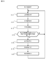
- the display control process executed by the display device 5001 according to the present embodiment will be described with reference to FIG.
- This display control process is started, for example, when the power is turned on to the display device 5001.
- the temperature acquisition unit 111 acquires the temperature information of each of the sub-regions A11, A12, A13, ..., A44 detected by the sensor 11 (step S5101).
- the average temperature calculation unit 112 calculates the average temperature of the sub-regions A11, A12, A13, ..., A44 included in each of the regions A1, A2, A3, and A4 (step S5102).
- the temperatures of the sub-regions A11, A12, A13, ..., A44 indicated by the temperature information acquired by the temperature acquisition unit 111 and the environmental information acquired by the environmental information acquisition unit 4116 are obtained.
- the discomfort index in each of the regions A1, A2, A3, and A4 is calculated from the indicated environmental parameters (step S5103).
- the display mode specifying unit 4113 determines whether or not there is a region where the temperature is within the reference temperature range or a region where the discomfort index is within the reference discomfort index range in the regions A1, A2, A3, and A4 (step). S5104).
- step S5104 determines that all the temperatures of the regions A1, A2, A3, and A4 are out of the reference temperature range and all the discomfort indexes are out of the reference discomfort index range (step S5104: No), it is again.
- the process of step S5101 is executed.
- the display mode specifying unit 4113 determines that there is at least one region in the regions A1, A2, A3, and A4 whose temperature is within the reference temperature range or whose discomfort index is within the reference discomfort index range (). Step S54104: Yes). In this case, the display mode specifying unit 4113 lights the display unit corresponding to the area where the temperature is within the reference temperature range with reference to the information stored in the area storage unit 132, and the discomfort index is within the reference discomfort index range. The display mode in which the display unit corresponding to the area is blinking is specified (step S5105). At this time, the display mode specifying unit 4113 outputs the display mode information including the display unit identification information of the display unit to be turned on or blinked and the display unit identification information of the display unit that maintains the extinguished state to the display control unit 5114.
- the display control unit 5114 gives a command including lighting command information, blinking command information, or extinguishing command information for each of the display units 13a, 13b, 13c, and 13d based on the display mode information input from the display mode specifying unit 113. Information is generated (step S5106). Next, the display control unit 5114 outputs the generated command information to each of the lighting circuits 12a, 12b, 12c, and 12d (step S5107). Subsequently, the process of step S5101 is executed again.
- the display mode specifying unit 5113 has the display units 13a and 13b based on the discomfort index and temperature of each of the four regions A1, A2, A3 and A4. , 13c, 13d are specified.
- the user can recognize the temperature and comfort of each of the four areas A1, A2, A3, and A4 of the living space simply by checking the display modes of the four display units 13a, 13b, 13c, and 13d. Can be done.
- the method of displaying the humidity of the living space or the discomfort index of each of the areas A1, A2, A3, and A4 is, for example, the higher the humidity or discomfort index, the darker purple is displayed, and when the humidity or discomfort index is lower, the color is white. It is preferable to distinguish the temperature from the display color of red or blue by displaying with.
- the control system includes at least one device installed in the living space and a display device.
- the display device has a display mode of at least one display unit based on an environment detection unit, at least one display unit, and first environment information indicating first environment parameters for each of a plurality of regions detected by the environment detection unit.
- a display mode specifying unit for specifying the above-mentioned display mode, and a display control unit for controlling at least one display unit so as to have the above-mentioned display mode.
- the display device further includes a control information generation unit that generates control information for controlling at least one device based on the first environmental parameter.
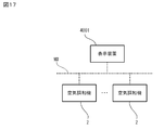
- the control system includes an air conditioner 2 provided with four outlets 2a, 2b, 2c, and 2d, and a display device 6001.
- the air conditioner 2 and the display device 6001 can communicate with each other via a network (not shown).
- the air conditioner 2 can operate at least in the operation mode of the cooling mode and the heating mode.
- the air conditioner 2 receives the control information from the display device 6001, the air conditioner 2 separately adjusts the temperature of the air discharged from the four outlets 2a, 2b, 2c, and 2d based on the received control information.
- the temperature of the region A61 including the regions A12 and A21 and a part of the regions A11, A13, A22 and A24 can be changed.
- the temperature of the region A62 including the regions A23 and A32 and a part of the regions A22, A24, A31 and A33 can be changed.
- the temperature of the region A63 including the regions A43 and A34 and a part of the regions A31, A33, A42 and A44 can be changed.
- the temperature of the region A64 including the regions A41 and A14 and a part of the regions A42, A44, A11 and A13 can be changed.
- the air conditioner 2 receives the operation state information request information requesting the display device 6001 to transmit the operation state information indicating the operation state of the own machine, the air conditioner 2 generates the operation state information and transmits the operation state information to the display device 6001. .
- the operation state information includes operation mode information indicating the operation mode of the air conditioner 2 and set temperature information indicating the set temperature of the air discharged from each of the four outlets 2a, 2b, 2c, and 2d. Including.
- the hardware configuration of the display device 6001 is the same as that of the display device 4001 according to the fourth embodiment, and the control unit 6010 shown in FIG. 25 includes an MPU, a main storage unit, an auxiliary storage unit, a sensor interface, a display interface, and a communication interface. And a bus connecting them to each other.
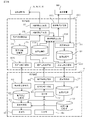
- the auxiliary storage unit stores a program for the MPU to execute various processes. By reading the program stored in the auxiliary storage unit into the main storage unit and executing the MPU, the temperature acquisition unit 111, the average temperature calculation unit 6112, the display mode specifying unit 113, the display control unit 114, the operating state acquisition unit 6118, It functions as a determination unit 6119, a control information generation unit 6120, and a control information transmission unit 6121.
- the auxiliary storage unit includes a temperature range storage unit 131, an area storage unit 6132, and an operation state storage unit 6135 that stores the operation state information of the air conditioner 2.
- the area storage unit 6132 provides area information for identifying the areas A61, A62, A63, and A64 in the living space to the display units 13a and 13b provided on the side facing the areas A61, A62, A63, and A64 in the display device 6001. , 13c, 13d are stored in association with the display unit identification information that identifies them.
- the area information is, for example, when the display device 6001 is installed on the ceiling of the room, the installer sets the positions of the areas A61, A62, A63, A64 and the display device 6001 in the living space where the display device 6001 is installed. It is stored in the area storage unit 6132 in association with the display unit identification information based on the relationship.
- the operation state storage unit 6135 includes operation mode information indicating the operation mode of the air conditioner 2, set temperature information indicating the set temperature of the air discharged from the outlets 2a, 2b, 2c, and 2d of the air conditioner 2.
- the operation state storage unit 6135 associates the operation mode information and the set temperature information with the outlet identification information and the area information for identifying the outlets 2a, 2b, 2c, and 2d of the air conditioner 2, respectively. I remember.
- the average temperature calculation unit 6112 calculates the average temperature of the sub-regions A12, A21, A11, A13, A22, and A24 as the temperature of the region A61. That is, the average temperature calculation unit 6112 calculates the average temperature including the temperature of the sub-region that straddles both of the adjacent regions. Further, the average temperature calculation unit 6112 calculates the average temperature of the region subs A23, A32, A22, A24, A31, and A33 as the temperature of the region A62. Further, the average temperature calculation unit 6112 calculates the average temperature of the sub-regions A43, A34, A31, A33, A42, and A44 as the temperature of the region A63. Further, the average temperature calculation unit 6112 calculates the average temperature of the sub-regions A41, A14, A42, A44, A11, and A13 as the temperature of the region A64.
- the operating state acquisition unit 6118 acquires the operating state information transmitted from the air conditioner 2 by transmitting the operating state information request information to the air conditioner 2.
- the operation state acquisition unit 6118 extracts the operation mode information and the set temperature information from the acquired operation state information and stores them in the operation state storage unit 6135.
- the operating state acquisition unit 6118 stores the extracted set temperature information in the operating state storage unit 6135 in association with the outlet identification information for identifying the outlets 2a, 2b, 2c, and 2d of the air conditioner 2. ..
- the control information generation unit 6120 generates control information for controlling the operation of the air conditioner 2.
- control information includes outlet identification information for identifying the outlets 2a, 2b, 2c, and 2d of the air conditioner 2, and set temperature information corresponding to the outlets 2a, 2b, 2c, and 2d.
- the control information transmission unit 6121 transmits the control information generated by the control information generation unit 6120 to the air conditioner 2.
- the determination unit 6119 operates the air conditioner 2 based on the operating states of the air conditioner 2 indicated by the operating state information stored in the operating state storage unit 6135 together with the temperatures of the four regions A61, A62, A63, and A64. It is determined whether or not to generate control information for changing the state, that is, the set temperature of the air discharged from the outlets 2a, 2b, 2c, and 2d. Specifically, the determination unit 6119 includes the temperatures of the four regions A61, A62, A63, and A64, the operation mode of the air conditioner 2, and the set temperature information corresponding to the outlets 2a, 2b, 2c, and 2d. Based on, it is determined whether or not it is necessary to generate the above-mentioned control information.
- the control information generation unit 6120 generates the control information.
- the control information generation unit 6120 avoids the generation of the control information when the determination unit 6119 determines that it is not necessary to generate the control information.
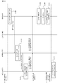
- the display device 6001 determines that the temperature of at least one region (for example, region A62) of the regions A61, A62, A63, and A64 is within the reference temperature range, and the temperature is within the reference temperature range (region (for example, region A62)). For example, it is assumed that the display unit (for example, the display unit 13b) corresponding to the area A61) is turned on (step S61). Next, the operation state information request information requesting the air conditioner 2 to transmit the operation state information indicating the operation state of the air conditioner 2 is transmitted from the display device 6001 to the air conditioner 2 (step S62). ..
- the air conditioner 2 when the air conditioner 2 receives the operation state information request information, the air conditioner 2 generates the operation state information including the operation mode information of the own machine and the set temperature information corresponding to each of the outlets 2a, 2b, 2c, and 2d (Ste S63). Subsequently, the generated operating state information is transmitted from the air conditioner 2 to the display device 6001 (step S64).
- the display device 6001 when the display device 6001 receives the operation state information, the display device 6001 extracts the operation mode information and the set temperature information from the received operation state information and stores them in the operation state storage unit 6135.
- step S65 the display device 6001 determines that the air conditioner 2 is operating in the heating mode with reference to the operation mode information stored in the operation state storage unit 6135. Then, the display device 6001 detects the set temperature ThA of the air discharged from the corresponding outlet (for example, outlet 2b) in at least one region (for example, region A62) of the regions A61, A62, A63, and A64. It is assumed that it is determined that the temperature is higher than the temperature ThS detected by No. 11 (step S66).
- the display device 6001 sets the set temperature of the air discharged from the outlet to 1 ° C., which corresponds to the region where the set temperature ThA of the air discharged from the outlet is determined to be higher than the temperature detected by the sensor 11. Generate control information for raising (step S67). Next, the generated control information is transmitted from the display device 6001 to the air conditioner 2 (step S68). On the other hand, when the air conditioner 2 receives the control information from the display device 6001, the air conditioner 2 updates the control information of its own unit using the received control information (step S69). For example, suppose that the target temperature of the region A62 is 26 ° C, while the actual temperature of the region A62 is 30 ° C. In this case, the display device 6001 lowers the set temperature of the air discharged from the outlet 2b of the air conditioner 2.
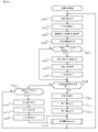
- the temperature acquisition unit 111 acquires the temperature information of each of the sub-regions A11, A12, A13, ..., A44 detected by the sensor 11 (step S6101).
- the average temperature calculation unit 6112 calculates the average temperature of the sub-regions A11, A12, A13, ..., A44 corresponding to each of the regions A61, A62, A63, and A64 (step S6102).
- the average temperature calculation unit 6112 calculates the average temperature of the sub-region corresponding to each of the above-mentioned regions A61, A62, A63, and A64 as the temperature of each of the regions A61, A62, A63, and A64. Subsequently, the display mode specifying unit 113 determines whether or not the temperatures of the regions A61, A62, A63, and A64 are within the reference temperature range (step S6103). When the display mode specifying unit 113 determines that all the temperatures of the regions A61, A62, A63, and A64 are outside the reference temperature range (step S6103: No), the process of step S6101 is executed again.
- the display mode specifying unit 113 determines that the temperature of at least one of the regions A61, A62, A63, and A64 is within the reference temperature range (step S6103: Yes).
- the display mode specifying unit 113 refers to the information stored in the area storage unit 6132 to light the display unit (for example, the display unit 13b) corresponding to the region whose temperature is within the reference temperature range, and other regions.
- display units 13a, 13c, 13d) corresponding to the above are specified in a display mode in which the display units (for example, display units 13a, 13c, 13d) are maintained in a light-off state (step S6104).
- the display control unit 114 After that, the display control unit 114 generates command information including lighting command information or extinguishing command information for each of the display units 13a, 13b, 13c, and 13d based on the display mode information input from the display mode specifying unit 113. (Step S6105). Next, the display control unit 114 outputs the generated command information to each of the lighting circuits 12a, 12b, 12c, and 12d (step S6106). Subsequently, the operating state acquisition unit 6118 acquires the operating state information from the air conditioner 2 by transmitting the operating state information request information to the air conditioner 2 (step S6107) (step S6108). Here, the operation state acquisition unit 6118 extracts the operation mode information and the set temperature information from the acquired operation state information and stores them in the operation state storage unit 6135.
- the determination unit 6119 determines whether or not the operation mode of the air conditioner 2 is the heating mode with reference to the operation mode information stored in the operation state storage unit 6135 (step S6201).
- the determination unit 6119 determines that the operation mode of the air conditioner 2 is the heating mode (step S6201: Yes).
- the determination unit 6119 refers to the set temperature information stored in the operation state storage unit 6135, and refers to the air discharged from the corresponding outlet for at least one region of the regions A61, A62, A63, and A64.
- step S6202 It is determined whether or not the set temperature ThA of the above is higher than the temperature ThS detected by the sensor 11 (step S6202).
- the determination unit 6119 determines that the set temperature ThA of the air discharged from the corresponding outlets is equal to or lower than the temperature ThS detected by the sensor 11 in all of the regions A61, A62, A63, and A64 (step). S6202: No), the process of step S6101 of FIG. 27 is executed again.
- the determination unit 6119 detected the set temperature ThA of the air discharged from the corresponding outlet for at least one region of the regions A61, A62, A63, and A64 by the sensor 11. If it is determined that the temperature is higher than ThS (step S6202: Yes). In this case, the control information generation unit 6120 sets the set temperature of the air discharged from the outlet corresponding to the region where the set temperature ThA of the air discharged from the outlet is determined to be higher than the temperature detected by the sensor 11. Generate control information for raising the temperature by 1 ° C. (step S6203). Subsequently, the control information transmission unit 6121 transmits the control information generated by the control information generation unit 6120 to the air conditioner 2 (step S6207).
- step S6201 when the determination unit 6119 determines that the operation mode of the air conditioner 2 is an operation mode other than the heating mode (step S6201: No), whether the operation mode of the air conditioner 2 is the cooling mode. Whether or not it is determined (step S6204).
- step S6204: No when the determination unit 6119 determines that the operation mode of the air conditioner 2 is neither the cooling mode nor the heating mode (step S6204: No), the process of step S6101 of FIG. 27 is executed again.
- the determination unit 6119 determines that the operation mode of the air conditioner 2 is the cooling mode (step S6204: Yes).
- the determination unit 6119 refers to the set temperature information stored in the operation state storage unit 6135, and refers to the air discharged from the corresponding outlet for at least one region of the regions A61, A62, A63, and A64. It is determined whether or not the set temperature ThA of the above is lower than the temperature ThS detected by the sensor 11 (step S6205).
- the determination unit 6119 determines that the set temperature ThA of the air discharged from the corresponding outlets is equal to or higher than the temperature ThS detected by the sensor 11 in all of the regions A61, A62, A63, and A64 (step). S6205: No), the process of step S6101 of FIG. 27 is executed again.
- the determination unit 6119 detected the set temperature ThA of the air discharged from the corresponding outlet for at least one region of the regions A61, A62, A63, and A64 by the sensor 11. If it is determined that the temperature is lower than ThS (step S6205: Yes). In this case, the control information generation unit 6120 sets the set temperature of the air discharged from the outlet corresponding to the region where the set temperature ThA of the air discharged from the outlet is lower than the temperature detected by the sensor 11. Generate control information for lowering by 1 ° C. (step S6206). Subsequently, the control information transmission unit 6121 transmits the control information generated by the control information generation unit 6120 to the air conditioner 2 (step S6207). After that, the process of step S6101 of FIG. 27 is executed again.
- the control information generation unit 6120 generates control information for controlling the air conditioner 2 based on the temperatures of the regions A61, A62, and A63. ..
- the temperatures of the four regions A61, A62, A63, and A64 of the living space by the sensor 11 can be maintained at appropriate temperatures, so that the temperature of the living space can be maintained at a comfortable temperature.
- the set temperature of the air conditioner 2 and the temperature detected by the sensor 11 deviate from each other, the set temperature of the air conditioner 2 is adjusted so that the temperature detected by the sensor 11 approaches the target temperature. You may. In this case, there is an advantage that each of the living space areas A61, A62, A63, and A64 can be maintained at a comfortable temperature.
- the determination unit 6119 determines whether or not it is necessary to generate control information based on the temperatures of the regions A61, A62, A63, and A64.
- the determination unit 6119 generates control information based on the operating state of the air conditioner 2 indicated by the operating state information, that is, the operating mode and the set temperature, together with the temperatures of the regions A61, A62, A63, and A64. Judge whether or not. Then, when the control information generation unit 6120 determines that the determination unit 6119 needs to generate the control information, the control information generation unit 6120 generates the control information, and the determination unit 6119 determines that it is not necessary to generate the control information. , Avoid the generation of control information. As a result, it is suppressed that the display device 6001 transmits unnecessary control information to the air conditioner 2, so that there is an advantage that the communication traffic between the display device 6001 and the air conditioner 2 can be reduced. is there.
- the control system includes a control device, and the control device provides temperature information for each of a plurality of areas in the living space acquired from the display device and operating state information acquired from at least one device. Based on this, the control information of at least one device is generated, which is different from the sixth embodiment.
- the control system includes a display device 7001, an air conditioner 2 and a control device 3 connected to each other via a network NW.
- a display device 7001 an air conditioner 2 and a control device 3 connected to each other via a network NW.
- the control unit 7010 shown in FIG. 30 includes an MPU, a main storage unit, an auxiliary storage unit, a sensor interface, a display interface, and a communication interface. And a bus connecting them to each other.
- the auxiliary storage unit stores a program for the MPU to execute various processes.
- the auxiliary storage unit stores a program for the MPU to execute various processes.
- the temperature acquisition unit 111 By reading the program stored in the auxiliary storage unit into the main storage unit and executing the MPU, the temperature acquisition unit 111, the average temperature calculation unit 112, the display mode specifying unit 113, the display control unit 114, the temperature information generation unit 7122, and the temperature information generation unit 7122 It functions as a temperature information transmission unit 7123.
- the same reference numerals as those in FIGS. 5 and 25 are attached to the same configurations as those in the first and sixth embodiments.
- the temperature information generation unit 7122 generates temperature information indicating the temperatures of the regions A1, A2, A3, and A4 calculated by the average temperature calculation unit 112.
- the temperature information transmission unit 7123 transmits the temperature information generated by the temperature information generation unit 7122 to the control device 3.
- the control device 3 includes a CPU (Central Processing Unit) 301, a main storage unit 302, an auxiliary storage unit 303, a communication interface 307 connected to a network NW, and a bus connecting these to each other. 309 and.
- the auxiliary storage unit 303 stores a program for the CPU 301 to execute various processes.
- the CPU 301 reads the program stored in the auxiliary storage unit 303 into the main storage unit 302 and executes the program, so that the temperature acquisition unit 311, the operation state acquisition unit 318, the determination unit 319, and the control information generation unit are executed. It functions as 320 and the control information transmission unit 321.
- the temperature storage unit 331 stores the temperature information of each of the regions A1, A2, A3, and A4 acquired from the display device 7001 in association with the region information indicating the regions A1, A2, A3, and A4.
- the operation state storage unit 335 stores the operation state information of the air conditioner 2, that is, the operation mode information and the set temperature information in association with the device identification information of the air conditioner 2.
- the temperature acquisition unit 311 acquires the temperature information transmitted from the display device 7001 to the control device 3.
- the operation state acquisition unit 318 acquires the operation state information transmitted from the air conditioner 2 by transmitting the operation state information request information to each air conditioner 2.
- the operation state acquisition unit 318 extracts the operation mode information and the set temperature information from the acquired operation state information and stores them in the operation state storage unit 335.
- the operation state acquisition unit 318 operates by associating the extracted operation mode information and set temperature information with the device identification information of each of the air conditioners 2 installed in the areas A1, A2, A3, and A4. It is stored in the state storage unit 335.
- the control information generation unit 320 generates control information for controlling the operation of the air conditioner 2.
- the control information includes device identification information of the air conditioner 2 and set temperature information of the air conditioner 2.
- the control information transmission unit 321 transmits the control information generated by the control information generation unit 320 to the air conditioner 2.
- the determination unit 319 changes the operating state of the air conditioner 2, that is, the set temperature, based on the operation mode and set temperature of the air conditioner 2 and the temperatures of the four regions A1, A2, A3, and A4. It is determined whether or not it is necessary to generate the control information to be transmitted to the air conditioner 2 in order to perform the control information. Then, when the determination unit 319 determines that the control information generation unit 320 needs to generate the control information, the control information generation unit 320 generates the control information. On the other hand, when the determination unit 319 determines that the control information generation unit 320 does not need to generate the control information, the control information generation unit 320 avoids the generation of the control information.
- the display device 7001 determines that the temperature of at least one of the regions A1, A2, A3, and A4 is within the reference temperature range, and displays the display unit corresponding to the region where the temperature is within the reference temperature range. It is assumed that the light is turned on (step S71).
- the display device 7001 generates temperature information indicating the temperature of the regions A1, A2, A3, and A4 (step S72).
- the generated temperature information is transmitted from the display device 7001 to the control device 3 (step S73).
- the operation state information request information requesting the air conditioner 2 to transmit the operation state information is transmitted from the control device 3 to the air conditioner 2 (step S74).
- the air conditioner 2 when the air conditioner 2 receives the operation state information request information, the air conditioner 2 generates the operation state information including the operation mode information and the set temperature information of the own machine (step S75). Subsequently, the generated operating state information is transmitted from the air conditioner 2 to the control device 3 (step S76). On the other hand, when the control device 3 receives the operation state information, the control device 3 extracts the operation mode information and the set temperature information from the received operation state information and stores them in the operation state storage unit 335.
- control device 3 refers to the operation mode information stored in the operation state storage unit 335 and determines that the air conditioner 2 is operating in the heating mode (step S77). Then, the control device 3 determines that the set temperature ThA of the corresponding air conditioner 2 is higher than the temperature ThS detected by the sensor 11 in at least one region of the regions A1, A2, A3, and A4. (Step S78). In this case, the control device 3 generates control information for raising the set temperature of the air conditioner 2 by 1 ° C. corresponding to the region where the set temperature ThA is determined to be higher than the temperature detected by the sensor 11 (step). S79). Next, the generated control information is transmitted from the control device 3 to the air conditioner 2 (step S80). On the other hand, when the air conditioner 2 receives the control information from the control device 3, the air conditioner 2 updates the control information of its own machine using the received control information (step S81).
- the temperature acquisition unit 311 acquires the temperature information of each of the regions A1, A2, A3, and A4 from the display device 7001 (step S7301).
- the operating state acquisition unit 318 acquires the operating state information from the air conditioner 2 by transmitting the operating state information request information to the air conditioner 2 (step S7302) (step S7303).
- the operation state acquisition unit 318 extracts the operation mode information and the set temperature information from the acquired operation state information and stores them in the operation state storage unit 335.
- the control information generation process is executed (step S7304). This control information generation process is the same as the control information generation process described in the sixth embodiment.
- the device control process for controlling the air conditioner 2 is executed in the control device 3.
- the processing executed by the display device 7001 is simplified, so that the processing load on the display device 7001 is reduced.
- control system When the control system according to the present embodiment receives the first environment information indicating the first environment parameters of each of the plurality of areas when the living space is divided into a plurality of areas, the user receives the information regarding the received first environment information. It is different from the control system according to the seventh embodiment in that it is provided with a terminal device that sends out operation information indicating the operation content when the user operates the system.
- the control system includes an air conditioner 2 installed in a living space, a display device 8001, a control device 8003, and a terminal device 4.
- the same reference numerals as those in FIG. 29 are attached to the same configurations as those in the seventh embodiment.
- the display device 8001, the air conditioner 2 and the control device 3 are connected to each other via a network NW.
- the terminal device 4 is capable of wireless communication with the control device 3.
- One air conditioner 2 is installed in each of the four areas A1, A2, A3, and A4.
- the hardware configuration of the display device 8001 is the same as that of the display device 4001 according to the fourth embodiment.
- the light emitting devices of the display units 13a, 13b, 13c, and 13d each have the above-mentioned three types of light emitting elements.
- the lighting circuits 12a, 12b, 12c, and 12d have red light, yellow light, and yellow light by adjusting the ratio of the light emission intensities of the three types of light emitting elements for the light emitting devices of the display units 13a, 13b, 13c, and 13d, respectively. It emits one of four types of light, green light and blue light.
- the control unit 8010 shown in FIG. 36 includes an MPU, a main storage unit, an auxiliary storage unit, a sensor interface, a display interface, a communication interface, and a bus connecting them to each other.
- the auxiliary storage unit stores a program for the MPU to execute various processes.
- the MPU reads the program stored in the auxiliary storage unit into the main storage unit and executes it, so that the temperature acquisition unit 111, the average temperature calculation unit 112, the display mode acquisition unit 8124, the display control unit 114, the temperature information generation unit 7122, and the temperature information generation unit 7122 It functions as a temperature information transmission unit 7123.
- the same reference numerals as those in FIGS. 5 and 30 are attached to the same configurations as those in the first and seventh embodiments.
- the display mode acquisition unit 8124 acquires display mode information indicating the display modes of the display units 13a, 13b, 13c, and 13d transmitted from the control device 8003, and outputs the acquired display mode information to the display control unit 114.
- the control device 8003 includes a CPU 301, a main storage unit 302, an auxiliary storage unit 303, a communication interface 307 connected to the network NW, a wireless module 8308, and a bus 309 connecting them to each other.
- the auxiliary storage unit 303 stores a program for the CPU 301 to execute various processes.
- the CPU 301 reads the program stored in the auxiliary storage unit 303 into the main storage unit 302 and executes the program, so that the temperature acquisition unit 311, the temperature information transmission unit 8322, the operation state acquisition unit 318, and the operation state are executed.
- the auxiliary storage unit 303 shown in FIG. 37 includes a temperature storage unit 331, an operating state storage unit 335, and an arrangement storage unit 8336. As shown in FIG.
- the arrangement storage unit 8336 emits arrangement information indicating the arrangement of the air conditioners 2 installed in each of the areas A1, A2, A3, and A4 from the display units 13a, 13b, 13c, and 13d. It is stored in association with the display color identification information that identifies the color of the light.
- the arrangement information is the area information indicating the areas A1, A2, A3, and A4 and the device knowledge information that identifies the air conditioner 2 installed in each of the areas A1, A2, A3, and A4. This is information associated with the display unit identification information that identifies 13b, 13c, and 13d.
- the temperature acquisition unit 311 acquires the temperature information of each of the areas A1, A2, A3, and A4 transmitted from the display device 8001 to the control device 3. Then, the temperature acquisition unit 311 stores the acquired temperature information of each of the regions A1, A2, A3, and A4 in the temperature storage unit 331 in association with the region information of each of the regions A1, A2, A3, and A4.
- the temperature information transmission unit 8322 receives the temperature information request information requesting the transmission of the temperature information from the terminal device 4
- the temperature information transmission unit 8322 transmits the temperature information stored in the temperature storage unit 331 to the terminal device 4. That is, the temperature information transmission unit 8322 is an environmental parameter transmission unit that transmits the temperature information of each of the regions A1, A2, A3, and A4 detected by the sensor 11 to the terminal device 4.
- the operating state acquisition unit 318 acquires the operating state information transmitted from the air conditioner 2 by transmitting the operating state information request information to each air conditioner 2.
- the operation state acquisition unit 318 extracts the operation mode information and the set temperature information from the acquired operation state information and stores them in the operation state storage unit 335.
- the operation state acquisition unit 318 operates by associating the extracted operation mode information and set temperature information with the device identification information of each of the air conditioners 2 installed in the areas A1, A2, A3, and A4. It is stored in the state storage unit 335.
- the operation state transmission unit 8323 When the operation state transmission unit 8323 receives the operation state information request information requesting the transmission of the operation state information from the terminal device 4, the operation state information transmission unit 8323 stores the operation mode information and the set temperature information of each air conditioner 2 stored in the operation state storage unit 335. It is transmitted to the terminal device 4.
- the display mode generation unit 8324 has four display units 13a, 13b, and 13c based on the arrangement information indicating the arrangement of the air conditioners 2 installed in each of the areas A1, A2, A3, and A4 stored in the arrangement storage unit 8336. , 13d, generate display mode information indicating the display mode.
- the display mode information includes display color identification information indicating the emission color of each of the four display units 13a, 13b, 13c, and 13d.
- the display mode generation unit 8324 provides display mode information including lighting state command information for commanding the lighting states of the display units 13a, 13b, 13c, and 13d based on the device identification information input from the control information generation unit 320. Generate.
- the display mode transmission unit 8325 transmits the display mode information generated by the display mode generation unit 8324 to the display device 8001.
- the operation information acquisition unit 8326 acquires the operation information transmitted from the terminal device 4 and outputs the acquired operation information to the control information generation unit 320.
- the control information generation unit 320 generates control information for controlling the air conditioner 2 based on the operation information acquired from the terminal device 4 by the operation information acquisition unit 8326. Further, the control information generation unit 320 outputs the device identification information of the air conditioner 2 to be controlled by the generated control information to the display mode generation unit 8324.
- the control information transmission unit 321 transmits the control information generated by the control information generation unit 320 to the air conditioner 2.
- the terminal device 4 is, for example, a tablet-type mobile terminal, which includes a CPU 401, a main storage unit 402, an auxiliary storage unit 403, a display unit 404, an input unit 405, a wireless module 408, and the like.
- the auxiliary storage unit 403 stores a program for the CPU 401 to execute various processes.
- the display unit 404 is a display device such as a liquid crystal display or an organic EL display.
- the input unit 405 is, for example, a transparent touch pad arranged so as to be superimposed on the display unit 404. As shown in FIG.
- the CPU 401 reads the program stored in the auxiliary storage unit 403 into the main storage unit 402 and executes it, so that the temperature acquisition unit 411, the operation state acquisition unit 412, the display control unit 413, and the reception unit 414 are executed. , It functions as an operation information generation unit 415 and an operation information transmission unit 416.
- the auxiliary storage unit 403 shown in FIG. 37 has a temperature storage unit 431, an operating state storage unit 432, and a display position storage unit 433, as shown in FIG. 38. As shown in FIG.
- the display position storage unit 433 provides display position information indicating a display position corresponding to each of the areas A1, A2, A3, and A4 on the display unit 404, such as area information, display unit identification information, and equipment. It is stored in association with the knowledge information and the display color identification information.
- the temperature acquisition unit 411 acquires the temperature information from the control device 8003 by transmitting the temperature information request information described above to the control device 8003.
- the temperature acquisition unit 411 acquires the temperature information from the control device 8003 by transmitting the temperature information request information to the control device 8003.
- the temperature acquisition unit 411 stores the acquired temperature information of each of the areas A1, A2, A3, and A4 in the temperature storage unit 431 in association with the area information indicating the areas A1, A2, A3, and A4.
- the operation state acquisition unit 412 provides the operation mode information of the air conditioner 2 installed in each of the areas A1, A2, A3, and A4 from the control device 8003. Acquire the set temperature information.
- the operation state acquisition unit 412 stores the acquired operation mode information and set temperature information of each air conditioner 2 in the operation state storage unit 432 in association with the device identification information of the air conditioner 2.
- the display control unit 413 stores the temperature information of each of the areas A1, A2, A3, and A4 stored in the temperature storage unit 431 and the operation state storage unit 432 based on the display position information stored in the display position storage unit 433.
- the operation screen image is displayed on the display unit 404 with reference to the operation mode information and the set temperature information of the air conditioner 2.
- the reception unit 414 receives the operation content.
- the operation information generation unit 415 generates operation information indicating the operation content received by the reception unit 414.
- the operation information transmission unit 416 transmits the operation information generated by the operation information generation unit 415 to the control device 8003.
- the display device 8001 generates temperature information indicating the temperatures of the regions A1, A2, A3, and A4 (step S91).
- the generated temperature information is transmitted from the display device 8001 to the control device 8003 (step S92).
- the operation state information request information requesting the air conditioner 2 to transmit the operation state information is transmitted from the control device 8003 to the air conditioner 2 (step S93).
- the air conditioner 2 receives the operation state information request information, the air conditioner 2 generates the operation state information including the operation mode information and the set temperature information of the own machine (step S94).
- the generated operating state information is transmitted from the air conditioner 2 to the control device 8003 (step S95).
- the control device 8003 extracts the operation mode information and the set temperature information from the received operation state information and stores them in the operation state storage unit 335.
- the terminal device 4 accepts a display operation for displaying the operation screen image on the display unit 404 (step S96).
- the temperature information request information and the operating state information request information described above are transmitted from the terminal device 4 to the control device 8003 (step S97).
- the control device 8003 specifies the temperature information stored in the temperature storage unit 331 and the operation mode information and the set temperature information stored in the operation state storage unit 335. (Step S98).
- the specified temperature information, operation mode information, and set temperature information are transmitted from the control device 8003 to the terminal device 4 (step S99).
- the terminal device 4 when the terminal device 4 receives the temperature information, the operation mode information, and the set temperature information, the terminal device 4 causes the display unit 404 to display the operation screen image based on the display position information stored in the display position storage unit 433 (step S910). ..
- the terminal device 4 causes the display unit 404 to display the operation screen image GA1 as shown in FIG. 41, for example.
- This operation screen image GA1 displays the thermal images GA11, GA12, GA13, and GA14 of the regions A1, A2, A3, and A4, and the set temperatures of the air conditioners 2 installed in the regions A1, A2, A3, and A4, respectively.
- the set temperature display image GA15 and the operation button image BU1 are included.
- the control device 8003 displays all of the display units 13a, 13b, 13c, and 13d of the display device 8001 based on the arrangement information stored in the arrangement storage unit 8336 after the process of step S99 is executed.
- Display mode information indicating the display mode to be turned on is generated (step S911). After that, as shown in FIG. 42, the generated display mode information is transmitted from the control device 8003 to the display device 8001 (step S912).
- the display devices 13a, 13b, 13c, and 13d are turned on so that the display mode information indicates the display mode (step S913).
- the terminal device 4 accepts a setting operation for changing the operation mode or the set temperature of the air conditioner 2 (step S914).
- the terminal device 4 accepts a setting operation for changing the operation mode or the set temperature of the air conditioner 2 (step S914).
- the user touches the portion of the input unit 405 corresponding to the operation button image BU1 while the operation screen image GA1 as shown in FIG. 41 is displayed on the display unit 404, for example, as shown in FIG. 43.
- Pop-up image PM1 is displayed on the display unit 404 in a state of being combined with the operation screen image GA1.
- the user can perform a setting operation for changing the set temperature of the air conditioner 2 by sliding the input unit 405 with the finger touching the portion corresponding to the slide button image BU2 in the pop-up image PM1. it can.
- the operation information indicating the content of the accepted setting operation is transmitted from the terminal device 4 to the control device 8003 (step S915).
- the control device 8003 receives the operation information
- the control device 8003 generates control information for controlling the air conditioner 2 based on the received operation information (step S916).
- the generated control information is transmitted from the control device 8003 to the air conditioner 2 (step S917).
- the air conditioner 2 updates the control information of its own machine using the received control information (step S918).
- step S917 the control device 8003 generates display mode information indicating a display mode in which all the display units 13a, 13b, 13c, and 13d of the display device 8001 are turned off (step S919). After that, the generated display mode information is transmitted from the control device 8003 to the display device 8001 (step S920). On the other hand, when the display device 8001 receives the display mode information, all of the display units 13a, 13b, 13c, and 13d are turned off based on the display mode information (step S921).
- the temperature acquisition unit 311 acquires the temperature information of each of the regions A1, A2, A3, and A4 from the display device 8001 (step S8301).
- the operating state acquisition unit 318 acquires the operating state information from the air conditioner 2 by transmitting the operating state information request information to the air conditioner 2 (step S8302) (step S8303).
- the operation state acquisition unit 318 extracts the operation mode information and the set temperature information from the acquired operation state information and stores them in the operation state storage unit 335.
- the temperature information transmission unit 8322 determines whether or not the temperature information request information has been acquired from the terminal device 4, and whether or not the operation state transmission unit 8323 has acquired the operation state information request information from the terminal device 4. (Step S8304).
- the temperature information transmission unit 8322 determines that the temperature information request information has not been acquired, or the operation state transmission unit 8323 determines that the operation state information request information has not been acquired (step S8304: No)
- the operation state information transmission unit 8323 has not acquired the temperature information request information.
- the process of step S8301 is executed.
- the temperature information transmission unit 8322 determines that the temperature information request information has been acquired, and the operation state transmission unit 8323 determines that the operation state information request information has been acquired (step S8304: Yes).
- the temperature information transmission unit 8322 specifies the temperature information corresponding to the temperature information request information from the temperature information stored in the temperature storage unit 331.
- the operation state transmission unit 8323 specifies the operation mode information and the set temperature information corresponding to the operation state information request information from the operation mode information and the set temperature information stored in the operation state storage unit 335 (step S8305). ..
- the temperature information transmission unit 8322 transmits the specified temperature information to the terminal device 4, and the operation state transmission unit 8323 transmits the specified operation mode information and the set temperature information to the terminal device 4 (step S8306).
- the display mode generation unit 8324 refers to the display color identification information stored in the arrangement storage unit 8336, and generates display mode information for lighting the display units 13a, 13b, 13c, and 13d in the corresponding display colors. (Step S8307).
- the display mode transmission unit 8325 transmits the generated display mode information to the display device 8001 (step S8308). At this time, the display device 8001 lights the display units 13a, 13b, 13c, and 13d in the display color indicated by the display mode information.
- the operation information acquisition unit 8326 determines whether or not the operation information has been acquired from the terminal device 4 (step S8309). The operation information acquisition unit 8326 repeats the process of step S8309 unless the operation information is acquired (step S8309: No). On the other hand, when the operation information acquisition unit 8326 determines that the operation information has been acquired (step S8309: Yes), the control information generation unit 320 generates control information based on the acquired operation information (step S8310). Next, the control information transmission unit 321 transmits the generated control information to the air conditioners 2A, 2B, 2C, and 2D (step S8311).
- the display mode generation unit 8324 generates display mode information for turning off all the display units 13a, 13b, 13c, and 13d (step S8312).
- the display mode transmission unit 8325 transmits the generated display mode information to the display device 8001 (step S8313). At this time, the display device 8001 turns off all the display units 13a, 13b, 13c, and 13d.
- the process of step S8301 is executed again.
- the terminal device 4 when the terminal device 4 receives the temperature information of the regions A1, A2, A3, and A4, it displays a thermal image reflecting the received temperature information. Further, the control device 8003 generates display mode information indicating the display modes of the display units 13a, 13b, 13c, and 13d of the display device 8001 based on the arrangement information of the air conditioner 2, and transmits the display mode information to the display device 8001. Then, when the control device 8003 receives the operation information from the terminal device 4, the control device 8003 generates control information for controlling the air conditioner 2 based on the operation information. As a result, the user can perform the setting operation of the air conditioner 2 using the terminal device 4 while checking the display mode of the display device 8001, so that the operation mode and the set temperature of the air conditioner 2 can be appropriately set. Can be set.
- the present invention is not limited to each of the above-described embodiments.
- the sensor unit 9011 As the display device 9001 shown in FIGS. 45A, 45B, and 45C, the sensor unit 9011, the display unit 9013, and the housing 4019 may be provided.
- the display unit 9013 has four display units 13a, 13b, 13c, and 13d.
- the sensor unit 9011 includes an elongated sensor 9011a, a sensor support base 9011c that is semi-cylindrical and supports the sensor 9011a, and a drive unit (not shown) that drives the sensor 9011a.
- the sensor 9011a has four thermopile 90111s arranged along the longitudinal direction of the sensor 9011a.
- the sensor support base 9011c supports the sensor 9011a in a state where the sensor 9011a can move along the side wall. Then, the drive unit changes the direction of the sensor 9011a by moving the sensor 9011a along the side wall of the sensor support base 3011c. For example, as shown in FIG. 46, the sensor unit 9011 moves the sensor 9011a along the side wall of the sensor support 9011c so that the four thermopile 90111s have subregions A11, A12, A13, A14, A21, respectively. The temperatures at A22, A23, A24, A31, A32, A33, A34, A41, A42, A43, and A44 are sequentially detected.
- the display device 9001 calculates the average temperature of each of the sub-regions A11, A12, A13, and A14 arranged in the X-axis direction as the temperature of the region A1, and the sub-regions A21, A22, A23, and A24 arranged in the X-axis direction, respectively.
- the average temperature may be calculated as the temperature of the region A2.
- the display device 9001 calculates the average temperature of each of the sub-regions A31, A32, A33, and A34 arranged in the X-axis direction as the temperature of the region A3, and the sub-regions A41, A42, A43, and A44 arranged in the X-axis direction, respectively.
- the average temperature may be calculated as the temperature of the region A4.
- the display device 10001 shown in FIG. 47 may include a composite module 10011 having the functions of nine sensors and the function of a display unit.
- the display device 10001 detects the temperature of each of the nine regions when the living space is divided into nine regions by the composite module 10011, and lights the composite module 10011 according to the temperature of each of the nine regions.
- thermopile In the first embodiment, an example in which the sensor 11 has 16 thermopile has been described, but the number of thermopile contained in the sensor is not limited to 16, and may be 15 or less, or 17 thermopile. It may be the above.
- the display mode specifying unit may specify the display mode according to the operating state of at least one device.
- the control unit 13010 displays the operation state acquisition unit 13118, the area storage unit 13132, the operation state storage unit 13135, and the display mode specifying unit 13113. It may be provided with a control unit 13114.
- the same reference numerals as those in FIG. 21 are attached to the same configurations as those in the fifth embodiment.
- the area storage unit 13132 includes area information for identifying areas A1, A2, A3, and A4 in the living space, device identification information for the air conditioner 2 corresponding to each area, and each area A1, A2 in the display device 13001.
- the display unit identification information for identifying the display units 13a, 13b, 13c, and 13d provided on the side facing the A3 and A4 is stored in association with each other.
- the operation state storage unit 13135 stores the operation state information of the air conditioner 2, that is, the operation mode information, the set temperature information, and the abnormality flag information indicating the presence or absence of an abnormality in association with the device identification information of the air conditioner 2. To do.
- the operating state acquisition unit 13118 acquires the operating state information transmitted from the air conditioner 2 by transmitting the operating state information request information to the air conditioner 2.
- the operation state acquisition unit 13118 stores the operation state information acquired from the air conditioner 2 in the operation state storage unit 13135 in association with the device identification information of the air conditioner 2.
- the display mode specifying unit 13113 specifies the display mode based on the operating state information stored in the operating state storage unit 13135 when all the temperatures of the areas A1, A2, A3, and A4 in the living space are outside the reference temperature range. To do.
- the display control unit 13114 controls the four display units 13a, 13b, 13c, 13d so that the four display units 13a, 13b, 13c, and 13d have the display mode notified by the display mode specifying unit 13113.
- the display control process executed by the display device 13001 according to this modification will be described with reference to FIG. 49.
- the same processing as in the first embodiment is designated by the same reference numerals as those in FIG.
- the display mode specifying unit 13113 determines whether or not the temperatures of the regions A1, A2, A3, and A4 are within the reference temperature range (step S103). It is assumed that the display mode specifying unit 13113 determines that the temperature of at least one of the regions A1, A2, A3, and A4 is within the reference temperature range (step S103: Yes). In this case, after the processes of steps S104 to S106 are executed, the process of step S101 is executed again.
- the display mode specifying unit 13113 determines that all the temperatures of the regions A1, A2, A3, and A4 are out of the reference temperature range (step S103: No).
- the operating state acquisition unit 13118 transmits the operating state information request information to the air conditioner 2 (step S13101), and acquires the operating state information transmitted from the air conditioner 2 (step S13102).
- the operating state acquisition unit 13118 stores the acquired operating state information in the operating state storage unit 13135 in association with the device identification information of the air conditioner 2.
- the display mode specifying unit 13113 refers to the information stored in the area storage unit 13132 and the operating state information stored in the operating state storage unit 13135, and corresponds to each of the display units 13a, 13b, 13c, and 13d.
- a display mode for lighting or blinking in a display color according to the operating state of the air conditioner 2 is specified (step S13103).
- the display mode specifying unit 13113 lights the display units 13a, 13b, 13c, and 13d in warm colors, and the operation mode is the cooling mode. If this is the case, the display units 13a, 13b, 13c, and 13d are turned on with cool display colors.
- the display mode specifying unit 13113 blinks the display unit corresponding to the air conditioner 2. Further, the display mode specifying unit 13113 outputs the display mode information including the display unit identification information of the display unit to be lit or blinked and the display color of the display unit or the information indicating the lighting / blinking state to the display control unit 13114. .. Subsequently, the display control unit 13114 generates command information including lighting command information or blinking command information for each of the display units 13a, 13b, 13c, and 13d based on the display mode information input from the display mode specifying unit 13113. (Step S13104). After that, the display control unit 13114 outputs the generated command information to each of the lighting circuits 12a, 12b, 12c, and 12d (step S13105). Subsequently, the process of step S101 is executed again.
- the user can grasp at a glance the operating state or the presence or absence of an abnormality of the air conditioner 2 only by checking the display mode of the display units 13a, 13b, 13c, 13d of the display device 13001. ..
- the display device 6001 acquires the operation state information from the air conditioner 2, the operation mode information and the set temperature information included in the operation state information, and the temperature information of each of the areas A61, A62, A63, and A64.
- An example of generating control information of the air conditioner 2 based on the above is described.
- the present invention is not limited to this, and the display device may generate control information of the air conditioner 2 based only on, for example, temperature information.
- the control unit 11010 of the display device 11001 according to the present modification has a configuration in which the control unit 6010 of the display device 6001 according to the sixth embodiment does not have the operation state acquisition unit 6118 and the operation state storage unit 6135. Equivalent to.
- the same reference numerals as those in FIG. 25 are attached to the same configurations as those in the sixth embodiment.
- step S10101 to S10106 the device control process executed by the display device 11001 according to this modification will be described with reference to FIG. 51.
- a series of processes from steps S10101 to S10106 are executed.
- each process from step S10101 to S10106 is the same as each process from step S6101 to step S6106 described in the sixth embodiment, respectively.
- the determination unit 6119 determines whether or not it is necessary to generate control information for the air conditioner 2 based on the temperature information of each of the regions A61, A62, A63, and A64 (step S10107).
- the determination unit 6119 when any one of the regions A61, A62, A63, and A64 is within the reference temperature range, the determination unit 6119 generates control information for setting the region where the temperature is within the reference temperature range to a temperature outside the reference temperature range. Judge that it is necessary to do.
- the determination unit 6119 determines that it is not necessary to generate the control information of the air conditioner 2 (step S10107: No)
- the process of step S10101 is executed again.
- the determination unit 6119 determines that it is necessary to generate the control information of the air conditioner 2 (step S10107: Yes).
- the control information generation unit 6120 is in a region where the temperature is within the reference temperature range.
- step S10108 Generates control information for setting the temperature outside the reference temperature range.
- the control information transmission unit 6121 transmits the control information generated by the control information generation unit 6120 to the air conditioner 2 (step S10109). After that, the process of step S10101 is executed again.
- humidity information indicating the humidity of the living space is acquired from the air conditioner 2, and the discomfort index of each region is calculated and calculated based on the temperature indicated by the temperature information and the humidity indicated by the humidity information.
- the display mode of the display units 13a, 13b, 13c, and 13d may be determined based on the discomfort index, and the air conditioner 2 may be controlled so as to improve the comfort of each region.
- the control system according to the present modification includes the display device 14001 and the air conditioner 2 as in the control system according to the sixth embodiment.
- the air conditioner 2 includes a humidity detection unit (not shown) that detects the humidity of the living space in which the air conditioner 2 is installed. Further, when the air conditioner 2 receives the humidity information request information requesting the transmission of the humidity information from the display device 14001, the air conditioner 2 generates the humidity information and transmits the humidity information to the display device 14001.
- the hardware configuration of the display device 14001 is the same as that of the display device 6001 according to the sixth embodiment, and the control unit 14010 has an MPU, a main storage unit, an auxiliary storage unit, a sensor interface, a display interface, a communication interface, and each other.
- the auxiliary storage unit stores a program for the MPU to execute various processes.
- the temperature acquisition unit 111 By reading the program stored in the auxiliary storage unit into the main storage unit and executing the MPU, the temperature acquisition unit 111, the average temperature calculation unit 14112, the display mode specifying unit 113, the display control unit 114, the operating state acquisition unit 6118, It functions as a determination unit 14119, a control information generation unit 6120, a control information transmission unit 6121, an environment information acquisition unit 14122, and a discomfort index calculation unit 14123.
- the same reference numerals as those in FIG. 25 are attached to the same configurations as those in the sixth embodiment.
- the auxiliary storage unit stores the temperature range storage unit 131, the area storage unit 6132, the operating state storage unit 6135, and the discomfort index information indicating the discomfort index of each area A61, A62, A63, A64 in the living space. It has a discomfort index storage unit 14136 and the like.
- the discomfort index storage unit 14136 stores the discomfort index information of each of the regions A61, A62, A63, and A64 in the living space in association with the region information of the regions A61, A62, A63, and A64.
- the average temperature calculation unit 14112 averages the sub-regions A11, A12, A13, ..., A44 corresponding to the regions A61, A62, A63, and A64, respectively, based on the temperature information acquired by the temperature acquisition unit 111 from the sensor 11.
- the temperature is calculated as the temperature of the regions A61, A62, A63, and A64.
- the average temperature calculation unit 14112 notifies the display mode specifying unit 113, the determination unit 14119, and the discomfort index calculation unit 14123 of the temperature information indicating the temperature of each of the calculated regions A61, A62, A63, and A64.
- the environmental information acquisition unit 14122 acquires the humidity information transmitted from the air conditioner 2 by transmitting the humidity information request information to the air conditioner 2.
- the environmental information acquisition unit 14122 notifies the determination unit 14119 and the discomfort index calculation unit 14123 of the acquired humidity information.
- the discomfort index calculation unit 14123 calculates the discomfort index of each of the regions A61, A62, A63, and A64 based on the temperature indicated by the temperature information and the humidity indicated by the humidity information.
- the discomfort index calculation unit 14123 stores the discomfort index information indicating the calculated discomfort index in the discomfort index storage unit 14136.
- the determination unit 14119 is based on the temperature of each of the four regions A61, A62, A63, and A64, the humidity of the living space, and the operating state of the air conditioner 2 indicated by the operating state information stored in the operating state storage unit 6135. It is determined whether or not to generate control information for changing the operating state of the air conditioner 2. Specifically, when the air conditioner 2 is operating in the cooling mode, the determination unit 14119 determines that the temperatures of the living space regions A61, A62, A63, and A64 are equal to or lower than the preset reference temperature and the living space is occupied. When the humidity of the space exceeds the preset humidity, it is determined that it is necessary to generate control information for switching the operation mode of the air conditioner 2 to the dehumidification mode.
- the device control process executed by the display device 14001 according to this modification will be described with reference to FIGS. 53 and 54.
- the temperature acquisition unit 111 acquires the temperature information of each of the sub-regions A11, A12, A13, ..., A44 detected by the sensor 11 (step S14101).
- the average temperature calculation unit 14112 calculates the average temperature of the sub-regions A11, A12, A13, ..., A44 corresponding to the regions A61, A62, A63, and A64, respectively (step S14102).
- the operating state acquisition unit 6118 acquires the operating state information from the air conditioner 2 by transmitting the operating state information request information to the air conditioner 2 (step S14103) (step S14104).
- the operation state acquisition unit 6118 extracts the operation mode information and the set temperature information from the acquired operation state information and stores them in the operation state storage unit 6135.
- the environmental information acquisition unit 14122 determines whether or not the operation mode of the air conditioner 2 is the cooling mode or the dehumidification mode (step S14105). When the environment information acquisition unit 14122 determines that the operation mode of the air conditioner 2 is neither the cooling mode nor the dehumidification mode (step S14105: No), the process of step S14109 described later is executed.
- the environmental information acquisition unit 14122 determines that the operation mode of the air conditioner 2 is the cooling mode or the dehumidification mode (step S14105: Yes)
- the environmental information acquisition unit 14122 transmits the humidity information request information to the air conditioner 2 (step S14106).
- Acquire humidity information from the air conditioner 2 step S14107.
- the discomfort index calculation unit 14123 calculates the discomfort index of each of the regions A61, A62, A63, and A64 based on the temperature indicated by the temperature information acquired by the temperature acquisition unit 111 and the humidity indicated by the humidity information (step). S14108).
- the discomfort index calculation unit 14123 stores the discomfort index information indicating the calculated discomfort index in the discomfort index storage unit 14136 in association with the region information of each of the regions A61, A62, A63, and A64.
- the display mode specifying unit 113 determines whether or not the temperatures of the regions A61, A62, A63, and A64 are within the reference temperature range (step S14109).
- the processes of steps S14110 to S14112 are executed.
- each process from step S14110 to S14112 is the same as each process from step S6104 to S6106 described in the sixth embodiment.
- the control information generation process described later is executed (step S14113).
- step S14109 determines that all the temperatures of the regions A61, A62, A63, and A64 are out of the reference temperature range.
- the display mode specifying unit 113 determines whether or not the operating mode of the air conditioner 2 is the cooling mode or the dehumidifying mode with reference to the operating state storage unit 6135 (step S14114).
- step S14114 determines that the operation mode of the air conditioner 2 is neither the cooling mode nor the dehumidifying mode
- the display mode specifying unit 113 determines that the operation mode of the air conditioner 2 is the cooling mode or the dehumidifying mode (step S14114: Yes)
- the display mode specifying unit 113 refers to the discomfort index information stored in the discomfort index storage unit 14136.
- the display mode of the display units 13a, 13b, 13c, and 13d according to the discomfort index of each region A61, A62, A63, and A64 is specified (step S14115).
- the display mode specifying unit 113 lights the display units 13a, 13b, 13c, and 13d with a display color closer to red as the discomfort index is higher, and the display unit 13a, with a display color closer to purple as the discomfort index is lower.
- the display control unit 114 may be turned on. Subsequently, the display control unit 114 generates command information including lighting command information for each of the display units 13a, 13b, 13c, and 13d based on the display mode information input from the display mode specifying unit 113 (step S14116). ). After that, the display control unit 114 outputs the generated command information to each of the lighting circuits 12a, 12b, 12c, and 12d (step S14117).
- step S14113 the control information generation process is executed (step S14113).
- the determination unit 14119 determines whether or not the operation mode of the air conditioner 2 is the heating mode with reference to the operation mode information stored in the operation state storage unit 6135 (step S14201).
- the determination unit 14119 determines that the operation mode of the air conditioner 2 is the heating mode (step S14201: Yes).
- the processes of steps S14202 to S14204 are executed.
- each process of steps S14202 to S14204 is the same as each process of steps S6202, S6203, and S6207 described in the sixth embodiment.
- the process of step S14101 of FIG. 53 is executed.
- step S1421 when the determination unit 14119 determines that the operation mode of the air conditioner 2 is an operation mode other than the heating mode (step S14201: No), the operation mode of the air conditioner 2 Determines whether or not is in the cooling mode (step S14205).
- step S14205 when the determination unit 14119 determines that the operation mode of the air conditioner 2 is neither the cooling mode nor the heating mode (step S14205: No), the process of step S14213 described later is executed.
- the determination unit 14119 determines that the operation mode of the air conditioner 2 is the cooling mode (step S14205: Yes). In this case, the determination unit 14119 refers to the set temperature information stored in the operation state storage unit 6135, and refers to the air discharged from the corresponding outlet for at least one of the areas A61, A62, A63, and A64. It is determined whether or not the set temperature ThA of the above is lower than the temperature ThS detected by the sensor 11 (step S14206). Here, when the determination unit 14119 determines that the set temperature ThA of the air discharged from the corresponding outlets is equal to or higher than the temperature ThS detected by the sensor 11 in all of the regions A61, A62, A63, and A64 (step). S14206: No), the process of step S14101 of FIG. 53 is executed again.
- the determination unit 14119 detected the set temperature ThA of the air discharged from the corresponding outlet for at least one region of the regions A61, A62, A63, and A64 by the sensor 11. If it is determined that the temperature is lower than ThS (step S14206: Yes). In this case, the control information generation unit 6120 sets the set temperature of the air discharged from the outlet corresponding to the region where the set temperature ThA of the air discharged from the outlet is lower than the temperature detected by the sensor 11. The control information for lowering by 1 ° C. is generated (step S14207). Subsequently, the control information transmission unit 6121 transmits the control information generated by the control information generation unit 6120 to the air conditioner 2 (step S14208).
- the determination unit 14119 determines whether or not the temperature ThS of the regions A61, A62, A63, and A64 is all equal to or lower than the preset reference temperature ThSth (step S14209).
- the determination unit 14119 determines that any of the temperatures of the regions A61, A62, A63, and A64 is higher than the reference temperature ThSth (step S14209: No)
- the process of step S14101 of FIG. 53 is executed again.
- step S14209 when the determination unit 14119 determines that any one of the temperatures ThS in the regions A61, A62, A63, and A64 is equal to or lower than the reference temperature ThSth (step S14209: Yes), the humidity HU of the living space is increased. It is determined whether or not the humidity is equal to or less than the preset reference humidity HUT (step S14210). When the determination unit 14119 determines that the humidity HU of the living space is equal to or less than the reference humidity HUth (step S14210: Yes), the process of step S14101 of FIG. 53 is executed again.
- step S14210 when the determination unit 14119 determines that the humidity HU of the living space is higher than the preset reference humidity HUth (step S14210: No), the control information generation unit 6120 determines that the air conditioner 2 Generates control information for switching the operation mode of the above to the dehumidification mode (step S14211). After that, the control information transmission unit 6121 transmits the generated control information to the air conditioner 2 (step S14212), and the process of step S14101 of FIG. 53 is executed again.
- step S14205 when the determination unit 14119 determines in step S14205 that the operation mode of the air conditioner 2 is neither the cooling mode nor the heating mode (step S14205: No), the operation mode of the air conditioner 2 is changed. It is determined whether or not the mode is the dehumidification mode (step S14213).
- step S14213 when the determination unit 14119 determines that the operation mode of the air conditioner 2 is not any of the cooling mode, the heating mode, and the dehumidification mode (step S14213: No), the process of step S14101 of FIG. 53 is executed again. ..
- step S14213 when the determination unit 14119 determines in step S14213 that the operation mode of the air conditioner 2 is the dehumidification mode (step S14213: Yes), the humidity HU of the living space is a preset reference. It is determined whether or not the humidity is HUth or less (step S14214). When the determination unit 14119 determines that the humidity HU of the living space is higher than the reference humidity HUth (step S14214: No), the process of step S14101 of FIG. 53 is executed again.
- step S14214 determines that the operation mode of the air conditioner 2 is the dehumidification mode
- step S14214 when the determination unit 14119 determines that the humidity HU of the living space is equal to or less than the reference humidity HUth (step S14214: Yes), the control information generation unit 6120 sets the operation mode of the air conditioner 2. Generate control information for switching to the cooling mode (step S14215). After that, the control information transmission unit 6121 transmits the generated control information to the air conditioner 2 (step S14216), and the process of step S14101 of FIG. 53 is executed again.
- the air conditioner 2 since the air conditioner 2 is controlled in consideration of the humidity of the living space, the comfort of the living space can be enhanced.
- the corresponding display units 13a, 13b, 13c, and 13d are turned on in a display color corresponding to the content of the control information. It may blink in a pattern according to the content of the control information. For example, when the display device 6001 transmits control information for lowering the temperature discharged from the outlet 2b of the air conditioner 2 corresponding to the area A62, the display unit 13b is made to blink in blue about once. May be good. In this case, the user can intuitively grasp that the temperature of the air discharged to the region A62 has decreased.
- the average temperature calculation unit 6112 calculates the average temperature including the temperatures of the sub-regions A22 and A24 straddling both of the adjacent regions (for example, regions A61 and A62) has been described. ..
- the difference between the temperature of the sub-region straddling both of the adjacent regions and the average temperature of one of the adjacent regions is equal to or larger than the preset reference temperature difference. If this is the case, the average temperature of one region may be calculated without using the temperature of the sub region.
- the display device 6001 controls the temperature of the air discharged from each of the four outlets 2a, 2b, 2c, and 2d of the air conditioner 2 has been described.
- the display device 6001 is set to the temperature of each of the regions A61, A62, A63, and A64.
- the temperature of the air discharged from the four air conditioners 2 may be controlled accordingly.
- the terminal device 4 may have a function of specifying a position relative to the display device 8001. For example, when the user images the display device 8001 using the terminal device 4 while the display device 8001 is lit or blinking in a preset display mode for specifying the position of the terminal device 4, the terminal device 4 However, the position of the terminal device 4 relative to the display device 8001 may be specified based on the captured image information obtained by imaging the display device 8001.
- the terminal device 4 is based on the captured image information of the display device 8001 in a state where the display device 8001 is lit or blinking in a preset display mode for specifying the position of the terminal device 4, the display device 8001
- the configuration may include a position specifying unit (not shown) for specifying the relative position of the terminal device 4 with respect to the terminal device 4.
- step S1501 the terminal device 4 accepts the user position specifying operation.
- step S1502 the operation information indicating the content of the received user position specifying operation is transmitted from the terminal device 4 to the control device 8003 (step S1502).
- control device 8003 when the control device 8003 receives the operation information from the terminal device 4, the control device 8003 commands the display units 13a, 13b, 13c, and 13d of the display device 8001 to be turned on in the display mode of the display device 8001 for specifying the user position. Command information is generated (step S1503). Next, the generated display mode command information is transmitted from the control device 8003 to the display device 8001 (step S1504).
- the display device 8001 when the display device 8001 receives the display mode command information, it lights the display units 13a, 13b, 13c, and 13d in the display mode for specifying the user position based on the received display mode command information (step S1505). Specifically, the display device 8001 lights, for example, the display units 13a, 13b, 13c, and 13d in different display colors. The display device 8001 may blink the display units 13a, 13b, 13c, and 13d in different blinking patterns, for example.
- the user position identification display completion notification information for notifying that the transition to the user position identification display mode has been completed in the display device 8001 is transmitted from the display device 8001 to the control device 8003 (step S1506), and then. , Is transmitted to the terminal device 4 (step S1507).
- the terminal device 4 acquires the captured image of the display device 8001 (step S1508). Subsequently, the terminal device 4 specifies the relative position of the terminal device 4 with respect to the display device 8001, that is, the user position, based on the captured image information indicating the captured image (step S1509). After that, the terminal device 4 heats the region (for example, region A1) including the specified user position among the thermal images GA11, GA12, GA13, and GA14 of the operation screen image GA1 in the regions A1, A2, A3, and A4, respectively. The image (eg, thermal image GA11) is highlighted (step S1510). Here, the terminal device 4 may blink the peripheral portion of the thermal image corresponding to the region including the specified user position, for example.
- the display mode for specifying the user position ends after a predetermined period of time has elapsed. Suppose the time has come. In this case, the display device 8001 ends the lighting of the display units 13a, 13b, 13c, and 13d in the display mode for specifying the user position (step S1511).
- the control device 8003 may be configured to specify the user position.
- the terminal device 4 transmits the captured image information obtained by imaging the display device 8001 to the control device 8003, and the control device 8003 refers to the display device 8001 based on the captured image information received from the terminal device 4.
- the relative position of the terminal device 4 may be specified.
- the control device 8003 may transmit the user position information indicating the position of the specified terminal device 4 to the terminal device 4.
- the terminal device 4 has described an example in which the thermal image corresponding to the region including the specified user position in the operation screen image GA1 is highlighted, but the present invention is not limited to this, and for example, the terminal device 4
- the pop-up image PM1 as shown in FIG. 43 corresponding to the area including the specified user position may be combined with the operation screen image GA1 and displayed.
- the display device 8001 may light the display units 13a, 13b, 13c, and 13d in the user position identification display mode each time a preset time arrives.
- the display mode for specifying the user position is, for example, a blinking speed or a blinking pattern that is not recognized by the naked eye.
- the time for the display device 8001 to light the display units 13a, 13b, 13c, and 13d in the display mode for specifying the user position can be set to arrive at intervals of, for example, 3 to 30 seconds. In this case, for example, as shown in FIG. 56, the display device 8001 is.
- step S1601 When it is time to start lighting the display units 13a, 13b, 13c, 13d in the user position specifying display mode, the display units 13a, 13b, 13c, 13d are turned on in the user position specifying display mode (step S1601). .. Next, the display device 8001 starts lighting the display units 13a, 13b, 13c, and 13d in the display mode for specifying the user position, and then elapses for a preset period dT162 for the display mode for specifying the user position. When the end time of the above is reached, the lighting of the display units 13a, 13b, 13c, and 13d in the display mode for specifying the user position is ended (step S1602).
- the display device 8001 again identifies the user position last time. It is time to start lighting the display units 13a, 13b, 13c, and 13d in the display mode.
- the length of the period dT161 is set to, for example, a time between 3 sec and 30 sec.
- the display device 8001 lights the display units 13a, 13b, 13c, and 13d in a display mode for specifying the user position (step S1603).
- the display device 8001 has the display units 13a, 13b, 13c in the display mode for specifying the user position.
- the lighting of 13d is finished (step S1604). After that, the display device 8001 repeats lighting in the display mode for specifying the user position.
- the terminal device 4 acquires the captured image of the display device 8001 (step S1605). Then, it is assumed that the terminal device 4 detects that the display device 8001 lights the display units 13a, 13b, 13c, and 13d in the display mode for specifying the user position based on the acquired captured image (step S1606). ). In this case, the terminal device 4 identifies the above-mentioned user position based on the captured image (step S1607). After that, the terminal device 4 highlights the thermal image corresponding to the region including the specified user position among the thermal images GA11, GA12, GA13, and GA14 of the regions A1, A2, A3, and A4 of the operation screen image GA1. (Step S1608).
- the blinking cycle of the blinking pattern is generally about 100 Hz, which is invisible to humans and can be identified by the imaging function of the terminal device 4. do it.
- the terminal device 4 accepts the user position specifying operation as described in step S1501 of FIG. 55, or a preset user. Instead of using the arrival of the time to specify the position as a trigger, the display device 8001 keeps the display units 13a, 13b, 13c, and 13d lit in the above-mentioned blinking pattern at all times, and the user can use the display device 8001 at an arbitrary timing.
- the position of the user can be specified by pointing the terminal device 4 at the image and taking an image of the display device 8001.
- the user who owns the terminal device 4 can easily grasp his / her position in the living space by continuing to image the display device 8001 for a certain period of time or longer by using the image pickup function of the terminal device 4. There is an advantage.
- the terminal device 4 may display the operation screen image GA3 as shown in FIG. 57 on the display unit 404, for example.
- the operation screen image GA3 is different from the operation screen image GA1 described in the eighth embodiment in that the operation button image BU3 has a rectangular frame shape.
- the display devices 1, 2001, 3001, 4001, 5001, 6001, 7001, 8001 include four display units 13a, 13b, 13c, and 13d, respectively. Is not limited to four, and may be three or less, or five or more.
- one display unit 12013 having a liquid crystal display panel may be provided as the display device 12001 shown in FIG. 58.
- the display device 12001 displays, for example, the direction indicating images GAR1 and GAR2 that are triangular in the position corresponding to the areas A1, A2, A3, and A4 on the display unit 12013 and indicate the directions of the areas A1, A2, A3, and A4. .
- the display unit 12013 may notify the user of the information of the areas A1, A2, A3, and A4 by displaying other graphic images, numbers, and the like.
- the display device is provided with a lighting circuit capable of controlling the lighting of the light emitting devices belonging to each group when the plurality of light emitting devices are divided into eight or ten groups.
- the display device may have a function of changing the number of groups when the plurality of light emitting devices are divided into a plurality of groups. In this case, the display device calculates the average temperature of the sub-regions included in each of the regions equal to the number of the groups based on the number of groups when the plurality of light emitting devices are divided into a plurality of groups. You may.
- the terminal device 4 communicates with the display device 8001 via the control device 8003
- the present invention is not limited to this, and for example, the display device 8001 has the function of the control device 8003. If so, the terminal device 4 may be configured to directly communicate with the display device 8001.
- the display devices 1, 2001, 3001, 4001, 5001, 6001, 7001, 8001 are installed on the ceiling of the building, but the installation position of the display device is limited to the ceiling. is not it.
- the display device may be wall-mounted.
- the user since the user can intuitively grasp the temperature difference in the vertical direction of the living space, it can be used as a material for determining the activation time of a device that circulates air, such as a circulator installed in the living space.
- the sensor having a thermopile was described.
- the sensor is not limited to the one having a thermopile.
- the sensor may have, for example, a bolometer.
- the sensor may be one using a non-contact type ultraviolet sensor.
- the display device can turn on the display unit in a display mode according to the amount of ultraviolet rays incident on the living space. Then, in this case, it is possible to adjust the amount of ultraviolet rays incident on the living space by controlling the electric blinds, the electric shutters, and the like according to the amount of ultraviolet rays.
- the senor may have a CCD or CMOS image sensor.
- the sensor may have a non-contact distance sensor using ultrasonic waves, light, or the like.
- the display device can turn on the display unit in a display mode according to the presence or absence of an empty space in the warehouse, the parking lot, or the like.
- the sensor may have, for example, a thermopile array having high resolution and a luminance meter.
- the senor can detect the presence or absence of a person in the living space by the thermopile array, and can detect the brightness in the living space by the luminance meter. Therefore, for example, when the living space is dark even though there is a person in the living space, the display device may turn on the display unit in a display mode that encourages the living space to be brightened. Further, the sensor may have a non-contact vital sensor using microwaves and millimeter waves, and may be able to acquire biometric information of a person existing in the living space.
- the surface temperature of a person existing in a living space is measured and the history is accumulated to obtain the surface temperature of the person. It is possible to determine whether or not there is an abnormality in. Then, when the surface temperature of the person is abnormal, the display device may turn on the display unit in a display mode for notifying the fact.
- the display device may turn on the display unit in a display mode for notifying the fact.
- various functions of the display device 1,2001,3001,4001,5001,6001,7001,8001,9001,10001,11001,12001 according to the present invention, the control device 3,8003, and the terminal device 4 are software, firmware, and the like. Alternatively, it may be realized by a combination of software and firmware.
- the software or firmware is described as a program, and the program can be read by a computer such as a flexible disc, a CD-ROM (Compact Disc Read Only Memory), a DVD (Digital Versatile Disc), and an MO (Magneto-Optical Disc).
- a computer capable of realizing each of the above-mentioned functions may be configured by storing and distributing the program in a recording medium, reading the program into a computer, and installing the program. Then, when each function is realized by sharing the OS (Operating System) and the application, or by cooperating with the OS and the application, only the part other than the OS may be stored in the recording medium.
- OS Operating System
- each program may be posted on a bulletin board system (BBS, Bulletin Board System) on the network and distributed via the network. Then, by starting these programs and executing them in the same manner as other application programs under the control of the OS, the above-mentioned processing may be executed.
- BSS bulletin board System
- the present invention is suitable as a display device installed in a living space where an air conditioner is installed.
Landscapes
- Engineering & Computer Science (AREA)
- Human Computer Interaction (AREA)
- Chemical & Material Sciences (AREA)
- Combustion & Propulsion (AREA)
- Mechanical Engineering (AREA)
- General Engineering & Computer Science (AREA)
- Air Conditioning Control Device (AREA)
- Controls And Circuits For Display Device (AREA)
Priority Applications (2)
| Application Number | Priority Date | Filing Date | Title |
|---|---|---|---|
| JP2021555759A JP7423170B2 (ja) | 2019-11-15 | 2019-11-15 | 表示装置、制御システム、制御方法およびプログラム |
| PCT/JP2019/044924 WO2021095248A1 (ja) | 2019-11-15 | 2019-11-15 | 表示装置、制御システム、制御方法およびプログラム |
Applications Claiming Priority (1)
| Application Number | Priority Date | Filing Date | Title |
|---|---|---|---|
| PCT/JP2019/044924 WO2021095248A1 (ja) | 2019-11-15 | 2019-11-15 | 表示装置、制御システム、制御方法およびプログラム |
Publications (1)
| Publication Number | Publication Date |
|---|---|
| WO2021095248A1 true WO2021095248A1 (ja) | 2021-05-20 |
Family
ID=75912003
Family Applications (1)
| Application Number | Title | Priority Date | Filing Date |
|---|---|---|---|
| PCT/JP2019/044924 Ceased WO2021095248A1 (ja) | 2019-11-15 | 2019-11-15 | 表示装置、制御システム、制御方法およびプログラム |
Country Status (2)
| Country | Link |
|---|---|
| JP (1) | JP7423170B2 (cg-RX-API-DMAC7.html) |
| WO (1) | WO2021095248A1 (cg-RX-API-DMAC7.html) |
Cited By (2)
| Publication number | Priority date | Publication date | Assignee | Title |
|---|---|---|---|---|
| CN115264863A (zh) * | 2022-07-06 | 2022-11-01 | 青岛海尔空调器有限总公司 | 空调的显示部件、显示方法、显示装置及空调 |
| WO2025018208A1 (ja) * | 2023-07-14 | 2025-01-23 | 国立大学法人神戸大学 | 温度出力装置、空調システム、温度出力方法、及び空調システムの制御方法 |
Citations (3)
| Publication number | Priority date | Publication date | Assignee | Title |
|---|---|---|---|---|
| JP2001108279A (ja) * | 1999-09-30 | 2001-04-20 | Mitsubishi Electric Corp | 空気調和機 |
| JP2014085077A (ja) * | 2012-10-25 | 2014-05-12 | Shimizu Corp | 空調制御システム、空調制御装置、空調制御方法およびプログラム |
| JP2018004200A (ja) * | 2016-07-05 | 2018-01-11 | パナソニックIpマネジメント株式会社 | 情報配信システム、情報配信方法及びプログラム |
-
2019
- 2019-11-15 WO PCT/JP2019/044924 patent/WO2021095248A1/ja not_active Ceased
- 2019-11-15 JP JP2021555759A patent/JP7423170B2/ja active Active
Patent Citations (3)
| Publication number | Priority date | Publication date | Assignee | Title |
|---|---|---|---|---|
| JP2001108279A (ja) * | 1999-09-30 | 2001-04-20 | Mitsubishi Electric Corp | 空気調和機 |
| JP2014085077A (ja) * | 2012-10-25 | 2014-05-12 | Shimizu Corp | 空調制御システム、空調制御装置、空調制御方法およびプログラム |
| JP2018004200A (ja) * | 2016-07-05 | 2018-01-11 | パナソニックIpマネジメント株式会社 | 情報配信システム、情報配信方法及びプログラム |
Cited By (2)
| Publication number | Priority date | Publication date | Assignee | Title |
|---|---|---|---|---|
| CN115264863A (zh) * | 2022-07-06 | 2022-11-01 | 青岛海尔空调器有限总公司 | 空调的显示部件、显示方法、显示装置及空调 |
| WO2025018208A1 (ja) * | 2023-07-14 | 2025-01-23 | 国立大学法人神戸大学 | 温度出力装置、空調システム、温度出力方法、及び空調システムの制御方法 |
Also Published As
| Publication number | Publication date |
|---|---|
| JP7423170B2 (ja) | 2024-01-29 |
| JPWO2021095248A1 (cg-RX-API-DMAC7.html) | 2021-05-20 |
Similar Documents
| Publication | Publication Date | Title |
|---|---|---|
| JP5871400B2 (ja) | 建物サービスシステムのコミッショニング | |
| JP6143760B2 (ja) | 照明システムのコミッショニング | |
| EP2748950B1 (en) | Coded light detector | |
| US20260095552A1 (en) | Load control system having a visible light sensor | |
| JP5919501B2 (ja) | 照明制御システム | |
| JP7423170B2 (ja) | 表示装置、制御システム、制御方法およびプログラム | |
| JP2014056670A (ja) | 照明制御システム | |
| JP6355850B2 (ja) | 判定支援装置、判定支援方法及びプログラム | |
| JP5017353B2 (ja) | 空調制御システム、空気調和装置、空調制御方法、温度計測システム及び温度計測方法 | |
| WO2020250347A1 (ja) | 空調制御装置および空調制御システム | |
| CN108475043A (zh) | 多输入的触摸控制系统 | |
| JP7363080B2 (ja) | 制御システム | |
| CN115298525A (zh) | 传感器设备 | |
| EP3520571B1 (en) | Depth queue by thermal sensing | |
| JP6651761B2 (ja) | 照明制御装置、照明制御システム及び照明制御方法 | |
| KR101845953B1 (ko) | 조명 제어 시스템 | |
| JP7664561B2 (ja) | 画像センサ装置及び機器制御システム | |
| JP7055251B1 (ja) | 制御システム、制御装置、管理テーブル情報生成方法およびプログラム | |
| EP4275455A1 (en) | Power track with integrated linear light source controlled based on inserted unit properties | |
| JP2025069698A (ja) | 設定方法、及び、プログラム | |
| JP7127456B2 (ja) | 無線制御システム及び無線制御方法 | |
| KR101716060B1 (ko) | 조명제어장치 | |
| US12200843B2 (en) | Sensor device for controlling an electrical device | |
| JP2025168790A (ja) | 表示方法、及び、プログラム | |
| JP2025069684A (ja) | 検知機器、制御システム、設定方法、及び、プログラム |
Legal Events
| Date | Code | Title | Description |
|---|---|---|---|
| 121 | Ep: the epo has been informed by wipo that ep was designated in this application |
Ref document number: 19952260 Country of ref document: EP Kind code of ref document: A1 |
|
| ENP | Entry into the national phase |
Ref document number: 2021555759 Country of ref document: JP Kind code of ref document: A |
|
| NENP | Non-entry into the national phase |
Ref country code: DE |
|
| 122 | Ep: pct application non-entry in european phase |
Ref document number: 19952260 Country of ref document: EP Kind code of ref document: A1 |