WO2021095156A1 - 前照灯装置 - Google Patents
前照灯装置 Download PDFInfo
- Publication number
- WO2021095156A1 WO2021095156A1 PCT/JP2019/044499 JP2019044499W WO2021095156A1 WO 2021095156 A1 WO2021095156 A1 WO 2021095156A1 JP 2019044499 W JP2019044499 W JP 2019044499W WO 2021095156 A1 WO2021095156 A1 WO 2021095156A1
- Authority
- WO
- WIPO (PCT)
- Prior art keywords
- light
- unit
- light receiving
- headlight device
- optical
- Prior art date
- Legal status (The legal status is an assumption and is not a legal conclusion. Google has not performed a legal analysis and makes no representation as to the accuracy of the status listed.)
- Ceased
Links
Images






Classifications
-
- B—PERFORMING OPERATIONS; TRANSPORTING
- B60—VEHICLES IN GENERAL
- B60Q—ARRANGEMENT OF SIGNALLING OR LIGHTING DEVICES, THE MOUNTING OR SUPPORTING THEREOF OR CIRCUITS THEREFOR, FOR VEHICLES IN GENERAL
- B60Q1/00—Arrangement of optical signalling or lighting devices, the mounting or supporting thereof or circuits therefor
- B60Q1/0017—Devices integrating an element dedicated to another function
- B60Q1/0023—Devices integrating an element dedicated to another function the element being a sensor, e.g. distance sensor, camera
-
- B—PERFORMING OPERATIONS; TRANSPORTING
- B60—VEHICLES IN GENERAL
- B60Q—ARRANGEMENT OF SIGNALLING OR LIGHTING DEVICES, THE MOUNTING OR SUPPORTING THEREOF OR CIRCUITS THEREFOR, FOR VEHICLES IN GENERAL
- B60Q1/00—Arrangement of optical signalling or lighting devices, the mounting or supporting thereof or circuits therefor
- B60Q1/02—Arrangement of optical signalling or lighting devices, the mounting or supporting thereof or circuits therefor the devices being primarily intended to illuminate the way ahead or to illuminate other areas of way or environments
- B60Q1/04—Arrangement of optical signalling or lighting devices, the mounting or supporting thereof or circuits therefor the devices being primarily intended to illuminate the way ahead or to illuminate other areas of way or environments the devices being headlights
- B60Q1/14—Arrangement of optical signalling or lighting devices, the mounting or supporting thereof or circuits therefor the devices being primarily intended to illuminate the way ahead or to illuminate other areas of way or environments the devices being headlights having dimming means
- B60Q1/1415—Dimming circuits
- B60Q1/1423—Automatic dimming circuits, i.e. switching between high beam and low beam due to change of ambient light or light level in road traffic
- B60Q1/143—Automatic dimming circuits, i.e. switching between high beam and low beam due to change of ambient light or light level in road traffic combined with another condition, e.g. using vehicle recognition from camera images or activation of wipers
-
- F—MECHANICAL ENGINEERING; LIGHTING; HEATING; WEAPONS; BLASTING
- F21—LIGHTING
- F21S—NON-PORTABLE LIGHTING DEVICES; SYSTEMS THEREOF; VEHICLE LIGHTING DEVICES SPECIALLY ADAPTED FOR VEHICLE EXTERIORS
- F21S41/00—Illuminating devices specially adapted for vehicle exteriors, e.g. headlamps
- F21S41/10—Illuminating devices specially adapted for vehicle exteriors, e.g. headlamps characterised by the light source
- F21S41/14—Illuminating devices specially adapted for vehicle exteriors, e.g. headlamps characterised by the light source characterised by the type of light source
- F21S41/141—Light emitting diodes [LED]
- F21S41/143—Light emitting diodes [LED] the main emission direction of the LED being parallel to the optical axis of the illuminating device
-
- F—MECHANICAL ENGINEERING; LIGHTING; HEATING; WEAPONS; BLASTING
- F21—LIGHTING
- F21S—NON-PORTABLE LIGHTING DEVICES; SYSTEMS THEREOF; VEHICLE LIGHTING DEVICES SPECIALLY ADAPTED FOR VEHICLE EXTERIORS
- F21S41/00—Illuminating devices specially adapted for vehicle exteriors, e.g. headlamps
- F21S41/10—Illuminating devices specially adapted for vehicle exteriors, e.g. headlamps characterised by the light source
- F21S41/14—Illuminating devices specially adapted for vehicle exteriors, e.g. headlamps characterised by the light source characterised by the type of light source
- F21S41/141—Light emitting diodes [LED]
- F21S41/147—Light emitting diodes [LED] the main emission direction of the LED being angled to the optical axis of the illuminating device
- F21S41/148—Light emitting diodes [LED] the main emission direction of the LED being angled to the optical axis of the illuminating device the main emission direction of the LED being perpendicular to the optical axis
-
- F—MECHANICAL ENGINEERING; LIGHTING; HEATING; WEAPONS; BLASTING
- F21—LIGHTING
- F21S—NON-PORTABLE LIGHTING DEVICES; SYSTEMS THEREOF; VEHICLE LIGHTING DEVICES SPECIALLY ADAPTED FOR VEHICLE EXTERIORS
- F21S41/00—Illuminating devices specially adapted for vehicle exteriors, e.g. headlamps
- F21S41/10—Illuminating devices specially adapted for vehicle exteriors, e.g. headlamps characterised by the light source
- F21S41/14—Illuminating devices specially adapted for vehicle exteriors, e.g. headlamps characterised by the light source characterised by the type of light source
- F21S41/141—Light emitting diodes [LED]
- F21S41/151—Light emitting diodes [LED] arranged in one or more lines
-
- F—MECHANICAL ENGINEERING; LIGHTING; HEATING; WEAPONS; BLASTING
- F21—LIGHTING
- F21S—NON-PORTABLE LIGHTING DEVICES; SYSTEMS THEREOF; VEHICLE LIGHTING DEVICES SPECIALLY ADAPTED FOR VEHICLE EXTERIORS
- F21S41/00—Illuminating devices specially adapted for vehicle exteriors, e.g. headlamps
- F21S41/20—Illuminating devices specially adapted for vehicle exteriors, e.g. headlamps characterised by refractors, transparent cover plates, light guides or filters
- F21S41/25—Projection lenses
- F21S41/255—Lenses with a front view of circular or truncated circular outline
-
- F—MECHANICAL ENGINEERING; LIGHTING; HEATING; WEAPONS; BLASTING
- F21—LIGHTING
- F21S—NON-PORTABLE LIGHTING DEVICES; SYSTEMS THEREOF; VEHICLE LIGHTING DEVICES SPECIALLY ADAPTED FOR VEHICLE EXTERIORS
- F21S41/00—Illuminating devices specially adapted for vehicle exteriors, e.g. headlamps
- F21S41/20—Illuminating devices specially adapted for vehicle exteriors, e.g. headlamps characterised by refractors, transparent cover plates, light guides or filters
- F21S41/25—Projection lenses
- F21S41/27—Thick lenses
-
- B—PERFORMING OPERATIONS; TRANSPORTING
- B60—VEHICLES IN GENERAL
- B60Q—ARRANGEMENT OF SIGNALLING OR LIGHTING DEVICES, THE MOUNTING OR SUPPORTING THEREOF OR CIRCUITS THEREFOR, FOR VEHICLES IN GENERAL
- B60Q2300/00—Indexing codes for automatically adjustable headlamps or automatically dimmable headlamps
- B60Q2300/05—Special features for controlling or switching of the light beam
- B60Q2300/056—Special anti-blinding beams, e.g. a standard beam is chopped or moved in order not to blind
-
- F—MECHANICAL ENGINEERING; LIGHTING; HEATING; WEAPONS; BLASTING
- F21—LIGHTING
- F21S—NON-PORTABLE LIGHTING DEVICES; SYSTEMS THEREOF; VEHICLE LIGHTING DEVICES SPECIALLY ADAPTED FOR VEHICLE EXTERIORS
- F21S41/00—Illuminating devices specially adapted for vehicle exteriors, e.g. headlamps
- F21S41/60—Illuminating devices specially adapted for vehicle exteriors, e.g. headlamps characterised by a variable light distribution
- F21S41/65—Illuminating devices specially adapted for vehicle exteriors, e.g. headlamps characterised by a variable light distribution by acting on light sources
- F21S41/663—Illuminating devices specially adapted for vehicle exteriors, e.g. headlamps characterised by a variable light distribution by acting on light sources by switching light sources
Definitions
- the present invention relates to a headlight device.
- Patent Document 1 Before controlling the light distribution pattern of the light emitted from the lamp unit, for example, ADB (Adaptive Driving Beam) control, in order to prevent dazzling the driver of another vehicle located in the light emitting direction.
- a lighting device has been proposed (see, for example, Patent Document 1).
- the light distribution pattern is switched so that the target region is irradiated with light and the other regions are not irradiated with light based on the image captured by the camera.
- Patent Document 1 the camera is arranged at a position different from the lamp unit of the headlight device. That is, in Patent Document 1, the optical axis of the lamp unit and the optical axis of the camera are different. Therefore, in Patent Document 1, the distance at which the field of view of the camera and the irradiation region of the light distribution pattern of the light emitted by the lamp unit coincide with each other is limited. Therefore, it is necessary to calibrate the field of view of the camera and the irradiation area of the light distribution pattern.
- the present invention has been made to solve the above problems, and includes a field of view (that is, a field of view of a sensor) for detecting another vehicle located in the light emitting direction and an irradiation region of a light distribution pattern. It is an object of the present invention to provide a headlight device that suppresses the occurrence of deviation and improves the accuracy of controlling the light distribution pattern based on the sensor information that is the detection result.
- the headlight device includes a light source unit that emits first light, a first optical unit that changes the light distribution pattern of the incident first light, and an incident second light.
- the light receiving unit for detecting the above, the second optical unit that projects the light distribution pattern in a predetermined projection direction, and the incident light that travels in the direction opposite to the projection direction is incident, and the first light.
- a third optical unit that emits toward the second optical unit and emits the incident light that has passed through the second optical unit as the second light toward the light receiving unit, and the third optical unit. It has a fourth optical unit that collects the second light emitted from the unit and directs it toward the light receiving unit, and includes the light source unit, the first optical unit, and the second optical unit.
- a part of the optical axis of the projection optical system coincides with a part of the optical axis of the imaging optical system including the second optical unit, the fourth optical unit, and the light receiving unit, and the second optical axis in the light receiving unit.
- the light distribution pattern is controlled based on the light detection result of 2.
- a lighting device can be provided.
- FIG. 1 It is a side view which shows schematic the main structure of the headlight device which concerns on Embodiment 1 of this invention. It is a top view which shows typically the main structure of the headlight device which concerns on Embodiment 1.
- FIG. It is a figure which shows the structure of the light source part shown in FIGS. 1 and 2. It is a figure which shows the structure of the light receiving part shown in FIGS. 1 and 2. It is a figure which shows an example of the plurality of light distribution patterns corresponding to each of the plurality of light emitting surfaces shown in FIG. (A) It is a figure which shows an example of the light distribution pattern of the 1st light projected on a virtual projection plane.
- FIG. It is a figure which shows another example of the light distribution pattern of the 1st light projected on a virtual projection plane. It is a functional block diagram which shows schematic structure of the headlight device which concerns on Embodiment 1.
- FIG. It is a flowchart which shows the control content of the control part shown in FIG. It is a figure which shows one light receiving surface among the plurality of light receiving surfaces shown in FIG. 4, and the irradiation region of the first light emitted from one light emitting surface among the plurality of light emitting surfaces shown in FIG. ..
- A It is a side view which shows an example of a light distribution change lens.
- (B) It is a top view which shows an example of a light distribution change lens.
- (A) It is a figure which shows the structure of the light source part of the headlight device which concerns on Embodiment 2 of this invention.
- (A) It is a figure which shows the structure of the light source part of the headlight device which concerns on Embodiment 3 of this invention.
- (B) In the headlight device according to the third embodiment, it is a figure which shows the light receiving part and a plurality of irradiation regions of the first light emitted from the plurality of light emitting surfaces shown in FIG. 14 (A). It is a side view which shows schematic the main structure of the headlight device which concerns on Embodiment 4 of this invention.
- the headlight device is, for example, a vehicle headlight device.
- the vehicle is, for example, a motorcycle, a tricycle, a motorcycle, or the like.
- the irradiation state of the light emitted from the headlight device according to the embodiment is a high beam indicating the irradiation state of the light for traveling
- the light emitted by the high beam has a light distribution pattern having a wider range and higher illuminance than the light emitted by the low beam indicating the irradiation state of the passing light. Therefore, when the light is emitted from the headlight device by the high beam, the visibility of the driver of the vehicle equipped with the headlight device is satisfactorily secured. However, when the light is emitted by the high beam, it may dazzle the drivers of the preceding vehicle and the oncoming vehicle.
- control for adjusting the light distribution pattern for example, ADB control is performed.
- the light distribution pattern of the light emitted by the high beam is adjusted so that the target area (for example, the area excluding the preceding vehicle and the oncoming vehicle) becomes the light irradiation area.
- the drawings show the coordinate axes of the XYZ Cartesian coordinate system to facilitate understanding of the description.
- the X-axis is a coordinate axis parallel to the left-right direction of the vehicle. That is, the X-axis direction is the width direction of the vehicle. When facing the front of the vehicle, the left direction is the ⁇ X axis direction and the right direction is the + X axis direction.
- the Y-axis is a coordinate axis parallel to the vertical direction of the vehicle.
- the upward direction of the vehicle is the + Y-axis direction
- the downward direction of the vehicle is the ⁇ Y-axis direction. That is, the + Y-axis side of the vehicle is the empty side, and the ⁇ Y-axis side is the road surface side.
- the Z axis is a coordinate axis orthogonal to the X axis and the Y axis.
- the Z-axis direction is the traveling direction of the vehicle. In the following description, the "+ Z-axis direction" is also referred to as "forward".
- FIG. 1 is a side view schematically showing a main configuration of the headlight device 100 according to the first embodiment.
- FIG. 2 is a plan view schematically showing a main configuration of the headlight device 100 according to the first embodiment.
- the headlight device 100 is also referred to as a headlight module 100a.
- the headlight device 100 includes a light source unit 1, a first optical unit 2, a second optical unit 3, a light receiving unit 4, and a third optical unit 5. It has a fourth optical unit 6.
- the headlight device 100 is not limited to the configuration shown in FIGS. 1 and 2.
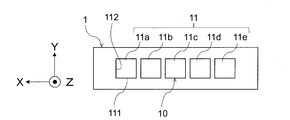
- FIG. 3 is a diagram showing the configuration of the light source unit 1 shown in FIGS. 1 and 2.
- FIG. 3 is a view of the light source unit 1 shown in FIGS. 1 and 2 as viewed from the + Z axis side.
- the light source unit 1 may include a plurality of light emitting elements 10.
- the light emitting element 10 is a solid-state light source.
- a solid light source is a directional light source.
- the solid light source is, for example, a semiconductor light source.
- the light emitting element 10 is a light emitting diode.
- the solid-state light source may be an organic electroluminescence light source, or may be a light source that emits light by irradiating a phosphor coated on a plane with excitation light.
- the light source unit 1 includes a plurality of light emitting surfaces 11.
- the plurality of light emitting surfaces 11 include N light emitting surfaces 11 arranged in a predetermined arrangement direction. In FIG. 3, N is 5. N may be an integer of 2 or more.
- the arrangement direction of the plurality of light emitting surfaces 11 is the X-axis direction.
- the plurality of light emitting surfaces 11 arranged in the X-axis direction are also referred to as 11a, 11b, 11c, 11d, and 11e. Further, in the example shown in FIG. 3, the plurality of light emitting surfaces 11 are linearly arranged in a row.
- the number of light emitting surfaces 11 included in the light source unit 1 may be one.
- the light source unit 1 may be provided with a configuration for adjusting light distribution, such as a movable light-shielding plate (not shown).
- the light emitting surface 11 has a rectangular shape, for example.
- the length of the side 111 extending in the X-axis direction is equal to the length of the side 112 extending in the Y-axis direction. That is, in FIG. 3, the light emitting surface 11 has a square shape.
- the light emitting surface 11 is not limited to a square shape and a rectangular shape.
- the first optical unit 2 is located on the emission direction side (in this example, the + Z axis side) where the light source unit 1 emits the light L0.
- Light L0 is incident on the first optical unit 2.
- the first optical unit 2 changes the light distribution pattern of the incident light L0.
- the first optical unit 2 is, for example, a light distribution changing lens 20.
- the first optical unit 2 may be configured by a reflection mirror.
- the light distribution changing lens 20 is, for example, a lens having a positive power.
- the light distribution changing lens 20 is, for example, a convex lens. However, a concave lens may be used as the light distribution changing lens 20.
- the light distribution changing lens 20 is made of, for example, a transparent resin or the like. In FIGS. 1 and 2, the light distribution changing lens 20 is composed of one lens.
- the light distribution changing lens 20 may be a lens group composed of a plurality of lenses.
- the optical axis of the light source unit 1 is indicated by C1.
- the optical axis of the light distribution changing lens 20 is indicated by C2.
- the optical axis C1 and the optical axis C2 are located on the same straight line, for example. That is, the optical axis C1 and the optical axis C2 coincide with each other.
- the optical axis C1 of the light source unit 1 and the optical axis C2 of the light distribution changing lens 20 do not necessarily have to be located on the same straight line, and the light source unit 1 is at least at a position on the Z axis of the light distribution changing lens 20.
- the light distribution changing lens 20 may have a rotationally asymmetrical shape.
- An example of the light distribution changing lens 20 will be described later with reference to FIGS. 10 (A) and 10 (B) and FIGS. 11 (A) and 11 (B).
- the light L0 which is the first light emitted from the light distribution changing lens 20
- the light L1 travels in the + Z axis direction, passes through the beam splitter 50, and then enters the projection lens 30.
- the second optical unit 3 projects the light distribution pattern of the light L1 formed by the light distribution changing lens 20 in a predetermined projection direction (that is, the + Z axis direction) (hereinafter, also referred to as “projection”).
- the second optical unit 3 is, for example, a projection lens 30.
- the second optical unit 3 may be composed of a reflection mirror or a combination of a reflection mirror and a lens.
- the projection lens 30 is arranged on the + Z axis side of the light source unit 1 and the light distribution changing lens 20. In the Z-axis direction, the distance from the light source unit 1 to the projection lens 30 is, for example, 50 mm or less.
- the light L1 incident on the projection lens 30 passes through the projection lens 30 and is emitted toward a predetermined irradiation region in front of the projection lens 30.
- the "predetermined irradiation region” may be a predetermined region on the irradiation surface 90 arranged on the + Z axis side (projection direction side) of the projection lens 30.
- the irradiation surface 90 is a virtual projection surface on which the light distribution pattern of the light L1 changed by the light distribution changing lens 20 is projected.
- the position where the irradiation surface 90 is arranged is the position where the illuminance or the luminous intensity of the headlight device 100 is measured.
- the position for measuring the illuminance or the luminous intensity of the headlight device is predetermined in the road traffic regulations and the like.
- the measurement position of the luminous intensity of the headlight device defined by UNECE is a position 25 m away from the light source of the headlight device, and the luminous intensity measured by JIS (Japanese Industrial Standards).
- the irradiation surface 90 is arranged at a position 25 m away from the light source unit 1 of the headlight device 100 in the + Z axis direction.
- the light distribution pattern of the light L1 projected on the irradiation surface 90 is referred to as D.
- the projection lens 30 projects the light distribution pattern D of the light L1 onto the irradiation surface 90.
- the projection lens 30 is, for example, a lens having a positive power.
- the projection lens 30 is composed of one lens.
- the projection lens 30 may be a lens group composed of a plurality of lenses. However, when the projection lens 30 is a lens group, the light utilization efficiency decreases as the number of lenses increases. Therefore, it is desirable that the projection lens 30 is composed of one or two lenses.
- the projection lens 30 is made of, for example, a transparent resin or the like.
- the optical axis of the projection lens 30 is indicated by C3.
- the projection lens 30 may have a rotationally symmetric shape with the optical axis C3 as the rotation axis.
- the optical axis C1 and the optical axis C3 of the light source unit 1 are located on the same straight line. That is, the optical axis C1 and the optical axis C3 coincide with each other.
- the optical axis C2 and the optical axis C3 of the light distribution changing lens 20 are located on the same straight line. That is, the optical axis C2 and the optical axis C3 coincide with each other.
- the incident light L2 traveling in the direction opposite to the projection direction ( ⁇ Z axis direction) is incident on the projection lens 30.
- the incident light L2 passes through the projection lens 30, is reflected by the beam splitter 50, and then enters the light receiving unit 4 as light L3.
- the light receiving unit 4 is arranged between the light distribution changing lens 20 and the projection lens 30 in the Z-axis direction.
- the light receiving unit 4 is a photodetector unit that detects light L3, which is the second light emitted from a predetermined light receiving region in front of the light receiving unit 4 and incident through the projection lens 30.
- the light L3 is the detection light detected by the light receiving unit 4.
- the "predetermined light receiving region” may be a predetermined region existing on the + Z axis side (projection direction side) of the projection lens 30.
- the predetermined light receiving region may be, for example, a region including at least the above-mentioned “predetermined irradiation region”.
- the light L3 may be the light emitted from the object.
- the light L3 may be light emitted from the headlight of the oncoming vehicle.
- the light L3 may be the light emitted from the tail light of the preceding vehicle.
- the light L3 may be the light L1 reflected by the object. ..
- the object to be the light emitting point of the light L3 can be an arbitrary object (road surface, oncoming vehicle, preceding vehicle, pedestrian, etc.) located on the + Z axis side of the projection lens 30.
- the light L3 is limited to the light emitted from another object (that is, the light L3 to the light L1). It is also possible to exclude the reflected light of.
- FIG. 4 is a diagram showing the configuration of the light receiving unit 4 shown in FIGS. 1 and 2.
- FIG. 4 is a view of the light receiving portion 4 shown in FIGS. 1 and 2 as viewed from the ⁇ Y axis side.
- the light receiving unit 4 may include a plurality of light receiving elements 40.
- the light receiving element 40 is, for example, a semiconductor element that converts the energy of the received light into an electric signal.
- the light receiving element 40 is, for example, a photodiode, a CCD (Charge Coupled Device) image sensor, a CMOS (Complementary Metal Oxide Semiconductor) image sensor, or the like.
- the light receiving unit 4 may be a line sensor including a plurality of light receiving elements 40.
- the surface of the light receiving element 40 on the ⁇ Y axis side is referred to as a light receiving surface 41.
- the light receiving unit 4 includes a plurality of light receiving surfaces 41 arranged in the X-axis direction.
- the plurality of light receiving surfaces 41 arranged in the X-axis direction are also referred to as 41a, 41b, 41c, 41d, 41e.
- the plurality of light receiving surfaces 41 include M light receiving surfaces 41 arranged in a direction corresponding to the arrangement direction of the plurality of light emitting surfaces 11.
- the "direction corresponding to the arrangement direction of the plurality of light emitting surfaces 11" is a direction parallel to the arrangement direction of the plurality of light emitting surfaces 11 and a direction inclined rather than parallel to the arrangement direction of the plurality of light emitting surfaces 11. It means to include. In FIG.
- the plurality of light receiving surfaces 41 are arranged in the X-axis direction parallel to the arrangement direction of the plurality of light emitting surfaces 11. Further, in FIG. 4, M is 5.
- the number M of the plurality of light receiving surfaces 41 is equal to the number N of the plurality of light emitting surfaces 11 shown in FIG. Therefore, in the first embodiment, the plurality of light receiving surfaces 41 and the plurality of light emitting surfaces 11 have a one-to-one correspondence. It is desirable that M is an integer of 2 or more.
- the number of light receiving surfaces 41 included in the light receiving unit 4 may be one.
- a plurality of light receiving surfaces 41 may be linearly arranged in a row.
- the light receiving surface 41 has, for example, a rectangular shape.
- the side 412 extending in the Z-axis direction is longer than the side 411 extending in the X-axis direction. That is, the light receiving surface 41 has a rectangular shape that is long in the Z-axis direction. This is because a margin is provided in the vertical direction (that is, the Z-axis direction) of the light receiving surface 41 so that a moving vehicle such as a vehicle in front or a pedestrian can be accurately detected.
- the light receiving surface 41 is not limited to a rectangular shape and a rectangular shape.
- the third optical unit 5 is an optical member arranged between the light distribution changing lens 20 and the projection lens 30 in the Z-axis direction.
- the third optical unit 5 is, for example, a beam splitter 50.
- the third optical unit 5 may be configured by a dichroic mirror.
- the beam splitter 50 emits the incident light L1 in the + Z axis direction.
- the light source unit 1 is arranged on the ⁇ Z axis side of the beam splitter 50.
- the beam splitter 50 emits the light L1 incident from the ⁇ Z axis side as illumination light in the + Z axis direction.
- the "+ Z-axis direction" is also referred to as the "emission direction”.
- the light receiving unit 4 is arranged on the + Y-axis side of the beam splitter 50.
- the beam splitter 50 guides the incident light L2 incident through the projection lens 30 to the light receiving unit 4. Specifically, the beam splitter 50 emits the incident light L2 traveling in the direction opposite to the emission direction of the light L1 (that is, the ⁇ Z axis direction) as the light L3 toward the light receiving unit 4. In the first embodiment, the beam splitter 50 transmits the light L1 and emits the light L1 in the exit direction, reflects the incident light L2 and emits the light L3 toward the light receiving unit 4.
- the beam splitter 50 has a property of transmitting light L1, that is, light transmission. Further, the beam splitter 50 includes a surface 50a that reflects the incident light L2. The angle of the surface 50a with respect to the optical axis C1 is 45 degrees. However, this angle is not limited to 45 degrees. When the incident light L2 is reflected by the surface 50a, the incident light L2 travels in the + Y-axis direction as the light L3 toward the light receiving unit 4.
- the surface 50a reflects the incident light L2 by Fresnel reflection.
- the surface 50a may be a surface coated with a half mirror or the like.
- the surface 50a is a surface that reflects the incident light L2 by Fresnel reflection, the light transmission is improved as compared with the case where the surface 50a is a surface coated with a half mirror. Therefore, the light L1 is efficiently incident on the projection lens 30.
- the fourth optical unit 6 is arranged between the beam splitter 50 and the light receiving unit 4 in the Y-axis direction.
- Light L3 is incident on the fourth optical unit 6.
- the fourth optical unit 6 collects the incident light L3 and directs it toward the light receiving unit 4.
- the fourth optical unit 6 is, for example, a condenser lens 60.
- the fourth optical unit 6 may be configured by a reflection mirror.
- the condenser lens 60 is, for example, a lens having a positive power.
- the condenser lens 60 is, for example, a convex lens. Since the condenser lens 60 and the projection lens 30 have positive power, the light L3 incident on the condenser lens 60 via the projection lens 30 and the beam splitter 50 is imaged on the light receiving unit 4.
- the condenser lens 60 is a lens for forming an image of the scenery in front of the vehicle equipped with the headlight device 100 on the light receiving unit 4. Therefore, the condenser lens 60 has a power different from that of the light distribution changing lens 20.
- the optical axis of the light receiving unit 4 is indicated by C4
- the optical axis of the condenser lens 60 is indicated by C6.
- the optical axis C4 and the optical axis C6 are located on the same straight line. That is, the optical axis C4 and the optical axis C6 coincide with each other.
- the condenser lens 60 may have a rotationally symmetric shape with the optical axis C6 as the rotation axis.
- the optical axis C6 coincides with the optical axis C3 of the projection lens 30 on the + Z axis side of the beam splitter 50.
- the light source unit 1, the light distribution changing lens 20, and the projection lens 30 of the headlight device 100 irradiate the light L1 as illumination light toward a predetermined irradiation area in front of the vehicle equipped with the headlight device 100. It constitutes an optical system 110. Further, the projection lens 30, the condenser lens 60, and the light receiving unit 4 of the headlight device 100 constitute an imaging optical system 120 that images the front of the vehicle equipped with the headlight device 100. That is, the projection optical system 110 and the imaging optical system 120 share the projection lens 30 which is the second optical unit 3.
- the optical axis C6 of the condenser lens 60 constituting the imaging optical system 120 coincides with the optical axis C3 of the projection lens 30 constituting the projection optical system 110 on the + Z axis side of the beam splitter 50. .. That is, a part of the optical axis of the projection optical system 110 and a part of the optical axis of the imaging optical system 120 coincide with each other.
- the projection optical system 110 and the imaging optical system 120 a part of the optical axis is common and the projection lens 30 is shared, so that the irradiation range and the headlight of the light L1 emitted from the headlight device 100 are shared. It becomes easy to match the incident range of the incident light L2 incident on the lighting device 100, and the field of view for detecting the vehicle located in the irradiation direction of the light L1 and the irradiation range of the light distribution pattern of the light L1 are deviated. Can be suppressed.
- the headlight device 100 described above has a configuration in which the light source unit 1 is arranged on the ⁇ Z axis side of the beam splitter 50 and the light receiving unit 4 is arranged on the + Y axis side of the beam splitter 50. Therefore, the beam splitter 50 is an optical member that transmits light L1 and emits light in the + Z-axis direction, and reflects incident light L2 and directs it toward the light receiving unit 4.
- the beam splitter 500 is another optical member. You may.
- the light receiving unit 4 may be arranged on the ⁇ Z axis side of the beam splitter 50, and the light source unit 1 may be arranged on the + Y axis side of the beam splitter 50. That is, the beam splitter 50 may be an optical member that reflects the light L1 and emits it in the + Z-axis direction, and transmits the incident light L2 to the light receiving unit 4.
- FIG. 5 is a diagram showing an example of a plurality of light distribution patterns Da to De corresponding to each of the plurality of light emitting surfaces 11a to 11e shown in FIG.
- FIG. 6A is a diagram showing an example of the light distribution pattern D of the light L1.
- the plurality of light distribution patterns Da to De shown in FIG. 5 are light distribution patterns of a plurality of light L0 emitted from each of the plurality of light emitting surfaces 11a to 11e.
- the light distribution pattern Da is a light distribution pattern of light emitted from the light emitting surface 11a.
- the plurality of light distribution patterns Da to De before being incident on the light distribution changing lens 20 are, for example, square shapes similar to the shapes of the plurality of light emitting surfaces 11a to 11e.
- a rectangular shape also referred to as "molding”
- the light distribution pattern D of the light L1 is formed and projected onto the irradiation surface 90.
- FIG. 5 shows the simulation results before the plurality of light distribution patterns Da to De are combined by the light distribution changing lens 20.
- FIG. 6A is a diagram showing a simulation result of a light distribution pattern D projected on the irradiation surface 90 when all of the plurality of light emitting surfaces 11a to 11e shown in FIG. 3 are lit.
- the plurality of light emitting surfaces 11 shown in FIG. 3 and the plurality of light receiving surfaces 41 shown in FIG. 4 correspond to each other.
- a plurality of regions in which a plurality of light distribution patterns Da to De are projected on the irradiation surface 90 and a plurality of detection regions of the light L3 detected by the plurality of light receiving surfaces 41 correspond to each other. That is, the light L3 (shown in FIG. 1) incident on the plurality of light receiving surfaces 41 has a plurality of regions in which the plurality of light distribution patterns Da to De (shown in FIG. 6A) are projected onto the irradiation surface 90. Emit from.
- the light receiving surfaces 41a, 41b, 41c, 41d, 41e are incidents emitted from positions where the light distribution patterns Da, Db, Dc, Dd, and De overlap with the projected positions.
- Each light that is, a part of the incident light L2 is detected.
- Each of the plurality of light receiving surfaces 41a to 41e outputs a detection result (for example, a detection signal corresponding to the detected light) to the control unit 7 shown in FIGS. 1 and 2.
- the detection result may be, for example, a signal indicating the amount of received light, or a flag indicating whether or not the amount of received light received is received by a predetermined threshold value T1 or more.
- the detection result is only the above example.
- control unit 7 turns off the light emitting surface 11 corresponding to the light receiving surface 41 that has detected light having a light receiving amount equal to or higher than a predetermined threshold value T1 among the plurality of light emitting surfaces 11, and turns off the other light emitting surfaces 11. Controls the lighting.
- FIG. 6B is a diagram showing another example of the light distribution pattern D of the light L1.
- FIG. 6B is a simulation result of the light distribution pattern D projected on the irradiation surface 90 when the four light emitting surfaces 11a, 11b, 11d, and 11e shown in FIG. 3 are lit. That is, in FIG. 6B, the light emitting surface 11c is turned off.
- the light distribution pattern D shown in FIG. 6B has a first light distribution pattern D1 and a second light distribution pattern D2.
- the first light distribution pattern D1 is a light distribution pattern formed by synthesizing the light distribution pattern Da and the light distribution pattern Db.
- the second light distribution pattern D2 is a light distribution pattern formed by synthesizing the light distribution pattern Dd and the light distribution pattern De. That is, in FIG. 6B, the light distribution pattern Dc shown in FIG. 6A is not projected on the irradiation surface 90.
- FIG. 7 is a functional block diagram showing the configuration of the headlight device 100.
- the headlight device 100 may have a control unit 7 connected to a light source unit 1 and a light receiving unit 4.
- the control unit 7 causes the light source unit 1 to adjust the light distribution pattern of the light L1 based on the detection signal corresponding to the light L3 detected by the light receiving unit 4.
- the detection signal output from the light receiving unit 4 is a signal corresponding to the amount of light received by the light L3 detected by the light receiving unit 4.
- the control unit 7 controls the light emission of the plurality of light emitting surfaces 11 based on the signals corresponding to the light receiving amounts of the light L3 detected on each of the plurality of light receiving surfaces 41, thereby providing the light source unit 1 with a light distribution pattern. Let it be adjusted.
- the light source unit 1 includes a drive circuit (not shown) as a light source drive unit that drives the plurality of light emitting surfaces 11 shown in FIG. For example, when each of the plurality of light emitting surfaces 11 shown in FIG. 3 is turned on and off, the light source unit 1 emits light L0, which is the first light.
- a unit capable of controlling the amount of light emission (including turning on and off) independently of each other may be referred to as a "control unit".
- a light emitting surface 11 and a light emitting element 10 corresponding thereto are illustrated.
- the control unit and the light emitting surface 11 do not necessarily have to coincide with each other.
- a plurality of control units it is possible for a plurality of control units to share one optical surface. Even when the boundary of such a light emitting surface is not clear, when a plurality of units capable of independently controlling the amount of light emitted are provided, it is considered that the plurality of light emitting surfaces 11 are provided. In such a case, the expression "plurality of light emitting surfaces 11" may be read as "a plurality of control units that emit light by one or more light emitting surfaces included in the light source unit 1."
- a unit capable of detecting the amount of light received (including determining the presence or absence of light reception) independently of each other may be referred to as a "detection unit".
- a detection unit a light receiving surface 41 and a light receiving element 40 corresponding thereto are illustrated as shown in FIG. 4 described later.
- the detection unit and the light receiving surface 41 do not necessarily have to match.
- the expression "plurality of light receiving surfaces 41" may be read as "a plurality of detection units that receive light from one or more light receiving surfaces included in the light receiving unit 4."
- the control unit 7 causes the light source unit 1 to adjust the light distribution pattern by controlling to change the light emission amount of each of the plurality of light emitting surfaces 11.
- the control for changing the light emission amount of each of the plurality of light emitting surfaces 11 is not only the control for continuously or stepwise changing the light emission amount of each of the plurality of light emitting surfaces 11, but also the control of the plurality of light emitting surfaces 11. It also includes control to turn on and off each. In the following description, a control in which the control unit 7 turns on and off each of the plurality of light emitting surfaces 11 will be described as an example.
- the control unit 7 includes a threshold value determination unit 71 and a light source control unit 72.
- a detection signal output from the light receiving unit 4 is input to the threshold value determination unit 71.
- the detection signal output from the light receiving unit 4 includes a plurality of signals output from the plurality of light receiving surfaces 41 (shown in FIG. 4) corresponding to the light L3.
- the threshold value determination unit 71 determines whether or not the intensity of the light L3 detected by the light receiving unit 4 is equal to or higher than a predetermined threshold value based on a plurality of signals output from the plurality of light receiving surfaces 41.
- the threshold value is set based on the configuration of the optical system of the headlight device 100, the specifications of the light receiving unit 4, and the like.
- the threshold value is set based on, for example, the amount of light emitted from another vehicle existing at a predetermined distance (for example, 100 m) in the + Z axis direction from the headlight device 100.
- the threshold value determination unit 71 determines whether or not the intensity of the light L3 detected by the light receiving unit 4 is equal to or greater than the threshold value during the extinguishing time when the light source unit 1 is off. Further, the threshold value determination unit 71 determines whether or not the intensity of the light L3 detected on each of the plurality of light receiving surfaces 41 is equal to or greater than the threshold value.
- the threshold value determination unit 71 determines that the intensity of the light L3 detected on at least one light receiving surface 41 among the plurality of light receiving surfaces 41 is equal to or higher than the threshold value, the threshold value determination unit 71 outputs a signal indicating the determination result to the light source control unit 72. ..
- the light source control unit 72 controls to turn on and off each of the plurality of light emitting surfaces 11 shown in FIG. 3 based on the signal output from the threshold value determination unit 71. Specifically, the light source control unit 72 turns off the light emitting surface 11 corresponding to the light receiving surface 41 on which the light L3 having an intensity equal to or higher than a predetermined threshold value is incident among the plurality of light emitting surfaces 11, and other The light emitting surface 11 of the above is controlled to be turned on.
- the light source control unit 72 controls the light source unit 1 so that the light source unit 1 lights up for a predetermined lighting time and periodically repeats the operation of turning off the light source unit 1 for a lighting time shorter than the lighting time.
- control unit 7 does not have to have the threshold value determination unit 71.
- control unit 7 may perform control to continuously reduce the light emission amount of the light source unit 1 or control to turn off the light source unit 1 based on the light reception amount of the light L3 detected by the light receiving unit 4. Good.
- the control unit 7 is, for example, a control circuit composed of a semiconductor integrated circuit.
- the control unit 7 may be configured by a processor that executes a program stored in the memory.
- FIG. 8 is a flowchart showing the control contents of the control unit 7.
- a method of controlling the light emission of the plurality of light emitting surfaces 11 (shown in FIG. 3) by the control unit 7 will be described with reference to the flowchart shown in FIG.
- a loop process is performed in which the processes from steps S1 to S4 are repeated.
- step S1 it is determined whether or not each of the plurality of light receiving surfaces 41 has received light (step S1).
- step S1 when it is determined that each of the plurality of light receiving surfaces 41 does not receive the light L3, that is, when there is no preceding vehicle, oncoming vehicle, or the like in front of the light receiving surface 41, the control unit 7 emits light. Control is performed to turn on all of the surface 11 (step S2). At this time, the light distribution pattern D shown in FIG. 6A is projected onto the irradiation surface 90.
- step S1 when it is determined that at least one light receiving surface 41 among the plurality of light receiving surfaces 41 has received the light L3, that is, when a preceding vehicle or an oncoming vehicle exists in front of the light receiving surface 41, the light receiving surface 41 It is determined whether or not the received amount of the light L3 detected in step 2 is equal to or greater than the threshold value (step S3). If it is determined in step S3 that the amount of received light is less than the threshold value, the process returns to step S1.
- step S3 When it is determined in step S3 that the light receiving amount is equal to or greater than the threshold value, the control unit 7 detects the light receiving surface 41 that has detected the light L3 having the light receiving amount equal to or greater than the threshold value among the plurality of light emitting surfaces 11. Control is performed to turn off 11 (step S4). For example, when it is determined that the light receiving amount of the light L3 detected on the light receiving surface 41c is equal to or more than the threshold value among the plurality of light receiving surfaces 41a to 41e shown in FIG. 4, the plurality of light emitting surfaces 11a to 11a shown in FIG.
- the light emitting surface 11c corresponding to the light receiving surface 41c is turned off, and the other light emitting surfaces 11a, 11b, 11d, 11e are continuously turned on.
- the light distribution pattern D shown in FIG. 6B is projected onto the irradiation surface 90. In this way, the light distribution pattern D is controlled based on the detection result in the light receiving unit 4.
- the control unit 7 may perform control for adjusting the light distribution pattern when a predetermined condition is satisfied.
- the threshold value determination unit 71 determines whether the number of times the intensity of the light L3 incident on the light receiving unit 4 becomes equal to or higher than a predetermined threshold value becomes equal to or higher than a predetermined reference number within a predetermined time. It may be determined whether or not.
- the "predetermined time” is set to a time of 1 second or less. This is because if the predetermined time is too long, the vehicle equipped with the headlight device 100 is too close to the distance of another vehicle (for example, an oncoming vehicle) and the light distribution pattern cannot be changed appropriately.
- FIG. 9 shows one of the plurality of light receiving surfaces 41a shown in FIG. 4 and one of the plurality of light emitting surfaces 11 shown in FIG. 3 in the headlight device 100 according to the first embodiment. It is a figure which shows the irradiation region R20 of the light emitted from the light emitting surface 11a.
- the light receiving surface is used to explain the correspondence between the light receiving surface and the irradiation region of the light L1.
- the irradiation region R20 is superimposed on the above.
- X is used as a new coordinate system in order to facilitate understanding of the description of the light receiving portion.
- 1 Y 1 Z 1 Cartesian coordinate system is used.
- the X 1 Y 1 Z 1 Cartesian coordinate system is a coordinate system in which the XYZ Cartesian coordinate system is viewed from the ⁇ Y axis side.
- X 1 axis is the same as the X-axis.
- Z 1 axis is parallel to the Y axis.
- the light receiving region of one of the light receiving surfaces 41 shown in FIG. 4 is referred to as R10.
- the irradiation region of the light L1 emitted from one of the plurality of light emitting surfaces 11 shown in FIG. 3 is referred to as R20.
- the irradiation region R20 includes a first irradiation region R21 which is a central region of the irradiation region R20 and a second irradiation region R22 which is an annular region outside the first irradiation region R21.
- the first irradiation region R21 is an irradiation region to which light having a predetermined threshold value T2 or more (that is, light intensity) is irradiated.
- the second irradiation region R22 is an irradiation region to which light having a light amount (that is, light intensity) less than the threshold value T2 is irradiated.
- both the first irradiation region R21 and the second irradiation region R22 have an elliptical shape that is long in the Y-axis direction.
- Length A of the Z 1 axial sides of the light receiving surface 41a is greater than the major diameter C match or major axis C of the first irradiation region R21 of the elliptical shape.
- the light receiving region R10 of the light receiving surface 41a has a first light receiving region R11 and a second light receiving region R12.
- the first light receiving region R11 is a region corresponding to the irradiation region R20.
- the first light receiving region R11 is a region for detecting light L3 (shown in FIG. 1) emitted from a region overlapping the irradiation region R20.
- the second light receiving region R12 is arranged at a position adjacent to the first light receiving region R11 in the Z uniaxial direction. As shown in FIG. 9, the light receiving region R10 may have two second light receiving regions R12. The light receiving region R10 may have one second light receiving region R12. By receiving region R10 has a second light receiving region R12, the size of the light receiving region R10, in Z 1 axial direction, greater than the size of the irradiation region R20. In other words, the size of the light receiving surface 41a, in the Z 1 axial direction, greater than the size of the irradiation region R20.
- each of the plurality of light receiving surfaces 41 is larger than the size of the irradiation region R20, but the light receiving surface 41 of at least one of the plurality of light receiving surfaces 41 The size may be larger than the size of the irradiation region R20.
- the second light receiving area R12 is a light receiving area that does not correspond to the irradiation area R20. That is, the light receiving region R10 of the light receiving surface 41a may include a region other than the region corresponding to the irradiation region R20 of the light L1 emitted by the light emitting surface 11a constituting the control unit corresponding to the light receiving surface 41a. Light emitted from the outside of the irradiation region R20 is incident on the second light receiving region R12. Specifically, light emitted from the outside in the vertical direction of the irradiation region R20 is incident on the second light receiving region R12.
- the light receiving unit 4 displays a signal corresponding to the light detected in the first light receiving region R11 and a signal corresponding to the light detected in the second light receiving region R12 in the control unit 7 (FIGS. 1 and 2). ).
- the control unit 7 causes the light source unit 1 (shown in FIGS. 1 and 2) to adjust the light distribution pattern based on the signal corresponding to the light detected in the first light receiving region R11. Further, the control unit 7 uses a light source based on the prediction signal corresponding to the light detected in the second light receiving region R12 before the light L3 having a light amount equal to or higher than the threshold value T1 is incident on the first light receiving region R11.
- the light distribution pattern can be adjusted by the unit 1.
- two second light receiving regions R12 are shown in FIG. 9, the second light receiving region R12 may be one or three or more.
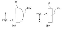
- FIG. 10A is a side view showing an example of the light distribution changing lens 20.
- FIG. 10B is a plan view showing an example of the light distribution changing lens 20.
- the light distribution changing lens 20 is, for example, a toroidal lens.
- the shape of the surface 20a shown in FIG. 10A in the Y-axis direction is a convex curve having a curvature in the Y-axis direction.
- the shape of the surface 20b shown in FIG. 10B in the X-axis direction is a convex curve having a curvature in the X-axis direction.
- the light distribution changing lens 20 has a positive power in the X-axis direction and a positive power in the Y-axis direction.
- the curvature of the surface 20a in the Y-axis direction is larger than the curvature of the surface 20b in the X-axis direction. That is, the positive power in the Y-axis direction is greater than the positive power in the X-axis direction.
- the power is the refractive power.
- the light L0 emitted from the light source unit 1 is incident on the light distribution changing lens 20.
- the plurality of light emitting surfaces 11 shown in FIG. 3 are lit, when the light L0 is incident on the light distribution changing lens 20, the plurality of light distributions are caused by the positive power of the light distribution changing lens 20 in the X-axis direction.
- the patterns Da to De (shown in FIG. 5) are arranged in the X-axis direction on the irradiation surface 90.
- each shape of the plurality of light distribution patterns Da to De becomes a rectangular shape obtained by extending the square shape of the light emitting surface 11 in the Y-axis direction by the positive power of the light distribution changing lens 20 in the Y-axis direction. That is, the light distribution pattern of the light L0 from each light emitting surface 11 before being incident on the light distribution changing lens 20 is rectangular, but the light distribution pattern after passing through the light distribution changing lens 20 is the Y axis. It is a rectangular shape that is long in the direction.
- the plurality of light distribution patterns Da to De projected on the irradiation surface 90 have more blurring at the ends in the Y-axis direction than at the ends in the X-axis direction. That is, the boundary line at the end of each of the light distribution patterns Da to De in the Y-axis direction is unclear.
- the toroidal lens includes a cylindrical lens.
- FIG. 11A is a side view showing a cylindrical lens which is another example of a toroidal lens.
- FIG. 11B is a plan view showing a cylindrical lens which is another example of a toroidal lens.
- the shape of the surface 20a shown in FIG. 11A in the Y-axis direction is a convex curve having a curvature in the Y-axis direction.
- the shape of the surface 20b shown in FIG. 11B in the X-axis direction is a straight line having no curvature in the X-axis direction. Therefore, the light distribution changing lens 20 shown in FIGS.
- the light distribution changing lens 20 may be, for example, a free-form curved lens as long as it can form a light distribution pattern in which the aspect ratio of the light emitting surface 11 of the light source unit 1 is extended in the Y-axis direction.
- the light distribution changing lens 20 may be a free-curved lens having different curvatures in the X-axis direction and the Y-axis direction.
- the above example is an example for forming the light distribution pattern of the light emitted by the light source unit 1 having the plurality of light emitting surfaces 11 arranged in the Z-axis direction into the light distribution shape required for the vehicle lamp. This does not apply when there is one light emitting surface 11 or when a plurality of light emitting surfaces 11 are arranged in the Y-axis direction. Further, as will be described later, this does not apply to the case where the projection lens 30 is used for stretching.
- the lens that changes the light distribution pattern of the light L0 is not limited to the light distribution changing lens 20, and may be the projection lens 30 shown in FIGS. 1 and 2. That is, the projection lens 30 may be a toroidal lens as shown in FIGS. 10A and 10B, 11A and 11B, or a free-form curved lens. Further, even if both the light distribution changing lens 20 and the projection lens 30 are toroidal lenses or free-form surface lenses as shown in FIGS. 10A and 10B and 11A and 11B. Good.
- the curvature of the projection lens 30 is different between the X-axis direction and the Y-axis direction
- the curvature of the condenser lens 60 is different between the X-axis direction and the Y-axis direction
- the X-axis and the Y-axis of the projection lens 30 are different.
- the change in curvature also referred to as “different”
- may be absorbed also referred to as "invalidation”
- the projection lens 30 projects the light distribution pattern D (shown in FIGS. 6A and 6B) changed by the light distribution changing lens 20 onto the irradiation surface 90 shown in FIG.
- F1 the combined focal point of the light distribution changing lens 20 and the projection lens 30 in the X-axis direction
- F2 the focal point on the light receiving portion 4 side
- the composite focal point F1 is a focal point on the ⁇ Z axis side of the light distribution changing lens 20 and the projection lens 30. As shown in FIG.
- the position of the composite focal point F1 in the Z-axis direction overlaps with the position of the light source unit 1 in the Z-axis direction.
- the light distribution changing lens 20 and the projection lens 30 are arranged so that the position of the synthetic focus F1 in the X-axis direction and the position of the light emitting surface 11 of the light source unit 1 overlap in the Z-axis direction.
- the image of the light emitting surface 11 is enlarged and projected on the virtual projection surface in the X-axis direction.
- the position of the combined focus F1 may be a position deviated in the ⁇ Z axis direction from the position of the light emitting surface 11 of the light source unit 1.
- the position of the composite focal point F1 may be ⁇ 2 mm or less with respect to the position of the light emitting surface 11 of the light source unit 1.
- the virtual projection surface 90 may be a surface at a position where the light receiving unit 4 is focused. In that case, the distance on the optical axis of the imaging optical system 120 from the virtual projection surface 90 to the focal point F2 on the light receiving portion 4 side of the condenser lens 60 and the projection optical system 110 from the virtual projection surface 90 to the synthetic focus F1.
- the distance on the optical axis is substantially the same (within an error of 1 mm).
- an appropriate blur can be generated in the X-axis direction, particularly at the boundary of the plurality of light distribution patterns Da to De of the light L0 emitted from the plurality of light emitting surfaces 11. That is, in the light distribution pattern D formed by the plurality of light distribution patterns Da to De, the boundary between the plurality of light distribution patterns Da to De can be blurred, so that the actual projection after these are superimposed is possible. It is possible to suppress uneven illuminance in the light distribution pattern. Therefore, by appropriately setting the positions of the light distribution changing lens 20 and the projection lens 30 in the Z-axis direction, uneven illuminance can be suppressed on the light distribution pattern D projected on the irradiation surface 90.
- the light distribution pattern D is the irradiation surface as shown in FIGS. 6A and 6B. Projected on 90. Specifically, since the light source unit 1 has an imaging relationship with respect to an arbitrary point on the irradiation surface 90, the edge of the light distribution pattern D in at least the vertical direction (that is, the Y-axis direction) is irradiated on the irradiation surface. It can be clearly projected on 90.
- the irradiation surface 90 and the light source unit 1 do not have to be in an imaging relationship.
- the projection optical system 110 and the imaging optical system 120 are irradiated from the headlight device 100 because a part of each other's optical axes is common and the projection lens 30 is shared. It becomes easy to match the irradiation range of the light L1 with the incident range of the incident light L2 incident on the headlight device 100, and the field of view for detecting the vehicle located in the light irradiation direction and the irradiation of the light distribution pattern It is possible to suppress the occurrence of deviation from the range.
- the projection lens 30 is shared in the projection optical system 110 and the imaging optical system 120, the design of the headlight device 100 can be improved.
- the projection optical system 110 includes the light distribution changing lens 20
- the imaging optical system 120 includes the condenser lens 60, so that the shape or curvature of the light distribution changing lens 20 is condensed.
- the shape or curvature of the lens 60 it is possible to control the shape or the amount of blurring of the irradiation region of the light distribution pattern of the light L1 and the imaging region in front of the vehicle.
- the light distribution pattern D projected on the irradiation surface 90 is X.
- the amount of blur can be controlled in the axial direction and the Y-axis direction.
- the edge of the light distribution pattern D in the vertical direction that is, in the Y-axis direction. Can be clearly projected onto the irradiation surface 90, and the edge in the X-axis direction becomes soft.
- the light distribution pattern D can be accurately controlled in the X-axis direction (for example, the irradiation area to be extinguished can be accurately extinguished), and the light L1 including blurring can be irradiated in a wide range in the Y-axis direction. it can.
- the driver of the vehicle equipped with the headlight device 100 notices the existence of another vehicle at an early stage, and then another vehicle. You can recognize that the vehicle gradually appears clearly.
- a plurality of detection units (a plurality of light receiving surfaces 41) and a plurality of control units (a plurality of light emitting surfaces 11 in the first embodiment) have a one-to-one correspondence.
- the control unit 7 controls the light emission of each of the plurality of light emitting surfaces 11 based on the signal output from the light receiving surface 41 corresponding to each of the plurality of light emitting surfaces 11 of the plurality of light receiving surfaces 41. This causes the light source unit 1 to adjust the light distribution pattern. As a result, the target region is appropriately irradiated with the light L1, so that the driver of the vehicle equipped with the headlight device 100 has a good field of view.
- the headlight device 100 when the light distribution pattern of the light L1 is adjusted by turning on and off each of the plurality of light emitting surfaces 11 in the light source unit 1, the light distribution pattern is changed by a simple configuration. Can be adjusted.
- the threshold value determination unit 71 determines whether or not the amount of light L3 received by the plurality of light receiving surfaces 41 is equal to or greater than the threshold value T1 when all of the plurality of light emitting surfaces 11 are turned off. Since the detection signal output from the light receiving unit 4 to the threshold value determination unit 71 does not include the detection signal corresponding to the light L1, the determination accuracy of the threshold value determination unit 71 is improved. Therefore, the control unit 7 can cause the light source unit 1 to accurately adjust the light distribution pattern of the light L1. Further, the control unit 7 makes the lighting time of the light source unit 1 longer than the extinguishing time, so that the irradiation amount of the light L1 can be sufficiently increased.
- the headlamp apparatus 100 the Z 1 axial direction, the light receiving region R10 of the light receiving surface 41, when larger than the irradiation region R20 of the light L1 is light-receiving portion 4, the other in the illumination area of the light L1
- a prediction signal indicating that the vehicle is approaching can be output to the control unit 7.
- the control unit 7 can appropriately switch the light distribution pattern at an early stage by using the prediction signal.
- the headlight device 100 since the image pickup optical system 120 of the headlight device 100 has a light receiving unit 4 including a light receiving element 40, the headlight device is compared with the case where the image pickup optical system has a camera.
- the device 100 can be miniaturized.
- the configuration of the light receiving unit 4 described in the first embodiment may be another configuration.
- the light receiving surface 41 of the light receiving unit 4 of the first embodiment may have another shape.
- FIG. 12A shows a part of the light receiving unit 14 and one of the plurality of light emitting surfaces 11 shown in FIG. 3 in the headlight device according to the modified example of the first embodiment of the present invention. It is a figure which shows the irradiation region R20 of the light emitted from 11a.
- FIG. 12A the same or corresponding components as those shown in FIG. 9 are designated by the same reference numerals as those shown in FIG. 9, and the description thereof will be omitted.
- the length A of the Z 1 axial sides of the light receiving surface 141a of the light receiving portion 14 is the same size as the diameter C of the first irradiation region R21 of the elliptical shape.
- the number M of the plurality of light receiving surfaces 41 may be larger than the number N of the plurality of light emitting surfaces 11.
- the number M of the plurality of light receiving surfaces 41 may be Q times the number N of the plurality of light emitting surfaces 11 (Q is an integer of 2 or more).
- FIG. 12B shows a part of the light receiving unit 24 and one light emitting surface 11a of the plurality of light emitting surfaces 11 shown in FIG. 3 in the headlight device according to another modification of the first embodiment. It is a figure which shows the irradiation area R20 of the light emitted from.
- FIG. 12B the same or corresponding components as those shown in FIG. 9 are designated by the same reference numerals as those shown in FIG. 9, and the description thereof will be omitted.
- FIG. 12B describes an example in which the number M of the plurality of light receiving surfaces 241 is twice the number N of the plurality of light emitting surfaces 11 shown in FIG. As shown in FIG. 12B, two light receiving surfaces 241a and 241b adjacent to each other among the plurality of light receiving surfaces 241 correspond to one irradiation region R20. That is, in FIG. 12B, the two light receiving surfaces 241a and 241b correspond to one light emitting surface 11.
- the configurations of the light receiving units 14 and 24 can be simplified.
- the modified example of the first embodiment is the same as the example shown in FIGS. 1 to 11.
- Embodiment 2 In the first embodiment, an example is described in which all of the plurality of light receiving surfaces 41 included in the light receiving unit 4 correspond to each other with the plurality of light emitting surfaces 11. However, not all of the light receiving surfaces included in the light receiving unit need to correspond to each other with the plurality of light emitting surfaces.
- FIG. 13A is a diagram showing a configuration of a light source unit 21 of the headlight device according to the second embodiment of the present invention.
- FIG. 13B shows the light receiving unit 34 and the plurality of irradiation regions R20 of the light emitted from the plurality of light emitting surfaces 211 shown in FIG. 13A in the headlight device according to the second embodiment. It is a figure.
- the same or corresponding components as those shown in FIG. 9 are designated by the same reference numerals as those shown in FIG. 9, and the description thereof will be omitted.
- the light receiving region formed by the plurality of first light receiving surfaces 342 and the second light receiving surface 343 is R1
- the projection lens 30 shown in FIG. 1 is formed from the plurality of light emitting surfaces 211.
- the irradiation region of the light L1 irradiated through the light L1 is referred to as R2.
- the light source unit 21 includes a plurality of light emitting surfaces 211 (7 in FIG. 13 (A)) arranged in the X-axis direction. Light is emitted from each of the plurality of light emitting surfaces 211.
- the number of the plurality of light receiving surfaces 341 is nine, which is larger than the number of the plurality of light emitting surfaces 311 shown in FIG. 13 (A).
- the plurality of light receiving surfaces 341 include a plurality of first light receiving surfaces 342 and a plurality of second light receiving surfaces 343.
- the plurality of first light receiving surfaces 342 are light receiving surfaces corresponding to the plurality of irradiation regions R20 of the light L1 (shown in FIG. 1). That is, the plurality of first light receiving surfaces 342 correspond to each other with the plurality of light emitting surfaces 211 shown in FIG. 13 (A).
- the second light receiving surface 343 is located adjacent to the outside of the first light receiving surface 342 (on the right side in FIG. 13B) located at the end on the + X 1- axis side of the plurality of first light receiving surfaces 342. (in FIG. 13 (B), left side) and a first inner than the light receiving surface 342 located on the -X 1 shaft side is disposed at a position adjacent to the. Since the light receiving portion 34 includes the second light receiving surface 343, the size of the light receiving region R1 is larger than the size of the irradiation region R2.
- the plurality of second light receiving surfaces 343 are light receiving surfaces that do not correspond to the plurality of irradiation regions R20 of the light L1 (shown in FIG. 1). That is, the plurality of second light receiving surfaces 343 do not correspond to the plurality of light emitting surfaces 211 shown in FIG. 13 (A).
- Light emitted from the outside of the irradiation region of the light L1 is incident on the second light receiving surface 343.
- light emitted from the outside in the left-right direction of the irradiation region R2 of the light L1 is incident on the second light receiving surface 343. That is, light emitted from a region wider than the irradiation region R2 of the light L1 is incident on the second light receiving surface 343 as incident light.
- the signal corresponding to the light detected on the second light receiving surface 343 is a prediction signal that predicts the light that will be incident on the first light receiving surface 342.
- the light receiving unit 34 displays a signal corresponding to the light detected on the first light receiving surface 342 and a signal corresponding to the light detected on the second light receiving surface 343 by the control unit 7 (FIGS. 1 and 2). ).
- the control unit 7 causes the light source unit 21 (shown in FIG. 13A) to adjust the light distribution pattern based on the signal corresponding to the light detected on the first light receiving surface 342.
- the control unit 7 is a light source unit before light having a light amount equal to or higher than the threshold value T1 is incident on the first light receiving surface 342 based on the prediction signal corresponding to the light detected on the second light receiving surface 343. 21 can adjust the light distribution pattern.
- two second light receiving surfaces 343 are shown in FIG.
- the number of the second light receiving surfaces 343 may be one or three or more.
- the light receiving unit 34 has P first light receiving surfaces 342 corresponding to the plurality of control units (in the second embodiment, the plurality of light emitting surfaces 211) and at least one not corresponding to the plurality of control units. It suffices to have a second light receiving surface 343.
- P is an integer of 2 or more.
- the control unit 7 applies a light distribution pattern to the light source unit 21 before light having a light amount equal to or higher than the threshold value T1 is incident on the first light receiving surface 342 based on the prediction signal output from the light receiving unit 34. It can be adjusted. Therefore, in the headlight device according to the second embodiment, the control unit 7 can cause the light source unit 1 to adjust an appropriate light distribution pattern at an early stage.
- the headlight device according to the second embodiment is the same as the headlight device 100 according to the first embodiment.
- Embodiment 3 In the first embodiment, an example in which a plurality of light emitting surfaces 11 are linearly arranged in a row in the light source unit 1 will be described. However, the plurality of light emitting surfaces may be arranged in a matrix of J (J is an integer of 2 or more) in the Y-axis direction and N (N is an integer of 2 or more) in the X-axis direction.
- FIG. 14A is a diagram showing a configuration of a light source unit 31 of the headlight device according to the third embodiment of the present invention.
- FIG. 14B shows the light receiving unit 44 and the plurality of irradiation regions R20 of the light emitted from the plurality of light emitting surfaces 311 shown in FIG. 14A in the headlight device according to the third embodiment. It is a figure.
- the same or corresponding components as those shown in FIG. 9 are designated by the same reference numerals as those shown in FIG. 9, and the description thereof will be omitted.
- the light source unit 31 includes a plurality of light emitting surfaces 311 arranged in a matrix of a plurality of rows and a plurality of columns (2 rows and 7 columns in FIG. 14 (A)).
- the light receiving unit 44 includes a plurality of light receiving surfaces 441.
- One of the plurality of light receiving surfaces 441 is a light receiving surface 441 corresponding to two irradiation regions R20 arranged in the Y-axis direction. That is, one light receiving surface 441 corresponds to two light emitting surfaces 311 arranged in the Y-axis direction among the plurality of light emitting surfaces 311.
- the plurality of light receiving surfaces 441 may correspond one-to-one with the plurality of light emitting surfaces 311. That is, the plurality of light receiving surfaces 441 may be arranged in a matrix of 2 rows and 7 columns.
- the plurality of light emitting surfaces 311 are arranged in a matrix of a plurality of rows and a plurality of columns, it is possible to irradiate the light L1 with a more appropriate light distribution pattern. it can.
- the number of the plurality of light receiving surfaces 441 is smaller than the number of the plurality of light emitting surfaces 311. Therefore, the configuration of the light receiving unit 44 can be simplified.
- the headlight device according to the third embodiment is the same as the headlight device according to the first embodiment.
- Embodiment 4 In the first embodiment, an example of the headlight device 100 including one headlight module 100a has been described. However, the headlight device may include a plurality of headlight modules 100a.
- FIG. 15 is a plan view schematically showing the configuration of the headlight device 400 according to the fourth embodiment of the present invention.
- the headlight device 400 includes a plurality of headlight modules 100a, a housing 401, and a cover 402.
- one headlight module 100a is controlled by one control unit 7, but in FIG. 15, a plurality of headlight modules 100a may be controlled by a common control unit.
- the housing 401 is arranged inside the vehicle body of the vehicle equipped with the headlight device 400.
- the shape of the housing 401 is box-shaped.
- a plurality of (three in FIG. 15) headlight modules 100a are housed inside the housing 401.
- the shape of the housing 401 is not limited to the box shape.
- the housing 401 may be composed of a frame or the like, and a plurality of headlight modules 100a may be fixed to the frame.
- the plurality of headlight modules 100a are arranged in the X-axis direction.
- the arrangement direction of the plurality of headlight modules 100a is not limited to the X-axis direction, and may be another direction.
- the plurality of headlight modules 100a may be arranged in the Y-axis direction.
- the plurality of headlight modules 100a are arranged in a direction inclined with respect to the Y-axis direction, a direction inclined with respect to the Z-axis direction, or a direction inclined with respect to both the Y-axis direction and the Z-axis direction. You may.
- An appropriate arrangement of the plurality of headlight modules 100a can improve the design and function of the headlight device 400.
- the cover 402 is arranged on the + Z axis side of the housing 401.
- the cover 402 is arranged on the surface of the vehicle body and is exposed to the outside of the vehicle body.
- the cover 402 is made of, for example, a transparent material.
- each of the plurality of headlight modules 100a accurately covers the target region (for example, the region excluding the preceding vehicle and the oncoming vehicle) with the light L1. Irradiate. Therefore, the headlight device 400 can more accurately irradiate the target area with the light L1.
- the plurality of headlight modules 100a are protected from wind, rain, dust, etc. by the cover 402.
- the fourth embodiment is the same as the first embodiment.
- a light source unit that emits first light and adjusts the light distribution pattern of the first light
- a light distribution changing lens that changes the light distribution pattern adjusted by the light source unit
- a light receiving unit that detects the incident second light
- An optical member that emits the first light emitted from the light distribution changing lens in a predetermined emission direction, and emits incident light traveling in a direction opposite to the emission direction as the second light toward the light receiving portion.
- a projection lens that emits the first light emitted from the optical member as illumination light in the emission direction.
- a condensing lens that condenses the second light emitted from the optical member and directs it toward the light receiving portion.
- the light source unit has a control unit that adjusts the light distribution pattern based on the intensity of the second light detected by the light receiving unit.
- the light source unit includes a plurality of light emitting surfaces arranged in a predetermined first direction.
- the light receiving unit includes a plurality of light receiving surfaces arranged in a direction corresponding to the first direction. The plurality of light emitting surfaces and the plurality of light receiving surfaces correspond to each other.
- the control unit determines that the intensity of the second light incident on the light receiving surface corresponding to each of the plurality of light emitting surfaces among the plurality of light receiving surfaces is equal to or higher than a predetermined threshold value.
- a headlight device that changes the light distribution pattern by controlling the light emission of each of the plurality of light emitting surfaces.
- the plurality of light emitting surfaces are N light emitting surfaces (N is an integer of 2 or more) arranged in the first direction.
- the plurality of light receiving surfaces are M light receiving surfaces (M is an integer of 2 or more) arranged in a direction corresponding to the first direction.
- ⁇ Appendix 3> The headlight device according to Appendix 1 or 2, wherein the size of the light receiving region formed by the plurality of light receiving surfaces is larger than the size of the first light irradiation region.
- M is Q times or more of N (Q is an integer of 2 or more), and one of the N light emitting surfaces and one of the M light receiving surfaces are adjacent to each other.
- the control unit emits light from each of the N light emitting surfaces based on signals output from the Q light receiving surfaces corresponding to each of the N light emitting surfaces of the M light receiving surfaces.
- the light distribution changing lens has a first positive power in the first direction and is different from the first positive power in a second direction orthogonal to the first direction.
- the headlight device according to any one of Supplementary note 2 to 5, which has a positive power of 2.
- the control unit determines that the number of times the intensity of the second light detected by the light receiving unit becomes equal to or greater than the threshold value exceeds a predetermined reference number within a predetermined time.
- the headlight device according to any one of Supplementary note 1 to 6, wherein the light source unit adjusts the light distribution pattern when the light source unit is used.
- the control unit has the light distribution pattern on the light source unit based on the intensity of the second light detected by the light receiving unit during the extinguishing time when the light source unit is off.
- the headlight device according to any one of Supplementary note 1 to 7, wherein the headlight device is adjusted.
- the control unit controls the light source unit so that the light source unit lights up for a predetermined lighting time and repeats the operation of turning off the light source unit for the extinguishing time shorter than the lighting time.
- the plurality of light emitting surfaces are J in the second direction orthogonal to the first direction (J is an integer of 2 or more) and N in the first direction (N is an integer of 2 or more). ) Are arranged in a matrix, The J light emitting surfaces arranged in the second direction of the plurality of light emitting surfaces correspond to one light receiving surface of the plurality of light receiving surfaces.
- the control unit outputs signals from each of the plurality of light emitting surfaces arranged in a matrix from the one light receiving surface corresponding to the J light emitting surfaces arranged in the second direction.
- the headlight device according to any one of Supplementary note 1 to 9, wherein the light source unit adjusts the light distribution pattern by controlling based on the above.
- the optical member is a beam splitter that transmits the first light and emits it in the emitting direction, reflects the incident light and emits it as the second light toward the light receiving portion.
- the headlight device according to any one of Appendix 1 to 10.
- the optical member is a beam splitter that reflects the first light and emits it in the emission direction, transmits the incident light, and emits as the second light toward the light receiving portion.
- the headlight device according to any one of Appendix 1 to 10.
- a plurality of headlight modules are provided, and each of the plurality of headlight modules has a plurality of headlight modules.
- the light source unit that emits the first light
- a first optical unit that changes the light distribution pattern of the incident first light
- a light receiving unit that detects the incident second light
- a second optical unit that projects the light distribution pattern in a predetermined projection direction and receives incident light traveling in the direction opposite to the projection direction.
- a third optical unit that emits the first light toward the second optical unit and emits the incident light that has passed through the second optical unit as the second light toward the light receiving unit.
- It has a fourth optical unit that collects the second light emitted from the third optical unit and directs it toward the light receiving unit.
- a part of the optical axis of the projection optical system including the light source unit, the first optical unit, and the second optical unit includes the second optical unit, the fourth optical unit, and the light receiving unit. Consistent with part of the optical axis of the imaging optics, including A headlight device in which the light distribution pattern is controlled based on the detection result of the second light in the light receiving unit.
- 1,21,31 Light source unit 2 1st optical unit, 3 2nd optical unit, 4,14,24,34,44 light receiving unit, 5 3rd optical unit, 6 4th optical unit, 7 control Department, 11,211,311 light emitting surface, 20 light distribution changing lens, 41,141a, 241,341,441 light receiving surface, 60 condensing lens, 100,400 headlight device, 110 projection optical system, 120 imaging optical system , L0, L1 first light, L2 incident light, L3 second light.
Landscapes
- Engineering & Computer Science (AREA)
- General Engineering & Computer Science (AREA)
- Mechanical Engineering (AREA)
- Physics & Mathematics (AREA)
- Microelectronics & Electronic Packaging (AREA)
- Optics & Photonics (AREA)
- Lighting Device Outwards From Vehicle And Optical Signal (AREA)
- Arrangement Of Elements, Cooling, Sealing, Or The Like Of Lighting Devices (AREA)
- Non-Portable Lighting Devices Or Systems Thereof (AREA)
Priority Applications (5)
| Application Number | Priority Date | Filing Date | Title |
|---|---|---|---|
| DE112019007897.6T DE112019007897T5 (de) | 2019-11-13 | 2019-11-13 | Scheinwerfervorrichtung |
| PCT/JP2019/044499 WO2021095156A1 (ja) | 2019-11-13 | 2019-11-13 | 前照灯装置 |
| JP2021555688A JP7241908B2 (ja) | 2019-11-13 | 2019-11-13 | 前照灯装置 |
| US17/766,742 US11970108B2 (en) | 2019-11-13 | 2019-11-13 | Headlight device |
| CN201980101879.XA CN114641652B (zh) | 2019-11-13 | 2019-11-13 | 前照灯装置 |
Applications Claiming Priority (1)
| Application Number | Priority Date | Filing Date | Title |
|---|---|---|---|
| PCT/JP2019/044499 WO2021095156A1 (ja) | 2019-11-13 | 2019-11-13 | 前照灯装置 |
Publications (1)
| Publication Number | Publication Date |
|---|---|
| WO2021095156A1 true WO2021095156A1 (ja) | 2021-05-20 |
Family
ID=75911924
Family Applications (1)
| Application Number | Title | Priority Date | Filing Date |
|---|---|---|---|
| PCT/JP2019/044499 Ceased WO2021095156A1 (ja) | 2019-11-13 | 2019-11-13 | 前照灯装置 |
Country Status (5)
| Country | Link |
|---|---|
| US (1) | US11970108B2 (https=) |
| JP (1) | JP7241908B2 (https=) |
| CN (1) | CN114641652B (https=) |
| DE (1) | DE112019007897T5 (https=) |
| WO (1) | WO2021095156A1 (https=) |
Cited By (1)
| Publication number | Priority date | Publication date | Assignee | Title |
|---|---|---|---|---|
| US11933468B2 (en) | 2020-09-16 | 2024-03-19 | Mitsubishi Electric Corporation | Headlight device having optical beam splitter |
Citations (4)
| Publication number | Priority date | Publication date | Assignee | Title |
|---|---|---|---|---|
| WO1998054030A1 (en) * | 1997-05-29 | 1998-12-03 | Räfshult | A lighting device having a controllable lighting pattern |
| WO2013015213A1 (ja) * | 2011-07-28 | 2013-01-31 | 株式会社デンソー | 前照灯配光制御装置及び方法 |
| JP2016039020A (ja) * | 2014-08-07 | 2016-03-22 | 株式会社小糸製作所 | 車両用灯具 |
| JP2018156862A (ja) * | 2017-03-17 | 2018-10-04 | トヨタ自動車株式会社 | 車両用前照灯装置 |
Family Cites Families (7)
| Publication number | Priority date | Publication date | Assignee | Title |
|---|---|---|---|---|
| JP2010217241A (ja) | 2009-03-13 | 2010-09-30 | Genesis Technology Co Ltd | 画像表示システム |
| JP6001238B2 (ja) | 2011-02-14 | 2016-10-05 | 株式会社小糸製作所 | 車両用前照灯の配光制御装置 |
| JP2013191478A (ja) | 2012-03-15 | 2013-09-26 | Koito Mfg Co Ltd | 車両用の前照灯装置 |
| EP3179158A4 (en) | 2014-08-07 | 2018-03-21 | Koito Manufacturing Co., Ltd. | Lamp for vehicles |
| US9855887B1 (en) * | 2015-07-28 | 2018-01-02 | Apple Inc. | Dynamic control of projected light relative to a scene |
| JP2018024374A (ja) | 2016-08-12 | 2018-02-15 | アイシン精機株式会社 | 車両用投影装置 |
| JP6727326B2 (ja) * | 2016-11-17 | 2020-07-22 | 三菱電機株式会社 | 発光装置、電子機器、照明装置および車両用前照灯 |
-
2019
- 2019-11-13 CN CN201980101879.XA patent/CN114641652B/zh active Active
- 2019-11-13 US US17/766,742 patent/US11970108B2/en active Active
- 2019-11-13 DE DE112019007897.6T patent/DE112019007897T5/de active Pending
- 2019-11-13 WO PCT/JP2019/044499 patent/WO2021095156A1/ja not_active Ceased
- 2019-11-13 JP JP2021555688A patent/JP7241908B2/ja active Active
Patent Citations (4)
| Publication number | Priority date | Publication date | Assignee | Title |
|---|---|---|---|---|
| WO1998054030A1 (en) * | 1997-05-29 | 1998-12-03 | Räfshult | A lighting device having a controllable lighting pattern |
| WO2013015213A1 (ja) * | 2011-07-28 | 2013-01-31 | 株式会社デンソー | 前照灯配光制御装置及び方法 |
| JP2016039020A (ja) * | 2014-08-07 | 2016-03-22 | 株式会社小糸製作所 | 車両用灯具 |
| JP2018156862A (ja) * | 2017-03-17 | 2018-10-04 | トヨタ自動車株式会社 | 車両用前照灯装置 |
Cited By (1)
| Publication number | Priority date | Publication date | Assignee | Title |
|---|---|---|---|---|
| US11933468B2 (en) | 2020-09-16 | 2024-03-19 | Mitsubishi Electric Corporation | Headlight device having optical beam splitter |
Also Published As
| Publication number | Publication date |
|---|---|
| JPWO2021095156A1 (https=) | 2021-05-20 |
| CN114641652B (zh) | 2025-05-13 |
| CN114641652A (zh) | 2022-06-17 |
| US11970108B2 (en) | 2024-04-30 |
| JP7241908B2 (ja) | 2023-03-17 |
| DE112019007897T5 (de) | 2022-09-15 |
| US20240083345A1 (en) | 2024-03-14 |
Similar Documents
| Publication | Publication Date | Title |
|---|---|---|
| JP6542446B2 (ja) | 前照灯モジュール | |
| US10107469B2 (en) | Vehicular lamp, vehicular lamp control system, and vehicle including the same | |
| JP6709655B2 (ja) | 車両用灯具、および当該車両用灯具を備えた車両 | |
| JP6045719B2 (ja) | 前照灯モジュール及び前照灯装置 | |
| CN104279485B (zh) | 车辆用灯具 | |
| CN112443806B (zh) | 前照灯模块 | |
| JP6324635B2 (ja) | 前照灯モジュール及び前照灯装置 | |
| JPWO2015033764A1 (ja) | 車両用灯具 | |
| JP2017174736A (ja) | 車両用灯具、および当該車両用灯具を備えた車両 | |
| WO2015076203A1 (ja) | 前照灯モジュール及び前照灯装置 | |
| JP7053227B2 (ja) | 光照射装置及び車両用灯具 | |
| JP5043597B2 (ja) | ダイレクトプロジェクション型照明用灯具 | |
| JP6170393B2 (ja) | 車両用灯具 | |
| TWI388773B (zh) | 光源共用光學系統 | |
| WO2021095156A1 (ja) | 前照灯装置 | |
| JP7305057B2 (ja) | 前照灯装置 | |
| KR20190063984A (ko) | 차량용 램프 |
Legal Events
| Date | Code | Title | Description |
|---|---|---|---|
| 121 | Ep: the epo has been informed by wipo that ep was designated in this application |
Ref document number: 19952840 Country of ref document: EP Kind code of ref document: A1 |
|
| ENP | Entry into the national phase |
Ref document number: 2021555688 Country of ref document: JP Kind code of ref document: A |
|
| WWE | Wipo information: entry into national phase |
Ref document number: 17766742 Country of ref document: US |
|
| 122 | Ep: pct application non-entry in european phase |
Ref document number: 19952840 Country of ref document: EP Kind code of ref document: A1 |
|
| WWG | Wipo information: grant in national office |
Ref document number: 201980101879.X Country of ref document: CN |