WO2021090956A1 - ヘッドアップディスプレイ、ヘッドアップディスプレイシステム及び移動体 - Google Patents
ヘッドアップディスプレイ、ヘッドアップディスプレイシステム及び移動体 Download PDFInfo
- Publication number
- WO2021090956A1 WO2021090956A1 PCT/JP2020/041872 JP2020041872W WO2021090956A1 WO 2021090956 A1 WO2021090956 A1 WO 2021090956A1 JP 2020041872 W JP2020041872 W JP 2020041872W WO 2021090956 A1 WO2021090956 A1 WO 2021090956A1
- Authority
- WO
- WIPO (PCT)
- Prior art keywords
- image
- distance
- user
- display
- display panel
- Prior art date
- Legal status (The legal status is an assumption and is not a legal conclusion. Google has not performed a legal analysis and makes no representation as to the accuracy of the status listed.)
- Ceased
Links
Images






Classifications
-
- G—PHYSICS
- G09—EDUCATION; CRYPTOGRAPHY; DISPLAY; ADVERTISING; SEALS
- G09G—ARRANGEMENTS OR CIRCUITS FOR CONTROL OF INDICATING DEVICES USING STATIC MEANS TO PRESENT VARIABLE INFORMATION
- G09G3/00—Control arrangements or circuits, of interest only in connection with visual indicators other than cathode-ray tubes
- G09G3/001—Control arrangements or circuits, of interest only in connection with visual indicators other than cathode-ray tubes using specific devices not provided for in groups G09G3/02 - G09G3/36, e.g. using an intermediate record carrier such as a film slide; Projection systems; Display of non-alphanumerical information, solely or in combination with alphanumerical information, e.g. digital display on projected diapositive as background
- G09G3/003—Control arrangements or circuits, of interest only in connection with visual indicators other than cathode-ray tubes using specific devices not provided for in groups G09G3/02 - G09G3/36, e.g. using an intermediate record carrier such as a film slide; Projection systems; Display of non-alphanumerical information, solely or in combination with alphanumerical information, e.g. digital display on projected diapositive as background to produce spatial visual effects
-
- B—PERFORMING OPERATIONS; TRANSPORTING
- B60—VEHICLES IN GENERAL
- B60K—ARRANGEMENT OR MOUNTING OF PROPULSION UNITS OR OF TRANSMISSIONS IN VEHICLES; ARRANGEMENT OR MOUNTING OF PLURAL DIVERSE PRIME-MOVERS IN VEHICLES; AUXILIARY DRIVES FOR VEHICLES; INSTRUMENTATION OR DASHBOARDS FOR VEHICLES; ARRANGEMENTS IN CONNECTION WITH COOLING, AIR INTAKE, GAS EXHAUST OR FUEL SUPPLY OF PROPULSION UNITS IN VEHICLES
- B60K35/00—Instruments specially adapted for vehicles; Arrangement of instruments in or on vehicles
- B60K35/10—Input arrangements, i.e. from user to vehicle, associated with vehicle functions or specially adapted therefor
-
- B—PERFORMING OPERATIONS; TRANSPORTING
- B60—VEHICLES IN GENERAL
- B60K—ARRANGEMENT OR MOUNTING OF PROPULSION UNITS OR OF TRANSMISSIONS IN VEHICLES; ARRANGEMENT OR MOUNTING OF PLURAL DIVERSE PRIME-MOVERS IN VEHICLES; AUXILIARY DRIVES FOR VEHICLES; INSTRUMENTATION OR DASHBOARDS FOR VEHICLES; ARRANGEMENTS IN CONNECTION WITH COOLING, AIR INTAKE, GAS EXHAUST OR FUEL SUPPLY OF PROPULSION UNITS IN VEHICLES
- B60K35/00—Instruments specially adapted for vehicles; Arrangement of instruments in or on vehicles
- B60K35/20—Output arrangements, i.e. from vehicle to user, associated with vehicle functions or specially adapted therefor
- B60K35/21—Output arrangements, i.e. from vehicle to user, associated with vehicle functions or specially adapted therefor using visual output, e.g. blinking lights or matrix displays
- B60K35/22—Display screens
-
- B—PERFORMING OPERATIONS; TRANSPORTING
- B60—VEHICLES IN GENERAL
- B60K—ARRANGEMENT OR MOUNTING OF PROPULSION UNITS OR OF TRANSMISSIONS IN VEHICLES; ARRANGEMENT OR MOUNTING OF PLURAL DIVERSE PRIME-MOVERS IN VEHICLES; AUXILIARY DRIVES FOR VEHICLES; INSTRUMENTATION OR DASHBOARDS FOR VEHICLES; ARRANGEMENTS IN CONNECTION WITH COOLING, AIR INTAKE, GAS EXHAUST OR FUEL SUPPLY OF PROPULSION UNITS IN VEHICLES
- B60K35/00—Instruments specially adapted for vehicles; Arrangement of instruments in or on vehicles
- B60K35/20—Output arrangements, i.e. from vehicle to user, associated with vehicle functions or specially adapted therefor
- B60K35/21—Output arrangements, i.e. from vehicle to user, associated with vehicle functions or specially adapted therefor using visual output, e.g. blinking lights or matrix displays
- B60K35/23—Head-up displays [HUD]
- B60K35/235—Head-up displays [HUD] with means for detecting the driver's gaze direction or eye points
-
- B—PERFORMING OPERATIONS; TRANSPORTING
- B60—VEHICLES IN GENERAL
- B60K—ARRANGEMENT OR MOUNTING OF PROPULSION UNITS OR OF TRANSMISSIONS IN VEHICLES; ARRANGEMENT OR MOUNTING OF PLURAL DIVERSE PRIME-MOVERS IN VEHICLES; AUXILIARY DRIVES FOR VEHICLES; INSTRUMENTATION OR DASHBOARDS FOR VEHICLES; ARRANGEMENTS IN CONNECTION WITH COOLING, AIR INTAKE, GAS EXHAUST OR FUEL SUPPLY OF PROPULSION UNITS IN VEHICLES
- B60K35/00—Instruments specially adapted for vehicles; Arrangement of instruments in or on vehicles
- B60K35/60—Instruments characterised by their location or relative disposition in or on vehicles
-
- B—PERFORMING OPERATIONS; TRANSPORTING
- B60—VEHICLES IN GENERAL
- B60K—ARRANGEMENT OR MOUNTING OF PROPULSION UNITS OR OF TRANSMISSIONS IN VEHICLES; ARRANGEMENT OR MOUNTING OF PLURAL DIVERSE PRIME-MOVERS IN VEHICLES; AUXILIARY DRIVES FOR VEHICLES; INSTRUMENTATION OR DASHBOARDS FOR VEHICLES; ARRANGEMENTS IN CONNECTION WITH COOLING, AIR INTAKE, GAS EXHAUST OR FUEL SUPPLY OF PROPULSION UNITS IN VEHICLES
- B60K35/00—Instruments specially adapted for vehicles; Arrangement of instruments in or on vehicles
- B60K35/80—Arrangements for controlling instruments
- B60K35/81—Arrangements for controlling instruments for controlling displays
-
- G—PHYSICS
- G02—OPTICS
- G02B—OPTICAL ELEMENTS, SYSTEMS OR APPARATUS
- G02B27/00—Optical systems or apparatus not provided for by any of the groups G02B1/00 - G02B26/00, G02B30/00
- G02B27/0093—Optical systems or apparatus not provided for by any of the groups G02B1/00 - G02B26/00, G02B30/00 with means for monitoring data relating to the user, e.g. head-tracking, eye-tracking
-
- G—PHYSICS
- G02—OPTICS
- G02B—OPTICAL ELEMENTS, SYSTEMS OR APPARATUS
- G02B27/00—Optical systems or apparatus not provided for by any of the groups G02B1/00 - G02B26/00, G02B30/00
- G02B27/01—Head-up displays
- G02B27/0101—Head-up displays characterised by optical features
-
- G—PHYSICS
- G02—OPTICS
- G02B—OPTICAL ELEMENTS, SYSTEMS OR APPARATUS
- G02B30/00—Optical systems or apparatus for producing three-dimensional [3D] effects, e.g. stereoscopic images
- G02B30/20—Optical systems or apparatus for producing three-dimensional [3D] effects, e.g. stereoscopic images by providing first and second parallax images to an observer's left and right eyes
- G02B30/26—Optical systems or apparatus for producing three-dimensional [3D] effects, e.g. stereoscopic images by providing first and second parallax images to an observer's left and right eyes of the autostereoscopic type
- G02B30/30—Optical systems or apparatus for producing three-dimensional [3D] effects, e.g. stereoscopic images by providing first and second parallax images to an observer's left and right eyes of the autostereoscopic type involving parallax barriers
-
- G—PHYSICS
- G09—EDUCATION; CRYPTOGRAPHY; DISPLAY; ADVERTISING; SEALS
- G09G—ARRANGEMENTS OR CIRCUITS FOR CONTROL OF INDICATING DEVICES USING STATIC MEANS TO PRESENT VARIABLE INFORMATION
- G09G5/00—Control arrangements or circuits for visual indicators common to cathode-ray tube indicators and other visual indicators
- G09G5/36—Control arrangements or circuits for visual indicators common to cathode-ray tube indicators and other visual indicators characterised by the display of a graphic pattern, e.g. using an all-points-addressable [APA] memory
-
- H—ELECTRICITY
- H04—ELECTRIC COMMUNICATION TECHNIQUE
- H04N—PICTORIAL COMMUNICATION, e.g. TELEVISION
- H04N13/00—Stereoscopic video systems; Multi-view video systems; Details thereof
- H04N13/10—Processing, recording or transmission of stereoscopic or multi-view image signals
- H04N13/106—Processing image signals
- H04N13/128—Adjusting depth or disparity
-
- H—ELECTRICITY
- H04—ELECTRIC COMMUNICATION TECHNIQUE
- H04N—PICTORIAL COMMUNICATION, e.g. TELEVISION
- H04N13/00—Stereoscopic video systems; Multi-view video systems; Details thereof
- H04N13/30—Image reproducers
- H04N13/302—Image reproducers for viewing without the aid of special glasses, i.e. using autostereoscopic displays
- H04N13/31—Image reproducers for viewing without the aid of special glasses, i.e. using autostereoscopic displays using parallax barriers
-
- H—ELECTRICITY
- H04—ELECTRIC COMMUNICATION TECHNIQUE
- H04N—PICTORIAL COMMUNICATION, e.g. TELEVISION
- H04N13/00—Stereoscopic video systems; Multi-view video systems; Details thereof
- H04N13/30—Image reproducers
- H04N13/302—Image reproducers for viewing without the aid of special glasses, i.e. using autostereoscopic displays
- H04N13/317—Image reproducers for viewing without the aid of special glasses, i.e. using autostereoscopic displays using slanted parallax optics
-
- H—ELECTRICITY
- H04—ELECTRIC COMMUNICATION TECHNIQUE
- H04N—PICTORIAL COMMUNICATION, e.g. TELEVISION
- H04N13/00—Stereoscopic video systems; Multi-view video systems; Details thereof
- H04N13/30—Image reproducers
- H04N13/349—Multi-view displays for displaying three or more geometrical viewpoints without viewer tracking
- H04N13/351—Multi-view displays for displaying three or more geometrical viewpoints without viewer tracking for displaying simultaneously
-
- B—PERFORMING OPERATIONS; TRANSPORTING
- B60—VEHICLES IN GENERAL
- B60K—ARRANGEMENT OR MOUNTING OF PROPULSION UNITS OR OF TRANSMISSIONS IN VEHICLES; ARRANGEMENT OR MOUNTING OF PLURAL DIVERSE PRIME-MOVERS IN VEHICLES; AUXILIARY DRIVES FOR VEHICLES; INSTRUMENTATION OR DASHBOARDS FOR VEHICLES; ARRANGEMENTS IN CONNECTION WITH COOLING, AIR INTAKE, GAS EXHAUST OR FUEL SUPPLY OF PROPULSION UNITS IN VEHICLES
- B60K2360/00—Indexing scheme associated with groups B60K35/00 or B60K37/00 relating to details of instruments or dashboards
- B60K2360/20—Optical features of instruments
- B60K2360/31—Virtual images
-
- B—PERFORMING OPERATIONS; TRANSPORTING
- B60—VEHICLES IN GENERAL
- B60K—ARRANGEMENT OR MOUNTING OF PROPULSION UNITS OR OF TRANSMISSIONS IN VEHICLES; ARRANGEMENT OR MOUNTING OF PLURAL DIVERSE PRIME-MOVERS IN VEHICLES; AUXILIARY DRIVES FOR VEHICLES; INSTRUMENTATION OR DASHBOARDS FOR VEHICLES; ARRANGEMENTS IN CONNECTION WITH COOLING, AIR INTAKE, GAS EXHAUST OR FUEL SUPPLY OF PROPULSION UNITS IN VEHICLES
- B60K2360/00—Indexing scheme associated with groups B60K35/00 or B60K37/00 relating to details of instruments or dashboards
- B60K2360/20—Optical features of instruments
- B60K2360/33—Illumination features
- B60K2360/334—Projection means
-
- B—PERFORMING OPERATIONS; TRANSPORTING
- B60—VEHICLES IN GENERAL
- B60K—ARRANGEMENT OR MOUNTING OF PROPULSION UNITS OR OF TRANSMISSIONS IN VEHICLES; ARRANGEMENT OR MOUNTING OF PLURAL DIVERSE PRIME-MOVERS IN VEHICLES; AUXILIARY DRIVES FOR VEHICLES; INSTRUMENTATION OR DASHBOARDS FOR VEHICLES; ARRANGEMENTS IN CONNECTION WITH COOLING, AIR INTAKE, GAS EXHAUST OR FUEL SUPPLY OF PROPULSION UNITS IN VEHICLES
- B60K2360/00—Indexing scheme associated with groups B60K35/00 or B60K37/00 relating to details of instruments or dashboards
- B60K2360/20—Optical features of instruments
- B60K2360/33—Illumination features
- B60K2360/347—Optical elements for superposition of display information
-
- G—PHYSICS
- G02—OPTICS
- G02B—OPTICAL ELEMENTS, SYSTEMS OR APPARATUS
- G02B27/00—Optical systems or apparatus not provided for by any of the groups G02B1/00 - G02B26/00, G02B30/00
- G02B27/01—Head-up displays
- G02B27/0101—Head-up displays characterised by optical features
- G02B2027/0129—Head-up displays characterised by optical features comprising devices for correcting parallax
-
- G—PHYSICS
- G02—OPTICS
- G02B—OPTICAL ELEMENTS, SYSTEMS OR APPARATUS
- G02B27/00—Optical systems or apparatus not provided for by any of the groups G02B1/00 - G02B26/00, G02B30/00
- G02B27/01—Head-up displays
- G02B27/0101—Head-up displays characterised by optical features
- G02B2027/014—Head-up displays characterised by optical features comprising information/image processing systems
-
- G—PHYSICS
- G09—EDUCATION; CRYPTOGRAPHY; DISPLAY; ADVERTISING; SEALS
- G09G—ARRANGEMENTS OR CIRCUITS FOR CONTROL OF INDICATING DEVICES USING STATIC MEANS TO PRESENT VARIABLE INFORMATION
- G09G2320/00—Control of display operating conditions
- G09G2320/02—Improving the quality of display appearance
- G09G2320/0209—Crosstalk reduction, i.e. to reduce direct or indirect influences of signals directed to a certain pixel of the displayed image on other pixels of said image, inclusive of influences affecting pixels in different frames or fields or sub-images which constitute a same image, e.g. left and right images of a stereoscopic display
-
- G—PHYSICS
- G09—EDUCATION; CRYPTOGRAPHY; DISPLAY; ADVERTISING; SEALS
- G09G—ARRANGEMENTS OR CIRCUITS FOR CONTROL OF INDICATING DEVICES USING STATIC MEANS TO PRESENT VARIABLE INFORMATION
- G09G2380/00—Specific applications
- G09G2380/10—Automotive applications
Definitions
- This disclosure relates to a head-up display, a head-up display system, and a mobile body.
- Patent Document 1 An example of the prior art is described in Patent Document 1.
- the head-up display of the present disclosure includes a first input unit, a second input unit, a display panel, an optical system, a processor, and an optical element.
- the first input unit is configured to be able to acquire first position information regarding the position of the object including the distance to the object.
- the second input unit is configured to be able to acquire second position information regarding the position of the user's eyes.
- the optical system is configured to project a virtual image of an image displayed on the display panel within the field of view of the user.
- the processor is configured to display a parallax image including a first image and a second image having parallax with each other on the display panel.
- the optical element propagates the first image displayed on the display panel to the user's first eye via the optical system, and the second image displayed on the display panel is transmitted to the user's first eye. It is configured to propagate to the second eye.
- the processor Based on the first position information and the second position information, the processor includes an image element included in the parallax image on the display panel so as to at least partially superimpose on the object viewed by the user. Is displayed.
- the processor executes a first control for fixing the parallax amount of the image element to a parallax amount larger than 0 corresponding to the first distance. It is composed.
- the head-up display system of the present disclosure includes a first detection device, a second detection device, and a head-up display.
- the first detection device is configured to be capable of detecting first position information regarding the position of the object, including the distance to the object.
- the second detection device is configured to be capable of detecting second position information regarding the position of the user's eyes.
- the head-up display includes a first input unit, a second input unit, a display panel, an optical system, a processor, and an optical element.
- the first input unit is configured to be able to acquire the first position information from the first detection device.
- the second input unit is configured to be able to acquire the second position information from the second detection device.
- the optical system is configured to project a virtual image of an image displayed on the display panel within the field of view of the user.
- the processor is configured to display a parallax image including a first image and a second image having parallax with each other on the display panel.
- the optical element propagates the first image displayed on the display panel to the user's first eye via the optical system, and the second image displayed on the display panel is transmitted to the user's first eye. It is configured to propagate to the second eye.
- the processor Based on the first position information and the second position information, the processor includes an image element included in the parallax image on the display panel so as to at least partially superimpose on the object viewed by the user. Is displayed.
- the processor is configured to fix the parallax amount of the image element to a parallax amount greater than 0 corresponding to the first distance when the distance to the object is a predetermined first distance or more.
- the mobile body of the present disclosure is equipped with a head-up display system.
- the head-up display system includes a first detection device, a second detection device, and a head-up display.
- the first detection device is configured to be capable of detecting first position information regarding the position of the object, including the distance to the object.
- the second detection device is configured to be capable of detecting second position information regarding the position of the user's eyes.
- the head-up display includes a first input unit, a second input unit, a display panel, an optical system, a processor, and an optical element.
- the first input unit is configured to be able to acquire the first position information from the first detection device.
- the second input unit is configured to be able to acquire the second position information from the second detection device.
- the optical system is configured to project a virtual image of an image displayed on the display panel within the field of view of the user.
- the processor is configured to display a parallax image including a first image and a second image having parallax with each other on the display panel.
- the optical element propagates the first image displayed on the display panel to the user's first eye via the optical system, and the second image displayed on the display panel is transmitted to the user's first eye. It is configured to propagate to the second eye.
- the processor Based on the first position information and the second position information, the processor includes an image element included in the parallax image on the display panel so as to at least partially superimpose on the object viewed by the user. Is displayed.
- the processor is configured to fix the parallax amount of the image element to a parallax amount greater than 0 corresponding to the first distance when the distance to the object is a predetermined first distance or more.
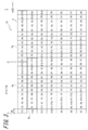
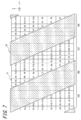
- FIG. 1 It is a figure which shows an example of the head-up display system mounted on the moving body. It is a figure which shows the schematic structure of the display device shown in FIG. It is a figure which shows the example which looked at the display panel shown in FIG. 2 from the depth direction. It is a figure which shows the example which looked at the parallax barrier shown in FIG. 2 from the depth direction. It is a figure for demonstrating the relationship between the virtual image shown in FIG. 1 and a user's eye. It is a figure which shows the region which can be seen from the left eye in the virtual image of a display panel. It is a figure which shows the region which can be seen from the right eye in the virtual image of a display panel.
- head-up display which is a basic configuration of the head-up display of the present disclosure
- an image having a discrepancy is propagated to the left and right eyes of the user, and the image is visually recognized as a three-dimensional image having depth in the user's field of view.
- Head-up displays that project virtual images are known.
- a head-up display that displays a 3D image as a virtual image in the user's field of view
- the head-up display displays an image having a parallax corresponding to the distance to the object at a position where the object is visually recognized by the user.
- the process of superimposing a three-dimensional image on an object and displaying it preferably has a low load on the process.
- an object of the present disclosure made by paying attention to the above points is to provide a head-up display, a head-up display system, and a moving body capable of reducing the processing load related to the display of a three-dimensional image displayed superimposed on an object. There is.
- the head-up display system 100 includes a first detection device 1, a second detection device 2, and a head-up display (HUD) 3. ..
- the head-up display system 100 may be mounted on the moving body 20.
- the interocular direction which is the direction of a straight line passing through the left eye 31l and the right eye 31r of the user 30, is represented as the x-axis direction.
- the front-back direction of the user 30 is represented as the z-axis direction.
- the height direction perpendicular to the x-axis direction and the z-axis direction is represented as the y-axis direction.
- the x-axis direction, the y-axis direction, and the z-axis direction are defined in the same manner.
- the head-up display system 100 is configured to detect the position information of the object 40 located in front of the user 30 (in the z-axis direction) by using the first detection device 1.
- the position information of the object 40 includes the distance information from the moving body 20 or the user 30 to the object 40.
- the first detection device 1 is configured to output the position information of the object 40 to the HUD 3 as the first position information.
- a distance measuring device can be used as the first detection device 1.
- Distance measuring devices include, for example, stereo cameras, infrared radars, millimeter wave radars, riders, and the like.
- the distance measuring device includes a device that calculates a distance from a plurality of monocular camera images.
- the first detection device 1 may use a composite device using a plurality of distance measuring devices.
- Stereo cameras include a plurality of cameras that have parallax with each other and cooperate with each other. Stereo cameras include at least two or more cameras. With a stereo camera, it is possible to collaborate with a plurality of cameras to capture an object from a plurality of directions. The stereo camera can detect the distance to the object based on the information on the arrangement of the plurality of cameras and the parallax of the object included in the images captured by the plurality of cameras.
- the rider is configured to spatially scan, for example, a pulsed laser beam and detect the reflected light that hits an object and is reflected.
- the rider can detect the direction of the object by detecting the direction in which the laser beam is reflected by the object.
- the rider can detect the distance to the object by measuring the time until the laser beam is reflected by the object and returned. Riders may be referred to as "LiDAR (Light Detection and Ringing, or Laser Imaging Detection and Ringing)".
- the first detection device 1 may be fixed to the front side of the moving body 20 with the measurement direction facing the front of the moving body 20.
- the first detection device 1 is installed in the room of the moving body 20.
- the first detection device 1 may detect the position of the object 40 in front of the moving body 20 through, for example, the windshield.
- the first detection device 1 may be fixed to any of the front bumper, fender grille, side fender, light module, and bonnet of the moving body 20.
- the first detection device 1 is configured to be able to detect the positions of various objects 40 outside the moving body 20.
- the object 40 that can be detected by the first detection device 1 may include other vehicles traveling in front, pedestrians, road signs, obstacles on the road, and the like.
- the first detection device 1 is configured to be able to output the position information of the object 40.
- the position information of the object 40 can be represented by a Cartesian coordinate system having an arbitrary position of the first detection device 1 or the moving body 20 as the origin.
- the position of the object 40 can be represented by a polar coordinate system whose origin is an arbitrary position of the first detection device 1 or the moving body 20.
- the first detection device 1 may be shared with a system other than the head-up display system 100.
- the first detection device 1 can be shared with a system such as brake control, inter-vehicle distance control with a vehicle in front, and peripheral monitoring of the moving body 20.
- the head-up display system 100 is configured to detect the position of the eye 31 of the user 30 who observes the three-dimensional image by using the second detection device 2.
- the eye 31 of the user 30 includes the left eye 31l (first eye) and the right eye 31r (second eye) of the user 30.
- the left eye 31l and the right eye 31r of the user 30 are not particularly distinguished, the left eye 31l and the right eye 31r are collectively referred to as the eye 31.
- the second detection device 2 outputs the position of the detected eye 31 of the user 30 to the HUD 3.
- the head-up display system 100 is mounted on the mobile body 20, the user 30 may be the driver of the mobile body 20.
- the second detection device 2 may include an image pickup device or a sensor.
- the second detection device 2 is configured to output the position information of the eye 31 of the user 30 to the HUD 3 as the second position information.
- the second detection device 2 may be mounted on or near the rearview mirror.
- the second detector 2 may be mounted within the instrument panel, eg, in a cluster.
- the second detection device 2 may be attached to the center panel.
- the second detection device 2 may be attached to a support portion of the steering wheel, which is arranged at the center of the steering wheel.
- the second detection device 2 may be mounted on the dashboard.
- the image pickup device is configured to acquire an image of the subject and generate an image of the subject.
- the image pickup device includes an image pickup device.
- the image sensor may include, for example, a CCD (Charge Coupled Device) image sensor or a CMOS (Complementary Metal Oxide Semiconductor) image sensor.
- the image pickup device is arranged so that the face of the user 30 is located on the subject side.
- the second detection device 2 is configured to detect the position of at least one of the left eye 31l and the right eye 31r of the user 30.
- the second detection device 2 may be configured to detect the displacement direction and the amount of displacement of the position of the eye 31 from the origin with a predetermined position as the origin.
- the second detection device 2 may be configured to detect at least one position of the left eye 31l and the right eye 31r from the captured image of the image pickup device.
- the second detection device 2 may be configured to detect at least one position of the left eye 31l and the right eye 31r as coordinates in three-dimensional space by using two or more imaging devices.
- the second detection device 2 does not have a camera and may be connected to a camera outside the device.
- the second detection device 2 may include an input terminal configured to receive a signal input from an image pickup device outside the device.
- the imaging device outside the device may be directly connected to the input terminal.
- the imaging device outside the device may be indirectly connected to the input terminal via a shared network.
- the second detection device 2 without a camera may be configured to detect at least one position of the left eye 31l and the right eye 31r from the video signal input to the input terminal.
- the sensor may be an ultrasonic sensor, an optical sensor, or the like.
- the second detection device 2 may be configured to detect the position of the head of the user 30 by a sensor and detect the position of at least one of the left eye 31l and the right eye 31r based on the position of the head.
- the second detection device 2 may be configured to detect at least one position of the left eye 31l and the right eye 31r as coordinates in three-dimensional space by one or two or more sensors.
- the second detection device 2 is configured to detect the moving distances of the left eye 31l and the right eye 31r along the eyeball arrangement direction based on the detection result of at least one position of the left eye 31l and the right eye 31r. You may.
- the first detection device 1 and the second detection device 2 may be configured to be able to communicate with the HUD 3 via a wired or wireless communication line or a communication network such as CAN (Controller Area Network).
- CAN Controller Area Network
- the HUD 3 includes a reflector 4, an optical member 5, and a display device 6.
- the reflector 4 and the optical member 5 form an optical system of HUD3.
- the optical system of the HUD 3 may include optical elements such as a lens and a mirror in addition to the reflector 4 and the optical member 5.
- the HUD3 optics can also have a lens in place of or in addition to the reflector 4.
- the reflector 4 is configured to reflect the image light emitted from the display device 6 toward a predetermined region of the optical member 5.
- the predetermined region is a region in which the image light reflected in the predetermined region is directed toward the eye 31 of the user 30.
- the predetermined region can be determined by the direction of the eye 31 of the user 30 with respect to the optical member 5 and the incident direction of the image light on the optical member 5.
- the reflector 4 may be a concave mirror.
- the optical system including the reflector 4 may have a positive index of refraction.
- the reflector 4 may have a drive unit 15 (see FIG. 2).
- the reflector 4 may be configured so that the angle of the reflecting surface can be adjusted by the driving unit 15.
- the drive unit 15 can adjust the reflection direction of the image light toward the optical member 5 according to the position of the eye 31 detected by the second detection device 2.
- the drive unit 15 adjusts the reflection direction of the image light toward the optical member 5 based on the first position information detected by the first detection device 1 and the second position information detected by the second detection device 2. Can be done.
- the optical member 5 is configured to reflect the image light emitted from the display device 6 and reflected by the reflector 4 toward the left eye 31l and the right eye 31r of the user 30.
- the windshield of the moving body 20 may also be used as the optical member 5.
- a plate-shaped member for a head-up display called a combiner may be located inside the windshield.
- the HUD 3 causes the light emitted from the display device 6 to travel along the optical path P to the left eye 31l and the right eye 31r of the user 30.
- the user 30 can visually recognize the light arriving along the optical path P as a virtual image.
- the arrangement and configuration of the optical system of the HUD 3 including the reflector 4 and the optical member 5 determines the position of the virtual image plane on which the image light emitted from the display device 6 projects a virtual image.
- the virtual image plane can be positioned in front of the user 30 at a position 7.5 m from the eye 31 of the user 30.
- the display device 6 includes a first input unit 7, a second input unit 8, an irradiator 9, a display panel 10, a parallax barrier 11 as an optical element, a controller 12, and the like.
- the memory 13 and the output unit 14 can be included.
- the first input unit 7 is configured to be able to acquire the first position information regarding the position of the object 40 including the distance to the object 40, which is detected by the first detection device 1.
- the second input unit 8 is configured to be able to acquire the second position information regarding the position of the eye 31 of the user 30 detected by the second detection device 2.
- the first input unit 7 and the second input unit 8 have a communication function according to a communication method between the first detection device 1 and the second detection device 2, respectively.
- the first input unit 7 and the second input unit 8 include a wired and / or wireless communication interface.
- the first input unit 7 and the second input unit 8 may include connectors such as an electric connector and an optical connector that support wired communication.
- the first input unit 7 and the second input unit 8 may include an antenna corresponding to wireless communication.
- the first input unit 7 and the second input unit 8 may be composed of some or all common components.
- the output unit 14 outputs a drive signal to the drive unit 15 that adjusts the direction of the reflector 4.
- the output unit 14 may employ a physical connector and wireless communication.
- the output unit 14 may be connected to a vehicle network such as CAN (Control Area Network).
- the drive unit 15 is controlled by the controller 12 via the output unit 14.
- the irradiator 9 can be configured to irradiate the display panel 10 in a plane.
- the irradiator 9 may include a light source, a light guide plate, a diffusion plate, a diffusion sheet, and the like.
- the irradiator 9 is configured to emit the irradiation light by a light source and to make the irradiation light uniform in the surface direction of the display panel 10 by a light guide plate, a diffusion plate, a diffusion sheet or the like.
- the irradiator 9 may be configured to emit uniformed light towards the display panel 10.
- a display panel such as a transmissive liquid crystal display panel can be adopted.
- the display panel 10 is not limited to the transmissive liquid crystal panel, and a self-luminous display panel can be used.
- the self-luminous display panel may use an organic EL, an inorganic EL, or the like.
- the display device 6 does not have to include the irradiator 9.
- the display panel 10 has a plurality of compartmentalized areas on the active area A extending in a plane shape.
- the plurality of compartmentalized regions are regions designated by P1 to P12 in FIG.
- the active area A is configured to display a parallax image.
- the parallax image includes a left eye image and a right eye image, which will be described later.
- the right image has parallax with respect to the left eye image.
- One of the left eye image and the right eye image is the first image.
- the other of the left eye image and the right eye image is the second image.
- each of the plurality of compartmentalized regions is a region partitioned in the u-axis direction and the v-axis direction orthogonal to the u-axis direction.
- the direction orthogonal to the u-axis direction and the v-axis direction is referred to as the w-axis direction.
- the u-axis direction may be referred to as the horizontal direction.
- the v-axis direction may be referred to as the vertical direction.
- the w-axis direction may be referred to as the depth direction.
- the u-axis direction, the v-axis direction and the w-axis direction are the same directions as those in FIGS. 2 and 3.
- the active area A includes a plurality of subpixels arranged in a grid along the u-axis direction and the v-axis direction.
- Each subpixel corresponds to any color of R (Red), G (Green), and B (Blue), and one pixel can be configured by combining three subpixels of R, G, and B as a set. ..
- One pixel can be referred to as one pixel.
- the u-axis direction is, for example, a direction in which a plurality of subpixels constituting one pixel are arranged.
- the v-axis direction is, for example, a direction in which a plurality of subpixels of the same color are arranged.
- the plurality of subpixels arranged in the active area A constitute a plurality of subpixel group Pg under the control of the controller 12.
- the plurality of subpixel groups Pg are repeatedly arranged in the u-axis direction.
- the plurality of subpixel groups Pg can be arranged in the same column in the v-axis direction and can be arranged so as to be offset in the v-axis direction.
- a plurality of sub-pixel groups Pg can be repeatedly arranged adjacent to positions shifted by one sub-pixel in the u-axis direction in the v-axis direction.
- the plurality of subpixel group Pg includes a plurality of subpixels in a predetermined row and column.
- a plurality of sub-pixel groups Pg are continuously arranged (2 ⁇ n ⁇ ) in b (b rows) in the v-axis direction and 2 ⁇ n (2 ⁇ n columns) in the u-axis direction.
- N 2 ⁇ n ⁇ b.
- the plurality of sub-pixel groups Pg is the smallest unit that the controller 12 controls to display an image.
- Substantially simultaneous is not limited to perfect simultaneous. For example, when the sub-pixels P1 to PN are controlled based on the same clock generation, it can be said that they are controlled substantially at the same time.
- the controller 12 when the controller 12 switches the image to be displayed on the subpixel P1 from the left eye image to the right eye image, the controller 12 displays the image to be displayed on the plurality of subpixels P1 in all the subpixel group Pg from the left eye image to the right eye image. Can be switched to at virtually the same time.
- the parallax barrier 11 can be a plane along the active area A.
- the parallax barrier 11 is separated from the active area A by a distance gap g.
- the parallax barrier 11 may be located on the opposite side of the irradiator 9 with respect to the display panel 10.
- the parallax barrier 11 may be located on the irradiator 9 side of the display panel 10.
- the parallax barrier 11 is configured to define the propagation direction of image light emitted from a plurality of subpixels. As shown in FIG. 4, the parallax barrier 11 has a plurality of dimming regions 11b extending in a predetermined direction for dimming the image light. The plurality of dimming regions 11b define a translucent region 11a, which is a plurality of strip-shaped regions extending in a predetermined direction in the plane of the parallax barrier 11, between two dimming regions 11b adjacent to each other. The plurality of translucent regions 11a have a higher light transmittance than the plurality of dimmed regions 11b.
- the light transmittance of the plurality of light transmitting regions 11a can be 10 times or more, preferably 100 times or more, and more preferably 1000 times or more the light transmittance of the plurality of dimming regions 11b.
- the plurality of dimming regions 11b have a lower light transmittance than the plurality of translucent regions 11a.
- the plurality of dimming regions 11b may block the image light.
- the plurality of translucent regions 11a and the plurality of dimming regions 11b extend in a predetermined direction along the active area A and are repeatedly and alternately arranged in a direction orthogonal to the predetermined direction.
- the predetermined direction is, for example, a direction along the diagonal line of one subpixel when the display panel 10 and the parallax barrier 11 are viewed from the depth direction (w-axis direction).
- w-axis direction a direction along the diagonal line of one subpixel when the display panel 10 and the parallax barrier 11 are viewed from the depth direction (w-axis direction).
- t sub-pixels in the v-axis direction are crossed while crossing s sub-pixels in the u-axis direction. It can be in the direction across the pixel (s, t are positive integers of each other).
- the predetermined direction may be the v-axis direction.
- the parallax barrier 11 may be made of a film or a plate-like member.
- the plurality of dimming regions 11b are composed of the film or plate-shaped member.
- the plurality of light-transmitting regions 11a may be openings provided in the film or plate-shaped member.
- the film may be made of resin or may be made of other materials.
- the plate-shaped member may be made of resin, metal, or the like, or may be made of another material.
- the parallax barrier 11 is not limited to the film or plate-shaped member, and may be composed of other types of members.
- the parallax barrier 11 may be composed of a base material having a light-shielding property.
- the parallax barrier 11 may be composed of a base material containing an additive having a light-shielding property.
- a part of the image light emitted from the active area A of the display panel 10 passes through the plurality of translucent regions 11a and reaches the optical member 5 via the reflector 4.
- the image light that has reached the optical member 5 is reflected by the optical member 5 and reaches the eye 31 of the user 30.
- the eye 31 of the user 30 can recognize the first virtual image V1 which is a virtual image of the image displayed in the active area A in front of the optical member 5.
- the surface on which the first virtual image V1 is projected is called the virtual image surface Sv.
- the front is the direction of the optical member 5 as viewed from the user 30.
- the front is the direction in which the moving body 20 normally moves.
- the user 30 apparently displays an image as if the second virtual image V2, which is a virtual image of the parallax barrier 11, defines the direction of the image light from the first virtual image V1. recognize.
- the user 30 apparently recognizes the image as if the first virtual image V1 is visually recognized via the second virtual image V2.
- the second virtual image V2 which is a virtual image of the parallax barrier 11, is not visually recognized.
- the second virtual image V2 will be described as being apparently at a position where the virtual image of the parallax barrier 11 is formed and is considered to define the image light from the first virtual image V1.
- the region in the first virtual image V1 that can be visually recognized by the user 30 by the image light propagating to the position of the left eye 31l of the user 30 is referred to as a left visible region VaL.
- the region in the first virtual image V1 that can be visually recognized by the user 30 by the image light propagating to the position of the right eye 31r of the user 30 is referred to as a right visible region VaR.
- the virtual image barrier pitch VBp and the virtual image gap Vg are defined so that the following equations (1) and (2) using the appropriate viewing distance Vd hold.
- Vd (n ⁇ VHp): Vg equation (1)
- Vd: VBp (Vdv + Vg): (2 ⁇ n ⁇ VHp) Equation (2)
- the virtual image barrier pitch VBp is an arrangement interval in the x-axis direction corresponding to the u-axis direction of the plurality of dimming regions 11b projected as the second virtual image V2.
- the virtual image gap Vg is the distance between the second virtual image V2 and the first virtual image V1.
- the suitable viewing distance Vd is the distance between the positions of the left eye 31l and the right eye 31r of the user 30 and the virtual image V2 of the parallax barrier 11 indicated by the position information acquired from the second detection device 2.
- the intereye distance E is the distance between the left eye 31l and the right eye 31r.
- the intereye distance E may be, for example, 61.1 mm to 64.4 mm, which is a value calculated by research by the National Institute of Advanced Industrial Science and Technology.
- VHp is the horizontal length of the virtual image of the plurality of subpixels.
- VHp is the length of the virtual image of one subpixel in the first virtual image V1 in the direction corresponding to the x-axis direction.
- the left visible region VaL shown in FIG. 5 is left of the user 30 when the image light transmitted through the plurality of translucent regions 11a of the parallax barrier 11 reaches the left eye 31l of the user 30.
- the right visible region VaR is visually recognized by the right eye 31r of the user 30 when the image light transmitted through the plurality of translucent regions 11a of the parallax barrier 11 reaches the right eye 31r of the user 30. This is the region of the virtual image plane Sv.
- FIG. 6 shows the arrangement of a plurality of subpixels of the first virtual image V1 as seen from the left eye 31l of the user 30.
- the subpixels on the first virtual image V1 are designated by the same reference numerals P1 to P12 as the subpixels shown in FIG.
- the plurality of translucent regions 11a and the plurality of dimming regions 11b of the parallax barrier 11 have equal widths in the interocular direction (x-axis direction).
- a part of the first virtual image V1 is dimmed by the second virtual image V2 to form a left dimming region VbL.
- the left dimming region VbL is a region in which the left eye 31l of the user 30 is difficult to see because the image light is dimmed by the dimming region 11b of the parallax barrier 11.
- FIG. 6 When the virtual image of the parallax barrier 11 is located as shown in FIG. 6 when viewed from the left eye 31l of the user 30, the arrangement of a plurality of subpixels of the first virtual image V1 as seen from the right eye 31r of the user 30 is shown in FIG. Shown.
- a part of the first virtual image V1 is a right dimming region VbR dimmed by the second virtual image V2.
- the right dimming region VbR is a region that is difficult for the right eye 31r of the user 30 to see because the image light is dimmed by the dimming region 11b of the parallax barrier 11.
- the left visible region VaL corresponds to the right dimming region VbR.
- the right visible region VaR corresponds to the left dimming region VbL.
- the aperture ratio of the parallax barrier 11 is less than 50%, the left visible region VaL is included in the right dimming region VbR.
- the right visible region VaR is included in the left dimming region VbL. Therefore, the right visible region VaR cannot be seen from the left eye 31l.
- the left visible region VaL is difficult to see from the right eye 31r.
- the left visible region VaL includes the entire plurality of subpixels P2 to P5 arranged in the active area A and most of the virtual images of the plurality of subpixels P1 and P6. It is difficult for the left eye 31l of the user 30 to visually recognize the virtual images of the plurality of subpixels P7 to P12 arranged in the active area A.
- the right visible region VaR includes the entire plurality of subpixels P8 to P11 arranged in the active area A and most of the virtual images of the plurality of subpixels P7 and P12. It is difficult for the right eye 31r of the user 30 to visually recognize the virtual images of the plurality of subpixels P1 to P6 arranged in the active area A.
- the controller 12 can display the left eye image on a plurality of subpixels P1 to P6.
- the controller 12 can display the right eye image on a plurality of subpixels P7 to P12.
- the left eye 31l of the user 30 mainly visually recognizes the virtual image of the left eye image in the left visible region VaL
- the right eye 31r mainly visually recognizes the virtual image of the right eye image in the right visible region VaR. ..
- the right eye image and the left eye image are parallax images having parallax with each other. Therefore, the user 30 can visually recognize the right eye image and the left eye image as three-dimensional images.
- the memory 13 is composed of an arbitrary storage device such as a RAM (RandomAccessMemory) and a ROM (ReadOnlyMemory).
- the memory 13 may be configured to store programs for various processes, information acquired from the first input unit 7 and the second input unit 8, information converted by the controller 12, and the like.
- the memory 13 is configured to store the position information of the object 40 acquired by the first input unit 7.
- the memory 13 may be configured to store an image element 41 to be displayed as a parallax image.
- the image element 41 includes characters, figures, animations combining them, and the like.
- the controller 12 is connected to each component of the head-up display system 100 and is configured to control each component.
- the controller 12 is configured as, for example, a processor.
- the controller 12 may include one or more processors.
- the processor may include a general-purpose processor configured to load a specific program and perform a specific function, and a dedicated processor specialized for a specific process.
- the dedicated processor may include an application specific integrated circuit (ASIC).
- the processor may include a programmable logic device (PLD).
- the PLD may include an FPGA (Field-Programmable Gate Array).
- the controller 12 may be either a SoC (System-on-a-Chip) in which one or a plurality of processors cooperate, or a SiP (System In a Package).
- the controller 12 is configured to display a right eye image and a left eye image having parallax with each other on the display panel 10.
- the controller 12 is configured to be able to change the area where the left eye image is displayed and the area where the right eye image is displayed on the display panel 10 based on the position of the eye 31 of the user 30.
- the controller 12 is configured to switch and control the image displayed by each subpixel of the display panel 10 between the right eye image and the left eye image.
- the controller 12 can visually recognize the plurality of subpixels P1 to P6 when the left visible region VaL of the first virtual image V1 seen from the left eye 31l of the user 30 is at the position shown in FIG.
- the controller 12 can visually recognize the plurality of subpixels P7 to P12 when the right visible region VaR of the first virtual image V1 seen from the right eye 31r of the user 30 is at the position shown in FIG. Therefore, when the first virtual image V1 visually recognized by the user 30 is in the state of FIGS. 6 and 7, the controller 12 causes the plurality of subpixels P1 to P6 to display the left eye image, and the plurality of subpixels P7 display the left eye image.
- the right eye image can be displayed on P12.
- the controller 12 can display the left eye image on the plurality of subpixels P2 to P5 and display the right eye image on the plurality of subpixels P8 to P11.
- the controller 12 can cause a plurality of other subpixels P1, P6, P7 and P12 to display black with a luminance value of 0. In that case, the occurrence of crosstalk can be particularly reduced.
- the controller 12 displays a plurality of subpixels for displaying the left eye image from the plurality of subpixels P1 to P12 of each subpixel group Pg and a right eye image according to the position of the eye 31 of the user 30. It is configured to determine with multiple subpixels to do.
- the controller 12 is configured to display the left eye image on a plurality of subpixels determined to display the left eye image.
- the controller 12 is configured to display the right eye image on a plurality of subpixels determined to display the right eye image.
- the alternate long and short dash line is a plurality of translucent regions 11a and a plurality of dimming regions 11b of the parallax barrier 11 seen from the left eye 31l and the right eye 31r when the aperture ratio of the parallax barrier 11 is 50%. Shows a virtual image of the boundary with.
- the controller 12 can display the left eye image on the plurality of subpixels P2 to P7 of the display panel 10.
- the controller 12 can display the right eye image on the plurality of subpixels P1 and P8 to P12 of the display panel 10.
- the controller 12 gives various parallax to the image element 41 included in the parallax image composed of the left eye image and the right eye image displayed on the display panel 10, so that the distance to the image element 41 visually recognized by the user 30 can be determined. It is configured to be changeable.
- the image element 41 is individual characters and figures included in the parallax image, animations thereof, and the like.
- the parallax image may include one or more image elements 41 that are viewed by the user 30 at different distances.
- the image element 41 is displayed in the field of view of the user 30 in association with the object 40 detected by the first detection device 1.
- the image element 41 can be text information indicating the speed of the object 40.
- the image element 41 may be a graphic display that warns of a decrease in the inter-vehicle distance due to the deceleration of the preceding vehicle. It is preferable that the image element 41 displayed in association with the object 40 is at least partially overlapped with the object 40 and displayed at a distance substantially equal to the distance to the object 40. By displaying the image element 41 on top of the object 40 in the real space, it is possible to provide a visually expanded real environment.
- the controller 12 causes the controller 12 to display the image elements 41 to be displayed included in the left eye image and the right eye image so that they have a desired parallax amount.
- the parallax amount means the angle difference in the line-of-sight direction between the left eye 31l and the right eye 31r when a human looks at the object 40.
- the parallax amount can be rephrased as the convergence angle.
- the amount of parallax of the image element 41 is the convergence angle when the left eye 31l visually recognizes the left image element 42l displayed on the left eye image and the right eye 31r sees the right image element 42r displayed on the right eye image.
- the controller 12 may acquire images such as characters and figures stored in advance from the memory 13.
- the controller 12 may calculate the parallax according to the distance to the object 40 in real time, and give the parallax between the left image element 42l and the right image element 42r of the image element 41 to be displayed on the display panel 10. The operation of the controller 12 for displaying the image element 41 will be described later.
- the object 40 is located just a second distance away from the user 30 in the z-axis direction.
- the second distance is the optimum viewing distance Vd.
- the portion of the object 40 visible to the user 30 is located so as to coincide with the virtual image plane Sv.
- the controller 12 determines the convergence angle at which the left image element 42l included in the left eye image of the parallax image and the right image element 42r included in the right eye image are viewed. It may be matched with the convergence angle ⁇ for viewing a point on the virtual image plane Sv. In this case, the position where the virtual image of the image element 41 is actually projected and the position where the image element 41 is recognized to exist due to the convergence angle coincide with the virtual image plane Sv, so that the user 30 can see the image without any discomfort. Can be done.
- the object 40 is located at a position separated by a second distance or more and less than a first distance in front of the user 30 in the z-axis direction.
- the controller 12 displays the left image element 42l and the right image element 42r at different positions on the virtual image plane Sv according to the amount of parallax.
- the left image element 42l is an image viewed from the left side with a smaller inclination angle with respect to the z-axis direction than the image element 41 viewed from the optimum viewing distance Vd.
- the right image element 42r is an image viewed from the right side with a smaller inclination angle with respect to the z-axis direction than the image element 41 viewed from the optimum viewing distance Vd.
- the user 30 perceives that the image element 41 exists at a position where the line-of-sight direction from the left eye 31l to the left image element 42l and the line-of-sight direction from the right eye 31r to the right image element 42r intersect. To do.
- the convergence angle at which the left eye 31l and the right eye 31r see the point on the image element 41 is represented by the convergence angle ⁇ 1.
- the convergence angle ⁇ 1 is smaller than the convergence angle ⁇ for viewing a point on the virtual image plane Sv.
- the user 30 can image as if the image element 41 exists further in front of the virtual image surface Sv.
- the element 41 is visually recognized.
- the processing load of HUD3 may increase.
- the parallax amount given to the image element 41 is the parallax amount corresponding to the first distance.
- the image element 41 superimposed on the object 40 is located substantially equidistant from the distance to the object 40 by the cognitive function of the human brain. Recognized to do.
- the human brain automatically synthesizes the image elements 41 having different parallax so that they are located at substantially the same distance as the object 40. It is thought to be the body. According to the experiments of the inventors of the present application, it was confirmed that such an effect can be obtained when the first distance is at least 12.5 m and the second distance is 7.5 m.
- the object 40 is located at the same distance as the image element 41 object 40. I saw it. Phenomena such as the boundary of the image element 41 appearing double or blurred due to the difference in the convergence angle did not occur.
- the controller 12 displays at least partially superimposed on the object 40 in the first control.
- the parallax amount of the image element 41 is configured to be fixed to the parallax amount corresponding to the first distance.
- the HUD3 can make the user 30 recognize the image element 41 so as to be located substantially equidistant from the distance to the object 40 by the cognitive function of the human brain.
- the user 30 recognizes that the image element 41 is located at the position of the object 40, not at the image display position 43 corresponding to the distance based on the parallax.
- the parallax amount of the image element 41 is not 0 at the first distance. That is, the present disclosure is completely different from the one in which the parallax in the region where there is almost no parallax is fixed to 0 because it is located at a long distance.
- the parallax amount of the image element 41 has a size sufficiently recognized by human vision when the image element 41 is displayed without being superimposed on the object 40.
- the convergence angle at which the left eye 31l and the right eye 31r see a point on the left image element 42l on the left eye image and the right image element 42r on the right eye image is fixed at a convergence angle ⁇ 2 smaller than ⁇ 1. ..
- the convergence angle ⁇ 2 is a convergence angle for observing a point located at the first distance.
- a display example of the image element 41 according to the embodiment will be described with reference to FIG. FIG. 12 includes a preceding vehicle 45 traveling ahead at a distance longer than the first distance as an example of the object 40.
- the first detection device 1 is configured to acquire position information including the distance to the preceding vehicle 45 in time series and transmit it to the controller 12. If the preceding vehicle 45 starts decelerating, the controller 12 recognizes this by shortening the distance to the preceding vehicle 45 acquired from the first detection device 1. In order to call attention to the user 30, the controller 12 controls the display panel 10 to indicate that the preceding vehicle 45 is decelerating so as to be superimposed on the preceding vehicle 45 in the field of view of the user 30. 41 is displayed.
- the display of the image element 41 may include characters and / or figures and the like.
- the display of the image element 41 may be accompanied by animations such as movement, blinking, and / or shape change.
- the image element 41 is a parallax image having a parallax corresponding to the first distance.
- the image element 41 is recognized to be located equidistant from the preceding vehicle 45 by the cognitive function of the brain of the user 30. When the distance from the user 30 to the preceding vehicle 45 changes, the image element 41 is recognized to follow the preceding vehicle 45.
- the controller 12 acquires the first position information of the object 40 that the user 30 can visually recognize forward through the optical member 5 from the first input unit 7 (step S01).
- the controller 12 acquires the second position information regarding the position of the eye 31 of the user 30 from the second input unit 8 (step S02).
- Step S02 may be executed before step S01.
- Step S02 may be performed in parallel with step S01.
- the controller 12 determines whether or not the distance to the object 40 is longer than the first distance based on the first position information (step S03).
- the first distance is, for example, 12.5 m.
- the first distance can be longer than 12.5 m.
- step S03 When it is determined in step S03 that the distance to the object 40 is equal to or greater than the first distance (step S03: Yes), the controller 12 executes the first control (step S04).
- the controller 12 fixes the parallax amount given to the image element 41 to the parallax amount corresponding to the first distance.
- the parallax amount corresponding to the first distance is a parallax amount larger than 0.
- step S05 the controller 12 controls the parallax amount given to the image element 41 so as to be the parallax amount corresponding to the distance to the object 40. For example, when the distance to the object 40 is 10 m, the controller 12 provides the same parallax between the left image element 42l and the right image element 42r as when looking at a point 10 m ahead.
- step S05 when the distance to the object 40 is shorter than the second distance, the controller 12 displays the image element 41 on the front side of the user 30 from the virtual image plane Sv.
- the second distance is an appropriate viewing distance Vd.
- the second distance can be longer than 7.5 m and shorter than the first distance.
- the controller 12 can perform a process different from that in step S05. For example, when the distance to the object 40 is shorter than the second distance, the controller 12 may fix the parallax amount of the image element 41 to the parallax amount corresponding to the second distance.
- the controller 12 generates an image element 41 that is superimposed on the object 40 and displayed (step S06). For example, the controller 12 determines the image element 41 to be displayed based on the distance to the object 40 included in the position information of the object 40 acquired in step S01, its change, and the like. The controller 12 may receive an instruction from another device of the moving body 20 about the image element 41 to be displayed. The controller 12 determines the display position of the image element 41 on the display panel 10 based on the position information of the object 40 acquired in step S01 and the position information of the eye 31 of the user 30 acquired in step S02. The controller 12 causes the image element 41 to be at least partially superimposed on the object 40 visible to the user 30.
- the controller 12 may drive the drive unit 15 via the output unit 14 to adjust the display position of the image element 41, if necessary.
- the controller 12 imparts parallax to the image element 41 based on the parallax amount determined in step S04 or step S05.
- the controller 12 is configured to combine one or more image elements 41 with a parallax image.
- the controller 12 displays the combined parallax image on the display panel 10 (step S07).
- the image element 41 is displayed superimposed on the object 40 in the field of view of the user 30.
- the image element 41 is recognized by the user 30 as being displayed at a position equidistant from the object 40.
- the controller 12 when the distance to the object 40 is the first distance or more, the controller 12 is configured so that the parallax amount of the image element 41 is fixed and not controlled. To. As a result, the head-up display system 100 can reduce the processing load related to the composition and display of the three-dimensional image displayed superimposed on the object 40.
- the three-dimensional display device between the distance to the display surface on which the image is actually displayed (virtual image surface Sv in the present application) and the distance to the display image perceived by the user 30 due to the parallax given to both eyes. It is known that if the difference is large, it causes discomfort, visual fatigue, and the like. In the HUD3 of the present disclosure, it is not necessary to increase the difference between the second distance corresponding to the distance to the virtual image plane Sv and the first distance, so that discomfort, visual fatigue, and the like can be reduced.
- the parallax barrier 11 is used as an optical element for propagating the left eye image and the right eye image displayed on the display panel 10 to the left eye 31l and the right eye 31r of the user 30, respectively. ..
- the optical elements that can be used are not limited to the parallax barrier 11.
- a liquid crystal shutter or a lenticular lens can be used instead of the parallax barrier 11.
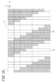
- FIG. 14 is a configuration example of the display device 6A using the liquid crystal shutter 16 instead of the parallax barrier 11. The configuration and operation of the display device 6A will be described below with reference to FIGS. 14 and 15.
- the liquid crystal shutter 16 is controlled by the controller 12.
- the display device 6A is configured in the same manner as the display device 6 of FIG. 2 except that the liquid crystal shutter 16 is used instead of the parallax barrier 11.
- the liquid crystal shutter 16 may be configured similar to the display panel 10.
- the liquid crystal shutter 16 is composed of a plurality of pixels P.
- the liquid crystal shutter 16 is configured to be able to control the light transmittance in each pixel P.
- the plurality of pixels P of the liquid crystal shutter correspond to the plurality of sub-pixels of the display panel 10.
- the plurality of pixels P of the liquid crystal shutter 16 are different from the display panel 10 in that they do not have a color component.
- each pixel P of the liquid crystal shutter 16 is the same as each subpixel of the display panel 10. They may be arranged in shape and size.
- the liquid crystal shutter 16 has a plurality of light-transmitting regions 16a and a plurality of dimming regions 16b under the control of the controller 12.
- the light transmittances of the plurality of translucent regions 16a and the plurality of dimming regions 16b can be set to be the same as those of the plurality of translucent regions 11a and the plurality of dimming regions 11b of the parallax barrier 11, respectively.
- the plurality of translucent regions 16a and the plurality of dimming regions 16b by the liquid crystal shutter 16 are regions corresponding to the arrangement of the plurality of pixels of the liquid crystal shutter 16.
- the boundary between the plurality of light transmitting regions 16a and the plurality of dimming regions 16b can be stepped corresponding to the shape of the plurality of pixels P.
- the boundary between the plurality of translucent regions 16a and the plurality of dimming regions 16b of the liquid crystal shutter 16 can be dynamically changed so as to reduce crosstalk.
- the controller 12 replaces switching the display image for each subpixel of the display panel 10 with a plurality of translucent regions of the liquid crystal shutter 16. It is possible to switch between 16a and a plurality of dimming regions 16b.
- the controller 12 is configured to control the liquid crystal shutter 16 so that the image light from the plurality of subpixels P1 to P6 displaying the left eye image is directed to the left eye 31l of the user 30 at the highest ratio. Will be done.
- the controller 12 is configured to control the liquid crystal shutter 16 so that the image light from the plurality of subpixels P7 to P12 displaying the right eye image is directed to the right eye 31r of the user 30 at the highest ratio.
- each component or each step can be rearranged so as not to be logically inconsistent, and a plurality of components or steps can be combined or divided into one.
- the embodiment according to the present disclosure can also be realized as a method, a program, or a storage medium on which a program is recorded, which is executed by a processor included in the apparatus. It should be understood that the scope of this disclosure also includes these.
- the descriptions such as “first” and “second” are identifiers for distinguishing the configuration.
- the configurations distinguished by the descriptions such as “first” and “second” in the present disclosure can exchange numbers in the configurations.
- the first input unit can exchange the identifiers “first” and “second” with the second input unit.
- the exchange of identifiers takes place at the same time.
- the configuration is distinguished.
- the identifier may be deleted.
- the configuration with the identifier removed is distinguished by a code. Based solely on the description of identifiers such as “first” and “second” in the present disclosure, it shall not be used as a basis for interpreting the order of the configurations and for the existence of identifiers with smaller numbers.
- the x-axis direction, the y-axis direction, and the z-axis direction are provided for convenience of explanation and may be interchanged with each other.
- the configuration according to the present disclosure has been described using a Cartesian coordinate system whose axes are the x-axis direction, the y-axis direction, and the z-axis direction.
- the positional relationship of each configuration according to the present disclosure is not limited to being orthogonal. The same applies to the u-axis direction, the v-axis direction, and the w-axis direction.
- Mobile in the present disclosure includes vehicles, ships, and aircraft.
- Vehicles in the present disclosure include, but are not limited to, automobiles and industrial vehicles, and may include railway vehicles, living vehicles, and fixed-wing aircraft traveling on runways.
- Automobiles include, but are not limited to, passenger cars, trucks, buses, motorcycles, trolley buses and the like, and may include other vehicles traveling on the road.
- Industrial vehicles include industrial vehicles for agriculture and construction.
- Industrial vehicles include, but are not limited to, forklifts and golf carts.
- Industrial vehicles for agriculture include, but are not limited to, tractors, cultivators, transplanters, binders, combines, and lawnmowers.
- Industrial vehicles for construction include, but are not limited to, bulldozers, scrapers, excavators, cranes, dump trucks, and road rollers. Vehicles include those that run manually.
- the classification of vehicles is not limited to the above.
- an automobile may include an industrial vehicle capable of traveling on a road, and the same vehicle may be included in a plurality of classifications.
- Ships in the present disclosure include marine jets, boats and tankers.
- Aircraft in the present disclosure include fixed-wing aircraft and rotary-wing aircraft.
- the head-up display of the present disclosure includes a first input unit, a second input unit, a display panel, an optical system, a processor, and an optical element.
- the first input unit is configured to be able to acquire first position information regarding the position of the object including the distance to the object.
- the second input unit is configured to be able to acquire second position information regarding the position of the user's eyes.
- the optical system is configured to project a virtual image of an image displayed on the display panel within the field of view of the user.
- the processor is configured to display a parallax image including a first image and a second image having parallax with each other on the display panel.
- the optical element propagates the first image displayed on the display panel to the user's first eye via the optical system, and the second image displayed on the display panel is transmitted to the user's first eye. It is configured to propagate to the second eye.
- the processor Based on the first position information and the second position information, the processor includes an image element included in the parallax image on the display panel so as to at least partially superimpose on the object viewed by the user. Is displayed.
- the processor executes a first control for fixing the parallax amount of the image element to a parallax amount larger than 0 corresponding to the first distance. It is composed.
- the head-up display system of the present disclosure includes a first detection device, a second detection device, and a head-up display.
- the first detection device is configured to be capable of detecting first position information regarding the position of the object, including the distance to the object.
- the second detection device is configured to be capable of detecting second position information regarding the position of the user's eyes.
- the head-up display includes a first input unit, a second input unit, a display panel, an optical system, a processor, and an optical element.
- the first input unit is configured to be able to acquire the first position information from the first detection device.
- the second input unit is configured to be able to acquire the second position information from the second detection device.
- the optical system is configured to project a virtual image of an image displayed on the display panel within the field of view of the user.
- the processor is configured to display a parallax image including a first image and a second image having parallax with each other on the display panel.
- the optical element propagates the first image displayed on the display panel to the user's first eye via the optical system, and the second image displayed on the display panel is transmitted to the user's first eye. It is configured to propagate to the second eye.
- the processor Based on the first position information and the second position information, the processor includes an image element included in the parallax image on the display panel so as to at least partially superimpose on the object viewed by the user. Is displayed.
- the processor is configured to fix the parallax amount of the image element to a parallax amount greater than 0 corresponding to the first distance when the distance to the object is a predetermined first distance or more.
- the mobile body of the present disclosure is equipped with a head-up display system.
- the head-up display system includes a first detection device, a second detection device, and a head-up display.
- the first detection device is configured to be capable of detecting first position information regarding the position of the object, including the distance to the object.
- the second detection device is configured to be capable of detecting second position information regarding the position of the user's eyes.
- the head-up display includes a first input unit, a second input unit, a display panel, an optical system, a processor, and an optical element.
- the first input unit is configured to be able to acquire the first position information from the first detection device.
- the second input unit is configured to be able to acquire the second position information from the second detection device.
- the optical system is configured to project a virtual image of an image displayed on the display panel within the field of view of the user.
- the processor is configured to display a parallax image including a first image and a second image having parallax with each other on the display panel.
- the optical element propagates the first image displayed on the display panel to the user's first eye via the optical system, and the second image displayed on the display panel is transmitted to the user's first eye. It is configured to propagate to the second eye.
- the processor Based on the first position information and the second position information, the processor includes an image element included in the parallax image on the display panel so as to at least partially superimpose on the object viewed by the user. Is displayed.
- the processor is configured to fix the parallax amount of the image element to a parallax amount greater than 0 corresponding to the first distance when the distance to the object is a predetermined first distance or more.
Landscapes
- Engineering & Computer Science (AREA)
- Physics & Mathematics (AREA)
- Transportation (AREA)
- Chemical & Material Sciences (AREA)
- Combustion & Propulsion (AREA)
- Mechanical Engineering (AREA)
- General Physics & Mathematics (AREA)
- Optics & Photonics (AREA)
- Multimedia (AREA)
- Signal Processing (AREA)
- Computer Hardware Design (AREA)
- Theoretical Computer Science (AREA)
- Testing, Inspecting, Measuring Of Stereoscopic Televisions And Televisions (AREA)
- Controls And Circuits For Display Device (AREA)
- Instrument Panels (AREA)
Priority Applications (4)
| Application Number | Priority Date | Filing Date | Title |
|---|---|---|---|
| US17/774,016 US20230001790A1 (en) | 2019-11-05 | 2020-11-10 | Head-up display, head-up display system, and movable body |
| EP20883735.1A EP4057049A4 (en) | 2019-11-05 | 2020-11-10 | HEAD-UP DISPLAY, HEAD-UP DISPLAY SYSTEM, AND MOVING BODY |
| JP2021555145A JP7346587B2 (ja) | 2019-11-05 | 2020-11-10 | ヘッドアップディスプレイ、ヘッドアップディスプレイシステム及び移動体 |
| CN202080077675.XA CN114761857A (zh) | 2019-11-05 | 2020-11-10 | 平视显示器、平视显示器系统以及移动体 |
Applications Claiming Priority (2)
| Application Number | Priority Date | Filing Date | Title |
|---|---|---|---|
| JP2019201004 | 2019-11-05 | ||
| JP2019-201004 | 2019-11-05 |
Publications (1)
| Publication Number | Publication Date |
|---|---|
| WO2021090956A1 true WO2021090956A1 (ja) | 2021-05-14 |
Family
ID=75849177
Family Applications (1)
| Application Number | Title | Priority Date | Filing Date |
|---|---|---|---|
| PCT/JP2020/041872 Ceased WO2021090956A1 (ja) | 2019-11-05 | 2020-11-10 | ヘッドアップディスプレイ、ヘッドアップディスプレイシステム及び移動体 |
Country Status (5)
| Country | Link |
|---|---|
| US (1) | US20230001790A1 (https=) |
| EP (1) | EP4057049A4 (https=) |
| JP (1) | JP7346587B2 (https=) |
| CN (1) | CN114761857A (https=) |
| WO (1) | WO2021090956A1 (https=) |
Families Citing this family (4)
| Publication number | Priority date | Publication date | Assignee | Title |
|---|---|---|---|---|
| US12236814B2 (en) * | 2022-05-26 | 2025-02-25 | Industrial Technology Research Institute | Display method and display system for anti-dizziness reference image |
| CN116736529A (zh) * | 2023-06-19 | 2023-09-12 | 融信信息科技有限公司 | 一种ar-hud光学视差计算方法 |
| US20250370256A1 (en) * | 2024-05-30 | 2025-12-04 | E-Lead Electronic Co., Ltd. | Autostereoscopic display device with partitioning backlight |
| US20250370265A1 (en) * | 2024-05-30 | 2025-12-04 | E-Lead Electronic Co., Ltd. | Autostereoscopic display device with high brightness and a wide field of view |
Citations (3)
| Publication number | Priority date | Publication date | Assignee | Title |
|---|---|---|---|---|
| JP2009008722A (ja) | 2007-06-26 | 2009-01-15 | Univ Of Tsukuba | 3次元ヘッドアップディスプレイ装置 |
| JP2015194709A (ja) * | 2014-03-28 | 2015-11-05 | パナソニックIpマネジメント株式会社 | 画像表示装置 |
| JP2016107945A (ja) * | 2014-12-10 | 2016-06-20 | 株式会社リコー | 情報提供装置、情報提供方法及び情報提供用制御プログラム |
Family Cites Families (4)
| Publication number | Priority date | Publication date | Assignee | Title |
|---|---|---|---|---|
| JP6481445B2 (ja) * | 2015-03-23 | 2019-03-13 | 日本精機株式会社 | ヘッドアップディスプレイ |
| CN109863747A (zh) * | 2016-10-28 | 2019-06-07 | 三菱电机株式会社 | 显示控制装置及显示控制方法 |
| EP3554069B1 (en) * | 2016-12-07 | 2021-09-15 | Kyocera Corporation | Image projection device, image display device, and moving body |
| CN107561714A (zh) * | 2017-10-25 | 2018-01-09 | 上海驾馥电子科技有限公司 | 一种通过3d显示技术增强现实的抬头显示器 |
-
2020
- 2020-11-10 US US17/774,016 patent/US20230001790A1/en not_active Abandoned
- 2020-11-10 WO PCT/JP2020/041872 patent/WO2021090956A1/ja not_active Ceased
- 2020-11-10 EP EP20883735.1A patent/EP4057049A4/en not_active Withdrawn
- 2020-11-10 JP JP2021555145A patent/JP7346587B2/ja active Active
- 2020-11-10 CN CN202080077675.XA patent/CN114761857A/zh active Pending
Patent Citations (3)
| Publication number | Priority date | Publication date | Assignee | Title |
|---|---|---|---|---|
| JP2009008722A (ja) | 2007-06-26 | 2009-01-15 | Univ Of Tsukuba | 3次元ヘッドアップディスプレイ装置 |
| JP2015194709A (ja) * | 2014-03-28 | 2015-11-05 | パナソニックIpマネジメント株式会社 | 画像表示装置 |
| JP2016107945A (ja) * | 2014-12-10 | 2016-06-20 | 株式会社リコー | 情報提供装置、情報提供方法及び情報提供用制御プログラム |
Non-Patent Citations (1)
| Title |
|---|
| See also references of EP4057049A4 |
Also Published As
| Publication number | Publication date |
|---|---|
| CN114761857A (zh) | 2022-07-15 |
| US20230001790A1 (en) | 2023-01-05 |
| EP4057049A1 (en) | 2022-09-14 |
| JPWO2021090956A1 (https=) | 2021-05-14 |
| EP4057049A4 (en) | 2023-11-15 |
| JP7346587B2 (ja) | 2023-09-19 |
Similar Documents
| Publication | Publication Date | Title |
|---|---|---|
| JP7346587B2 (ja) | ヘッドアップディスプレイ、ヘッドアップディスプレイシステム及び移動体 | |
| CN114730096A (zh) | 平视显示器系统以及移动体 | |
| WO2021106690A1 (ja) | ヘッドアップディスプレイシステムおよび移動体 | |
| WO2021106664A1 (ja) | ヘッドアップディスプレイ、ヘッドアップディスプレイシステム及び移動体 | |
| US12313847B2 (en) | Head-up display, head-up display system, and movable body | |
| WO2022019154A1 (ja) | 3次元表示装置 | |
| US11874464B2 (en) | Head-up display, head-up display system, moving object, and method of designing head-up display | |
| WO2019225400A1 (ja) | 画像表示装置、画像表示システム、ヘッドアップディスプレイおよび移動体 | |
| US20230004003A1 (en) | Head-up display system and movable body | |
| JP2019148638A (ja) | 画像表示装置、ヘッドアップディスプレイシステム、および移動体 | |
| JP7336782B2 (ja) | 3次元表示装置、3次元表示システム、ヘッドアップディスプレイ、及び移動体 | |
| JP7344308B2 (ja) | ヘッドアップディスプレイおよび移動体 | |
| JP7274392B2 (ja) | カメラ、ヘッドアップディスプレイシステム、及び移動体 | |
| WO2022149599A1 (ja) | 3次元表示装置 | |
| WO2022065355A1 (ja) | 3次元表示装置、3次元表示方法、3次元表示システム、および移動体 | |
| JP7332449B2 (ja) | ヘッドアップディスプレイモジュール、ヘッドアップディスプレイシステム及び移動体 | |
| WO2024181153A1 (ja) | 虚像表示装置、虚像表示方法、プログラム、及び移動体 | |
| WO2020256154A1 (ja) | 3次元表示装置、3次元表示システム、および移動体 | |
| JP2021056254A (ja) | パララックスバリア、3次元表示装置、3次元表示システム、ヘッドアップディスプレイ、および移動体 |
Legal Events
| Date | Code | Title | Description |
|---|---|---|---|
| 121 | Ep: the epo has been informed by wipo that ep was designated in this application |
Ref document number: 20883735 Country of ref document: EP Kind code of ref document: A1 |
|
| ENP | Entry into the national phase |
Ref document number: 2021555145 Country of ref document: JP Kind code of ref document: A |
|
| NENP | Non-entry into the national phase |
Ref country code: DE |
|
| ENP | Entry into the national phase |
Ref document number: 2020883735 Country of ref document: EP Effective date: 20220607 |