WO2021090398A1 - サービスカバーを備えている装置 - Google Patents
サービスカバーを備えている装置 Download PDFInfo
- Publication number
- WO2021090398A1 WO2021090398A1 PCT/JP2019/043474 JP2019043474W WO2021090398A1 WO 2021090398 A1 WO2021090398 A1 WO 2021090398A1 JP 2019043474 W JP2019043474 W JP 2019043474W WO 2021090398 A1 WO2021090398 A1 WO 2021090398A1
- Authority
- WO
- WIPO (PCT)
- Prior art keywords
- groove
- terminal block
- housing
- cable
- rib
- Prior art date
Links
Images


Classifications
-
- H—ELECTRICITY
- H01—ELECTRIC ELEMENTS
- H01R—ELECTRICALLY-CONDUCTIVE CONNECTIONS; STRUCTURAL ASSOCIATIONS OF A PLURALITY OF MUTUALLY-INSULATED ELECTRICAL CONNECTING ELEMENTS; COUPLING DEVICES; CURRENT COLLECTORS
- H01R13/00—Details of coupling devices of the kinds covered by groups H01R12/70 or H01R24/00 - H01R33/00
- H01R13/46—Bases; Cases
- H01R13/52—Dustproof, splashproof, drip-proof, waterproof, or flameproof cases
-
- H—ELECTRICITY
- H01—ELECTRIC ELEMENTS
- H01R—ELECTRICALLY-CONDUCTIVE CONNECTIONS; STRUCTURAL ASSOCIATIONS OF A PLURALITY OF MUTUALLY-INSULATED ELECTRICAL CONNECTING ELEMENTS; COUPLING DEVICES; CURRENT COLLECTORS
- H01R9/00—Structural associations of a plurality of mutually-insulated electrical connecting elements, e.g. terminal strips or terminal blocks; Terminals or binding posts mounted upon a base or in a case; Bases therefor
-
- H—ELECTRICITY
- H01—ELECTRIC ELEMENTS
- H01H—ELECTRIC SWITCHES; RELAYS; SELECTORS; EMERGENCY PROTECTIVE DEVICES
- H01H85/00—Protective devices in which the current flows through a part of fusible material and this current is interrupted by displacement of the fusible material when this current becomes excessive
- H01H85/02—Details
- H01H85/20—Bases for supporting the fuse; Separate parts thereof
-
- H—ELECTRICITY
- H01—ELECTRIC ELEMENTS
- H01H—ELECTRIC SWITCHES; RELAYS; SELECTORS; EMERGENCY PROTECTIVE DEVICES
- H01H9/00—Details of switching devices, not covered by groups H01H1/00 - H01H7/00
- H01H9/02—Bases, casings, or covers
-
- H—ELECTRICITY
- H01—ELECTRIC ELEMENTS
- H01R—ELECTRICALLY-CONDUCTIVE CONNECTIONS; STRUCTURAL ASSOCIATIONS OF A PLURALITY OF MUTUALLY-INSULATED ELECTRICAL CONNECTING ELEMENTS; COUPLING DEVICES; CURRENT COLLECTORS
- H01R13/00—Details of coupling devices of the kinds covered by groups H01R12/70 or H01R24/00 - H01R33/00
- H01R13/46—Bases; Cases
Definitions
- the present specification includes a housing that houses the terminal block and has an opening, and a plurality of cables that pass through the opening from the outside of the housing and reach the terminal block. It relates to a device in which the opening through which the cable is passed is covered with a service cover.
- a technique is known in which a terminal block is provided inside the housing and an opening is provided in the housing in order to connect the bus bar located inside the housing and the cable extending outside the housing.
- the end of the bus bar is fixed to the terminal block, and the cable passes through the housing opening.
- Connect the cable to the bus bar by fixing the end of the cable to the terminal block to which the bus bar is fixed.
- the device disclosed in Japanese Patent Application Laid-Open No. 10-172635 (referred to as a lightning surge protection device in Document 1) includes a terminal block and a service cover (referred to as a case lid in Document 1). ing.
- the terminal block of Document 1 is provided with a protruding portion extending from between the ends of adjacent bus bars (referred to as connection terminals in Document 1) toward the service cover side, and the tip of the protruding portion.
- a recess is formed on the surface.
- the service cover of Document 1 includes a protrusion that meshes with the recess.
- the protruding portion on the terminal block side (to be exact, the concave portion formed at the tip thereof) and the protruding portion on the service cover side mesh with each other to block between the ends of adjacent bus bars. There is.
- the terminal block of Document 1 is provided with a protruding portion that stands between the ends of adjacent bus bars. Therefore, in the terminal block of Document 1, it is necessary to secure a workspace between the end portion of the bus bar and the protruding portion, and it is necessary to widen the distance between the end portions of the adjacent bus bars.
- the present specification discloses an apparatus in which the size of the terminal block is reduced and measures are taken against a short circuit between the ends of adjacent bus bars.
- the devices disclosed in the present specification include a housing in which a terminal block is housed and an opening is formed, a plurality of cables passing through the opening from the outside of the housing and reaching the terminal block, and a plurality of cables. It has a service cover that covers the opening through which the book cable passes.
- each end of a plurality of bus bars is arranged adjacent to each other, and a groove extending between the adjacent ends is formed. The end of each cable is fixed to the end of the corresponding bus bar with screws.
- the service cover of the apparatus disclosed herein is formed with ribs that pass through the openings and enter the grooves.
- the rib of the service cover enters the groove between the ends of the adjacent bus bars. Ribs and grooves block between the ends of adjacent bass bars. Even if a foreign substance that short-circuits the ends of adjacent bus bars enters the housing, the ribs and grooves prevent the foreign substance from moving to a position that short-circuits the adjacent ends.
- the rib and the groove may not be in contact with each other while the service cover is fixed to the housing.
- the service cover and the inner surface of the groove do not interfere with each other.
- the service cover can be securely fixed to the housing.
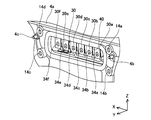
- FIG. 1 shows a side view of the mechanical / electrical integrated device 2 including the power conversion device 4 of the embodiment.
- the mechanical / electrical integrated device 2 is arranged in the front compartment of an electric vehicle (not shown).
- the mechatronics integrated device 2 includes a power conversion device 4 and a transaxle 6.
- the power conversion device 4 is arranged on the upper surface of the transaxle 6.
- the transaxle 6 includes a motor 9 for driving an electric vehicle, a power distribution device 8, and a differential gear 7.
- the motor 9 is a three-phase AC motor.
- the transaxle 6 includes two three-phase AC motors, which are not shown in FIG. In the following, one motor 9 will be focused on and described.
- the power conversion device 4 includes an inverter and a converter (not shown) in the housing 4a.
- the power conversion device 4 boosts the DC power of the main battery (not shown) of the electric vehicle by the converter in the housing 4a, and uses the DC power boosted by the inverter in the housing 4a to drive the motor 9 of the transformer axle 6. Convert to suitable AC power.
- the power conversion device 4 and the transaxle 6 are connected by a plurality of cables 20. As shown in FIG. 1, the power converter 4 and the transaxle 6 are connected by six cables 20. Since the motor 9 is a three-phase AC motor, it has three input terminals (not shown) of V phase, U phase, and W phase. The power conversion device 4 transmits two sets of three-phase alternating current to the two motors of the transaxle 6 with six cables 20.
- the power conversion device 4 is provided with a service cover 10 on the side surface of the housing 4a on the positive side in the Y-axis direction (that is, the front side of the paper surface).
- the service cover 10 is fixed to the transaxle 6 side and the positive side in the X-axis direction (that is, the left side of the paper surface) on the side surface of the power conversion device 4.
- the service cover is a lid that covers the opening of the cable 20 after it is connected to the power conversion device 4.
- the service cover 10 is fixed to the housing 4a of the power conversion device 4 by two bolts 16 penetrating the mounting seats at both ends in the X-axis direction.
- the cable module 12 is fixed between the service cover 10 and the housing 4a by four bolts 14.
- FIG. 4 An opening 40 extending in the X-axis direction is provided on the side surface of the housing 4a on the positive side in the Y-axis direction.
- the housing 4a houses the terminal block 30 inside.
- Six bus bar ends 30a to 30f are arranged adjacent to each other in the X-axis direction on the surface of the terminal block 30 on the positive side in the Y-axis direction.
- six cable terminals 26a to 26f adjacent to each other in the X-axis direction are fixed to the six bus bar ends 30a to 30f by six bolts 28a to 28f.
- the six bolts 28a to 28f pass through the opening 40 (see FIG.
- the service cover 10 is a cover that covers the opening 40 after fastening the six bolts 28a to 28f. Further, at the time of maintenance of the mechanical / electrical integrated device 2 (see FIG. 1), the service cover 10 is removed and the state inside the opening 40 is confirmed.
- the shape of the service cover 10 will be described with reference to FIG.
- the service cover 10 has a rectangular shape extending in the X-axis direction.
- the service cover 10 includes a cover main body 10a and a mounting seat 10b.
- a seat surface through which the screw 18 penetrates and a seat surface through which the boss 19 penetrates are formed in the central portion of the cover body 10a.
- the details will be described later with reference to FIG. 6, but the inner cover 11 is fixed to the cover main body 10a on the negative side in the Y-axis direction.
- the cover body 10a and the inner cover 11 are fixed by the screws 18.
- the position of the inner cover 11 with respect to the cover body 10a is fixed by the boss 19.
- the cover body 10a is typically a sheet metal part.
- the inner cover 11 is typically a resin component.
- the mounting seat 10b is formed so as to extend in the X-axis direction from the standing walls at both ends of the cover body 10a in the X-axis direction. Each of the mounting seats 10b is arranged so as to overlap the cable module 12 from the positive side in the Y-axis direction. As shown in FIG. 3, a nut 12c is provided at a portion where the mounting seats 10b of the cable module 12 overlap. The bolt 16 is screwed into the nut 12c of the cable module 12. The cable module 12 is fixed to the housing 4a by four bolts 14. In this way, the service cover 10 is fixed to the housing 4a via the cable module 12.
- the cover body 10a has a vertical wall that connects to the mounting seat 10b.
- the vertical wall is not formed on the negative side of the cover body 10a in the Z-axis direction (that is, the lower side of the paper surface).
- the negative side of the cover body 10a in the Z-axis direction is open.
- the portion of the cover body 10a facing the transaxle 6 is open.
- Cables 20a to 20f are arranged at the portion of the service cover 10 facing the transaxle 6.
- the cables 20a to 20f extend from the negative side in the Z-axis direction of the open cover body 10a and are bent in the negative side in the Y-axis direction.
- the cables 20a to 20f are bent in the negative side in the Y-axis direction and extend to the negative side in the Y-axis direction, and their tips are connected to motors (not shown) in the transaxle 6.
- the cables 20a to 20f are covered with the magnetic shield 22 from the positive side in the Y-axis direction.
- the magnetic shield 22 is curved in the negative side in the Y-axis direction along the cables 20a to 20f.
- the magnetic shield 22 prevents the electromagnetic waves generated from the cables 20a to 20f from diffusing.
- the cable module 12 includes a plate portion 12a, a flange portion 12b, and six cables 20a to 20f.
- the plate portion 12a is a flat sheet metal, and has through holes at four corners through which the bolts 14 penetrate.
- the flange portion 12b is a resin component extending in the positive direction of the Y-axis from the edge of the central opening of the plate portion 12a, and has five triangular ribs on the positive side in the Z-axis direction.
- the six cables 20a to 20f are provided with cable terminals 26a to 26f at the ends on the terminal block 30 side.
- the cable terminals 26a to 26f are formed of a flat plate of a conductor.
- the cable terminals 26a to 26f extend to the positive side in the Z-axis direction inside the flange portion 12b, bend to the negative side in the Y-axis direction, and further bend to the positive side in the Z-axis direction.
- the cable terminals 26a to 26f are connected to the corresponding bus bar ends 30a to 30f (see FIG. 4). That is, the cables 20a to 20f are connected to the corresponding bus bar ends 30a to 30f (see FIG. 4). In this way, the cables 20a to 20f of the cable module 12 pass through the opening 40 (see FIG. 4).
- the cable terminals 26a to 26f of the cables 20a to 20f that have passed through the opening 40 are fixed to the corresponding bus bar ends 30a to 30f, respectively.
- the plate portion 12a, the flange portion 12b, and the six cables 20a to 20f are integrally molded in the same mold.
- the cable module 12 is arranged in the housing 4a shown in FIG. 4 from the positive side in the Y-axis direction.
- the plate portion 12a has through holes at both ends in the X-axis direction through which the positioning bosses 4b and 4c of the housing 4a can be inserted.
- the positions of the cable module 12 in the X-axis and Z-axis directions with respect to the housing 4a are fixed.
- the housing bolt holes 14a to 14d of the housing 4a shown in FIG. 4 and the through holes of the plate portion 12a face each other.
- the cable module 12 is fixed to the housing 4a by the four bolts 14 penetrating the through holes at the four corners of the plate portion 12a and screwing into the housing bolt holes 14a to 14d.
- the cable terminal 26a of the cable 20a overlaps with the corresponding bus bar end 30a.
- the cable terminal 26a is provided with a through hole through which the bolt 28a is passed. With the cable terminal 26a and the bus bar end 30a overlapping, the bolt 28a is screwed into the corresponding terminal bolt hole 34a (see FIG. 4).
- the cable terminal 26a and the corresponding bus bar end 30a are fixed by the bolt 28a.
- the cable terminals 26b to 26f are also fixed to the corresponding bus bar ends by the corresponding bolts.
- the magnetic shield 22 is arranged so as to overlap the cable module 12 from the positive side in the Y-axis direction.
- the end of the magnetic shield 22 on the cable module 12 side is fixed to the shield holding portion 22a.
- the shield holding portion 22a is fixed to the cable module 12 by screws 24 located at both ends in the X-axis direction.
- the shield holding portion 22a is made of sheet metal.
- the central portion of the shield holding portion 22a is bent so as to overlap in the Y-axis direction.
- the shield holding portion 22a is held by sandwiching the magnetic shield 22.
- a shield holding portion for sandwiching the magnetic shield 22 is also provided at the end of the magnetic shield 22 on the transaxle 6 side.
- the end of the magnetic shield 22 on the transaxle 6 side is sandwiched between the cables 20a to 20f and the transaxle 6. As a result, the magnetic shield 22 is curved along the cables 20a to 20f.
- the corresponding cable terminals 26a to 26f are fixed to the bus bar ends 30a to 30f arranged adjacent to the terminal block 30 by bolts 28a to 28f. There is.
- a high voltage for driving the motor 9 (see FIG. 1) is applied to each bus bar end and each cable. If foreign matter enters through the opening 40 and comes into contact with the foreign matter so as to straddle the adjacent terminals, a short circuit may occur and a large current may flow between the terminals.
- the power conversion device 4 of the embodiment when foreign matter having a length of 5 mm to 10 mm is mixed in, there is a possibility that the terminals may straddle each other. Therefore, if the foreign matter 100 is mixed in when the service cover 10 (see FIG. 2) is removed for maintenance, it may be difficult to visually detect the foreign matter.
- a groove 32a extends in the Z-axis direction between the adjacent bus bar end 30a and the bus bar end 30b. That is, the groove 32a extends between adjacent bus bar ends.
- a groove 32b extends in the Z-axis direction between the bus bar end 30b and the bus bar end 30c.
- Other grooves 32c to 32e also extend between adjacent bus bar ends.
- FIG. 6 is a cross-sectional view of two bus bar ends 30c and 30d located in the center of FIG.
- the bolt 28d penetrates the cable terminal 26d and the bus bar end 30d and is screwed into the bolt hole 34d of the terminal block 30. More specifically, the bolt 28d penetrates the cable terminal 26d and the bus bar end 30d and is screwed into the insert nut 36d provided in the bolt hole 34d.
- the operator fastens the bolt 28d from the opening of the flange portion 12b of the cable module 12 shown in FIG.
- the bolt 28d passes through the opening of the flange portion 12b with the head fitted to a torque wrench (not shown).
- the portion of the torque wrench that fits with the head of the bolt 28d is larger than the outer diameter of the head of the bolt 28d.
- FIG. 6 the space required for fastening the bolt 28d is shown by the workspace WS.
- the workspace WS is a space required for fastening the bolt 28d to the bolt hole 34d, which is determined by the dimensional variation of the terminal block 30 and the like and the work variation.
- the inner cover 11 of the service cover 10 includes a rib 11c extending toward the groove 32c of the terminal block 30.
- the rib 11c is inserted into the groove 32c.
- the service cover 10 is fixed to the housing 4a so as to close the opening 40 of the housing 4a. That is, the rib 11c passes through the opening 40 and enters the groove 32c.
- the inner cover 11 includes ribs 11d that penetrate into the groove 32d of the terminal block 30.
- the rib 11c cuts off between adjacent cable terminals 26c and 26d. Therefore, the foreign matter 100 shown by the broken line is pressed against the rib 11c on the surface of the terminal block 30 by the rib 11c.
- the foreign matter 100 does not adhere so as to straddle the adjacent cable terminals 26c and 26d.
- the service cover 10 is fixed to the housing 4a (see FIG. 2), the foreign matter 100 does not short-circuit the power conversion device 4.
- the ribs 11c and 11d are arranged in the workspace WS. Therefore, when fastening the bolt 28d, a wall for blocking between adjacent cable terminals cannot be provided at the positions of the ribs 11c and 11d.
- the service cover 10 is provided with a rib that cuts off between adjacent cable terminals. Therefore, when the bolt 28d is fastened, the ribs 11c and 11d do not exist. Therefore, the power conversion device 4 can reduce the distance between adjacent cable terminals. That is, the power conversion device 4 can reduce the size of the terminal block 30.
- the power conversion device 4 disclosed in the present specification is provided with a groove between adjacent bus bar ends of the terminal block 30, and is adjacent to the service cover 10 fixed to the housing 4a after the bolts are fastened.
- a rib is provided to block the power.
- the power conversion device 4 reduces the size of the terminal block 30 while preventing a short circuit due to foreign matter.
- the groove extending between the adjacent bus bar ends increases the creepage distance between the bus bar ends.
- the power conversion device 4 can prevent short circuits between adjacent terminals by lengthening the creepage distance between the bus bar ends by means of a groove.
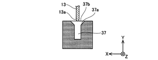
- a slope 13a may be provided at the corner of the tip of the rib 13.
- a chamfer 37a may be provided at the corner of the groove 37.
- the rib enters the groove means that the tip of the rib 13 reaches the position of the boundary 37b of the groove 37 as shown in FIG.
- the tip of the rib 13 can press the foreign matter 100 (see FIG. 6) into the groove 37 by reaching the boundary 37b. That is, the rib 13 prevents the foreign matter 100 from moving to a position connecting between adjacent cable terminals by reaching the boundary 37b.
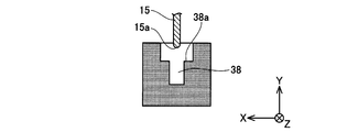
- the tip of the rib may further penetrate into the groove, as shown in FIGS. 8 and 9.
- a fillet 15a may be provided at the tip of the rib 15. Further, a step 38a may be provided at the corner of the groove 38.
- the tip of the rib 15 can easily enter the groove 38. Further, by providing the step 38a at the corner of the groove 38, the tip of the rib 15 can easily enter the groove 38, and the creepage distance between the adjacent bus bar ends can be lengthened.
- a fillet 17a may be provided at the tip of the slope of the rib 17. Further, a fillet 39a may be provided at a corner of the groove 39. Similar to the chamfer 37a and the step 38a shown in FIG. 7, by providing the fillet 39a at the corner of the groove 39, the tip of the rib 17 can easily enter the groove 39.
- the housing 4a provided in the power conversion device of the embodiment accommodates an inverter and a converter, but the housing is not limited to this, and the housing may accommodate a terminal block. In that case, electricity of the inverter or the like is provided.
- the device is arranged outside the housing.
- the rib of the service cover 10 provided in the power conversion device 4 of the embodiment is not in contact with the groove of the terminal block 30, the tip of the rib may be fitted into the groove.
Landscapes
- Connections Arranged To Contact A Plurality Of Conductors (AREA)
Abstract
本装置は、端子台を収容しているとともに開口が形成されている筐体と、筐体の外部から開口を通過して端子台に達している複数本のケーブルと、複数本のケーブルが通過している開口を覆っているサービスカバーを備えている。端子台には、複数本のバスバの各端部が隣接して配置されており、隣接している端部同士の間を延びる溝が形成されている。各ケーブルの端部は、ネジによって対応するバスバの端部に固定されている。サービスカバーには、開口を通過して溝内に入り込んでいるリブが形成されており、隣接する端部同士の間の短絡を規制する。
Description
本明細書は、端子台を収容しているとともに開口が形成されている筐体と、筐体の外部から開口を通過して端子台に達している複数本のケーブルを備えており、複数本のケーブルが通過している開口をサービスカバーで覆っている装置に関する。
筐体内に位置しているバスバと筐体外を延びているケーブルを接続するために、筐体内に端子台を設けるとともに筐体に開口を設ける技術が知られている。端子台にはバスバの端部が固定されており、ケーブルは筐体開口を通過する。バスバが固定されている端子台にケーブルの端部を固定することによって、バスバとケーブルを接続する。複数本のケーブルのそれぞれを、対応するバスバに接続する場合、複数本のバスバの端部同士が隣接する関係で端子台に固定しておく。
装置の小型化を図るためには、隣接するバスバの端部同士の間隔を狭くすることが求められる。しかしながら、狭くすると、筐体内に侵入した異物によって隣接するバスバの端部同士が短絡する可能性が高まる。
特開平10-172635号公報(文献1)に開示されている装置(文献1では雷サージ保護装置と称している)は、端子台とサービスカバー(文献1ではケース蓋と称している)を備えている。文献1の端子台は、隣接するバスバの端部(文献1では、接続端子と称している)同士の間からサービスカバー側に向けて延びている突出部を備えており、その突出部の先端面に凹部が形成されている。文献1のサービスカバーは、前記凹部にかみ合う突出部を備えている。文献1の装置では、端子台側の突出部(正確にはその先端に形成されている凹部)と、サービスカバー側の突出部がかみ合うことで隣接するバスバの端部同士の間を遮断している。
ケーブルの端部をボルトまたはナット等のネジによってバスバの端部に固定する場合、のネジを締結するためのワークスペースが必要となる。文献1の端子台では、隣接するバスバの端部同士の間から立設する突出部を備えている。そのため、文献1の端子台では、バスバの端部と突出部の間にワークスペースを確保する必要があり、隣接するバスバの端部同士の間隔を広くとる必要がある。本明細書は、端子台のサイズを小さくしつつ、隣接するバスバの端部同士の短絡に対策した装置を開示する。
本明細書が開示する装置は、端子台を収容しているとともに開口が形成されている筐体と、筐体の外部から開口を通過して端子台に達している複数本のケーブルと、複数本のケーブルが通過している開口を覆っているサービスカバーを備えている。端子台には、複数本のバスバの各端部が隣接して配置されているとともに隣接している端部同士の間を延びる溝が形成されている。各ケーブルの端部は、ネジによって対応するバスバの端部に固定されている。本明細書で開示する装置のサービスカバーには、開口を通過して溝内に入り込んでいるリブが形成されている。
上述した装置では、ケーブルの端部をネジによって端子台に固定した後に、サービスカバーをケーブルのコネクタに固定する。ケーブルを端子台に固定する段階では、隣接するバスバの端部同士の間を溝が伸びており、端部同士の間に突出ないし立設するものがない状態で固定作業を進めることができる。ワークスペースが遮られないために、隣接する端部同士の間隔を狭くすることができる。また、ケーブルと端子台を固定した後では、サービスカバーのリブが、隣接しているバスバの端部同士の間の溝に入り込む。リブと溝が、隣接するバスバの端部同士の間を遮る。隣接するバスバの端部同士を短絡させる異物が筐体内に侵入しても、リブと溝によって、その異物が隣接する端部間を短絡させる位置に移動することを阻止する。
また上述した装置では、サービスカバーが筐体に固定された状態で、リブと溝が非接触であってもよい。これにより、サービスカバーと溝の内面が干渉しない。その結果、サービスカバーを筐体に確実に固定することができる。
本明細書が開示する技術の詳細とさらなる改良は以下の「実施例」にて説明する。
図面を参照して実施例の装置の一例である電力変換装置について説明する。図1に実施例の電力変換装置4を備える機電一体装置2の側面図を示す。機電一体装置2は、不図示の電気自動車のフロントコンパートメントに配置される。機電一体装置2は、電力変換装置4と、トランスアクスル6を備えている。電力変換装置4は、トランスアクスル6の上面に配置されている。トランスアクスル6は、電気自動車を走行させるモータ9と動力分配装置8とディファレンシャルギア7を備えている。モータ9は、三相交流モータである。トランスアクスル6は、2個の三相交流モータを備えているが、図1では図示を省略している。以下では、一方のモータ9に着目して説明する。
電力変換装置4は、筐体4a内に不図示のインバータとコンバータを備えている。電力変換装置4は、筐体4a内のコンバータによって電気自動車の不図示のメインバッテリの直流電力を昇圧するとともに、筐体4a内のインバータによって昇圧した直流電力をトランスアクスル6のモータ9の駆動に適した交流電力に変換する。
電力変換装置4が変換した交流電力をトランスアクスル6に送るため、電力変換装置4とトランスアクスル6は複数のケーブル20で接続されている。図1に示されるように、電力変換装置4とトランスアクスル6は6本のケーブル20で接続されている。モータ9は、三相交流モータであるため、V相、U相、W相の3個の入力端子(不図示)を有している。電力変換装置4は、トランスアクスル6の2個のモータに対して、6本のケーブル20で2組の三相交流を伝送する。
電力変換装置4は、筐体4aのY軸方向正側(すなわち、紙面手前側)の側面にサービスカバー10を備えている。サービスカバー10は、電力変換装置4の側面のトランスアクスル6側かつX軸方向正側(すなわち、紙面左側)に固定されている。詳細は後述するが、サービスカバーは、ケーブル20を電力変換装置4に接続した後にその開口を覆う蓋である。サービスカバー10は、X軸方向の両端の取付座を貫通する2個のボルト16によって電力変換装置4の筐体4aに固定されている。また、サービスカバー10と筐体4aの間には、ケーブルモジュール12が4個のボルト14によって固定されている。
図2~図4を参照して、サービスカバー10を筐体4aに固定する構造について説明する。図4に示されるように、筐体4aのY軸方向正側の側面には、X軸方向に延びている開口40が設けられている。筐体4aは、内部に端子台30を収容している。端子台30のY軸方向正側の面には、6本のバスバ端部30a~30fがX軸方向に隣接して配置されている。図3に示されるように、6本のバスバ端部30a~30fには、X軸方向に隣接した6本のケーブル端子26a~26fが6本のボルト28a~28fによって固定されている。6本のボルト28a~28fは、開口40(図4参照)を通過して端子台30に締結される。図2に示されるように、サービスカバー10は、6本のボルト28a~28fを締結したあとに、開口40を覆うカバーである。また、機電一体装置2(図1参照)のメンテナンス時には、サービスカバー10を取り外して、開口40内の状態を確認する。
図2を参照してサービスカバー10の形状について説明する。サービスカバー10は、X軸方向に延びている矩形形状を有している。サービスカバー10は、カバー本体10aと、取付座10bを備えている。カバー本体10aの中央部には、ネジ18が貫通する座面と、ボス19が貫通する座面が形成されている。詳細は図6を参照して後述するが、カバー本体10aには、Y軸方向負側にインナーカバー11が固定されている。ネジ18によって、カバー本体10aとインナーカバー11(図6参照)が固定される。ボス19によって、カバー本体10aに対するインナーカバー11の位置が固定される。なお、カバー本体10aは典型的には板金部品である。インナーカバー11は典型的には樹脂部品である。
取付座10bは、カバー本体10aのX軸方向の両端の立壁からX軸方向に延びるように形成されている。取付座10bのそれぞれは、ケーブルモジュール12にY軸方向正側から重なるように配置されている。図3に示されるように、ケーブルモジュール12の取付座10bが重なる部位には、ナット12cが設けられている。ボルト16は、ケーブルモジュール12のナット12cに螺合する。ケーブルモジュール12は、4本のボルト14によって筐体4aに固定されている。このように、サービスカバー10は、ケーブルモジュール12を介して筐体4aに固定される。カバー本体10aは、取付座10bと接続する立壁を有している。立壁は、カバー本体10aのZ軸方向負側(すなわち、紙面下側)には形成されていない。カバー本体10aのZ軸方向負側は、開放されている。カバー本体10aのトランスアクスル6と対向する部位は、開放されている。
サービスカバー10のトランスアクスル6と対向する部位には、ケーブル20a~20fが配策されている。ケーブル20a~20fは、開放されているカバー本体10aのZ軸方向負側から延びており、Y軸方向負側に屈曲している。ケーブル20a~20fは、Y軸方向負側に屈曲してY軸方向負側に延びており、その先端は、それぞれ、トランスアクスル6内のモータ(不図示)に接続される。
また、ケーブル20a~20fはY軸方向正側から磁気シールド22に覆われている。磁気シールド22は、ケーブル20a~20fに沿ってY軸方向負側に湾曲している。磁気シールド22は、ケーブル20a~20fから発生する電磁波が拡散するのを防止する。
図3を参照してケーブルモジュール12の形状について説明する。ケーブルモジュール12は、プレート部12aと、フランジ部12bと、6本のケーブル20a~20fを備えている。プレート部12aは、平板状の板金であり、四隅にボルト14が貫通する貫通孔を備えている。フランジ部12bは、プレート部12aの中央の開口の縁部からY軸正方向に延びている樹脂部品であり、Z軸方向正側に5本の三角リブを有している。6本のケーブル20a~20fは、端子台30側の端部にケーブル端子26a~26fを備えている。ケーブル端子26a~26fは、導体の平板で形成されている。ケーブル端子26a~26fは、フランジ部12bの内側でZ軸向正側にのび、Y軸方向負側に屈曲して、さらにZ軸方向正側に屈曲している。ケーブル端子26a~26fは、対応するバスバ端部30a~30f(図4参照)と接続する。すなわち、ケーブル20a~20fは、対応するバスバ端部30a~30f(図4参照)と接続する。このように、ケーブルモジュール12のケーブル20a~20fは、開口40(図4参照)を通過する。開口40を通過したケーブル20a~20fのケーブル端子26a~26fは、対応するバスバ端部30a~30fのそれぞれに固定される。
プレート部12aと、フランジ部12bと、6本のケーブル20a~20fは、同一型内で一体に成型される。図4に示す筐体4aにケーブルモジュール12がY軸方向正側から配置される。プレート部12aは、X軸方向の両端部に筐体4aの位置決めボス4b、4cを挿通させる貫通孔を有している。位置決めボス4b、4cがプレート部12aの貫通孔を挿通することで、筐体4aに対するケーブルモジュール12のX軸およびZ軸方向の位置が固定される。これにより、図4に示される筐体4aの筐体ボルト穴14a~14dと、プレート部12aの貫通孔が対向する。4本のボルト14がプレート部12aの4隅の貫通孔を貫通して、筐体ボルト穴14a~14dと螺合することで、ケーブルモジュール12が筐体4aに固定される。
ケーブルモジュール12が筐体4aに固定されると、ケーブル20aのケーブル端子26aは、対応するバスバ端部30aと重なる。ケーブル端子26aは、ボルト28aを貫通させる貫通孔を備えている。ケーブル端子26aとバスバ端部30aが重なった状態で、ボルト28aを対応する端子ボルト孔34a(図4参照)に螺合させる。このように、実施例の電力変換装置4は、ボルト28aによってケーブル端子26aと対応するバスバ端部30aを固定する。同様に、ケーブル端子26b~26fも、対応するボルトによって、対応するバスバ端部に固定される。
複数のケーブル端子26a~26fを対応するバスバ端部に固定した後、磁気シールド22が、Y軸方向正側からケーブルモジュール12に重なるように配置される。磁気シールド22のケーブルモジュール12側の端部は、シールド保持部22aに固定されている。シールド保持部22aは、X軸方向両端に位置するネジ24によってケーブルモジュール12に固定される。シールド保持部22aは、板金によって構成されている。図3には表現されていないが、シールド保持部22aの中央部は、Y軸方向に重なるように折り曲げられている。シールド保持部22aは、磁気シールド22を挟み込むことで保持している。図3には示されていないが、磁気シールド22のトランスアクスル6側の端部にも、磁気シールド22を挟み込むシールド保持部が設けられている。磁気シールド22のトランスアクスル6側の端部は、ケーブル20a~20fとトランスアクスル6の間に挟まれる。これにより、磁気シールド22は、ケーブル20a~20fに沿って湾曲する。
実施例の電力変換装置4(図1参照)は、端子台30に隣接して配置されているバスバ端部30a~30fに、対応するのケーブル端子26a~26fをボルト28a~28fによって固定している。電力変換装置4が作動すると、各バスバ端部および各ケーブルには、モータ9(図1参照)を駆動させるための高電圧が印加される。開口40から異物が混入して隣接する端子間を跨ぐように異物が接触すると、短絡して大電流が端子間に流れてしまうおそれがある。実施例の電力変換装置4では、5mm~10mmの長さの異物が混入した場合に、端子間を跨ぐおそれがある。そのため、サービスカバー10(図2参照)を外してメンテナンスする際に異物100が混入した場合には、目視による異物の発見は困難な場合がある。
図5を参照して、端子台30の備える溝32a~32eについて説明する。図5に示すように、隣接しているバスバ端部30aとバスバ端部30bの間には、溝32aがZ軸方向に延びている。すなわち、溝32aは、隣接しているバスバ端部同士の間を延びている。同様に、バスバ端部30bとバスバ端部30cの間には、溝32bがZ軸方向に延びている。他の溝32c~32eも、隣接するバスバ端部の間を延びている。
図6を参照して、端子台30が備える溝32b~32dと、ボルト28dをボルト穴34dに螺合させる際に必要となるワークスペースの位置関係について説明する。図6は、図5の中央に位置する2個のバスバ端部30c、30dの断面図である。図6に示されように、ボルト28dは、ケーブル端子26dとバスバ端部30dを貫通して、端子台30のボルト穴34dと螺合している。より詳細には、ボルト28dは、ケーブル端子26dとバスバ端部30dを貫通して、ボルト穴34dに設けられているインサートナット36dと螺合している。電力変換装置4(図1参照)を組み立てる際、作業者は、図3に示すケーブルモジュール12のフランジ部12bの開口からボルト28dを締結する。ボルト28dは、頭部をトルクレンチ(不図示)に嵌合させた状態でフランジ部12bの開口を通過する。トルクレンチのボルト28dの頭部と嵌合する部位は、ボルト28dの頭部の外径よりも大きい。図6では、ボルト28dを締結するために必要な空間をワークスペースWSで示している。ワークスペースWSは、端子台30等の寸法バラツキや、作業バラツキによって決定される、ボルト28dをボルト穴34dに締結する際に必要な空間である。
図6に示されるように、サービスカバー10のインナーカバー11は、端子台30の溝32cに向かって延びているリブ11cを備えている。リブ11cは、溝32cに入り込んでいる。図2を参照して説明したように、サービスカバー10は、筐体4aの開口40を塞ぐように筐体4aに固定されている。すなわち、リブ11cは、開口40を通過して溝32c内に入り込んでいる。同様に、インナーカバー11は、端子台30の溝32dに入り込んでいるリブ11dを備えている。リブ11cは、隣接するケーブル端子26c、26dの間を遮断している。このため、破線で示される異物100は、リブ11cによって端子台30の表面のリブ11cに押し付けられる。その結果、異物100は、隣接するケーブル端子26c、26dを跨ぐように付着しない。別言すれば、サービスカバー10が筐体4a(図2参照)固定された状態では、異物100は、電力変換装置4を短絡させない。
図6に示されるように、リブ11c、11dは、ワークスペースWS内に配置されている。このため、ボルト28dを締結する際に、リブ11c、11dの位置に、隣接するケーブル端子の間を遮断する壁は、設けることができない。本明細書が開示する電力変換装置4では、隣接するケーブル端子の間を遮断するリブが、サービスカバー10に設けられている。そのため、ボルト28dを締結する際に、リブ11c、11dは存在しない。そのため、電力変換装置4は、隣接するケーブル端子の間の距離を、小さくすることができる。すなわち、電力変換装置4は、端子台30のサイズを小さくすることができる。
本明細書が開示する電力変換装置4は、端子台30の隣接するバスバ端部同士の間に溝を設け、ボルトの締結後に筐体4aに固定されるサービスカバー10に、隣接するバスバ端部を遮断するリブを設けている。これにより、電力変換装置4は、異物による短絡を防止しつつ、端子台30のサイズを小さくする。また、隣接するバスバ端部同士の間を延びている溝は、バスバ端部同士の沿面距離を長くする。電力変換装置4は、溝によってバスバ端部同士の沿面距離を長くすることで、隣接する端子同士の短絡を防止することができる。
図7~図9を参照して、サービスカバー10(図6参照)が備えるリブの先端と、リブの先端が入り込む溝との関係について説明する。図7~図9は、リブの先端形状の変形例と、溝の形状の変形例を示す。
図7に示されるように、リブ13の先端の角部には、斜面13aが設けられてもよい。また、溝37の角部には、面取り37aが設けられてもよい。斜面13aや、面取り37aを設けることで、リブ13の先端が溝37に入り込みやすい。また、図7に示されるように、リブ13の先端は、溝37と非接触であってもよい。リブ13と溝37を非接触にすることで、リブ13の溝37に対する位置や、厚みがばらついても、リブ13と溝37は干渉しない。このため、サービスカバー10は、確実に筐体4aに固定される。
また、「リブが溝内に入り込む」とは、図7に示されるように、溝37の境界37bの位置にリブ13の先端が達することを言う。リブ13の先端は、境界37bに達することで異物100(図6参照)を溝37に押し付けることができる。すなわち、リブ13は、境界37bに達することで、異物100が隣接するケーブル端子の間を接続する位置に移動することを阻止する。しかしながら、リブの先端は、図8、図9に示されるように、溝内にさらに入り込んでもよい。
図8に示されるように、リブ15の先端にはフィレット15aが設けられてもよい。また、溝38の角部には、段差38aが設けられてもよい。リブ15の先端にフィレット15aを設けることで、リブ15の先端が溝38に入り込みやすい。また、溝38の角部に段差38aを設けることで、溝38にリブ15の先端が入り込みやすく、かつ、隣接するバスバ端部同士の沿面距離を長くすることができる。
図9に示されるように、リブ17の斜面の先端にフィレット17aが設けられてもよい。また、溝39の角部に、フィレット39aを設けてもよい。図7に示す面取り37a、段差38aと同様に、溝39の角部に、フィレット39aを設けることで、リブ17の先端が、溝39に入り込みやすい。
実施例の留意点を以下に述べる。実施例の電力変換装置が備えている筐体4aは、インバータおよびコンバータを収容しているが、これに限定されず、筐体は、端子台を収容すればよく、その場合、インバータ等の電気機器は筐体外部に配置される。
また、実施例の電力変換装置4が備えているサービスカバー10のリブは、端子台30の溝と非接触であるが、リブの先端が溝に嵌合してもよい。
以上、本発明の具体例を詳細に説明したが、これらは例示に過ぎず、請求の範囲を限定するものではない。請求の範囲に記載の技術には、以上に例示した具体例を様々に変形、変更したものが含まれる。本明細書または図面に説明した技術要素は、単独であるいは各種の組合せによって技術的有用性を発揮するものであり、出願時請求項記載の組合せに限定されるものではない。また、本明細書または図面に例示した技術は複数目的を同時に達成し得るものであり、そのうちの一つの目的を達成すること自体で技術的有用性を持つものである。
Claims (2)
- 端子台を収容しているとともに開口が形成されている筐体と、
前記筐体の外部から前記開口を通過して前記端子台に達している複数本のケーブルと、
前記複数本のケーブルが通過している前記開口を覆っているサービスカバーを備えており、
前記端子台には、複数本のバスバの各端部が隣接して配置されているとともに、隣接している端部同士の間を延びる溝が形成されており、
各ケーブルの端部は、ネジによって対応するバスバの端部に固定されており、
前記サービスカバーに、前記開口を通過して前記溝内に入り込んでいるリブが形成されていることを特徴とする装置。 - 前記サービスカバーが前記筐体に固定された状態で、前記リブと前記溝が非接触である請求項1に記載の装置。
Priority Applications (2)
| Application Number | Priority Date | Filing Date | Title |
|---|---|---|---|
| PCT/JP2019/043474 WO2021090398A1 (ja) | 2019-11-06 | 2019-11-06 | サービスカバーを備えている装置 |
| JP2021554464A JP7248145B2 (ja) | 2019-11-06 | 2019-11-06 | サービスカバーを備えている装置 |
Applications Claiming Priority (1)
| Application Number | Priority Date | Filing Date | Title |
|---|---|---|---|
| PCT/JP2019/043474 WO2021090398A1 (ja) | 2019-11-06 | 2019-11-06 | サービスカバーを備えている装置 |
Publications (1)
| Publication Number | Publication Date |
|---|---|
| WO2021090398A1 true WO2021090398A1 (ja) | 2021-05-14 |
Family
ID=75848841
Family Applications (1)
| Application Number | Title | Priority Date | Filing Date |
|---|---|---|---|
| PCT/JP2019/043474 WO2021090398A1 (ja) | 2019-11-06 | 2019-11-06 | サービスカバーを備えている装置 |
Country Status (2)
| Country | Link |
|---|---|
| JP (1) | JP7248145B2 (ja) |
| WO (1) | WO2021090398A1 (ja) |
Citations (5)
| Publication number | Priority date | Publication date | Assignee | Title |
|---|---|---|---|---|
| JPS63196569A (ja) * | 1987-02-03 | 1988-08-15 | バイエル・アクチエンゲゼルシヤフト | 光学活性2−ヒドロキシエチル−アゾール誘導体の製造方法 |
| JPH07336932A (ja) * | 1994-06-13 | 1995-12-22 | Fuji Electric Co Ltd | 端子箱 |
| JP2004328932A (ja) * | 2003-04-25 | 2004-11-18 | Toyota Motor Corp | 電動機ユニットおよび動力出力装置 |
| JP2009023456A (ja) * | 2007-07-18 | 2009-02-05 | Nsk Ltd | 電動パワーステアリング装置 |
| JP2017189095A (ja) * | 2016-04-04 | 2017-10-12 | ミネベアミツミ株式会社 | ステータ構造およびレゾルバ |
Family Cites Families (2)
| Publication number | Priority date | Publication date | Assignee | Title |
|---|---|---|---|---|
| JPS63196569U (ja) * | 1987-06-04 | 1988-12-19 | ||
| JP5650253B2 (ja) | 2013-01-15 | 2015-01-07 | トヨタ自動車株式会社 | パワーケーブルの接続構造 |
-
2019
- 2019-11-06 WO PCT/JP2019/043474 patent/WO2021090398A1/ja active Application Filing
- 2019-11-06 JP JP2021554464A patent/JP7248145B2/ja active Active
Patent Citations (5)
| Publication number | Priority date | Publication date | Assignee | Title |
|---|---|---|---|---|
| JPS63196569A (ja) * | 1987-02-03 | 1988-08-15 | バイエル・アクチエンゲゼルシヤフト | 光学活性2−ヒドロキシエチル−アゾール誘導体の製造方法 |
| JPH07336932A (ja) * | 1994-06-13 | 1995-12-22 | Fuji Electric Co Ltd | 端子箱 |
| JP2004328932A (ja) * | 2003-04-25 | 2004-11-18 | Toyota Motor Corp | 電動機ユニットおよび動力出力装置 |
| JP2009023456A (ja) * | 2007-07-18 | 2009-02-05 | Nsk Ltd | 電動パワーステアリング装置 |
| JP2017189095A (ja) * | 2016-04-04 | 2017-10-12 | ミネベアミツミ株式会社 | ステータ構造およびレゾルバ |
Also Published As
| Publication number | Publication date |
|---|---|
| JPWO2021090398A1 (ja) | 2021-05-14 |
| JP7248145B2 (ja) | 2023-03-29 |
Similar Documents
| Publication | Publication Date | Title |
|---|---|---|
| CN107742976B (zh) | 滤波器和车辆 | |
| WO2013136618A1 (ja) | 高電圧用電気接続箱 | |
| JP2011167056A (ja) | 電力変換装置 | |
| US10660229B2 (en) | Electrical device and manufacturing method of the same | |
| EP3057216A1 (en) | Dc-dc converter device | |
| CN103928774A (zh) | 用于电力电缆的连接装置 | |
| US10490990B2 (en) | Apparatus for electrically connecting at least one electrical component to a first and second busbar | |
| US10447017B2 (en) | Electric storage device | |
| CN111095769A (zh) | 电力转换装置 | |
| JP5931778B2 (ja) | 電力変換モジュール結線用のバスバーアッセンブリ | |
| JP2014017900A (ja) | 電気自動車用のインバータ | |
| JP5360985B2 (ja) | 端子の接続構造 | |
| US20190150304A1 (en) | Power distribution board | |
| WO2021090398A1 (ja) | サービスカバーを備えている装置 | |
| JP4973617B2 (ja) | 車両用電気接続端子台および車両駆動用インバータ装置 | |
| JP5345030B2 (ja) | 端子の接続構造 | |
| JP4149352B2 (ja) | ジャンクションブロックの接続構造 | |
| JP2019204596A (ja) | 配線モジュール | |
| WO2021124831A1 (ja) | 電力変換装置およびモータ | |
| WO2005109582A1 (en) | Connector for cable eyes | |
| CN109546870B (zh) | 输出端子及变流器 | |
| JP2021197831A (ja) | 電気ユニット | |
| JP2020022235A (ja) | 電力変換装置及びバスバ | |
| JP7419963B2 (ja) | 電力変換装置 | |
| WO2023084998A1 (ja) | 電源装置 |
Legal Events
| Date | Code | Title | Description |
|---|---|---|---|
| 121 | Ep: the epo has been informed by wipo that ep was designated in this application |
Ref document number: 19951980 Country of ref document: EP Kind code of ref document: A1 |
|
| ENP | Entry into the national phase |
Ref document number: 2021554464 Country of ref document: JP Kind code of ref document: A |
|
| NENP | Non-entry into the national phase |
Ref country code: DE |
|
| 122 | Ep: pct application non-entry in european phase |
Ref document number: 19951980 Country of ref document: EP Kind code of ref document: A1 |