WO2021090380A1 - 遠心送風機及び空気調和機の室内機 - Google Patents
遠心送風機及び空気調和機の室内機 Download PDFInfo
- Publication number
- WO2021090380A1 WO2021090380A1 PCT/JP2019/043385 JP2019043385W WO2021090380A1 WO 2021090380 A1 WO2021090380 A1 WO 2021090380A1 JP 2019043385 W JP2019043385 W JP 2019043385W WO 2021090380 A1 WO2021090380 A1 WO 2021090380A1
- Authority
- WO
- WIPO (PCT)
- Prior art keywords
- main plate
- centrifugal blower
- hub
- fan motor
- cooling air
- Prior art date
- Legal status (The legal status is an assumption and is not a legal conclusion. Google has not performed a legal analysis and makes no representation as to the accuracy of the status listed.)
- Ceased
Links
Images



Classifications
-
- F—MECHANICAL ENGINEERING; LIGHTING; HEATING; WEAPONS; BLASTING
- F04—POSITIVE - DISPLACEMENT MACHINES FOR LIQUIDS; PUMPS FOR LIQUIDS OR ELASTIC FLUIDS
- F04D—NON-POSITIVE-DISPLACEMENT PUMPS
- F04D17/00—Radial-flow pumps, e.g. centrifugal pumps; Helico-centrifugal pumps
- F04D17/08—Centrifugal pumps
- F04D17/16—Centrifugal pumps for displacing without appreciable compression
-
- F—MECHANICAL ENGINEERING; LIGHTING; HEATING; WEAPONS; BLASTING
- F04—POSITIVE - DISPLACEMENT MACHINES FOR LIQUIDS; PUMPS FOR LIQUIDS OR ELASTIC FLUIDS
- F04D—NON-POSITIVE-DISPLACEMENT PUMPS
- F04D29/00—Details, component parts, or accessories
- F04D29/26—Rotors specially for elastic fluids
- F04D29/28—Rotors specially for elastic fluids for centrifugal or helico-centrifugal pumps for radial-flow or helico-centrifugal pumps
-
- F—MECHANICAL ENGINEERING; LIGHTING; HEATING; WEAPONS; BLASTING
- F04—POSITIVE - DISPLACEMENT MACHINES FOR LIQUIDS; PUMPS FOR LIQUIDS OR ELASTIC FLUIDS
- F04D—NON-POSITIVE-DISPLACEMENT PUMPS
- F04D29/00—Details, component parts, or accessories
- F04D29/58—Cooling; Heating; Diminishing heat transfer
Definitions
- the present invention relates to a centrifugal blower used for an indoor unit of an air conditioner and an indoor unit of an air conditioner.
- Ceiling-embedded air conditioners are generally equipped with a centrifugal blower as a blower.
- a centrifugal blower as a blower.
- the air in the room is sucked from the central portion of the decorative panel by the centrifugal blower and flows into the centrifugal blower.
- the indoor air that has flowed into the centrifugal blower is blown to a heat exchanger arranged around the centrifugal blower to become conditioned air of cold air or hot air, and is blown into the room from the outlet.
- Such a centrifugal blower includes a circular main plate, a shroud, a plurality of blades, a fan motor, and a hub.
- the shroud is arranged to face the main plate and has an annular shape.
- a plurality of wings are arranged between the shroud and the outer periphery of the main plate.
- the fan motor is arranged on the side opposite to the shroud of the main plate and drives the main plate to rotate.
- the hub is formed in the central part of the main plate.
- a cooling air outlet hole is formed near the center of the hub in order to cool the fan motor.
- Patent Document 1 a centrifuge having a deflection member at the opening edge of the cooling air outlet hole for adjusting the air blown from the cooling air outlet hole toward the blowing direction of the centrifugal blower. Blowers have been proposed.
- the deflection member has a convex shape with respect to the hub surface. Therefore, the suction air may be disturbed in the rotation direction of the centrifugal blower by this deflection member, and a rotation sound having a peak at a frequency that is an integral multiple of the rotation speed of the blower may be generated.
- the present invention has been made in view of the above circumstances, and an object of the present invention is to provide an indoor unit of a centrifugal blower and an air conditioner capable of suppressing the rotating noise of the air blown from the cooling air outlet hole.
- a main plate rotationally driven by a fan motor, an annular shroud arranged so as to face the main plate, and arranged between the main plate and the shroud.
- the main plate is provided with a plurality of blades, the main plate guides the air sucked into the shroud by the plurality of blades in the radial direction orthogonal to the rotation axis of the main plate, and the main plate is perpendicular to the radial direction.
- It has a hub having a vertical surface, and the vertical surface of the hub is provided with a plurality of cooling air outlet holes from which the cooling air that cools the fan motor is led out at predetermined intervals in the circumferential direction of the hub.
- the hub has a vertical plane perpendicular to the radial direction orthogonal to the rotation axis of the main plate.
- a cooling air outlet hole is provided on the vertical surface of the hub. The direction of the fan motor cooling air led out from the cooling air outlet hole is close to the direction of the main flow of air guided in the radial direction by the main plate. Therefore, it is possible to suppress the rotational noise generated when the fan motor cooling air merges with the mainstream of air.
- FIG. 1 is an explanatory view showing a left half cross section of a ceiling-embedded indoor unit 2 provided with the centrifugal blower 1 according to the embodiment.
- the ceiling-embedded indoor unit 2 is buried behind the ceiling.
- a rectangular decorative panel 3 is attached from the lower surface opening to the peripheral edge of the ceiling opening.
- the ceiling-embedded indoor unit 2 includes a centrifugal blower 1 and a heat exchanger 5 in a main body housing 4.
- the centrifugal blower 1 includes a bell mouth 7 and a fan motor 8.
- the centrifugal blower 1 is arranged in the center of the main body housing 4.
- the fan motor 8 is fixed to the center of the top surface of the main body housing 4.
- the center of the centrifugal blower 1 is coaxially attached to the rotating shaft 9 of the fan motor 8, and is rotationally driven by the fan motor 8.
- the bell mouth 7 is attached to the lower side of the centrifugal blower 1.
- the ceiling-embedded indoor unit 2 sucks air from the bell mouth 7 covered with the decorative panel 3 by the rotation of the centrifugal blower 1.
- the air sent to the outside of the centrifugal blower 1 in the radial direction passes through the heat exchanger 5 provided around the centrifugal blower 1.
- the air passing through the heat exchanger 5 exchanges heat with the refrigerant flowing in the heat exchanger 5.
- the heat-exchanged conditioned air is sent to the outside of the centrifugal blower 1 in the radial direction from the heat exchanger 5 of the ceiling-embedded indoor unit 2.
- the harmonized air is blown into the air-conditioned room through the air outlet 13 at the lower outer side in the main body housing 4 of the ceiling-embedded indoor unit 2.
- FIG. 2 is a perspective view showing the centrifugal blower 1 according to the embodiment.
- the centrifugal blower 1 includes a main plate 14, a shroud 10, and a plurality of blades 12.
- the main plate 14 has a circular shape, is fixed to the rotating shaft 9 of the fan motor 8, and is rotationally driven by the fan motor 8.
- the shroud 10 has an annular shape, is arranged so as to face the main plate 14, and has an air suction port 11 that opens in the circumferential direction about the rotation axis AA of the main plate 14.
- the plurality of wings 12 are arranged between the outer peripheral portion of the main plate 14 and the shroud 10 at intervals in the circumferential direction of the main plate 14.
- the main plate 14 guides the air sucked into the air suction port 11 of the shroud 10 by the plurality of blades 12 in the radial direction orthogonal to the rotation axis AA of the main plate 14.
- a cylindrical hub 21 is formed around the rotation shaft 9 at the center of the main plate 14.
- the hub 21 has a circumferential surface 22 parallel to the rotation axis AA of the main plate 14.
- the circumferential surface 22 is provided with a plurality of cooling air outlet holes 23 at predetermined intervals along the circumferential direction of the circumferential surface 22. Cooling air that cools the fan motor 8 is derived from the cooling air outlet hole 23.
- the number of cooling air outlet holes 23 is the same as the number of blades 12, and one cooling air outlet hole 23 is arranged between the blade 12 and the blade 12. As a result, the positional relationship between each blade 12 and the cooling air outlet hole 23 is unified, and the shape of the flow until the air blown out from the cooling air outlet hole 23 flows into the blade 12 is aligned. Therefore, it is possible to prevent the airflows blown out from the cooling air outlet hole 23 from colliding with each other and increasing the noise.
- FIG. 3 is a cross-sectional view showing the main plate 14 in the radial direction orthogonal to the rotation axis AA of the main plate 14 of the centrifugal blower 1 according to the embodiment, the cooling air outlet hole 23, and the hub 21.
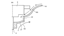
- FIG. 4 is a cross-sectional view showing the main plate 14, the circumferential surface 22, and the hub 21 in the radial direction orthogonal to the rotation axis AA direction of the main plate 14 of the centrifugal blower 1 according to the embodiment.
- the hub 21 has a circumferential surface 22 perpendicular to the radial direction orthogonal to the rotation axis AA direction of the main plate 14.
- the circumferential surface 22 is provided with cooling air lead-out holes 23 from which the cooling air that cools the fan motor 8 is led out at predetermined intervals in the circumferential direction.
- the fan motor cooling air RR that cools the fan motor 8 is blown out from the cooling air outlet hole 23. Since the cooling air outlet hole 23 is provided on the circumferential surface 22 perpendicular to the radial direction, the direction of the fan motor cooling air RR blown out from the cooling air outlet hole 23 is blown out in the radial direction by the centrifugal blower 1. It is close to the direction of the mainstream SS of the air. Therefore, when the fan motor cooling air RR merges with the mainstream air SS, the degree of interference of the fan motor cooling air RR with the mainstream air SS is reduced. As a result, deterioration of noise caused by the fan motor cooling air RR can be suppressed.
- the hub 21 since the hub 21 does not have a deflecting member having a convex shape on the surface in contact with the mainstream SS of air, the mainstream SS of air sucked by the convex portion is formed. It is possible to prevent the generation of rotating noise without being disturbed.
- FIG. 5 is a cross-sectional view showing a molding mold of the main plate 14 of the centrifugal blower 1 according to the embodiment.
- This molding die has a die 31 on the core side and a die 32 on the cavity side.
- the mold 31 on the core side is mainly formed to correspond to the shape of the hub 21 on the shroud 10 side.
- the mold 32 on the cavity side is mainly formed to correspond to the shape of the hub 21 on the fan motor 8 side.
- the mold 31 on the core side and the 32 on the cavity side can be opened in the axial direction, so that an increase in the number of parts of the apparatus and an increase in manufacturing cost are suppressed. can do.
- centrifugal blower 1 it is possible to suppress the rotation caused by the fan motor cooling air RR blown out from the cooling air outlet hole 23.
- the centrifugal blower 1 of the embodiment does not require a deflection member that adjusts the air blown out from the cooling air outlet hole 23 in the blowing direction of the centrifugal blower 1 as in the conventional case. Therefore, it is possible to suppress an increase in the weight of the centrifugal blower 1 and a deterioration in manufacturability.
- centrifugal blower 1 of the embodiment is applied to the ceiling-embedded indoor unit 2
- the embodiment is presented as an example and is not intended to limit the scope of the embodiment.
- the embodiment can be implemented in various other forms, and various omissions, replacements, and changes can be made without departing from the gist of the embodiment. These embodiments and variations thereof are included in the scope and gist of the embodiments.
Landscapes
- Engineering & Computer Science (AREA)
- Mechanical Engineering (AREA)
- General Engineering & Computer Science (AREA)
- Physics & Mathematics (AREA)
- Thermal Sciences (AREA)
- Air-Conditioning Room Units, And Self-Contained Units In General (AREA)
- Structures Of Non-Positive Displacement Pumps (AREA)
Priority Applications (2)
| Application Number | Priority Date | Filing Date | Title |
|---|---|---|---|
| JP2021554450A JPWO2021090380A1 (https=) | 2019-11-06 | 2019-11-06 | |
| PCT/JP2019/043385 WO2021090380A1 (ja) | 2019-11-06 | 2019-11-06 | 遠心送風機及び空気調和機の室内機 |
Applications Claiming Priority (1)
| Application Number | Priority Date | Filing Date | Title |
|---|---|---|---|
| PCT/JP2019/043385 WO2021090380A1 (ja) | 2019-11-06 | 2019-11-06 | 遠心送風機及び空気調和機の室内機 |
Publications (1)
| Publication Number | Publication Date |
|---|---|
| WO2021090380A1 true WO2021090380A1 (ja) | 2021-05-14 |
Family
ID=75848778
Family Applications (1)
| Application Number | Title | Priority Date | Filing Date |
|---|---|---|---|
| PCT/JP2019/043385 Ceased WO2021090380A1 (ja) | 2019-11-06 | 2019-11-06 | 遠心送風機及び空気調和機の室内機 |
Country Status (2)
| Country | Link |
|---|---|
| JP (1) | JPWO2021090380A1 (https=) |
| WO (1) | WO2021090380A1 (https=) |
Cited By (1)
| Publication number | Priority date | Publication date | Assignee | Title |
|---|---|---|---|---|
| CN115930298A (zh) * | 2022-05-23 | 2023-04-07 | 江苏普睿德环保工程有限公司 | 空气调节装置 |
Citations (4)
| Publication number | Priority date | Publication date | Assignee | Title |
|---|---|---|---|---|
| JPH10184591A (ja) * | 1996-12-20 | 1998-07-14 | Daikin Ind Ltd | ターボファン |
| JP2001248854A (ja) * | 2000-03-08 | 2001-09-14 | Daikin Ind Ltd | 空気調和機 |
| JP2005133710A (ja) * | 2003-10-07 | 2005-05-26 | Daikin Ind Ltd | 遠心送風機およびこれを用いた空気調和機 |
| JP2009221928A (ja) * | 2008-03-14 | 2009-10-01 | Calsonic Kansei Corp | シロッコファン及びその製造方法 |
-
2019
- 2019-11-06 JP JP2021554450A patent/JPWO2021090380A1/ja active Pending
- 2019-11-06 WO PCT/JP2019/043385 patent/WO2021090380A1/ja not_active Ceased
Patent Citations (4)
| Publication number | Priority date | Publication date | Assignee | Title |
|---|---|---|---|---|
| JPH10184591A (ja) * | 1996-12-20 | 1998-07-14 | Daikin Ind Ltd | ターボファン |
| JP2001248854A (ja) * | 2000-03-08 | 2001-09-14 | Daikin Ind Ltd | 空気調和機 |
| JP2005133710A (ja) * | 2003-10-07 | 2005-05-26 | Daikin Ind Ltd | 遠心送風機およびこれを用いた空気調和機 |
| JP2009221928A (ja) * | 2008-03-14 | 2009-10-01 | Calsonic Kansei Corp | シロッコファン及びその製造方法 |
Cited By (1)
| Publication number | Priority date | Publication date | Assignee | Title |
|---|---|---|---|---|
| CN115930298A (zh) * | 2022-05-23 | 2023-04-07 | 江苏普睿德环保工程有限公司 | 空气调节装置 |
Also Published As
| Publication number | Publication date |
|---|---|
| JPWO2021090380A1 (https=) | 2021-05-14 |
Similar Documents
| Publication | Publication Date | Title |
|---|---|---|
| AU2016304621B2 (en) | Fan and air-conditioning device | |
| WO2021090380A1 (ja) | 遠心送風機及び空気調和機の室内機 | |
| WO2020008519A1 (ja) | 多翼送風機及び空気調和装置 | |
| JP6524243B2 (ja) | 空気調和機の室外機 | |
| WO2023047849A1 (ja) | 天井埋込型空調 | |
| AU2017410135A1 (en) | Propeller fan and outdoor unit for air-conditioning apparatus | |
| JP4872997B2 (ja) | 送風機及び該送風機を備えた空気調和機 | |
| JP5574841B2 (ja) | ターボファンおよびそれを用いた空気調和機 | |
| JP2001295788A (ja) | ファンモータ一体型送風機 | |
| JP2003097488A (ja) | 遠心送風機及び空気調和機 | |
| WO2019163450A1 (ja) | ターボファン、及び空気調和機の室内機 | |
| JP5076324B2 (ja) | 遠心ファン | |
| TW201910693A (zh) | 空氣調節機 | |
| JP2009250112A (ja) | 遠心送風機の羽根車 | |
| JP7749130B2 (ja) | 遠心送風機および換気扇 | |
| JPWO2018096658A1 (ja) | 送風機、室外機及び冷凍サイクル装置 | |
| AU2022248081B2 (en) | Blower and indoor unit | |
| JP2024112574A (ja) | 送風機 | |
| JPWO2021090380A5 (https=) | ||
| CN112049816B (zh) | 离心风轮和具有其的空气处理设备 | |
| JP6692456B2 (ja) | プロペラファン及び空気調和装置の室外機 | |
| TH2401004187A (th) | หน่วยภายในอาคาร และเครื่องปรับอากาศ | |
| JPH11159975A (ja) | 遠心式送風手段を用いた熱交換器 | |
| WO2025088698A1 (ja) | 遠心送風機およびこれを備えた空気調和装置 | |
| WO2022201218A1 (ja) | 羽根車及び多翼送風機 |
Legal Events
| Date | Code | Title | Description |
|---|---|---|---|
| 121 | Ep: the epo has been informed by wipo that ep was designated in this application |
Ref document number: 19951977 Country of ref document: EP Kind code of ref document: A1 |
|
| ENP | Entry into the national phase |
Ref document number: 2021554450 Country of ref document: JP Kind code of ref document: A |
|
| NENP | Non-entry into the national phase |
Ref country code: DE |
|
| 122 | Ep: pct application non-entry in european phase |
Ref document number: 19951977 Country of ref document: EP Kind code of ref document: A1 |