WO2021085287A1 - Dispositif d'affichage d'image - Google Patents
Dispositif d'affichage d'image Download PDFInfo
- Publication number
- WO2021085287A1 WO2021085287A1 PCT/JP2020/039677 JP2020039677W WO2021085287A1 WO 2021085287 A1 WO2021085287 A1 WO 2021085287A1 JP 2020039677 W JP2020039677 W JP 2020039677W WO 2021085287 A1 WO2021085287 A1 WO 2021085287A1
- Authority
- WO
- WIPO (PCT)
- Prior art keywords
- image
- display
- virtual image
- viewpoint
- display device
- Prior art date
Links
- 230000003287 optical effect Effects 0.000 claims description 26
- 238000009792 diffusion process Methods 0.000 claims description 16
- 230000033001 locomotion Effects 0.000 claims description 13
- 230000004888 barrier function Effects 0.000 claims description 7
- 230000004044 response Effects 0.000 claims description 2
- 238000000034 method Methods 0.000 description 28
- 238000010586 diagram Methods 0.000 description 27
- 230000008859 change Effects 0.000 description 9
- 230000000694 effects Effects 0.000 description 7
- 230000005540 biological transmission Effects 0.000 description 6
- 230000004075 alteration Effects 0.000 description 5
- 230000007423 decrease Effects 0.000 description 3
- 235000002566 Capsicum Nutrition 0.000 description 2
- 125000002066 L-histidyl group Chemical group [H]N1C([H])=NC(C([H])([H])[C@](C(=O)[*])([H])N([H])[H])=C1[H] 0.000 description 2
- 239000006002 Pepper Substances 0.000 description 2
- 241000722363 Piper Species 0.000 description 2
- 235000016761 Piper aduncum Nutrition 0.000 description 2
- 235000017804 Piper guineense Nutrition 0.000 description 2
- 235000008184 Piper nigrum Nutrition 0.000 description 2
- 238000006243 chemical reaction Methods 0.000 description 2
- 230000000052 comparative effect Effects 0.000 description 2
- 239000006185 dispersion Substances 0.000 description 2
- 210000000887 face Anatomy 0.000 description 2
- 230000001771 impaired effect Effects 0.000 description 2
- 238000013459 approach Methods 0.000 description 1
- 239000002131 composite material Substances 0.000 description 1
- 239000011521 glass Substances 0.000 description 1
- 239000004973 liquid crystal related substance Substances 0.000 description 1
- 230000001151 other effect Effects 0.000 description 1
Images


Classifications
-
- H—ELECTRICITY
- H04—ELECTRIC COMMUNICATION TECHNIQUE
- H04N—PICTORIAL COMMUNICATION, e.g. TELEVISION
- H04N13/00—Stereoscopic video systems; Multi-view video systems; Details thereof
- H04N13/30—Image reproducers
- H04N13/349—Multi-view displays for displaying three or more geometrical viewpoints without viewer tracking
- H04N13/351—Multi-view displays for displaying three or more geometrical viewpoints without viewer tracking for displaying simultaneously
-
- H—ELECTRICITY
- H04—ELECTRIC COMMUNICATION TECHNIQUE
- H04N—PICTORIAL COMMUNICATION, e.g. TELEVISION
- H04N13/00—Stereoscopic video systems; Multi-view video systems; Details thereof
- H04N13/30—Image reproducers
- H04N13/388—Volumetric displays, i.e. systems where the image is built up from picture elements distributed through a volume
- H04N13/393—Volumetric displays, i.e. systems where the image is built up from picture elements distributed through a volume the volume being generated by a moving, e.g. vibrating or rotating, surface
-
- H—ELECTRICITY
- H04—ELECTRIC COMMUNICATION TECHNIQUE
- H04N—PICTORIAL COMMUNICATION, e.g. TELEVISION
- H04N13/00—Stereoscopic video systems; Multi-view video systems; Details thereof
- H04N13/30—Image reproducers
- H04N13/302—Image reproducers for viewing without the aid of special glasses, i.e. using autostereoscopic displays
- H04N13/322—Image reproducers for viewing without the aid of special glasses, i.e. using autostereoscopic displays using varifocal lenses or mirrors
-
- G—PHYSICS
- G02—OPTICS
- G02B—OPTICAL ELEMENTS, SYSTEMS OR APPARATUS
- G02B30/00—Optical systems or apparatus for producing three-dimensional [3D] effects, e.g. stereoscopic images
-
- G—PHYSICS
- G02—OPTICS
- G02B—OPTICAL ELEMENTS, SYSTEMS OR APPARATUS
- G02B30/00—Optical systems or apparatus for producing three-dimensional [3D] effects, e.g. stereoscopic images
- G02B30/20—Optical systems or apparatus for producing three-dimensional [3D] effects, e.g. stereoscopic images by providing first and second parallax images to an observer's left and right eyes
- G02B30/26—Optical systems or apparatus for producing three-dimensional [3D] effects, e.g. stereoscopic images by providing first and second parallax images to an observer's left and right eyes of the autostereoscopic type
-
- G—PHYSICS
- G02—OPTICS
- G02B—OPTICAL ELEMENTS, SYSTEMS OR APPARATUS
- G02B30/00—Optical systems or apparatus for producing three-dimensional [3D] effects, e.g. stereoscopic images
- G02B30/20—Optical systems or apparatus for producing three-dimensional [3D] effects, e.g. stereoscopic images by providing first and second parallax images to an observer's left and right eyes
- G02B30/34—Stereoscopes providing a stereoscopic pair of separated images corresponding to parallactically displaced views of the same object, e.g. 3D slide viewers
- G02B30/35—Stereoscopes providing a stereoscopic pair of separated images corresponding to parallactically displaced views of the same object, e.g. 3D slide viewers using reflective optical elements in the optical path between the images and the observer
-
- G—PHYSICS
- G02—OPTICS
- G02B—OPTICAL ELEMENTS, SYSTEMS OR APPARATUS
- G02B30/00—Optical systems or apparatus for producing three-dimensional [3D] effects, e.g. stereoscopic images
- G02B30/50—Optical systems or apparatus for producing three-dimensional [3D] effects, e.g. stereoscopic images the image being built up from image elements distributed over a 3D volume, e.g. voxels
- G02B30/54—Optical systems or apparatus for producing three-dimensional [3D] effects, e.g. stereoscopic images the image being built up from image elements distributed over a 3D volume, e.g. voxels the 3D volume being generated by moving a 2D surface, e.g. by vibrating or rotating the 2D surface
-
- G—PHYSICS
- G02—OPTICS
- G02B—OPTICAL ELEMENTS, SYSTEMS OR APPARATUS
- G02B30/00—Optical systems or apparatus for producing three-dimensional [3D] effects, e.g. stereoscopic images
- G02B30/50—Optical systems or apparatus for producing three-dimensional [3D] effects, e.g. stereoscopic images the image being built up from image elements distributed over a 3D volume, e.g. voxels
- G02B30/56—Optical systems or apparatus for producing three-dimensional [3D] effects, e.g. stereoscopic images the image being built up from image elements distributed over a 3D volume, e.g. voxels by projecting aerial or floating images
-
- G—PHYSICS
- G02—OPTICS
- G02B—OPTICAL ELEMENTS, SYSTEMS OR APPARATUS
- G02B5/00—Optical elements other than lenses
- G02B5/18—Diffraction gratings
-
- G—PHYSICS
- G02—OPTICS
- G02B—OPTICAL ELEMENTS, SYSTEMS OR APPARATUS
- G02B5/00—Optical elements other than lenses
- G02B5/32—Holograms used as optical elements
-
- G—PHYSICS
- G03—PHOTOGRAPHY; CINEMATOGRAPHY; ANALOGOUS TECHNIQUES USING WAVES OTHER THAN OPTICAL WAVES; ELECTROGRAPHY; HOLOGRAPHY
- G03B—APPARATUS OR ARRANGEMENTS FOR TAKING PHOTOGRAPHS OR FOR PROJECTING OR VIEWING THEM; APPARATUS OR ARRANGEMENTS EMPLOYING ANALOGOUS TECHNIQUES USING WAVES OTHER THAN OPTICAL WAVES; ACCESSORIES THEREFOR
- G03B21/00—Projectors or projection-type viewers; Accessories therefor
- G03B21/54—Accessories
- G03B21/56—Projection screens
- G03B21/60—Projection screens characterised by the nature of the surface
- G03B21/602—Lenticular screens
-
- G—PHYSICS
- G03—PHOTOGRAPHY; CINEMATOGRAPHY; ANALOGOUS TECHNIQUES USING WAVES OTHER THAN OPTICAL WAVES; ELECTROGRAPHY; HOLOGRAPHY
- G03B—APPARATUS OR ARRANGEMENTS FOR TAKING PHOTOGRAPHS OR FOR PROJECTING OR VIEWING THEM; APPARATUS OR ARRANGEMENTS EMPLOYING ANALOGOUS TECHNIQUES USING WAVES OTHER THAN OPTICAL WAVES; ACCESSORIES THEREFOR
- G03B35/00—Stereoscopic photography
- G03B35/18—Stereoscopic photography by simultaneous viewing
- G03B35/20—Stereoscopic photography by simultaneous viewing using two or more projectors
-
- G—PHYSICS
- G03—PHOTOGRAPHY; CINEMATOGRAPHY; ANALOGOUS TECHNIQUES USING WAVES OTHER THAN OPTICAL WAVES; ELECTROGRAPHY; HOLOGRAPHY
- G03B—APPARATUS OR ARRANGEMENTS FOR TAKING PHOTOGRAPHS OR FOR PROJECTING OR VIEWING THEM; APPARATUS OR ARRANGEMENTS EMPLOYING ANALOGOUS TECHNIQUES USING WAVES OTHER THAN OPTICAL WAVES; ACCESSORIES THEREFOR
- G03B35/00—Stereoscopic photography
- G03B35/18—Stereoscopic photography by simultaneous viewing
- G03B35/24—Stereoscopic photography by simultaneous viewing using apertured or refractive resolving means on screens or between screen and eye
-
- G—PHYSICS
- G03—PHOTOGRAPHY; CINEMATOGRAPHY; ANALOGOUS TECHNIQUES USING WAVES OTHER THAN OPTICAL WAVES; ELECTROGRAPHY; HOLOGRAPHY
- G03H—HOLOGRAPHIC PROCESSES OR APPARATUS
- G03H1/00—Holographic processes or apparatus using light, infrared or ultraviolet waves for obtaining holograms or for obtaining an image from them; Details peculiar thereto
-
- H—ELECTRICITY
- H04—ELECTRIC COMMUNICATION TECHNIQUE
- H04N—PICTORIAL COMMUNICATION, e.g. TELEVISION
- H04N13/00—Stereoscopic video systems; Multi-view video systems; Details thereof
- H04N13/30—Image reproducers
- H04N13/302—Image reproducers for viewing without the aid of special glasses, i.e. using autostereoscopic displays
-
- H—ELECTRICITY
- H04—ELECTRIC COMMUNICATION TECHNIQUE
- H04N—PICTORIAL COMMUNICATION, e.g. TELEVISION
- H04N13/00—Stereoscopic video systems; Multi-view video systems; Details thereof
- H04N13/30—Image reproducers
- H04N13/346—Image reproducers using prisms or semi-transparent mirrors
-
- H—ELECTRICITY
- H04—ELECTRIC COMMUNICATION TECHNIQUE
- H04N—PICTORIAL COMMUNICATION, e.g. TELEVISION
- H04N13/00—Stereoscopic video systems; Multi-view video systems; Details thereof
- H04N13/30—Image reproducers
- H04N13/363—Image reproducers using image projection screens
-
- H—ELECTRICITY
- H04—ELECTRIC COMMUNICATION TECHNIQUE
- H04N—PICTORIAL COMMUNICATION, e.g. TELEVISION
- H04N13/00—Stereoscopic video systems; Multi-view video systems; Details thereof
- H04N13/30—Image reproducers
- H04N13/366—Image reproducers using viewer tracking
-
- H—ELECTRICITY
- H04—ELECTRIC COMMUNICATION TECHNIQUE
- H04N—PICTORIAL COMMUNICATION, e.g. TELEVISION
- H04N13/00—Stereoscopic video systems; Multi-view video systems; Details thereof
- H04N13/30—Image reproducers
- H04N13/388—Volumetric displays, i.e. systems where the image is built up from picture elements distributed through a volume
- H04N13/395—Volumetric displays, i.e. systems where the image is built up from picture elements distributed through a volume with depth sampling, i.e. the volume being constructed from a stack or sequence of 2D image planes
-
- G—PHYSICS
- G03—PHOTOGRAPHY; CINEMATOGRAPHY; ANALOGOUS TECHNIQUES USING WAVES OTHER THAN OPTICAL WAVES; ELECTROGRAPHY; HOLOGRAPHY
- G03B—APPARATUS OR ARRANGEMENTS FOR TAKING PHOTOGRAPHS OR FOR PROJECTING OR VIEWING THEM; APPARATUS OR ARRANGEMENTS EMPLOYING ANALOGOUS TECHNIQUES USING WAVES OTHER THAN OPTICAL WAVES; ACCESSORIES THEREFOR
- G03B21/00—Projectors or projection-type viewers; Accessories therefor
- G03B21/54—Accessories
- G03B21/56—Projection screens
-
- G—PHYSICS
- G03—PHOTOGRAPHY; CINEMATOGRAPHY; ANALOGOUS TECHNIQUES USING WAVES OTHER THAN OPTICAL WAVES; ELECTROGRAPHY; HOLOGRAPHY
- G03H—HOLOGRAPHIC PROCESSES OR APPARATUS
- G03H1/00—Holographic processes or apparatus using light, infrared or ultraviolet waves for obtaining holograms or for obtaining an image from them; Details peculiar thereto
- G03H1/22—Processes or apparatus for obtaining an optical image from holograms
- G03H1/2249—Holobject properties
- G03H2001/2284—Superimposing the holobject with other visual information
Definitions
- This technology relates to an image display device applicable to stereoscopic display.
- Patent Document 1 describes a stereoscopic image display device that displays a stereoscopic image using a polygonal pyramid-shaped mirror.
- a polygonal pyramid-shaped mirror is arranged on a flat panel display with its apex side as a bottom surface.
- frame images of the same object viewed from different positions corresponding to each surface of the mirror are displayed.
- the purpose of this technology is to provide an image display device capable of realizing a stereoscopic display with a high sense of reality.
- the image display device includes one or more virtual image screens, a display unit, and a display control unit.
- the one or more virtual image screens are arranged so as to cover at least a part around a predetermined axis, display a virtual image of the projected image with the predetermined axis as a reference, and are transparent.
- the display unit displays a plurality of viewpoint images that are images of display objects viewed from different directions, and projects the displayed plurality of viewpoint images on each of the one or more virtual image screens. Has one or more display surfaces.
- the display control unit is visible from a second direction from the observation point toward the predetermined axis with respect to a first direction in which the display surface is viewed from the observation point around the virtual image screen via the virtual image screen.
- the viewpoint image which is a virtual image of the display target, is displayed.
- one or more transparent virtual image screens are arranged so as to cover at least a part around a predetermined axis. Further, one or more display surfaces for displaying a plurality of viewpoint images to be displayed in different directions are provided. A plurality of viewpoint images are projected on each virtual image screen. At this time, in the direction in which the display surface is viewed from a certain observation point via the virtual image screen, a viewpoint image that is a virtual image of the display target that can be seen when a predetermined axis is viewed from the observation point is displayed. This makes it possible to realize a stereoscopic display with a high sense of reality.
- the plurality of viewpoint images may be images viewed from a direction in which the display target is shifted by a predetermined angle pitch.
- the display control unit may display the viewpoint image so that the virtual image of the display target is switched at the predetermined angle pitch when viewed from the observation point in accordance with the movement of the observation point.
- the virtual image screen may reflect the viewpoint image projected from the display surface to display the virtual image of the viewpoint image.
- the display control unit may display the viewpoint image, which is a mirror-inverted image of the display target viewed from the second direction, in the first direction.
- the virtual image screen may display a virtual image of the viewpoint image through the viewpoint image projected from the display surface.
- the display control unit may display the viewpoint image of the display target viewed from the second direction in the first direction.
- the one or more virtual image screens may include a plurality of virtual image screens and form a multi-faceted screen with the predetermined axis as a reference.
- the virtual image screen may be either a diffractive optical element or a half mirror.
- the virtual image screen may be either a reflective holographic optical element or a transmissive holographic optical element.
- the one or more virtual image screens may be arranged so as to cover the entire circumference of the predetermined axis.
- the one or more display surfaces may be arranged so as not to block the virtual image displayed by the one or more virtual image screens.
- the one or more display surfaces include a plurality of display surfaces, and a multi-sided display may be configured with the predetermined axis as a reference.
- the virtual images of the plurality of viewpoint images may be displayed so that the center lines of the virtual image planes overlap each other.
- the virtual images of the plurality of viewpoint images may be displayed so that a part of the virtual image planes overlap each other. May be displayed so as to be in contact with each other.
- At least one of the virtual image screen and the display surface may have a curved surface shape.
- the display surface may be an image display surface of an anisotropic diffusion screen.
- the display unit may have a plurality of projection units that project an image onto the anisotropic diffusion screen from different directions.
- the display surface may be an image display surface of a direct-view stereoscopic display.
- the stereoscopic display may display the plurality of viewpoint images by any one of a lenticular lens system, a lens array system, and a parallax barrier system.
- FIG. 1 It is a schematic diagram which shows the structural example of the image display device which concerns on 2nd Embodiment. It is sectional drawing of the image display apparatus shown in FIG. It is a top view of the image display device shown in FIG. It is a schematic diagram which shows an example of the divided projection. It is a schematic diagram which shows the example of the display position of a virtual image in an image display device. It is a schematic diagram which shows the other configuration example of an image display device. It is a schematic diagram which shows the structural example of the image display device which concerns on 3rd Embodiment. It is a side view of the image display device shown in FIG. It is a top view of the image display device shown in FIG.
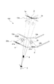
- FIG. 1 is a schematic diagram showing a basic configuration of an image display device according to a first embodiment of the present technology.
- 1A and 1B are a side view and a top view of the image display device 100.
- the image display device 100 is a device that three-dimensionally displays the virtual image 1 to be displayed to the users around the device.
- images (virtual images 1) of viewing objects viewed from various viewpoints 2 are displayed according to the positions of the viewpoints 2. Therefore, when the user's viewpoint 2 moves, it is possible to observe the virtual image 1 representing the display target as seen from the moved viewpoint 2.
- the virtual image surface 3 on which the virtual image 1 is formed is schematically illustrated by a dotted line region.
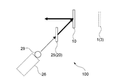
- the image display device 100 includes a plurality of virtual image screens 10, a multi-viewpoint video source 11, and a video control unit 12.
- the image to be displayed displayed by the multi-viewpoint video source 11 is displayed as a virtual image 1 by the virtual image screen 10.
- the image displayed on the multi-viewpoint video source 11 is controlled by the video control unit 12.
- the image includes a still image and a moving image (video).
- the direction of the surface on which the image display device 100 is arranged will be described as the horizontal direction, and the direction perpendicular to the horizontal direction will be described as the vertical direction.
- the plurality of virtual image screens 10 are arranged so as to cover at least a part around the central axis O.
- the central axis O is, for example, an axis that serves as a reference when displaying the virtual image 1.
- the central axis O is typically set parallel to the vertical direction.
- a plurality of virtual image screens 10 are arranged so as to partially surround the central axis O.
- the present technology can also be applied to a configuration in which a plurality of virtual image screens 10 are arranged so as to cover the entire circumference of the central axis O (see FIG. 10 and the like).
- the central axis O corresponds to a predetermined axis.
- the virtual image screen 10 displays the virtual image 1 of the image projected on each virtual image screen 10 with the central axis O as a reference.
- the virtual image screen 10 is transparent.
- a viewpoint image 4 which is a real image displayed by the multi-viewpoint image source 11 is projected on each virtual image screen 10.
- the virtual image 1 of the viewpoint image 4 is displayed with reference to the central axis O. Therefore, the virtual image screen 10 superimposes the virtual image 1 of the viewpoint image 4 displayed by the multi-viewpoint image source 11 on the background with the central axis O as a reference.
- a holographic optical element (HOE: Holographic Optical Element) is used as the virtual image screen 10.
- the HOE is an optical element using hologram technology, and realizes control of the traveling direction of light (optical path control) by diffracting light by interference fringes recorded in advance.
- a HOE configured to emit light incident at a predetermined incident angle at a predetermined emission angle is used as the virtual image screen 10.
- the light incident on the HOE (virtual image screen 10) can be emitted in a desired direction.
- the HOE may have the characteristics of a plane mirror and a curved mirror in order to control the position of the virtual image 1.
- a reflective holographic optical element (reflective HOE) is used as the virtual image screen 10.
- the reflective HOE is configured to diffract and reflect light incident in a specific angle range and transmit light in another angle range. For example, light incident on a reflective HOE in a specific angle range is emitted from a surface incident at an emission angle corresponding to the incident angle. Further, light incident at an incident angle other than a specific angle range passes through the reflective HOE with almost no diffraction due to interference fringes.
- the transparent virtual image screen 10 is configured, and the virtual image superimposed on the background can be displayed through the virtual image screen 10. In this way, the virtual image screen 10 functions as a combiner that superimposes and displays the virtual image 1 to be displayed on the background.
- the virtual image screen 10 is configured by using, for example, a volumetric HOE in which interference fringes are recorded inside the element. Further, a relief type (embossed type) HOE or the like in which interference fringes are recorded due to irregularities on the surface of the element or the like may be used as the virtual image screen 10. These HOEs are examples of diffractive optical elements (DOEs). As described above, the virtual image screen 10 is configured by using the diffractive optical element. In addition to the HOE that records interference fringes and diffracts light, a diffractive optical element of a type that diffracts light using a diffraction grating or the like having a predetermined pattern may be used.
- DOEs diffractive optical elements
- the specific configuration of the virtual image screen 10 is not limited.
- a half mirror may be used as the virtual image screen 10. Even when a half mirror is used, the virtual image 1 of the viewpoint image 4 can be superimposed and displayed on the background. The reflection by the half mirror is specular. Therefore, in the configuration in which the half mirror (virtual image screen 10) is vertically arranged as shown in FIG. 1, the viewing range of the virtual image 1 is a range in which the half mirror is viewed from diagonally above.
- any optical element capable of displaying a virtual image may be used as the virtual image screen 10.
- the virtual image screen 10 has a flat plate shape having a rectangular shape in a plan view, and has a front surface 13 and a back surface 14 which are opposite surfaces to each other.
- the virtual image screens 10 are arranged adjacent to each other at a predetermined angle with their back surfaces 14 facing the central axis O.
- Each virtual image screen 10 displays the virtual image 1 on the back surface 14 side facing the central axis O.
- each virtual image screen 10 is arranged parallel to the central axis O (vertical direction).
- the virtual image screens 10 may be arranged so as to be inclined with respect to the central axis O.
- three virtual image screens 10a to 10c are arranged adjacent to each other in this order from the left side.
- the plurality of virtual image screens 10 form a multi-faceted screen with the central axis O as a reference.
- the virtual image 1 of the viewpoint image 4 is displayed inside the multi-faceted screen (on the O side of the central axis).
- the multi-sided screen is a screen including a polygonal surface (for example, a polygonal surface constituting a regular polygonal prism) internally provided in a cylindrical surface centered on the central axis O.
- the multi-viewpoint video source 11 has a plurality of multi-viewpoint displays 20.
- the multi-viewpoint display 20 has a flat plate shape having a rectangular plan view, and has a display surface 21 for displaying the viewpoint image 4.
- the viewpoint image 4 displayed changes according to the viewing direction of the display surface 21.
- Each multi-view display 20 is arranged adjacent to each other at a predetermined angle with each display surface 21 facing the surface 13 of the corresponding virtual image screen 10.
- the multi-view display 20 constitutes the multi-sided display with the central axis O as a reference.
- the multi-viewpoint displays 20a to 20c are arranged toward the three virtual image screens 10a to 10c, respectively.
- a display unit for displaying the virtual image 1 is configured by a pair of the virtual image screen 10 and the multi-viewpoint display 20.
- FIG. 1A shows a side view of a display unit including a virtual image screen 10 and a multi-view display 20 as viewed from the side.
- An image display device is configured by rotating such a display unit around the central axis O and arranging a plurality of display units.
- the multi-view display 20 is arranged at a position shifted downward from the front of the virtual image screen 10. That is, the display surface 21 (multi-viewpoint display 20) is arranged so as not to block the virtual image displayed by the plurality of virtual image screens 10. This makes it possible to expand the display range of the virtual image 1, for example. Therefore, the image display device 100 has a configuration in which a multi-faceted display composed of a plurality of multi-viewpoint displays 20 is arranged outside the multi-faceted screen composed of the plurality of virtual image screens 10 while avoiding the optical path of the virtual image 1.
- the multi-viewpoint video source 11 corresponds to a display unit.
- the virtual image 1 displayed via the virtual image screen 10 is composed of an image (viewpoint image 4) displayed on the display surface 21 of the corresponding multi-viewpoint display 20. That is, it can be said that the user observing the virtual image 1 is looking at the display surface 21 through the virtual image screen 10.
- the direction in which the user sees the multi-viewpoint display 20 through the virtual image screen 10 will be referred to as a real image observation direction.
- the direction from the user's viewpoint 2 toward the central axis O is described as the virtual image observation direction.
- the viewpoint image 4 displayed in the real image observation direction corresponding to the viewpoint 2 is observed as the virtual image 1.
- FIG. 2 is a schematic view showing an example of the viewpoint image 4.
- the viewpoint image 4 is an image capable of displaying a state in which the display target 5 is viewed from different directions as a virtual image. Therefore, the viewpoint image 4 does not have to be an image of the display target 5 as it is viewed.
- the reflective virtual image screen 10 is used. That is, the virtual image screen 10 reflects the viewpoint image 4 projected from the display surface 21 to display the virtual image 1 of the viewpoint image 4. Therefore, the image displayed as the virtual image 1 is an image (mirror image inverted image) in which the left and right sides of the viewpoint image 4 displayed on the display surface 21 are inverted.
- the image control unit 12, which will be described later displays the viewpoint image 4 in which the image of the display target 5 viewed from the real image observation direction is mirror-inverted in the virtual image observation direction. As a result, it is possible to properly display the virtual image 1 of the display target 5 without inverting the left and right sides.
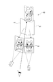
- FIG. 2A shows captured images 6a to 6c of a character (display target 5) holding a stick in his / her left hand, taken from the left side, the front side, and the right side.
- FIG. 2B shows viewpoint images 4a to 4c displaying the captured images 6a to 6c of FIG. 2A.
- the captured image 6 is an image obtained by capturing the character as it is.
- the viewpoint image 4 that reflects these and displays them as a virtual image is a mirror-inverted image in which the photographed image 6 is horizontally inverted. Therefore, the viewpoint images 4a to 4c are images in which the character to be displayed 5 holds the stick in his / her right hand.
- the viewpoint image 4 is generated based on, for example, an image of a stationary display target 5 taken by changing the shooting direction (shooting direction) without changing the shooting distance.
- the angle pitch for changing the shooting direction is typically set to a constant angle.
- the display target 5 may be an object existing in the real space, or a 3D model or the like generated by using computer graphics or the like.
- a deformed image or the like for correcting distortion or the like when displayed as a virtual image 1 may be used as the viewpoint image 4.
- a transmissive virtual image screen an image of the display target 5 as it is viewed is used as the viewpoint image 4.
- a plurality of viewpoint images 4 are switched and displayed on the display surface 21 of the multi-view display 20 according to the viewing direction. That is, the display surface 21 displays a plurality of viewpoint images 4 which are images of the display target 5 viewed from different directions.
- the direction in which each viewpoint image 4 is displayed from the display surface 21 (hereinafter, referred to as the display direction 7) is schematically illustrated by using black arrows.
- the display direction 7 is, for example, a direction in which light indicating the center of each viewpoint image 4 is emitted. Therefore, when the display surface 21 is directly viewed from the point where the display direction 7 is directed, an image composed of the image light emitted toward the display direction 7 is observed.
- the display surface 21 is configured to switch and display the viewpoint image 4 as shown in FIG. 2 for each of these display directions 7.
- a plurality of viewpoint images 4 displayed on each display surface 21 are projected onto each of the plurality of virtual image screens 10 by the plurality of display surfaces 21.
- a plurality of viewpoint images 4 are projected onto one virtual image screen 10 from one display surface 21 that is a pair in the display unit.
- the viewpoint image 4 is projected from a plurality of display surfaces 21 on one virtual image screen 10 or the viewpoint image 4 is projected from one display surface 21 on a plurality of virtual image screens 10. possible.
- a plurality of viewpoint images 4 are projected onto the virtual image screen 10.
- the virtual image screen 10 is displayed so that the virtual images 1 of the plurality of viewpoint images 4 are switched according to the viewing direction (position of the viewpoint 2) of the virtual image screen 10.
- the video control unit 12 controls the display of the viewpoint image 4 displayed on each multi-view display 20 (display surface 21) of the multi-view video source 11. Specifically, image data (video data) of the viewpoint image 4 displayed in each display direction is generated and displayed on each display surface 21.
- the video control unit 12 is configured by using a computer such as a PC or a server device. The operation of the video control unit 12 will be described later.
- the virtual image screen 10 and the multi-viewpoint display 20 are configured so that the virtual image plane 3 on which the virtual image 1 of each viewpoint image 4 is formed overlaps with each other about the central axis O. Will be done. This makes it possible to avoid a situation in which the position of the virtual image 1 of the display target 5 shifts depending on the viewing direction.
- the virtual image 1 does not necessarily have to overlap at the center.
- the multi-view display 20 is brought closer to the virtual image screen 10
- the virtual image surface 3 also approaches the virtual image screen 10.
- the viewpoint image 4 can be used for stereoscopic display. Therefore, the size of the display can be reduced by reducing the distance between the multi-view display 20 and the virtual image screen 10 within a range in which the virtual image 1 is connected.
- FIG. 3 is a schematic diagram for explaining a three-dimensional display by the image display device 100.
- a method of displaying the viewpoint image 4 for performing stereoscopic display will be described with reference to FIG.
- the virtual image 1 is observed through the two virtual image screens 10a and 10b by the user who points the viewpoint 2 toward the central axis O.
- the virtual image 1 observed by the user is a composite image of the virtual images 1a and 1b of the viewpoint images 4 displayed on the multi-viewpoint displays 20a and 20b.
- the user When the user attempts to view a display object through two virtual image screens 10a and 10b adjacent to each other, the user displays the display surfaces 21 of the two multi-viewpoint displays 20a and 20b reflected by the virtual image screens 10a and 10b, respectively. You will see it from a different angle. That is, the angle at which the user views each display surface 21 through the virtual image screen 10, that is, the direction in which the user looks at each display surface 21 is different from each other.
- the real image observation directions 8a and 8b directed to the multi-viewpoint displays 20a and 20b are schematically illustrated by white arrows.
- the virtual image observation direction 9 directed from the user's viewpoint 2 toward the central axis O is schematically illustrated by black arrows.
- the real image observation direction 8 corresponds to the first direction
- the virtual image observation direction 9 corresponds to the second direction.
- the image control unit 12 allows the central axis O from the user's viewpoint 2 with respect to the real image observation direction 8 in which the display surface 21 is viewed from the user's viewpoint 2 around the virtual image screen 10 through the virtual image screen 10.
- a viewpoint image 4 which is a virtual image of the display target 5 viewed from the virtual image observation direction 9 toward the display is displayed. That is, the viewpoint image 4 displayed from a certain viewpoint 2 toward the real image observation direction 8 in which the display surface 21 is expected is an image that displays the state of the display object 5 to be observed from the viewpoint 2 as a virtual image 1.
- the image control unit 12 displays a viewpoint image 4 that displays a display target 5 that can be seen from the user's viewpoint 2 (virtual image observation direction 9) with respect to the real image observation directions 8a and 8b that the user expects the display surfaces 21a and 21b. It is displayed on each display surface 21a and 21b.
- the viewpoint image 4 is displayed on each of the display surfaces 21a and 21b so that the central axes of the display target 5 displayed as the virtual image 1 are aligned with each other.
- the image of the display target 5 seen from the user's viewpoint 2 can be properly displayed as a virtual image.
- the viewpoint 2 (the viewpoint 2 () with respect to the real image observation direction 8 directed to the corresponding display surface 21.
- the viewpoint image 4 which is a virtual image of the display target 5 seen from the virtual image observation direction 9) is displayed.
- the display target 5 can be observed from multiple directions for each virtual image screen 10.
- the image display device 100 can display each viewpoint image of the display target 5 with an angular resolution corresponding to the angle pitch displayed by the multi-viewpoint image source 11 regardless of the position of the user's viewpoint 2. ..
- the image control unit 12 displays the viewpoint image 4 so that the virtual image of the display target 5 as viewed from the viewpoint 2 is switched at a predetermined angle pitch according to the movement of the viewpoint 2 of the user.
- the viewpoint image 4 that switches at a constant angle when the user moves, and it is possible to realize a natural stereoscopic display.
- the method of setting a predetermined angle pitch is not limited.
- the angle pitch is set so that the angle formed by a straight line horizontally connecting both ends of the virtual image screen 10 (multi-viewpoint display 20) from the central axis O (the central angle of the polygonal surface) is divided by an integer.
- the viewpoint image 4 can be smoothly switched even at the boundary of the adjacent virtual image screens 10.
- the angle pitch may be set according to the number of viewpoint images 4 that can be displayed on the multi-view display 20.
- the image display device 100 a plurality of viewpoint images 4 displayed on the display surface 21 of the multi-viewpoint image source 11 are projected onto the virtual image screen 10.
- the virtual image of the viewpoint image 4 can be switched and displayed for each virtual image screen 10.
- the image display device 100 is configured by arranging a plurality of display units including a virtual image screen 10 and a multi-viewpoint display 20 around the central axis O. By arranging in this way, when the virtual image screen 10 is viewed from multiple directions, the virtual image surface 3 on which the virtual image 1 is formed can be kept within a certain range, and the virtual image 1 can be observed without interruption. .. This makes it possible to significantly improve the motion parallax recognized as the user moves.
- the virtual image screen 10 (combiner) of HOE, it is possible to sufficiently improve the transparency and the brightness as compared with, for example, the Pepper's ghost type virtual image display using a half mirror.
- the virtual image screen 10 can be arranged upright in the vertical direction. Therefore, the horizontal width of the screen can be kept constant, and the virtual image 1 can be displayed in a wide display range. This makes it possible to display a large and bright virtual image 1 superimposed on the background through a highly transparent screen. This makes it possible to realize a stereoscopic display with a high sense of reality.
- FIG. 4 is a schematic diagram showing a specific configuration example of the image display device 100.
- 5 and 6 are a side view and a top view of the image display device 100 shown in FIG.
- a multi-projector type display is used as the multi-viewpoint display 20 of the multi-viewpoint video source 11.
- the multi-viewpoint video source 11 has a plurality of real image screens 25 and a plurality of projectors 26.
- a plurality of projectors 26 are provided for each real image screen 25 to form a projector array.
- the real image screen 25 and the projector array function as the multi-view display 20 described above.
- the real image screen 25 is a transmissive anisotropic diffusion screen, and has a projection surface 27 on which an image is projected from each projector 26 and an image display surface 28 on the opposite side of the projection surface.
- the image display surface 28 becomes the display surface 21 described above.
- the plurality of real image screens 25 are arranged on the corresponding virtual image screens 10 so as to face the image display surface 28 (display surface 21).
- the real image screen 25 has anisotropic diffusion characteristics in which the diffusivity differs between the horizontal direction and the vertical direction. For example, the degree of diffusion in the horizontal direction is set to be smaller than that in the vertical direction, and is configured to have a narrow diffusion characteristic with respect to the horizontal direction.
- the angle range of the light diffused in the horizontal direction can be narrowed, and the plurality of viewpoint images 4 can be emitted in a desired direction.
- the viewpoint image 4 can be projected in the vertical direction without widening the angle of incidence on the virtual image screen 10.
- the real image screen 25 a reflective type and arrange the projectors 26 inside the device (see FIG. 10 and the like).
- the real image screen 25 is composed of a lens diffuser or the like whose diffusion degree is biased in the horizontal and vertical directions by, for example, a microlens array or the like. Further, a transmission type HOE in which the anisotropic diffusion characteristics are recorded may be used as the real image screen 25.
- HOE transmission type HOE in which the anisotropic diffusion characteristics are recorded
- the projection angle of the projector 26 with respect to the real image screen 25 can be reduced while maintaining the incident angle with respect to the virtual image screen 10. This makes it possible to reduce the size of the entire multi-viewpoint video source 11. Further, since it is easy to control the diffusion characteristics in HOE, it is possible to display the viewpoint image 4 having better image quality.
- the plurality of projectors 26 project images constituting the viewpoint image 4 on the projection surface 27 of the real image screen 25.
- the plurality of projectors 26 project images onto the real image screen 25 from different directions.
- each projector is arranged so that the light emitting point 29 of the projector 26 is on the circumference with respect to the center of the real image screen 25.
- a projector module in which a plurality of light emitting points 29 are integrated so as to be arranged in a circumferential shape may be used.
- each projector 26 projects an image from diagonally below the real image screen 25. This projection angle is set according to, for example, the projection angle of the display surface 21 with respect to the virtual image screen 10.
- An image is projected on the projection surface 27 of the real image screen 25 by these projectors 26, and the viewpoint image 4 is displayed on the display surface 21.
- the pixel light constituting each pixel of the image displayed on the real image screen 25 is emitted according to the direction of incident on the projection surface 27.
- a part of the images (typically strip-shaped images) projected by each of the plurality of projectors 26 can be combined to display a plurality of viewpoint images 4 in each display direction. It will be possible.
- FIG. 4 schematically shows a plurality of viewpoint images 4 viewed from the projection surface 27 side.
- the angle pitch at which the plurality of projectors 26 project an image on the real image screen 25 is the angle pitch (viewpoint pitch) of the viewpoint image 4 that can be displayed by the multi-viewpoint image source 11.
- this angle pitch smaller than the parallax angle of both eyes, it is possible to display different viewpoint images 4 for both eyes of the user to give binocular parallax, and it is possible to reproduce the stereoscopic effect of the display target. It becomes.
- Even when the angle pitch is rough it is possible to give motion parallax to the display target 5 and make it appear three-dimensional by switching and displaying the viewpoint image 4 according to the movement of the viewpoint position of the user. ..
- the diffusion angle of the real image screen 25 in the horizontal direction is equal to the angular pitch of the projector 26. This makes it possible to avoid crosstalk or the like in which the viewpoint images 4 to be displayed in different directions are observed at the same time.
- the range of the entire projection angle at which the plurality of projectors 26 project an image on the real image screen 25 is the viewing range (viewable angle) of the viewpoint image that can be displayed on the real image screen 25. Therefore, for example, in order to display the display target 5 without being cut off, it is desirable to project the image at an angle as large as possible. For example, it is possible to widen the overall projection angle by increasing the projection angle of view of each projector 26.
- the viewpoint image 4 can be displayed using colored light having a narrow wavelength width, and the diffraction efficiency in the HOE (virtual image screen 10 or real image screen 25) can be improved and the display brightness can be increased.
- an LED light source may be used as the light source of the projector 26.
- the specific configuration of the projector 26 is not limited.
- FIG. 7 is a schematic diagram for explaining a method of displaying a viewpoint image projected on the reflective virtual image screen 10.
- the user is observing the virtual image along the virtual image observation direction 9 passing through the boundary between the virtual image screens 10a and 10b adjacent to each other.
- the direction from the central axis O toward the boundary is set as the starting point direction which is the starting point when the display target 5 is displayed.
- the starting point direction is, for example, the direction in which the front surface of the display target 5 is directed.
- the direction of clockwise rotation with respect to the central axis O is defined as the positive direction of the azimuth angle.
- the starting point direction of the display target 5 (for example, the direction of observing the front of the display target 5 (virtual image)) is represented by an azimuth angle with respect to the central axis O.
- the azimuth in the starting point direction is ⁇ 0 degrees. Therefore, in FIG. 7, the virtual image 1 is observed from the viewpoint 2 in which the virtual image observation direction 9 has an azimuth angle ⁇ 0.
- the angle at which the center of the real image screen 25a on the left side when viewed from the user's viewpoint 2 is seen is ⁇ i1 .
- the angle at which the center of the real image screen 25b on the right side when viewed from the user's viewpoint 2 is seen is ⁇ i2 .
- ⁇ i1 and ⁇ i2 will be described as angles in the horizontal plane.
- ⁇ i1 ( ⁇ i2 ) a straight line that projects an optical path toward the center of the real image screen 25a (real image screen 25b) via the virtual image screen 10a (real image screen 10b) onto a horizontal plane is the real image screen 25a (real image screen 25b). It is the angle formed with the normal line of.
- These angles can be said to represent the directions in which the real image screens 25a and 25b are expected (real image observation directions 8a and 8b).
- the angle ⁇ i1 in which the real image screen 25a is expected is ( ⁇ i1- ⁇ ( ⁇ ) ⁇ ⁇ ).
- ⁇ ( ⁇ ) is a positive coefficient.
- ⁇ i1 decreases as the viewpoint 2 moves by ⁇ . This means that the direction in which the real image screen 25a seen from the upper surface is seen rotates counterclockwise.
- the angle ⁇ i2 in which the real image screen 25b is expected is ( ⁇ i2 + ⁇ ( ⁇ ) ⁇ ⁇ ).
- ⁇ ( ⁇ ) is a positive coefficient.
- ⁇ i1 increases as the viewpoint 2 moves by ⁇ . This means that the direction in which the real image screen 25b seen from the upper surface is seen rotates counterclockwise.
- the viewpoint image 4 of the display target 5 of ⁇ 0 + ⁇ degree is displayed on each display surface 21 so that the user can see from there. It is possible to show a virtual image of the display target 5.
- ⁇ ( ⁇ ) is a coefficient related to the amount of change in the angle ⁇ i1 that looks into the real image screen 25a on the left side when viewed from the viewpoint 2, and ⁇ ( ⁇ ) looks into the real image screen 25b on the right side when viewed from the viewpoint 2. It is a coefficient related to the amount of change in the angle ⁇ i2. These coefficients are parameters for correcting the effects of projection angle conversion, lens effect, HOE diffraction aberration, etc. (angle deviation, etc.), and are expressed as a function of the azimuth angle ⁇ of the viewpoint 2 with respect to the azimuth angle ⁇ 0. Will be done. By correcting the amount of change using such a coefficient, it is possible to correctly display the virtual image 1 of the display target 5.
- FIG. 8 is a schematic view showing an example of a viewpoint image displayed according to the observation direction.
- a viewpoint image displayed according to the observation direction.
- an image of a character (display target 5) holding a stick in the left hand as viewed from the front is displayed.
- a character holding a stick in the right hand is displayed as the viewpoint images 4a and 4b in the real image observation directions 8a and 8b.
- FIG. 8 shows viewpoint images 4a and 4b observed when the real image screens 25a and 25b are viewed from the front side along the real image observation directions 8a and 8b.
- the characters rotated counterclockwise are reflected on the real image screens 25a and 25b.
- the viewpoint images 4a and 4b are displayed.
- the viewpoint images 4a and 4b showing the character rotated clockwise are displayed on the real image screens 25a and 25b.
- the display target 5 rotated in the direction opposite to the movement of the user is displayed on the display surface 21 of the real image screen 25. To. As a result, the display target 5 can be properly displayed according to the movement of the user.
- a plurality of transparent virtual image screens 10 are arranged so as to cover at least a part around the central axis O. Further, a plurality of display surfaces 21 for displaying the plurality of viewpoint images 4 of the display target 5 in different directions are provided. A plurality of viewpoint images 4 are projected on each virtual image screen 10. At this time, in the direction in which the display surface 21 is viewed from a certain viewpoint 2 via the virtual image screen 10 (real image observation direction 8), the viewpoint becomes the virtual image 1 of the display target 5 that can be seen when the central axis O is viewed from the viewpoint 2. Image 4 is displayed. This makes it possible to realize a stereoscopic display with a high sense of reality.
- Pepper's ghost As a method of displaying an object using a virtual image, a method called Pepper's ghost is known in which a half mirror is tilted with respect to the horizontal to display a virtual image of the object.
- a viewpoint image in which the viewing direction of the object changes according to the movement of the user, and the object.
- the sense of reality may be impaired.
- Another possible method is to make the half mirror multi-faceted to display the object in three dimensions. In this case, when crossing adjacent surfaces, the images are switched violently, which may impair the sense of reality.
- the size of the reflecting surface may be reduced and the image size may be reduced by increasing the number of surfaces.
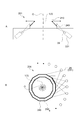
- FIG. 9 is a schematic view of the virtual image display device 90 shown as a comparative example.
- a virtual image display device 90 that displays a virtual image 1 using the HOE 91 is schematically shown.
- an image of the target 92 viewed from one direction is projected onto the HOE 91 arranged in a polygonal columnar shape. Therefore, when the user's line of sight crosses the boundary of the HOE 91, the image of the target 92 changes abruptly, which may impair the realism of the stereoscopic display.
- the viewpoint image of the display target 5 is projected on each of the plurality of virtual image screens 10.
- a viewpoint image of the display target 5 viewed from multiple directions is displayed for each virtual image screen 10.
- the plurality of virtual image screens 10 are arranged so as to surround the central axis.
- the viewpoint image 4 is displayed so that the display target seen from the viewpoint 2 is displayed in the direction in which the user's viewpoint 2 sees the display surface 21 through the virtual image screen 10 (virtual image observation direction 9). That is, the display of the display surface 21 is controlled so that the viewpoint image 4 of the display target viewed from that direction is formed according to the difference in the observation direction of each virtual image surface 3 viewed from the user. This makes it possible to properly display the virtual image 1 of the display object 5 to be observed from that viewpoint regardless of the position of the viewpoint 2.
- HOE is used as the virtual image screen 10. This makes it possible to arrange the virtual image screen 10 upright in the vertical direction. As a result, it is possible to improve the reproducibility of the viewpoint image 4 of the display target 5 including the case of crossing the boundary of the virtual image screen 10 without reducing the image size, and it is possible to realize a stereoscopic display with a sense of reality. It will be possible.
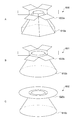
- FIG. 10 is a schematic diagram showing a configuration example of the image display device according to the second embodiment.
- 10A is a perspective view of the image display device 200
- FIG. 10B is a schematic view showing an example of the internal configuration of the image display device 200.
- 11 and 12 are a cross-sectional view and a top view of the image display device 200 shown in FIG.
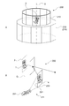
- the image display device 200 has a plurality of virtual image screens 210 and a multi-viewpoint image source 211, and functions as an omnidirectional display capable of displaying a virtual image 1 when the display target 5 is viewed from all directions.
- the plurality of virtual image screens 210 are arranged so as to cover the entire circumference of the central axis O. These virtual image screens 210 form a polygonal multi-faceted screen with reference to the central axis O.
- the virtual image screen 210 is a reflective holographic optical element (HOE). Therefore, in the image display device 200, the virtual image 1 of the viewpoint image 4 of the display target 5 projected from the outside of the multi-faceted screen is displayed inside the multi-faceted screen.
- the HOE may have the characteristics of a plane mirror and a curved mirror in order to control the position of the virtual image 1.
- the multi-viewpoint video source 211 has a plurality of real image screens 230 and a plurality of projectors 231 that project images onto the real image screens 230 from different directions.
- the real image screen 230 and the plurality of projectors 231 constitute a multi-viewpoint display.
- the real image screen 230 is a reflective anisotropic diffusion screen. Therefore, in the real image screen 230, the surface on which the image is projected from each projector 231 is the display surface 221 (image display surface) on which the viewpoint image 4 is displayed.
- the plurality of real image screens 230 are arranged so that the display surface 221 faces the corresponding virtual image screen 210.
- These real image screens 230 constitute a polygonal columnar multi-sided display with reference to the central axis O.
- the real image screen 230 has anisotropic diffusing characteristics in which the diffusivity differs in the horizontal direction and the vertical direction, and is configured by, for example, attaching a reflecting plate to a transmissive lens diffusing plate. Further, a reflective HOE in which the anisotropic diffusion characteristics are recorded may be used as the real image screen 230. By using HOE, it is possible to reduce the size of the entire multi-viewpoint video source 211 and display the viewpoint image 4 with good image quality.
- the plurality of projectors 231 project images from the inside of the plurality of real image screens 230 (multi-faceted displays) arranged around the central axis O toward each display surface 221.
- a laser light source or an LED light source is used as the light source of the projector 231.
- the wavelength width of the colored light may be limited by using a wavelength filter or the like.
- FIG. 10B schematically shows a display unit including a reflective virtual image screen 210 and a reflective real image screen 230 as an example of the internal configuration of the image display device 200.
- a projector array composed of a plurality of projectors 231 is provided inside the real image screen 230.
- FIG. 10B it is possible to use a configuration in which an image is directly projected from each projector 231 onto the real image screen 230. is there.
- FIG. 11 schematically shows a cross-sectional view of the image display device 200 cut along a cross section including the central axis O.
- FIG. 12 schematically shows a top view corresponding to the configuration shown in FIG. In FIGS. 11 and 12, the image is projected onto the real image screen 230 in a manner different from that in FIG. 10B.
- the projector 231 is arranged outward and upward along the outer circumference of the device.
- the light of the image projected from the projector 231 is reflected through a mirror (not shown) and is incident on the real image screen 230 arranged on the side opposite to the side on which the projector 231 is arranged. That is, an image is projected onto each real image screen 230 from a light emitting point 29 (mirror) on the opposite side of the central axis O. This makes it possible to increase the projection distance and increase the size of the projected image.
- each projector 231 is arranged so that its light emitting points 29 are lined up along the circumference which is the outer circumference of the device.
- the integrated projector module may be configured so that a plurality of light emitting points are arranged along the outer circumference.
- the angle pitch at which the plurality of projectors 231 project an image onto the real image screen 230 is the angle pitch (viewpoint pitch) of the viewpoint image 4 that can be displayed by the multi-viewpoint image source 211.
- the angle pitch sufficiently small, it is possible to perform stereoscopic display that gives binocular parallax.
- the range of the entire projection angle at which the plurality of projectors 231 project the image on the real image screen 230 is the viewing range (viewable angle) of the viewpoint image that can be displayed on the real image screen 230. Therefore, by increasing the projection angle of view of each projector 231, it is possible to display the display target 5 without being cut off.
- a configuration in which the light emitted from one projector 231 is divided and projected may be used. By split projection, it is possible to create a plurality of light emitting points 29 from one projector 231.
- FIG. 13 is a schematic diagram showing an example of divided projection.
- three division mirrors 235a to 235c that divide the image projected by the projector 231 are used.
- the image projected from the projector 231 is divided by the divided mirrors 235a to 235c, and is divided into three directions and projected as a divided image while being enlarged.
- each of the divided mirrors 235a to 235c can be regarded as a light emitting point for projecting the divided image.
- the number of split mirrors 235 is not limited. By using the split mirror 235, the number of projectors 231 can be reduced, and the cost of the apparatus can be suppressed.
- FIG. 14 is a schematic view showing an example of the display position of the virtual image 1 in the image display device 200.
- 14A to 14C schematically show an example of the display position of the virtual image 1 of the viewpoint image 4 displayed by the multi-viewpoint image source 211.
- the virtual images 1 of the plurality of viewpoint images 4 are displayed so that the center lines of the virtual image planes 3 overlap each other.
- the center line of the virtual image plane 3 is a center line parallel to the vertical direction (center axis O).
- the centerline of each virtual image plane 3 is displayed so as to coincide with the central axis O.
- the virtual images 1 of the plurality of viewpoint images 4 are displayed so that a part of the virtual image surfaces 3 overlap each other.
- the virtual image 1 does not necessarily have to be centered, and may be partially overlapped.
- the multi-viewpoint image source 211 real image screen 230
- the device can be miniaturized.
- the image display device 200 can display the virtual image 1 so that the image of the display target 5 is observed before and after the virtual image surface 3. Therefore, even when the virtual image planes 3 do not overlap with each other on the central axis O, the virtual image can be displayed with the central axis O as a reference by displaying the virtual image 1 on the back side.
- the virtual images 1 of the plurality of viewpoint images 4 are displayed so that the virtual image surfaces 3 are in contact with each other.
- the distance between the real image screen 230 and the virtual image screen 210 can be sufficiently shortened, and for example, a substantially tubular image display device having a small step on the side surface can be realized.
- FIG. 15 is a schematic view showing another configuration example of the image display device.
- a transmissive real image screen 240 is used instead of the reflective real image screen.
- 15A and 15B are a cross-sectional view and a top view of an image display device 201 equipped with a transmissive real image screen 240.
- the projector 231 is arranged outside the real image screen 240, and an image is directly projected from each projector 231.
- FIG. 15B by providing the projector 231 outside the real image screen 240, the degree of freedom in arranging the projector 231 is improved, and it is easy to project an image from one projector 231 to a plurality of real image screens 240. It is possible to realize.
- FIG. 16 is a schematic view showing a configuration example of the image display device according to the third embodiment.
- 16A is a perspective view of the image display device 300
- FIG. 16B is a schematic view showing an example of the internal configuration of the image display device 300.
- 17 and 18 are side views and top views of the image display device 300 shown in FIG.
- an omnidirectional display is configured by using a direct-view stereoscopic display 340.
- the image display device 300 has a plurality of virtual image screens 310 and a multi-viewpoint image source 311 composed of a plurality of stereoscopic display 340s.
- Each virtual image screen 310 is configured in the same manner as the virtual image screen 210 of the image display device 200 described with reference to, for example, FIG. That is, the virtual image screen 310 is a reflective HOE and is arranged so as to cover the entire circumference of the central axis O.
- the stereoscopic display 340 is a direct-view type display capable of displaying a stereoscopic image without using dedicated glasses or the like.
- the stereoscopic display 340 has an image display surface 341 for displaying a stereoscopic image.
- a direct-view stereoscopic display generally displays a stereoscopic image by displaying a plurality of viewpoint images 4 in a plurality of display directions. Therefore, in the present embodiment, the image display surface 341 of the direct-view stereoscopic display 340 is the display surface for displaying the viewpoint image 4.
- Each stereoscopic display 340 is arranged with the image display surface 341 facing the corresponding virtual image screen 310. As shown in FIGS. 16 to 18, it can be said that the image display device 300 has a configuration in which the real image screen 230 of the image display device 200 shown in FIG. 10 or the like is replaced with a stereoscopic display 340.
- the stereoscopic display 340 displays a plurality of viewpoint images 4 by any one of a lenticular lens method, a lens array method, and a parallax barrier method.
- the lenticular lens method is a method of displaying images in different directions by using a lenticular lens that disperses light in the horizontal direction. By using the lenticular lens method, it is possible to display a brighter viewpoint image 4 as compared with the parallax barrier method or the like.
- the lens array method is a method of displaying the viewpoint image 4 by dispersing light in the vertical and horizontal directions using a microlens array. By using the lens array method, it is possible to increase the number of viewpoints in the vertical direction, and it is possible to express with a high sense of reality.
- the parallax barrier method is a method of displaying the viewpoint image 4 by using a parallax barrier or the like that selectively blocks the light of each pixel, and can realize a wider viewing angle as compared with other methods.
- the original image of the viewpoint image 4 is displayed by a flat panel display such as an LCD (Liquid Crystal Display).
- the light source used for the backlight of the display is preferably a laser light source.
- the wavelength width is narrowed by using a wavelength filter or the like to reduce image blurring and color shift due to color dispersion on the virtual image screen 310 (HOE).
- HOE virtual image screen 310
- any method capable of three-dimensional display with the naked eye may be used.
- the stereoscopic display 340 does not necessarily have to display the viewpoint image 4 at an angle pitch capable of stereoscopic viewing.
- a multi-viewpoint display may be used that displays a viewpoint image at a level at which binocular parallax does not occur.
- the image display device 300 includes a polygonal prism type multi-sided screen (virtual image screen 310) and a polygonal pillar-shaped multi-sided display (stereoscopic display device) arranged around the polygonal pillar type multi-sided screen (virtual image screen 310).
- a polygonal prism type multi-sided screen virtual image screen 310
- a polygonal pillar-shaped multi-sided display stereoscopic display device arranged around the polygonal pillar type multi-sided screen (virtual image screen 310).
- the image display device 300 includes a polygonal prism type multi-sided screen (virtual image screen 310) and a polygonal pillar-shaped multi-sided display (stereoscopic display device) arranged around the polygonal pillar type multi-sided screen (virtual image screen 310).
- FIG. 19 is a schematic view showing a configuration example of the image display device according to the fourth embodiment.
- the left and right views of FIG. 19 are a cross-sectional view and a top view of the image display device 400.
- a transmission type holographic optical element transmission type HOE
- transmission type HOE transmission type HOE
- the transmissive HOE is configured to diffract and transmit light incident in a specific angle range and transmit light in other angle ranges. For example, light incident on a transmissive HOE in a specific angle range is transmitted through the HOE main body and emitted from a surface opposite to the surface on which the light is incident at an emission angle corresponding to the incident angle. Further, light incident at an incident angle other than a specific angle range passes through the transmissive HOE with almost no diffraction due to interference fringes.
- the plurality of virtual image screens 410 are arranged so as to cover the entire circumference of the central axis O, and form a polygonal columnar multifaceted screen.
- the viewpoint image 4 is projected onto the back surface 414 of the virtual image screen 410 from diagonally below.
- the light constituting the viewpoint image 4 projected on the back surface 414 is emitted along the horizontal direction toward the front surface 413 of the virtual image screen 410.
- the user observing the virtual image screen 410 observes the virtual image 1 of the viewpoint image 4 on an extension line extending the optical path of the light emitted toward the front surface 413 toward the back surface 414.
- the image display device 400 and the virtual image planes 3 forming the virtual image 1 of each viewpoint image 4 are configured to intersect at the central axis O.
- the virtual image screen 410 is a transmissive mirror (transmissive mirror HOE) that transmits an image and displays it as a virtual image.
- a virtual image screen 410 configured as a transmissive planar mirror is used. It is also possible to configure the virtual image screen 410 as a transmissive curved mirror in which the HOE has a lens function (see FIG. 22).
- the virtual image screen 410 is configured using a single transmissive HOE.
- the virtual image screen 410 may be formed by joining two reflective HOEs. In this case, transmission can be realized by diffraction reflection twice.
- the virtual image screen 410 a transmissive type, for example, the multi-viewpoint image source 411 can be inserted inside the device more than the virtual image screen 410, and the device can be miniaturized.
- the virtual image screen 410 may be arranged so as to cover a part of the periphery of the central axis O.
- the multi-viewpoint video source 411 has a plurality of multi-viewpoint displays 420.
- the multi-view display 420 is arranged so as to cover the entire circumference of the central axis O, and constitutes a polygonal columnar multi-sided display.
- the virtual image screen 410 is a transmissive type. Therefore, the multi-viewpoint display 420 needs to project the viewpoint image 4 from diagonally below with respect to the back surface 414 of the virtual image screen 410, for example. Therefore, in the image display device 400, the multi-view display 420 is arranged at a position closer to the central axis O than the virtual image screen 410.
- the multi-viewpoint display 420 it is possible to use the multi-projector type real image screen described in the above embodiment or the direct-view type stereoscopic display.
- the transmissive virtual image screen 410 when used, the distance between the multi-view display 420, which is the image source, and the virtual image screen 410 becomes close, so that the virtual image 1 is the central axis O. It can be difficult to display them so that they overlap with each other. Even in such a case, it is possible to display the display target 5 from multiple viewpoints by displaying the virtual images 1 viewed from each direction so as to be connected.
- FIG. 20 is a schematic diagram for explaining a display method of the viewpoint image 4 projected on the transmissive virtual image screen 410.
- the direction in which the user looks at the multi-view display 420 through the virtual image screen 410 real image observation direction 8
- the direction from the user's viewpoint 2 toward the central axis are shown by using white and black arrows. It is schematically illustrated.
- FIG. 20 it is assumed that the user is observing the virtual image along the virtual image observation direction 9 passing through the boundary between the virtual image screens 410a and 410b adjacent to each other.
- the direction from the central axis O toward the boundary is set as the starting point direction which is the starting point when the display target 5 is displayed.
- a transmissive virtual image screen 410 is used. That is, the virtual image screen 410 transmits the viewpoint image 4 projected from the display surface 421 and displays the virtual image 1 of the viewpoint image 4. Therefore, the viewpoint image 4 displayed on the display surface 421 becomes an image displayed as a virtual image 1 as it is.
- the image control unit (not shown) displays the viewpoint image 4 of the display target 5 viewed from the real image observation direction 8 in the virtual image observation direction 9. As a result, the virtual image 1 of the display target 5 can be properly displayed.
- the starting point direction of the display target 5 (for example, the direction of observing the front of the display target 5 (virtual image)) is represented by an azimuth angle with respect to the central axis O.
- the azimuth in the starting point direction is ⁇ 0 degrees. Therefore, in FIG. 20, the virtual image 1 is observed from the viewpoint 2 in which the virtual image observation direction 9 has an azimuth angle ⁇ 0.
- the angle at which the center of the multi-viewpoint display 420a on the left side when viewed from the user's viewpoint 2 is seen is ⁇ i1 .
- the angle at which the center of the multi-view display 420b on the right side when viewed from the user's viewpoint 2 is seen is ⁇ i2 .
- ⁇ i1 and ⁇ i2 will be described as angles in the horizontal plane.
- ⁇ i1 ( ⁇ i2 ) a straight line that projects an optical path toward the center of the multi-view display 420a (multi-view display 420b) via the virtual image screen 410a (virtual image screen 410b) onto a horizontal plane is a multi-view display 420a (multi-view display 420a). It is an angle formed with the normal of the viewpoint display 420b).
- These angles can be said to represent the directions in which the multi-viewpoint displays 420a and 420b are expected (real image observation directions 8a and 8b).
- the user's viewpoint 2 moves by ⁇ and the azimuth angle of the virtual image observation direction 9 becomes ( ⁇ 0 + ⁇ ). That is, it is assumed that the viewpoint 2 is rotated clockwise with respect to the central axis O by ⁇ .
- the angle ⁇ i1 that looks into the multi-view display 420a is ( ⁇ i1- ⁇ '( ⁇ ) ⁇ ⁇ ).
- ⁇ '( ⁇ ) is a positive coefficient.
- ⁇ i1 decreases as the viewpoint 2 moves by ⁇ . This means that the direction in which the multi-viewpoint display 420a viewed from above is viewed rotates clockwise.
- the angle ⁇ i2 in which the multi-view display 420b is expected is ( ⁇ i2 + ⁇ '( ⁇ ) ⁇ ⁇ ).
- ⁇ '( ⁇ ) is a positive coefficient.
- ⁇ i2 increases as the viewpoint 2 moves by ⁇ . This means that the direction in which the multi-view display 420b viewed from above is viewed rotates clockwise.
- the viewpoint image 4 of the display target 5 of ⁇ 0 + ⁇ degree is displayed on each display surface 421 so that the user can see from there. It is possible to show a virtual image of the display target 5. Further, when the transmissive virtual image screen 410 is used, the direction in which the viewing direction rotates is opposite to that when the reflective virtual image screen 410 described with reference to FIG. 7 is used.
- ⁇ '( ⁇ ) and ⁇ '( ⁇ ) are coefficients related to the amount of change in the angles ( ⁇ i1 and ⁇ i2 ) for each multi-viewpoint display, such as projection angle conversion, lens effect, and HOE diffraction aberration. It is a parameter that corrects the influence of (angle deviation, etc.). In particular, when the lens function described below is provided, it is conceivable that the traveling direction of light changes significantly and aberration also occurs. By setting a coefficient and correcting the amount of change so as to reduce these effects, it is possible to correctly display the virtual image 1 of the display target 5.
- FIG. 21 is a schematic view showing an example of a virtual image displayed by a transmissive virtual image screen 410 having a lens function.
- the virtual image 1 is observed through the virtual image screen 410.
- the display position of the virtual image 1 and the size of the virtual image 1 are changed.
- the viewpoint 2 directed to the center of the lens there is no change in the direction of the optical path for displaying the virtual image.
- the direction in which the virtual image 1 is viewed changes due to the addition of the lens function.
- the direction in which the multi-viewpoint display 420 is viewed does not change even if the lens function is added.
- the optical path of the light displaying the virtual image 1 may change, and various aberrations may occur.
- the viewpoint image 4 is appropriately corrected so as to suppress such a change in angle and deformation due to aberration.
- FIG. 22 is a schematic view showing another configuration example of the image display device.
- the image display device 401 shown in FIG. 22A shows a configuration in which the virtual image screen 410 is provided with a lens function in the image display device 400 shown in FIG.
- this configuration by setting the display position of the virtual image 1 to a position far from the virtual image screen 410, it is possible to display the virtual image 1 so as to overlap with the central axis O. In this way, it is possible to appropriately adjust the display position of the virtual image 1 by using the lens function.
- the multi-sided screen composed of the virtual image screen 410 and the multi-sided display composed of the multi-viewpoint display 420 are configured to be internally installed in the same cylinder. Further, the viewpoint image 4 is projected on the virtual image screen 410 from the multi-viewpoint display 420 arranged on the opposite side of the central axis O. By projecting the image from the opposite side in this way, it is possible to increase the projection distance. Further, it is possible to realize a tubular image display device 400 having no step.
- FIG. 23 is a schematic view showing a configuration example of the image display device according to the fifth embodiment.
- the image display device 500 according to the present embodiment is configured by using a curved image screen 510.
- the image display device 500 has a cylindrical virtual image screen 510 and a cylindrical real image screen 525 having a radius larger than that of the virtual image screen 510.
- the virtual image screen 510 and the real image screen 525 are arranged about the central axis O, respectively.
- the real image screen 525 is arranged below the virtual image screen 510 so as not to block the display of the virtual image 1.
- the virtual image screen 510 and the real image screen 525 are composed of, for example, a reflective HOE.
- the image display device 500 has a plurality of projectors 526 that project images on the real image screen 525.
- FIG. 23 shows each light emitting point 29 of the plurality of projectors 526. It can be said that the image display device 500 has a cylindrical configuration in which the multi-sided screen (virtual image screen) and the multi-sided display (real image screen) of the image display device 200 described with reference to FIGS. 10 to 12 are formed into a cylinder.
- the plurality of projectors 526 are arranged so that the light emitting points 29 are arranged on the circumference along the real image screen 525. From each light emitting point 29, an image is projected toward the real image screen 525 on the opposite side of the central axis O. As a result, images are projected from the plurality of projectors 526 from different directions on the display surface 521 inside the real image screen 525, and the viewpoint image 4 can be displayed.
- the viewpoint image 4 displayed on the display surface 521 is projected on the virtual image screen 510.
- a cylindrical virtual image surface 3 centered on the central axis O is formed inside the virtual image screen 510.
- the virtual image of the display target 5 is displayed on the virtual image surface 3.
- the virtual image screen 510 When the virtual image screen 510 is made into a cylindrical shape, the virtual image surfaces 3 are in a connected state as shown in FIG. 23. Therefore, in the image display device 500, the seam of the virtual image screen 510 is eliminated. Therefore, the virtual image of the display target 5 can be displayed smoothly, and there is an effect of sufficiently improving the sense of reality. Further, the maximum value of the angle at which the virtual image screen 510 is seen is smaller than that when the polygonal columnar virtual image screen 510 is used.
- the angle at which the virtual image screen 510 is seen is, for example, an angle formed by the normal direction and the line-of-sight direction of the surface at the intersection of the line-of-sight directions with respect to the surface of the virtual image screen 510.
- the angle at which the virtual image screen 510 is seen changes continuously as the viewpoint 2 moves. Therefore, when the viewpoint 2 is moved, the decrease or fluctuation of the brightness, which tends to occur due to the switching of the surfaces, does not occur. As a result, it is possible to avoid a situation in which the brightness of the virtual image changes unnaturally and realize a natural stereoscopic display. These are the same even when the transmissive HOE is used as the virtual image screen 510.
- the real image screen 525 also has a cylindrical shape
- the present invention is not limited to this.
- the real image screen 525 may have a polygonal prism shape.
- the real image screen 525 may have a cylindrical shape and the virtual image screen 510 may have a polygonal prism shape.
- at least one of the virtual image screen 510 and the real image screen 525 (display surface) has a curved surface shape.
- FIG. 24 is a schematic diagram showing another configuration example of the image display device.
- the image display device 501 shown in FIG. 24 includes an arc-shaped virtual image screen 510 and a real image screen 525, and a plurality of projectors 526 that project images toward the real image screen 525.
- the image display device 500 shown in FIG. 23 is partially cut out.
- the curved virtual image screen 510 (real image screen 525) may be arranged so as to cover a part of the periphery of the central axis O.
- the specific configuration of the curved screen is not limited.
- a virtual image screen 510 may be used in which the cross section in the horizontal direction is an arbitrary curve such as an ellipse, a bipolar line, or a quadratic curve.
- FIG. 25 is a schematic view showing a configuration example of the image display device according to the sixth embodiment.
- a half mirror is used as the virtual image screen 610.
- the light incident on the half mirror is specularly reflected at an emission angle equal to the incident angle. Therefore, for example, when light is emitted in the horizontal direction (a virtual image is displayed), the light is incident on a mirror surface inclined by 45 degrees from the vertical direction.
- a plurality of virtual image screens 610a form a polygonal pyramid-shaped multifaceted screen arranged with the apex side facing upward. Further, above the multi-faceted screen, a plurality of multi-viewpoint displays 620a for displaying the viewpoint image 4 toward each side are arranged.
- a conical virtual image screen 610b arranged with the apex side facing upward is used.
- a plurality of multi-viewpoint displays 620b are arranged above the virtual image screen 610a as in FIG. 25A. This makes it possible to display the virtual image of the display target 5 toward the outer periphery of the virtual image screens 610a and 610b.
- a multi-viewpoint display 620c capable of displaying the viewpoint image 4 in an annular shape is arranged above the conical virtual image screen 610c arranged with the apex side facing upward.
- the annular multi-viewpoint display 620c it is possible to continuously display the virtual image 1 over the entire circumference.
- the multi-viewpoint display 620 is divided, it is possible to avoid a situation in which the display of the virtual image 1 is partially interrupted.
- the present technology can also adopt the following configurations.
- a transparent one or more virtual image screens arranged so as to cover at least a part around a predetermined axis and displaying a virtual image of the projected image with the predetermined axis as a reference.
- One or more displays in which a plurality of viewpoint images, which are images of display objects viewed from different directions, are displayed in different directions, and the plurality of displayed viewpoint images are projected on each of the one or more virtual image screens.
- An image display device including a display control unit for displaying the viewpoint image.
- the image display device according to (1) The plurality of viewpoint images are images viewed from a direction in which the display target is shifted by a predetermined angle pitch.
- the display control unit is an image display device that displays the viewpoint image so that the virtual image of the display target is switched at the predetermined angle pitch when viewed from the observation point in response to the movement of the observation point.
- the virtual image screen reflects the viewpoint image projected from the display surface to display the virtual image of the viewpoint image.
- the display control unit is an image display device that displays the viewpoint image, which is a mirror-inverted image of the display target viewed from the second direction, in the first direction.
- the image display device according to (1) or (2) The image display device according to (1) or (2).
- the virtual image screen transmits the viewpoint image projected from the display surface and displays the virtual image of the viewpoint image.
- the display control unit is an image display device that displays the viewpoint image of the display target viewed from the second direction in the first direction.
- the one or more virtual image screens are an image display device including a plurality of virtual image screens and forming a multi-faceted screen with the predetermined axis as a reference.
- the virtual image screen is an image display device that is either a diffractive optical element or a half mirror.
- the virtual image screen is an image display device that is either a reflective holographic optical element or a transmissive holographic optical element.
- the one or more virtual image screens are image display devices arranged so as to cover the entire circumference of the predetermined axis.
- the one or more display surfaces include a plurality of display surfaces, and an image display device that constitutes a multi-sided display with reference to the predetermined axis.
- the image display device according to any one of (1) to (10). An image display device in which the virtual images of the plurality of viewpoint images are displayed so that the center lines of the virtual image planes overlap each other. (12) The image display device according to any one of (1) to (10). An image display device in which the virtual images of the plurality of viewpoint images are displayed so that part of the virtual image planes overlap each other. (13) The image display device according to any one of (1) to (10). An image display device in which virtual images of the plurality of viewpoint images are displayed so that their virtual image planes are in contact with each other. (14) The image display device according to any one of (1) to (13). An image display device in which at least one of the virtual image screen and the display surface has a curved surface shape.
- the image display device is an image display surface of an anisotropic diffusion screen.
- the display unit is an image display device having a plurality of projection units that project images onto the anisotropic diffusion screen from different directions.
- the image display device is an image display device that is an image display surface of a direct-view stereoscopic display.
- the image display device is an image display device that displays a plurality of viewpoint images by any one of a lenticular lens system, a lens array system, and a parallax barrier system.
Landscapes
- Physics & Mathematics (AREA)
- General Physics & Mathematics (AREA)
- Engineering & Computer Science (AREA)
- Multimedia (AREA)
- Signal Processing (AREA)
- Optics & Photonics (AREA)
- Testing, Inspecting, Measuring Of Stereoscopic Televisions And Televisions (AREA)
Abstract
Dispositif d'affichage d'image selon un mode de réalisation de la présente invention pourvu : d'un ou plusieurs écrans d'image virtuelle, d'une unité d'affichage ; et d'une unité de commande d'affichage. Le ou les écrans d'image virtuelle sont agencés de manière à recouvrir au moins une partie de l'environnement d'un axe prescrit, affichent des images virtuelles d'une image projetée autour de l'axe prescrit, et sont transparents. L'unité d'affichage comporte une ou plusieurs surfaces d'affichage sur lesquelles une pluralité d'images de point de vue fournissant des vues, à partir de directions mutuellement différentes, d'un objet à afficher sont affichées dans des directions mutuellement différentes, et à travers lesquelles la pluralité d'images de point de vue affichées sont projetées sur le ou les écrans d'image virtuelle respectifs. L'unité de commande d'affichage affiche, par rapport à des premières directions dans lesquelles les surfaces d'affichage sont visualisées par l'intermédiaire des écrans d'image virtuelle à partir de points d'observation autour des écrans d'image virtuelle, les images de point de vue formant des images virtuelles, de l'objet à afficher, qui sont visualisées dans des secondes directions à partir des points d'observation vers l'axe prescrit.
Priority Applications (5)
| Application Number | Priority Date | Filing Date | Title |
|---|---|---|---|
| KR1020227013074A KR20220088698A (ko) | 2019-10-31 | 2020-10-22 | 화상 표시 장치 |
| JP2021553512A JPWO2021085287A1 (fr) | 2019-10-31 | 2020-10-22 | |
| EP20882654.5A EP4053630A4 (fr) | 2019-10-31 | 2020-10-22 | Dispositif d'affichage d'image |
| CN202080073878.1A CN114641991A (zh) | 2019-10-31 | 2020-10-22 | 图像显示装置 |
| US17/771,174 US11973929B2 (en) | 2019-10-31 | 2020-10-22 | Image display apparatus |
Applications Claiming Priority (2)
| Application Number | Priority Date | Filing Date | Title |
|---|---|---|---|
| JP2019-198429 | 2019-10-31 | ||
| JP2019198429 | 2019-10-31 |
Publications (1)
| Publication Number | Publication Date |
|---|---|
| WO2021085287A1 true WO2021085287A1 (fr) | 2021-05-06 |
Family
ID=75714493
Family Applications (1)
| Application Number | Title | Priority Date | Filing Date |
|---|---|---|---|
| PCT/JP2020/039677 WO2021085287A1 (fr) | 2019-10-31 | 2020-10-22 | Dispositif d'affichage d'image |
Country Status (6)
| Country | Link |
|---|---|
| US (1) | US11973929B2 (fr) |
| EP (1) | EP4053630A4 (fr) |
| JP (1) | JPWO2021085287A1 (fr) |
| KR (1) | KR20220088698A (fr) |
| CN (1) | CN114641991A (fr) |
| WO (1) | WO2021085287A1 (fr) |
Cited By (1)
| Publication number | Priority date | Publication date | Assignee | Title |
|---|---|---|---|---|
| WO2023233739A1 (fr) * | 2022-05-30 | 2023-12-07 | ソニーグループ株式会社 | Dispositif d'affichage d'image |
Families Citing this family (1)
| Publication number | Priority date | Publication date | Assignee | Title |
|---|---|---|---|---|
| JP7280530B2 (ja) * | 2019-05-14 | 2023-05-24 | 日本電信電話株式会社 | 表示装置とその方法 |
Citations (5)
| Publication number | Priority date | Publication date | Assignee | Title |
|---|---|---|---|---|
| JP2005017894A (ja) * | 2003-06-27 | 2005-01-20 | Toppan Printing Co Ltd | 立体像表示装置 |
| JP2008176180A (ja) * | 2007-01-22 | 2008-07-31 | Olympus Corp | 視覚表示装置 |
| JP2008224748A (ja) | 2007-03-08 | 2008-09-25 | Hitachi Ltd | 立体像表示装置 |
| US20160048030A1 (en) * | 2014-08-14 | 2016-02-18 | Delta Electronics, Inc. | Light-field immersive display and operation method thereof |
| JP2017152784A (ja) * | 2016-02-22 | 2017-08-31 | セイコーエプソン株式会社 | 表示装置 |
Family Cites Families (9)
| Publication number | Priority date | Publication date | Assignee | Title |
|---|---|---|---|---|
| US6141034A (en) | 1995-12-15 | 2000-10-31 | Immersive Media Co. | Immersive imaging method and apparatus |
| US7224526B2 (en) * | 1999-12-08 | 2007-05-29 | Neurok Llc | Three-dimensional free space image projection employing Fresnel lenses |
| AU2017296074B2 (en) * | 2016-07-15 | 2020-03-26 | Light Field Lab, Inc. | Selective propagation of energy in light field and holographic waveguide arrays |
| CN114815287A (zh) * | 2017-08-23 | 2022-07-29 | 交互数字麦迪逊专利控股公司 | 用于生成投影3d光场的光场图像引擎方法和装置 |
| EP3741113B1 (fr) * | 2018-01-19 | 2022-03-16 | PCMS Holdings, Inc. | Plans focaux multiples à positions variables |
| GB2570903B (en) * | 2018-02-08 | 2020-03-04 | Holoxica Ltd | Projection array light field display |
| JP7073481B2 (ja) * | 2018-03-08 | 2022-05-23 | 塁 佐藤 | 画像表示システム |
| JP2021518701A (ja) * | 2018-03-23 | 2021-08-02 | ピーシーエムエス ホールディングス インコーポレイテッド | Dibrシステムにおいて立体的視点を生じさせるための、多焦点面ベースの方法(mfp−dibr) |
| US10709979B2 (en) * | 2018-06-11 | 2020-07-14 | Nintendo Co., Ltd. | Systems and methods for adjusting a stereoscopic effect |
-
2020
- 2020-10-22 US US17/771,174 patent/US11973929B2/en active Active
- 2020-10-22 CN CN202080073878.1A patent/CN114641991A/zh active Pending
- 2020-10-22 KR KR1020227013074A patent/KR20220088698A/ko unknown
- 2020-10-22 EP EP20882654.5A patent/EP4053630A4/fr active Pending
- 2020-10-22 JP JP2021553512A patent/JPWO2021085287A1/ja active Pending
- 2020-10-22 WO PCT/JP2020/039677 patent/WO2021085287A1/fr unknown
Patent Citations (5)
| Publication number | Priority date | Publication date | Assignee | Title |
|---|---|---|---|---|
| JP2005017894A (ja) * | 2003-06-27 | 2005-01-20 | Toppan Printing Co Ltd | 立体像表示装置 |
| JP2008176180A (ja) * | 2007-01-22 | 2008-07-31 | Olympus Corp | 視覚表示装置 |
| JP2008224748A (ja) | 2007-03-08 | 2008-09-25 | Hitachi Ltd | 立体像表示装置 |
| US20160048030A1 (en) * | 2014-08-14 | 2016-02-18 | Delta Electronics, Inc. | Light-field immersive display and operation method thereof |
| JP2017152784A (ja) * | 2016-02-22 | 2017-08-31 | セイコーエプソン株式会社 | 表示装置 |
Non-Patent Citations (1)
| Title |
|---|
| See also references of EP4053630A4 |
Cited By (1)
| Publication number | Priority date | Publication date | Assignee | Title |
|---|---|---|---|---|
| WO2023233739A1 (fr) * | 2022-05-30 | 2023-12-07 | ソニーグループ株式会社 | Dispositif d'affichage d'image |
Also Published As
| Publication number | Publication date |
|---|---|
| US11973929B2 (en) | 2024-04-30 |
| CN114641991A (zh) | 2022-06-17 |
| EP4053630A1 (fr) | 2022-09-07 |
| US20220385885A1 (en) | 2022-12-01 |
| EP4053630A4 (fr) | 2022-12-21 |
| KR20220088698A (ko) | 2022-06-28 |
| JPWO2021085287A1 (fr) | 2021-05-06 |
Similar Documents
| Publication | Publication Date | Title |
|---|---|---|
| KR100656575B1 (ko) | 3차원 입체 동영상 디스플레이 장치 | |
| JP3979604B2 (ja) | ディスプレイ | |
| JP7096371B2 (ja) | オフアングル分離が強化されたスーパーステレオスコピックディスプレイ | |
| US20140085436A1 (en) | Systems and Methods for Convergent Angular Slice True-3D Display | |
| US20060033732A1 (en) | Three-dimensional spatial image display apparatus and three-dimensional spatial image display method | |
| CN112305776B (zh) | 基于光波导耦出光出瞳分割-组合控制的光场显示系统 | |
| JP5069360B2 (ja) | 3次元表示装置 | |
| WO2021085287A1 (fr) | Dispositif d'affichage d'image | |
| JP2011203731A (ja) | 空中三次元画像を生成するシステムおよび空中三次元画像を生成する方法 | |
| JP4703477B2 (ja) | 3次元表示装置 | |
| JP3453086B2 (ja) | 三次元表示方法およびヘッドマウントディスプレイ装置 | |
| JP2003005128A (ja) | 表示方法および表示装置 | |
| JP3789332B2 (ja) | 三次元表示装置 | |
| US20230036326A1 (en) | Image display apparatus | |
| JP5031909B2 (ja) | 3次元表示装置 | |
| JP2020095271A (ja) | 3次元映像を表示する装置及び方法 | |
| JP3022559B1 (ja) | 三次元表示システム | |
| KR102172408B1 (ko) | 공간 영상 투영 장치 | |
| JP3739350B2 (ja) | 三次元表示装置 | |
| JP3912742B2 (ja) | 携帯機器 | |
| KR101378343B1 (ko) | 3차원 영상 표시장치 | |
| WO2021111954A1 (fr) | Dispositif d'affichage d'image | |
| KR20050016344A (ko) | 자동 입체 디스플레이 | |
| JP3837108B2 (ja) | 三次元表示装置 | |
| ガリ,マガイ | High resolution autostereoscopic displays with time-multiplexed directional backlight for multiple viewers |
Legal Events
| Date | Code | Title | Description |
|---|---|---|---|
| 121 | Ep: the epo has been informed by wipo that ep was designated in this application |
Ref document number: 20882654 Country of ref document: EP Kind code of ref document: A1 |
|
| ENP | Entry into the national phase |
Ref document number: 2021553512 Country of ref document: JP Kind code of ref document: A |
|
| NENP | Non-entry into the national phase |
Ref country code: DE |
|
| ENP | Entry into the national phase |
Ref document number: 2020882654 Country of ref document: EP Effective date: 20220531 |