WO2021085287A1 - Image display device - Google Patents
Image display device Download PDFInfo
- Publication number
- WO2021085287A1 WO2021085287A1 PCT/JP2020/039677 JP2020039677W WO2021085287A1 WO 2021085287 A1 WO2021085287 A1 WO 2021085287A1 JP 2020039677 W JP2020039677 W JP 2020039677W WO 2021085287 A1 WO2021085287 A1 WO 2021085287A1
- Authority
- WO
- WIPO (PCT)
- Prior art keywords
- image
- display
- virtual image
- viewpoint
- display device
- Prior art date
Links
- 230000003287 optical effect Effects 0.000 claims description 26
- 238000009792 diffusion process Methods 0.000 claims description 16
- 230000033001 locomotion Effects 0.000 claims description 13
- 230000004888 barrier function Effects 0.000 claims description 7
- 230000004044 response Effects 0.000 claims description 2
- 238000000034 method Methods 0.000 description 28
- 238000010586 diagram Methods 0.000 description 27
- 230000008859 change Effects 0.000 description 9
- 230000000694 effects Effects 0.000 description 7
- 230000005540 biological transmission Effects 0.000 description 6
- 230000004075 alteration Effects 0.000 description 5
- 230000007423 decrease Effects 0.000 description 3
- 235000002566 Capsicum Nutrition 0.000 description 2
- 125000002066 L-histidyl group Chemical group [H]N1C([H])=NC(C([H])([H])[C@](C(=O)[*])([H])N([H])[H])=C1[H] 0.000 description 2
- 239000006002 Pepper Substances 0.000 description 2
- 241000722363 Piper Species 0.000 description 2
- 235000016761 Piper aduncum Nutrition 0.000 description 2
- 235000017804 Piper guineense Nutrition 0.000 description 2
- 235000008184 Piper nigrum Nutrition 0.000 description 2
- 238000006243 chemical reaction Methods 0.000 description 2
- 230000000052 comparative effect Effects 0.000 description 2
- 239000006185 dispersion Substances 0.000 description 2
- 210000000887 face Anatomy 0.000 description 2
- 230000001771 impaired effect Effects 0.000 description 2
- 238000013459 approach Methods 0.000 description 1
- 239000002131 composite material Substances 0.000 description 1
- 239000011521 glass Substances 0.000 description 1
- 239000004973 liquid crystal related substance Substances 0.000 description 1
- 230000001151 other effect Effects 0.000 description 1
Images


Classifications
-
- H—ELECTRICITY
- H04—ELECTRIC COMMUNICATION TECHNIQUE
- H04N—PICTORIAL COMMUNICATION, e.g. TELEVISION
- H04N13/00—Stereoscopic video systems; Multi-view video systems; Details thereof
- H04N13/30—Image reproducers
- H04N13/349—Multi-view displays for displaying three or more geometrical viewpoints without viewer tracking
- H04N13/351—Multi-view displays for displaying three or more geometrical viewpoints without viewer tracking for displaying simultaneously
-
- H—ELECTRICITY
- H04—ELECTRIC COMMUNICATION TECHNIQUE
- H04N—PICTORIAL COMMUNICATION, e.g. TELEVISION
- H04N13/00—Stereoscopic video systems; Multi-view video systems; Details thereof
- H04N13/30—Image reproducers
- H04N13/388—Volumetric displays, i.e. systems where the image is built up from picture elements distributed through a volume
- H04N13/393—Volumetric displays, i.e. systems where the image is built up from picture elements distributed through a volume the volume being generated by a moving, e.g. vibrating or rotating, surface
-
- H—ELECTRICITY
- H04—ELECTRIC COMMUNICATION TECHNIQUE
- H04N—PICTORIAL COMMUNICATION, e.g. TELEVISION
- H04N13/00—Stereoscopic video systems; Multi-view video systems; Details thereof
- H04N13/30—Image reproducers
- H04N13/302—Image reproducers for viewing without the aid of special glasses, i.e. using autostereoscopic displays
- H04N13/322—Image reproducers for viewing without the aid of special glasses, i.e. using autostereoscopic displays using varifocal lenses or mirrors
-
- G—PHYSICS
- G02—OPTICS
- G02B—OPTICAL ELEMENTS, SYSTEMS OR APPARATUS
- G02B30/00—Optical systems or apparatus for producing three-dimensional [3D] effects, e.g. stereoscopic images
-
- G—PHYSICS
- G02—OPTICS
- G02B—OPTICAL ELEMENTS, SYSTEMS OR APPARATUS
- G02B30/00—Optical systems or apparatus for producing three-dimensional [3D] effects, e.g. stereoscopic images
- G02B30/20—Optical systems or apparatus for producing three-dimensional [3D] effects, e.g. stereoscopic images by providing first and second parallax images to an observer's left and right eyes
- G02B30/26—Optical systems or apparatus for producing three-dimensional [3D] effects, e.g. stereoscopic images by providing first and second parallax images to an observer's left and right eyes of the autostereoscopic type
-
- G—PHYSICS
- G02—OPTICS
- G02B—OPTICAL ELEMENTS, SYSTEMS OR APPARATUS
- G02B30/00—Optical systems or apparatus for producing three-dimensional [3D] effects, e.g. stereoscopic images
- G02B30/20—Optical systems or apparatus for producing three-dimensional [3D] effects, e.g. stereoscopic images by providing first and second parallax images to an observer's left and right eyes
- G02B30/34—Stereoscopes providing a stereoscopic pair of separated images corresponding to parallactically displaced views of the same object, e.g. 3D slide viewers
- G02B30/35—Stereoscopes providing a stereoscopic pair of separated images corresponding to parallactically displaced views of the same object, e.g. 3D slide viewers using reflective optical elements in the optical path between the images and the observer
-
- G—PHYSICS
- G02—OPTICS
- G02B—OPTICAL ELEMENTS, SYSTEMS OR APPARATUS
- G02B30/00—Optical systems or apparatus for producing three-dimensional [3D] effects, e.g. stereoscopic images
- G02B30/50—Optical systems or apparatus for producing three-dimensional [3D] effects, e.g. stereoscopic images the image being built up from image elements distributed over a 3D volume, e.g. voxels
- G02B30/54—Optical systems or apparatus for producing three-dimensional [3D] effects, e.g. stereoscopic images the image being built up from image elements distributed over a 3D volume, e.g. voxels the 3D volume being generated by moving a 2D surface, e.g. by vibrating or rotating the 2D surface
-
- G—PHYSICS
- G02—OPTICS
- G02B—OPTICAL ELEMENTS, SYSTEMS OR APPARATUS
- G02B30/00—Optical systems or apparatus for producing three-dimensional [3D] effects, e.g. stereoscopic images
- G02B30/50—Optical systems or apparatus for producing three-dimensional [3D] effects, e.g. stereoscopic images the image being built up from image elements distributed over a 3D volume, e.g. voxels
- G02B30/56—Optical systems or apparatus for producing three-dimensional [3D] effects, e.g. stereoscopic images the image being built up from image elements distributed over a 3D volume, e.g. voxels by projecting aerial or floating images
-
- G—PHYSICS
- G02—OPTICS
- G02B—OPTICAL ELEMENTS, SYSTEMS OR APPARATUS
- G02B5/00—Optical elements other than lenses
- G02B5/18—Diffraction gratings
-
- G—PHYSICS
- G02—OPTICS
- G02B—OPTICAL ELEMENTS, SYSTEMS OR APPARATUS
- G02B5/00—Optical elements other than lenses
- G02B5/32—Holograms used as optical elements
-
- G—PHYSICS
- G03—PHOTOGRAPHY; CINEMATOGRAPHY; ANALOGOUS TECHNIQUES USING WAVES OTHER THAN OPTICAL WAVES; ELECTROGRAPHY; HOLOGRAPHY
- G03B—APPARATUS OR ARRANGEMENTS FOR TAKING PHOTOGRAPHS OR FOR PROJECTING OR VIEWING THEM; APPARATUS OR ARRANGEMENTS EMPLOYING ANALOGOUS TECHNIQUES USING WAVES OTHER THAN OPTICAL WAVES; ACCESSORIES THEREFOR
- G03B21/00—Projectors or projection-type viewers; Accessories therefor
- G03B21/54—Accessories
- G03B21/56—Projection screens
- G03B21/60—Projection screens characterised by the nature of the surface
- G03B21/602—Lenticular screens
-
- G—PHYSICS
- G03—PHOTOGRAPHY; CINEMATOGRAPHY; ANALOGOUS TECHNIQUES USING WAVES OTHER THAN OPTICAL WAVES; ELECTROGRAPHY; HOLOGRAPHY
- G03B—APPARATUS OR ARRANGEMENTS FOR TAKING PHOTOGRAPHS OR FOR PROJECTING OR VIEWING THEM; APPARATUS OR ARRANGEMENTS EMPLOYING ANALOGOUS TECHNIQUES USING WAVES OTHER THAN OPTICAL WAVES; ACCESSORIES THEREFOR
- G03B35/00—Stereoscopic photography
- G03B35/18—Stereoscopic photography by simultaneous viewing
- G03B35/20—Stereoscopic photography by simultaneous viewing using two or more projectors
-
- G—PHYSICS
- G03—PHOTOGRAPHY; CINEMATOGRAPHY; ANALOGOUS TECHNIQUES USING WAVES OTHER THAN OPTICAL WAVES; ELECTROGRAPHY; HOLOGRAPHY
- G03B—APPARATUS OR ARRANGEMENTS FOR TAKING PHOTOGRAPHS OR FOR PROJECTING OR VIEWING THEM; APPARATUS OR ARRANGEMENTS EMPLOYING ANALOGOUS TECHNIQUES USING WAVES OTHER THAN OPTICAL WAVES; ACCESSORIES THEREFOR
- G03B35/00—Stereoscopic photography
- G03B35/18—Stereoscopic photography by simultaneous viewing
- G03B35/24—Stereoscopic photography by simultaneous viewing using apertured or refractive resolving means on screens or between screen and eye
-
- G—PHYSICS
- G03—PHOTOGRAPHY; CINEMATOGRAPHY; ANALOGOUS TECHNIQUES USING WAVES OTHER THAN OPTICAL WAVES; ELECTROGRAPHY; HOLOGRAPHY
- G03H—HOLOGRAPHIC PROCESSES OR APPARATUS
- G03H1/00—Holographic processes or apparatus using light, infrared or ultraviolet waves for obtaining holograms or for obtaining an image from them; Details peculiar thereto
-
- H—ELECTRICITY
- H04—ELECTRIC COMMUNICATION TECHNIQUE
- H04N—PICTORIAL COMMUNICATION, e.g. TELEVISION
- H04N13/00—Stereoscopic video systems; Multi-view video systems; Details thereof
- H04N13/30—Image reproducers
- H04N13/302—Image reproducers for viewing without the aid of special glasses, i.e. using autostereoscopic displays
-
- H—ELECTRICITY
- H04—ELECTRIC COMMUNICATION TECHNIQUE
- H04N—PICTORIAL COMMUNICATION, e.g. TELEVISION
- H04N13/00—Stereoscopic video systems; Multi-view video systems; Details thereof
- H04N13/30—Image reproducers
- H04N13/346—Image reproducers using prisms or semi-transparent mirrors
-
- H—ELECTRICITY
- H04—ELECTRIC COMMUNICATION TECHNIQUE
- H04N—PICTORIAL COMMUNICATION, e.g. TELEVISION
- H04N13/00—Stereoscopic video systems; Multi-view video systems; Details thereof
- H04N13/30—Image reproducers
- H04N13/363—Image reproducers using image projection screens
-
- H—ELECTRICITY
- H04—ELECTRIC COMMUNICATION TECHNIQUE
- H04N—PICTORIAL COMMUNICATION, e.g. TELEVISION
- H04N13/00—Stereoscopic video systems; Multi-view video systems; Details thereof
- H04N13/30—Image reproducers
- H04N13/366—Image reproducers using viewer tracking
-
- H—ELECTRICITY
- H04—ELECTRIC COMMUNICATION TECHNIQUE
- H04N—PICTORIAL COMMUNICATION, e.g. TELEVISION
- H04N13/00—Stereoscopic video systems; Multi-view video systems; Details thereof
- H04N13/30—Image reproducers
- H04N13/388—Volumetric displays, i.e. systems where the image is built up from picture elements distributed through a volume
- H04N13/395—Volumetric displays, i.e. systems where the image is built up from picture elements distributed through a volume with depth sampling, i.e. the volume being constructed from a stack or sequence of 2D image planes
-
- G—PHYSICS
- G03—PHOTOGRAPHY; CINEMATOGRAPHY; ANALOGOUS TECHNIQUES USING WAVES OTHER THAN OPTICAL WAVES; ELECTROGRAPHY; HOLOGRAPHY
- G03B—APPARATUS OR ARRANGEMENTS FOR TAKING PHOTOGRAPHS OR FOR PROJECTING OR VIEWING THEM; APPARATUS OR ARRANGEMENTS EMPLOYING ANALOGOUS TECHNIQUES USING WAVES OTHER THAN OPTICAL WAVES; ACCESSORIES THEREFOR
- G03B21/00—Projectors or projection-type viewers; Accessories therefor
- G03B21/54—Accessories
- G03B21/56—Projection screens
-
- G—PHYSICS
- G03—PHOTOGRAPHY; CINEMATOGRAPHY; ANALOGOUS TECHNIQUES USING WAVES OTHER THAN OPTICAL WAVES; ELECTROGRAPHY; HOLOGRAPHY
- G03H—HOLOGRAPHIC PROCESSES OR APPARATUS
- G03H1/00—Holographic processes or apparatus using light, infrared or ultraviolet waves for obtaining holograms or for obtaining an image from them; Details peculiar thereto
- G03H1/22—Processes or apparatus for obtaining an optical image from holograms
- G03H1/2249—Holobject properties
- G03H2001/2284—Superimposing the holobject with other visual information
Definitions
- This technology relates to an image display device applicable to stereoscopic display.
- Patent Document 1 describes a stereoscopic image display device that displays a stereoscopic image using a polygonal pyramid-shaped mirror.
- a polygonal pyramid-shaped mirror is arranged on a flat panel display with its apex side as a bottom surface.
- frame images of the same object viewed from different positions corresponding to each surface of the mirror are displayed.
- the purpose of this technology is to provide an image display device capable of realizing a stereoscopic display with a high sense of reality.
- the image display device includes one or more virtual image screens, a display unit, and a display control unit.
- the one or more virtual image screens are arranged so as to cover at least a part around a predetermined axis, display a virtual image of the projected image with the predetermined axis as a reference, and are transparent.
- the display unit displays a plurality of viewpoint images that are images of display objects viewed from different directions, and projects the displayed plurality of viewpoint images on each of the one or more virtual image screens. Has one or more display surfaces.
- the display control unit is visible from a second direction from the observation point toward the predetermined axis with respect to a first direction in which the display surface is viewed from the observation point around the virtual image screen via the virtual image screen.
- the viewpoint image which is a virtual image of the display target, is displayed.
- one or more transparent virtual image screens are arranged so as to cover at least a part around a predetermined axis. Further, one or more display surfaces for displaying a plurality of viewpoint images to be displayed in different directions are provided. A plurality of viewpoint images are projected on each virtual image screen. At this time, in the direction in which the display surface is viewed from a certain observation point via the virtual image screen, a viewpoint image that is a virtual image of the display target that can be seen when a predetermined axis is viewed from the observation point is displayed. This makes it possible to realize a stereoscopic display with a high sense of reality.
- the plurality of viewpoint images may be images viewed from a direction in which the display target is shifted by a predetermined angle pitch.
- the display control unit may display the viewpoint image so that the virtual image of the display target is switched at the predetermined angle pitch when viewed from the observation point in accordance with the movement of the observation point.
- the virtual image screen may reflect the viewpoint image projected from the display surface to display the virtual image of the viewpoint image.
- the display control unit may display the viewpoint image, which is a mirror-inverted image of the display target viewed from the second direction, in the first direction.
- the virtual image screen may display a virtual image of the viewpoint image through the viewpoint image projected from the display surface.
- the display control unit may display the viewpoint image of the display target viewed from the second direction in the first direction.
- the one or more virtual image screens may include a plurality of virtual image screens and form a multi-faceted screen with the predetermined axis as a reference.
- the virtual image screen may be either a diffractive optical element or a half mirror.
- the virtual image screen may be either a reflective holographic optical element or a transmissive holographic optical element.
- the one or more virtual image screens may be arranged so as to cover the entire circumference of the predetermined axis.
- the one or more display surfaces may be arranged so as not to block the virtual image displayed by the one or more virtual image screens.
- the one or more display surfaces include a plurality of display surfaces, and a multi-sided display may be configured with the predetermined axis as a reference.
- the virtual images of the plurality of viewpoint images may be displayed so that the center lines of the virtual image planes overlap each other.
- the virtual images of the plurality of viewpoint images may be displayed so that a part of the virtual image planes overlap each other. May be displayed so as to be in contact with each other.
- At least one of the virtual image screen and the display surface may have a curved surface shape.
- the display surface may be an image display surface of an anisotropic diffusion screen.
- the display unit may have a plurality of projection units that project an image onto the anisotropic diffusion screen from different directions.
- the display surface may be an image display surface of a direct-view stereoscopic display.
- the stereoscopic display may display the plurality of viewpoint images by any one of a lenticular lens system, a lens array system, and a parallax barrier system.
- FIG. 1 It is a schematic diagram which shows the structural example of the image display device which concerns on 2nd Embodiment. It is sectional drawing of the image display apparatus shown in FIG. It is a top view of the image display device shown in FIG. It is a schematic diagram which shows an example of the divided projection. It is a schematic diagram which shows the example of the display position of a virtual image in an image display device. It is a schematic diagram which shows the other configuration example of an image display device. It is a schematic diagram which shows the structural example of the image display device which concerns on 3rd Embodiment. It is a side view of the image display device shown in FIG. It is a top view of the image display device shown in FIG.
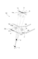
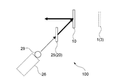
- FIG. 1 is a schematic diagram showing a basic configuration of an image display device according to a first embodiment of the present technology.
- 1A and 1B are a side view and a top view of the image display device 100.
- the image display device 100 is a device that three-dimensionally displays the virtual image 1 to be displayed to the users around the device.
- images (virtual images 1) of viewing objects viewed from various viewpoints 2 are displayed according to the positions of the viewpoints 2. Therefore, when the user's viewpoint 2 moves, it is possible to observe the virtual image 1 representing the display target as seen from the moved viewpoint 2.
- the virtual image surface 3 on which the virtual image 1 is formed is schematically illustrated by a dotted line region.
- the image display device 100 includes a plurality of virtual image screens 10, a multi-viewpoint video source 11, and a video control unit 12.
- the image to be displayed displayed by the multi-viewpoint video source 11 is displayed as a virtual image 1 by the virtual image screen 10.
- the image displayed on the multi-viewpoint video source 11 is controlled by the video control unit 12.
- the image includes a still image and a moving image (video).
- the direction of the surface on which the image display device 100 is arranged will be described as the horizontal direction, and the direction perpendicular to the horizontal direction will be described as the vertical direction.
- the plurality of virtual image screens 10 are arranged so as to cover at least a part around the central axis O.
- the central axis O is, for example, an axis that serves as a reference when displaying the virtual image 1.
- the central axis O is typically set parallel to the vertical direction.
- a plurality of virtual image screens 10 are arranged so as to partially surround the central axis O.
- the present technology can also be applied to a configuration in which a plurality of virtual image screens 10 are arranged so as to cover the entire circumference of the central axis O (see FIG. 10 and the like).
- the central axis O corresponds to a predetermined axis.
- the virtual image screen 10 displays the virtual image 1 of the image projected on each virtual image screen 10 with the central axis O as a reference.
- the virtual image screen 10 is transparent.
- a viewpoint image 4 which is a real image displayed by the multi-viewpoint image source 11 is projected on each virtual image screen 10.
- the virtual image 1 of the viewpoint image 4 is displayed with reference to the central axis O. Therefore, the virtual image screen 10 superimposes the virtual image 1 of the viewpoint image 4 displayed by the multi-viewpoint image source 11 on the background with the central axis O as a reference.
- a holographic optical element (HOE: Holographic Optical Element) is used as the virtual image screen 10.
- the HOE is an optical element using hologram technology, and realizes control of the traveling direction of light (optical path control) by diffracting light by interference fringes recorded in advance.
- a HOE configured to emit light incident at a predetermined incident angle at a predetermined emission angle is used as the virtual image screen 10.
- the light incident on the HOE (virtual image screen 10) can be emitted in a desired direction.
- the HOE may have the characteristics of a plane mirror and a curved mirror in order to control the position of the virtual image 1.
- a reflective holographic optical element (reflective HOE) is used as the virtual image screen 10.
- the reflective HOE is configured to diffract and reflect light incident in a specific angle range and transmit light in another angle range. For example, light incident on a reflective HOE in a specific angle range is emitted from a surface incident at an emission angle corresponding to the incident angle. Further, light incident at an incident angle other than a specific angle range passes through the reflective HOE with almost no diffraction due to interference fringes.
- the transparent virtual image screen 10 is configured, and the virtual image superimposed on the background can be displayed through the virtual image screen 10. In this way, the virtual image screen 10 functions as a combiner that superimposes and displays the virtual image 1 to be displayed on the background.
- the virtual image screen 10 is configured by using, for example, a volumetric HOE in which interference fringes are recorded inside the element. Further, a relief type (embossed type) HOE or the like in which interference fringes are recorded due to irregularities on the surface of the element or the like may be used as the virtual image screen 10. These HOEs are examples of diffractive optical elements (DOEs). As described above, the virtual image screen 10 is configured by using the diffractive optical element. In addition to the HOE that records interference fringes and diffracts light, a diffractive optical element of a type that diffracts light using a diffraction grating or the like having a predetermined pattern may be used.
- DOEs diffractive optical elements
- the specific configuration of the virtual image screen 10 is not limited.
- a half mirror may be used as the virtual image screen 10. Even when a half mirror is used, the virtual image 1 of the viewpoint image 4 can be superimposed and displayed on the background. The reflection by the half mirror is specular. Therefore, in the configuration in which the half mirror (virtual image screen 10) is vertically arranged as shown in FIG. 1, the viewing range of the virtual image 1 is a range in which the half mirror is viewed from diagonally above.
- any optical element capable of displaying a virtual image may be used as the virtual image screen 10.
- the virtual image screen 10 has a flat plate shape having a rectangular shape in a plan view, and has a front surface 13 and a back surface 14 which are opposite surfaces to each other.
- the virtual image screens 10 are arranged adjacent to each other at a predetermined angle with their back surfaces 14 facing the central axis O.
- Each virtual image screen 10 displays the virtual image 1 on the back surface 14 side facing the central axis O.
- each virtual image screen 10 is arranged parallel to the central axis O (vertical direction).
- the virtual image screens 10 may be arranged so as to be inclined with respect to the central axis O.
- three virtual image screens 10a to 10c are arranged adjacent to each other in this order from the left side.
- the plurality of virtual image screens 10 form a multi-faceted screen with the central axis O as a reference.
- the virtual image 1 of the viewpoint image 4 is displayed inside the multi-faceted screen (on the O side of the central axis).
- the multi-sided screen is a screen including a polygonal surface (for example, a polygonal surface constituting a regular polygonal prism) internally provided in a cylindrical surface centered on the central axis O.
- the multi-viewpoint video source 11 has a plurality of multi-viewpoint displays 20.
- the multi-viewpoint display 20 has a flat plate shape having a rectangular plan view, and has a display surface 21 for displaying the viewpoint image 4.
- the viewpoint image 4 displayed changes according to the viewing direction of the display surface 21.
- Each multi-view display 20 is arranged adjacent to each other at a predetermined angle with each display surface 21 facing the surface 13 of the corresponding virtual image screen 10.
- the multi-view display 20 constitutes the multi-sided display with the central axis O as a reference.
- the multi-viewpoint displays 20a to 20c are arranged toward the three virtual image screens 10a to 10c, respectively.
- a display unit for displaying the virtual image 1 is configured by a pair of the virtual image screen 10 and the multi-viewpoint display 20.
- FIG. 1A shows a side view of a display unit including a virtual image screen 10 and a multi-view display 20 as viewed from the side.
- An image display device is configured by rotating such a display unit around the central axis O and arranging a plurality of display units.
- the multi-view display 20 is arranged at a position shifted downward from the front of the virtual image screen 10. That is, the display surface 21 (multi-viewpoint display 20) is arranged so as not to block the virtual image displayed by the plurality of virtual image screens 10. This makes it possible to expand the display range of the virtual image 1, for example. Therefore, the image display device 100 has a configuration in which a multi-faceted display composed of a plurality of multi-viewpoint displays 20 is arranged outside the multi-faceted screen composed of the plurality of virtual image screens 10 while avoiding the optical path of the virtual image 1.
- the multi-viewpoint video source 11 corresponds to a display unit.
- the virtual image 1 displayed via the virtual image screen 10 is composed of an image (viewpoint image 4) displayed on the display surface 21 of the corresponding multi-viewpoint display 20. That is, it can be said that the user observing the virtual image 1 is looking at the display surface 21 through the virtual image screen 10.
- the direction in which the user sees the multi-viewpoint display 20 through the virtual image screen 10 will be referred to as a real image observation direction.
- the direction from the user's viewpoint 2 toward the central axis O is described as the virtual image observation direction.
- the viewpoint image 4 displayed in the real image observation direction corresponding to the viewpoint 2 is observed as the virtual image 1.
- FIG. 2 is a schematic view showing an example of the viewpoint image 4.
- the viewpoint image 4 is an image capable of displaying a state in which the display target 5 is viewed from different directions as a virtual image. Therefore, the viewpoint image 4 does not have to be an image of the display target 5 as it is viewed.
- the reflective virtual image screen 10 is used. That is, the virtual image screen 10 reflects the viewpoint image 4 projected from the display surface 21 to display the virtual image 1 of the viewpoint image 4. Therefore, the image displayed as the virtual image 1 is an image (mirror image inverted image) in which the left and right sides of the viewpoint image 4 displayed on the display surface 21 are inverted.
- the image control unit 12, which will be described later displays the viewpoint image 4 in which the image of the display target 5 viewed from the real image observation direction is mirror-inverted in the virtual image observation direction. As a result, it is possible to properly display the virtual image 1 of the display target 5 without inverting the left and right sides.
- FIG. 2A shows captured images 6a to 6c of a character (display target 5) holding a stick in his / her left hand, taken from the left side, the front side, and the right side.
- FIG. 2B shows viewpoint images 4a to 4c displaying the captured images 6a to 6c of FIG. 2A.
- the captured image 6 is an image obtained by capturing the character as it is.
- the viewpoint image 4 that reflects these and displays them as a virtual image is a mirror-inverted image in which the photographed image 6 is horizontally inverted. Therefore, the viewpoint images 4a to 4c are images in which the character to be displayed 5 holds the stick in his / her right hand.
- the viewpoint image 4 is generated based on, for example, an image of a stationary display target 5 taken by changing the shooting direction (shooting direction) without changing the shooting distance.
- the angle pitch for changing the shooting direction is typically set to a constant angle.
- the display target 5 may be an object existing in the real space, or a 3D model or the like generated by using computer graphics or the like.
- a deformed image or the like for correcting distortion or the like when displayed as a virtual image 1 may be used as the viewpoint image 4.
- a transmissive virtual image screen an image of the display target 5 as it is viewed is used as the viewpoint image 4.
- a plurality of viewpoint images 4 are switched and displayed on the display surface 21 of the multi-view display 20 according to the viewing direction. That is, the display surface 21 displays a plurality of viewpoint images 4 which are images of the display target 5 viewed from different directions.
- the direction in which each viewpoint image 4 is displayed from the display surface 21 (hereinafter, referred to as the display direction 7) is schematically illustrated by using black arrows.
- the display direction 7 is, for example, a direction in which light indicating the center of each viewpoint image 4 is emitted. Therefore, when the display surface 21 is directly viewed from the point where the display direction 7 is directed, an image composed of the image light emitted toward the display direction 7 is observed.
- the display surface 21 is configured to switch and display the viewpoint image 4 as shown in FIG. 2 for each of these display directions 7.
- a plurality of viewpoint images 4 displayed on each display surface 21 are projected onto each of the plurality of virtual image screens 10 by the plurality of display surfaces 21.
- a plurality of viewpoint images 4 are projected onto one virtual image screen 10 from one display surface 21 that is a pair in the display unit.
- the viewpoint image 4 is projected from a plurality of display surfaces 21 on one virtual image screen 10 or the viewpoint image 4 is projected from one display surface 21 on a plurality of virtual image screens 10. possible.
- a plurality of viewpoint images 4 are projected onto the virtual image screen 10.
- the virtual image screen 10 is displayed so that the virtual images 1 of the plurality of viewpoint images 4 are switched according to the viewing direction (position of the viewpoint 2) of the virtual image screen 10.
- the video control unit 12 controls the display of the viewpoint image 4 displayed on each multi-view display 20 (display surface 21) of the multi-view video source 11. Specifically, image data (video data) of the viewpoint image 4 displayed in each display direction is generated and displayed on each display surface 21.
- the video control unit 12 is configured by using a computer such as a PC or a server device. The operation of the video control unit 12 will be described later.
- the virtual image screen 10 and the multi-viewpoint display 20 are configured so that the virtual image plane 3 on which the virtual image 1 of each viewpoint image 4 is formed overlaps with each other about the central axis O. Will be done. This makes it possible to avoid a situation in which the position of the virtual image 1 of the display target 5 shifts depending on the viewing direction.
- the virtual image 1 does not necessarily have to overlap at the center.
- the multi-view display 20 is brought closer to the virtual image screen 10
- the virtual image surface 3 also approaches the virtual image screen 10.
- the viewpoint image 4 can be used for stereoscopic display. Therefore, the size of the display can be reduced by reducing the distance between the multi-view display 20 and the virtual image screen 10 within a range in which the virtual image 1 is connected.
- FIG. 3 is a schematic diagram for explaining a three-dimensional display by the image display device 100.
- a method of displaying the viewpoint image 4 for performing stereoscopic display will be described with reference to FIG.
- the virtual image 1 is observed through the two virtual image screens 10a and 10b by the user who points the viewpoint 2 toward the central axis O.
- the virtual image 1 observed by the user is a composite image of the virtual images 1a and 1b of the viewpoint images 4 displayed on the multi-viewpoint displays 20a and 20b.
- the user When the user attempts to view a display object through two virtual image screens 10a and 10b adjacent to each other, the user displays the display surfaces 21 of the two multi-viewpoint displays 20a and 20b reflected by the virtual image screens 10a and 10b, respectively. You will see it from a different angle. That is, the angle at which the user views each display surface 21 through the virtual image screen 10, that is, the direction in which the user looks at each display surface 21 is different from each other.
- the real image observation directions 8a and 8b directed to the multi-viewpoint displays 20a and 20b are schematically illustrated by white arrows.
- the virtual image observation direction 9 directed from the user's viewpoint 2 toward the central axis O is schematically illustrated by black arrows.
- the real image observation direction 8 corresponds to the first direction
- the virtual image observation direction 9 corresponds to the second direction.
- the image control unit 12 allows the central axis O from the user's viewpoint 2 with respect to the real image observation direction 8 in which the display surface 21 is viewed from the user's viewpoint 2 around the virtual image screen 10 through the virtual image screen 10.
- a viewpoint image 4 which is a virtual image of the display target 5 viewed from the virtual image observation direction 9 toward the display is displayed. That is, the viewpoint image 4 displayed from a certain viewpoint 2 toward the real image observation direction 8 in which the display surface 21 is expected is an image that displays the state of the display object 5 to be observed from the viewpoint 2 as a virtual image 1.
- the image control unit 12 displays a viewpoint image 4 that displays a display target 5 that can be seen from the user's viewpoint 2 (virtual image observation direction 9) with respect to the real image observation directions 8a and 8b that the user expects the display surfaces 21a and 21b. It is displayed on each display surface 21a and 21b.
- the viewpoint image 4 is displayed on each of the display surfaces 21a and 21b so that the central axes of the display target 5 displayed as the virtual image 1 are aligned with each other.
- the image of the display target 5 seen from the user's viewpoint 2 can be properly displayed as a virtual image.
- the viewpoint 2 (the viewpoint 2 () with respect to the real image observation direction 8 directed to the corresponding display surface 21.
- the viewpoint image 4 which is a virtual image of the display target 5 seen from the virtual image observation direction 9) is displayed.
- the display target 5 can be observed from multiple directions for each virtual image screen 10.
- the image display device 100 can display each viewpoint image of the display target 5 with an angular resolution corresponding to the angle pitch displayed by the multi-viewpoint image source 11 regardless of the position of the user's viewpoint 2. ..
- the image control unit 12 displays the viewpoint image 4 so that the virtual image of the display target 5 as viewed from the viewpoint 2 is switched at a predetermined angle pitch according to the movement of the viewpoint 2 of the user.
- the viewpoint image 4 that switches at a constant angle when the user moves, and it is possible to realize a natural stereoscopic display.
- the method of setting a predetermined angle pitch is not limited.
- the angle pitch is set so that the angle formed by a straight line horizontally connecting both ends of the virtual image screen 10 (multi-viewpoint display 20) from the central axis O (the central angle of the polygonal surface) is divided by an integer.
- the viewpoint image 4 can be smoothly switched even at the boundary of the adjacent virtual image screens 10.
- the angle pitch may be set according to the number of viewpoint images 4 that can be displayed on the multi-view display 20.
- the image display device 100 a plurality of viewpoint images 4 displayed on the display surface 21 of the multi-viewpoint image source 11 are projected onto the virtual image screen 10.
- the virtual image of the viewpoint image 4 can be switched and displayed for each virtual image screen 10.
- the image display device 100 is configured by arranging a plurality of display units including a virtual image screen 10 and a multi-viewpoint display 20 around the central axis O. By arranging in this way, when the virtual image screen 10 is viewed from multiple directions, the virtual image surface 3 on which the virtual image 1 is formed can be kept within a certain range, and the virtual image 1 can be observed without interruption. .. This makes it possible to significantly improve the motion parallax recognized as the user moves.
- the virtual image screen 10 (combiner) of HOE, it is possible to sufficiently improve the transparency and the brightness as compared with, for example, the Pepper's ghost type virtual image display using a half mirror.
- the virtual image screen 10 can be arranged upright in the vertical direction. Therefore, the horizontal width of the screen can be kept constant, and the virtual image 1 can be displayed in a wide display range. This makes it possible to display a large and bright virtual image 1 superimposed on the background through a highly transparent screen. This makes it possible to realize a stereoscopic display with a high sense of reality.
- FIG. 4 is a schematic diagram showing a specific configuration example of the image display device 100.
- 5 and 6 are a side view and a top view of the image display device 100 shown in FIG.
- a multi-projector type display is used as the multi-viewpoint display 20 of the multi-viewpoint video source 11.
- the multi-viewpoint video source 11 has a plurality of real image screens 25 and a plurality of projectors 26.
- a plurality of projectors 26 are provided for each real image screen 25 to form a projector array.
- the real image screen 25 and the projector array function as the multi-view display 20 described above.
- the real image screen 25 is a transmissive anisotropic diffusion screen, and has a projection surface 27 on which an image is projected from each projector 26 and an image display surface 28 on the opposite side of the projection surface.
- the image display surface 28 becomes the display surface 21 described above.
- the plurality of real image screens 25 are arranged on the corresponding virtual image screens 10 so as to face the image display surface 28 (display surface 21).
- the real image screen 25 has anisotropic diffusion characteristics in which the diffusivity differs between the horizontal direction and the vertical direction. For example, the degree of diffusion in the horizontal direction is set to be smaller than that in the vertical direction, and is configured to have a narrow diffusion characteristic with respect to the horizontal direction.
- the angle range of the light diffused in the horizontal direction can be narrowed, and the plurality of viewpoint images 4 can be emitted in a desired direction.
- the viewpoint image 4 can be projected in the vertical direction without widening the angle of incidence on the virtual image screen 10.
- the real image screen 25 a reflective type and arrange the projectors 26 inside the device (see FIG. 10 and the like).
- the real image screen 25 is composed of a lens diffuser or the like whose diffusion degree is biased in the horizontal and vertical directions by, for example, a microlens array or the like. Further, a transmission type HOE in which the anisotropic diffusion characteristics are recorded may be used as the real image screen 25.
- HOE transmission type HOE in which the anisotropic diffusion characteristics are recorded
- the projection angle of the projector 26 with respect to the real image screen 25 can be reduced while maintaining the incident angle with respect to the virtual image screen 10. This makes it possible to reduce the size of the entire multi-viewpoint video source 11. Further, since it is easy to control the diffusion characteristics in HOE, it is possible to display the viewpoint image 4 having better image quality.
- the plurality of projectors 26 project images constituting the viewpoint image 4 on the projection surface 27 of the real image screen 25.
- the plurality of projectors 26 project images onto the real image screen 25 from different directions.
- each projector is arranged so that the light emitting point 29 of the projector 26 is on the circumference with respect to the center of the real image screen 25.
- a projector module in which a plurality of light emitting points 29 are integrated so as to be arranged in a circumferential shape may be used.
- each projector 26 projects an image from diagonally below the real image screen 25. This projection angle is set according to, for example, the projection angle of the display surface 21 with respect to the virtual image screen 10.
- An image is projected on the projection surface 27 of the real image screen 25 by these projectors 26, and the viewpoint image 4 is displayed on the display surface 21.
- the pixel light constituting each pixel of the image displayed on the real image screen 25 is emitted according to the direction of incident on the projection surface 27.
- a part of the images (typically strip-shaped images) projected by each of the plurality of projectors 26 can be combined to display a plurality of viewpoint images 4 in each display direction. It will be possible.
- FIG. 4 schematically shows a plurality of viewpoint images 4 viewed from the projection surface 27 side.
- the angle pitch at which the plurality of projectors 26 project an image on the real image screen 25 is the angle pitch (viewpoint pitch) of the viewpoint image 4 that can be displayed by the multi-viewpoint image source 11.
- this angle pitch smaller than the parallax angle of both eyes, it is possible to display different viewpoint images 4 for both eyes of the user to give binocular parallax, and it is possible to reproduce the stereoscopic effect of the display target. It becomes.
- Even when the angle pitch is rough it is possible to give motion parallax to the display target 5 and make it appear three-dimensional by switching and displaying the viewpoint image 4 according to the movement of the viewpoint position of the user. ..
- the diffusion angle of the real image screen 25 in the horizontal direction is equal to the angular pitch of the projector 26. This makes it possible to avoid crosstalk or the like in which the viewpoint images 4 to be displayed in different directions are observed at the same time.
- the range of the entire projection angle at which the plurality of projectors 26 project an image on the real image screen 25 is the viewing range (viewable angle) of the viewpoint image that can be displayed on the real image screen 25. Therefore, for example, in order to display the display target 5 without being cut off, it is desirable to project the image at an angle as large as possible. For example, it is possible to widen the overall projection angle by increasing the projection angle of view of each projector 26.
- the viewpoint image 4 can be displayed using colored light having a narrow wavelength width, and the diffraction efficiency in the HOE (virtual image screen 10 or real image screen 25) can be improved and the display brightness can be increased.
- an LED light source may be used as the light source of the projector 26.
- the specific configuration of the projector 26 is not limited.
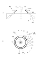
- FIG. 7 is a schematic diagram for explaining a method of displaying a viewpoint image projected on the reflective virtual image screen 10.
- the user is observing the virtual image along the virtual image observation direction 9 passing through the boundary between the virtual image screens 10a and 10b adjacent to each other.
- the direction from the central axis O toward the boundary is set as the starting point direction which is the starting point when the display target 5 is displayed.
- the starting point direction is, for example, the direction in which the front surface of the display target 5 is directed.
- the direction of clockwise rotation with respect to the central axis O is defined as the positive direction of the azimuth angle.
- the starting point direction of the display target 5 (for example, the direction of observing the front of the display target 5 (virtual image)) is represented by an azimuth angle with respect to the central axis O.
- the azimuth in the starting point direction is ⁇ 0 degrees. Therefore, in FIG. 7, the virtual image 1 is observed from the viewpoint 2 in which the virtual image observation direction 9 has an azimuth angle ⁇ 0.
- the angle at which the center of the real image screen 25a on the left side when viewed from the user's viewpoint 2 is seen is ⁇ i1 .
- the angle at which the center of the real image screen 25b on the right side when viewed from the user's viewpoint 2 is seen is ⁇ i2 .
- ⁇ i1 and ⁇ i2 will be described as angles in the horizontal plane.
- ⁇ i1 ( ⁇ i2 ) a straight line that projects an optical path toward the center of the real image screen 25a (real image screen 25b) via the virtual image screen 10a (real image screen 10b) onto a horizontal plane is the real image screen 25a (real image screen 25b). It is the angle formed with the normal line of.
- These angles can be said to represent the directions in which the real image screens 25a and 25b are expected (real image observation directions 8a and 8b).
- the angle ⁇ i1 in which the real image screen 25a is expected is ( ⁇ i1- ⁇ ( ⁇ ) ⁇ ⁇ ).
- ⁇ ( ⁇ ) is a positive coefficient.
- ⁇ i1 decreases as the viewpoint 2 moves by ⁇ . This means that the direction in which the real image screen 25a seen from the upper surface is seen rotates counterclockwise.
- the angle ⁇ i2 in which the real image screen 25b is expected is ( ⁇ i2 + ⁇ ( ⁇ ) ⁇ ⁇ ).
- ⁇ ( ⁇ ) is a positive coefficient.
- ⁇ i1 increases as the viewpoint 2 moves by ⁇ . This means that the direction in which the real image screen 25b seen from the upper surface is seen rotates counterclockwise.
- the viewpoint image 4 of the display target 5 of ⁇ 0 + ⁇ degree is displayed on each display surface 21 so that the user can see from there. It is possible to show a virtual image of the display target 5.
- ⁇ ( ⁇ ) is a coefficient related to the amount of change in the angle ⁇ i1 that looks into the real image screen 25a on the left side when viewed from the viewpoint 2, and ⁇ ( ⁇ ) looks into the real image screen 25b on the right side when viewed from the viewpoint 2. It is a coefficient related to the amount of change in the angle ⁇ i2. These coefficients are parameters for correcting the effects of projection angle conversion, lens effect, HOE diffraction aberration, etc. (angle deviation, etc.), and are expressed as a function of the azimuth angle ⁇ of the viewpoint 2 with respect to the azimuth angle ⁇ 0. Will be done. By correcting the amount of change using such a coefficient, it is possible to correctly display the virtual image 1 of the display target 5.
- FIG. 8 is a schematic view showing an example of a viewpoint image displayed according to the observation direction.
- a viewpoint image displayed according to the observation direction.
- an image of a character (display target 5) holding a stick in the left hand as viewed from the front is displayed.
- a character holding a stick in the right hand is displayed as the viewpoint images 4a and 4b in the real image observation directions 8a and 8b.
- FIG. 8 shows viewpoint images 4a and 4b observed when the real image screens 25a and 25b are viewed from the front side along the real image observation directions 8a and 8b.
- the characters rotated counterclockwise are reflected on the real image screens 25a and 25b.
- the viewpoint images 4a and 4b are displayed.
- the viewpoint images 4a and 4b showing the character rotated clockwise are displayed on the real image screens 25a and 25b.
- the display target 5 rotated in the direction opposite to the movement of the user is displayed on the display surface 21 of the real image screen 25. To. As a result, the display target 5 can be properly displayed according to the movement of the user.
- a plurality of transparent virtual image screens 10 are arranged so as to cover at least a part around the central axis O. Further, a plurality of display surfaces 21 for displaying the plurality of viewpoint images 4 of the display target 5 in different directions are provided. A plurality of viewpoint images 4 are projected on each virtual image screen 10. At this time, in the direction in which the display surface 21 is viewed from a certain viewpoint 2 via the virtual image screen 10 (real image observation direction 8), the viewpoint becomes the virtual image 1 of the display target 5 that can be seen when the central axis O is viewed from the viewpoint 2. Image 4 is displayed. This makes it possible to realize a stereoscopic display with a high sense of reality.
- Pepper's ghost As a method of displaying an object using a virtual image, a method called Pepper's ghost is known in which a half mirror is tilted with respect to the horizontal to display a virtual image of the object.
- a viewpoint image in which the viewing direction of the object changes according to the movement of the user, and the object.
- the sense of reality may be impaired.
- Another possible method is to make the half mirror multi-faceted to display the object in three dimensions. In this case, when crossing adjacent surfaces, the images are switched violently, which may impair the sense of reality.
- the size of the reflecting surface may be reduced and the image size may be reduced by increasing the number of surfaces.
- FIG. 9 is a schematic view of the virtual image display device 90 shown as a comparative example.
- a virtual image display device 90 that displays a virtual image 1 using the HOE 91 is schematically shown.
- an image of the target 92 viewed from one direction is projected onto the HOE 91 arranged in a polygonal columnar shape. Therefore, when the user's line of sight crosses the boundary of the HOE 91, the image of the target 92 changes abruptly, which may impair the realism of the stereoscopic display.
- the viewpoint image of the display target 5 is projected on each of the plurality of virtual image screens 10.
- a viewpoint image of the display target 5 viewed from multiple directions is displayed for each virtual image screen 10.
- the plurality of virtual image screens 10 are arranged so as to surround the central axis.
- the viewpoint image 4 is displayed so that the display target seen from the viewpoint 2 is displayed in the direction in which the user's viewpoint 2 sees the display surface 21 through the virtual image screen 10 (virtual image observation direction 9). That is, the display of the display surface 21 is controlled so that the viewpoint image 4 of the display target viewed from that direction is formed according to the difference in the observation direction of each virtual image surface 3 viewed from the user. This makes it possible to properly display the virtual image 1 of the display object 5 to be observed from that viewpoint regardless of the position of the viewpoint 2.
- HOE is used as the virtual image screen 10. This makes it possible to arrange the virtual image screen 10 upright in the vertical direction. As a result, it is possible to improve the reproducibility of the viewpoint image 4 of the display target 5 including the case of crossing the boundary of the virtual image screen 10 without reducing the image size, and it is possible to realize a stereoscopic display with a sense of reality. It will be possible.
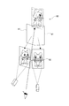
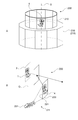
- FIG. 10 is a schematic diagram showing a configuration example of the image display device according to the second embodiment.
- 10A is a perspective view of the image display device 200
- FIG. 10B is a schematic view showing an example of the internal configuration of the image display device 200.
- 11 and 12 are a cross-sectional view and a top view of the image display device 200 shown in FIG.
- the image display device 200 has a plurality of virtual image screens 210 and a multi-viewpoint image source 211, and functions as an omnidirectional display capable of displaying a virtual image 1 when the display target 5 is viewed from all directions.
- the plurality of virtual image screens 210 are arranged so as to cover the entire circumference of the central axis O. These virtual image screens 210 form a polygonal multi-faceted screen with reference to the central axis O.
- the virtual image screen 210 is a reflective holographic optical element (HOE). Therefore, in the image display device 200, the virtual image 1 of the viewpoint image 4 of the display target 5 projected from the outside of the multi-faceted screen is displayed inside the multi-faceted screen.
- the HOE may have the characteristics of a plane mirror and a curved mirror in order to control the position of the virtual image 1.
- the multi-viewpoint video source 211 has a plurality of real image screens 230 and a plurality of projectors 231 that project images onto the real image screens 230 from different directions.
- the real image screen 230 and the plurality of projectors 231 constitute a multi-viewpoint display.
- the real image screen 230 is a reflective anisotropic diffusion screen. Therefore, in the real image screen 230, the surface on which the image is projected from each projector 231 is the display surface 221 (image display surface) on which the viewpoint image 4 is displayed.
- the plurality of real image screens 230 are arranged so that the display surface 221 faces the corresponding virtual image screen 210.
- These real image screens 230 constitute a polygonal columnar multi-sided display with reference to the central axis O.
- the real image screen 230 has anisotropic diffusing characteristics in which the diffusivity differs in the horizontal direction and the vertical direction, and is configured by, for example, attaching a reflecting plate to a transmissive lens diffusing plate. Further, a reflective HOE in which the anisotropic diffusion characteristics are recorded may be used as the real image screen 230. By using HOE, it is possible to reduce the size of the entire multi-viewpoint video source 211 and display the viewpoint image 4 with good image quality.
- the plurality of projectors 231 project images from the inside of the plurality of real image screens 230 (multi-faceted displays) arranged around the central axis O toward each display surface 221.
- a laser light source or an LED light source is used as the light source of the projector 231.
- the wavelength width of the colored light may be limited by using a wavelength filter or the like.
- FIG. 10B schematically shows a display unit including a reflective virtual image screen 210 and a reflective real image screen 230 as an example of the internal configuration of the image display device 200.
- a projector array composed of a plurality of projectors 231 is provided inside the real image screen 230.
- FIG. 10B it is possible to use a configuration in which an image is directly projected from each projector 231 onto the real image screen 230. is there.
- FIG. 11 schematically shows a cross-sectional view of the image display device 200 cut along a cross section including the central axis O.
- FIG. 12 schematically shows a top view corresponding to the configuration shown in FIG. In FIGS. 11 and 12, the image is projected onto the real image screen 230 in a manner different from that in FIG. 10B.
- the projector 231 is arranged outward and upward along the outer circumference of the device.
- the light of the image projected from the projector 231 is reflected through a mirror (not shown) and is incident on the real image screen 230 arranged on the side opposite to the side on which the projector 231 is arranged. That is, an image is projected onto each real image screen 230 from a light emitting point 29 (mirror) on the opposite side of the central axis O. This makes it possible to increase the projection distance and increase the size of the projected image.
- each projector 231 is arranged so that its light emitting points 29 are lined up along the circumference which is the outer circumference of the device.
- the integrated projector module may be configured so that a plurality of light emitting points are arranged along the outer circumference.
- the angle pitch at which the plurality of projectors 231 project an image onto the real image screen 230 is the angle pitch (viewpoint pitch) of the viewpoint image 4 that can be displayed by the multi-viewpoint image source 211.
- the angle pitch sufficiently small, it is possible to perform stereoscopic display that gives binocular parallax.
- the range of the entire projection angle at which the plurality of projectors 231 project the image on the real image screen 230 is the viewing range (viewable angle) of the viewpoint image that can be displayed on the real image screen 230. Therefore, by increasing the projection angle of view of each projector 231, it is possible to display the display target 5 without being cut off.
- a configuration in which the light emitted from one projector 231 is divided and projected may be used. By split projection, it is possible to create a plurality of light emitting points 29 from one projector 231.
- FIG. 13 is a schematic diagram showing an example of divided projection.
- three division mirrors 235a to 235c that divide the image projected by the projector 231 are used.
- the image projected from the projector 231 is divided by the divided mirrors 235a to 235c, and is divided into three directions and projected as a divided image while being enlarged.
- each of the divided mirrors 235a to 235c can be regarded as a light emitting point for projecting the divided image.
- the number of split mirrors 235 is not limited. By using the split mirror 235, the number of projectors 231 can be reduced, and the cost of the apparatus can be suppressed.
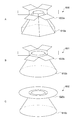
- FIG. 14 is a schematic view showing an example of the display position of the virtual image 1 in the image display device 200.
- 14A to 14C schematically show an example of the display position of the virtual image 1 of the viewpoint image 4 displayed by the multi-viewpoint image source 211.
- the virtual images 1 of the plurality of viewpoint images 4 are displayed so that the center lines of the virtual image planes 3 overlap each other.
- the center line of the virtual image plane 3 is a center line parallel to the vertical direction (center axis O).
- the centerline of each virtual image plane 3 is displayed so as to coincide with the central axis O.
- the virtual images 1 of the plurality of viewpoint images 4 are displayed so that a part of the virtual image surfaces 3 overlap each other.
- the virtual image 1 does not necessarily have to be centered, and may be partially overlapped.
- the multi-viewpoint image source 211 real image screen 230
- the device can be miniaturized.
- the image display device 200 can display the virtual image 1 so that the image of the display target 5 is observed before and after the virtual image surface 3. Therefore, even when the virtual image planes 3 do not overlap with each other on the central axis O, the virtual image can be displayed with the central axis O as a reference by displaying the virtual image 1 on the back side.
- the virtual images 1 of the plurality of viewpoint images 4 are displayed so that the virtual image surfaces 3 are in contact with each other.
- the distance between the real image screen 230 and the virtual image screen 210 can be sufficiently shortened, and for example, a substantially tubular image display device having a small step on the side surface can be realized.
- FIG. 15 is a schematic view showing another configuration example of the image display device.
- a transmissive real image screen 240 is used instead of the reflective real image screen.
- 15A and 15B are a cross-sectional view and a top view of an image display device 201 equipped with a transmissive real image screen 240.
- the projector 231 is arranged outside the real image screen 240, and an image is directly projected from each projector 231.
- FIG. 15B by providing the projector 231 outside the real image screen 240, the degree of freedom in arranging the projector 231 is improved, and it is easy to project an image from one projector 231 to a plurality of real image screens 240. It is possible to realize.
- FIG. 16 is a schematic view showing a configuration example of the image display device according to the third embodiment.
- 16A is a perspective view of the image display device 300
- FIG. 16B is a schematic view showing an example of the internal configuration of the image display device 300.
- 17 and 18 are side views and top views of the image display device 300 shown in FIG.
- an omnidirectional display is configured by using a direct-view stereoscopic display 340.
- the image display device 300 has a plurality of virtual image screens 310 and a multi-viewpoint image source 311 composed of a plurality of stereoscopic display 340s.
- Each virtual image screen 310 is configured in the same manner as the virtual image screen 210 of the image display device 200 described with reference to, for example, FIG. That is, the virtual image screen 310 is a reflective HOE and is arranged so as to cover the entire circumference of the central axis O.
- the stereoscopic display 340 is a direct-view type display capable of displaying a stereoscopic image without using dedicated glasses or the like.
- the stereoscopic display 340 has an image display surface 341 for displaying a stereoscopic image.
- a direct-view stereoscopic display generally displays a stereoscopic image by displaying a plurality of viewpoint images 4 in a plurality of display directions. Therefore, in the present embodiment, the image display surface 341 of the direct-view stereoscopic display 340 is the display surface for displaying the viewpoint image 4.
- Each stereoscopic display 340 is arranged with the image display surface 341 facing the corresponding virtual image screen 310. As shown in FIGS. 16 to 18, it can be said that the image display device 300 has a configuration in which the real image screen 230 of the image display device 200 shown in FIG. 10 or the like is replaced with a stereoscopic display 340.
- the stereoscopic display 340 displays a plurality of viewpoint images 4 by any one of a lenticular lens method, a lens array method, and a parallax barrier method.
- the lenticular lens method is a method of displaying images in different directions by using a lenticular lens that disperses light in the horizontal direction. By using the lenticular lens method, it is possible to display a brighter viewpoint image 4 as compared with the parallax barrier method or the like.
- the lens array method is a method of displaying the viewpoint image 4 by dispersing light in the vertical and horizontal directions using a microlens array. By using the lens array method, it is possible to increase the number of viewpoints in the vertical direction, and it is possible to express with a high sense of reality.
- the parallax barrier method is a method of displaying the viewpoint image 4 by using a parallax barrier or the like that selectively blocks the light of each pixel, and can realize a wider viewing angle as compared with other methods.
- the original image of the viewpoint image 4 is displayed by a flat panel display such as an LCD (Liquid Crystal Display).
- the light source used for the backlight of the display is preferably a laser light source.
- the wavelength width is narrowed by using a wavelength filter or the like to reduce image blurring and color shift due to color dispersion on the virtual image screen 310 (HOE).
- HOE virtual image screen 310
- any method capable of three-dimensional display with the naked eye may be used.
- the stereoscopic display 340 does not necessarily have to display the viewpoint image 4 at an angle pitch capable of stereoscopic viewing.
- a multi-viewpoint display may be used that displays a viewpoint image at a level at which binocular parallax does not occur.
- the image display device 300 includes a polygonal prism type multi-sided screen (virtual image screen 310) and a polygonal pillar-shaped multi-sided display (stereoscopic display device) arranged around the polygonal pillar type multi-sided screen (virtual image screen 310).
- a polygonal prism type multi-sided screen virtual image screen 310
- a polygonal pillar-shaped multi-sided display stereoscopic display device arranged around the polygonal pillar type multi-sided screen (virtual image screen 310).
- the image display device 300 includes a polygonal prism type multi-sided screen (virtual image screen 310) and a polygonal pillar-shaped multi-sided display (stereoscopic display device) arranged around the polygonal pillar type multi-sided screen (virtual image screen 310).
- FIG. 19 is a schematic view showing a configuration example of the image display device according to the fourth embodiment.
- the left and right views of FIG. 19 are a cross-sectional view and a top view of the image display device 400.
- a transmission type holographic optical element transmission type HOE
- transmission type HOE transmission type HOE
- the transmissive HOE is configured to diffract and transmit light incident in a specific angle range and transmit light in other angle ranges. For example, light incident on a transmissive HOE in a specific angle range is transmitted through the HOE main body and emitted from a surface opposite to the surface on which the light is incident at an emission angle corresponding to the incident angle. Further, light incident at an incident angle other than a specific angle range passes through the transmissive HOE with almost no diffraction due to interference fringes.
- the plurality of virtual image screens 410 are arranged so as to cover the entire circumference of the central axis O, and form a polygonal columnar multifaceted screen.
- the viewpoint image 4 is projected onto the back surface 414 of the virtual image screen 410 from diagonally below.
- the light constituting the viewpoint image 4 projected on the back surface 414 is emitted along the horizontal direction toward the front surface 413 of the virtual image screen 410.
- the user observing the virtual image screen 410 observes the virtual image 1 of the viewpoint image 4 on an extension line extending the optical path of the light emitted toward the front surface 413 toward the back surface 414.
- the image display device 400 and the virtual image planes 3 forming the virtual image 1 of each viewpoint image 4 are configured to intersect at the central axis O.
- the virtual image screen 410 is a transmissive mirror (transmissive mirror HOE) that transmits an image and displays it as a virtual image.
- a virtual image screen 410 configured as a transmissive planar mirror is used. It is also possible to configure the virtual image screen 410 as a transmissive curved mirror in which the HOE has a lens function (see FIG. 22).
- the virtual image screen 410 is configured using a single transmissive HOE.
- the virtual image screen 410 may be formed by joining two reflective HOEs. In this case, transmission can be realized by diffraction reflection twice.
- the virtual image screen 410 a transmissive type, for example, the multi-viewpoint image source 411 can be inserted inside the device more than the virtual image screen 410, and the device can be miniaturized.
- the virtual image screen 410 may be arranged so as to cover a part of the periphery of the central axis O.
- the multi-viewpoint video source 411 has a plurality of multi-viewpoint displays 420.
- the multi-view display 420 is arranged so as to cover the entire circumference of the central axis O, and constitutes a polygonal columnar multi-sided display.
- the virtual image screen 410 is a transmissive type. Therefore, the multi-viewpoint display 420 needs to project the viewpoint image 4 from diagonally below with respect to the back surface 414 of the virtual image screen 410, for example. Therefore, in the image display device 400, the multi-view display 420 is arranged at a position closer to the central axis O than the virtual image screen 410.
- the multi-viewpoint display 420 it is possible to use the multi-projector type real image screen described in the above embodiment or the direct-view type stereoscopic display.
- the transmissive virtual image screen 410 when used, the distance between the multi-view display 420, which is the image source, and the virtual image screen 410 becomes close, so that the virtual image 1 is the central axis O. It can be difficult to display them so that they overlap with each other. Even in such a case, it is possible to display the display target 5 from multiple viewpoints by displaying the virtual images 1 viewed from each direction so as to be connected.
- FIG. 20 is a schematic diagram for explaining a display method of the viewpoint image 4 projected on the transmissive virtual image screen 410.
- the direction in which the user looks at the multi-view display 420 through the virtual image screen 410 real image observation direction 8
- the direction from the user's viewpoint 2 toward the central axis are shown by using white and black arrows. It is schematically illustrated.
- FIG. 20 it is assumed that the user is observing the virtual image along the virtual image observation direction 9 passing through the boundary between the virtual image screens 410a and 410b adjacent to each other.
- the direction from the central axis O toward the boundary is set as the starting point direction which is the starting point when the display target 5 is displayed.
- a transmissive virtual image screen 410 is used. That is, the virtual image screen 410 transmits the viewpoint image 4 projected from the display surface 421 and displays the virtual image 1 of the viewpoint image 4. Therefore, the viewpoint image 4 displayed on the display surface 421 becomes an image displayed as a virtual image 1 as it is.
- the image control unit (not shown) displays the viewpoint image 4 of the display target 5 viewed from the real image observation direction 8 in the virtual image observation direction 9. As a result, the virtual image 1 of the display target 5 can be properly displayed.
- the starting point direction of the display target 5 (for example, the direction of observing the front of the display target 5 (virtual image)) is represented by an azimuth angle with respect to the central axis O.
- the azimuth in the starting point direction is ⁇ 0 degrees. Therefore, in FIG. 20, the virtual image 1 is observed from the viewpoint 2 in which the virtual image observation direction 9 has an azimuth angle ⁇ 0.
- the angle at which the center of the multi-viewpoint display 420a on the left side when viewed from the user's viewpoint 2 is seen is ⁇ i1 .
- the angle at which the center of the multi-view display 420b on the right side when viewed from the user's viewpoint 2 is seen is ⁇ i2 .
- ⁇ i1 and ⁇ i2 will be described as angles in the horizontal plane.
- ⁇ i1 ( ⁇ i2 ) a straight line that projects an optical path toward the center of the multi-view display 420a (multi-view display 420b) via the virtual image screen 410a (virtual image screen 410b) onto a horizontal plane is a multi-view display 420a (multi-view display 420a). It is an angle formed with the normal of the viewpoint display 420b).
- These angles can be said to represent the directions in which the multi-viewpoint displays 420a and 420b are expected (real image observation directions 8a and 8b).
- the user's viewpoint 2 moves by ⁇ and the azimuth angle of the virtual image observation direction 9 becomes ( ⁇ 0 + ⁇ ). That is, it is assumed that the viewpoint 2 is rotated clockwise with respect to the central axis O by ⁇ .
- the angle ⁇ i1 that looks into the multi-view display 420a is ( ⁇ i1- ⁇ '( ⁇ ) ⁇ ⁇ ).
- ⁇ '( ⁇ ) is a positive coefficient.
- ⁇ i1 decreases as the viewpoint 2 moves by ⁇ . This means that the direction in which the multi-viewpoint display 420a viewed from above is viewed rotates clockwise.
- the angle ⁇ i2 in which the multi-view display 420b is expected is ( ⁇ i2 + ⁇ '( ⁇ ) ⁇ ⁇ ).
- ⁇ '( ⁇ ) is a positive coefficient.
- ⁇ i2 increases as the viewpoint 2 moves by ⁇ . This means that the direction in which the multi-view display 420b viewed from above is viewed rotates clockwise.
- the viewpoint image 4 of the display target 5 of ⁇ 0 + ⁇ degree is displayed on each display surface 421 so that the user can see from there. It is possible to show a virtual image of the display target 5. Further, when the transmissive virtual image screen 410 is used, the direction in which the viewing direction rotates is opposite to that when the reflective virtual image screen 410 described with reference to FIG. 7 is used.
- ⁇ '( ⁇ ) and ⁇ '( ⁇ ) are coefficients related to the amount of change in the angles ( ⁇ i1 and ⁇ i2 ) for each multi-viewpoint display, such as projection angle conversion, lens effect, and HOE diffraction aberration. It is a parameter that corrects the influence of (angle deviation, etc.). In particular, when the lens function described below is provided, it is conceivable that the traveling direction of light changes significantly and aberration also occurs. By setting a coefficient and correcting the amount of change so as to reduce these effects, it is possible to correctly display the virtual image 1 of the display target 5.
- FIG. 21 is a schematic view showing an example of a virtual image displayed by a transmissive virtual image screen 410 having a lens function.
- the virtual image 1 is observed through the virtual image screen 410.
- the display position of the virtual image 1 and the size of the virtual image 1 are changed.
- the viewpoint 2 directed to the center of the lens there is no change in the direction of the optical path for displaying the virtual image.
- the direction in which the virtual image 1 is viewed changes due to the addition of the lens function.
- the direction in which the multi-viewpoint display 420 is viewed does not change even if the lens function is added.
- the optical path of the light displaying the virtual image 1 may change, and various aberrations may occur.
- the viewpoint image 4 is appropriately corrected so as to suppress such a change in angle and deformation due to aberration.
- FIG. 22 is a schematic view showing another configuration example of the image display device.
- the image display device 401 shown in FIG. 22A shows a configuration in which the virtual image screen 410 is provided with a lens function in the image display device 400 shown in FIG.
- this configuration by setting the display position of the virtual image 1 to a position far from the virtual image screen 410, it is possible to display the virtual image 1 so as to overlap with the central axis O. In this way, it is possible to appropriately adjust the display position of the virtual image 1 by using the lens function.
- the multi-sided screen composed of the virtual image screen 410 and the multi-sided display composed of the multi-viewpoint display 420 are configured to be internally installed in the same cylinder. Further, the viewpoint image 4 is projected on the virtual image screen 410 from the multi-viewpoint display 420 arranged on the opposite side of the central axis O. By projecting the image from the opposite side in this way, it is possible to increase the projection distance. Further, it is possible to realize a tubular image display device 400 having no step.
- FIG. 23 is a schematic view showing a configuration example of the image display device according to the fifth embodiment.
- the image display device 500 according to the present embodiment is configured by using a curved image screen 510.
- the image display device 500 has a cylindrical virtual image screen 510 and a cylindrical real image screen 525 having a radius larger than that of the virtual image screen 510.
- the virtual image screen 510 and the real image screen 525 are arranged about the central axis O, respectively.
- the real image screen 525 is arranged below the virtual image screen 510 so as not to block the display of the virtual image 1.
- the virtual image screen 510 and the real image screen 525 are composed of, for example, a reflective HOE.
- the image display device 500 has a plurality of projectors 526 that project images on the real image screen 525.
- FIG. 23 shows each light emitting point 29 of the plurality of projectors 526. It can be said that the image display device 500 has a cylindrical configuration in which the multi-sided screen (virtual image screen) and the multi-sided display (real image screen) of the image display device 200 described with reference to FIGS. 10 to 12 are formed into a cylinder.
- the plurality of projectors 526 are arranged so that the light emitting points 29 are arranged on the circumference along the real image screen 525. From each light emitting point 29, an image is projected toward the real image screen 525 on the opposite side of the central axis O. As a result, images are projected from the plurality of projectors 526 from different directions on the display surface 521 inside the real image screen 525, and the viewpoint image 4 can be displayed.
- the viewpoint image 4 displayed on the display surface 521 is projected on the virtual image screen 510.
- a cylindrical virtual image surface 3 centered on the central axis O is formed inside the virtual image screen 510.
- the virtual image of the display target 5 is displayed on the virtual image surface 3.
- the virtual image screen 510 When the virtual image screen 510 is made into a cylindrical shape, the virtual image surfaces 3 are in a connected state as shown in FIG. 23. Therefore, in the image display device 500, the seam of the virtual image screen 510 is eliminated. Therefore, the virtual image of the display target 5 can be displayed smoothly, and there is an effect of sufficiently improving the sense of reality. Further, the maximum value of the angle at which the virtual image screen 510 is seen is smaller than that when the polygonal columnar virtual image screen 510 is used.
- the angle at which the virtual image screen 510 is seen is, for example, an angle formed by the normal direction and the line-of-sight direction of the surface at the intersection of the line-of-sight directions with respect to the surface of the virtual image screen 510.
- the angle at which the virtual image screen 510 is seen changes continuously as the viewpoint 2 moves. Therefore, when the viewpoint 2 is moved, the decrease or fluctuation of the brightness, which tends to occur due to the switching of the surfaces, does not occur. As a result, it is possible to avoid a situation in which the brightness of the virtual image changes unnaturally and realize a natural stereoscopic display. These are the same even when the transmissive HOE is used as the virtual image screen 510.
- the real image screen 525 also has a cylindrical shape
- the present invention is not limited to this.
- the real image screen 525 may have a polygonal prism shape.
- the real image screen 525 may have a cylindrical shape and the virtual image screen 510 may have a polygonal prism shape.
- at least one of the virtual image screen 510 and the real image screen 525 (display surface) has a curved surface shape.
- FIG. 24 is a schematic diagram showing another configuration example of the image display device.
- the image display device 501 shown in FIG. 24 includes an arc-shaped virtual image screen 510 and a real image screen 525, and a plurality of projectors 526 that project images toward the real image screen 525.
- the image display device 500 shown in FIG. 23 is partially cut out.
- the curved virtual image screen 510 (real image screen 525) may be arranged so as to cover a part of the periphery of the central axis O.
- the specific configuration of the curved screen is not limited.
- a virtual image screen 510 may be used in which the cross section in the horizontal direction is an arbitrary curve such as an ellipse, a bipolar line, or a quadratic curve.
- FIG. 25 is a schematic view showing a configuration example of the image display device according to the sixth embodiment.
- a half mirror is used as the virtual image screen 610.
- the light incident on the half mirror is specularly reflected at an emission angle equal to the incident angle. Therefore, for example, when light is emitted in the horizontal direction (a virtual image is displayed), the light is incident on a mirror surface inclined by 45 degrees from the vertical direction.
- a plurality of virtual image screens 610a form a polygonal pyramid-shaped multifaceted screen arranged with the apex side facing upward. Further, above the multi-faceted screen, a plurality of multi-viewpoint displays 620a for displaying the viewpoint image 4 toward each side are arranged.
- a conical virtual image screen 610b arranged with the apex side facing upward is used.
- a plurality of multi-viewpoint displays 620b are arranged above the virtual image screen 610a as in FIG. 25A. This makes it possible to display the virtual image of the display target 5 toward the outer periphery of the virtual image screens 610a and 610b.
- a multi-viewpoint display 620c capable of displaying the viewpoint image 4 in an annular shape is arranged above the conical virtual image screen 610c arranged with the apex side facing upward.
- the annular multi-viewpoint display 620c it is possible to continuously display the virtual image 1 over the entire circumference.
- the multi-viewpoint display 620 is divided, it is possible to avoid a situation in which the display of the virtual image 1 is partially interrupted.
- the present technology can also adopt the following configurations.
- a transparent one or more virtual image screens arranged so as to cover at least a part around a predetermined axis and displaying a virtual image of the projected image with the predetermined axis as a reference.
- One or more displays in which a plurality of viewpoint images, which are images of display objects viewed from different directions, are displayed in different directions, and the plurality of displayed viewpoint images are projected on each of the one or more virtual image screens.
- An image display device including a display control unit for displaying the viewpoint image.
- the image display device according to (1) The plurality of viewpoint images are images viewed from a direction in which the display target is shifted by a predetermined angle pitch.
- the display control unit is an image display device that displays the viewpoint image so that the virtual image of the display target is switched at the predetermined angle pitch when viewed from the observation point in response to the movement of the observation point.
- the virtual image screen reflects the viewpoint image projected from the display surface to display the virtual image of the viewpoint image.
- the display control unit is an image display device that displays the viewpoint image, which is a mirror-inverted image of the display target viewed from the second direction, in the first direction.
- the image display device according to (1) or (2) The image display device according to (1) or (2).
- the virtual image screen transmits the viewpoint image projected from the display surface and displays the virtual image of the viewpoint image.
- the display control unit is an image display device that displays the viewpoint image of the display target viewed from the second direction in the first direction.
- the one or more virtual image screens are an image display device including a plurality of virtual image screens and forming a multi-faceted screen with the predetermined axis as a reference.
- the virtual image screen is an image display device that is either a diffractive optical element or a half mirror.
- the virtual image screen is an image display device that is either a reflective holographic optical element or a transmissive holographic optical element.
- the one or more virtual image screens are image display devices arranged so as to cover the entire circumference of the predetermined axis.
- the one or more display surfaces include a plurality of display surfaces, and an image display device that constitutes a multi-sided display with reference to the predetermined axis.
- the image display device according to any one of (1) to (10). An image display device in which the virtual images of the plurality of viewpoint images are displayed so that the center lines of the virtual image planes overlap each other. (12) The image display device according to any one of (1) to (10). An image display device in which the virtual images of the plurality of viewpoint images are displayed so that part of the virtual image planes overlap each other. (13) The image display device according to any one of (1) to (10). An image display device in which virtual images of the plurality of viewpoint images are displayed so that their virtual image planes are in contact with each other. (14) The image display device according to any one of (1) to (13). An image display device in which at least one of the virtual image screen and the display surface has a curved surface shape.
- the image display device is an image display surface of an anisotropic diffusion screen.
- the display unit is an image display device having a plurality of projection units that project images onto the anisotropic diffusion screen from different directions.
- the image display device is an image display device that is an image display surface of a direct-view stereoscopic display.
- the image display device is an image display device that displays a plurality of viewpoint images by any one of a lenticular lens system, a lens array system, and a parallax barrier system.
Abstract
An image display device according to an embodiment of the present invention is provided with: one or more virtual image screens; a display unit; and a display control unit. The one or more virtual image screens are arranged so as to cover at least a part of the surroundings of a prescribed axis, display virtual images of a projected image around the prescribed axis, and are transparent. The display unit has one or more display surfaces on which a plurality of viewpoint images providing views, from mutually different directions, of an object to be displayed are displayed in mutually different directions, and through which the plurality of displayed viewpoint images are projected on the one or more respective virtual image screens. The display control unit displays, with respect to first directions in which the display surfaces are viewed via the virtual image screens from observation points around the virtual image screens, the viewpoint images forming virtual images, of the object to be displayed, that are viewed in second directions from the observation points toward the prescribed axis.
Description
本技術は、立体表示に適用可能な画像表示装置に関する。
This technology relates to an image display device applicable to stereoscopic display.
従来、多方向から観察可能な立体表示を行う技術が開発されている。例えば特許文献1には、多角錐型のミラーを用いて立体映像を表示する立体像表示装置について記載されている。この立体像表示装置では、多角錐型のミラーがその頂点側を底面としてフラットパネルディスプレイ上に配置される。フラットパネルディスプレイには、ミラーの各面に対応して同じ物体を異なる位置から見たコマ映像が表示される。これにより、多角錐型のミラーには、物体を全周にわたる各視点から見た鏡像が表示され、物体の立体視が可能となる(特許文献1の明細書段落[0034][0077][0081][0084]図10等)。
Conventionally, a technology for performing a stereoscopic display that can be observed from multiple directions has been developed. For example, Patent Document 1 describes a stereoscopic image display device that displays a stereoscopic image using a polygonal pyramid-shaped mirror. In this stereoscopic image display device, a polygonal pyramid-shaped mirror is arranged on a flat panel display with its apex side as a bottom surface. On the flat panel display, frame images of the same object viewed from different positions corresponding to each surface of the mirror are displayed. As a result, a mirror image of the object viewed from each viewpoint over the entire circumference is displayed on the polygonal pyramid-shaped mirror, and the object can be viewed stereoscopically (paragraphs [0034] [0077] [0081] of Patent Document 1. ] [0084] Fig. 10 etc.).
特許文献1に記載の方法では、視点の移動に伴う視差(運動視差)を向上するために多角錐型のミラーの面数を増やす必要がある。この場合、面数が増えることで各鏡像のサイズが小さくなる。また多角錐型のミラーの面数を減らすと鏡像のサイズは大きくなるが、運動視差が低下する。このため、立体表示される物体の実在感が損なわれる可能性がある。
In the method described in Patent Document 1, it is necessary to increase the number of polygonal pyramid-shaped mirrors in order to improve the parallax (motion parallax) accompanying the movement of the viewpoint. In this case, the size of each mirror image becomes smaller as the number of faces increases. Further, if the number of faces of the polygonal pyramid-shaped mirror is reduced, the size of the mirror image is increased, but the motion parallax is reduced. For this reason, the sense of reality of the three-dimensionally displayed object may be impaired.
以上のような事情に鑑み、本技術の目的は、実在感の高い立体表示を実現することが可能な画像表示装置を提供することにある。
In view of the above circumstances, the purpose of this technology is to provide an image display device capable of realizing a stereoscopic display with a high sense of reality.
上記目的を達成するため、本技術の一形態に係る画像表示装置は、1以上の虚像スクリーンと、表示部と、表示制御部とを具備する。
前記1以上の虚像スクリーンは、所定の軸の周囲の少なくとも一部を覆うように配置され、投射された画像の虚像を前記所定の軸を基準として表示し、透明である。
前記表示部は、表示対象を互いに異なる方向から見た画像となる複数の視点画像を互いに異なる方向に向けて表示し、前記1以上の虚像スクリーンの各々に前記表示された複数の視点画像を投射する1以上の表示面を有する。
前記表示制御部は、前記虚像スクリーンの周囲の観察点から前記虚像スクリーンを介して前記表示面を見込む第1の方向に対して、前記観察点から前記所定の軸に向かう第2の方向から見える前記表示対象の虚像となる前記視点画像を表示する。 In order to achieve the above object, the image display device according to one embodiment of the present technology includes one or more virtual image screens, a display unit, and a display control unit.
The one or more virtual image screens are arranged so as to cover at least a part around a predetermined axis, display a virtual image of the projected image with the predetermined axis as a reference, and are transparent.
The display unit displays a plurality of viewpoint images that are images of display objects viewed from different directions, and projects the displayed plurality of viewpoint images on each of the one or more virtual image screens. Has one or more display surfaces.
The display control unit is visible from a second direction from the observation point toward the predetermined axis with respect to a first direction in which the display surface is viewed from the observation point around the virtual image screen via the virtual image screen. The viewpoint image, which is a virtual image of the display target, is displayed.
この画像表示装置では、所定の軸の周囲の少なくとも一部を覆うように透明な1以上の虚像スクリーンが配置される。また表示対象の複数の視点画像を異なる方向に向けて表示する1以上の表示面が設けられる。各虚像スクリーンには複数の視点画像が投射される。この時、ある観察点から虚像スクリーンを介して表示面を見込む方向には、その観察点から所定の軸を見たときに見える表示対象の虚像となる視点画像が表示される。これにより、実在感の高い立体表示を実現することが可能となる。
In this image display device, one or more transparent virtual image screens are arranged so as to cover at least a part around a predetermined axis. Further, one or more display surfaces for displaying a plurality of viewpoint images to be displayed in different directions are provided. A plurality of viewpoint images are projected on each virtual image screen. At this time, in the direction in which the display surface is viewed from a certain observation point via the virtual image screen, a viewpoint image that is a virtual image of the display target that can be seen when a predetermined axis is viewed from the observation point is displayed. This makes it possible to realize a stereoscopic display with a high sense of reality.
前記複数の視点画像は、前記表示対象を所定の角度ピッチでずらした方向からみた画像であってもよい。この場合、前記表示制御部は、前記観察点の移動に応じて、前記観察点から見て前記表示対象の虚像が前記所定の角度ピッチで切り替わるように前記視点画像を表示してもよい。
The plurality of viewpoint images may be images viewed from a direction in which the display target is shifted by a predetermined angle pitch. In this case, the display control unit may display the viewpoint image so that the virtual image of the display target is switched at the predetermined angle pitch when viewed from the observation point in accordance with the movement of the observation point.
前記虚像スクリーンは、前記表示面から投射された前記視点画像を反射して前記視点画像の虚像を表示してもよい。この場合、前記表示制御部は、前記第2の方向から見た前記表示対象の画像を鏡面反転させた前記視点画像を前記第1の方向に表示してもよい。
The virtual image screen may reflect the viewpoint image projected from the display surface to display the virtual image of the viewpoint image. In this case, the display control unit may display the viewpoint image, which is a mirror-inverted image of the display target viewed from the second direction, in the first direction.
前記虚像スクリーンは、前記表示面から投射された前記視点画像を透過して前記視点画像の虚像を表示してもよい。この場合、前記表示制御部は、前記第2の方向から見た前記表示対象の前記視点画像を前記第1の方向に表示してもよい。
The virtual image screen may display a virtual image of the viewpoint image through the viewpoint image projected from the display surface. In this case, the display control unit may display the viewpoint image of the display target viewed from the second direction in the first direction.
前記1以上の虚像スクリーンは、複数の虚像スクリーンを含み、前記所定の軸を基準として多面スクリーンを構成してもよい。
The one or more virtual image screens may include a plurality of virtual image screens and form a multi-faceted screen with the predetermined axis as a reference.
前記虚像スクリーンは、回折光学素子又はハーフミラーのいずれか一方であってもよい。
The virtual image screen may be either a diffractive optical element or a half mirror.
前記虚像スクリーンは、反射型のホログラフィック光学素子又は透過型のホログラフィック光学素子のいずれか一方であってもよい。
The virtual image screen may be either a reflective holographic optical element or a transmissive holographic optical element.
前記1以上の虚像スクリーンは、前記所定の軸の全周を覆うように配置されてもよい。
The one or more virtual image screens may be arranged so as to cover the entire circumference of the predetermined axis.
前記1以上の表示面は、前記1以上の虚像スクリーンにより表示される虚像を遮らないように配置されてもよい。
The one or more display surfaces may be arranged so as not to block the virtual image displayed by the one or more virtual image screens.
前記1以上の表示面は、複数の表示面を含み、前記所定の軸を基準として多面ディスプレイを構成してもよい。
The one or more display surfaces include a plurality of display surfaces, and a multi-sided display may be configured with the predetermined axis as a reference.
前記複数の視点画像の虚像は、互いの虚像面の中心線が重なるように表示されてもよい。
The virtual images of the plurality of viewpoint images may be displayed so that the center lines of the virtual image planes overlap each other.
前記複数の視点画像の虚像は、互いの虚像面の一部が重なるように表示されてもよい。
が接するように表示されてもよい。 The virtual images of the plurality of viewpoint images may be displayed so that a part of the virtual image planes overlap each other.
May be displayed so as to be in contact with each other.
が接するように表示されてもよい。 The virtual images of the plurality of viewpoint images may be displayed so that a part of the virtual image planes overlap each other.
May be displayed so as to be in contact with each other.
前記虚像スクリーン及び前記表示面の少なくとも一方は、曲面形状であってもよい。
At least one of the virtual image screen and the display surface may have a curved surface shape.
前記表示面は、異方性拡散スクリーンの画像表示面であってもよい。この場合、前記表示部は、互いに異なる方向から前記異方性拡散スクリーンに画像を投射する複数の投射部を有してもよい。
The display surface may be an image display surface of an anisotropic diffusion screen. In this case, the display unit may have a plurality of projection units that project an image onto the anisotropic diffusion screen from different directions.
前記表示面は、直視型の立体表示ディスプレイの画像表示面であってもよい。
The display surface may be an image display surface of a direct-view stereoscopic display.
前記立体表示ディスプレイは、レンチキュラレンズ方式、レンズアレイ方式、及び視差バリア方式のいずれか1つの方式により前記複数の視点画像を表示してもよい。
The stereoscopic display may display the plurality of viewpoint images by any one of a lenticular lens system, a lens array system, and a parallax barrier system.
以下、本技術に係る実施形態を、図面を参照しながら説明する。
Hereinafter, embodiments relating to the present technology will be described with reference to the drawings.
<第1の実施形態>
[画像表示装置の基本構成]
図1は、本技術の第1の実施形態に係る画像表示装置の基本構成を示す模式図である。図1A及び図1Bは、画像表示装置100の側面図及び上面図である。画像表示装置100は、装置の周りにいるユーザに向けて表示対象の虚像1を立体的に表示する装置である。例えば画像表示装置100には、様々な視点2から表示対象を見た画像(虚像1)が視点2の位置に応じて表示される。従ってユーザの視点2が移動すると、移動後の視点2からみた表示対象を表す虚像1を観察することが可能である。これにより、あたかも実際の空間に表示対象が存在しているかのような立体表示が可能となる。図1には、虚像1が形成される虚像面3が点線の領域により模式的に図示されている。 <First Embodiment>
[Basic configuration of image display device]
FIG. 1 is a schematic diagram showing a basic configuration of an image display device according to a first embodiment of the present technology. 1A and 1B are a side view and a top view of theimage display device 100. The image display device 100 is a device that three-dimensionally displays the virtual image 1 to be displayed to the users around the device. For example, on the image display device 100, images (virtual images 1) of viewing objects viewed from various viewpoints 2 are displayed according to the positions of the viewpoints 2. Therefore, when the user's viewpoint 2 moves, it is possible to observe the virtual image 1 representing the display target as seen from the moved viewpoint 2. As a result, it is possible to perform a three-dimensional display as if the display target exists in the actual space. In FIG. 1, the virtual image surface 3 on which the virtual image 1 is formed is schematically illustrated by a dotted line region.
[画像表示装置の基本構成]
図1は、本技術の第1の実施形態に係る画像表示装置の基本構成を示す模式図である。図1A及び図1Bは、画像表示装置100の側面図及び上面図である。画像表示装置100は、装置の周りにいるユーザに向けて表示対象の虚像1を立体的に表示する装置である。例えば画像表示装置100には、様々な視点2から表示対象を見た画像(虚像1)が視点2の位置に応じて表示される。従ってユーザの視点2が移動すると、移動後の視点2からみた表示対象を表す虚像1を観察することが可能である。これにより、あたかも実際の空間に表示対象が存在しているかのような立体表示が可能となる。図1には、虚像1が形成される虚像面3が点線の領域により模式的に図示されている。 <First Embodiment>
[Basic configuration of image display device]
FIG. 1 is a schematic diagram showing a basic configuration of an image display device according to a first embodiment of the present technology. 1A and 1B are a side view and a top view of the
画像表示装置100は、複数の虚像スクリーン10と、多視点映像源11と、映像制御部12とを有する。画像表示装置100では、多視点映像源11により表示された表示対象の画像が、虚像スクリーン10により虚像1として表示される。また多視点映像源11に表示される画像は、映像制御部12により制御される。本開示において、画像には、静止画像及び動画像(映像)が含まれる。以下では、画像表示装置100が配置される面の方向を水平方向、それに垂直な方向を垂直方向として説明を行う。
The image display device 100 includes a plurality of virtual image screens 10, a multi-viewpoint video source 11, and a video control unit 12. In the image display device 100, the image to be displayed displayed by the multi-viewpoint video source 11 is displayed as a virtual image 1 by the virtual image screen 10. The image displayed on the multi-viewpoint video source 11 is controlled by the video control unit 12. In the present disclosure, the image includes a still image and a moving image (video). Hereinafter, the direction of the surface on which the image display device 100 is arranged will be described as the horizontal direction, and the direction perpendicular to the horizontal direction will be described as the vertical direction.
複数の虚像スクリーン10は、中心軸Oの周囲の少なくとも一部を覆うように配置される。ここで中心軸Oは、例えば虚像1を表示する際の基準となる軸である。中心軸Oは、典型的には垂直方向と平行に設定される。本実施形態では、中心軸Oの周囲を部分的に囲むように、複数の虚像スクリーン10が配置される。なお、複数の虚像スクリーン10が中心軸Oの全周を覆うように配置される構成(図10等参照)でも本技術は適用可能である。本実施形態では、中心軸Oは、所定の軸に相当する。
The plurality of virtual image screens 10 are arranged so as to cover at least a part around the central axis O. Here, the central axis O is, for example, an axis that serves as a reference when displaying the virtual image 1. The central axis O is typically set parallel to the vertical direction. In the present embodiment, a plurality of virtual image screens 10 are arranged so as to partially surround the central axis O. The present technology can also be applied to a configuration in which a plurality of virtual image screens 10 are arranged so as to cover the entire circumference of the central axis O (see FIG. 10 and the like). In this embodiment, the central axis O corresponds to a predetermined axis.
虚像スクリーン10は、各虚像スクリーン10に投射された画像の虚像1を中心軸Oを基準として表示する。また虚像スクリーン10は、透明である。後述するように、各虚像スクリーン10には、多視点映像源11により表示された実像である視点画像4が投射される。この視点画像4の虚像1が中心軸Oを基準に表示される。従って虚像スクリーン10は、多視点映像源11が表示した視点画像4の虚像1を、中心軸Oを基準に背景に重畳して表示する。
The virtual image screen 10 displays the virtual image 1 of the image projected on each virtual image screen 10 with the central axis O as a reference. The virtual image screen 10 is transparent. As will be described later, a viewpoint image 4 which is a real image displayed by the multi-viewpoint image source 11 is projected on each virtual image screen 10. The virtual image 1 of the viewpoint image 4 is displayed with reference to the central axis O. Therefore, the virtual image screen 10 superimposes the virtual image 1 of the viewpoint image 4 displayed by the multi-viewpoint image source 11 on the background with the central axis O as a reference.
本実施形態では、虚像スクリーン10として、ホログラフィック光学素子(HOE:Holographic Optical Element)が用いられる。HOEは、ホログラム技術を用いた光学素子であり、予め記録された干渉縞により光を回折することで、光の進行方向の制御(光路制御)を実現する。例えば所定の入射角度で入射した光を所定の出射角度で出射するように構成されたHOEが虚像スクリーン10として用いられる。これにより、HOE(虚像スクリーン10)に入射する光を、所望の方向に向けて出射することが可能となる。なおHOEは虚像1の位置を制御するために、平面ミラー・曲面ミラーの特性を持っていてもよい。
In this embodiment, a holographic optical element (HOE: Holographic Optical Element) is used as the virtual image screen 10. The HOE is an optical element using hologram technology, and realizes control of the traveling direction of light (optical path control) by diffracting light by interference fringes recorded in advance. For example, a HOE configured to emit light incident at a predetermined incident angle at a predetermined emission angle is used as the virtual image screen 10. As a result, the light incident on the HOE (virtual image screen 10) can be emitted in a desired direction. The HOE may have the characteristics of a plane mirror and a curved mirror in order to control the position of the virtual image 1.
また本実施形態では、虚像スクリーン10として、反射型のホログラフィック光学素子(反射型HOE)が用いられる。反射型HOEは、特定の角度範囲で入射した光を回折反射し、その他の角度範囲の光を透過するように構成される。例えば、反射型HOEに対して特定の角度範囲で入射した光は、その入射角度に応じた出射角度で入射した面から出射される。また特定の角度範囲以外の入射角度で入射した光は、干渉縞による回折をほとんど受けることなく、反射型HOEを透過する。これにより、透明な虚像スクリーン10を構成され、虚像スクリーン10越しに背景に重畳された虚像を表示することが可能となる。このように、虚像スクリーン10は、表示対象の虚像1を背景に重畳して表示するコンバイナーとして機能する。
Further, in the present embodiment, a reflective holographic optical element (reflective HOE) is used as the virtual image screen 10. The reflective HOE is configured to diffract and reflect light incident in a specific angle range and transmit light in another angle range. For example, light incident on a reflective HOE in a specific angle range is emitted from a surface incident at an emission angle corresponding to the incident angle. Further, light incident at an incident angle other than a specific angle range passes through the reflective HOE with almost no diffraction due to interference fringes. As a result, the transparent virtual image screen 10 is configured, and the virtual image superimposed on the background can be displayed through the virtual image screen 10. In this way, the virtual image screen 10 functions as a combiner that superimposes and displays the virtual image 1 to be displayed on the background.
虚像スクリーン10は、例えば素子内部に干渉縞が記録された体積型のHOEを用いて構成される。また、素子表面の凹凸等により干渉縞が記録されたレリーフ型(エンボス型)のHOE等が虚像スクリーン10として用いられてもよい。これらのHOEは、回折光学素子(DOE:Diffractive Optical Element)の一例である。このように、虚像スクリーン10は、回折光学素子を用いて構成される。なお、干渉縞を記録して光を回折するHOEの他に、所定のパターンの回折格子等を用いて光を回折するタイプの回折光学素子等が用いられてもよい
The virtual image screen 10 is configured by using, for example, a volumetric HOE in which interference fringes are recorded inside the element. Further, a relief type (embossed type) HOE or the like in which interference fringes are recorded due to irregularities on the surface of the element or the like may be used as the virtual image screen 10. These HOEs are examples of diffractive optical elements (DOEs). As described above, the virtual image screen 10 is configured by using the diffractive optical element. In addition to the HOE that records interference fringes and diffracts light, a diffractive optical element of a type that diffracts light using a diffraction grating or the like having a predetermined pattern may be used.
虚像スクリーン10の具体的な構成は限定されない。例えば虚像スクリーン10としてハーフミラーが用いられてもよい。ハーフミラーを用いた場合でも、視点画像4の虚像1を背景に重畳して表示することが可能である。なお、ハーフミラーでの反射は正反射となる。このため、図1に示すようにハーフミラー(虚像スクリーン10)が垂直に配置される構成では、虚像1の視聴範囲は、ハーフミラーを斜め上方から見込む範囲となる。この他、虚像を表示可能な任意の光学素子が虚像スクリーン10として用いられてよい。
The specific configuration of the virtual image screen 10 is not limited. For example, a half mirror may be used as the virtual image screen 10. Even when a half mirror is used, the virtual image 1 of the viewpoint image 4 can be superimposed and displayed on the background. The reflection by the half mirror is specular. Therefore, in the configuration in which the half mirror (virtual image screen 10) is vertically arranged as shown in FIG. 1, the viewing range of the virtual image 1 is a range in which the half mirror is viewed from diagonally above. In addition, any optical element capable of displaying a virtual image may be used as the virtual image screen 10.
図1A及び図1Bに示すように、虚像スクリーン10は、平面視が矩形状の平板形状であり、互いに反対側の面となる表面13と裏面14とを有する。各虚像スクリーン10は、中心軸Oに各々の裏面14を向けて、所定の角度で互いに隣接して配置される。各虚像スクリーン10は、中心軸Oに向けられた裏面14側に虚像1を表示する。また各虚像スクリーン10は、中心軸O(垂直方向)と平行に配置される。なお、各虚像スクリーン10が中心軸Oに対して傾斜して配置されてもよい。図1Bでは3つの虚像スクリーン10a~10cが、左側からこの順番で隣接して配置される。
As shown in FIGS. 1A and 1B, the virtual image screen 10 has a flat plate shape having a rectangular shape in a plan view, and has a front surface 13 and a back surface 14 which are opposite surfaces to each other. The virtual image screens 10 are arranged adjacent to each other at a predetermined angle with their back surfaces 14 facing the central axis O. Each virtual image screen 10 displays the virtual image 1 on the back surface 14 side facing the central axis O. Further, each virtual image screen 10 is arranged parallel to the central axis O (vertical direction). The virtual image screens 10 may be arranged so as to be inclined with respect to the central axis O. In FIG. 1B, three virtual image screens 10a to 10c are arranged adjacent to each other in this order from the left side.
このように、画像表示装置100では、複数の虚像スクリーン10により、中心軸Oを基準として多面スクリーンが構成される。この多面スクリーンの内側(中心軸O側)に視点画像4の虚像1が表示される。本実施形態では、多面スクリーンは、中心軸Oを中心とする円筒面に内設する多角面(例えば正多角柱を構成する多角面)を含むスクリーンとなる。このように、虚像スクリーン10を中心軸Oを囲むように配置することで、中心軸Oを基準とする各方位から虚像1を観察することが可能となる。虚像スクリーン10の具体的な構成については、後に詳しく説明する。
As described above, in the image display device 100, the plurality of virtual image screens 10 form a multi-faceted screen with the central axis O as a reference. The virtual image 1 of the viewpoint image 4 is displayed inside the multi-faceted screen (on the O side of the central axis). In the present embodiment, the multi-sided screen is a screen including a polygonal surface (for example, a polygonal surface constituting a regular polygonal prism) internally provided in a cylindrical surface centered on the central axis O. By arranging the virtual image screen 10 so as to surround the central axis O in this way, it is possible to observe the virtual image 1 from each direction with respect to the central axis O. The specific configuration of the virtual image screen 10 will be described in detail later.
多視点映像源11は、複数の多視点ディスプレイ20を有する。多視点ディスプレイ20は、平面視が矩形状の平板形状であり、視点画像4を表示する表示面21を有する。多視点ディスプレイ20では、表示面21を見る方向に応じて表示される視点画像4が変化する。各多視点ディスプレイ20は、対応する虚像スクリーン10の表面13に、各々の表示面21を向けて、所定の角度で互いに隣接して配置される。このように、画像表示装置100では、複数の多視点ディスプレイ20により、中心軸Oを基準として多面ディスプレイが構成される。図1Bでは3つの虚像スクリーン10a~10cに向けて、多視点ディスプレイ20a~20cがそれぞれ配置される。
The multi-viewpoint video source 11 has a plurality of multi-viewpoint displays 20. The multi-viewpoint display 20 has a flat plate shape having a rectangular plan view, and has a display surface 21 for displaying the viewpoint image 4. In the multi-viewpoint display 20, the viewpoint image 4 displayed changes according to the viewing direction of the display surface 21. Each multi-view display 20 is arranged adjacent to each other at a predetermined angle with each display surface 21 facing the surface 13 of the corresponding virtual image screen 10. As described above, in the image display device 100, the multi-view display 20 constitutes the multi-sided display with the central axis O as a reference. In FIG. 1B, the multi-viewpoint displays 20a to 20c are arranged toward the three virtual image screens 10a to 10c, respectively.
また画像表示装置100では、虚像スクリーン10及び多視点ディスプレイ20のペアにより、虚像1を表示する表示ユニットが構成されるとも言える。図1Aには、虚像スクリーン10及び多視点ディスプレイ20からなる表示ユニットを側面から見た側面図が示されている。このような表示ユニットを中心軸Oの周りに回転移動させて、複数の表示ユニットを配置することで、画像表示装置が構成される。
Further, in the image display device 100, it can be said that a display unit for displaying the virtual image 1 is configured by a pair of the virtual image screen 10 and the multi-viewpoint display 20. FIG. 1A shows a side view of a display unit including a virtual image screen 10 and a multi-view display 20 as viewed from the side. An image display device is configured by rotating such a display unit around the central axis O and arranging a plurality of display units.
図1Aに示すように、多視点ディスプレイ20は、虚像スクリーン10の正面から下方にずれた位置に配置される。すなわち表示面21(多視点ディスプレイ20)は、複数の虚像スクリーン10により表示される虚像を遮らないように配置される。これにより、例えば虚像1の表示範囲等を広げることが可能となる。従って画像表示装置100は、複数の虚像スクリーン10からなる多面スクリーンの外側に、虚像1の光路を避けて、複数の多視点ディスプレイ20からなる多面ディスプレイが配置された構成となる。本実施形態では、多視点映像源11は、表示部に相当する。
As shown in FIG. 1A, the multi-view display 20 is arranged at a position shifted downward from the front of the virtual image screen 10. That is, the display surface 21 (multi-viewpoint display 20) is arranged so as not to block the virtual image displayed by the plurality of virtual image screens 10. This makes it possible to expand the display range of the virtual image 1, for example. Therefore, the image display device 100 has a configuration in which a multi-faceted display composed of a plurality of multi-viewpoint displays 20 is arranged outside the multi-faceted screen composed of the plurality of virtual image screens 10 while avoiding the optical path of the virtual image 1. In the present embodiment, the multi-viewpoint video source 11 corresponds to a display unit.
虚像スクリーン10を介して表示される虚像1は、対応する多視点ディスプレイ20の表示面21に表示された画像(視点画像4)によって構成される。つまり、虚像1を観察しているユーザは、虚像スクリーン10を介して表示面21を見ていると言える。以下では、ユーザが虚像スクリーン10を介して多視点ディスプレイ20を見込む方向を、実像観察方向と記載する。またユーザの視点2から中心軸Oに向かう方向を虚像観察方向と記載する。例えば虚像観察方向に向けられた視点2では、その視点2に対応する実像観察方向に対して表示される視点画像4が虚像1として観察される。
The virtual image 1 displayed via the virtual image screen 10 is composed of an image (viewpoint image 4) displayed on the display surface 21 of the corresponding multi-viewpoint display 20. That is, it can be said that the user observing the virtual image 1 is looking at the display surface 21 through the virtual image screen 10. In the following, the direction in which the user sees the multi-viewpoint display 20 through the virtual image screen 10 will be referred to as a real image observation direction. Further, the direction from the user's viewpoint 2 toward the central axis O is described as the virtual image observation direction. For example, in the viewpoint 2 directed to the virtual image observation direction, the viewpoint image 4 displayed in the real image observation direction corresponding to the viewpoint 2 is observed as the virtual image 1.
ここで、多視点ディスプレイ20の表示面21に表示される視点画像4について説明する。図2は、視点画像4の一例を示す模式図である。本開示において、視点画像4とは、表示対象5を互いに異なる方向から見た状態を虚像として表示することが可能な画像である。従って、視点画像4は、表示対象5を見たままの画像である必要はない。
Here, the viewpoint image 4 displayed on the display surface 21 of the multi-view display 20 will be described. FIG. 2 is a schematic view showing an example of the viewpoint image 4. In the present disclosure, the viewpoint image 4 is an image capable of displaying a state in which the display target 5 is viewed from different directions as a virtual image. Therefore, the viewpoint image 4 does not have to be an image of the display target 5 as it is viewed.
上記したように本実施形態では、反射型の虚像スクリーン10が用いられる。すなわち、虚像スクリーン10は、表示面21から投射された視点画像4を反射して視点画像4の虚像1を表示する。従って、虚像1として表示される画像は、表示面21に表示された視点画像4の左右が反転した画像(鏡像反転画像)となる。この場合、後述する映像制御部12は、実像観察方向から見た表示対象5の画像を鏡面反転させた視点画像4を虚像観察方向に表示する。これにより、表示対象5の虚像1の左右を反転させることなく、適正に表示することが可能となる。
As described above, in the present embodiment, the reflective virtual image screen 10 is used. That is, the virtual image screen 10 reflects the viewpoint image 4 projected from the display surface 21 to display the virtual image 1 of the viewpoint image 4. Therefore, the image displayed as the virtual image 1 is an image (mirror image inverted image) in which the left and right sides of the viewpoint image 4 displayed on the display surface 21 are inverted. In this case, the image control unit 12, which will be described later, displays the viewpoint image 4 in which the image of the display target 5 viewed from the real image observation direction is mirror-inverted in the virtual image observation direction. As a result, it is possible to properly display the virtual image 1 of the display target 5 without inverting the left and right sides.
図2Aには、自身の左手にスティックを持ったキャラクター(表示対象5)を左側、正面、及び右側から撮影した撮影画像6a~6cが図示されている。また図2Bには、図2Aの撮影画像6a~6cを表示する視点画像4a~4cが図示されている。図2Aに示すように、撮影画像6は、キャラクターをそのまま撮影した画像である。これらを反射して虚像として表示する視点画像4は、撮影画像6を左右反転した鏡面反転画像となる。従って、視点画像4a~4cは、表示対象5であるキャラクターが自身の右手にスティックを持っている画像となる。
FIG. 2A shows captured images 6a to 6c of a character (display target 5) holding a stick in his / her left hand, taken from the left side, the front side, and the right side. Further, FIG. 2B shows viewpoint images 4a to 4c displaying the captured images 6a to 6c of FIG. 2A. As shown in FIG. 2A, the captured image 6 is an image obtained by capturing the character as it is. The viewpoint image 4 that reflects these and displays them as a virtual image is a mirror-inverted image in which the photographed image 6 is horizontally inverted. Therefore, the viewpoint images 4a to 4c are images in which the character to be displayed 5 holds the stick in his / her right hand.
視点画像4は、例えば、静止した表示対象5を、撮影距離を変更せずに撮影方向(撮影方位)を変更して撮影した画像に基づいて生成される。この時、撮影方向を変更する角度ピッチは、典型的には一定の角度に設定される。なお表示対象5は、実空間に存在する物体でもよいし、コンピュータグラフィックス等を用いて生成された3Dモデル等でもよい。また虚像1として表示される際の歪み等を補正するために変形された画像等が視点画像4として用いられてもよい。なお、後述するように、透過型の虚像スクリーンが用いられる場合には、表示対象5を見たままの画像が視点画像4として用いられる。
The viewpoint image 4 is generated based on, for example, an image of a stationary display target 5 taken by changing the shooting direction (shooting direction) without changing the shooting distance. At this time, the angle pitch for changing the shooting direction is typically set to a constant angle. The display target 5 may be an object existing in the real space, or a 3D model or the like generated by using computer graphics or the like. Further, a deformed image or the like for correcting distortion or the like when displayed as a virtual image 1 may be used as the viewpoint image 4. As will be described later, when a transmissive virtual image screen is used, an image of the display target 5 as it is viewed is used as the viewpoint image 4.
図1に戻り、多視点ディスプレイ20の表示面21には、見る方向に応じて複数の視点画像4が切り替えて表示される。すなわち、表示面21は、表示対象5を互いに異なる方向から見た画像となる複数の視点画像4を互いに異なる方向に向けて表示する。図1Bには、表示面21から各視点画像4が表示される方向(以下、表示方向7と記載する)が黒い矢印を用いて模式的に図示されている。表示方向7は、例えば各視点画像4の中心を表示する光が出射される方向である。従って表示方向7が向けられた点から表示面21を直視した場合、その表示方向7に向けて出射された像光により構成される画像が観察される。表示面21は、これらの表示方向7ごとに、図2に示すような視点画像4を切り替えて表示するように構成される。
Returning to FIG. 1, a plurality of viewpoint images 4 are switched and displayed on the display surface 21 of the multi-view display 20 according to the viewing direction. That is, the display surface 21 displays a plurality of viewpoint images 4 which are images of the display target 5 viewed from different directions. In FIG. 1B, the direction in which each viewpoint image 4 is displayed from the display surface 21 (hereinafter, referred to as the display direction 7) is schematically illustrated by using black arrows. The display direction 7 is, for example, a direction in which light indicating the center of each viewpoint image 4 is emitted. Therefore, when the display surface 21 is directly viewed from the point where the display direction 7 is directed, an image composed of the image light emitted toward the display direction 7 is observed. The display surface 21 is configured to switch and display the viewpoint image 4 as shown in FIG. 2 for each of these display directions 7.
画像表示装置100では、複数の表示面21により、複数の虚像スクリーン10の各々に、各表示面21に表示された複数の視点画像4が投射される。具体的には、1つの虚像スクリーン10に対して、表示ユニットにおけるペアとなる1つの表示面21から、複数の視点画像4が投射される。なお、1つの虚像スクリーン10に対して複数の表示面21から視点画像4が投射される場合や、複数の虚像スクリーン10に対して1つの表示面21から視点画像4が投射されるといった構成もあり得る。
In the image display device 100, a plurality of viewpoint images 4 displayed on each display surface 21 are projected onto each of the plurality of virtual image screens 10 by the plurality of display surfaces 21. Specifically, a plurality of viewpoint images 4 are projected onto one virtual image screen 10 from one display surface 21 that is a pair in the display unit. In addition, there is also a configuration in which the viewpoint image 4 is projected from a plurality of display surfaces 21 on one virtual image screen 10 or the viewpoint image 4 is projected from one display surface 21 on a plurality of virtual image screens 10. possible.
このように、虚像スクリーン10に対して複数の視点画像4が投射される。この結果、虚像スクリーン10には、虚像スクリーン10を見る方向(視点2の位置)に応じて、複数の視点画像4の虚像1が切り替わるように表示されることになる。
In this way, a plurality of viewpoint images 4 are projected onto the virtual image screen 10. As a result, the virtual image screen 10 is displayed so that the virtual images 1 of the plurality of viewpoint images 4 are switched according to the viewing direction (position of the viewpoint 2) of the virtual image screen 10.
映像制御部12は、多視点映像源11の各多視点ディスプレイ20(表示面21)に表示される視点画像4の表示を制御する。具体的には、表示方向ごとに表示される視点画像4の画像データ(映像データ)を生成して、各表示面21に表示させる。映像制御部12は、例えばPCやサーバ装置等のコンピュータを用いて構成される。映像制御部12の動作については後述する。
The video control unit 12 controls the display of the viewpoint image 4 displayed on each multi-view display 20 (display surface 21) of the multi-view video source 11. Specifically, image data (video data) of the viewpoint image 4 displayed in each display direction is generated and displayed on each display surface 21. The video control unit 12 is configured by using a computer such as a PC or a server device. The operation of the video control unit 12 will be described later.
図1に示すように、本実施形態では、各視点画像4の虚像1が形成される虚像面3が、中心軸Oを中心として、互いに重なるように、虚像スクリーン10及び多視点ディスプレイ20が構成される。これにより、表示対象5の虚像1の位置が見る方向によってずれるといった事態を回避することが可能である。なお、虚像1は必ずしも中心で重なる必要はない。例えば多視点ディスプレイ20を虚像スクリーン10に近づけると、虚像面3も虚像スクリーン10に近づく。この場合、ユーザから虚像1がつながって見えていれば視点画像4による立体表示が可能である。従って、虚像1がつながるような範囲で、多視点ディスプレイ20と虚像スクリーン10との距離を近づけることで、ディスプレイのサイズを小型化することができる。
As shown in FIG. 1, in the present embodiment, the virtual image screen 10 and the multi-viewpoint display 20 are configured so that the virtual image plane 3 on which the virtual image 1 of each viewpoint image 4 is formed overlaps with each other about the central axis O. Will be done. This makes it possible to avoid a situation in which the position of the virtual image 1 of the display target 5 shifts depending on the viewing direction. The virtual image 1 does not necessarily have to overlap at the center. For example, when the multi-view display 20 is brought closer to the virtual image screen 10, the virtual image surface 3 also approaches the virtual image screen 10. In this case, if the virtual image 1 is connected and viewed by the user, the viewpoint image 4 can be used for stereoscopic display. Therefore, the size of the display can be reduced by reducing the distance between the multi-view display 20 and the virtual image screen 10 within a range in which the virtual image 1 is connected.
図3は、画像表示装置100による立体表示について説明するための模式図である。以下では図3を参照して、立体表示を行うための視点画像4の表示方法について説明する。ここでは、中心軸Oに視点2を向けたユーザにより、2つの虚像スクリーン10a及び10bを介して虚像1が観察されるものとする。例えば図3に示すように、ユーザが観察する虚像1は、多視点ディスプレイ20a及び20bに表示された視点画像4の虚像1a及び1bが合成された像となる。
FIG. 3 is a schematic diagram for explaining a three-dimensional display by the image display device 100. Hereinafter, a method of displaying the viewpoint image 4 for performing stereoscopic display will be described with reference to FIG. Here, it is assumed that the virtual image 1 is observed through the two virtual image screens 10a and 10b by the user who points the viewpoint 2 toward the central axis O. For example, as shown in FIG. 3, the virtual image 1 observed by the user is a composite image of the virtual images 1a and 1b of the viewpoint images 4 displayed on the multi-viewpoint displays 20a and 20b.
ユーザが互いに隣接する2つの虚像スクリーン10a及び10bを介して表示物体を見ようとした場合、ユーザは、それぞれの虚像スクリーン10a及び10bで反射された2つの多視点ディスプレイ20a及び20bの表示面21を異なる角度で見ることになる。つまりユーザが虚像スクリーン10を介して各表示面21を見る角度、すなわち、ユーザが各表示面21を見込む方向は、互いに異なる。
When the user attempts to view a display object through two virtual image screens 10a and 10b adjacent to each other, the user displays the display surfaces 21 of the two multi-viewpoint displays 20a and 20b reflected by the virtual image screens 10a and 10b, respectively. You will see it from a different angle. That is, the angle at which the user views each display surface 21 through the virtual image screen 10, that is, the direction in which the user looks at each display surface 21 is different from each other.
図3には、多視点ディスプレイ20a及び20bに向けられる実像観察方向8a及び8bが白抜きの矢印により模式的に図示されている。またユーザの視点2から中心軸Oに向けられる虚像観察方向9が黒塗りの矢印により模式的に図示されている。本実施形態では、実像観察方向8は、第1の方向に相当し、虚像観察方向9は、第2の方向に相当する。
In FIG. 3, the real image observation directions 8a and 8b directed to the multi-viewpoint displays 20a and 20b are schematically illustrated by white arrows. Further, the virtual image observation direction 9 directed from the user's viewpoint 2 toward the central axis O is schematically illustrated by black arrows. In the present embodiment, the real image observation direction 8 corresponds to the first direction, and the virtual image observation direction 9 corresponds to the second direction.
画像表示装置100では、映像制御部12により、虚像スクリーン10の周囲のユーザの視点2から虚像スクリーン10を介して表示面21を見込む実像観察方向8に対して、ユーザの視点2から中心軸Oに向かう虚像観察方向9から見た表示対象5の虚像となる視点画像4が表示される。すなわち、ある視点2から表示面21を見込む実像観察方向8に向けて表示される視点画像4は、その視点2から観察されるべき表示対象5の状態を虚像1として表示する画像となる。
In the image display device 100, the image control unit 12 allows the central axis O from the user's viewpoint 2 with respect to the real image observation direction 8 in which the display surface 21 is viewed from the user's viewpoint 2 around the virtual image screen 10 through the virtual image screen 10. A viewpoint image 4 which is a virtual image of the display target 5 viewed from the virtual image observation direction 9 toward the display is displayed. That is, the viewpoint image 4 displayed from a certain viewpoint 2 toward the real image observation direction 8 in which the display surface 21 is expected is an image that displays the state of the display object 5 to be observed from the viewpoint 2 as a virtual image 1.
例えば映像制御部12は、ユーザが各表示面21a及び21bを見込む実像観察方向8a及び8bに対して、ユーザの視点2(虚像観察方向9)から見える表示対象5を表示する視点画像4を、各表示面21a及び21bに表示する。なお各表示面21a及び21bには、虚像1として表示される表示対象5の中心軸が合うように視点画像4がそれぞれ表示される。これにより、虚像スクリーン10の境界越しに虚像1を観察する場合であっても、ユーザの視点2から見える表示対象5の画像を虚像として適正に表示することができる。
For example, the image control unit 12 displays a viewpoint image 4 that displays a display target 5 that can be seen from the user's viewpoint 2 (virtual image observation direction 9) with respect to the real image observation directions 8a and 8b that the user expects the display surfaces 21a and 21b. It is displayed on each display surface 21a and 21b. The viewpoint image 4 is displayed on each of the display surfaces 21a and 21b so that the central axes of the display target 5 displayed as the virtual image 1 are aligned with each other. As a result, even when the virtual image 1 is observed over the boundary of the virtual image screen 10, the image of the display target 5 seen from the user's viewpoint 2 can be properly displayed as a virtual image.
また、ユーザの視点2で観察される虚像1が単一の虚像スクリーン10を介して表示される場合にも、対応する表示面21に向けられた実像観察方向8に対して、その視点2(虚像観察方向9)から見える表示対象5の虚像となる視点画像4が表示される。これにより、各虚像スクリーン10ごとに、表示対象5を多方位から観察することが可能となる。この結果、画像表示装置100では、ユーザの視点2の位置に係らず、多視点映像源11が表示する角度ピッチに応じた角度分解能で表示対象5の各視点映像を表示することが可能となる。
Further, even when the virtual image 1 observed by the user's viewpoint 2 is displayed via a single virtual image screen 10, the viewpoint 2 (the viewpoint 2 () with respect to the real image observation direction 8 directed to the corresponding display surface 21. The viewpoint image 4 which is a virtual image of the display target 5 seen from the virtual image observation direction 9) is displayed. As a result, the display target 5 can be observed from multiple directions for each virtual image screen 10. As a result, the image display device 100 can display each viewpoint image of the display target 5 with an angular resolution corresponding to the angle pitch displayed by the multi-viewpoint image source 11 regardless of the position of the user's viewpoint 2. ..
本実施形態では、複数の視点画像4として、表示対象5を所定の角度ピッチでずらした方向からみた画像が用いられる。また、映像制御部12は、ユーザの視点2の移動に応じて、その視点2から見て表示対象5の虚像が所定の角度ピッチで切り替わるように視点画像4を表示する。これにより、ユーザが移動した場合に、一定の角度で切り替わる視点画像4を表示することが可能となり、自然な立体表示を実現することが可能となる。
In the present embodiment, as the plurality of viewpoint images 4, an image viewed from a direction in which the display target 5 is shifted by a predetermined angle pitch is used. Further, the image control unit 12 displays the viewpoint image 4 so that the virtual image of the display target 5 as viewed from the viewpoint 2 is switched at a predetermined angle pitch according to the movement of the viewpoint 2 of the user. As a result, it is possible to display the viewpoint image 4 that switches at a constant angle when the user moves, and it is possible to realize a natural stereoscopic display.
所定の角度ピッチを設定する方法は限定されない。例えば中心軸Oから虚像スクリーン10(多視点ディスプレイ20)の両端を水平に結ぶ直線がなす角度(多角面の中心角)を整数で割った角度となるように角度ピッチが設定される。これにより、隣接する虚像スクリーン10の境界でもスムーズに視点画像4を切り替えることが可能となる。また角度ピッチは、多視点ディスプレイ20で表示可能な視点画像4の数に合わせて設定されてもよい。
The method of setting a predetermined angle pitch is not limited. For example, the angle pitch is set so that the angle formed by a straight line horizontally connecting both ends of the virtual image screen 10 (multi-viewpoint display 20) from the central axis O (the central angle of the polygonal surface) is divided by an integer. As a result, the viewpoint image 4 can be smoothly switched even at the boundary of the adjacent virtual image screens 10. Further, the angle pitch may be set according to the number of viewpoint images 4 that can be displayed on the multi-view display 20.
このように、画像表示装置100では、虚像スクリーン10に対して、多視点映像源11の表示面21に表示された複数の視点画像4が投射される。これにより、各虚像スクリーン10ごとに、視点画像4の虚像を切り替えて表示することが可能となる。また画像表示装置100は、虚像スクリーン10と多視点ディスプレイ20とを含む表示ユニットを中心軸Oの周りに複数配置して構成される。このように配置することで、虚像スクリーン10を多方位から視聴したときに、虚像1が形成される虚像面3をある一定の範囲にとどめるとともに、途切れなく虚像1を観察することが可能となる。これにより、ユーザの移動に伴って認識される運動視差を大幅に向上することが可能となる。
In this way, in the image display device 100, a plurality of viewpoint images 4 displayed on the display surface 21 of the multi-viewpoint image source 11 are projected onto the virtual image screen 10. As a result, the virtual image of the viewpoint image 4 can be switched and displayed for each virtual image screen 10. Further, the image display device 100 is configured by arranging a plurality of display units including a virtual image screen 10 and a multi-viewpoint display 20 around the central axis O. By arranging in this way, when the virtual image screen 10 is viewed from multiple directions, the virtual image surface 3 on which the virtual image 1 is formed can be kept within a certain range, and the virtual image 1 can be observed without interruption. .. This makes it possible to significantly improve the motion parallax recognized as the user moves.
またHOEの虚像スクリーン10(コンバイナー)を用いることで、例えばハーフミラーを用いたペッパーズゴースト方式の虚像表示等に比べて、透明性や輝度を十分に向上することが可能である。また、虚像スクリーン10を垂直方向に立てて配置することが可能である。このため、スクリーンの水平幅を一定に保つことが可能となり、広い表示範囲に虚像1を表示することが可能となる。これにより、サイズが大きく明るい虚像1を、透明性の高いスクリーン越しに背景に重畳して表示することが可能となる。これにより、実在感の高い立体表示を実現することが可能となる。
Further, by using the virtual image screen 10 (combiner) of HOE, it is possible to sufficiently improve the transparency and the brightness as compared with, for example, the Pepper's ghost type virtual image display using a half mirror. Further, the virtual image screen 10 can be arranged upright in the vertical direction. Therefore, the horizontal width of the screen can be kept constant, and the virtual image 1 can be displayed in a wide display range. This makes it possible to display a large and bright virtual image 1 superimposed on the background through a highly transparent screen. This makes it possible to realize a stereoscopic display with a high sense of reality.
図4は、画像表示装置100の具体的な構成例を示す模式図である。図5及び図6は、図4に示す画像表示装置100の側面図及び上面図である。本実施形態では、多視点映像源11の多視点ディスプレイ20として、マルチプロジェクタ方式のディスプレイが用いられる。多視点映像源11は、複数の実像スクリーン25と、複数のプロジェクタ26とを有する。図4に示す例では、各実像スクリーン25ごとに、複数のプロジェクタ26が設けられプロジェクタアレイが構成される。この実像スクリーン25及びプロジェクタアレイが、上記した多視点ディスプレイ20として機能する。
FIG. 4 is a schematic diagram showing a specific configuration example of the image display device 100. 5 and 6 are a side view and a top view of the image display device 100 shown in FIG. In the present embodiment, a multi-projector type display is used as the multi-viewpoint display 20 of the multi-viewpoint video source 11. The multi-viewpoint video source 11 has a plurality of real image screens 25 and a plurality of projectors 26. In the example shown in FIG. 4, a plurality of projectors 26 are provided for each real image screen 25 to form a projector array. The real image screen 25 and the projector array function as the multi-view display 20 described above.
実像スクリーン25は、透過型の異方性拡散スクリーンであり、各プロジェクタ26から画像が投射される投射面27と、投射面とは反対側の画像表示面28とを有する。この画像表示面28が、上記した表示面21となる。複数の実像スクリーン25は、対応する虚像スクリーン10に画像表示面28(表示面21)向けて配置される。また実像スクリーン25は、水平方向と垂直方向とで拡散度の異なる異方性の拡散特性を有する。例えば水平方向の拡散度が垂直方向よりも小さく設定され、水平方向に対して狭い拡散特性を持つように構成される。これにより、水平方向に拡散する光の角度範囲を狭めることが可能となり、複数の視点画像4を所望の方位に向けて出射することが可能となる。また垂直方向に拡散する光の角度範囲を広げることが可能となる。これにより、垂直方向に対しては、虚像スクリーン10に対する入射角度を広げることなく視点画像4を投射することが可能となる。なお、実像スクリーン25を反射型にして、装置の内側にプロジェクタ26を並べることも可能である(図10等参照)。
The real image screen 25 is a transmissive anisotropic diffusion screen, and has a projection surface 27 on which an image is projected from each projector 26 and an image display surface 28 on the opposite side of the projection surface. The image display surface 28 becomes the display surface 21 described above. The plurality of real image screens 25 are arranged on the corresponding virtual image screens 10 so as to face the image display surface 28 (display surface 21). Further, the real image screen 25 has anisotropic diffusion characteristics in which the diffusivity differs between the horizontal direction and the vertical direction. For example, the degree of diffusion in the horizontal direction is set to be smaller than that in the vertical direction, and is configured to have a narrow diffusion characteristic with respect to the horizontal direction. As a result, the angle range of the light diffused in the horizontal direction can be narrowed, and the plurality of viewpoint images 4 can be emitted in a desired direction. In addition, it is possible to widen the angle range of light diffused in the vertical direction. As a result, the viewpoint image 4 can be projected in the vertical direction without widening the angle of incidence on the virtual image screen 10. It is also possible to make the real image screen 25 a reflective type and arrange the projectors 26 inside the device (see FIG. 10 and the like).
実像スクリーン25は、例えばマイクロレンズアレイ等により水平及び垂直方向の拡散度を偏らせたレンズ拡散板等により構成される。また異方性の拡散特性を記録した透過型のHOEが実像スクリーン25として用いられてもよい。HOEを使用した場合は、入射・反射角の関係を制御することが可能となる。このため、虚像スクリーン10に対する入射角を保ったまま、プロジェクタ26の実像スクリーン25に対する投射角を小さくすることができる。これにより、多視点映像源11全体のサイズを小さくすることが可能である。またHOEでは拡散特性を制御しやすいため、より画質の良い視点画像4を表示することが可能である。
The real image screen 25 is composed of a lens diffuser or the like whose diffusion degree is biased in the horizontal and vertical directions by, for example, a microlens array or the like. Further, a transmission type HOE in which the anisotropic diffusion characteristics are recorded may be used as the real image screen 25. When HOE is used, it is possible to control the relationship between the incident and the reflection angle. Therefore, the projection angle of the projector 26 with respect to the real image screen 25 can be reduced while maintaining the incident angle with respect to the virtual image screen 10. This makes it possible to reduce the size of the entire multi-viewpoint video source 11. Further, since it is easy to control the diffusion characteristics in HOE, it is possible to display the viewpoint image 4 having better image quality.
複数のプロジェクタ26は、実像スクリーン25の投射面27に視点画像4を構成する画像を投射する。具体的には、図6に示すように、複数のプロジェクタ26は、互いに異なる方向から実像スクリーン25に画像を投射する。例えばプロジェクタ26の発光点29が実像スクリーン25の中心に対して円周上になるように各プロジェクタが配置される。もしくは、複数の発光点29が円周状に並ぶように一体化されたプロジェクタモジュールが用いられてもよい。なお図5に示すように、各プロジェクタ26は、実像スクリーン25の斜め下方から画像を投射する。この投射角度は、例えば虚像スクリーン10に対する表示面21の投射角度に合わせて設定される。これらのプロジェクタ26により、実像スクリーン25の投射面27に画像を投射され、表示面21に視点画像4が表示される。
The plurality of projectors 26 project images constituting the viewpoint image 4 on the projection surface 27 of the real image screen 25. Specifically, as shown in FIG. 6, the plurality of projectors 26 project images onto the real image screen 25 from different directions. For example, each projector is arranged so that the light emitting point 29 of the projector 26 is on the circumference with respect to the center of the real image screen 25. Alternatively, a projector module in which a plurality of light emitting points 29 are integrated so as to be arranged in a circumferential shape may be used. As shown in FIG. 5, each projector 26 projects an image from diagonally below the real image screen 25. This projection angle is set according to, for example, the projection angle of the display surface 21 with respect to the virtual image screen 10. An image is projected on the projection surface 27 of the real image screen 25 by these projectors 26, and the viewpoint image 4 is displayed on the display surface 21.
例えば実像スクリーン25(表示面21)に表示される画像の各画素を構成する画素光は、投射面27に入射した方向に応じて出射される。この特性を利用して、複数のプロジェクタ26の各々が投射する画像の一部(典型的には短冊状の画像)を合成することで、表示方向ごとに複数の視点画像4を表示することが可能となる。図4には、投射面27側から見た複数の視点画像4が模式的に図示されている。
For example, the pixel light constituting each pixel of the image displayed on the real image screen 25 (display surface 21) is emitted according to the direction of incident on the projection surface 27. By utilizing this characteristic, a part of the images (typically strip-shaped images) projected by each of the plurality of projectors 26 can be combined to display a plurality of viewpoint images 4 in each display direction. It will be possible. FIG. 4 schematically shows a plurality of viewpoint images 4 viewed from the projection surface 27 side.
マルチプロジェクタ方式では、複数のプロジェクタ26が実像スクリーン25に画像を投射する角度ピッチが、多視点映像源11が表示できる視点画像4の角度ピッチ(視点ピッチ)となる。この角度ピッチを、両眼の視差角度より小さくすることで、ユーザの両目にそれぞれ異なる視点画像4を表示して両眼視差を与えることが可能となり、表示対象の立体感を再現することが可能となる。なお、角度ピッチが荒い場合であっても、ユーザの視点位置の移動に応じて、視点画像4を切り替えて表示することで、表示対象5に運動視差を与え立体的に見せることが可能である。また実像スクリーン25の水平方向の拡散角度は、プロジェクタ26の角度ピッチと同等にすることが望ましい。これにより、異なる方向に向けて表示するべき視点画像4が同時に観察されるクロストーク等を回避することが可能となる。
In the multi-projector system, the angle pitch at which the plurality of projectors 26 project an image on the real image screen 25 is the angle pitch (viewpoint pitch) of the viewpoint image 4 that can be displayed by the multi-viewpoint image source 11. By making this angle pitch smaller than the parallax angle of both eyes, it is possible to display different viewpoint images 4 for both eyes of the user to give binocular parallax, and it is possible to reproduce the stereoscopic effect of the display target. It becomes. Even when the angle pitch is rough, it is possible to give motion parallax to the display target 5 and make it appear three-dimensional by switching and displaying the viewpoint image 4 according to the movement of the viewpoint position of the user. .. Further, it is desirable that the diffusion angle of the real image screen 25 in the horizontal direction is equal to the angular pitch of the projector 26. This makes it possible to avoid crosstalk or the like in which the viewpoint images 4 to be displayed in different directions are observed at the same time.
また複数のプロジェクタ26が実像スクリーン25に画像を投射する全体の投射角度の範囲が、実像スクリーン25で表示できる視点画像の視域(視聴可能角)となる。このため、例えば表示対象5を見切れることなく表示するためには、できるだけ大きい角度で画像を投射することが望ましい。例えば各プロジェクタ26の投射画角を大きくすることで全体の投射角度を広げることが可能である。
Further, the range of the entire projection angle at which the plurality of projectors 26 project an image on the real image screen 25 is the viewing range (viewable angle) of the viewpoint image that can be displayed on the real image screen 25. Therefore, for example, in order to display the display target 5 without being cut off, it is desirable to project the image at an angle as large as possible. For example, it is possible to widen the overall projection angle by increasing the projection angle of view of each projector 26.
プロジェクタ26の光源としては、レーザ光源を用いることが望ましい。これにより、波長幅の狭い色光を用いて視点画像4を表示することが可能となり、HOE(虚像スクリーン10や実像スクリーン25)での回折効率が向上し表示輝度を高めることが可能となる。またHOEでの色分散による画像のぼけや色ずれ等を回避することが可能となる。また例えば、プロジェクタ26の光源として、LED光源が用いられてもよい。この場合、波長フィルタ等を用いて色光の波長幅を制限することで、色むらの少ない画像表示を安価に実現することが可能となる。この他、プロジェクタ26の具体的な構成は限定されない。
It is desirable to use a laser light source as the light source of the projector 26. As a result, the viewpoint image 4 can be displayed using colored light having a narrow wavelength width, and the diffraction efficiency in the HOE (virtual image screen 10 or real image screen 25) can be improved and the display brightness can be increased. In addition, it is possible to avoid image blurring and color shift due to color dispersion in HOE. Further, for example, an LED light source may be used as the light source of the projector 26. In this case, by limiting the wavelength width of the colored light by using a wavelength filter or the like, it is possible to inexpensively realize an image display with less color unevenness. In addition, the specific configuration of the projector 26 is not limited.
図7は、反射型の虚像スクリーン10に投射される視点画像の表示方法について説明するための模式図である。図7では、ユーザが、互いに隣接する虚像スクリーン10a及び10bの境界を通る虚像観察方向9に沿って虚像を観察しているものとする。また、中心軸Oから境界に向かう方向(図7における虚像観察方向9の逆方向)を表示対象5を表示する際の起点となる起点方向とする。起点方向は、例えば表示対象5の正面が向けられる方向である。図7では、画像表示装置100の上面から見て、中心軸Oを基準に右回りに回転する方向を方位角の正方向とする
FIG. 7 is a schematic diagram for explaining a method of displaying a viewpoint image projected on the reflective virtual image screen 10. In FIG. 7, it is assumed that the user is observing the virtual image along the virtual image observation direction 9 passing through the boundary between the virtual image screens 10a and 10b adjacent to each other. Further, the direction from the central axis O toward the boundary (the direction opposite to the virtual image observation direction 9 in FIG. 7) is set as the starting point direction which is the starting point when the display target 5 is displayed. The starting point direction is, for example, the direction in which the front surface of the display target 5 is directed. In FIG. 7, when viewed from the upper surface of the image display device 100, the direction of clockwise rotation with respect to the central axis O is defined as the positive direction of the azimuth angle.
表示対象5の起点方向(例えば表示対象5(虚像)の正面を観察する方向)を中心軸Oを基準とする方位角で表す。ここでは、起点方向の方位角をθ0度とする。従って図7では、虚像観察方向9が方位角θ0となる視点2から虚像1が観察されている。このとき、ユーザの視点2から見て左側の実像スクリーン25aの中心を見込む角度をθi1とする。またユーザの視点2から見て右側の実像スクリーン25bの中心を見込む角度をθi2とする。
The starting point direction of the display target 5 (for example, the direction of observing the front of the display target 5 (virtual image)) is represented by an azimuth angle with respect to the central axis O. Here, the azimuth in the starting point direction is θ 0 degrees. Therefore, in FIG. 7, the virtual image 1 is observed from the viewpoint 2 in which the virtual image observation direction 9 has an azimuth angle θ 0. At this time, the angle at which the center of the real image screen 25a on the left side when viewed from the user's viewpoint 2 is seen is θ i1 . Further, the angle at which the center of the real image screen 25b on the right side when viewed from the user's viewpoint 2 is seen is θ i2 .
ここでは、説明を簡単にするために、θi1及びθi2を、水平面内での角度として説明する。例えば、θi1(θi2)は、虚像スクリーン10a(虚像スクリーン10b)を介して実像スクリーン25a(実像スクリーン25b)の中心に向かう光路を水平面に射影した直線が、実像スクリーン25a(実像スクリーン25b)の法線となす角度である。これらの角度は、各実像スクリーン25a及び25bを見込む方向(実像観察方向8a及び8b)を表す角度と言える。
Here, for the sake of simplicity, θ i1 and θ i2 will be described as angles in the horizontal plane. For example, in θ i1 (θ i2 ), a straight line that projects an optical path toward the center of the real image screen 25a (real image screen 25b) via the virtual image screen 10a (real image screen 10b) onto a horizontal plane is the real image screen 25a (real image screen 25b). It is the angle formed with the normal line of. These angles can be said to represent the directions in which the real image screens 25a and 25b are expected (real image observation directions 8a and 8b).
例えば、ユーザの視点2がΔθだけ移動して、虚像観察方向9の方位角が(θ0+Δθ)になったとする。すなわち視点2はΔθだけ、中心軸Oを基準に右回りに回転したものとする。この場合、実像スクリーン25aを見込む角度θi1は、(θi1-α(θ)×Δθ)となる。ここでα(θ)は、正の係数である。この場合、θi1は、視点2がΔθだけ移動することで減少する。これは、上面から見た実像スクリーン25aを見込む方向が左回りに回転することを意味する。また実像スクリーン25bを見込む角度θi2は、(θi2+β(θ)×Δθ)となる。ここでβ(θ)は、正の係数である。この場合、θi1は、視点2がΔθだけ移動することで増加する。これは、上面から見た実像スクリーン25bを見込む方向が左回りに回転することを意味する。
For example, suppose that the user's viewpoint 2 moves by Δθ and the azimuth angle of the virtual image observation direction 9 becomes (θ 0 + Δθ). That is, it is assumed that the viewpoint 2 is rotated clockwise with respect to the central axis O by Δθ. In this case, the angle θ i1 in which the real image screen 25a is expected is (θ i1- α (θ) × Δθ). Here, α (θ) is a positive coefficient. In this case, θ i1 decreases as the viewpoint 2 moves by Δθ. This means that the direction in which the real image screen 25a seen from the upper surface is seen rotates counterclockwise. The angle θ i2 in which the real image screen 25b is expected is (θ i2 + β (θ) × Δθ). Here, β (θ) is a positive coefficient. In this case, θ i1 increases as the viewpoint 2 moves by Δθ. This means that the direction in which the real image screen 25b seen from the upper surface is seen rotates counterclockwise.
このようにΔθだけ変化した角度で実像スクリーン25の表示面21を見込んだ時に、各表示面21でθ0+Δθ度の表示対象5の視点画像4を表示することで、ユーザにそこから見た表示対象5の虚像を見せることが可能となる。
When the display surface 21 of the real image screen 25 is expected at an angle changed by Δθ in this way, the viewpoint image 4 of the display target 5 of θ 0 + Δθ degree is displayed on each display surface 21 so that the user can see from there. It is possible to show a virtual image of the display target 5.
なお、α(θ)は、視点2から見て左側の実像スクリーン25aを見込む角度θi1の変化量にかかる係数であり、β(θ)は、視点2から見て右側の実像スクリーン25bを見込む角度θi2の変化量にかかる係数である。これらの係数は、射影角度変換やレンズ効果、HOEの回折収差等の影響(角度のずれ等)を補正するパラメータであり、方位角θ0を基準とする視点2の方位角θの関数として表される。このような係数を用いて変化量を補正することで、表示対象5の虚像1を正しく表示させることが可能となる。
Note that α (θ) is a coefficient related to the amount of change in the angle θ i1 that looks into the real image screen 25a on the left side when viewed from the viewpoint 2, and β (θ) looks into the real image screen 25b on the right side when viewed from the viewpoint 2. It is a coefficient related to the amount of change in the angle θ i2. These coefficients are parameters for correcting the effects of projection angle conversion, lens effect, HOE diffraction aberration, etc. (angle deviation, etc.), and are expressed as a function of the azimuth angle θ of the viewpoint 2 with respect to the azimuth angle θ 0. Will be done. By correcting the amount of change using such a coefficient, it is possible to correctly display the virtual image 1 of the display target 5.
図8は、観察方向に応じて表示される視点画像の一例を示す模式図である。図8の中央の図に示すように、起点方向に沿って虚像1を観察する視点2では、左手にスティックを持ったキャラクター(表示対象5)を正面から見た画像が表示される。この時、各実像スクリーン25a及び25bでは、視点画像4a及び4bとして、実像観察方向8a及び8bに向けて右手にスティックを持ったキャラクターが表示される。なお図8には、各実像スクリーン25a及び25bを正面側から実像観察方向8a及び8bに沿って見た場合に観察される視点画像4a及び4bが図示されている。
FIG. 8 is a schematic view showing an example of a viewpoint image displayed according to the observation direction. As shown in the central figure of FIG. 8, from the viewpoint 2 for observing the virtual image 1 along the starting point direction, an image of a character (display target 5) holding a stick in the left hand as viewed from the front is displayed. At this time, on the real image screens 25a and 25b, a character holding a stick in the right hand is displayed as the viewpoint images 4a and 4b in the real image observation directions 8a and 8b. Note that FIG. 8 shows viewpoint images 4a and 4b observed when the real image screens 25a and 25b are viewed from the front side along the real image observation directions 8a and 8b.
例えば、図8の中央の図に示す状態から、ユーザが右回りに移動して右側からキャラクターの虚像1を観察する場合、各実像スクリーン25a及び25bには、左周りに回転したキャラクターが映った視点画像4a及び4bが表示される。同様に、ユーザが左回りに移動して左側からキャラクターの虚像1を観察する場合、各実像スクリーン25a及び25bには、右周りに回転したキャラクターを映った視点画像4a及び4bが表示される。
For example, when the user moves clockwise and observes the virtual image 1 of the character from the right side from the state shown in the center of FIG. 8, the characters rotated counterclockwise are reflected on the real image screens 25a and 25b. The viewpoint images 4a and 4b are displayed. Similarly, when the user moves counterclockwise and observes the virtual image 1 of the character from the left side, the viewpoint images 4a and 4b showing the character rotated clockwise are displayed on the real image screens 25a and 25b.
このように、中心軸Oを基準にユーザが移動して表示対象5の虚像を観察する場合、実像スクリーン25の表示面21にはユーザの移動とは逆向きに回転した表示対象5が表示される。これにより、ユーザの移動に合わせて、表示対象5を適正に表示することが可能となる。
In this way, when the user moves with reference to the central axis O to observe the virtual image of the display target 5, the display target 5 rotated in the direction opposite to the movement of the user is displayed on the display surface 21 of the real image screen 25. To. As a result, the display target 5 can be properly displayed according to the movement of the user.
以上、本実施形態に係る画像表示装置100では、中心軸Oの周囲の少なくとも一部を覆うように透明な複数の虚像スクリーン10が配置される。また表示対象5の複数の視点画像4を異なる方向に向けて表示する複数の表示面21が設けられる。各虚像スクリーン10には複数の視点画像4が投射される。この時、ある視点2から虚像スクリーン10を介して表示面21を見込む方向(実像観察方向8)には、その視点2から中心軸Oを見たときに見える表示対象5の虚像1となる視点画像4が表示される。これにより、実在感の高い立体表示を実現することが可能となる。
As described above, in the image display device 100 according to the present embodiment, a plurality of transparent virtual image screens 10 are arranged so as to cover at least a part around the central axis O. Further, a plurality of display surfaces 21 for displaying the plurality of viewpoint images 4 of the display target 5 in different directions are provided. A plurality of viewpoint images 4 are projected on each virtual image screen 10. At this time, in the direction in which the display surface 21 is viewed from a certain viewpoint 2 via the virtual image screen 10 (real image observation direction 8), the viewpoint becomes the virtual image 1 of the display target 5 that can be seen when the central axis O is viewed from the viewpoint 2. Image 4 is displayed. This makes it possible to realize a stereoscopic display with a high sense of reality.
虚像を利用して物体を表示する方法として、ハーフミラーを水平に対して傾けて、物体の虚像を表示するペッパーズゴーストと呼ばれる方法が知られている。例えば1つのハーフミラーを介してスクリーンの奥に物体があるように虚像を表示する場合、ユーザの移動等に応じて物体の見える向きが変わるような視点映像を表現することが困難であり、物体の実在感が損なわれる可能性がある。またハーフミラーを多面化して物体の立体表示を行う方法が考えられる。この場合、隣り合う面を横切るさいに、映像の切り替わりが激しく、実在感が損なわれる恐れがある。また、ハーフミラーを用いる方法では、面数を増やすことで反射面のサイズが小さくなり映像サイズが小さくなる可能性がある。
As a method of displaying an object using a virtual image, a method called Pepper's ghost is known in which a half mirror is tilted with respect to the horizontal to display a virtual image of the object. For example, when displaying a virtual image as if there is an object in the back of the screen through one half mirror, it is difficult to express a viewpoint image in which the viewing direction of the object changes according to the movement of the user, and the object. The sense of reality may be impaired. Another possible method is to make the half mirror multi-faceted to display the object in three dimensions. In this case, when crossing adjacent surfaces, the images are switched violently, which may impair the sense of reality. Further, in the method using a half mirror, the size of the reflecting surface may be reduced and the image size may be reduced by increasing the number of surfaces.
図9は、比較例として示す虚像表示装置90の模式図である。図9では、HOE91を用いて虚像1を表示する虚像表示装置90が模式的に図示されている。この虚像表示装置90では、多角柱状に配置されたHOE91に対して、一方向から対象92を見た画像が投射される。このため、ユーザの視線がHOE91の境界を横切る際に、対象92の画像が急激に変化するため、立体表示の実在感を損ねる可能性がある。
FIG. 9 is a schematic view of the virtual image display device 90 shown as a comparative example. In FIG. 9, a virtual image display device 90 that displays a virtual image 1 using the HOE 91 is schematically shown. In this virtual image display device 90, an image of the target 92 viewed from one direction is projected onto the HOE 91 arranged in a polygonal columnar shape. Therefore, when the user's line of sight crosses the boundary of the HOE 91, the image of the target 92 changes abruptly, which may impair the realism of the stereoscopic display.
本実施形態では、複数の虚像スクリーン10の各々に対して、表示対象5の視点画像が投射される。これにより、虚像スクリーン10ごとに、表示対象5を多方向から見た視点画像が表示される。また複数の虚像スクリーン10は中心軸を囲うように配置される。
In the present embodiment, the viewpoint image of the display target 5 is projected on each of the plurality of virtual image screens 10. As a result, a viewpoint image of the display target 5 viewed from multiple directions is displayed for each virtual image screen 10. Further, the plurality of virtual image screens 10 are arranged so as to surround the central axis.
これにより、虚像表示による表示対象5の視点画像4を細かい間隔(角度ピッチ)で表示することが可能となる。この結果、表示対象5の向きが突然切り替わるといった不自然な表示が抑制され、実在感の高い立体表示を行うことが可能となる。
This makes it possible to display the viewpoint image 4 of the display target 5 by the virtual image display at a fine interval (angle pitch). As a result, unnatural display such as sudden switching of the orientation of the display target 5 is suppressed, and it is possible to perform stereoscopic display with a high sense of reality.
またユーザの視点2が虚像スクリーン10を介して表示面21を見込む方向(虚像観察方向9)に向けて、その視点2から見える表示対象が表示されるように、視点画像4が表示される。すなわち、ユーザから見た各々の虚像面3の観察方向の違いに応じて、その方向から見た表示対象の視点画像4が形成されるように表示面21の表示が制御される。これにより、視点2の位置に係らず、その視点で観察されるべき表示対象5の虚像1を適正に表示することが可能となる。
Further, the viewpoint image 4 is displayed so that the display target seen from the viewpoint 2 is displayed in the direction in which the user's viewpoint 2 sees the display surface 21 through the virtual image screen 10 (virtual image observation direction 9). That is, the display of the display surface 21 is controlled so that the viewpoint image 4 of the display target viewed from that direction is formed according to the difference in the observation direction of each virtual image surface 3 viewed from the user. This makes it possible to properly display the virtual image 1 of the display object 5 to be observed from that viewpoint regardless of the position of the viewpoint 2.
また本実施形態では、虚像スクリーン10としてHOEが用いられる。これにより虚像スクリーン10を垂直方向に立てて配置するといったことが可能である。この結果、映像サイズを小さくすることなく、虚像スクリーン10の境界を横切る場合も含めて表示対象5の視点画像4の再現性を高めることが可能となり、実在感のある立体表示を実現することが可能となる。
Further, in the present embodiment, HOE is used as the virtual image screen 10. This makes it possible to arrange the virtual image screen 10 upright in the vertical direction. As a result, it is possible to improve the reproducibility of the viewpoint image 4 of the display target 5 including the case of crossing the boundary of the virtual image screen 10 without reducing the image size, and it is possible to realize a stereoscopic display with a sense of reality. It will be possible.
<第2の実施形態>
本技術に係る第2の実施形態の画像表示装置について説明する。これ以降の説明では、上記の実施形態で説明した画像表示装置100における構成及び作用と同様な部分については、その説明を省略又は簡略化する。 <Second embodiment>
The image display device of the second embodiment according to the present technology will be described. In the following description, the description of the same parts as those of the configuration and operation in theimage display device 100 described in the above embodiment will be omitted or simplified.
本技術に係る第2の実施形態の画像表示装置について説明する。これ以降の説明では、上記の実施形態で説明した画像表示装置100における構成及び作用と同様な部分については、その説明を省略又は簡略化する。 <Second embodiment>
The image display device of the second embodiment according to the present technology will be described. In the following description, the description of the same parts as those of the configuration and operation in the
図10は、第2の実施形態に係る画像表示装置の構成例を示す模式図である。図10Aは、画像表示装置200の斜視図であり、図10Bは、画像表示装置200の内部構成の一例を示す模式図である。図11及び図12は、図10に示す画像表示装置200の断面図及び上面図である。画像表示装置200は、複数の虚像スクリーン210と、多視点映像源211とを有し、表示対象5を全方位から見た虚像1を表示可能な全方位ディスプレイとして機能する。
FIG. 10 is a schematic diagram showing a configuration example of the image display device according to the second embodiment. 10A is a perspective view of the image display device 200, and FIG. 10B is a schematic view showing an example of the internal configuration of the image display device 200. 11 and 12 are a cross-sectional view and a top view of the image display device 200 shown in FIG. The image display device 200 has a plurality of virtual image screens 210 and a multi-viewpoint image source 211, and functions as an omnidirectional display capable of displaying a virtual image 1 when the display target 5 is viewed from all directions.
図10Aに示すように、複数の虚像スクリーン210は、中心軸Oの全周を覆うように配置される。これらの虚像スクリーン210により、中心軸Oを基準として多角柱状の多面スクリーンが構成される。また虚像スクリーン210は、反射型のホログラフィック光学素子(HOE)である。従って、画像表示装置200では、多面スクリーンの外側から投射された表示対象5の視点画像4の虚像1が多面スクリーンの内側に表示される。なおHOEは虚像1の位置を制御するために、平面ミラー・曲面ミラーの特性を持っていてもよい。
As shown in FIG. 10A, the plurality of virtual image screens 210 are arranged so as to cover the entire circumference of the central axis O. These virtual image screens 210 form a polygonal multi-faceted screen with reference to the central axis O. The virtual image screen 210 is a reflective holographic optical element (HOE). Therefore, in the image display device 200, the virtual image 1 of the viewpoint image 4 of the display target 5 projected from the outside of the multi-faceted screen is displayed inside the multi-faceted screen. The HOE may have the characteristics of a plane mirror and a curved mirror in order to control the position of the virtual image 1.
多視点映像源211は、複数の実像スクリーン230と、各実像スクリーン230に互いに異なる方向から画像を投射する複数のプロジェクタ231とを有する。本実施形態では、実像スクリーン230と複数のプロジェクタ231とにより、多視点ディスプレイが構成される。
The multi-viewpoint video source 211 has a plurality of real image screens 230 and a plurality of projectors 231 that project images onto the real image screens 230 from different directions. In the present embodiment, the real image screen 230 and the plurality of projectors 231 constitute a multi-viewpoint display.
本実施形態では、実像スクリーン230は、反射型の異方性拡散スクリーンである。従って、実像スクリーン230では、各プロジェクタ231から画像が投射される面が、視点画像4が表示される表示面221(画像表示面)となる。複数の実像スクリーン230は、対応する虚像スクリーン210に表示面221を向けて配置される。これらの実像スクリーン230により、中心軸Oを基準として多角柱状の多面ディスプレイが構成される。
In the present embodiment, the real image screen 230 is a reflective anisotropic diffusion screen. Therefore, in the real image screen 230, the surface on which the image is projected from each projector 231 is the display surface 221 (image display surface) on which the viewpoint image 4 is displayed. The plurality of real image screens 230 are arranged so that the display surface 221 faces the corresponding virtual image screen 210. These real image screens 230 constitute a polygonal columnar multi-sided display with reference to the central axis O.
実像スクリーン230は、水平方向と垂直方向とで拡散度の異なる異方性の拡散特性を有し、例えば、透過型のレンズ拡散板に反射板を取り付けて構成される。また異方性の拡散特性を記録した反射型のHOEが実像スクリーン230として用いられてもよい。HOEを使用することで、多視点映像源211全体のサイズを小さくすることや、画質の良い視点画像4を表示することが可能である。
The real image screen 230 has anisotropic diffusing characteristics in which the diffusivity differs in the horizontal direction and the vertical direction, and is configured by, for example, attaching a reflecting plate to a transmissive lens diffusing plate. Further, a reflective HOE in which the anisotropic diffusion characteristics are recorded may be used as the real image screen 230. By using HOE, it is possible to reduce the size of the entire multi-viewpoint video source 211 and display the viewpoint image 4 with good image quality.
複数のプロジェクタ231は、中心軸Oの周りに配置された複数の実像スクリーン230(多面ディスプレイ)の内側から、各表示面221に向けて画像を投射する。プロジェクタ231の光源としては、レーザ光源やLED光源が用いられる。LED光源を用いる場合には、波長フィルタ等を用いて色光の波長幅が制限されてもよい。
The plurality of projectors 231 project images from the inside of the plurality of real image screens 230 (multi-faceted displays) arranged around the central axis O toward each display surface 221. As the light source of the projector 231, a laser light source or an LED light source is used. When an LED light source is used, the wavelength width of the colored light may be limited by using a wavelength filter or the like.
以下では、プロジェクタ231から実像スクリーン230に画像を投射するための構成について説明する。図10Bには、画像表示装置200の内部構成の一例として、反射型の虚像スクリーン210と反射型の実像スクリーン230とを含む表示ユニットが模式的に図示されている。この表示ユニットでは、実像スクリーン230の内側に、複数のプロジェクタ231からなるプロジェクタアレイが設けられる。例えばプロジェクタ231のサイズが十分に小さい場合や、装置サイズが大きい場合等には、図10Bに示すように、実像スクリーン230に対して各プロジェクタ231から画像を直接投射する構成を用いることが可能である。
The configuration for projecting an image from the projector 231 to the real image screen 230 will be described below. FIG. 10B schematically shows a display unit including a reflective virtual image screen 210 and a reflective real image screen 230 as an example of the internal configuration of the image display device 200. In this display unit, a projector array composed of a plurality of projectors 231 is provided inside the real image screen 230. For example, when the size of the projector 231 is sufficiently small or the size of the device is large, as shown in FIG. 10B, it is possible to use a configuration in which an image is directly projected from each projector 231 onto the real image screen 230. is there.
図11には、中心軸Oを含む断面で画像表示装置200を切断した断面図が模式的に図示されている。図12には、図11に示す構成に対応する上面図が模式的に図示されている。図11及び図12では、図10Bとは異なる方法で実像スクリーン230に画像が投射される。ここでは、プロジェクタ231は装置の外周に沿って外側上方に向けて配置される。プロジェクタ231から投射された画像の光は、図示しないミラーを介して反射され、プロジェクタ231が配置された側とは反対側に配置された実像スクリーン230に入射する。すなわち、各実像スクリーン230には、中心軸Oを挟んで反対側の発光点29(ミラー)から画像が投射される。これにより、投射距離を増大させて、投射される画像のサイズを大きくすることが可能である。
FIG. 11 schematically shows a cross-sectional view of the image display device 200 cut along a cross section including the central axis O. FIG. 12 schematically shows a top view corresponding to the configuration shown in FIG. In FIGS. 11 and 12, the image is projected onto the real image screen 230 in a manner different from that in FIG. 10B. Here, the projector 231 is arranged outward and upward along the outer circumference of the device. The light of the image projected from the projector 231 is reflected through a mirror (not shown) and is incident on the real image screen 230 arranged on the side opposite to the side on which the projector 231 is arranged. That is, an image is projected onto each real image screen 230 from a light emitting point 29 (mirror) on the opposite side of the central axis O. This makes it possible to increase the projection distance and increase the size of the projected image.
また投射される画像のサイズを大きくすることで、例えば1つのプロジェクタ231から複数の実像スクリーン230に対して画像を投射することが可能となる。図12に示す例では、1つのプロジェクタ231から、2つ又は3つの実像スクリーン230に対して画像が投射される。これにより、プロジェクタ231の数を減らすことが可能となり装置のコストを抑えることができる。
Further, by increasing the size of the projected image, it is possible to project an image from one projector 231 to a plurality of real image screens 230, for example. In the example shown in FIG. 12, an image is projected from one projector 231 onto two or three real image screens 230. As a result, the number of projectors 231 can be reduced, and the cost of the device can be suppressed.
図12では、各プロジェクタ231は、それぞれの発光点29が装置の外周となる円周に沿って並ぶように配置される。あるいは、複数の発光点が外周に沿って並ぶように一体型のプロジェクタモジュールが構成されてもよい。このようにプロジェクタ231を配置することで、各実像スクリーン230に入射するプロジェクタ231の光線角度の対称性を保つことができる。これにより、各実像スクリーン230には、各プロジェクタ231から対象に画像が投射されるため、複数の視点画像4を異なる表示方向に向けて適正に表示することが可能となる。
In FIG. 12, each projector 231 is arranged so that its light emitting points 29 are lined up along the circumference which is the outer circumference of the device. Alternatively, the integrated projector module may be configured so that a plurality of light emitting points are arranged along the outer circumference. By arranging the projector 231 in this way, the symmetry of the light ray angle of the projector 231 incident on each real image screen 230 can be maintained. As a result, since the image is projected onto the target from each projector 231 on each real image screen 230, it is possible to properly display the plurality of viewpoint images 4 in different display directions.
複数のプロジェクタ231が実像スクリーン230に画像を投射する角度ピッチが、多視点映像源211が表示できる視点画像4の角度ピッチ(視点ピッチ)となる。例えば角度ピッチを十分に小さくすることで、両眼視差を与える立体表示等が可能となる。また複数のプロジェクタ231が実像スクリーン230に画像を投射する全体の投射角度の範囲が、実像スクリーン230で表示できる視点画像の視域(視聴可能角)となる。このため、各プロジェクタ231の投射画角を大きくすることで表示対象5を見切れることなく表示することが可能となる。
The angle pitch at which the plurality of projectors 231 project an image onto the real image screen 230 is the angle pitch (viewpoint pitch) of the viewpoint image 4 that can be displayed by the multi-viewpoint image source 211. For example, by making the angle pitch sufficiently small, it is possible to perform stereoscopic display that gives binocular parallax. Further, the range of the entire projection angle at which the plurality of projectors 231 project the image on the real image screen 230 is the viewing range (viewable angle) of the viewpoint image that can be displayed on the real image screen 230. Therefore, by increasing the projection angle of view of each projector 231, it is possible to display the display target 5 without being cut off.
また1つのプロジェクタ231から出射される光を分割して投射する分割投射を行う構成が用いられてもよい。分割投射により、1つのプロジェクタ231から複数の発光点29を作り出すことが可能である。
Further, a configuration in which the light emitted from one projector 231 is divided and projected may be used. By split projection, it is possible to create a plurality of light emitting points 29 from one projector 231.
図13は、分割投射の一例を示す模式図である。図13に示す例では、プロジェクタ231が投射する画像を分割する3つの分割ミラー235a~235cが用いられる。例えばプロジェクタ231から投射された画像は、各分割ミラー235a~235cにより分割され、分割画像として3方向に分かれて拡大しながら投射される。この場合、各分割ミラー235a~235cは、分割画像を投射する発光点と見做すことが可能である。なお分割ミラー235の数は限定されない。分割ミラー235を用いることで、プロジェクタ231の数を減らすことが可能となり、装置のコストを抑制することが可能である。
FIG. 13 is a schematic diagram showing an example of divided projection. In the example shown in FIG. 13, three division mirrors 235a to 235c that divide the image projected by the projector 231 are used. For example, the image projected from the projector 231 is divided by the divided mirrors 235a to 235c, and is divided into three directions and projected as a divided image while being enlarged. In this case, each of the divided mirrors 235a to 235c can be regarded as a light emitting point for projecting the divided image. The number of split mirrors 235 is not limited. By using the split mirror 235, the number of projectors 231 can be reduced, and the cost of the apparatus can be suppressed.
図14は、画像表示装置200における虚像1の表示位置の例を示す模式図である。図14A~図14Cには、多面の多視点映像源211により表示される視点画像4の虚像1の表示位置の一例が模式的に図示されている。例えば図14Aに示すように、複数の視点画像4の虚像1は、互いの虚像面3の中心線が重なるように表示される。ここで、虚像面3の中心線とは、垂直方向(中心軸O)に平行な中心線である。典型的には、各虚像面3の中心線は、中心軸Oと一致するように表示される。これにより、表示対象5の位置をずらすことなく、中心軸Oの全周にわたって高品質な立体表示を行うことが可能となる。
FIG. 14 is a schematic view showing an example of the display position of the virtual image 1 in the image display device 200. 14A to 14C schematically show an example of the display position of the virtual image 1 of the viewpoint image 4 displayed by the multi-viewpoint image source 211. For example, as shown in FIG. 14A, the virtual images 1 of the plurality of viewpoint images 4 are displayed so that the center lines of the virtual image planes 3 overlap each other. Here, the center line of the virtual image plane 3 is a center line parallel to the vertical direction (center axis O). Typically, the centerline of each virtual image plane 3 is displayed so as to coincide with the central axis O. As a result, it is possible to perform high-quality stereoscopic display over the entire circumference of the central axis O without shifting the position of the display target 5.
図14Bに示す例では、複数の視点画像4の虚像1は、互いの虚像面3の一部が重なるように表示される。虚像1は必ずしも中心を合わせる必要はなく、一部が重なっている状態でもよい。その場合、多視点映像源211(実像スクリーン230)を虚像スクリーン210に近づけることができるので、装置の小型化が可能となる。なお、画像表示装置200では、虚像面3の前後に表示対象5の像が観察されるように、虚像1を表示させることが可能である。従って、虚像面3が中心軸Oで重なっていない場合であっても、虚像1を奥側に表示することで、中心軸Oを基準とした虚像表示が可能である。
In the example shown in FIG. 14B, the virtual images 1 of the plurality of viewpoint images 4 are displayed so that a part of the virtual image surfaces 3 overlap each other. The virtual image 1 does not necessarily have to be centered, and may be partially overlapped. In that case, since the multi-viewpoint image source 211 (real image screen 230) can be brought closer to the virtual image screen 210, the device can be miniaturized. The image display device 200 can display the virtual image 1 so that the image of the display target 5 is observed before and after the virtual image surface 3. Therefore, even when the virtual image planes 3 do not overlap with each other on the central axis O, the virtual image can be displayed with the central axis O as a reference by displaying the virtual image 1 on the back side.
図14Cに示す例では、複数の視点画像4の虚像1は、互いの虚像面3が接するように表示される。これにより、実像スクリーン230と虚像スクリーン210との距離を十分に短くすることが可能となり、例えば側面の段差が小さい略筒型の画像表示装置等を実現することが可能である。
In the example shown in FIG. 14C, the virtual images 1 of the plurality of viewpoint images 4 are displayed so that the virtual image surfaces 3 are in contact with each other. As a result, the distance between the real image screen 230 and the virtual image screen 210 can be sufficiently shortened, and for example, a substantially tubular image display device having a small step on the side surface can be realized.
図15は、画像表示装置の他の構成例を示す模式図である。図15に示す画像表示装置201では、反射型の実像スクリーンに代えて透過型の実像スクリーン240が用いられる。図15A及び図15Bは、透過型の実像スクリーン240を搭載した画像表示装置201の断面図及び上面図である。図15Aに示す例では、実像スクリーン240よりも外側にプロジェクタ231が配置され、各プロジェクタ231から直接に画像が投射される。また図15Bに示すように、実像スクリーン240の外側にプロジェクタ231を設けることで、プロジェクタ231の配置の自由度が向上し、1つのプロジェクタ231から複数の実像スクリーン240に画像投射するといった構成を容易に実現することが可能である。
FIG. 15 is a schematic view showing another configuration example of the image display device. In the image display device 201 shown in FIG. 15, a transmissive real image screen 240 is used instead of the reflective real image screen. 15A and 15B are a cross-sectional view and a top view of an image display device 201 equipped with a transmissive real image screen 240. In the example shown in FIG. 15A, the projector 231 is arranged outside the real image screen 240, and an image is directly projected from each projector 231. Further, as shown in FIG. 15B, by providing the projector 231 outside the real image screen 240, the degree of freedom in arranging the projector 231 is improved, and it is easy to project an image from one projector 231 to a plurality of real image screens 240. It is possible to realize.
<第3の実施形態>
図16は、第3の実施形態に係る画像表示装置の構成例を示す模式図である。図16Aは、画像表示装置300の斜視図であり、図16Bは、画像表示装置300の内部構成の一例を示す模式図である。図17及び図18は、図16に示す画像表示装置300の側面図及び上面図である。本実施形態では、直視型の立体表示ディスプレイ340を用いて、全方位ディスプレイが構成される。 <Third embodiment>
FIG. 16 is a schematic view showing a configuration example of the image display device according to the third embodiment. 16A is a perspective view of theimage display device 300, and FIG. 16B is a schematic view showing an example of the internal configuration of the image display device 300. 17 and 18 are side views and top views of the image display device 300 shown in FIG. In the present embodiment, an omnidirectional display is configured by using a direct-view stereoscopic display 340.
図16は、第3の実施形態に係る画像表示装置の構成例を示す模式図である。図16Aは、画像表示装置300の斜視図であり、図16Bは、画像表示装置300の内部構成の一例を示す模式図である。図17及び図18は、図16に示す画像表示装置300の側面図及び上面図である。本実施形態では、直視型の立体表示ディスプレイ340を用いて、全方位ディスプレイが構成される。 <Third embodiment>
FIG. 16 is a schematic view showing a configuration example of the image display device according to the third embodiment. 16A is a perspective view of the
画像表示装置300は、複数の虚像スクリーン310と、複数の立体表示ディスプレイ340で構成された多視点映像源311とを有する。各虚像スクリーン310は、例えば図10等を参照して説明した画像表示装置200の虚像スクリーン210と同様に構成される。すなわち虚像スクリーン310は、反射型のHOEであり、中心軸Oの全周を覆うように配置される。
The image display device 300 has a plurality of virtual image screens 310 and a multi-viewpoint image source 311 composed of a plurality of stereoscopic display 340s. Each virtual image screen 310 is configured in the same manner as the virtual image screen 210 of the image display device 200 described with reference to, for example, FIG. That is, the virtual image screen 310 is a reflective HOE and is arranged so as to cover the entire circumference of the central axis O.
立体表示ディスプレイ340は、専用のメガネ等を用いることなく立体像を表示可能な直視型のディスプレイである。立体表示ディスプレイ340は、立体像を表示する画像表示面341を有する。直視型の立体表示ディスプレイは、一般に、複数の表示方向にむけて複数の視点画像4を表示することで立体像を表示する。従って、本実施形態では、直視型の立体表示ディスプレイ340の画像表示面341が、視点画像4を表示する表示面となる。各立体表示ディスプレイ340は、対応する虚像スクリーン310に画像表示面341を向けて配置される。図16~図18に示すように、画像表示装置300は、図10等に示す画像表示装置200の実像スクリーン230を、立体表示ディスプレイ340で置き換えた構成であると言える。
The stereoscopic display 340 is a direct-view type display capable of displaying a stereoscopic image without using dedicated glasses or the like. The stereoscopic display 340 has an image display surface 341 for displaying a stereoscopic image. A direct-view stereoscopic display generally displays a stereoscopic image by displaying a plurality of viewpoint images 4 in a plurality of display directions. Therefore, in the present embodiment, the image display surface 341 of the direct-view stereoscopic display 340 is the display surface for displaying the viewpoint image 4. Each stereoscopic display 340 is arranged with the image display surface 341 facing the corresponding virtual image screen 310. As shown in FIGS. 16 to 18, it can be said that the image display device 300 has a configuration in which the real image screen 230 of the image display device 200 shown in FIG. 10 or the like is replaced with a stereoscopic display 340.
立体表示ディスプレイ340は、レンチキュラレンズ方式、レンズアレイ方式、及び視差バリア方式のいずれか1つの方式により複数の視点画像4を表示する。レンチキュラレンズ方式は、水平方向に光を分散させるレンチキュラレンズを用いて、互いに異なる方向に画像を表示させる方式である。レンチキュラレンズ方式を用いることで、視差バリア方式等と比べ、明るい視点画像4を表示することが可能である。レンズアレイ方式は、マイクロレンズアレイを用いて垂直及び水平方向に光を分散させて視点画像4を表示する方式である。レンズアレイ方式を用いることで、垂直方向の多視点化が可能となり、実在感の高い表現が可能となる。視差バリア方式は、各画素の光を選択的に遮るパララックスバリア等を用いて視点画像4を表示する方式であり、他の方式に比べて広い視野角を実現することが可能である。
The stereoscopic display 340 displays a plurality of viewpoint images 4 by any one of a lenticular lens method, a lens array method, and a parallax barrier method. The lenticular lens method is a method of displaying images in different directions by using a lenticular lens that disperses light in the horizontal direction. By using the lenticular lens method, it is possible to display a brighter viewpoint image 4 as compared with the parallax barrier method or the like. The lens array method is a method of displaying the viewpoint image 4 by dispersing light in the vertical and horizontal directions using a microlens array. By using the lens array method, it is possible to increase the number of viewpoints in the vertical direction, and it is possible to express with a high sense of reality. The parallax barrier method is a method of displaying the viewpoint image 4 by using a parallax barrier or the like that selectively blocks the light of each pixel, and can realize a wider viewing angle as compared with other methods.
これらの方式では、LCD(Liquid Crystal Display)等のフラットパネルディスプレイにより、視点画像4の元となる画像が表示される。ディスプレイのバックライトに用いられる光源は、レーザ光源であることが望ましい。なおLED光源を利用したバックライトが用いられる場合には、波長フィルタ等を用いて波長幅を狭くすることで、虚像スクリーン310(HOE)での色分散による画像のボケや色ずれを軽減することが可能である。この他、裸眼立体表示が可能な任意の方式が用いられてよい。なお、立体表示ディスプレイ340では、必ずしも立体視が可能な角度ピッチで視点画像4を表示する必要はない。例えばこれらの方式を使って、両眼視差が生じないレベルの視点画像を表示する多視点表示ディスプレイが用いられてもよい。
In these methods, the original image of the viewpoint image 4 is displayed by a flat panel display such as an LCD (Liquid Crystal Display). The light source used for the backlight of the display is preferably a laser light source. When a backlight using an LED light source is used, the wavelength width is narrowed by using a wavelength filter or the like to reduce image blurring and color shift due to color dispersion on the virtual image screen 310 (HOE). Is possible. In addition, any method capable of three-dimensional display with the naked eye may be used. The stereoscopic display 340 does not necessarily have to display the viewpoint image 4 at an angle pitch capable of stereoscopic viewing. For example, using these methods, a multi-viewpoint display may be used that displays a viewpoint image at a level at which binocular parallax does not occur.
図17及び図18に示すように、画像表示装置300は、多角柱型の多面スクリーン(虚像スクリーン310)と、その周りに配置された多角柱型の多面ディスプレイ(立体表示装置)とで構成される。このように、多視点映像源311として、直視型の立体表示ディスプレイ340を用いることで、全体の装置サイズを小さくすることができる。
As shown in FIGS. 17 and 18, the image display device 300 includes a polygonal prism type multi-sided screen (virtual image screen 310) and a polygonal pillar-shaped multi-sided display (stereoscopic display device) arranged around the polygonal pillar type multi-sided screen (virtual image screen 310). To. As described above, by using the direct-view stereoscopic display 340 as the multi-viewpoint video source 311, the overall device size can be reduced.
<第4の実施形態>
図19は、第4の実施形態に係る画像表示装置の構成例を示す模式図である。図19の左側及び右側の図は、画像表示装置400の断面図及び上面図である。画像表示装置400では、虚像スクリーン410として、透過型のホログラフィック光学素子(透過型HOE)が用いられる。 <Fourth Embodiment>
FIG. 19 is a schematic view showing a configuration example of the image display device according to the fourth embodiment. The left and right views of FIG. 19 are a cross-sectional view and a top view of theimage display device 400. In the image display device 400, a transmission type holographic optical element (transmission type HOE) is used as the virtual image screen 410.
図19は、第4の実施形態に係る画像表示装置の構成例を示す模式図である。図19の左側及び右側の図は、画像表示装置400の断面図及び上面図である。画像表示装置400では、虚像スクリーン410として、透過型のホログラフィック光学素子(透過型HOE)が用いられる。 <Fourth Embodiment>
FIG. 19 is a schematic view showing a configuration example of the image display device according to the fourth embodiment. The left and right views of FIG. 19 are a cross-sectional view and a top view of the
透過型HOEは、特定の角度範囲で入射した光を回折透過し、その他の角度範囲の光を透過するように構成される。例えば、透過型HOEに対して特定の角度範囲で入射した光は、HOE本体を透過し、その入射角度に応じた出射角度で入射した面とは反対側の面から出射される。また特定の角度範囲以外の入射角度で入射した光は、干渉縞による回折をほとんど受けることなく、透過型HOEを透過する。
The transmissive HOE is configured to diffract and transmit light incident in a specific angle range and transmit light in other angle ranges. For example, light incident on a transmissive HOE in a specific angle range is transmitted through the HOE main body and emitted from a surface opposite to the surface on which the light is incident at an emission angle corresponding to the incident angle. Further, light incident at an incident angle other than a specific angle range passes through the transmissive HOE with almost no diffraction due to interference fringes.
図19に示すように、複数の虚像スクリーン410は、中心軸Oの全周を覆うように配置され、多角柱状の多面スクリーンを構成する。図19では、虚像スクリーン410の裏面414に斜め下方から視点画像4が投射される。裏面414に投射された視点画像4を構成する光は、虚像スクリーン410の表面413に向けて水平方向に沿って出射される。この結果、虚像スクリーン410を観察するユーザは、表面413に向けて出射された光の光路を裏面414側に延長した延長線上に、視点画像4の虚像1を観察することになる。なお画像表示装置400、各視点画像4の虚像1を形成する虚像面3が中心軸Oで交わるように構成されている。
As shown in FIG. 19, the plurality of virtual image screens 410 are arranged so as to cover the entire circumference of the central axis O, and form a polygonal columnar multifaceted screen. In FIG. 19, the viewpoint image 4 is projected onto the back surface 414 of the virtual image screen 410 from diagonally below. The light constituting the viewpoint image 4 projected on the back surface 414 is emitted along the horizontal direction toward the front surface 413 of the virtual image screen 410. As a result, the user observing the virtual image screen 410 observes the virtual image 1 of the viewpoint image 4 on an extension line extending the optical path of the light emitted toward the front surface 413 toward the back surface 414. The image display device 400 and the virtual image planes 3 forming the virtual image 1 of each viewpoint image 4 are configured to intersect at the central axis O.
このように、虚像スクリーン410は、画像を透過して虚像として表示する透過型のミラー(透過型ミラーHOE)であると言える。図19に示す例では、透過型の平面ミラーとして構成された虚像スクリーン410が用いられる。なおHOEにレンズ機能を持たせた透過型の曲面ミラーとして虚像スクリーン410を構成することも可能である(図22参照)。
As described above, it can be said that the virtual image screen 410 is a transmissive mirror (transmissive mirror HOE) that transmits an image and displays it as a virtual image. In the example shown in FIG. 19, a virtual image screen 410 configured as a transmissive planar mirror is used. It is also possible to configure the virtual image screen 410 as a transmissive curved mirror in which the HOE has a lens function (see FIG. 22).
虚像スクリーン410は、単一の透過型HOEを用いて構成される。あるいは、2つの反射型HOEを接合して虚像スクリーン410が構成されてもよい。この場合、2度の回折反射により透過を実現することが可能である。虚像スクリーン410を透過型にすることで、例えば多視点映像源411を虚像スクリーン410よりも装置の内側に入れることが可能となり、装置の小型化を図ることが可能となる。なお、虚像スクリーン410は中心軸Oの周囲の一部を覆うように配置されてもよい。
The virtual image screen 410 is configured using a single transmissive HOE. Alternatively, the virtual image screen 410 may be formed by joining two reflective HOEs. In this case, transmission can be realized by diffraction reflection twice. By making the virtual image screen 410 a transmissive type, for example, the multi-viewpoint image source 411 can be inserted inside the device more than the virtual image screen 410, and the device can be miniaturized. The virtual image screen 410 may be arranged so as to cover a part of the periphery of the central axis O.
多視点映像源411は、複数の多視点ディスプレイ420を有する。多視点ディスプレイ420は、中心軸Oの全周を覆うように配置され、多角柱状の多面ディスプレイを構成する。また上記したように虚像スクリーン410は透過型である。従って、多視点ディスプレイ420は、例えば虚像スクリーン410の裏面414に対して斜め下方から視点画像4を投射する必要がある。このため、画像表示装置400では、多視点ディスプレイ420は、虚像スクリーン410よりも中心軸Oに近い位置に配置される。多視点ディスプレイ420としては、上記の実施形態で説明したマルチプロジェクタ方式の実像スクリーンや、直視型の立体表示ディスプレイを用いることが可能である。
The multi-viewpoint video source 411 has a plurality of multi-viewpoint displays 420. The multi-view display 420 is arranged so as to cover the entire circumference of the central axis O, and constitutes a polygonal columnar multi-sided display. Further, as described above, the virtual image screen 410 is a transmissive type. Therefore, the multi-viewpoint display 420 needs to project the viewpoint image 4 from diagonally below with respect to the back surface 414 of the virtual image screen 410, for example. Therefore, in the image display device 400, the multi-view display 420 is arranged at a position closer to the central axis O than the virtual image screen 410. As the multi-viewpoint display 420, it is possible to use the multi-projector type real image screen described in the above embodiment or the direct-view type stereoscopic display.
図19の左側の図に示すように、透過型の虚像スクリーン410を用いた場合、映像源である多視点ディスプレイ420と虚像スクリーン410との距離が近くなってくるので、虚像1を中心軸Oに重ねるように表示することが難しい場合があり得る。このような場合であっても、各方向から見た虚像1がつながる様に表示することで、表示対象5を多視点表示するといったことが可能である。
As shown in the figure on the left side of FIG. 19, when the transmissive virtual image screen 410 is used, the distance between the multi-view display 420, which is the image source, and the virtual image screen 410 becomes close, so that the virtual image 1 is the central axis O. It can be difficult to display them so that they overlap with each other. Even in such a case, it is possible to display the display target 5 from multiple viewpoints by displaying the virtual images 1 viewed from each direction so as to be connected.
図20は、透過型の虚像スクリーン410に投射される視点画像4の表示方法について説明するための模式図である。図20には、ユーザが虚像スクリーン410を介して多視点ディスプレイ420を見込む方向(実像観察方向8)、及びユーザの視点2から中心軸に向かう方向が、白抜き及び黒塗りの矢印を用いて模式的に図示されている。図20では、ユーザが、互いに隣接する虚像スクリーン410a及び410bの境界を通る虚像観察方向9に沿って虚像を観察しているものとする。また、中心軸Oから境界に向かう方向(図20における虚像観察方向9の逆方向)を表示対象5を表示する際の起点となる起点方向とする。
FIG. 20 is a schematic diagram for explaining a display method of the viewpoint image 4 projected on the transmissive virtual image screen 410. In FIG. 20, the direction in which the user looks at the multi-view display 420 through the virtual image screen 410 (real image observation direction 8) and the direction from the user's viewpoint 2 toward the central axis are shown by using white and black arrows. It is schematically illustrated. In FIG. 20, it is assumed that the user is observing the virtual image along the virtual image observation direction 9 passing through the boundary between the virtual image screens 410a and 410b adjacent to each other. Further, the direction from the central axis O toward the boundary (the direction opposite to the virtual image observation direction 9 in FIG. 20) is set as the starting point direction which is the starting point when the display target 5 is displayed.
本実施形態では、透過型の虚像スクリーン410が用いられる。すなわち、虚像スクリーン410は、表示面421から投射された視点画像4を透過して視点画像4の虚像1を表示する。従って、表示面421に表示された視点画像4が、そのまま虚像1として表示される画像となる。この場合、図示しない映像制御部により、実像観察方向8から見た表示対象5の視点画像4を虚像観察方向9に表示する。これにより、表示対象5の虚像1を適正に表示することが可能となる。
In this embodiment, a transmissive virtual image screen 410 is used. That is, the virtual image screen 410 transmits the viewpoint image 4 projected from the display surface 421 and displays the virtual image 1 of the viewpoint image 4. Therefore, the viewpoint image 4 displayed on the display surface 421 becomes an image displayed as a virtual image 1 as it is. In this case, the image control unit (not shown) displays the viewpoint image 4 of the display target 5 viewed from the real image observation direction 8 in the virtual image observation direction 9. As a result, the virtual image 1 of the display target 5 can be properly displayed.
表示対象5の起点方向(例えば表示対象5(虚像)の正面を観察する方向)を中心軸Oを基準とする方位角で表す。ここでは、起点方向の方位角をθ0度とする。従って図20では、虚像観察方向9が方位角θ0となる視点2から虚像1が観察されている。このとき、ユーザの視点2から見て左側の多視点ディスプレイ420aの中心を見込む角度をθi1とする。またユーザの視点2から見て右側の多視点ディスプレイ420bの中心を見込む角度をθi2とする。
The starting point direction of the display target 5 (for example, the direction of observing the front of the display target 5 (virtual image)) is represented by an azimuth angle with respect to the central axis O. Here, the azimuth in the starting point direction is θ 0 degrees. Therefore, in FIG. 20, the virtual image 1 is observed from the viewpoint 2 in which the virtual image observation direction 9 has an azimuth angle θ 0. At this time, the angle at which the center of the multi-viewpoint display 420a on the left side when viewed from the user's viewpoint 2 is seen is θ i1 . Further, the angle at which the center of the multi-view display 420b on the right side when viewed from the user's viewpoint 2 is seen is θ i2 .
ここでは、説明を簡単にするために、θi1及びθi2を、水平面内での角度として説明する。例えば、θi1(θi2)は、虚像スクリーン410a(虚像スクリーン410b)を介して多視点ディスプレイ420a(多視点ディスプレイ420b)の中心に向かう光路を水平面に射影した直線が、多視点ディスプレイ420a(多視点ディスプレイ420b)の法線となす角度である。これらの角度は、各多視点ディスプレイ420a及び420bを見込む方向(実像観察方向8a及び8b)を表す角度と言える。
Here, for the sake of simplicity, θ i1 and θ i2 will be described as angles in the horizontal plane. For example, in θ i1 (θ i2 ), a straight line that projects an optical path toward the center of the multi-view display 420a (multi-view display 420b) via the virtual image screen 410a (virtual image screen 410b) onto a horizontal plane is a multi-view display 420a (multi-view display 420a). It is an angle formed with the normal of the viewpoint display 420b). These angles can be said to represent the directions in which the multi-viewpoint displays 420a and 420b are expected (real image observation directions 8a and 8b).
ここで、ユーザの視点2がΔθだけ移動して、虚像観察方向9の方位角が(θ0+Δθ)になったとする。すなわち視点2はΔθだけ、中心軸Oを基準に右回りに回転したものとする。この場合、多視点ディスプレイ420aを見込む角度θi1は、(θi1-α'(θ)×Δθ)となる。ここでα'(θ)は、正の係数である。この場合、θi1は、視点2がΔθだけ移動することで減少する。これは、上面から見た多視点ディスプレイ420aを見込む方向が右回りに回転することを意味する。また多視点ディスプレイ420bを見込む角度θi2は、(θi2+β'(θ)×Δθ)となる。ここでβ'(θ)は、正の係数である。この場合、θi2は、視点2がΔθだけ移動することで増加する。これは、上面から見た多視点ディスプレイ420bを見込む方向が右回りに回転することを意味する。
Here, it is assumed that the user's viewpoint 2 moves by Δθ and the azimuth angle of the virtual image observation direction 9 becomes (θ 0 + Δθ). That is, it is assumed that the viewpoint 2 is rotated clockwise with respect to the central axis O by Δθ. In this case, the angle θ i1 that looks into the multi-view display 420a is (θ i1- α'(θ) × Δθ). Here, α'(θ) is a positive coefficient. In this case, θ i1 decreases as the viewpoint 2 moves by Δθ. This means that the direction in which the multi-viewpoint display 420a viewed from above is viewed rotates clockwise. The angle θ i2 in which the multi-view display 420b is expected is (θ i2 + β'(θ) × Δθ). Here, β'(θ) is a positive coefficient. In this case, θ i2 increases as the viewpoint 2 moves by Δθ. This means that the direction in which the multi-view display 420b viewed from above is viewed rotates clockwise.
このようにΔθだけ変化した角度で多視点ディスプレイ420の表示面421を見込んだ時に、各表示面421でθ0+Δθ度の表示対象5の視点画像4を表示することで、ユーザにそこから見た表示対象5の虚像を見せることが可能となる。また透過型の虚像スクリーン410を用いる場合、見込む方向が回転する方向は、図7を参照して説明した反射型の虚像スクリーン410を用いる場合とは逆になる。
When the display surface 421 of the multi-viewpoint display 420 is expected at an angle changed by Δθ in this way, the viewpoint image 4 of the display target 5 of θ 0 + Δθ degree is displayed on each display surface 421 so that the user can see from there. It is possible to show a virtual image of the display target 5. Further, when the transmissive virtual image screen 410 is used, the direction in which the viewing direction rotates is opposite to that when the reflective virtual image screen 410 described with reference to FIG. 7 is used.
なお、α'(θ)及びβ'(θ)は、各多視点ディスプレイを見込む角度(θi1及びθi2)の変化量にかかる係数であり、射影角度変換やレンズ効果、HOEの回折収差等の影響(角度のずれ等)を補正するパラメータである。特に以下で説明するレンズ機能を持たせる場合には、光の進行方向が大きく変わり、収差も発生することが考えられる。これらの影響を低減するように係数を設定して変化量を補正することで、表示対象5の虚像1を正しく表示させることが可能となる。
It should be noted that α'(θ) and β'(θ) are coefficients related to the amount of change in the angles (θ i1 and θ i2 ) for each multi-viewpoint display, such as projection angle conversion, lens effect, and HOE diffraction aberration. It is a parameter that corrects the influence of (angle deviation, etc.). In particular, when the lens function described below is provided, it is conceivable that the traveling direction of light changes significantly and aberration also occurs. By setting a coefficient and correcting the amount of change so as to reduce these effects, it is possible to correctly display the virtual image 1 of the display target 5.
図21は、レンズ機能を有する透過型の虚像スクリーン410により表示される虚像の一例を示す模式図である。図21では、虚像スクリーン410を介して虚像1が観察されているものとする。例えば虚像スクリーン410にレンズ機能を加えることで、虚像1の表示位置及び虚像1のサイズが変化する。この時、レンズの中心に向けられた視点2では、虚像を表示する光路の向き等に変化はない。
FIG. 21 is a schematic view showing an example of a virtual image displayed by a transmissive virtual image screen 410 having a lens function. In FIG. 21, it is assumed that the virtual image 1 is observed through the virtual image screen 410. For example, by adding a lens function to the virtual image screen 410, the display position of the virtual image 1 and the size of the virtual image 1 are changed. At this time, at the viewpoint 2 directed to the center of the lens, there is no change in the direction of the optical path for displaying the virtual image.
一方でレンズの端から虚像1を観察する場合、レンズ機能が加わることで、虚像1を見る方向(荒い点線の矢印)が変化する。なお、多視点ディスプレイ420を見込む方向(細かい点線の矢印)は、レンズ機能を加えても変化しない。このように、レンズ機能の追加に伴い、虚像1を表示する光の光路が変化し、かつ各種の収差が発生する場合がある。このような角度の変化や収差による変形等が抑制されるように、視点画像4が適宜補正される。
On the other hand, when observing the virtual image 1 from the edge of the lens, the direction in which the virtual image 1 is viewed (rough dotted arrow) changes due to the addition of the lens function. The direction in which the multi-viewpoint display 420 is viewed (fine dotted arrow) does not change even if the lens function is added. As described above, with the addition of the lens function, the optical path of the light displaying the virtual image 1 may change, and various aberrations may occur. The viewpoint image 4 is appropriately corrected so as to suppress such a change in angle and deformation due to aberration.
図22は、画像表示装置の他の構成例を示す模式図である。図22Aに示す画像表示装置401は、図19に示す画像表示装置400において、虚像スクリーン410にレンズ機能を持たせた構成を示す。この構成では、虚像1の表示位置を虚像スクリーン410から遠い位置にすることで、中心軸Oで重なるように虚像1を表示させることが可能である。このように、レンズ機能を用いて、虚像1の表示位置を適宜調整することが可能である。
FIG. 22 is a schematic view showing another configuration example of the image display device. The image display device 401 shown in FIG. 22A shows a configuration in which the virtual image screen 410 is provided with a lens function in the image display device 400 shown in FIG. In this configuration, by setting the display position of the virtual image 1 to a position far from the virtual image screen 410, it is possible to display the virtual image 1 so as to overlap with the central axis O. In this way, it is possible to appropriately adjust the display position of the virtual image 1 by using the lens function.
図22Bに示す画像表示装置402では、虚像スクリーン410で構成される多面スクリーンと、多視点ディスプレイ420で構成される多面ディスプレイとが同一の円筒に内設するように構成される。また虚像スクリーン410には、中心軸O挟んで反対側に配置された多視点ディスプレイ420から視点画像4が投射される。このように、反対側から画像を投射する構成とすることで、投射距離を広げることが可能となる。また、段差のない筒型の画像表示装置400を実現することが可能である。
In the image display device 402 shown in FIG. 22B, the multi-sided screen composed of the virtual image screen 410 and the multi-sided display composed of the multi-viewpoint display 420 are configured to be internally installed in the same cylinder. Further, the viewpoint image 4 is projected on the virtual image screen 410 from the multi-viewpoint display 420 arranged on the opposite side of the central axis O. By projecting the image from the opposite side in this way, it is possible to increase the projection distance. Further, it is possible to realize a tubular image display device 400 having no step.
<第5の実施形態>
図23は、第5の実施形態に係る画像表示装置の構成例を示す模式図である。本実施形態に係る画像表示装置500は、曲面形状の虚像スクリーン510を用いて構成される。 <Fifth Embodiment>
FIG. 23 is a schematic view showing a configuration example of the image display device according to the fifth embodiment. Theimage display device 500 according to the present embodiment is configured by using a curved image screen 510.
図23は、第5の実施形態に係る画像表示装置の構成例を示す模式図である。本実施形態に係る画像表示装置500は、曲面形状の虚像スクリーン510を用いて構成される。 <Fifth Embodiment>
FIG. 23 is a schematic view showing a configuration example of the image display device according to the fifth embodiment. The
画像表示装置500は、円筒形状の虚像スクリーン510と、虚像スクリーン510よりも半径の大きい円筒形状の実像スクリーン525とを有する。虚像スクリーン510及び実像スクリーン525は中心軸Oを中心としてそれぞれ配置される。典型的には、実像スクリーン525は、虚像スクリーン510の下方に、虚像1の表示を遮らないように配置される。虚像スクリーン510及び実像スクリーン525は、例えば反射型のHOEにより構成される。
The image display device 500 has a cylindrical virtual image screen 510 and a cylindrical real image screen 525 having a radius larger than that of the virtual image screen 510. The virtual image screen 510 and the real image screen 525 are arranged about the central axis O, respectively. Typically, the real image screen 525 is arranged below the virtual image screen 510 so as not to block the display of the virtual image 1. The virtual image screen 510 and the real image screen 525 are composed of, for example, a reflective HOE.
また画像表示装置500は、実像スクリーン525に画像を投射する複数のプロジェクタ526を有する。図23には、複数のプロジェクタ526の各発光点29が図示されている。画像表示装置500は、例えば図10~図12を参照して説明した画像表示装置200の多面スクリーン(虚像スクリーン)及び多面ディスプレイ(実像スクリーン)を、円筒にした構成であると言える。
Further, the image display device 500 has a plurality of projectors 526 that project images on the real image screen 525. FIG. 23 shows each light emitting point 29 of the plurality of projectors 526. It can be said that the image display device 500 has a cylindrical configuration in which the multi-sided screen (virtual image screen) and the multi-sided display (real image screen) of the image display device 200 described with reference to FIGS. 10 to 12 are formed into a cylinder.
図23に示すように、複数のプロジェクタ526は、発光点29が実像スクリーン525に沿って円周上に並ぶように配置される。各発光点29からは、中心軸Oを挟んで反対側の実像スクリーン525に向けて画像が投射される。これにより、実像スクリーン525の内側の表示面521には、複数のプロジェクタ526から互いに異なる方向から画像が投射され、視点画像4を表示することが可能となる。表示面521に表示された視点画像4は、虚像スクリーン510に投射される。また虚像スクリーン510の内側には、中心軸Oを中心とする円筒状の虚像面3が形成される。この虚像面3に表示対象5の虚像が表示される。
As shown in FIG. 23, the plurality of projectors 526 are arranged so that the light emitting points 29 are arranged on the circumference along the real image screen 525. From each light emitting point 29, an image is projected toward the real image screen 525 on the opposite side of the central axis O. As a result, images are projected from the plurality of projectors 526 from different directions on the display surface 521 inside the real image screen 525, and the viewpoint image 4 can be displayed. The viewpoint image 4 displayed on the display surface 521 is projected on the virtual image screen 510. Further, a cylindrical virtual image surface 3 centered on the central axis O is formed inside the virtual image screen 510. The virtual image of the display target 5 is displayed on the virtual image surface 3.
虚像スクリーン510を円筒型にすると、図23に示すように虚像面3はつながった状態になる。従って画像表示装置500では虚像スクリーン510の継ぎ目がなくなる。このため、表示対象5の虚像を滑らかに表示することが可能となり、実在感を十分に向上する効果がある。また、虚像スクリーン510を見込む角度の最大値が多角柱状の虚像スクリーン510を用いる場合よりも小さくなる。ここで虚像スクリーン510を見込む角度とは、例えば虚像スクリーン510の表面に対する視線方向の交点における、表面の法線方向と視線方向とのなす角度である。
When the virtual image screen 510 is made into a cylindrical shape, the virtual image surfaces 3 are in a connected state as shown in FIG. 23. Therefore, in the image display device 500, the seam of the virtual image screen 510 is eliminated. Therefore, the virtual image of the display target 5 can be displayed smoothly, and there is an effect of sufficiently improving the sense of reality. Further, the maximum value of the angle at which the virtual image screen 510 is seen is smaller than that when the polygonal columnar virtual image screen 510 is used. Here, the angle at which the virtual image screen 510 is seen is, for example, an angle formed by the normal direction and the line-of-sight direction of the surface at the intersection of the line-of-sight directions with respect to the surface of the virtual image screen 510.
円筒形状では、視点2の移動とともに虚像スクリーン510を見込む角度が連続的に変化する。このため視点2を移動させたときに、面の切り替わりで起こりやすい輝度の低下や変動等が発生しなくなる。これにより、虚像の輝度が不自然に変化するといった事態が回避され自然な立体表示を実現することが可能となる。なお、これらは透過型のHOEが虚像スクリーン510として用いられる場合でも同様である。
In the cylindrical shape, the angle at which the virtual image screen 510 is seen changes continuously as the viewpoint 2 moves. Therefore, when the viewpoint 2 is moved, the decrease or fluctuation of the brightness, which tends to occur due to the switching of the surfaces, does not occur. As a result, it is possible to avoid a situation in which the brightness of the virtual image changes unnaturally and realize a natural stereoscopic display. These are the same even when the transmissive HOE is used as the virtual image screen 510.
上記では、実像スクリーン525も円筒形状である場合について説明したが、これに限定されるわけではない。例えば実像スクリーン525は多角柱形状であってもよい。逆に、実像スクリーン525が円筒形状で、虚像スクリーン510が多角柱形状であってもよい。このように、本実施形態では、虚像スクリーン510及び実像スクリーン525(表示面)の少なくとも一方は、曲面形状である。
In the above, the case where the real image screen 525 also has a cylindrical shape has been described, but the present invention is not limited to this. For example, the real image screen 525 may have a polygonal prism shape. On the contrary, the real image screen 525 may have a cylindrical shape and the virtual image screen 510 may have a polygonal prism shape. As described above, in the present embodiment, at least one of the virtual image screen 510 and the real image screen 525 (display surface) has a curved surface shape.
図24は、画像表示装置の他の構成例を示す模式図である。図24に示す画像表示装置501は、円弧状の虚像スクリーン510及び実像スクリーン525と、実像スクリーン525に向けて画像を投射する複数のプロジェクタ526とを有する。この構成は、例えば図23に示す画像表示装置500を部分的に切り出した構成となっている。このように、曲面状の虚像スクリーン510(実像スクリーン525)が中心軸Oの周囲の一部を覆うように配置されてもよい。この他、曲面状のスクリーンの具体的な構成は限定されない。例えば水平方向の断面が楕円形、双極線、2次曲線等の任意の曲線となるような虚像スクリーン510が用いられてもよい。
FIG. 24 is a schematic diagram showing another configuration example of the image display device. The image display device 501 shown in FIG. 24 includes an arc-shaped virtual image screen 510 and a real image screen 525, and a plurality of projectors 526 that project images toward the real image screen 525. In this configuration, for example, the image display device 500 shown in FIG. 23 is partially cut out. In this way, the curved virtual image screen 510 (real image screen 525) may be arranged so as to cover a part of the periphery of the central axis O. In addition, the specific configuration of the curved screen is not limited. For example, a virtual image screen 510 may be used in which the cross section in the horizontal direction is an arbitrary curve such as an ellipse, a bipolar line, or a quadratic curve.
<第6の実施形態>
図25は、第6の実施形態に係る画像表示装置の構成例を示す模式図である。本実施形態では、虚像スクリーン610としてハーフミラーが用いられる。一般にハーフミラーに入射する光は、入射角と等しい出射角で正反射される。このため、例えば水平方向に光を出射させる(虚像を表示する)場合には、垂直方向から45度傾いたミラー面に光を入射することになる。 <Sixth Embodiment>
FIG. 25 is a schematic view showing a configuration example of the image display device according to the sixth embodiment. In this embodiment, a half mirror is used as the virtual image screen 610. Generally, the light incident on the half mirror is specularly reflected at an emission angle equal to the incident angle. Therefore, for example, when light is emitted in the horizontal direction (a virtual image is displayed), the light is incident on a mirror surface inclined by 45 degrees from the vertical direction.
図25Aに示す画像表示装置600では、複数の虚像スクリーン610aにより、頂点側を上方に向けて配置された多角錐状の多面スクリーンが形成される。また多面スクリーンの上方には、各面に向けて視点画像4を表示する複数の多視点ディスプレイ620aがそれぞれ配置される。図25Bに示す画像表示装置601では、頂点側を上方に向けて配置された円錐状の虚像スクリーン610bが用いられる。虚像スクリーン610aの上方には、図25Aと同様に複数の多視点ディスプレイ620bがそれぞれ配置される。これにより、虚像スクリーン610a及び610bの外周に向けて表示対象5の虚像を表示することが可能となる。
In the image display device 600 shown in FIG. 25A, a plurality of virtual image screens 610a form a polygonal pyramid-shaped multifaceted screen arranged with the apex side facing upward. Further, above the multi-faceted screen, a plurality of multi-viewpoint displays 620a for displaying the viewpoint image 4 toward each side are arranged. In the image display device 601 shown in FIG. 25B, a conical virtual image screen 610b arranged with the apex side facing upward is used. A plurality of multi-viewpoint displays 620b are arranged above the virtual image screen 610a as in FIG. 25A. This makes it possible to display the virtual image of the display target 5 toward the outer periphery of the virtual image screens 610a and 610b.
図25Cに示す画像表示装置602では、頂点側を上方に向けて配置された円錐状の虚像スクリーン610cの上方に、円環状に視点画像4を表示可能な多視点ディスプレイ620cが配置される。このように、円環状の多視点ディスプレイ620cを用いることで、全周にわたって連続的に虚像1を表示することが可能となる。これにより、例えば多視点ディスプレイ620が分かれていることで、虚像1の表示が部分的に途切れるといった事態を回避することが可能である。
In the image display device 602 shown in FIG. 25C, a multi-viewpoint display 620c capable of displaying the viewpoint image 4 in an annular shape is arranged above the conical virtual image screen 610c arranged with the apex side facing upward. In this way, by using the annular multi-viewpoint display 620c, it is possible to continuously display the virtual image 1 over the entire circumference. Thereby, for example, when the multi-viewpoint display 620 is divided, it is possible to avoid a situation in which the display of the virtual image 1 is partially interrupted.
以上説明した本技術に係る特徴部分のうち、少なくとも2つの特徴部分を組み合わせることも可能である。すなわち各実施形態で説明した種々の特徴部分は、各実施形態の区別なく、任意に組み合わされてもよい。また上記で記載した種々の効果は、あくまで例示であって限定されるものではなく、また他の効果が発揮されてもよい。
It is also possible to combine at least two feature parts among the feature parts related to the present technology described above. That is, the various feature portions described in each embodiment may be arbitrarily combined without distinction between the respective embodiments. Further, the various effects described above are merely examples and are not limited, and other effects may be exhibited.
本開示において、「同じ」「等しい」「直交」等は、「実質的に同じ」「実質的に等しい」「実質的に直交」等を含む概念とする。例えば「完全に同じ」「完全に等しい」「完全に直交」等を基準とした所定の範囲(例えば±10%の範囲)に含まれる状態も含まれる。
In the present disclosure, "same", "equal", "orthogonal", etc. are concepts including "substantially the same", "substantially equal", "substantially orthogonal", and the like. For example, a state included in a predetermined range (for example, a range of ± 10%) based on "exactly the same", "exactly equal", "exactly orthogonal", etc. is also included.
なお、本技術は以下のような構成も採ることができる。
(1)所定の軸の周囲の少なくとも一部を覆うように配置され、投射された画像の虚像を前記所定の軸を基準として表示する透明な1以上の虚像スクリーンと、
表示対象を互いに異なる方向から見た画像となる複数の視点画像を互いに異なる方向に向けて表示し、前記1以上の虚像スクリーンの各々に前記表示された複数の視点画像を投射する1以上の表示面を有する表示部と、
前記虚像スクリーンの周囲の観察点から前記虚像スクリーンを介して前記表示面を見込む第1の方向に対して、前記観察点から前記所定の軸に向かう第2の方向から見える前記表示対象の虚像となる前記視点画像を表示する表示制御部と
を具備する画像表示装置。
(2)(1)に記載の画像表示装置であって、
前記複数の視点画像は、前記表示対象を所定の角度ピッチでずらした方向からみた画像であり、
前記表示制御部は、前記観察点の移動に応じて、前記観察点から見て前記表示対象の虚像が前記所定の角度ピッチで切り替わるように前記視点画像を表示する
画像表示装置。
(3)(1)又は(2)に記載の画像表示装置であって、
前記虚像スクリーンは、前記表示面から投射された前記視点画像を反射して前記視点画像の虚像を表示し、
前記表示制御部は、前記第2の方向から見た前記表示対象の画像を鏡面反転させた前記視点画像を前記第1の方向に表示する
画像表示装置。
(4)(1)又は(2)に記載の画像表示装置であって、
前記虚像スクリーンは、前記表示面から投射された前記視点画像を透過して前記視点画像の虚像を表示し、
前記表示制御部は、前記第2の方向から見た前記表示対象の前記視点画像を前記第1の方向に表示する
画像表示装置。
(5)(1)から(4)のうちいずれか1つに記載の画像表示装置であって、
前記1以上の虚像スクリーンは、複数の虚像スクリーンを含み、前記所定の軸を基準として多面スクリーンを構成する
画像表示装置。
(6)(1)から(5)のうちいずれか1つに記載の画像表示装置であって、
前記虚像スクリーンは、回折光学素子又はハーフミラーのいずれか一方である
画像表示装置。
(7)(1)から(6)のうちいずれか1つに記載の画像表示装置であって、
前記虚像スクリーンは、反射型のホログラフィック光学素子又は透過型のホログラフィック光学素子のいずれか一方である
画像表示装置。
(8)(1)から(7)のうちいずれか1つに記載の画像表示装置であって、
前記1以上の虚像スクリーンは、前記所定の軸の全周を覆うように配置される
画像表示装置。
(9)(1)から(8)のうちいずれか1つに記載の画像表示装置であって、
前記1以上の表示面は、前記1以上の虚像スクリーンにより表示される虚像を遮らないように配置される
画像表示装置。
(10)(1)から(9)のうちいずれか1つに記載の画像表示装置であって、
前記1以上の表示面は、複数の表示面を含み、前記所定の軸を基準として多面ディスプレイを構成する
画像表示装置。
(11)(1)から(10)のうちいずれか1つに記載の画像表示装置であって、
前記複数の視点画像の虚像は、互いの虚像面の中心線が重なるように表示される
画像表示装置。
(12)(1)から(10)のうちいずれか1つに記載の画像表示装置であって、
前記複数の視点画像の虚像は、互いの虚像面の一部が重なるように表示される
画像表示装置。
(13)(1)から(10)のうちいずれか1つに記載の画像表示装置であって、
前記複数の視点画像の虚像は、互いの虚像面が接するように表示される
画像表示装置。
(14)(1)から(13)のうちいずれか1つに記載の画像表示装置であって、
前記虚像スクリーン及び前記表示面の少なくとも一方は、曲面形状である
画像表示装置。
(15)(1)から(14)のうちいずれか1つに記載の画像表示装置であって、
前記表示面は、異方性拡散スクリーンの画像表示面であり、
前記表示部は、互いに異なる方向から前記異方性拡散スクリーンに画像を投射する複数の投射部を有する
画像表示装置。
(16)(1)から(15)のうちいずれか1つに記載の画像表示装置であって、
前記表示面は、直視型の立体表示ディスプレイの画像表示面である
画像表示装置。
(17)(16)に記載の画像表示装置であって、
前記立体表示ディスプレイは、レンチキュラレンズ方式、レンズアレイ方式、及び視差バリア方式のいずれか1つの方式により前記複数の視点画像を表示する
画像表示装置。 The present technology can also adopt the following configurations.
(1) A transparent one or more virtual image screens arranged so as to cover at least a part around a predetermined axis and displaying a virtual image of the projected image with the predetermined axis as a reference.
One or more displays in which a plurality of viewpoint images, which are images of display objects viewed from different directions, are displayed in different directions, and the plurality of displayed viewpoint images are projected on each of the one or more virtual image screens. A display unit with a surface and
With respect to the first direction in which the display surface is viewed from the observation point around the virtual image screen through the virtual image screen, the virtual image of the display target seen from the second direction from the observation point toward the predetermined axis. An image display device including a display control unit for displaying the viewpoint image.
(2) The image display device according to (1).
The plurality of viewpoint images are images viewed from a direction in which the display target is shifted by a predetermined angle pitch.
The display control unit is an image display device that displays the viewpoint image so that the virtual image of the display target is switched at the predetermined angle pitch when viewed from the observation point in response to the movement of the observation point.
(3) The image display device according to (1) or (2).
The virtual image screen reflects the viewpoint image projected from the display surface to display the virtual image of the viewpoint image.
The display control unit is an image display device that displays the viewpoint image, which is a mirror-inverted image of the display target viewed from the second direction, in the first direction.
(4) The image display device according to (1) or (2).
The virtual image screen transmits the viewpoint image projected from the display surface and displays the virtual image of the viewpoint image.
The display control unit is an image display device that displays the viewpoint image of the display target viewed from the second direction in the first direction.
(5) The image display device according to any one of (1) to (4).
The one or more virtual image screens are an image display device including a plurality of virtual image screens and forming a multi-faceted screen with the predetermined axis as a reference.
(6) The image display device according to any one of (1) to (5).
The virtual image screen is an image display device that is either a diffractive optical element or a half mirror.
(7) The image display device according to any one of (1) to (6).
The virtual image screen is an image display device that is either a reflective holographic optical element or a transmissive holographic optical element.
(8) The image display device according to any one of (1) to (7).
The one or more virtual image screens are image display devices arranged so as to cover the entire circumference of the predetermined axis.
(9) The image display device according to any one of (1) to (8).
An image display device in which the one or more display surfaces are arranged so as not to block the virtual image displayed by the one or more virtual image screens.
(10) The image display device according to any one of (1) to (9).
The one or more display surfaces include a plurality of display surfaces, and an image display device that constitutes a multi-sided display with reference to the predetermined axis.
(11) The image display device according to any one of (1) to (10).
An image display device in which the virtual images of the plurality of viewpoint images are displayed so that the center lines of the virtual image planes overlap each other.
(12) The image display device according to any one of (1) to (10).
An image display device in which the virtual images of the plurality of viewpoint images are displayed so that part of the virtual image planes overlap each other.
(13) The image display device according to any one of (1) to (10).
An image display device in which virtual images of the plurality of viewpoint images are displayed so that their virtual image planes are in contact with each other.
(14) The image display device according to any one of (1) to (13).
An image display device in which at least one of the virtual image screen and the display surface has a curved surface shape.
(15) The image display device according to any one of (1) to (14).
The display surface is an image display surface of an anisotropic diffusion screen.
The display unit is an image display device having a plurality of projection units that project images onto the anisotropic diffusion screen from different directions.
(16) The image display device according to any one of (1) to (15).
The display surface is an image display device that is an image display surface of a direct-view stereoscopic display.
(17) The image display device according to (16).
The stereoscopic display is an image display device that displays a plurality of viewpoint images by any one of a lenticular lens system, a lens array system, and a parallax barrier system.
1、1a、1b…虚像
2…視点
3…虚像面
4、4a~4c…視点画像
5…表示対象
8、8a、8b…実像観察方向
9…虚像観察方向
10、210、310、410、510、610…虚像スクリーン
11、211、311、411…多視点映像源
12…映像制御部
20、420、620…多視点ディスプレイ
21、221、421、521、…表示面
25、230、525…実像スクリーン
26、231、526…プロジェクタ
28、341…画像表示面
100、200、201、300、400、401、402、500、501、600、601、602…画像表示装置
340…立体表示ディスプレイ 1, 1a, 1b ...Virtual image 2 ... Viewpoint 3 ... Virtual image surface 4, 4a-4c ... Viewpoint image 5 ... Display target 8, 8a, 8b ... Real image observation direction 9 ... Virtual image observation direction 10, 210, 310, 410, 510, 610 ... Virtual image screen 11, 211, 311 411 ... Multi-viewpoint image source 12 ... Video control unit 20, 420, 620 ... Multi-viewpoint display 21, 221, 421, 521, ... Display surface 25, 230, 525 ... Real image screen 26 , 231, 526 ... Projector 28, 341 ... Image display surface 100, 200, 201, 300, 400, 401, 402, 500, 501, 600, 601, 602 ... Image display device 340 ... Stereoscopic display
2…視点
3…虚像面
4、4a~4c…視点画像
5…表示対象
8、8a、8b…実像観察方向
9…虚像観察方向
10、210、310、410、510、610…虚像スクリーン
11、211、311、411…多視点映像源
12…映像制御部
20、420、620…多視点ディスプレイ
21、221、421、521、…表示面
25、230、525…実像スクリーン
26、231、526…プロジェクタ
28、341…画像表示面
100、200、201、300、400、401、402、500、501、600、601、602…画像表示装置
340…立体表示ディスプレイ 1, 1a, 1b ...
Claims (17)
- 所定の軸の周囲の少なくとも一部を覆うように配置され、投射された画像の虚像を前記所定の軸を基準として表示する透明な1以上の虚像スクリーンと、
表示対象を互いに異なる方向から見た画像となる複数の視点画像を互いに異なる方向に向けて表示し、前記1以上の虚像スクリーンの各々に前記表示された複数の視点画像を投射する1以上の表示面を有する表示部と、
前記虚像スクリーンの周囲の観察点から前記虚像スクリーンを介して前記表示面を見込む第1の方向に対して、前記観察点から前記所定の軸に向かう第2の方向から見える前記表示対象の虚像となる前記視点画像を表示する表示制御部と
を具備する画像表示装置。 A transparent one or more virtual image screens arranged so as to cover at least a part around a predetermined axis and displaying a virtual image of the projected image with the predetermined axis as a reference.
One or more displays in which a plurality of viewpoint images, which are images of display objects viewed from different directions, are displayed in different directions, and the plurality of displayed viewpoint images are projected on each of the one or more virtual image screens. A display unit with a surface and
With respect to the first direction in which the display surface is viewed from the observation point around the virtual image screen through the virtual image screen, the virtual image of the display target seen from the second direction from the observation point toward the predetermined axis. An image display device including a display control unit for displaying the viewpoint image. - 請求項1に記載の画像表示装置であって、
前記複数の視点画像は、前記表示対象を所定の角度ピッチでずらした方向からみた画像であり、
前記表示制御部は、前記観察点の移動に応じて、前記観察点から見て前記表示対象の虚像が前記所定の角度ピッチで切り替わるように前記視点画像を表示する
画像表示装置。 The image display device according to claim 1.
The plurality of viewpoint images are images viewed from a direction in which the display target is shifted by a predetermined angle pitch.
The display control unit is an image display device that displays the viewpoint image so that the virtual image of the display target is switched at the predetermined angle pitch when viewed from the observation point in response to the movement of the observation point. - 請求項1に記載の画像表示装置であって、
前記虚像スクリーンは、前記表示面から投射された前記視点画像を反射して前記視点画像の虚像を表示し、
前記表示制御部は、前記第2の方向から見た前記表示対象の画像を鏡面反転させた前記視点画像を前記第1の方向に表示する
画像表示装置。 The image display device according to claim 1.
The virtual image screen reflects the viewpoint image projected from the display surface to display the virtual image of the viewpoint image.
The display control unit is an image display device that displays the viewpoint image, which is a mirror-inverted image of the display target viewed from the second direction, in the first direction. - 請求項1に記載の画像表示装置であって、
前記虚像スクリーンは、前記表示面から投射された前記視点画像を透過して前記視点画像の虚像を表示し、
前記表示制御部は、前記第2の方向から見た前記表示対象の前記視点画像を前記第1の方向に表示する
画像表示装置。 The image display device according to claim 1.
The virtual image screen transmits the viewpoint image projected from the display surface and displays the virtual image of the viewpoint image.
The display control unit is an image display device that displays the viewpoint image of the display target viewed from the second direction in the first direction. - 請求項1に記載の画像表示装置であって、
前記1以上の虚像スクリーンは、複数の虚像スクリーンを含み、前記所定の軸を基準として多面スクリーンを構成する
画像表示装置。 The image display device according to claim 1.
The one or more virtual image screens are an image display device including a plurality of virtual image screens and forming a multi-faceted screen with the predetermined axis as a reference. - 請求項1に記載の画像表示装置であって、
前記虚像スクリーンは、回折光学素子又はハーフミラーのいずれか一方である
画像表示装置。 The image display device according to claim 1.
The virtual image screen is an image display device that is either a diffractive optical element or a half mirror. - 請求項1に記載の画像表示装置であって、
前記虚像スクリーンは、反射型のホログラフィック光学素子又は透過型のホログラフィック光学素子のいずれか一方である
画像表示装置。 The image display device according to claim 1.
The virtual image screen is an image display device that is either a reflective holographic optical element or a transmissive holographic optical element. - 請求項1に記載の画像表示装置であって、
前記1以上の虚像スクリーンは、前記所定の軸の全周を覆うように配置される
画像表示装置。 The image display device according to claim 1.
The one or more virtual image screens are image display devices arranged so as to cover the entire circumference of the predetermined axis. - 請求項1に記載の画像表示装置であって、
前記1以上の表示面は、前記1以上の虚像スクリーンにより表示される虚像を遮らないように配置される
画像表示装置。 The image display device according to claim 1.
An image display device in which the one or more display surfaces are arranged so as not to block the virtual image displayed by the one or more virtual image screens. - 請求項1に記載の画像表示装置であって、
前記1以上の表示面は、複数の表示面を含み、前記所定の軸を基準として多面ディスプレイを構成する
画像表示装置。 The image display device according to claim 1.
The one or more display surfaces include a plurality of display surfaces, and an image display device that constitutes a multi-sided display with reference to the predetermined axis. - 請求項1に記載の画像表示装置であって、
前記複数の視点画像の虚像は、互いの虚像面の中心線が重なるように表示される
画像表示装置。 The image display device according to claim 1.
An image display device in which the virtual images of the plurality of viewpoint images are displayed so that the center lines of the virtual image planes overlap each other. - 請求項1に記載の画像表示装置であって、
前記複数の視点画像の虚像は、互いの虚像面の一部が重なるように表示される
画像表示装置。 The image display device according to claim 1.
An image display device in which the virtual images of the plurality of viewpoint images are displayed so that part of the virtual image planes overlap each other. - 請求項1に記載の画像表示装置であって、
前記複数の視点画像の虚像は、互いの虚像面が接するように表示される
画像表示装置。 The image display device according to claim 1.
An image display device in which virtual images of the plurality of viewpoint images are displayed so that their virtual image planes are in contact with each other. - 請求項1に記載の画像表示装置であって、
前記虚像スクリーン及び前記表示面の少なくとも一方は、曲面形状である
画像表示装置。 The image display device according to claim 1.
An image display device in which at least one of the virtual image screen and the display surface has a curved surface shape. - 請求項1に記載の画像表示装置であって、
前記表示面は、異方性拡散スクリーンの画像表示面であり、
前記表示部は、互いに異なる方向から前記異方性拡散スクリーンに画像を投射する複数の投射部を有する
画像表示装置。 The image display device according to claim 1.
The display surface is an image display surface of an anisotropic diffusion screen.
The display unit is an image display device having a plurality of projection units that project images onto the anisotropic diffusion screen from different directions. - 請求項1に記載の画像表示装置であって、
前記表示面は、直視型の立体表示ディスプレイの画像表示面である
画像表示装置。 The image display device according to claim 1.
The display surface is an image display device that is an image display surface of a direct-view stereoscopic display. - 請求項16に記載の画像表示装置であって、
前記立体表示ディスプレイは、レンチキュラレンズ方式、レンズアレイ方式、及び視差バリア方式のいずれか1つの方式により前記複数の視点画像を表示する
画像表示装置。 The image display device according to claim 16.
The stereoscopic display is an image display device that displays a plurality of viewpoint images by any one of a lenticular lens system, a lens array system, and a parallax barrier system.
Priority Applications (5)
| Application Number | Priority Date | Filing Date | Title |
|---|---|---|---|
| CN202080073878.1A CN114641991A (en) | 2019-10-31 | 2020-10-22 | Image display device |
| JP2021553512A JPWO2021085287A1 (en) | 2019-10-31 | 2020-10-22 | |
| EP20882654.5A EP4053630A4 (en) | 2019-10-31 | 2020-10-22 | Image display device |
| US17/771,174 US11973929B2 (en) | 2019-10-31 | 2020-10-22 | Image display apparatus |
| KR1020227013074A KR20220088698A (en) | 2019-10-31 | 2020-10-22 | image display device |
Applications Claiming Priority (2)
| Application Number | Priority Date | Filing Date | Title |
|---|---|---|---|
| JP2019198429 | 2019-10-31 | ||
| JP2019-198429 | 2019-10-31 |
Publications (1)
| Publication Number | Publication Date |
|---|---|
| WO2021085287A1 true WO2021085287A1 (en) | 2021-05-06 |
Family
ID=75714493
Family Applications (1)
| Application Number | Title | Priority Date | Filing Date |
|---|---|---|---|
| PCT/JP2020/039677 WO2021085287A1 (en) | 2019-10-31 | 2020-10-22 | Image display device |
Country Status (5)
| Country | Link |
|---|---|
| EP (1) | EP4053630A4 (en) |
| JP (1) | JPWO2021085287A1 (en) |
| KR (1) | KR20220088698A (en) |
| CN (1) | CN114641991A (en) |
| WO (1) | WO2021085287A1 (en) |
Cited By (1)
| Publication number | Priority date | Publication date | Assignee | Title |
|---|---|---|---|---|
| WO2023233739A1 (en) * | 2022-05-30 | 2023-12-07 | ソニーグループ株式会社 | Image display device |
Citations (5)
| Publication number | Priority date | Publication date | Assignee | Title |
|---|---|---|---|---|
| JP2005017894A (en) * | 2003-06-27 | 2005-01-20 | Toppan Printing Co Ltd | Stereoscopic image display device |
| JP2008176180A (en) * | 2007-01-22 | 2008-07-31 | Olympus Corp | Visual display device |
| JP2008224748A (en) | 2007-03-08 | 2008-09-25 | Hitachi Ltd | Stereoscopic image display device |
| US20160048030A1 (en) * | 2014-08-14 | 2016-02-18 | Delta Electronics, Inc. | Light-field immersive display and operation method thereof |
| JP2017152784A (en) * | 2016-02-22 | 2017-08-31 | セイコーエプソン株式会社 | Display device |
Family Cites Families (4)
| Publication number | Priority date | Publication date | Assignee | Title |
|---|---|---|---|---|
| US6141034A (en) * | 1995-12-15 | 2000-10-31 | Immersive Media Co. | Immersive imaging method and apparatus |
| US7224526B2 (en) * | 1999-12-08 | 2007-05-29 | Neurok Llc | Three-dimensional free space image projection employing Fresnel lenses |
| CN114815287A (en) * | 2017-08-23 | 2022-07-29 | 交互数字麦迪逊专利控股公司 | Light field image engine method and apparatus for generating a projected 3D light field |
| GB2570903B (en) * | 2018-02-08 | 2020-03-04 | Holoxica Ltd | Projection array light field display |
-
2020
- 2020-10-22 CN CN202080073878.1A patent/CN114641991A/en active Pending
- 2020-10-22 JP JP2021553512A patent/JPWO2021085287A1/ja active Pending
- 2020-10-22 EP EP20882654.5A patent/EP4053630A4/en active Pending
- 2020-10-22 WO PCT/JP2020/039677 patent/WO2021085287A1/en unknown
- 2020-10-22 KR KR1020227013074A patent/KR20220088698A/en unknown
Patent Citations (5)
| Publication number | Priority date | Publication date | Assignee | Title |
|---|---|---|---|---|
| JP2005017894A (en) * | 2003-06-27 | 2005-01-20 | Toppan Printing Co Ltd | Stereoscopic image display device |
| JP2008176180A (en) * | 2007-01-22 | 2008-07-31 | Olympus Corp | Visual display device |
| JP2008224748A (en) | 2007-03-08 | 2008-09-25 | Hitachi Ltd | Stereoscopic image display device |
| US20160048030A1 (en) * | 2014-08-14 | 2016-02-18 | Delta Electronics, Inc. | Light-field immersive display and operation method thereof |
| JP2017152784A (en) * | 2016-02-22 | 2017-08-31 | セイコーエプソン株式会社 | Display device |
Non-Patent Citations (1)
| Title |
|---|
| See also references of EP4053630A4 |
Cited By (1)
| Publication number | Priority date | Publication date | Assignee | Title |
|---|---|---|---|---|
| WO2023233739A1 (en) * | 2022-05-30 | 2023-12-07 | ソニーグループ株式会社 | Image display device |
Also Published As
| Publication number | Publication date |
|---|---|
| KR20220088698A (en) | 2022-06-28 |
| EP4053630A1 (en) | 2022-09-07 |
| US20220385885A1 (en) | 2022-12-01 |
| EP4053630A4 (en) | 2022-12-21 |
| JPWO2021085287A1 (en) | 2021-05-06 |
| CN114641991A (en) | 2022-06-17 |
Similar Documents
| Publication | Publication Date | Title |
|---|---|---|
| US20190007677A1 (en) | Systems and Methods for Convergent Angular Slice True-3D Display | |
| KR100656575B1 (en) | Three-dimensional display device | |
| JP3979604B2 (en) | display | |
| JP7096371B2 (en) | Super stereoscopic display with enhanced off-angle separation | |
| US20060033732A1 (en) | Three-dimensional spatial image display apparatus and three-dimensional spatial image display method | |
| CN112305776B (en) | Light field display system based on light waveguide coupling light exit pupil segmentation-combination control | |
| JP2011203731A (en) | System and method for generating aerial three-dimensional image | |
| JP5069360B2 (en) | 3D display device | |
| JP4703477B2 (en) | 3D display device | |
| JP3453086B2 (en) | Three-dimensional display method and head-mounted display device | |
| JP2003005128A (en) | Display method and display device | |
| JP3789332B2 (en) | 3D display device | |
| WO2021085287A1 (en) | Image display device | |
| US20230036326A1 (en) | Image display apparatus | |
| JP5031909B2 (en) | 3D display device | |
| JP2020095271A (en) | Device and method for displaying three-dimensional images | |
| JP3022559B1 (en) | 3D display system | |
| KR102172408B1 (en) | Three-dimensional image projection apparatus | |
| US11973929B2 (en) | Image display apparatus | |
| JP3739350B2 (en) | 3D display device | |
| JP3912742B2 (en) | Portable device | |
| KR101378343B1 (en) | 3D image display device | |
| WO2021111954A1 (en) | Image display device | |
| KR20050016344A (en) | Autostereoscopic display | |
| JP3837108B2 (en) | 3D display device |
Legal Events
| Date | Code | Title | Description |
|---|---|---|---|
| 121 | Ep: the epo has been informed by wipo that ep was designated in this application |
Ref document number: 20882654 Country of ref document: EP Kind code of ref document: A1 |
|
| ENP | Entry into the national phase |
Ref document number: 2021553512 Country of ref document: JP Kind code of ref document: A |
|
| NENP | Non-entry into the national phase |
Ref country code: DE |
|
| ENP | Entry into the national phase |
Ref document number: 2020882654 Country of ref document: EP Effective date: 20220531 |