WO2021084635A1 - 伝送装置及び伝送方法 - Google Patents
伝送装置及び伝送方法 Download PDFInfo
- Publication number
- WO2021084635A1 WO2021084635A1 PCT/JP2019/042486 JP2019042486W WO2021084635A1 WO 2021084635 A1 WO2021084635 A1 WO 2021084635A1 JP 2019042486 W JP2019042486 W JP 2019042486W WO 2021084635 A1 WO2021084635 A1 WO 2021084635A1
- Authority
- WO
- WIPO (PCT)
- Prior art keywords
- unit
- path
- communication unit
- transmission device
- failure sign
- Prior art date
- Legal status (The legal status is an assumption and is not a legal conclusion. Google has not performed a legal analysis and makes no representation as to the accuracy of the status listed.)
- Ceased
Links
Images



Classifications
-
- H—ELECTRICITY
- H04—ELECTRIC COMMUNICATION TECHNIQUE
- H04B—TRANSMISSION
- H04B10/00—Transmission systems employing electromagnetic waves other than radio-waves, e.g. infrared, visible or ultraviolet light, or employing corpuscular radiation, e.g. quantum communication
- H04B10/03—Arrangements for fault recovery
- H04B10/032—Arrangements for fault recovery using working and protection systems
-
- H—ELECTRICITY
- H04—ELECTRIC COMMUNICATION TECHNIQUE
- H04B—TRANSMISSION
- H04B10/00—Transmission systems employing electromagnetic waves other than radio-waves, e.g. infrared, visible or ultraviolet light, or employing corpuscular radiation, e.g. quantum communication
- H04B10/07—Arrangements for monitoring or testing transmission systems; Arrangements for fault measurement of transmission systems
-
- H—ELECTRICITY
- H04—ELECTRIC COMMUNICATION TECHNIQUE
- H04B—TRANSMISSION
- H04B10/00—Transmission systems employing electromagnetic waves other than radio-waves, e.g. infrared, visible or ultraviolet light, or employing corpuscular radiation, e.g. quantum communication
- H04B10/50—Transmitters
- H04B10/564—Power control
-
- H—ELECTRICITY
- H04—ELECTRIC COMMUNICATION TECHNIQUE
- H04J—MULTIPLEX COMMUNICATION
- H04J14/00—Optical multiplex systems
- H04J14/02—Wavelength-division multiplex systems
- H04J14/0287—Protection in WDM systems
- H04J14/0293—Optical channel protection
-
- H—ELECTRICITY
- H04—ELECTRIC COMMUNICATION TECHNIQUE
- H04L—TRANSMISSION OF DIGITAL INFORMATION, e.g. TELEGRAPHIC COMMUNICATION
- H04L69/00—Network arrangements, protocols or services independent of the application payload and not provided for in the other groups of this subclass
- H04L69/40—Network arrangements, protocols or services independent of the application payload and not provided for in the other groups of this subclass for recovering from a failure of a protocol instance or entity, e.g. service redundancy protocols, protocol state redundancy or protocol service redirection
-
- H—ELECTRICITY
- H04—ELECTRIC COMMUNICATION TECHNIQUE
- H04Q—SELECTING
- H04Q11/00—Selecting arrangements for multiplex systems
- H04Q11/0001—Selecting arrangements for multiplex systems using optical switching
- H04Q11/0062—Network aspects
-
- H—ELECTRICITY
- H04—ELECTRIC COMMUNICATION TECHNIQUE
- H04Q—SELECTING
- H04Q11/00—Selecting arrangements for multiplex systems
- H04Q11/0001—Selecting arrangements for multiplex systems using optical switching
- H04Q11/0062—Network aspects
- H04Q2011/0079—Operation or maintenance aspects
- H04Q2011/0081—Fault tolerance; Redundancy; Recovery; Reconfigurability
-
- H—ELECTRICITY
- H04—ELECTRIC COMMUNICATION TECHNIQUE
- H04Q—SELECTING
- H04Q2213/00—Indexing scheme relating to selecting arrangements in general and for multiplex systems
- H04Q2213/08—Power supply
Definitions
- the present invention relates to a transmission device and a transmission method.
- Such networks also include optical networks.
- nodes are arranged in a ring shape or a mesh shape. With such an arrangement, different routes can be selected even if the transmission point and the reception point are the same.
- non-instantaneous switching operates as follows.
- the transmission device on the transmitting side copies the main signal to be transmitted.
- the transmission device on the transmitting side transmits a main signal to each of the active system path and the backup system path toward the same receiving point.
- the path of the active system is a short path
- the path of the backup system is a long path.
- the transmission device on the transmission side inserts a delay in advance into the main signal transmitted on the short path.
- the phase difference of the data signal is prevented from occurring in the transmission device on the receiving side.
- the transmission device on the receiving side switches between the data signal of the active system and the data signal of the backup system. In this way, the route can be switched without dropping bits.
- failure sign detection a sign of device failure is detected based on information obtained by monitoring the state of the transmission device and traffic and information such as deterioration of optical power.
- an object of the present invention is to provide a transmission device and a transmission method capable of rapid path switching in the event of a failure while reducing the amount of power supplied.
- One aspect of the present invention is a first communication unit that communicates using the first path when power is supplied, and a second communication unit that communicates using the second path when power is supplied.
- a detection unit that detects a failure sign, and if the detection unit has not detected a failure sign, power is not supplied to the second communication unit, and if the detection unit detects a failure sign, the first pass Before switching from to the second path, a control unit that starts power supply to the second communication unit and confirms the normality of the second path, and the first communication unit and the second communication unit.
- a transmission device including a selection unit that selects and outputs either the signal received by the first communication unit or the signal received by the second communication unit when the signal is received.
- One aspect of the present invention is a first communication unit that communicates using the first path when power is supplied, and a second communication unit that communicates using the second path when power is supplied.
- a communication step in which the first communication unit communicates using the first path a detection step for detecting a failure sign, and a second when the failure sign is not detected. If a failure sign is detected without supplying power to the communication unit, the power supply to the second communication unit is started and the power supply to the second path is started before switching from the first path to the second path.
- FIG. 7 is a diagram showing a configuration of a transmission system 90 to which the prior art is applied.
- the transmission system 90 is an optical transmission system that performs 1: 1 instantaneous interruption switching.
- the transmission device 91 on the transmission side and the transmission device 92 on the reception side are connected by the active system path P1 and the backup system path P2 in the network 5.
- the spare system path P2 is a communication path longer than the active system path P1.
- the backup path P2 shown in FIG. 7 passes through the switch 4.
- the client unit 911 of the transmission device 91 has a client port.
- the client port of the client unit 911 receives the main signal transmitted by the client device.
- the bridge unit (BRG) 912 copies the main signal received by the client port.
- the bridge unit 912 outputs a main signal to both the transponder unit (TRPD) 913-1 and the transponder unit 913-2.
- the transponder unit 913-1 and the transponder unit 913-2 are line-side transponders.
- the transponder unit 913-1 converts the main signal received from the bridge unit 912 into an optical signal, and outputs the optical signal to the active system path P1.
- the transponder unit 913-2 converts the signal received from the bridge unit 912 into an optical signal, and outputs the optical signal to the backup path P2.
- the monitoring control unit 914 monitors and controls each unit in the apparatus.
- the transponder section 921-1 and the transponder section 921-2 on the line side of the transmission device 92 are transponders on the line side.
- the transponder unit 921-1 receives the optical signal transmitted through the active system path P1 and converts the received optical signal into an electric signal.
- the transponder unit 921-1 outputs the main signal converted into an electric signal to the delay adjusting unit 922.
- the transponder unit 921-2 receives the optical signal transmitted through the backup path P2 and converts the received optical signal into an electric signal.
- the transponder unit 921-2 outputs the main signal converted into an electric signal to the delay adjusting unit 922.
- the delay adjusting unit 922 eliminates the delay difference between the main signal transmitted through the active system path P1 and the main signal transmitted with the backup system path P2 by giving a delay to the main signal transmitted with the active system path P1.
- the selector unit (SEL) 923 selects either the main signal that has transmitted the active system path P1 or the main signal that has transmitted the backup system path P2, and outputs it to the client unit 924.
- the client unit 924 has a client port. The client unit 924 outputs the main signal received from the selector unit 923 from the client port.
- the monitoring and control unit 925 monitors and controls each part in the device.
- the monitoring control unit 925 instructs the selector unit 923 to select the main signal transmitted through the active system path P1 during normal operation. After switching the path from the active system path P1 to the spare system path P2 due to a failure of the active system path P1, the monitoring control unit 925 selects the main signal transmitted through the spare system path P2. Instruct.
- the monitoring control unit 914 of the transmission device 91 In preparation for failure-free interruption switching, the monitoring control unit 914 of the transmission device 91, including the bridge unit 912 and transponder unit 913-2, always confirms the normality of the backup system by confirming the communication of the main signal even during normal operation. I'm checking. Similarly, in preparation for failure-free interruption switching, the monitoring control unit 925 of the transmission device 92 always checks the normality of the backup system including the transponder unit 921-2, the delay adjustment unit 922, and the selector unit 923 even during normal operation. I do. As described above, even during normal operation, the transmission system 90 needs to supply power to a device or device such as a transponder that is not used for communication of the main signal to check the normality.
- the transmission device of the present embodiment supplies power to a device or device belonging to the backup system path by using the detection as a trigger, and further checks the normality of the backup system path.
- machine learning or AI can be used to detect a sign of failure of the working path.
- the normality check of the preliminary path includes, for example, a loopback test.
- the path switching trigger occurs after the normality check is completed, the transmission device switches from the active system path to the standby system path.
- the trigger for path switching is, for example, continuation of a failure sign for a certain period of time, input of a manual switching instruction by an operator who has confirmed the failure sign, and the like.
- the transmission device of the present embodiment while reducing the power supply to the devices and devices of the backup system path, the normality of the backup system path is performed before the transmission of the main signal is actually switched from the active system path to the backup system path. You can finish the check. Furthermore, it is possible to slow down the deterioration speed of devices and devices in the backup path due to power-on.
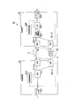
- FIG. 1 is a diagram showing a configuration of a transmission system 1 according to an embodiment of the present invention.
- the transmission system 1 shown in the figure performs 1: 1 instantaneous interruption switching.
- the transmission system 1 is, for example, an optical transmission system.
- the transmission system 1 includes a transmission device 2 on the transmission side and a transmission device 3 on the reception side. Similar to the transmission system 90 shown in FIG. 7, the transmission device 2 and the transmission device 3 are connected by the active system path P1 and the backup system path P2 in the network 5.
- the spare system path P2 is a communication path longer than the active system path P1. For example, the spare system path P2 passes through one or more switches 4.
- the backup path P2 does not have to go through the switch 4.
- the transmission device 2 includes a client unit 21, a bridge unit 22, a transponder unit 23-1, a transponder unit 23-2, a monitoring control unit 24, and a detection unit 25.
- client unit 21, the transponder unit 23-1 and the transponder unit 23-2, the client unit 911, the transponder unit 913-1 and the transponder unit 913-2 of the transmission device 91 shown in FIG. 7 can be used.
- the client unit 21 has one or more client ports.
- the client port of the client unit 21 receives the main signal transmitted from the client device.
- the client unit 21 outputs the main signal received by the client port to the bridge unit (BRG) 22.
- the bridge unit 22 outputs the main signal received from the client unit 21 to the transponder unit 23-1.
- the bridge unit 22 copies the main signal received from the client unit 21 and outputs one main signal to the transponder unit 23-1 and the other main signal to the transponder unit 23-2. Which process the bridge unit 22 performs is according to the instruction of the monitoring control unit 24.
- the transponder section 23-1 and the transponder section 23-2 are transponders on the line side.
- the transponder unit 23-1 and the transponder unit 23-2 communicate with each other when power is supplied.
- the transponder unit 23-1 converts the electric signal received from the bridge unit 22 into an optical signal, and outputs the converted optical signal to the active system path P1.
- the transponder unit 23-2 converts the electric signal input from the bridge unit 22 into an optical signal, and outputs the converted optical signal to the backup path P2. No power is supplied to the transponder unit 23-2 during normal operation in which no failure of the working system has occurred and no sign of failure has been detected.
- the monitoring control unit 24 controls each unit in the transmission device 2.
- the monitoring control unit 24 instructs the bridge unit 22 to output the main signal to the transponder unit 23-1 during normal operation.
- the monitoring and control unit 24 starts supplying power to the transponder unit 23-2 when a failure sign of the active system is detected during normal operation, and further controls to check the normality of the standby system. To do.
- the monitoring control unit 24 further instructs the bridge unit 22 to output the main signal to the transponder unit 23-1 and the transponder unit 23-2.
- the monitoring control unit 24 monitors each unit in the transmission device 2, the active system path P1 and the backup system path P2.
- the monitoring control unit 24 outputs the monitoring result to the detection unit 25.
- the detection unit 25 collects failure sign source information, and detects a failure sign in the active system path P1 based on the collected failure sign source information. When the detection unit 25 detects a failure sign, the detection unit 25 outputs the failure sign information to the monitoring control unit 24.
- the failure sign information is information that is output when a failure sign is detected in or between the devices or devices constituting the path of the active system path P1 or between these devices.
- the device that constitutes the path of the active path P1 is, for example, a DSP (digital signal processor) for optical communication.
- the failure sign source information is information for generating the failure sign information.
- the failure sign source information may include the monitoring result received from the monitoring control unit 24, or may include the state and message of the device received from the device constituting the route of the active system path P1.
- the failure sign source information is, for example, physical state data of a signal acquired from a DSP for optical communication. Further, the failure sign source information may be a warning generated in the device constituting the path of the active system path
- the transmission device 3 includes a transponder unit 31-1, a transponder unit 31-2, a delay adjustment unit 32, a selector unit (SEL) 33, a client unit 34, a monitoring control unit 35, and a detection unit 36. ..
- the transponder section 31-1, the transponder section 31-2, the delay adjusting section 32, the selector section 33, and the client section 34 are the transponder section 921-1, the transponder section 921-2, and the delay adjusting section 922 of the transmission device 92 shown in FIG.
- the selector unit 923 and the client unit 924 can be used.
- the transponder section 31-1 and the transponder section 31-2 are line-side transponders.
- the transponder unit 31-1 and the transponder unit 31-2 communicate with each other when power is supplied.
- the transponder unit 31-1 receives the optical signal transmitted through the active system path P1 and converts the received optical signal into an electric signal.
- the transponder unit 31-1 outputs the converted electric signal to the delay adjusting unit 32.
- the transponder unit 31-2 receives the optical signal transmitted through the backup path P2 and converts the received optical signal into an electric signal.
- the transponder unit 31-2 outputs the converted electric signal to the delay adjusting unit 32. During normal operation, power is not supplied to the transponder unit 31-2.
- the delay adjustment unit 32 receives the main signal transmitted through the active system path P1 from the transponder unit 31-1 during normal operation.
- the delay adjusting unit 32 outputs to the selector unit 33 without delaying the main signal received in the normal operation according to the instruction of the monitoring control unit 35.
- the delay adjustment unit 32 receives the main signal transmitted through the active system path P1 from the transponder unit 31-1 and receives the main signal transmitted through the backup system path P2 by the transponder unit. Receive from 31-2.
- the delay adjusting unit 32 delays the main signal transmitted through the active system path P1 and then outputs the delay to the selector unit 33 according to the instruction of the monitoring control unit 35, and gives a delay to the main signal transmitted through the backup system path P2. It is output to the selector unit 33 without output.
- the selector unit 33 receives the main signal transmitted from the delay adjustment unit 32 and outputs the received main signal to the client unit 34 in accordance with the instruction of the monitoring control unit 35.
- the selector unit 33 receives the main signal transmitted from the active system path P1 and the main signal transmitted from the backup system path P2 from the delay adjusting unit 32.
- the selector unit 33 selects either the main signal transmitted by the active system path P1 or the main signal transmitted by the backup system path P2 according to the instruction of the monitoring control unit 35, and outputs the main signal to the client unit 34.
- the client unit 34 has one or more client ports.
- the client unit 34 outputs the main signal received from the selector unit 33 from the client port.
- the monitoring control unit 35 controls each unit in the transmission device 3. During normal operation, the monitoring control unit 35 instructs the delay adjusting unit 32 to output the main signal transmitted through the active system path P1 to the selector unit 33 without adding a delay. Further, the monitoring control unit 35 instructs the selector unit 33 to output the main signal transmitted through the active system path P1 to the client unit 34 during normal operation.
- the monitoring control unit 35 starts supplying power to the transponder unit 31-2 and checks the normality of the standby system.
- the monitoring control unit 35 delays the main signal transmitted through the active system path P1 and sets the delay difference from the main signal transmitted with the standby system path P2 to 0.
- the delay adjusting unit 32 is instructed to do so.
- the monitoring control unit 35 instructs the selector unit 33 to output the main signal output by the transponder unit 31-2 to the client unit 34. To do. Further, the monitoring control unit 35 monitors each unit in the transmission device 3, the active system path P1 and the backup system path P2. The monitoring control unit 35 outputs the monitoring result to the detection unit 36.
- the detection unit 36 collects failure sign source information, and detects a failure sign in the active system path P1 based on the collected failure sign source information. When the detection unit 36 detects a failure sign, the detection unit 36 outputs the failure sign information to the monitoring control unit 35.
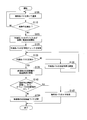
- FIG. 2 is a flow chart showing the operation of the transmission system 1.
- the transmission system 1 communicates using the active system path P1 during normal operation (step S105). Specifically, the bridge unit 22 of the transmission device 2 outputs the main signal received from the client unit 21 to the transponder unit 23-1 in accordance with the instruction of the monitoring control unit 24.
- the transponder unit 23-1 outputs the main signal converted into an optical signal to the active system path P1.
- the transponder unit 31-1 of the transmission device 3 receives the main signal transmitted through the active system path P1.
- the transponder unit 31-1 converts the received main signal into an electric signal and outputs it to the delay adjusting unit 32.
- the delay adjusting unit 32 outputs to the selector unit 33 without adding a delay to the main signal according to the instruction of the monitoring control unit 35.
- the selector unit 33 outputs the main signal to the client unit 34 according to the instruction of the monitoring control unit 35.
- the client unit 34 outputs the main signal to the outside of the device.
- step S110: NO the transmission system 1 performs the process of step S105.
- the transmission system 1 performs the processes after step S115. For example, when failure sign information such as deterioration of optical power in the active system path P1 is detected, the transmission system 1 starts supplying power to the device or device of the standby system path P2 and starts a normality check. At the stage when a failure sign is detected, it is assumed that the main signal can be communicated by the active system path P1.
- the transmission system 1 performs the processes of steps S115 to S130 in each of the transmission device 2 and the transmission device 3. First, the processing of the transmission device 2 in steps S115 to S130 will be described.
- the monitoring control unit 24 of the transmission device 2 acquires failure sign information from the detection unit 25.
- the monitoring control unit 24 receives the failure sign information from the transmission device 3. In this case, even if the monitoring control unit 24 acquires the failure sign information set by the detection unit 36 of the transmission device 3 from the overhead (OH) of the optical signal received from the transmission device 3 using the active system path P1. Good.
- the monitoring control unit 24 may receive the failure sign information output by the detection unit 36 of the transmission device 3 via the control network or the like.
- the detection unit 25 collects failure sign source information directly from each device in the transmission device 2, each function unit, or the like, or via the monitoring control unit 24.
- the detection unit 25 may acquire the failure sign source information acquired by the transmission device 3 from the overhead of the optical signal output from the transmission device 3 and transmitted the active system path P1. Further, the detection unit 25 may receive the failure sign source information transmitted from the transmission device 3 by the control network or the like.
- the detection unit 25 may set the acquired failure sign source information as the overhead of the main signal transmitted by the active system path P1 and transmit it to the transmission device 3, and the detection unit 25 may transmit the acquired failure sign source information to the transmission device 3 via a control network (not shown).
- the detection unit 36 may be notified.
- the failure sign information To generate When the detection unit 25 determines that a failure sign has been detected in or between the devices or devices constituting the path of the active system path P1 based on the acquired failure sign source information, the failure sign information To generate.
- the detection unit 25 outputs the generated failure sign information to the monitoring control unit 24.
- the detection unit 25 may set the generated failure sign information as the overhead of the main signal transmitted by the active system path P1 and notify the transmission device 3, and transmit the generated failure sign information to the transmission device 3 via the control network. May be good.
- the monitoring control unit 24 of the transmission device 2 acquires the failure sign information
- the monitoring control unit 24 starts supplying power to the standby devices and devices including the transponder unit 23-2 when the power is not supplied (the power supply to them is started ().
- Step S115) The monitoring control unit 24 further starts checking whether the bridge unit 22 and the transponder unit 23-2 belonging to the backup system path P2 operate normally by supplying power (step S120). For example, after instructing the bridge unit 22 to copy the data, the monitoring control unit 24 confirms whether the same data as the data transmitted by the bridge unit 22 to the active system path P1 is transmitted to the backup system path P2 side.
- the monitoring control unit 24 controls the transponder unit 23-2 to execute a connection confirmation such as a loopback test and a delay measurement with the transponder unit 31-2 of the transmission device 3.
- the monitoring control unit 24 confirms the normality of the backup path P2.
- the connection may be confirmed by using, for example, the overhead of the OTN of the optical signal. Even if the monitoring control unit 24 sets the result of the normality check as the overhead of the main signal transmitted by the active system path P1, or notifies the monitoring control unit 35 of the transmission device 3 via the control network. Good.
- the monitoring control unit 35 of the transmission device 3 acquires failure sign information from the detection unit 36.
- the monitoring control unit 35 may receive failure sign information from the transmission device 2. In this case, even if the monitoring control unit 35 acquires the failure sign information output by the detection unit 25 of the transmission device 2 from the overhead (OH) of the optical signal received from the transmission device 2 using the active system path P1. Good. Further, the monitoring control unit 35 may receive the failure sign information output by the detection unit 25 of the transmission device 2 via the control network or the like.
- the detection unit 36 collects failure sign source information from each device, each function unit, and the like in the transmission device 3 in the same manner as the detection unit 25 of the transmission device 2.
- the detection unit 36 may set the acquired failure sign source information as the overhead of the main signal transmitted by the active system path P1 and transmit it to the transmission device 2, and the detection unit 36 may transmit the acquired failure sign source information to the transmission device 2 via a control network (not shown).
- the detection unit 25 may be notified.
- the detection unit 36 may acquire the failure sign source information acquired by the transmission device 2 from the overhead of the optical signal output from the transmission device 2 and transmitted the active system path P1. Further, the detection unit 36 may receive the failure sign source information transmitted from the transmission device 2 by the control network or the like.
- the failure sign information To generate When the detection unit 36 determines that a failure sign has been detected in or between the devices or devices constituting the path of the active system path P1 based on the acquired failure sign source information, the failure sign information To generate.
- the detection unit 36 outputs the generated failure sign information to the monitoring control unit 35.
- the detection unit 36 may set the generated failure sign information as the overhead of the main signal transmitted by the active system path P1 and notify the transmission device 2, and transmit the generated failure sign information to the transmission device 2 via the control network. May be good.
- the monitoring control unit 35 of the transmission device 3 acquires the failure sign information
- the monitoring control unit 35 starts supplying power to the standby devices and devices including the transponder unit 31-2 when the power is not supplied (the power supply to them is started ().
- Step S115) The monitoring control unit 35 further starts checking whether the transponder unit 31-2, the delay adjusting unit 32, and the selector unit 33 belonging to the backup system path P2 operate normally (step S120). For example, the monitoring control unit 35 confirms whether or not the transponder unit 31-2, the delay adjusting unit 32, and the selector unit 33 are normally activated by supplying power.
- the monitoring control unit 35 controls the transponder unit 31-2 to execute a connection confirmation such as a loopback test and a delay measurement with the transponder unit 23-2 of the transmission device 2.
- a connection confirmation such as a loopback test and a delay measurement with the transponder unit 23-2 of the transmission device 2.
- the monitoring control unit 35 confirms the normality of the backup path P2.
- the connection may be confirmed by using, for example, the overhead of the OTN of the optical signal. Even if the monitoring control unit 35 sets the result of the normality check as the overhead of the main signal transmitted by the active system path P1, or notifies the monitoring control unit 24 of the transmission device 2 via the control network. Good.
- the monitoring control unit 24 of the transmission device 2 and the monitoring control unit 35 of the transmission device 3 determine whether or not the backup path P2 is normal (step S125). When at least one of the monitoring control unit 24 of the transmission device 2 and the monitoring control unit 35 of the transmission device 3 determines that the backup system path P2 is not normal (step S125: NO), the transmission system 1 sets the backup system path. The recovery work of P2 is carried out (step S130), and the process from step S125 is repeated.
- step S120 When the result of the normality check is notified between the transmission device 2 and the transmission device 3, the process up to step S120 is completed in the transmission device 3 even if the process up to step S120 has already been completed in the transmission device 2. If not, it is determined as NO in step S125. Similarly, even if the processing up to step S120 is completed in the transmission device 3, if the processing up to step S120 is not completed in the transmission device 2, NO is determined in step S125.
- step S135. the monitoring control unit 35 instructs the delay adjustment unit 32 to start the delay adjustment in order to buffer the main signal transmitted through the active system path P1.
- the delay adjustment unit 32 receives this instruction from the monitoring control unit 35, the delay adjustment unit 32 starts the delay adjustment.
- the delay adjustment is performed by, for example, controlling the amount of data stored in the FIFO (First In First Out) memory. This is because the signal that transmits the active system path P1 arrives earlier than the signal that transmits the backup system path P2.
- the monitoring control unit 35 confirms that the delay difference between the main signals generated by the path difference between the active system path P1 and the backup system path P2 becomes zero (step S135).
- the monitoring control unit 35 of the transmission device 3 sets the delay difference between the active system path P1 and the backup system path P2 to zero, and then completes the adjustment of the delay difference. Notify the monitoring control unit 24 of the transmission device 2. For example, the monitoring control unit 35 sets the completion of the delay difference adjustment to the overhead of the main signal transmitted by the active system path P1, or notifies the monitoring control unit 24 of the transmission device 2 via the control network. .. Upon receiving the notification of the completion of adjustment, the monitoring control unit 24 of the transmission device 2 instructs the bridge unit 22 to copy the data if it has not copied the data. Upon receiving this instruction, the bridge unit 22 copies the main signal received from the client unit 21.
- the main signal for transmitting the active path P1 is used as the active main signal
- the copy main signal for transmitting the spare path P2 is used as the spare main signal.
- the bridge unit 22 transmits the active system main signal to the transponder unit 23-1 corresponding to the active system path P1 and transmits the spare system main signal to the transponder unit 23-2 corresponding to the spare system path P2.
- the transponder unit 23-1 outputs the active system main signal converted into an optical signal to the active system path P1.
- the transponder unit 23-2 outputs the spare system main signal converted into an optical signal to the spare system path P2.
- the transponder unit 31-1 of the transmission device 3 receives the active system main signal that has transmitted the active system path P1.
- the transponder unit 31-1 converts the received active system main signal from an optical signal to an electric signal, and then outputs the signal to the delay adjusting unit 32.
- the transponder unit 31-2 receives the backup system main signal that has received the backup system path P2.
- the transponder unit 31-2 converts the received standby system main signal from an optical signal to an electric signal, and then outputs the signal to the delay adjusting unit 32.
- the delay adjusting unit 32 informs the selector unit 33 of the active system main signal and the standby system main signal. Is output.
- the selector unit 33 selects the active system main signal and outputs the selected active system main signal to the client unit 34.
- step S140 When the monitoring control unit 35 of the transmission device 3 determines that both the condition (1) and the condition (2) are satisfied (step S140: YES), transmission to and from the transmission device 2 while using the active system path P1. Is controlled so as to continue (step S145).
- the condition (1) is a condition that the failure sign information is recovered within a predetermined time
- the condition (2) is a condition that the operator who has confirmed the failure sign information does not input a switching instruction.
- the transmission system 1 continues the processing after the delay adjustment in step S135 is performed.
- the transmission system 1 may perform the process of step S105.
- the monitoring control unit 35 determines that one or both of the condition (1) and the condition (2) are not satisfied (step S140: NO)
- the monitoring control unit 35 switches from the active system path to the backup system path (step S150). ). That is, the monitoring control unit 35 instructs the selector unit 33 to output the backup system main signal to the client unit 34.
- the selector unit 33 receives the instruction from the monitoring control unit 35
- the selector unit 33 outputs the standby system main signal to the client unit 34.
- the monitoring control unit 35 may switch from the active system path to the backup system path when a failure of the active system path P1 is detected.
- the monitoring control unit 35 sets the fact that the path has been switched to the overhead of the main signal transmitted by the active system path P1 or the backup system path P2, or the monitoring control unit of the transmission device 2 via the control network. 24 may be notified. As described above, after the delay difference between the active system main signal and the spare system main signal is set to zero, the path of the active system and the spare system is switched by the selector unit 33 to realize non-interruptive switching. The monitoring control unit 35 also switches from the active system path to the backup system path when it detects the occurrence of a failure of the device or device constituting the active system path P1 or receives the notification of the failure occurrence.
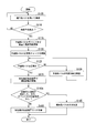
- FIG. 3 is a flow chart showing other operations of the transmission system 1.
- the transmission system 1 may perform the operation shown in the flow chart of FIG. 3 instead of the operation shown in the flow chart of FIG.
- the same processes as those of the flow chart of FIG. 2 are designated by the same reference numerals, and the description thereof will be omitted.
- the difference between the process shown in the flow chart of FIG. 3 and the process shown in the flow chart of FIG. 2 is that the process of step S140a is performed instead of the process of step S140. That is, when it is determined that one or both of the condition (1) and the condition (2) are satisfied (step S140a: YES), the monitoring control unit 35 of the transmission device 3 performs the process of step S145.
- condition (1) is a condition that the failure sign information is recovered within a predetermined time
- condition (2) is a switching instruction from the operator who confirmed the failure sign information. It is a condition that there is no input of.
- step S140a: NO when it is determined that both the condition (1) and the condition (2) are not satisfied, the monitoring control unit 35 performs the process of step S150.
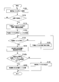
- FIG. 4 is a flow chart showing other operations of the transmission system 1.
- the transmission system 1 may perform the operation shown in the flow chart of FIG. 4 instead of the operation shown in the flow chart of FIG. 2 or 3.
- the same processing as that of the flow chart of FIG. 2 is designated by the same reference numerals, and the description thereof will be omitted.
- the difference between the process shown in the flow chart of FIG. 4 and the process shown in the flow chart of FIG. 2 is that the process of step S140b is performed instead of the process of step S140. That is, when it is determined that one or both of the condition (3) and the condition (4) are satisfied (step S140b: YES), the monitoring control unit 35 of the transmission device 3 performs the process of step S150.
- the condition (3) is a condition that the failure sign information has not recovered even after a lapse of a predetermined time
- the condition (4) is a condition that a switching instruction is input from the operator who confirmed the failure sign information. ..
- FIG. 5 is a flow chart showing other operations of the transmission system 1.
- the transmission system 1 may perform the operation shown in the flow chart of FIG. 5 instead of the operation shown in the flow charts of FIGS. 2 to 4.
- the same processes as those of the flow chart of FIG. 4 are designated by the same reference numerals, and the description thereof will be omitted.
- the difference between the process shown in the flow chart of FIG. 5 and the process shown in the flow chart of FIG. 4 is that the process of step S140c is performed instead of the process of step S140b. That is, when it is determined that both the condition (3) and the condition (4) are satisfied (step S140c: YES), the monitoring control unit 35 of the transmission device 3 performs the process of step S150.
- condition (3) is a condition that the failure sign information has not recovered even after a lapse of a predetermined time
- condition (4) is an operator who has confirmed the failure sign information. It is a condition that the switching instruction from is input.
- the transmission device includes a detection unit that detects a sign of failure.
- the transmission device does not supply power to devices and devices used only for the spare system path, such as the spare system transponder.
- the detection unit outputs failure sign information of the active system path
- the transmission device uses it as a trigger to supply power to the devices and devices belonging to the standby system path, and starts checking the normality of the backup system path. In this way, the transmission device switches the path by performing a normality check using the failure sign information as a trigger while significantly reducing the power supply by not operating the transponder or the like of the backup system path during normal operation. be able to.
- ITU-T G.I. Switching may be performed to allow bit loss within 50 ms (milliseconds) specified in the 841 recommendation.
- the monitoring control unit 35 instructs the delay adjusting unit 32 so that the delay difference between the main signal transmitted through the active system path P1 and the main signal transmitted through the backup system path P2 is within 50 ms.
- the delay adjusting unit 32 delays the main signal transmitted through the active system path P1 so that the delay difference from the main signal transmitted through the standby system path P2 is within 50 ms (milliseconds).
- the failure sign information may be information obtained by analyzing the failure sign source information collected from one or more devices by an information analysis method such as machine learning or deep learning. Further, the failure sign information may be information processed based on the operator's network operation policy. Further, the failure sign information may be information that combines them.
- the detection unit 25 of the transmission device 2 may generate failure sign information based on the failure sign source information in the own device, and receives the failure sign source information in the own device via the control network or the like. Failure sign information may be generated based on the failure sign source information.
- the detection unit 36 of the transmission device 3 may generate failure sign information based on the failure sign source information in the own device, and may generate the failure sign source information in the own device via the control network or the like. Failure sign information may be generated based on the received failure sign source information. Further, the detection unit 25 of the transmission device 2 and the detection unit 36 of the transmission device 3 receive the failure sign information of the other device via the control network or the overhead of the main signal, and use it as information for generating the failure sign information. You may.
- the transmission device 2 and the transmission device 3 may check the operation of the switch 4 on the network 5 as a normality check of the functional unit belonging to the backup system path. For example, it may be confirmed that power can be supplied to the switch 4 and that the switch 4 can be set to a desired route.
- the result of the normality check on the network 5 may be transmitted and received between the transmission device 2 and the transmission device 3 with the overhead of the main signal, or may be transmitted and received via the control network.
- FIG. 6 is a device configuration diagram showing a hardware configuration example of the transmission device 2 and the transmission device 3.
- the transmission device 2 and the transmission device 3 include a processor 51, a storage unit 52, a communication interface 53, and a user interface 54.
- the processor 51 is a central processing unit that performs calculations and controls.
- the processor 51 is, for example, a CPU.
- the processor 51 reads a program from the storage unit 52 and executes it.
- the storage unit 52 further has a work area for the processor 51 to execute various programs and the like.
- the communication interface 53 connects to other devices so as to be able to communicate with each other.
- the user interface 54 is an input device such as a button, a keyboard, or a pointing device, or a display device such as a lamp or a display. An artificial operation is input by the user interface 54.
- the functions of the monitoring control unit 24 and the detection unit 25 of the transmission device 2 are realized by the processor 51 reading a program from the storage unit 52 and executing it. All or part of these functions may be realized by using hardware such as ASIC (Application Specific Integrated Circuit), PLD (Programmable Logic Device), and FPGA (Field Programmable Gate Array).
- the client unit 21, the bridge unit 22, the transponder unit 23-1, and the transponder unit 23-2 of the transmission device 2 are realized by the communication interface 53. Some of these functions may be realized by the processor 51 reading a program from the storage unit 52 and executing the program.
- the functions of the monitoring control unit 35 and the detection unit 36 of the transmission device 3 are realized by the processor 51 reading the program from the storage unit 52 and executing it. In addition, all or a part of these functions may be realized by using hardware such as ASIC, PLD and FPGA.
- the transponder unit 31-1, the transponder unit 31-2, the delay adjusting unit 32, the selector unit 33, and the client unit 34 of the transmission device 3 are realized by the communication interface 53. Some of these functions may be realized by the processor 51 reading a program from the storage unit 52 and executing the program.
- the transmission device includes a first communication unit, a second communication unit, a detection unit, a control unit, and a selection unit.
- the first communication unit communicates using the first path when power is supplied.
- the first communication unit is the transponder unit 31-1 and the first path is the active system path P1.
- the second communication unit communicates using the second path when power is supplied.
- the second communication unit is the transponder unit 31-2, and the second path is the backup system path P2.
- the detection unit detects a failure sign.
- the control unit does not supply power to the second communication unit when the detection unit has not detected a failure sign.
- the control unit When the detection unit detects a sign of failure, the control unit starts supplying power to the second communication unit and confirms the normality of the second path before switching from the first path to the second path. ..
- the control unit is, for example, a monitoring control unit 35.
- the selection unit selects and outputs either the signal received by the first communication unit or the signal received by the second communication unit.
- the selection unit is, for example, the selector unit 33.
- the control unit switches from the first path to the second path when the path switching trigger occurs after the normality is confirmed by the normality confirmation.
- the trigger for path switching is, for example, continuation of detection of a failure sign for a predetermined time or longer, or input of a switching instruction by the operator.
- the selection unit selects and outputs the signal received by the first communication unit before switching to the second path, and selects and outputs the signal received by the second communication unit after switching to the second path. To do.
- the transmission device may further have a delay adjusting unit.
- the delay adjusting unit adjusts the delay difference between the signal received by the first communication unit and the signal received by the second communication unit to a predetermined value or less, and outputs the signal with the adjusted delay difference to the selection unit.
Landscapes
- Engineering & Computer Science (AREA)
- Computer Networks & Wireless Communication (AREA)
- Signal Processing (AREA)
- Physics & Mathematics (AREA)
- Electromagnetism (AREA)
- Computer Security & Cryptography (AREA)
- Maintenance And Management Of Digital Transmission (AREA)
- Data Exchanges In Wide-Area Networks (AREA)
Abstract
Description
同様に、伝送装置3の検出部36は自装置内の故障予兆元情報を基にして、故障予兆情報を生成してもよく、自装置内の故障予兆元情報と、制御ネットワーク等を介して受信した故障予兆元情報とを基にして、故障予兆情報を生成してもよい。また、伝送装置2の検出部25及び伝送装置3の検出部36は、他装置の故障予兆情報を制御ネットワークや主信号のオーバーヘッドを介して受信し、故障予兆情報を生成するための情報として利用してもよい。
Claims (6)
- 電源が供給された場合に、第一パスを用いて通信する第一通信部と、
電源が供給された場合に、第二パスを用いて通信する第二通信部と、
故障予兆を検出する検出部と、
前記検出部が故障予兆を未検出の場合は前記第二通信部への電源供給を行わず、前記検出部が故障予兆を検出した場合は前記第一パスから前記第二パスへの切替の前に、前記第二通信部への電源供給の開始と前記第二パスの正常性確認とを行う制御部と、
前記第一通信部及び前記第二通信部が信号を受信した場合に、前記第一通信部が受信した前記信号と前記第二通信部が受信した前記信号とのいずれかを選択して出力する選択部と、
を備える伝送装置。 - 前記制御部は、前記正常性確認により正常性が確認された後にパス切替のトリガが発生した場合に、前記第一パスから前記第二パスへの切替を行い、
前記選択部は、前記第二パスへの切替前は、前記第一通信部が受信した前記信号を選択して出力し、前記第二パスへの切替後は、前記第二通信部が受信した前記信号を選択して出力する、
請求項1に記載の伝送装置。 - 前記第一通信部が受信した信号と、前記第二通信部が受信した信号との遅延差を所定以下に調整し、遅延差が調整された前記信号を前記選択部に出力する遅延調整部をさらに備える、
請求項1又は請求項2に記載の伝送装置。 - 電源が供給された場合に、第一パスを用いて通信する第一通信部と、電源が供給された場合に、第二パスを用いて通信する第二通信部とを有する伝送装置における伝送方法であって、
前記第一通信部が前記第一パスを用いて通信する通信ステップと、
故障予兆を検出する検出ステップと、
故障予兆が未検出の場合は前記第二通信部への電源供給を行わず、故障予兆が検出された場合は前記第一パスから前記第二パスへの切替の前に前記第二通信部への電源供給の開始と前記第二パスの正常性確認とを行う制御ステップと、
前記第一通信部及び前記第二通信部が信号を受信した場合に、前記第一通信部が受信した前記信号と前記第二通信部が受信した前記信号とのいずれかを選択して出力する選択ステップと、
を有する伝送方法。 - 前記正常性確認により正常性が確認された後にパス切替のトリガが発生した場合に、前記第一パスから前記第二パスへの切替を行う切替ステップをさらに有し、
前記選択ステップにおいては、前記第二パスへの切替前は、前記第一通信部が受信した前記信号を選択して出力し、前記第二パスへの切替後は、前記第二通信部が受信した前記信号を選択して出力する、
請求項4に記載の伝送方法。 - 前記第一通信部が受信した信号と、前記第二通信部が受信した信号との遅延差を所定以下に調整する遅延調整ステップをさらに有する、
請求項4又は請求項5に記載の伝送方法。
Priority Applications (3)
| Application Number | Priority Date | Filing Date | Title |
|---|---|---|---|
| JP2021553946A JP7288214B2 (ja) | 2019-10-30 | 2019-10-30 | 伝送装置及び伝送方法 |
| US17/766,451 US11984925B2 (en) | 2019-10-30 | 2019-10-30 | Transmission apparatus and transmission method |
| PCT/JP2019/042486 WO2021084635A1 (ja) | 2019-10-30 | 2019-10-30 | 伝送装置及び伝送方法 |
Applications Claiming Priority (1)
| Application Number | Priority Date | Filing Date | Title |
|---|---|---|---|
| PCT/JP2019/042486 WO2021084635A1 (ja) | 2019-10-30 | 2019-10-30 | 伝送装置及び伝送方法 |
Publications (1)
| Publication Number | Publication Date |
|---|---|
| WO2021084635A1 true WO2021084635A1 (ja) | 2021-05-06 |
Family
ID=75714922
Family Applications (1)
| Application Number | Title | Priority Date | Filing Date |
|---|---|---|---|
| PCT/JP2019/042486 Ceased WO2021084635A1 (ja) | 2019-10-30 | 2019-10-30 | 伝送装置及び伝送方法 |
Country Status (3)
| Country | Link |
|---|---|
| US (1) | US11984925B2 (ja) |
| JP (1) | JP7288214B2 (ja) |
| WO (1) | WO2021084635A1 (ja) |
Cited By (1)
| Publication number | Priority date | Publication date | Assignee | Title |
|---|---|---|---|---|
| JPWO2024100699A1 (ja) * | 2022-11-07 | 2024-05-16 |
Citations (6)
| Publication number | Priority date | Publication date | Assignee | Title |
|---|---|---|---|---|
| JPH0795132A (ja) * | 1993-09-20 | 1995-04-07 | Fujitsu Ltd | 冗長系伝送路運用方式 |
| JP2009100442A (ja) * | 2007-09-27 | 2009-05-07 | Hitachi Communication Technologies Ltd | ネットワークシステム |
| JP2013005210A (ja) * | 2011-06-16 | 2013-01-07 | Fujitsu Telecom Networks Ltd | パケット伝送システムおよびパケット伝送装置並びに無瞬断切替方法 |
| JP2013243559A (ja) * | 2012-05-21 | 2013-12-05 | Mitsubishi Electric Corp | 光伝送ノードおよび経路切替方法 |
| WO2014050022A1 (ja) * | 2012-09-25 | 2014-04-03 | 日本電気株式会社 | 通信システムおよび通信方法 |
| WO2017170006A1 (ja) * | 2016-03-30 | 2017-10-05 | 日本電気株式会社 | 通信システム、管理装置、通信方法およびプログラム |
Family Cites Families (4)
| Publication number | Priority date | Publication date | Assignee | Title |
|---|---|---|---|---|
| JP4909675B2 (ja) | 2006-08-17 | 2012-04-04 | エヌ・ティ・ティ・コミュニケーションズ株式会社 | 伝送装置、伝送方法、及びプログラム |
| EP2043308B1 (en) * | 2007-09-27 | 2012-01-25 | Hitachi, Ltd. | GMPLS in optical networks |
| US9013977B2 (en) * | 2011-06-08 | 2015-04-21 | Fujitsu Limited | Method and system for reducing traffic disturbance in a communication network caused by intermittent failure |
| US9002195B2 (en) * | 2011-09-29 | 2015-04-07 | Nec Laboratories America, Inc. | Solution for hitless protection in high-speed OTN framer and front-end |
-
2019
- 2019-10-30 JP JP2021553946A patent/JP7288214B2/ja active Active
- 2019-10-30 US US17/766,451 patent/US11984925B2/en active Active
- 2019-10-30 WO PCT/JP2019/042486 patent/WO2021084635A1/ja not_active Ceased
Patent Citations (6)
| Publication number | Priority date | Publication date | Assignee | Title |
|---|---|---|---|---|
| JPH0795132A (ja) * | 1993-09-20 | 1995-04-07 | Fujitsu Ltd | 冗長系伝送路運用方式 |
| JP2009100442A (ja) * | 2007-09-27 | 2009-05-07 | Hitachi Communication Technologies Ltd | ネットワークシステム |
| JP2013005210A (ja) * | 2011-06-16 | 2013-01-07 | Fujitsu Telecom Networks Ltd | パケット伝送システムおよびパケット伝送装置並びに無瞬断切替方法 |
| JP2013243559A (ja) * | 2012-05-21 | 2013-12-05 | Mitsubishi Electric Corp | 光伝送ノードおよび経路切替方法 |
| WO2014050022A1 (ja) * | 2012-09-25 | 2014-04-03 | 日本電気株式会社 | 通信システムおよび通信方法 |
| WO2017170006A1 (ja) * | 2016-03-30 | 2017-10-05 | 日本電気株式会社 | 通信システム、管理装置、通信方法およびプログラム |
Non-Patent Citations (2)
| Title |
|---|
| KITAMURA, KEI ET AL.: "Large capacity ODU path protection without bit disruption for low latency core/metro network", IEICE TECHNICAL REPORT, vol. 118, no. 505, 15 March 2019 (2019-03-15), pages 73 - 76 * |
| METAARC: "FUJITSU Network Virtuora/FUJITSU Network INFINITY Thinking network that supports MetaArc to lead digital innovation in business", FUJITSU FORUM, May 2017 (2017-05-01) * |
Cited By (3)
| Publication number | Priority date | Publication date | Assignee | Title |
|---|---|---|---|---|
| JPWO2024100699A1 (ja) * | 2022-11-07 | 2024-05-16 | ||
| WO2024100699A1 (ja) * | 2022-11-07 | 2024-05-16 | 日立Astemo株式会社 | 通信装置、通信システム及び故障予兆診断方法 |
| JP7748578B2 (ja) | 2022-11-07 | 2025-10-02 | Astemo株式会社 | 通信装置、通信システム及び故障予兆診断方法 |
Also Published As
| Publication number | Publication date |
|---|---|
| US20240056179A1 (en) | 2024-02-15 |
| JP7288214B2 (ja) | 2023-06-07 |
| JPWO2021084635A1 (ja) | 2021-05-06 |
| US11984925B2 (en) | 2024-05-14 |
Similar Documents
| Publication | Publication Date | Title |
|---|---|---|
| JP6607057B2 (ja) | 伝送装置、伝送システム、及び伝送方法 | |
| JP2009010441A (ja) | インタフェース切替方法および装置 | |
| CN101317388A (zh) | 多协议标签切换的标签切换路径保护切换的装置和方法 | |
| JP7288214B2 (ja) | 伝送装置及び伝送方法 | |
| US20030079004A1 (en) | Load balancer for network processor | |
| JP4841474B2 (ja) | 光伝送装置 | |
| US7738363B2 (en) | Network relay apparatus | |
| JP4024607B2 (ja) | 光クロスコネクト装置 | |
| JP4855878B2 (ja) | マルチリング・ネットワーク・システム | |
| JP5730737B2 (ja) | マルチリング網におけるパス設定方法及びパス切替方法 | |
| US20080298800A1 (en) | Transmission device and route verifying method | |
| JP6056494B2 (ja) | 判定装置、判定方法、及び、判定プログラム | |
| EP4002775B1 (en) | Transmission device and transmission method | |
| JPH114206A (ja) | 端局装置 | |
| GB2353173A (en) | Telecommunications system | |
| JP2000209152A (ja) | 波長分割多重伝送ネットワ―クにおける光波パス端障害検出/切替による障害回復方法及び伝送装置 | |
| JP2006041921A (ja) | 無瞬断切替装置 | |
| JP2001326620A (ja) | スタンバイパスアクセス方法および装置 | |
| JP5292892B2 (ja) | 回線収容装置および制御方法 | |
| JP2006222632A (ja) | 光クロスコネクト装置と伝送装置の連係方式 | |
| CN113285779B (zh) | 一种通信设备及时钟同步的方法 | |
| WO2020100700A1 (ja) | 伝送装置、伝送システム及び遅延調整方法 | |
| JP2606130B2 (ja) | ループ型ネットワーク | |
| JPH01202951A (ja) | 光通信システム | |
| CA2296660A1 (en) | Communication node, wdm network, and network communication method |
Legal Events
| Date | Code | Title | Description |
|---|---|---|---|
| 121 | Ep: the epo has been informed by wipo that ep was designated in this application |
Ref document number: 19950945 Country of ref document: EP Kind code of ref document: A1 |
|
| ENP | Entry into the national phase |
Ref document number: 2021553946 Country of ref document: JP Kind code of ref document: A |
|
| WWE | Wipo information: entry into national phase |
Ref document number: 17766451 Country of ref document: US |
|
| NENP | Non-entry into the national phase |
Ref country code: DE |
|
| 122 | Ep: pct application non-entry in european phase |
Ref document number: 19950945 Country of ref document: EP Kind code of ref document: A1 |