WO2021084617A1 - 電動機駆動装置、冷凍サイクル装置、空気調和機、給湯機、及び冷蔵庫 - Google Patents
電動機駆動装置、冷凍サイクル装置、空気調和機、給湯機、及び冷蔵庫 Download PDFInfo
- Publication number
- WO2021084617A1 WO2021084617A1 PCT/JP2019/042376 JP2019042376W WO2021084617A1 WO 2021084617 A1 WO2021084617 A1 WO 2021084617A1 JP 2019042376 W JP2019042376 W JP 2019042376W WO 2021084617 A1 WO2021084617 A1 WO 2021084617A1
- Authority
- WO
- WIPO (PCT)
- Prior art keywords
- electric motor
- switching
- current
- connection
- inverter
- Prior art date
- Legal status (The legal status is an assumption and is not a legal conclusion. Google has not performed a legal analysis and makes no representation as to the accuracy of the status listed.)
- Ceased
Links
Images





Classifications
-
- H—ELECTRICITY
- H02—GENERATION; CONVERSION OR DISTRIBUTION OF ELECTRIC POWER
- H02P—CONTROL OR REGULATION OF ELECTRIC MOTORS, ELECTRIC GENERATORS OR DYNAMO-ELECTRIC CONVERTERS; CONTROLLING TRANSFORMERS, REACTORS OR CHOKE COILS
- H02P25/00—Arrangements or methods for the control of AC motors characterised by the kind of AC motor or by structural details
- H02P25/16—Arrangements or methods for the control of AC motors characterised by the kind of AC motor or by structural details characterised by the circuit arrangement or by the kind of wiring
- H02P25/18—Arrangements or methods for the control of AC motors characterised by the kind of AC motor or by structural details characterised by the circuit arrangement or by the kind of wiring with arrangements for switching the windings, e.g. with mechanical switches or relays
-
- H—ELECTRICITY
- H02—GENERATION; CONVERSION OR DISTRIBUTION OF ELECTRIC POWER
- H02P—CONTROL OR REGULATION OF ELECTRIC MOTORS, ELECTRIC GENERATORS OR DYNAMO-ELECTRIC CONVERTERS; CONTROLLING TRANSFORMERS, REACTORS OR CHOKE COILS
- H02P27/00—Arrangements or methods for the control of AC motors characterised by the kind of supply voltage
- H02P27/04—Arrangements or methods for the control of AC motors characterised by the kind of supply voltage using variable-frequency supply voltage, e.g. inverter or converter supply voltage
- H02P27/06—Arrangements or methods for the control of AC motors characterised by the kind of supply voltage using variable-frequency supply voltage, e.g. inverter or converter supply voltage using DC to AC converters or inverters
Definitions
- the present invention relates to an electric motor drive device, a refrigeration cycle device including the electric motor drive device, and an air conditioner, a water heater, and a refrigerator equipped with the refrigeration cycle device.
- a drive wheel a motor connected so as to transmit a driving force to the drive wheel and having a switchable winding, an input unit for instructing the output of the motor, and a control signal based on an instruction from the input unit.
- the output control unit, the inverter whose duty ratio is adjusted based on the control signal from the control unit to supply the output voltage to the motor, the winding switching unit that switches the winding, and the motor current that flows through the winding are detected.
- a saddle-type vehicle including a current detection unit and a phase detection unit that detects the phase of the motor.
- the control unit of this saddle-type vehicle has a switching determination unit that determines whether or not the winding switching condition is satisfied, and a duty ratio adjustment period when the winding switching condition is satisfied, and an instruction from the input unit.
- the adjustment unit adjusts the duty ratio of the inverter based on the motor current detected by the current detection unit and the phase of the motor detected by the phase detection unit so that the motor current becomes 0 regardless of the above. It includes a switching instruction unit that instructs the winding switching unit to switch the winding during the duty ratio adjustment period (see, for example, Patent Document 1).
- JP 2013-62888 (for example, claim 1, FIGS. 2 to 6)
- the present invention has been made in view of the above, and the switching operation of the switch for switching the connection state of the windings of the electric motor can be performed without stopping the rotational operation of the electric motor, and the connection state can be switched.
- An object of the present invention is to provide an electric motor drive device which is less likely to cause a failure due to the failure and a device provided with the electric motor drive device.
- the electric motor drive device includes a connection switching device that has a switching device and switches the connection state of the windings of the electric motor by performing the switching operation of the switching device during the rotation operation of the electric motor, and the switching device.
- An AC voltage is applied to the winding through the winding, and a countercurrent voltage is applied from the winding of the electric motor in rotation operation via the switch, and the electric motor is controlled by controlling the inverter.
- It has a control device that controls the rotation operation and causes the connection switching device to switch the connection state, and the first effective value of the alternating current flowing through the winding is before the switching operation of the switching device.
- the first stage having a current control period closer to zero than the second effective value of the AC current flowing through the winding, and the stage after the first stage, the AC voltage output by the inverter is stopped.
- a second stage having a power supply stop period is provided, and the switching operation of the switch is executed during the period of the second stage.
- a period for stopping the energization of the inverter is provided, and the connection switching device is switched within that period. Since the device is switched, the connection switching device is less likely to fail, and the life of the motor drive device can be extended.
- connection state of the winding is switched during the current control period in which the rotational operation of the electric motor is not stopped. Therefore, it is not necessary to suspend the rotational operation of the motor and then restart the motor in order to switch the connection state of the windings.
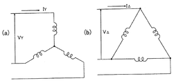
- FIG. 1 and (b) are diagrams conceptually showing windings of electric motors in different wiring states.
- FIG. It is a functional block diagram which shows an example of the control apparatus used in Embodiment 1.
- FIG. It is a figure which shows the voltage command calculation part of FIG. 9 in detail.
- FIG. It is a waveform figure which shows the operation of the electric motor drive device of Embodiment 1.
- FIG. It is a wiring diagram which shows the winding of the electric motor and the connection switching device in Embodiment 2 of this invention.
- It is a circuit diagram which shows the configuration example which used the MOS transistor for the switch of the connection switching device of FIG.
- an electric motor drive device according to an embodiment of the present invention, a refrigerating cycle device including the refrigerating cycle applicable device, an air conditioner equipped with the refrigerating cycle device, and a hot water supply.
- the machine and the refrigerator will be described.
- the embodiments shown below are merely examples, and the electric motor drive device and each device provided with the electric motor drive device can be modified in various ways within the scope of the present invention.
- the components with the same reference numerals have the same or similar functions.
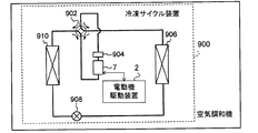
- FIG. 1 is a schematic view showing a configuration example of an air conditioner (including a refrigeration cycle device 900) of the embodiment.
- the refrigeration cycle device 900 can perform a heating operation or a cooling operation by the switching operation of the four-way valve 902.
- the refrigerant is pressurized by the compressor 904 and sent out, and the four-way valve 902, the indoor heat exchanger 906, the expansion valve 908, the outdoor heat exchanger 910 and the four-way valve 902. It returns to the compressor 904 through.
- the refrigerant is pressurized by the compressor 904 and sent out, and the four-way valve 902, the outdoor heat exchanger 910, the expansion valve 908, the indoor heat exchanger 906 and the four-way valve 902. It returns to the compressor 904 through.
- the heat exchanger 906 acts as a condenser to release heat (heats the room), and the heat exchanger 910 acts as an evaporator to absorb heat.
- the heat exchanger 910 acts as a condenser to release heat, and the heat exchanger 906 acts as an evaporator to absorb heat (cool the room).
- the expansion valve 908 depressurizes the refrigerant and expands it.
- the compressor 904 is driven by an electric motor 7 whose speed is variably controlled by the electric motor drive device 2.
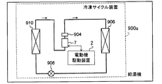
- FIG. 2 is a schematic view showing a configuration example of the heat pump type water heater (including the refrigeration cycle device 900a) of the embodiment.
- the heat exchanger 906 acts as a condenser to release heat (warms water), and the heat exchanger 910 acts as an evaporator to absorb heat.
- the compressor 904 is driven by an electric motor 7 whose speed is variably controlled by the electric motor drive device 2.
- FIG. 3 is a schematic view showing a configuration example of the refrigerator (including the refrigerating cycle device 900b) of the embodiment.
- the heat exchanger 910 acts as a condenser to release heat
- the heat exchanger 906 acts as an evaporator to absorb heat (cooling the inside of the refrigerator). To do).
- the compressor 904 is driven by an electric motor 7 whose speed is variably controlled by the electric motor drive device 2.
- FIG. 4 is a schematic wiring diagram showing the electric motor drive device 2 of the first embodiment of the present invention together with the electric motor 7 and the AC power supply 4.
- the electric motor drive device 2 is for driving the electric motor 7.
- the electric motor driving device 2 includes an inverter 30, a connection switching device 60, and a control device 100.
- the electric motor drive device 2 includes AC power input terminals 2a and 2b, a reactor 8, a rectifier circuit 10, a capacitor 20, a control power generation circuit 80, a bus current detecting means 85, and an electric amount detecting unit 90. May be provided.
- the connection switching device 60 has switches (switch circuits) 61 to 63, and by performing the switching operation of the switching devices 61 to 63 during the rotation operation of the electric motor 7, the connection state of the windings 71 to 73 of the electric motor 7 ( (Connection state) is switched.
- the inverter 30 applies an AC voltage to the windings 71 to 73 via the switches 61 to 63, and receives a counter electromotive voltage from the windings 71 to 73 of the electric motor 7 rotating via the switches 61 to 63. It is applied.
- the control device 100 controls the rotational operation of the electric motor 7 by controlling the inverter 30. Further, the control device 100 causes the connection switching device 60 to switch the connection state of the windings.
- the value of the alternating current flowing through the windings 71 to 73 (the first effective value) is the value of the alternating current flowing through the windings before the switching operation of the switches 61 to 63.
- the switching operation of the switches 61 to 63 is executed within the current control period Pc (also referred to as “zero current control period”) which is closer to zero than (second effective value).
- the connection state of the winding includes both the connection state of the winding (for example, Y connection and ⁇ connection) and the number of turns of the winding.
- the switching of the number of turns of the winding will be described in the third embodiment.
- the current control period Pc can be set to several hundred milliseconds or less.
- the current control period Pc can be set to several milliseconds or less.
- the electric motor 7 is used as a compressor of a refrigerating cycle device such as an air conditioner, a heat pump type water heater, or a refrigerator, the current control period Pc can be set within a range of several msec to 1 second.
- the control device 100 includes, for example, a memory as a storage device for storing control information as a software program, and a CPU (Central Processing Unit) as an information processing device for executing this program. It is composed of a microcomputer (microcomputer) equipped with a device, a DSP (Digital Signal Processor), or the like. Further, the control device 100 may be composed of dedicated hardware (for example, a processing circuit). Hereinafter, a case where the control device 100 is composed of a microcomputer will be described.
- the AC power input terminals 2a and 2b are connected to the external AC power supply 4.
- An AC voltage is applied from the AC power supply 4 to the AC power supply input terminals 2a and 2b.
- the applied voltage has, for example, an amplitude (effective value) of 100 V or 200 V or the like, and a frequency of 50 Hz or 60 Hz or the like.
- the rectifier circuit 10 generates a DC voltage by receiving AC power from the AC power supply 4 via the input terminals 2a and 2b and the reactor 8 and rectifying the rectifier.
- the rectifier circuit 10 is a full-wave rectifier circuit formed by bridging rectifier elements 11 to 14 such as diodes.
- the capacitor 20 smoothes the DC voltage generated by the rectifier circuit 10 and outputs the DC voltage V20.
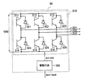
- FIG. 5 is a diagram showing the configuration of the inverter 30 of FIG. As shown in FIG. 5, the inverter 30 has an inverter main circuit 310 and a drive circuit 350. The input terminal of the inverter main circuit 310 is connected to the electrode of the capacitor 20. The line connecting the output of the rectifier circuit 10, the electrode of the capacitor 20, and the input terminal of the inverter main circuit 310 is called a DC bus.
- the inverter 30 is controlled by the control device 100, and the switching elements 311 to 316 of the six arms of the inverter main circuit 310 operate on and off. By this on / off operation, the inverter 30 generates a three-phase alternating current having a variable frequency and a variable voltage, and supplies the three-phase alternating current to the motor 7. Rectifying elements 321 to 326 for reflux are connected in parallel to the switching elements 311 to 316, respectively.
- the motor 7 is a three-phase permanent magnet synchronous motor, and the end of the stator winding (hereinafter also referred to as “winding”) is pulled out to the outside of the motor 7, and star connection (Y connection) and delta connection (Y connection) and delta connection ( It is possible to switch to any of ( ⁇ connection).
- This switching is performed by the connection switching device 60.
- the connection switching device 60 When the Y connection is referred to as the first connection, the ⁇ connection is the second connection, and when the ⁇ connection is referred to as the first connection, the Y connection is the second connection.
- the connection state of the winding may be three or more types.
- FIG. 6 is a wiring diagram showing the stator winding and the connection switching device 60 of the electric motor 7 in more detail.
- the first ends 71a, 72a, 73a of the three-phase windings 71, 72, 73 of the electric motor 7 composed of the U phase, the V phase, and the W phase are the external terminals 71c, It is connected to 72c and 73c, respectively.
- the second ends 71b, 72b, 73b of the U-phase, V-phase, and W-phase windings 71, 72, and 73 of the electric motor 7 are connected to the external terminals 71d, 72d, and 73d, respectively.
- the electric motor 7 can be connected to the connection switching device 60.
- the U-phase, V-phase, and W-phase output lines of the inverter 30 are connected to the external terminals 71c, 72c, and 73c.
- connection switching device 60 is composed of switching devices 61 to 63.
- switching devices 61, 62, 63 an electromagnetic contactor whose contacts are opened and closed electromagnetically is used.
- Such magnetic contactors include what are called relays, contactors and the like.
- FIG. 7 is a wiring diagram showing a configuration example of the switches 61 to 63.
- the switches 61 to 63 are configured as shown in FIG. 7, for example, and have different connections depending on whether a current is flowing through the exciting coils 611, 621, 631 and when no current is flowing. Take the state.
- the exciting coils 611, 621 and 631 are connected via the semiconductor switch 604 so as to receive the switching power supply voltage V60.
- the opening and closing of the semiconductor switch 604 is controlled by the switching control signal Sc output from the control device 100. If the current supply from the microcomputer included in the control device 100 is sufficiently secured, the operation may be performed so that the current flows directly from the microcomputer to the exciting coil.
- the common contact 61c of the switch 61 is connected to the external terminal 71d via the lead wire 61e.
- the normally closed contact 61b is connected to the neutral point node 64, and the normally open contact 61a is connected to the V-phase output line 332 of the inverter 30.
- the common contact 62c of the switch 62 is connected to the external terminal 72d via the lead wire 62e.
- the normally closed contact 62b is connected to the neutral point node 64, and the normally open contact 62a is connected to the W phase output line 333 of the inverter 30.
- the common contact 63c of the switch 63 is connected to the external terminal 73d via the lead wire 63e.
- the normally closed contact 63b is connected to the neutral point node 64, and the normally open contact 63a is connected to the U-phase output line 331 of the inverter 30.
- the switches 61, 62, 63 are switched to the normally closed contact side, that is, the common contacts 61c, 62c, as shown in FIG. , 63c are connected to the normally closed contacts 61b, 62b, 63b.
- the electric motor 7 is in the Y connection state.
- the switches 61, 62, 63 are switched to the normally open contact side, that is, the common contacts 61c, 62c, 63c are in the opposite direction of the drawing. It is in a state of being connected to the normally open contacts 61a, 62a, 63a. In this state, the electric motor 7 is in the ⁇ connection state.
- FIG. 8A conceptually shows the connection state of the winding when the Y connection is made
- FIG. 8B conceptually shows the connection state of the winding when the ⁇ connection is made.
- the electric power is connected at the time of Y connection and the time of ⁇ connection.
- the power supplied to is equal to each other. That is, when the electric power supplied to the electric motor is equal to each other, the current is larger in the ⁇ connection and the voltage required for driving is lower.
- connection state when the load is low, the Y connection may be used for low-speed operation, and when the load is high, the ⁇ connection may be used for high-speed operation. By doing so, the efficiency at low load can be improved, and the output at high load can be increased.
- the electric motor 7 for driving the compressor of the air conditioner As the electric motor 7 for driving the compressor of the air conditioner, a synchronous motor having a permanent magnet in the rotor is widely used in order to meet the demand for energy saving. Further, in recent air conditioners, when the difference between the room temperature and the set temperature is large, the room temperature is quickly brought closer to the set temperature by high-speed operation of rotating the electric motor 7 at a high speed, and when the room temperature is close to the set temperature, the electric motor is used. Room temperature is maintained by low-speed operation in which 7 is rotated at a low speed. When controlled in this way, the ratio of the low-speed operation time to the total operation time is large.
- connection state it is conceivable to switch the connection state according to the number of rotations. For example, when high-speed operation is required, the ⁇ connection state is set. By doing so, the voltage required for driving can be reduced to 1 / ⁇ 3 (compared to the Y connection). Therefore, it is not necessary to reduce the number of turns of the winding, and it is not necessary to use the weakening magnetic flux control.
- the current value can be reduced to 1 / ⁇ 3 compared to the ⁇ connection by setting the Y connection state.
- the winding can be designed to be suitable for driving at a low speed in the Y connection state, and the current value can be reduced as compared with the case where the Y connection is used over the entire speed range. ..
- the loss of the inverter 30 can be reduced and the efficiency can be improved.
- connection switching device 60 is provided in order to enable such switching.
- the bus current detecting means 85 shown in FIG. 4 detects the bus current, that is, the DC current Idc input to the inverter 30.
- the bus current detecting means 85 includes a shunt resistor inserted in the DC bus and supplies an analog signal indicating the detection result to the control device 100. This signal (detection signal) is converted into a digital signal by an A / D (Analog to Digital) converter (not shown) in the control device 100 and used for processing inside the control device 100.
- a / D Analog to Digital
- control device 100 controls the switching of the connection state by the connection switching device 60 and also controls the operation of the inverter 30.
- the control device 100 generates PWM (Pulse Width Modulation) signals Sm1 to Sm6 and supplies them to the inverter 30.
- the inverter 30 includes a drive circuit 350 in addition to the inverter main circuit 310, and the drive circuit 350 generates drive signals Sr1 to Sr6 based on the PWM signal.
- the drive circuit 350 controls the switching elements 311 to 316 to be turned on and off by the drive signals Sr1 to Sr6, whereby a three-phase AC voltage having a variable frequency and a variable voltage is applied to the motor 7.
- the drive signals Sr1 to Sr6 are voltage levels required to control the switching elements 311 to 316, for example. , A signal having a magnitude from + 15V to -15V. Further, the PWM signals Sm1 to Sm6 use the ground potential of the control device 100 as a reference potential, whereas the drive signals Sr1 to Sr6 are the potentials of the negative terminals (emitter terminals) of the corresponding switching elements. Is the reference potential.
- FIG. 9 is a functional block diagram showing an example of the control device 100 of FIG. As shown in FIG. 9, the control device 100 includes an operation control unit 102 and an inverter control unit 110.
- the operation control unit 102 outputs an instruction signal based on the command signal Qe provided by the electric energy detection unit 90.
- the electric amount detection unit 90 transmits a command signal based on the electric amount of an electric signal indicating the room temperature (temperature of the air-conditioned space) detected by a temperature sensor (not shown), and instruction information from an operation unit (for example, a remote control) (not shown). It receives the indicated command signal and controls the operation of each part of the air conditioner.
- the instructions from the operation unit include information indicating the set temperature, selection of the operation mode, instructions for starting and ending the operation, and the like.
- the operation control unit 102 determines, for example, whether the stator winding of the motor 7 is Y-connected or ⁇ -connected, and determines the target rotation speed, and based on the determination, the switching control signal Sc and the frequency command value ⁇ * Output. For example, when the difference between the room temperature and the set temperature is large, it is decided to make a ⁇ connection, the target rotation speed is set to a relatively high value, and after startup, the frequency is gradually increased to the frequency corresponding to the above target rotation speed. Outputs the rising frequency command value ⁇ *.
- the inverter control unit 110 includes a current restoration unit 111, a three-phase two-phase conversion unit 112, a frequency compensation unit 113, a primary frequency calculation unit 114, a voltage command calculation unit 115, and a two-phase three-phase conversion unit. It has 116, a PWM generation unit 117, an electric angle phase calculation unit 118, and an exciting current command control unit 119.
- the current restoration unit 111 restores the phase currents i u , iv , i w flowing through the motor 7 based on the value of the direct current Idc detected by the bus current detecting means 85 (FIG. 4).
- the current restoring unit 111 samples the DC current Idc detected by the bus current detecting means 85 at a timing determined based on the PWM signal provided by the PWM generating unit 117, thereby causing the phase currents i u , iv , and so on. Restore i w.
- the three-phase two-phase conversion unit 112 uses the electric angle phase ⁇ generated by the electric angle phase calculation unit 118, which will be described later, for the current values of the phase currents i u , iv , and i w restored by the current restoration unit 111.
- the exciting current component also referred to as “ ⁇ -axis current”
- the torque current component also referred to as “ ⁇ -axis current”
- the exciting current command control unit 119 obtains the optimum exciting current command value i ⁇ * that is most efficient for driving the electric motor 7 based on the torque current component ( ⁇ -axis current) i ⁇ .
- the torque current component i [delta] seeking the exciting current command value i gamma *
- exciting current component i gamma exciting current command value i gamma based on the frequency command value omega *
- the same effect can be obtained by obtaining *.
- the output current is equal to or higher than a predetermined value (or maximum) based on the torque current component i ⁇ (or the exciting current component i ⁇ , the frequency command value ⁇ *), that is, the current value is set.
- the exciting current command value i ⁇ * is output so that the current phase angle ⁇ m (not shown) is equal to or less than (or the minimum) a predetermined value.
- FIG. 10 is a diagram showing the voltage command calculation unit 115 of FIG. 9 in detail.
- the voltage command calculation unit 115 includes the ⁇ -axis current i ⁇ and the ⁇ -axis current i ⁇ obtained from the three-phase two-phase conversion unit 112, the frequency command value ⁇ *, and the excitation current command control. Based on the exciting current command value i ⁇ * obtained from unit 119, the voltage command values V ⁇ * and V ⁇ * are output.
- the controller 1152 is, for example, a proportional integration (PI) controller, and frequency estimation is performed based on the difference ( ⁇ * - ⁇ est) between the frequency command value ⁇ * and the frequency estimation value ⁇ est generated by the frequency estimation unit 1151. Outputs the ⁇ -axis current command value i ⁇ * such that the value ⁇ est matches the frequency command value ⁇ * .
- PI proportional integration
- the frequency estimation unit 1151 estimates the frequency of the electric motor 7 based on the ⁇ -axis currents i ⁇ and the ⁇ -axis currents i ⁇ and the voltage command values V ⁇ * and V ⁇ *, and generates a frequency estimation value ⁇ est.
- the switching unit 1155 selects the value of the ⁇ -axis current command value i ⁇ ** from either the ⁇ -axis current command value i ⁇ * or 0.
- the controller 1156 such as the PI controller sets the ⁇ -axis current. i [delta] and outputs a * a [delta] -axis voltage value V [delta] as to coincide with the [delta] -axis current value i [delta] **.
- the switching unit 1153 selects the value of the ⁇ -axis current command value i ⁇ ** from either the ⁇ -axis current command value i ⁇ * or 0.
- the controller 1154 such as the PI controller sets the ⁇ -axis current.
- i gamma outputs a * a gamma-axis voltage command value V gamma to match the gamma-axis current value i gamma **.
- the two-phase three-phase conversion unit 116 shown in FIG. 9 has a ⁇ -axis voltage command value V ⁇ * and a ⁇ -axis voltage command value V ⁇ * (voltage command value in a two-phase coordinate system) obtained by the voltage command calculation unit 115. Is converted into the output voltage command value (three-phase voltage command value) V u * , V v * , V w * of the three-phase coordinate system using the electric angle phase ⁇ obtained by the electric angle phase calculation unit 118 and output. To do.
- the PWM generation unit 117 generates and outputs PWM signals Sm1 to Sm6 based on the three-phase voltage command values V u * , V v * , and V w * obtained from the two-phase three-phase conversion unit 116.
- the stop signal St provided by the operation control unit 102 is given to, for example, the PWM generation unit 117, and the PWM generation unit 117 immediately stops the output of the PWM signals Sm1 to Sm6 when the stop signal St is received.
- the drive circuit 350 shown in FIG. 5 generates drive signals Sr1 to Sr6 based on the PWM signals Sm1 to Sm6.
- the configuration for restoring the phase currents i u , iv , i w from the DC current Idc on the input side of the inverter 30 is described, but the output lines 331, 332, and 333 of the inverter 30 are used.
- a current detector may be provided, and the current detector may be used to detect the phase current. In this case, the current detected by the current detector may be used instead of the current restored by the current restoration unit 111.
- phase currents i u, i v, and i w or DC current Idc is supplied to the control unit 100, when an excessive current flows to the motor 7, to the motor 7 by stopping the PWM signal Sm1 ⁇ Sm6 By stopping the energization, it is possible to prevent irreversible demagnetization.
- the current value at which irreversible demagnetization occurs in the Y connection and ⁇ connection (I Y and I ⁇ in FIG. 8). ) Is approximately ⁇ 3 times different, and the ⁇ connection is ⁇ 3 times higher than the Y connection. Therefore, if the protection level of irreversible demagnetization is set according to the Y connection, the protection of I ⁇ will be applied quickly, and it will be difficult to expand the operating range. Therefore, by switching the protection level according to the Y connection and the ⁇ connection in the control device 100, it is possible to reliably protect the motor 7 from irreversible demagnetization in each winding, and the motor drive device with improved reliability. Can be obtained.
- the magnetic force in the initial state of the motor 7 is set to 100%, and the current value (for example, the magnetic force is reduced to 97%) within a range that does not affect the performance when irreversible demagnetization occurs. It can be set to the current value), but there is no problem even if the set current value of the protection level is changed according to the equipment to be used.
- the power supply from the inverter 30 to the electric motor 7 is stopped before the connection switching device 60 is operated, and the rotation speed Nm of the electric motor 7 is zero (that is, the rotation operation is stopped). By doing so, switching can be performed without generating an arc discharge between the contacts of the switches 61, 62, and 63.
- the rotation speed Nm of the electric motor 7 when the load applied to the electric motor 7 when the electric motor 7 is restarted is, for example, the compressor 904 (FIG. 1), the state of the refrigerant is not stable. Therefore, the torque required for restarting increases, the current at startup increases, and in the worst case, restarting may not be possible. Therefore, it is necessary to restart the electric motor 7 after a lapse of time until the state of the refrigerant is sufficiently stabilized without operating the electric motor 7. Therefore, the compressor 904 cannot pressurize the refrigerant, which may cause the room temperature to rise or fall due to a decrease in cooling or heating capacity, and the room temperature may not be kept constant.
- the value (effective value) of the current flowing through the winding of the electric motor 7 or the connection switching device 60 during the rotational operation (during operation) of the electric motor 7 is controlled so as to approach zero (current).
- the power supply from the inverter 30 to the motor 7 is stopped (power supply stop period Ps), and in that state (during the power supply stop period Ps), the switch of the connection switching device 60 is operated. Switching is completed without generating an arc discharge or an excessive current between the contacts of the switches 61, 62, 63.
- the current control period Pc is a period in which the inverter applies an AC voltage to the motor so as to cancel the counter electromotive voltage generated by the rotational operation of the motor 7. In this way, the value (effective value) of the current flowing through the winding of the electric motor 7 can be brought close to zero without making the rotation speed Nm of the electric motor 7 zero, that is, without stopping the rotation operation.
- the voltage supply from the inverter 30 to the connection switching device 60 is stopped, so that the windings 71 to 73 are connected in a state where the reliability is further improved. Can be switched.
- the voltage command calculation unit 115 is operated by the switching unit 1155 to select 0 for the delta-axis current command value i ⁇ ** , so that the delta-axis current i ⁇ becomes the delta-axis current command value i ⁇ * .
- the voltage command calculation unit 115 is operated by the switching unit 1153 to select 0 for the ⁇ -axis current command value i ⁇ ** , so that the ⁇ -axis current i ⁇ matches the ⁇ -axis current command value i ⁇ *.
- the ⁇ -axis voltage command value V ⁇ * is output so that the ⁇ -axis current command value i ⁇ ** matches 0. After that, by stopping the output of the PWM signals Sm1 to Sm6, the voltage output by the inverter 30 is stopped.
- ⁇ 1-4 Effect of the first embodiment
- the current flowing in the winding of the electric motor 7, that is, the value (effective value) of the current flowing in the switches 61 to 63 is controlled by the current shown in FIG.
- control to approach zero preferably control to make it zero
- the switching operation of the switching devices 61 to 63 can be performed in a state where no current is flowing through the switching devices 61 to 63, and an arc discharge is not generated between the contacts of the switching devices 61 to 63. Therefore, when a mechanical relay is used as the switches 61 to 63, contact welding can be prevented and a highly reliable electric motor drive device can be realized.
- the "control to make zero” here does not mean that the value (effective value) of the current flowing through the switches 61 to 63 is made exactly zero, but it is so zero that it can be regarded as substantially zero. It means that it is close to.
- a voltage is supplied by the inverter 30 in order to cancel the induced voltage of the electric motor 7, and in that state, the normally open contacts 61a to 63a, the normally closed contacts 61b to 63b, and the common contacts 61c to 63c have low impedance. If two or more of the connected states are generated, a short-circuit current is generated, and an excessive current may flow to the switches 61 to 63.
- the switching operations of the switches 61 to 63 are performed during the power supply stop period Ps after the current control period Pc has elapsed, the switching can be performed without causing a large current change of the drive current supplied to the winding. .. That is, in the connection switching device 60 of the first embodiment, the first effective value of the alternating current flowing in the winding is closer to zero than the second effective value of the alternating current flowing in the winding before the switching operation of the switching device. It has a first stage having a current control period Pc and a second stage having a power supply stop period for stopping the AC voltage output by the inverter, and during the period of the second stage, the switching operation of the switch is provided. To execute.
- the second stage is a stage after (for example, immediately after) the first stage. Therefore, sudden changes in the electric motor 7 due to switching can be suppressed, and the connection state can be switched while suppressing noise and vibration of the electric motor 7.
- the current is not output during the current control period Pc period, the torque for driving the motor 7 is not generated, and the voltage is not applied to the motor 7 even during the power supply stop period Ps, so that the motor 7 is driven. No torque is generated. Therefore, in the case of an air conditioner, the electric motor 7 is decelerated according to the magnitude of the load of the compressor that compresses the refrigerant and the moment of inertia of the compressor.
- the operating time of the switches 61 to 63 is at most about 10 milliseconds.
- the switching operation can be completed in 100 milliseconds or less at the longest, so that no significant deceleration occurs. That is, the rotation speed of the electric motor 7 is appropriately set according to the load and moment of inertia of the compressor, the current control period Pc and the power supply stop period Ps are appropriately set, or a combination thereof. It is possible to complete the switching operation and continue the rotation without significantly reducing the number. This makes it possible to suppress an increase or decrease in room temperature due to the shutdown of the compressor.
- the current control period is 1 second or less
- the power supply stop period is 1 second or less
- the control device 100 of the first embodiment when the electric motor 7 is rotating at a high speed, the value of the current flowing through the electric motor 7 or the connection switching device 60 (for example, an effective value) is brought close to zero (desirably). Controls (so that it becomes substantially 0), and after confirming that the current has become sufficiently zero, it operates to stop the energization of the inverter 30. It is controlled so that the switching operations of the switching devices 61 to 63 of the connection switching device 60 are performed while the power supply of the inverter 30 is stopped. When the current flowing through the winding of the electric motor 7 is extremely low (light load state), the inverter 30 may be operated so as to stop energization without performing zero current control.
- connection switching device 60 it is possible to suppress the generation of noise and vibration due to the change in the current during the switching operation of the switches 61 to 63. Further, when a mechanical relay is used for the connection switching device 60, it is possible to prevent failures such as contact welding, and a highly reliable electric motor drive device can be obtained.
- the electric motor drive device 2 of the first embodiment is a product because the failure occurrence rate can be reduced and the life of the device can be extended even when the connection switching device 60 is configured with inexpensive parts. The cost can be reduced.
- the protection level is switched to delta connection, but it is assumed that the motor 7 is still in the state of Y connection because it is in the process of switching to delta connection. Will be done. In that case, if an excessive current flows by mistake, irreversible demagnetization of the electric motor 7 may occur.
- the Y connection having a low protection level is used.
- the protection level it is possible to protect from irreversible demagnetization regardless of whether the connection is Y or ⁇ when the connection is switched. Needless to say, since the current is controlled to be zero when the connection is switched, there is no effect on the operation of the electric motor 7.
- the magnetic force in the initial state of the motor 7 is set to 100%, and the current value (for example, the magnetic force) is within a range that does not affect the performance when irreversible demagnetization occurs. (Current value that drops to 97%) can be set, and by setting the current value in ⁇ connection to ⁇ 3 times the value of Y connection, it is surely protected from irreversible demagnetization regardless of the connection state. It becomes possible to do.
- the current value of I ⁇ ⁇ ⁇ 3 (the current value of the protection level in the Y connection). It is desirable to set (equivalent to) as the protection level. There is no problem even if the set current value of the protection level is changed according to the equipment to be used.
- a diode or the like is generally used as the rectifying elements 11 to 14 of the rectifying circuit 10.
- the configuration of the rectifier circuit 10 is not limited to the example of FIG.
- a transistor element semiconductor switch
- MOSFET Metal-Oxide-Semiconductor Field-Effective-Transistor
- the voltage supplied from the AC power supply 4 It may be configured to perform rectification by turning it on according to the polarity of (input AC voltage).
- IGBTs Insulated Gate Bipolar Transistors
- MOSFETs Insulated Gate Bipolar Transistors
- the switching elements 311 to 316 any elements that can perform switching may be used.
- MOSFETs When MOSFETs are used as switching elements 311 to 316, it is not necessary to connect rectifying elements 321 to 326 (FIG. 5) for circulation in parallel because the MOSFET has a parasitic diode due to its structure.
- the materials constituting the rectifying elements 11 to 14 and the switching elements 311 to 316 are not only silicon (Si) but also silicon carbide (SiC), gallium nitride (GaN), diamond, etc., which are wide bandgap semiconductors. It is possible to reduce the loss by configuring with.
- connection switching device 260 is used instead of the connection switching device 60.
- the changeover switches 61 to 63 of the connection changeover device 60 use changeover switches (selection switches).
- each switch of the connection switching device 260 is composed of a combination of a normally closed switch and a normally opened switch, that is, a combination of an on / off type switch.
- FIG. 12 is a wiring diagram showing the windings 71 to 73 of the electric motor 7 and the connection switching device 260 according to the second embodiment.
- the changeover device 61 is composed of a combination of the normally closed switch 615 and the normally open switch 616
- the changeover 62 is composed of the combination of the normally closed switch 625 and the normally open switch 626 for switching. It is composed of a combination of a normally closed switch 635 and a normally opened switch 636 of the vessel 63.
- an electromagnetic contactor can be used as each switch. it can.
- An electromagnetic contactor is suitable because it has a small conduction loss when it is turned on.
- each switch may be configured by using a semiconductor switch.
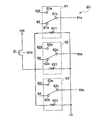
- FIG. 13 is a circuit diagram showing a configuration example in which a MOS transistor is used for the switch 61 (62, 63) of the connection switching device 260 of FIG.
- FIG. 13 shows one of the switches 61, 62, 63.
- the switches 61, 62, and 63 have the same configuration as each other and operate in the same manner.
- FIG. 14 is a diagram showing an example of an on / off state of the MOS transistor of the switch of FIG. 13 in tabular form.
- the switch 61 is a MOS transistor 616a (626a, 626a,) connected in series between the lead wire 61e (62e, 63e) and the output wire 332 (333,331).
- the switch 61 (62, 63) includes a MOS transistor 615a (625a, 635a) and a diode 615c (625c, 635c) connected in series between the lead wire 61e (62e, 63e) and the neutral point node 64.
- a MOS transistor 615b (625b, 635b) and a diode 615d (625d, 635d) connected in series between the lead wire 61e (62e, 63e) and the neutral point node 64.
- each MOS transistor 616a (626a, 636a), 616b (626b, 636b), 615a (625a, 635a), 615b (625b, 635b)
- the anode is connected to the diode and the cathode is the lead wire (or neutral point node or It has a parasitic diode connected to the output line).
- MOS transistors 616a, 626a, 636a are turned on, MOS transistors 616b, 626b, 636b are turned on, MOS transistors 615a, 625a, 635a are turned off, and MOS transistors 615b, 625b, 635b are turned off.
- the windings 71 to 73 can be connected by ⁇ .
- the MOS transistors 616a, 626a, 636a are turned off, the MOS transistors 616b, 626b, 636b are turned off, the MOS transistors 615a, 625a, 635a are turned on, and the MOS transistors 615b, 625b, 635b are turned on.
- the windings 71 to 73 can be Y-connected.
- the MOS transistor as a semiconductor switch is composed of a wide bandgap (WBG) semiconductor.
- the WBG semiconductor is, for example, a semiconductor containing silicon carbide (SiC), gallium nitride (GaN), gallium oxide (Ga2O3), and diamond as constituent materials.
- SiC silicon carbide
- GaN gallium nitride
- Ga2O3 gallium oxide
- diamond diamond
- connection switching device 260 made of a semiconductor, the normally closed switch 615, 625, 635 and the normally open switch 616, 626, 636 are switched within the power supply stop period Ps after the current control period Pc shown in FIG.
- the connection state can be switched while suppressing noise and vibration.
- connection switching device 260 when a mechanical relay is used for the connection switching device 260, failures such as contact welding can be prevented, and a highly reliable electric motor drive device can be obtained.
- connection switching device 260 when a semiconductor switch is used for the connection switching device 260, a failure due to heat generation of the semiconductor switch can be prevented, and a highly reliable electric motor drive device can be obtained.
- connection switching device 260 is configured with inexpensive parts, the failure occurrence rate can be reduced and the life of the device can be extended, so that the product cost can be extended. Can be reduced.
- the electric motor drive device of the second embodiment is the same as the electric motor drive device 2 of the first embodiment.
- Embodiment 3 Embodiment 3.
- an electric motor drive device to which the present invention is applied is connected to an electric motor 7 capable of switching windings 71 to 73 between Y connection and delta connection.
- an electric motor drive device to which the present invention is applied is connected to an electric motor 7a capable of switching the number of turns of each of the windings 71 to 73.
- the windings 71 to 73 of each phase are composed of two or more winding portions.
- the stator windings 71, 72, 73 are provided by the connection switching device 360 so that both ends of each of the two or more winding portions constituting the windings 71 to 73 of each phase can be connected to the outside of the motor 7a. (In the third embodiment, the number of turns of the winding) is switched. Further, the connection switching device to which the present invention is applied can also be applied to an electric motor capable of switching the winding portion to either parallel connection or series connection.
- the windings of each phase are composed of two winding portions, and both ends of the winding portions can be connected to the outside of the motor 7a, and the connection switching device 360 is shown.
- the configuration for switching the connection status is shown with.
- the U-phase winding 71 is composed of two winding portions 711 and 712
- the V-phase winding 72 is composed of two winding portions 721 and 722
- the W-phase winding 73 is composed of two winding portions 721 and 712. It is composed of two winding portions 731 and 732.
- the first end of the winding portion 711,721,731 is connected to the output lines 331, 332, 333 of the inverter 30 via the external terminals 71c, 72c, 73c, respectively.
- the second ends of the winding portions 711, 721 and 731 are connected to the common contacts of the changeover switches 617, 627 and 627 via the external terminals 71 g, 72 g and 73 g, respectively.
- the first end of the winding portion 712,722,732 is connected to the common contact of the changeover switches 618, 628, 638 via the external terminals 71h, 72h, 73h, respectively.
- the second ends of the winding portions 712, 722 and 732 are connected to the neutral point node 64 via the external terminals 71d, 72d and 73d, respectively.
- the normally closed contacts of the changeover switches 617, 627 and 637 are connected to the normally closed contacts of the changeover switches 618, 628 and 638, respectively.
- the normally open contacts of the changeover switches 617, 627, 637 are connected to the neutral point node 64.
- the normally open contacts of the changeover switches 618, 628, 638 are connected to the output lines 331, 332, 333 of the inverter 30.
- connection changeover device 360 is configured by the changeover switches 617, 627, 637, 618, 628, and 638.
- connection switching device 360 Even when such a connection switching device 360 is used, the switching operation of the switching device of the connection switching device 360 is performed during the current control period Pc in the same manner as that shown in the first and second embodiments. It can protect mechanical relays or semiconductor switches.
- a combination of the normally closed switch and the normally opened switch can be used instead of the changeover switch. Further, the normally closed switch and the normally opened switch can be used as a semiconductor switch.
- the electric motor drive device of an electric motor having a configuration in which an intermediate tap is provided in the winding in a Y connection or ⁇ connection and a part of the winding is short-circuited by a switching means to change the voltage required for driving.
- the present invention can be applied.
- the present invention can be applied as long as the electric motor can switch the connection state of the windings and the counter electromotive voltage can be switched by switching the connection state.
- the electric motor drive device of the third embodiment is the same as the electric motor drive device of the first or second embodiment.
- Electric motor drive device 4 AC power supply, 7, 7a electric motor, 8 reactor, 10 rectifier circuit, 20 capacitor, 30 inverter, 60, 260, 360 connection switching device, 61-63 switching device, 71-73 winding, 80 control Power generation circuit, 85 bus current detection means, 100 control device, 102 operation control unit, 110 inverter control unit, 900, 900a, 900b refrigeration cycle device, 902 four-way valve, 904 compressor, 906 heat exchanger, 908 expansion valve, 910 Heat exchanger.
Landscapes
- Engineering & Computer Science (AREA)
- Power Engineering (AREA)
- Control Of Ac Motors In General (AREA)
Priority Applications (2)
| Application Number | Priority Date | Filing Date | Title |
|---|---|---|---|
| JP2021553931A JP7325526B2 (ja) | 2019-10-29 | 2019-10-29 | 電動機駆動装置、冷凍サイクル装置、空気調和機、給湯機、及び冷蔵庫 |
| PCT/JP2019/042376 WO2021084617A1 (ja) | 2019-10-29 | 2019-10-29 | 電動機駆動装置、冷凍サイクル装置、空気調和機、給湯機、及び冷蔵庫 |
Applications Claiming Priority (1)
| Application Number | Priority Date | Filing Date | Title |
|---|---|---|---|
| PCT/JP2019/042376 WO2021084617A1 (ja) | 2019-10-29 | 2019-10-29 | 電動機駆動装置、冷凍サイクル装置、空気調和機、給湯機、及び冷蔵庫 |
Publications (1)
| Publication Number | Publication Date |
|---|---|
| WO2021084617A1 true WO2021084617A1 (ja) | 2021-05-06 |
Family
ID=75714925
Family Applications (1)
| Application Number | Title | Priority Date | Filing Date |
|---|---|---|---|
| PCT/JP2019/042376 Ceased WO2021084617A1 (ja) | 2019-10-29 | 2019-10-29 | 電動機駆動装置、冷凍サイクル装置、空気調和機、給湯機、及び冷蔵庫 |
Country Status (2)
| Country | Link |
|---|---|
| JP (1) | JP7325526B2 (https=) |
| WO (1) | WO2021084617A1 (https=) |
Cited By (2)
| Publication number | Priority date | Publication date | Assignee | Title |
|---|---|---|---|---|
| JPWO2022239113A1 (https=) * | 2021-05-11 | 2022-11-17 | ||
| IT202300010629A1 (it) * | 2023-05-25 | 2024-11-25 | Blue Airco S R L | Condizionatore |
Citations (3)
| Publication number | Priority date | Publication date | Assignee | Title |
|---|---|---|---|---|
| JP2000236700A (ja) * | 1999-02-16 | 2000-08-29 | Okuma Corp | 誘導電動機の制御装置 |
| JP2013062888A (ja) * | 2010-01-18 | 2013-04-04 | Yamaha Motor Co Ltd | 鞍乗型車両 |
| WO2019087243A1 (ja) * | 2017-10-30 | 2019-05-09 | 三菱電機株式会社 | 電動機駆動装置、冷凍サイクル装置、空気調和機、給湯機、及び冷蔵庫 |
-
2019
- 2019-10-29 WO PCT/JP2019/042376 patent/WO2021084617A1/ja not_active Ceased
- 2019-10-29 JP JP2021553931A patent/JP7325526B2/ja active Active
Patent Citations (3)
| Publication number | Priority date | Publication date | Assignee | Title |
|---|---|---|---|---|
| JP2000236700A (ja) * | 1999-02-16 | 2000-08-29 | Okuma Corp | 誘導電動機の制御装置 |
| JP2013062888A (ja) * | 2010-01-18 | 2013-04-04 | Yamaha Motor Co Ltd | 鞍乗型車両 |
| WO2019087243A1 (ja) * | 2017-10-30 | 2019-05-09 | 三菱電機株式会社 | 電動機駆動装置、冷凍サイクル装置、空気調和機、給湯機、及び冷蔵庫 |
Cited By (3)
| Publication number | Priority date | Publication date | Assignee | Title |
|---|---|---|---|---|
| JPWO2022239113A1 (https=) * | 2021-05-11 | 2022-11-17 | ||
| JP7511753B2 (ja) | 2021-05-11 | 2024-07-05 | 三菱電機株式会社 | モータ駆動装置およびそれを有する空気調和装置の室外機 |
| IT202300010629A1 (it) * | 2023-05-25 | 2024-11-25 | Blue Airco S R L | Condizionatore |
Also Published As
| Publication number | Publication date |
|---|---|
| JPWO2021084617A1 (https=) | 2021-05-06 |
| JP7325526B2 (ja) | 2023-08-14 |
Similar Documents
| Publication | Publication Date | Title |
|---|---|---|
| JP6921221B2 (ja) | 電動機駆動装置、冷凍サイクル装置、空気調和機、給湯機、及び冷蔵庫 | |
| JP6991336B2 (ja) | 電動機駆動装置及び冷凍サイクル適用機器 | |
| JP6689465B2 (ja) | 電動機駆動装置及び冷凍サイクル適用機器 | |
| US11424698B2 (en) | Motor control device and air-conditioning device | |
| WO2016203709A1 (ja) | モータ駆動装置 | |
| JP6929434B2 (ja) | 電動機駆動装置及び冷凍サイクル適用機器 | |
| JP7325526B2 (ja) | 電動機駆動装置、冷凍サイクル装置、空気調和機、給湯機、及び冷蔵庫 | |
| JP6991364B2 (ja) | モータ駆動装置、冷凍サイクル装置、空気調和機、給湯機及び冷蔵庫 | |
| JP7515574B2 (ja) | 電動機駆動装置、冷凍サイクル装置、空気調和機、給湯機、及び冷蔵庫 | |
| EP4300810B1 (en) | Electric motor drive device and refrigeration cycle application device | |
| JP7486656B2 (ja) | 電動機駆動装置、冷凍サイクル装置、空気調和機、給湯器および冷蔵庫 |
Legal Events
| Date | Code | Title | Description |
|---|---|---|---|
| 121 | Ep: the epo has been informed by wipo that ep was designated in this application |
Ref document number: 19950791 Country of ref document: EP Kind code of ref document: A1 |
|
| ENP | Entry into the national phase |
Ref document number: 2021553931 Country of ref document: JP Kind code of ref document: A |
|
| NENP | Non-entry into the national phase |
Ref country code: DE |
|
| 122 | Ep: pct application non-entry in european phase |
Ref document number: 19950791 Country of ref document: EP Kind code of ref document: A1 |