WO2021084617A1 - Electric motor drive device, refrigeration cycle device, air conditioner, water heater, and refrigerator - Google Patents
Electric motor drive device, refrigeration cycle device, air conditioner, water heater, and refrigerator Download PDFInfo
- Publication number
- WO2021084617A1 WO2021084617A1 PCT/JP2019/042376 JP2019042376W WO2021084617A1 WO 2021084617 A1 WO2021084617 A1 WO 2021084617A1 JP 2019042376 W JP2019042376 W JP 2019042376W WO 2021084617 A1 WO2021084617 A1 WO 2021084617A1
- Authority
- WO
- WIPO (PCT)
- Prior art keywords
- electric motor
- switching
- current
- connection
- inverter
- Prior art date
Links
Images


Classifications
-
- H—ELECTRICITY
- H02—GENERATION; CONVERSION OR DISTRIBUTION OF ELECTRIC POWER
- H02P—CONTROL OR REGULATION OF ELECTRIC MOTORS, ELECTRIC GENERATORS OR DYNAMO-ELECTRIC CONVERTERS; CONTROLLING TRANSFORMERS, REACTORS OR CHOKE COILS
- H02P25/00—Arrangements or methods for the control of AC motors characterised by the kind of AC motor or by structural details
- H02P25/16—Arrangements or methods for the control of AC motors characterised by the kind of AC motor or by structural details characterised by the circuit arrangement or by the kind of wiring
- H02P25/18—Arrangements or methods for the control of AC motors characterised by the kind of AC motor or by structural details characterised by the circuit arrangement or by the kind of wiring with arrangements for switching the windings, e.g. with mechanical switches or relays
-
- H—ELECTRICITY
- H02—GENERATION; CONVERSION OR DISTRIBUTION OF ELECTRIC POWER
- H02P—CONTROL OR REGULATION OF ELECTRIC MOTORS, ELECTRIC GENERATORS OR DYNAMO-ELECTRIC CONVERTERS; CONTROLLING TRANSFORMERS, REACTORS OR CHOKE COILS
- H02P27/00—Arrangements or methods for the control of AC motors characterised by the kind of supply voltage
- H02P27/04—Arrangements or methods for the control of AC motors characterised by the kind of supply voltage using variable-frequency supply voltage, e.g. inverter or converter supply voltage
- H02P27/06—Arrangements or methods for the control of AC motors characterised by the kind of supply voltage using variable-frequency supply voltage, e.g. inverter or converter supply voltage using dc to ac converters or inverters
Definitions
- the present invention relates to an electric motor drive device, a refrigeration cycle device including the electric motor drive device, and an air conditioner, a water heater, and a refrigerator equipped with the refrigeration cycle device.
- a drive wheel a motor connected so as to transmit a driving force to the drive wheel and having a switchable winding, an input unit for instructing the output of the motor, and a control signal based on an instruction from the input unit.
- the output control unit, the inverter whose duty ratio is adjusted based on the control signal from the control unit to supply the output voltage to the motor, the winding switching unit that switches the winding, and the motor current that flows through the winding are detected.
- a saddle-type vehicle including a current detection unit and a phase detection unit that detects the phase of the motor.
- the control unit of this saddle-type vehicle has a switching determination unit that determines whether or not the winding switching condition is satisfied, and a duty ratio adjustment period when the winding switching condition is satisfied, and an instruction from the input unit.
- the adjustment unit adjusts the duty ratio of the inverter based on the motor current detected by the current detection unit and the phase of the motor detected by the phase detection unit so that the motor current becomes 0 regardless of the above. It includes a switching instruction unit that instructs the winding switching unit to switch the winding during the duty ratio adjustment period (see, for example, Patent Document 1).
- JP 2013-62888 (for example, claim 1, FIGS. 2 to 6)
- the present invention has been made in view of the above, and the switching operation of the switch for switching the connection state of the windings of the electric motor can be performed without stopping the rotational operation of the electric motor, and the connection state can be switched.
- An object of the present invention is to provide an electric motor drive device which is less likely to cause a failure due to the failure and a device provided with the electric motor drive device.
- the electric motor drive device includes a connection switching device that has a switching device and switches the connection state of the windings of the electric motor by performing the switching operation of the switching device during the rotation operation of the electric motor, and the switching device.
- An AC voltage is applied to the winding through the winding, and a countercurrent voltage is applied from the winding of the electric motor in rotation operation via the switch, and the electric motor is controlled by controlling the inverter.
- It has a control device that controls the rotation operation and causes the connection switching device to switch the connection state, and the first effective value of the alternating current flowing through the winding is before the switching operation of the switching device.
- the first stage having a current control period closer to zero than the second effective value of the AC current flowing through the winding, and the stage after the first stage, the AC voltage output by the inverter is stopped.
- a second stage having a power supply stop period is provided, and the switching operation of the switch is executed during the period of the second stage.
- a period for stopping the energization of the inverter is provided, and the connection switching device is switched within that period. Since the device is switched, the connection switching device is less likely to fail, and the life of the motor drive device can be extended.
- connection state of the winding is switched during the current control period in which the rotational operation of the electric motor is not stopped. Therefore, it is not necessary to suspend the rotational operation of the motor and then restart the motor in order to switch the connection state of the windings.
- FIG. 1 and (b) are diagrams conceptually showing windings of electric motors in different wiring states.
- FIG. It is a functional block diagram which shows an example of the control apparatus used in Embodiment 1.
- FIG. It is a figure which shows the voltage command calculation part of FIG. 9 in detail.
- FIG. It is a waveform figure which shows the operation of the electric motor drive device of Embodiment 1.
- FIG. It is a wiring diagram which shows the winding of the electric motor and the connection switching device in Embodiment 2 of this invention.
- It is a circuit diagram which shows the configuration example which used the MOS transistor for the switch of the connection switching device of FIG.
- an electric motor drive device according to an embodiment of the present invention, a refrigerating cycle device including the refrigerating cycle applicable device, an air conditioner equipped with the refrigerating cycle device, and a hot water supply.
- the machine and the refrigerator will be described.
- the embodiments shown below are merely examples, and the electric motor drive device and each device provided with the electric motor drive device can be modified in various ways within the scope of the present invention.
- the components with the same reference numerals have the same or similar functions.
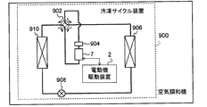
- FIG. 1 is a schematic view showing a configuration example of an air conditioner (including a refrigeration cycle device 900) of the embodiment.
- the refrigeration cycle device 900 can perform a heating operation or a cooling operation by the switching operation of the four-way valve 902.
- the refrigerant is pressurized by the compressor 904 and sent out, and the four-way valve 902, the indoor heat exchanger 906, the expansion valve 908, the outdoor heat exchanger 910 and the four-way valve 902. It returns to the compressor 904 through.
- the refrigerant is pressurized by the compressor 904 and sent out, and the four-way valve 902, the outdoor heat exchanger 910, the expansion valve 908, the indoor heat exchanger 906 and the four-way valve 902. It returns to the compressor 904 through.
- the heat exchanger 906 acts as a condenser to release heat (heats the room), and the heat exchanger 910 acts as an evaporator to absorb heat.
- the heat exchanger 910 acts as a condenser to release heat, and the heat exchanger 906 acts as an evaporator to absorb heat (cool the room).
- the expansion valve 908 depressurizes the refrigerant and expands it.
- the compressor 904 is driven by an electric motor 7 whose speed is variably controlled by the electric motor drive device 2.
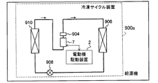
- FIG. 2 is a schematic view showing a configuration example of the heat pump type water heater (including the refrigeration cycle device 900a) of the embodiment.
- the heat exchanger 906 acts as a condenser to release heat (warms water), and the heat exchanger 910 acts as an evaporator to absorb heat.
- the compressor 904 is driven by an electric motor 7 whose speed is variably controlled by the electric motor drive device 2.
- FIG. 3 is a schematic view showing a configuration example of the refrigerator (including the refrigerating cycle device 900b) of the embodiment.
- the heat exchanger 910 acts as a condenser to release heat
- the heat exchanger 906 acts as an evaporator to absorb heat (cooling the inside of the refrigerator). To do).
- the compressor 904 is driven by an electric motor 7 whose speed is variably controlled by the electric motor drive device 2.
- FIG. 4 is a schematic wiring diagram showing the electric motor drive device 2 of the first embodiment of the present invention together with the electric motor 7 and the AC power supply 4.
- the electric motor drive device 2 is for driving the electric motor 7.
- the electric motor driving device 2 includes an inverter 30, a connection switching device 60, and a control device 100.
- the electric motor drive device 2 includes AC power input terminals 2a and 2b, a reactor 8, a rectifier circuit 10, a capacitor 20, a control power generation circuit 80, a bus current detecting means 85, and an electric amount detecting unit 90. May be provided.
- the connection switching device 60 has switches (switch circuits) 61 to 63, and by performing the switching operation of the switching devices 61 to 63 during the rotation operation of the electric motor 7, the connection state of the windings 71 to 73 of the electric motor 7 ( (Connection state) is switched.
- the inverter 30 applies an AC voltage to the windings 71 to 73 via the switches 61 to 63, and receives a counter electromotive voltage from the windings 71 to 73 of the electric motor 7 rotating via the switches 61 to 63. It is applied.
- the control device 100 controls the rotational operation of the electric motor 7 by controlling the inverter 30. Further, the control device 100 causes the connection switching device 60 to switch the connection state of the windings.
- the value of the alternating current flowing through the windings 71 to 73 (the first effective value) is the value of the alternating current flowing through the windings before the switching operation of the switches 61 to 63.
- the switching operation of the switches 61 to 63 is executed within the current control period Pc (also referred to as “zero current control period”) which is closer to zero than (second effective value).
- the connection state of the winding includes both the connection state of the winding (for example, Y connection and ⁇ connection) and the number of turns of the winding.
- the switching of the number of turns of the winding will be described in the third embodiment.
- the current control period Pc can be set to several hundred milliseconds or less.
- the current control period Pc can be set to several milliseconds or less.
- the electric motor 7 is used as a compressor of a refrigerating cycle device such as an air conditioner, a heat pump type water heater, or a refrigerator, the current control period Pc can be set within a range of several msec to 1 second.
- the control device 100 includes, for example, a memory as a storage device for storing control information as a software program, and a CPU (Central Processing Unit) as an information processing device for executing this program. It is composed of a microcomputer (microcomputer) equipped with a device, a DSP (Digital Signal Processor), or the like. Further, the control device 100 may be composed of dedicated hardware (for example, a processing circuit). Hereinafter, a case where the control device 100 is composed of a microcomputer will be described.
- the AC power input terminals 2a and 2b are connected to the external AC power supply 4.
- An AC voltage is applied from the AC power supply 4 to the AC power supply input terminals 2a and 2b.
- the applied voltage has, for example, an amplitude (effective value) of 100 V or 200 V or the like, and a frequency of 50 Hz or 60 Hz or the like.
- the rectifier circuit 10 generates a DC voltage by receiving AC power from the AC power supply 4 via the input terminals 2a and 2b and the reactor 8 and rectifying the rectifier.
- the rectifier circuit 10 is a full-wave rectifier circuit formed by bridging rectifier elements 11 to 14 such as diodes.
- the capacitor 20 smoothes the DC voltage generated by the rectifier circuit 10 and outputs the DC voltage V20.
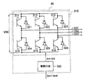
- FIG. 5 is a diagram showing the configuration of the inverter 30 of FIG. As shown in FIG. 5, the inverter 30 has an inverter main circuit 310 and a drive circuit 350. The input terminal of the inverter main circuit 310 is connected to the electrode of the capacitor 20. The line connecting the output of the rectifier circuit 10, the electrode of the capacitor 20, and the input terminal of the inverter main circuit 310 is called a DC bus.
- the inverter 30 is controlled by the control device 100, and the switching elements 311 to 316 of the six arms of the inverter main circuit 310 operate on and off. By this on / off operation, the inverter 30 generates a three-phase alternating current having a variable frequency and a variable voltage, and supplies the three-phase alternating current to the motor 7. Rectifying elements 321 to 326 for reflux are connected in parallel to the switching elements 311 to 316, respectively.
- the motor 7 is a three-phase permanent magnet synchronous motor, and the end of the stator winding (hereinafter also referred to as “winding”) is pulled out to the outside of the motor 7, and star connection (Y connection) and delta connection (Y connection) and delta connection ( It is possible to switch to any of ( ⁇ connection).
- This switching is performed by the connection switching device 60.
- the connection switching device 60 When the Y connection is referred to as the first connection, the ⁇ connection is the second connection, and when the ⁇ connection is referred to as the first connection, the Y connection is the second connection.
- the connection state of the winding may be three or more types.
- FIG. 6 is a wiring diagram showing the stator winding and the connection switching device 60 of the electric motor 7 in more detail.
- the first ends 71a, 72a, 73a of the three-phase windings 71, 72, 73 of the electric motor 7 composed of the U phase, the V phase, and the W phase are the external terminals 71c, It is connected to 72c and 73c, respectively.
- the second ends 71b, 72b, 73b of the U-phase, V-phase, and W-phase windings 71, 72, and 73 of the electric motor 7 are connected to the external terminals 71d, 72d, and 73d, respectively.
- the electric motor 7 can be connected to the connection switching device 60.
- the U-phase, V-phase, and W-phase output lines of the inverter 30 are connected to the external terminals 71c, 72c, and 73c.
- connection switching device 60 is composed of switching devices 61 to 63.
- switching devices 61, 62, 63 an electromagnetic contactor whose contacts are opened and closed electromagnetically is used.
- Such magnetic contactors include what are called relays, contactors and the like.
- FIG. 7 is a wiring diagram showing a configuration example of the switches 61 to 63.
- the switches 61 to 63 are configured as shown in FIG. 7, for example, and have different connections depending on whether a current is flowing through the exciting coils 611, 621, 631 and when no current is flowing. Take the state.
- the exciting coils 611, 621 and 631 are connected via the semiconductor switch 604 so as to receive the switching power supply voltage V60.
- the opening and closing of the semiconductor switch 604 is controlled by the switching control signal Sc output from the control device 100. If the current supply from the microcomputer included in the control device 100 is sufficiently secured, the operation may be performed so that the current flows directly from the microcomputer to the exciting coil.
- the common contact 61c of the switch 61 is connected to the external terminal 71d via the lead wire 61e.
- the normally closed contact 61b is connected to the neutral point node 64, and the normally open contact 61a is connected to the V-phase output line 332 of the inverter 30.
- the common contact 62c of the switch 62 is connected to the external terminal 72d via the lead wire 62e.
- the normally closed contact 62b is connected to the neutral point node 64, and the normally open contact 62a is connected to the W phase output line 333 of the inverter 30.
- the common contact 63c of the switch 63 is connected to the external terminal 73d via the lead wire 63e.
- the normally closed contact 63b is connected to the neutral point node 64, and the normally open contact 63a is connected to the U-phase output line 331 of the inverter 30.
- the switches 61, 62, 63 are switched to the normally closed contact side, that is, the common contacts 61c, 62c, as shown in FIG. , 63c are connected to the normally closed contacts 61b, 62b, 63b.
- the electric motor 7 is in the Y connection state.
- the switches 61, 62, 63 are switched to the normally open contact side, that is, the common contacts 61c, 62c, 63c are in the opposite direction of the drawing. It is in a state of being connected to the normally open contacts 61a, 62a, 63a. In this state, the electric motor 7 is in the ⁇ connection state.
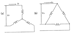
- FIG. 8A conceptually shows the connection state of the winding when the Y connection is made
- FIG. 8B conceptually shows the connection state of the winding when the ⁇ connection is made.
- the electric power is connected at the time of Y connection and the time of ⁇ connection.
- the power supplied to is equal to each other. That is, when the electric power supplied to the electric motor is equal to each other, the current is larger in the ⁇ connection and the voltage required for driving is lower.
- connection state when the load is low, the Y connection may be used for low-speed operation, and when the load is high, the ⁇ connection may be used for high-speed operation. By doing so, the efficiency at low load can be improved, and the output at high load can be increased.
- the electric motor 7 for driving the compressor of the air conditioner As the electric motor 7 for driving the compressor of the air conditioner, a synchronous motor having a permanent magnet in the rotor is widely used in order to meet the demand for energy saving. Further, in recent air conditioners, when the difference between the room temperature and the set temperature is large, the room temperature is quickly brought closer to the set temperature by high-speed operation of rotating the electric motor 7 at a high speed, and when the room temperature is close to the set temperature, the electric motor is used. Room temperature is maintained by low-speed operation in which 7 is rotated at a low speed. When controlled in this way, the ratio of the low-speed operation time to the total operation time is large.
- connection state it is conceivable to switch the connection state according to the number of rotations. For example, when high-speed operation is required, the ⁇ connection state is set. By doing so, the voltage required for driving can be reduced to 1 / ⁇ 3 (compared to the Y connection). Therefore, it is not necessary to reduce the number of turns of the winding, and it is not necessary to use the weakening magnetic flux control.
- the current value can be reduced to 1 / ⁇ 3 compared to the ⁇ connection by setting the Y connection state.
- the winding can be designed to be suitable for driving at a low speed in the Y connection state, and the current value can be reduced as compared with the case where the Y connection is used over the entire speed range. ..
- the loss of the inverter 30 can be reduced and the efficiency can be improved.
- connection switching device 60 is provided in order to enable such switching.
- the bus current detecting means 85 shown in FIG. 4 detects the bus current, that is, the DC current Idc input to the inverter 30.
- the bus current detecting means 85 includes a shunt resistor inserted in the DC bus and supplies an analog signal indicating the detection result to the control device 100. This signal (detection signal) is converted into a digital signal by an A / D (Analog to Digital) converter (not shown) in the control device 100 and used for processing inside the control device 100.
- a / D Analog to Digital
- control device 100 controls the switching of the connection state by the connection switching device 60 and also controls the operation of the inverter 30.
- the control device 100 generates PWM (Pulse Width Modulation) signals Sm1 to Sm6 and supplies them to the inverter 30.
- the inverter 30 includes a drive circuit 350 in addition to the inverter main circuit 310, and the drive circuit 350 generates drive signals Sr1 to Sr6 based on the PWM signal.
- the drive circuit 350 controls the switching elements 311 to 316 to be turned on and off by the drive signals Sr1 to Sr6, whereby a three-phase AC voltage having a variable frequency and a variable voltage is applied to the motor 7.
- the drive signals Sr1 to Sr6 are voltage levels required to control the switching elements 311 to 316, for example. , A signal having a magnitude from + 15V to -15V. Further, the PWM signals Sm1 to Sm6 use the ground potential of the control device 100 as a reference potential, whereas the drive signals Sr1 to Sr6 are the potentials of the negative terminals (emitter terminals) of the corresponding switching elements. Is the reference potential.
- FIG. 9 is a functional block diagram showing an example of the control device 100 of FIG. As shown in FIG. 9, the control device 100 includes an operation control unit 102 and an inverter control unit 110.
- the operation control unit 102 outputs an instruction signal based on the command signal Qe provided by the electric energy detection unit 90.
- the electric amount detection unit 90 transmits a command signal based on the electric amount of an electric signal indicating the room temperature (temperature of the air-conditioned space) detected by a temperature sensor (not shown), and instruction information from an operation unit (for example, a remote control) (not shown). It receives the indicated command signal and controls the operation of each part of the air conditioner.
- the instructions from the operation unit include information indicating the set temperature, selection of the operation mode, instructions for starting and ending the operation, and the like.
- the operation control unit 102 determines, for example, whether the stator winding of the motor 7 is Y-connected or ⁇ -connected, and determines the target rotation speed, and based on the determination, the switching control signal Sc and the frequency command value ⁇ * Output. For example, when the difference between the room temperature and the set temperature is large, it is decided to make a ⁇ connection, the target rotation speed is set to a relatively high value, and after startup, the frequency is gradually increased to the frequency corresponding to the above target rotation speed. Outputs the rising frequency command value ⁇ *.
- the inverter control unit 110 includes a current restoration unit 111, a three-phase two-phase conversion unit 112, a frequency compensation unit 113, a primary frequency calculation unit 114, a voltage command calculation unit 115, and a two-phase three-phase conversion unit. It has 116, a PWM generation unit 117, an electric angle phase calculation unit 118, and an exciting current command control unit 119.
- the current restoration unit 111 restores the phase currents i u , iv , i w flowing through the motor 7 based on the value of the direct current Idc detected by the bus current detecting means 85 (FIG. 4).
- the current restoring unit 111 samples the DC current Idc detected by the bus current detecting means 85 at a timing determined based on the PWM signal provided by the PWM generating unit 117, thereby causing the phase currents i u , iv , and so on. Restore i w.
- the three-phase two-phase conversion unit 112 uses the electric angle phase ⁇ generated by the electric angle phase calculation unit 118, which will be described later, for the current values of the phase currents i u , iv , and i w restored by the current restoration unit 111.
- the exciting current component also referred to as “ ⁇ -axis current”
- the torque current component also referred to as “ ⁇ -axis current”
- the exciting current command control unit 119 obtains the optimum exciting current command value i ⁇ * that is most efficient for driving the electric motor 7 based on the torque current component ( ⁇ -axis current) i ⁇ .
- the torque current component i [delta] seeking the exciting current command value i gamma *
- exciting current component i gamma exciting current command value i gamma based on the frequency command value omega *
- the same effect can be obtained by obtaining *.
- the output current is equal to or higher than a predetermined value (or maximum) based on the torque current component i ⁇ (or the exciting current component i ⁇ , the frequency command value ⁇ *), that is, the current value is set.
- the exciting current command value i ⁇ * is output so that the current phase angle ⁇ m (not shown) is equal to or less than (or the minimum) a predetermined value.
- FIG. 10 is a diagram showing the voltage command calculation unit 115 of FIG. 9 in detail.
- the voltage command calculation unit 115 includes the ⁇ -axis current i ⁇ and the ⁇ -axis current i ⁇ obtained from the three-phase two-phase conversion unit 112, the frequency command value ⁇ *, and the excitation current command control. Based on the exciting current command value i ⁇ * obtained from unit 119, the voltage command values V ⁇ * and V ⁇ * are output.
- the controller 1152 is, for example, a proportional integration (PI) controller, and frequency estimation is performed based on the difference ( ⁇ * - ⁇ est) between the frequency command value ⁇ * and the frequency estimation value ⁇ est generated by the frequency estimation unit 1151. Outputs the ⁇ -axis current command value i ⁇ * such that the value ⁇ est matches the frequency command value ⁇ * .
- PI proportional integration
- the frequency estimation unit 1151 estimates the frequency of the electric motor 7 based on the ⁇ -axis currents i ⁇ and the ⁇ -axis currents i ⁇ and the voltage command values V ⁇ * and V ⁇ *, and generates a frequency estimation value ⁇ est.
- the switching unit 1155 selects the value of the ⁇ -axis current command value i ⁇ ** from either the ⁇ -axis current command value i ⁇ * or 0.
- the controller 1156 such as the PI controller sets the ⁇ -axis current. i [delta] and outputs a * a [delta] -axis voltage value V [delta] as to coincide with the [delta] -axis current value i [delta] **.
- the switching unit 1153 selects the value of the ⁇ -axis current command value i ⁇ ** from either the ⁇ -axis current command value i ⁇ * or 0.
- the controller 1154 such as the PI controller sets the ⁇ -axis current.
- i gamma outputs a * a gamma-axis voltage command value V gamma to match the gamma-axis current value i gamma **.
- the two-phase three-phase conversion unit 116 shown in FIG. 9 has a ⁇ -axis voltage command value V ⁇ * and a ⁇ -axis voltage command value V ⁇ * (voltage command value in a two-phase coordinate system) obtained by the voltage command calculation unit 115. Is converted into the output voltage command value (three-phase voltage command value) V u * , V v * , V w * of the three-phase coordinate system using the electric angle phase ⁇ obtained by the electric angle phase calculation unit 118 and output. To do.
- the PWM generation unit 117 generates and outputs PWM signals Sm1 to Sm6 based on the three-phase voltage command values V u * , V v * , and V w * obtained from the two-phase three-phase conversion unit 116.
- the stop signal St provided by the operation control unit 102 is given to, for example, the PWM generation unit 117, and the PWM generation unit 117 immediately stops the output of the PWM signals Sm1 to Sm6 when the stop signal St is received.
- the drive circuit 350 shown in FIG. 5 generates drive signals Sr1 to Sr6 based on the PWM signals Sm1 to Sm6.
- the configuration for restoring the phase currents i u , iv , i w from the DC current Idc on the input side of the inverter 30 is described, but the output lines 331, 332, and 333 of the inverter 30 are used.
- a current detector may be provided, and the current detector may be used to detect the phase current. In this case, the current detected by the current detector may be used instead of the current restored by the current restoration unit 111.
- phase currents i u, i v, and i w or DC current Idc is supplied to the control unit 100, when an excessive current flows to the motor 7, to the motor 7 by stopping the PWM signal Sm1 ⁇ Sm6 By stopping the energization, it is possible to prevent irreversible demagnetization.
- the current value at which irreversible demagnetization occurs in the Y connection and ⁇ connection (I Y and I ⁇ in FIG. 8). ) Is approximately ⁇ 3 times different, and the ⁇ connection is ⁇ 3 times higher than the Y connection. Therefore, if the protection level of irreversible demagnetization is set according to the Y connection, the protection of I ⁇ will be applied quickly, and it will be difficult to expand the operating range. Therefore, by switching the protection level according to the Y connection and the ⁇ connection in the control device 100, it is possible to reliably protect the motor 7 from irreversible demagnetization in each winding, and the motor drive device with improved reliability. Can be obtained.
- the magnetic force in the initial state of the motor 7 is set to 100%, and the current value (for example, the magnetic force is reduced to 97%) within a range that does not affect the performance when irreversible demagnetization occurs. It can be set to the current value), but there is no problem even if the set current value of the protection level is changed according to the equipment to be used.
- the power supply from the inverter 30 to the electric motor 7 is stopped before the connection switching device 60 is operated, and the rotation speed Nm of the electric motor 7 is zero (that is, the rotation operation is stopped). By doing so, switching can be performed without generating an arc discharge between the contacts of the switches 61, 62, and 63.
- the rotation speed Nm of the electric motor 7 when the load applied to the electric motor 7 when the electric motor 7 is restarted is, for example, the compressor 904 (FIG. 1), the state of the refrigerant is not stable. Therefore, the torque required for restarting increases, the current at startup increases, and in the worst case, restarting may not be possible. Therefore, it is necessary to restart the electric motor 7 after a lapse of time until the state of the refrigerant is sufficiently stabilized without operating the electric motor 7. Therefore, the compressor 904 cannot pressurize the refrigerant, which may cause the room temperature to rise or fall due to a decrease in cooling or heating capacity, and the room temperature may not be kept constant.
- the value (effective value) of the current flowing through the winding of the electric motor 7 or the connection switching device 60 during the rotational operation (during operation) of the electric motor 7 is controlled so as to approach zero (current).
- the power supply from the inverter 30 to the motor 7 is stopped (power supply stop period Ps), and in that state (during the power supply stop period Ps), the switch of the connection switching device 60 is operated. Switching is completed without generating an arc discharge or an excessive current between the contacts of the switches 61, 62, 63.
- the current control period Pc is a period in which the inverter applies an AC voltage to the motor so as to cancel the counter electromotive voltage generated by the rotational operation of the motor 7. In this way, the value (effective value) of the current flowing through the winding of the electric motor 7 can be brought close to zero without making the rotation speed Nm of the electric motor 7 zero, that is, without stopping the rotation operation.
- the voltage supply from the inverter 30 to the connection switching device 60 is stopped, so that the windings 71 to 73 are connected in a state where the reliability is further improved. Can be switched.
- the voltage command calculation unit 115 is operated by the switching unit 1155 to select 0 for the delta-axis current command value i ⁇ ** , so that the delta-axis current i ⁇ becomes the delta-axis current command value i ⁇ * .
- the voltage command calculation unit 115 is operated by the switching unit 1153 to select 0 for the ⁇ -axis current command value i ⁇ ** , so that the ⁇ -axis current i ⁇ matches the ⁇ -axis current command value i ⁇ *.
- the ⁇ -axis voltage command value V ⁇ * is output so that the ⁇ -axis current command value i ⁇ ** matches 0. After that, by stopping the output of the PWM signals Sm1 to Sm6, the voltage output by the inverter 30 is stopped.
- ⁇ 1-4 Effect of the first embodiment
- the current flowing in the winding of the electric motor 7, that is, the value (effective value) of the current flowing in the switches 61 to 63 is controlled by the current shown in FIG.
- control to approach zero preferably control to make it zero
- the switching operation of the switching devices 61 to 63 can be performed in a state where no current is flowing through the switching devices 61 to 63, and an arc discharge is not generated between the contacts of the switching devices 61 to 63. Therefore, when a mechanical relay is used as the switches 61 to 63, contact welding can be prevented and a highly reliable electric motor drive device can be realized.
- the "control to make zero” here does not mean that the value (effective value) of the current flowing through the switches 61 to 63 is made exactly zero, but it is so zero that it can be regarded as substantially zero. It means that it is close to.
- a voltage is supplied by the inverter 30 in order to cancel the induced voltage of the electric motor 7, and in that state, the normally open contacts 61a to 63a, the normally closed contacts 61b to 63b, and the common contacts 61c to 63c have low impedance. If two or more of the connected states are generated, a short-circuit current is generated, and an excessive current may flow to the switches 61 to 63.
- the switching operations of the switches 61 to 63 are performed during the power supply stop period Ps after the current control period Pc has elapsed, the switching can be performed without causing a large current change of the drive current supplied to the winding. .. That is, in the connection switching device 60 of the first embodiment, the first effective value of the alternating current flowing in the winding is closer to zero than the second effective value of the alternating current flowing in the winding before the switching operation of the switching device. It has a first stage having a current control period Pc and a second stage having a power supply stop period for stopping the AC voltage output by the inverter, and during the period of the second stage, the switching operation of the switch is provided. To execute.
- the second stage is a stage after (for example, immediately after) the first stage. Therefore, sudden changes in the electric motor 7 due to switching can be suppressed, and the connection state can be switched while suppressing noise and vibration of the electric motor 7.
- the current is not output during the current control period Pc period, the torque for driving the motor 7 is not generated, and the voltage is not applied to the motor 7 even during the power supply stop period Ps, so that the motor 7 is driven. No torque is generated. Therefore, in the case of an air conditioner, the electric motor 7 is decelerated according to the magnitude of the load of the compressor that compresses the refrigerant and the moment of inertia of the compressor.
- the operating time of the switches 61 to 63 is at most about 10 milliseconds.
- the switching operation can be completed in 100 milliseconds or less at the longest, so that no significant deceleration occurs. That is, the rotation speed of the electric motor 7 is appropriately set according to the load and moment of inertia of the compressor, the current control period Pc and the power supply stop period Ps are appropriately set, or a combination thereof. It is possible to complete the switching operation and continue the rotation without significantly reducing the number. This makes it possible to suppress an increase or decrease in room temperature due to the shutdown of the compressor.
- the current control period is 1 second or less
- the power supply stop period is 1 second or less
- the control device 100 of the first embodiment when the electric motor 7 is rotating at a high speed, the value of the current flowing through the electric motor 7 or the connection switching device 60 (for example, an effective value) is brought close to zero (desirably). Controls (so that it becomes substantially 0), and after confirming that the current has become sufficiently zero, it operates to stop the energization of the inverter 30. It is controlled so that the switching operations of the switching devices 61 to 63 of the connection switching device 60 are performed while the power supply of the inverter 30 is stopped. When the current flowing through the winding of the electric motor 7 is extremely low (light load state), the inverter 30 may be operated so as to stop energization without performing zero current control.
- connection switching device 60 it is possible to suppress the generation of noise and vibration due to the change in the current during the switching operation of the switches 61 to 63. Further, when a mechanical relay is used for the connection switching device 60, it is possible to prevent failures such as contact welding, and a highly reliable electric motor drive device can be obtained.
- the electric motor drive device 2 of the first embodiment is a product because the failure occurrence rate can be reduced and the life of the device can be extended even when the connection switching device 60 is configured with inexpensive parts. The cost can be reduced.
- the protection level is switched to delta connection, but it is assumed that the motor 7 is still in the state of Y connection because it is in the process of switching to delta connection. Will be done. In that case, if an excessive current flows by mistake, irreversible demagnetization of the electric motor 7 may occur.
- the Y connection having a low protection level is used.
- the protection level it is possible to protect from irreversible demagnetization regardless of whether the connection is Y or ⁇ when the connection is switched. Needless to say, since the current is controlled to be zero when the connection is switched, there is no effect on the operation of the electric motor 7.
- the magnetic force in the initial state of the motor 7 is set to 100%, and the current value (for example, the magnetic force) is within a range that does not affect the performance when irreversible demagnetization occurs. (Current value that drops to 97%) can be set, and by setting the current value in ⁇ connection to ⁇ 3 times the value of Y connection, it is surely protected from irreversible demagnetization regardless of the connection state. It becomes possible to do.
- the current value of I ⁇ ⁇ ⁇ 3 (the current value of the protection level in the Y connection). It is desirable to set (equivalent to) as the protection level. There is no problem even if the set current value of the protection level is changed according to the equipment to be used.
- a diode or the like is generally used as the rectifying elements 11 to 14 of the rectifying circuit 10.
- the configuration of the rectifier circuit 10 is not limited to the example of FIG.
- a transistor element semiconductor switch
- MOSFET Metal-Oxide-Semiconductor Field-Effective-Transistor
- the voltage supplied from the AC power supply 4 It may be configured to perform rectification by turning it on according to the polarity of (input AC voltage).
- IGBTs Insulated Gate Bipolar Transistors
- MOSFETs Insulated Gate Bipolar Transistors
- the switching elements 311 to 316 any elements that can perform switching may be used.
- MOSFETs When MOSFETs are used as switching elements 311 to 316, it is not necessary to connect rectifying elements 321 to 326 (FIG. 5) for circulation in parallel because the MOSFET has a parasitic diode due to its structure.
- the materials constituting the rectifying elements 11 to 14 and the switching elements 311 to 316 are not only silicon (Si) but also silicon carbide (SiC), gallium nitride (GaN), diamond, etc., which are wide bandgap semiconductors. It is possible to reduce the loss by configuring with.
- connection switching device 260 is used instead of the connection switching device 60.
- the changeover switches 61 to 63 of the connection changeover device 60 use changeover switches (selection switches).
- each switch of the connection switching device 260 is composed of a combination of a normally closed switch and a normally opened switch, that is, a combination of an on / off type switch.
- FIG. 12 is a wiring diagram showing the windings 71 to 73 of the electric motor 7 and the connection switching device 260 according to the second embodiment.
- the changeover device 61 is composed of a combination of the normally closed switch 615 and the normally open switch 616
- the changeover 62 is composed of the combination of the normally closed switch 625 and the normally open switch 626 for switching. It is composed of a combination of a normally closed switch 635 and a normally opened switch 636 of the vessel 63.
- an electromagnetic contactor can be used as each switch. it can.
- An electromagnetic contactor is suitable because it has a small conduction loss when it is turned on.
- each switch may be configured by using a semiconductor switch.
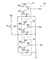
- FIG. 13 is a circuit diagram showing a configuration example in which a MOS transistor is used for the switch 61 (62, 63) of the connection switching device 260 of FIG.
- FIG. 13 shows one of the switches 61, 62, 63.
- the switches 61, 62, and 63 have the same configuration as each other and operate in the same manner.
- FIG. 14 is a diagram showing an example of an on / off state of the MOS transistor of the switch of FIG. 13 in tabular form.
- the switch 61 is a MOS transistor 616a (626a, 626a,) connected in series between the lead wire 61e (62e, 63e) and the output wire 332 (333,331).
- the switch 61 (62, 63) includes a MOS transistor 615a (625a, 635a) and a diode 615c (625c, 635c) connected in series between the lead wire 61e (62e, 63e) and the neutral point node 64.
- a MOS transistor 615b (625b, 635b) and a diode 615d (625d, 635d) connected in series between the lead wire 61e (62e, 63e) and the neutral point node 64.
- each MOS transistor 616a (626a, 636a), 616b (626b, 636b), 615a (625a, 635a), 615b (625b, 635b)
- the anode is connected to the diode and the cathode is the lead wire (or neutral point node or It has a parasitic diode connected to the output line).
- MOS transistors 616a, 626a, 636a are turned on, MOS transistors 616b, 626b, 636b are turned on, MOS transistors 615a, 625a, 635a are turned off, and MOS transistors 615b, 625b, 635b are turned off.
- the windings 71 to 73 can be connected by ⁇ .
- the MOS transistors 616a, 626a, 636a are turned off, the MOS transistors 616b, 626b, 636b are turned off, the MOS transistors 615a, 625a, 635a are turned on, and the MOS transistors 615b, 625b, 635b are turned on.
- the windings 71 to 73 can be Y-connected.
- the MOS transistor as a semiconductor switch is composed of a wide bandgap (WBG) semiconductor.
- the WBG semiconductor is, for example, a semiconductor containing silicon carbide (SiC), gallium nitride (GaN), gallium oxide (Ga2O3), and diamond as constituent materials.
- SiC silicon carbide
- GaN gallium nitride
- Ga2O3 gallium oxide
- diamond diamond
- connection switching device 260 made of a semiconductor, the normally closed switch 615, 625, 635 and the normally open switch 616, 626, 636 are switched within the power supply stop period Ps after the current control period Pc shown in FIG.
- the connection state can be switched while suppressing noise and vibration.
- connection switching device 260 when a mechanical relay is used for the connection switching device 260, failures such as contact welding can be prevented, and a highly reliable electric motor drive device can be obtained.
- connection switching device 260 when a semiconductor switch is used for the connection switching device 260, a failure due to heat generation of the semiconductor switch can be prevented, and a highly reliable electric motor drive device can be obtained.
- connection switching device 260 is configured with inexpensive parts, the failure occurrence rate can be reduced and the life of the device can be extended, so that the product cost can be extended. Can be reduced.
- the electric motor drive device of the second embodiment is the same as the electric motor drive device 2 of the first embodiment.
- Embodiment 3 Embodiment 3.
- an electric motor drive device to which the present invention is applied is connected to an electric motor 7 capable of switching windings 71 to 73 between Y connection and delta connection.
- an electric motor drive device to which the present invention is applied is connected to an electric motor 7a capable of switching the number of turns of each of the windings 71 to 73.
- the windings 71 to 73 of each phase are composed of two or more winding portions.
- the stator windings 71, 72, 73 are provided by the connection switching device 360 so that both ends of each of the two or more winding portions constituting the windings 71 to 73 of each phase can be connected to the outside of the motor 7a. (In the third embodiment, the number of turns of the winding) is switched. Further, the connection switching device to which the present invention is applied can also be applied to an electric motor capable of switching the winding portion to either parallel connection or series connection.
- the windings of each phase are composed of two winding portions, and both ends of the winding portions can be connected to the outside of the motor 7a, and the connection switching device 360 is shown.
- the configuration for switching the connection status is shown with.
- the U-phase winding 71 is composed of two winding portions 711 and 712
- the V-phase winding 72 is composed of two winding portions 721 and 722
- the W-phase winding 73 is composed of two winding portions 721 and 712. It is composed of two winding portions 731 and 732.
- the first end of the winding portion 711,721,731 is connected to the output lines 331, 332, 333 of the inverter 30 via the external terminals 71c, 72c, 73c, respectively.
- the second ends of the winding portions 711, 721 and 731 are connected to the common contacts of the changeover switches 617, 627 and 627 via the external terminals 71 g, 72 g and 73 g, respectively.
- the first end of the winding portion 712,722,732 is connected to the common contact of the changeover switches 618, 628, 638 via the external terminals 71h, 72h, 73h, respectively.
- the second ends of the winding portions 712, 722 and 732 are connected to the neutral point node 64 via the external terminals 71d, 72d and 73d, respectively.
- the normally closed contacts of the changeover switches 617, 627 and 637 are connected to the normally closed contacts of the changeover switches 618, 628 and 638, respectively.
- the normally open contacts of the changeover switches 617, 627, 637 are connected to the neutral point node 64.
- the normally open contacts of the changeover switches 618, 628, 638 are connected to the output lines 331, 332, 333 of the inverter 30.
- connection changeover device 360 is configured by the changeover switches 617, 627, 637, 618, 628, and 638.
- connection switching device 360 Even when such a connection switching device 360 is used, the switching operation of the switching device of the connection switching device 360 is performed during the current control period Pc in the same manner as that shown in the first and second embodiments. It can protect mechanical relays or semiconductor switches.
- a combination of the normally closed switch and the normally opened switch can be used instead of the changeover switch. Further, the normally closed switch and the normally opened switch can be used as a semiconductor switch.
- the electric motor drive device of an electric motor having a configuration in which an intermediate tap is provided in the winding in a Y connection or ⁇ connection and a part of the winding is short-circuited by a switching means to change the voltage required for driving.
- the present invention can be applied.
- the present invention can be applied as long as the electric motor can switch the connection state of the windings and the counter electromotive voltage can be switched by switching the connection state.
- the electric motor drive device of the third embodiment is the same as the electric motor drive device of the first or second embodiment.
- Electric motor drive device 4 AC power supply, 7, 7a electric motor, 8 reactor, 10 rectifier circuit, 20 capacitor, 30 inverter, 60, 260, 360 connection switching device, 61-63 switching device, 71-73 winding, 80 control Power generation circuit, 85 bus current detection means, 100 control device, 102 operation control unit, 110 inverter control unit, 900, 900a, 900b refrigeration cycle device, 902 four-way valve, 904 compressor, 906 heat exchanger, 908 expansion valve, 910 Heat exchanger.
Abstract
This electric motor drive device (2) has: a connection switching device (60) having switches (61-63) and switching the connection states of the windings (71-73) of an electric motor (7) by performing switching operation of the switches during the rotating operation of the electric motor; an inverter (30) which applies AC voltages to the windings via the switches and to which reverse electromotive forces are applied from the windings of the electric motor during the rotating operation via the switches; and a control device (100) for controlling the rotating operation of the electric motor by controlling the inverter and causing the connection switching device to switch the connection states. The electric motor drive device is equipped with: a first step having a current control period (Pc) in which the first effective values of the AC current flowing through the windings are made closer to zero than the second effective values of the AC currents flowing through the windings before the switching operation of the switches; and a second step being the step after the first step and having a power supply stop period (Ps) in which the AC voltages output by the inverter are stopped. The switching operation of the switches is performed during the period of the second step.
Description
本発明は、電動機駆動装置、それを備えた冷凍サイクル装置、並びに、この冷凍サイクル装置を備えた空気調和機、給湯機、及び冷蔵庫に関する。
The present invention relates to an electric motor drive device, a refrigeration cycle device including the electric motor drive device, and an air conditioner, a water heater, and a refrigerator equipped with the refrigeration cycle device.
従来、駆動輪と、駆動輪に駆動力を伝えるように接続され、かつ切り替え可能な巻線を有するモータと、モータの出力を指示する入力部と、入力部からの指示に基づいて制御信号を出力する制御部と、制御部からの制御信号に基づいてそのデューティー比が調整されモータに出力電圧を供給するインバータと、巻線を切り替える巻線切替部と、巻線を流れるモータ電流を検出する電流検出部と、モータの位相を検出する位相検出部とを備えた鞍乗型車両がある。この鞍乗型車両の制御部は、巻線の切り替え条件が成立したか否かを判断する切替判断部と、巻線の切り替え条件が成立したときデューティー比調整期間に入り、入力部からの指示に係わらずモータ電流が0になるように、電流検出部によって検出されたモータ電流と位相検出部によって検出されたモータの位相とに基づいてインバータのデューティー比を調整する調整部と、調整部によるデューティー比調整期間中に巻線切替部に対して巻線の切り替えを指示する切替指示部とを含む(例えば、特許文献1参照)。
Conventionally, a drive wheel, a motor connected so as to transmit a driving force to the drive wheel and having a switchable winding, an input unit for instructing the output of the motor, and a control signal based on an instruction from the input unit. The output control unit, the inverter whose duty ratio is adjusted based on the control signal from the control unit to supply the output voltage to the motor, the winding switching unit that switches the winding, and the motor current that flows through the winding are detected. There is a saddle-type vehicle including a current detection unit and a phase detection unit that detects the phase of the motor. The control unit of this saddle-type vehicle has a switching determination unit that determines whether or not the winding switching condition is satisfied, and a duty ratio adjustment period when the winding switching condition is satisfied, and an instruction from the input unit. The adjustment unit adjusts the duty ratio of the inverter based on the motor current detected by the current detection unit and the phase of the motor detected by the phase detection unit so that the motor current becomes 0 regardless of the above. It includes a switching instruction unit that instructs the winding switching unit to switch the winding during the duty ratio adjustment period (see, for example, Patent Document 1).
特許文献1(例えば、図2)に記載された技術では、モータ電流を0に制御する場合に、モータの逆起電圧とインバータの出力電圧とを一致させることが必要となる。つまり、巻線を切り替える際にはインバータによる通電を継続していることとなる。巻線を切り替えるスイッチ(42a~42c)において機械式のリレーを用いた場合には、スイッチ(42a)の端子(TU2とTU3)間の導通状態から、端子(TU3)をOFF状態とし、端子(TU5)をON状態、つまり端子(TU2とTU5)間を導通状態にするよう操作した場合に、モータ電流を完全に0に制御することは現実的に不可能であり、端子(TU3)から引きはがす際にアーク放電が発生し、またインバータが通電状態であるため端子(TU2とTU5)間に電位差が発生しているため、端子(TU5)の接する直前に電位差に起因したアーク放電が発生する。このような2つのアーク放電が同時に発生すると端子(TU2)が端子(TU3とTU5)の両方に導通状態となる瞬間が発生する。その場合巻線(RU)と端子(TU3、TU5)を介した閉ループが発生し、巻線(RU)が有する誘起電圧により短絡状態が発生してしまい、メカ式リレーが溶着故障する恐れがある。
In the technique described in Patent Document 1 (for example, FIG. 2), when the motor current is controlled to 0, it is necessary to match the counter electromotive voltage of the motor with the output voltage of the inverter. That is, when the winding is switched, the power supply by the inverter is continued. When a mechanical relay is used in the switch (42a to 42c) for switching the winding, the terminal (TU3) is turned off from the conduction state between the terminals (TU2 and TU3) of the switch (42a), and the terminal (TU3) is turned off. When the TU5) is turned on, that is, when the terminals (TU2 and TU5) are operated to be in a conductive state, it is practically impossible to completely control the motor current to 0, and the motor current is pulled from the terminal (TU3). An arc discharge occurs when the terminal (TU5) is peeled off, and a potential difference is generated between the terminals (TU2 and TU5) because the inverter is energized. Therefore, an arc discharge due to the potential difference occurs immediately before the terminals (TU5) come into contact with each other. .. When such two arc discharges occur at the same time, a moment occurs in which the terminal (TU2) becomes conductive on both the terminals (TU3 and TU5). In that case, a closed loop is generated via the winding (RU) and the terminals (TU3, TU5), a short circuit state occurs due to the induced voltage of the winding (RU), and the mechanical relay may be welded and failed. ..
本発明は、上記に鑑みてなされたものであって、電動機の巻線の接続状態を切替える切替器の切替え動作を電動機の回転動作を停止させずに行うことができ、且つ接続状態の切替えに起因する故障が生じにくい電動機駆動装置及びそれを備えた装置を提供することを目的とする。
The present invention has been made in view of the above, and the switching operation of the switch for switching the connection state of the windings of the electric motor can be performed without stopping the rotational operation of the electric motor, and the connection state can be switched. An object of the present invention is to provide an electric motor drive device which is less likely to cause a failure due to the failure and a device provided with the electric motor drive device.
本発明に係る電動機駆動装置は、切替器を有し、電動機の回転動作中に前記切替器の切替え動作を行うことによって前記電動機の巻線の接続状態を切替える接続切替装置と、前記切替器を介して前記巻線に交流電圧を印加するとともに、前記切替器を介して回転動作中の前記電動機の前記巻線から逆起電圧が印加されるインバータと、前記インバータを制御することによって前記電動機の回転動作を制御し、前記接続切替装置に前記接続状態の切替えを実行させる制御装置と、を有し、前記巻線に流れる交流電流の第1の実効値が前記切替器の切替え動作の前において前記巻線に流れる交流電流の第2の実効値よりゼロに近づける電流制御期間を有する第1の段階と、前記第1の段階の後の段階であり、前記インバータが出力する交流電圧を停止させる給電停止期間を有する第2の段階と、を備え、前記第2の段階の期間中に、前記切替器の切替え動作を実行させる。
The electric motor drive device according to the present invention includes a connection switching device that has a switching device and switches the connection state of the windings of the electric motor by performing the switching operation of the switching device during the rotation operation of the electric motor, and the switching device. An AC voltage is applied to the winding through the winding, and a countercurrent voltage is applied from the winding of the electric motor in rotation operation via the switch, and the electric motor is controlled by controlling the inverter. It has a control device that controls the rotation operation and causes the connection switching device to switch the connection state, and the first effective value of the alternating current flowing through the winding is before the switching operation of the switching device. The first stage having a current control period closer to zero than the second effective value of the AC current flowing through the winding, and the stage after the first stage, the AC voltage output by the inverter is stopped. A second stage having a power supply stop period is provided, and the switching operation of the switch is executed during the period of the second stage.
本発明によれば、巻線に流れる交流電流の実効値をゼロに近づけるように制御された電流制御期間ののちに、インバータの通電を停止する期間を設け、その期間内に接続切替装置の切替器の切替え動作を行うので、接続切替装置の故障は発生しにくく、電動機駆動装置の寿命を長くすることができる。
According to the present invention, after a current control period in which the effective value of the alternating current flowing in the winding is controlled to approach zero, a period for stopping the energization of the inverter is provided, and the connection switching device is switched within that period. Since the device is switched, the connection switching device is less likely to fail, and the life of the motor drive device can be extended.
また、本発明によれば、電動機の回転動作が停止していない電流制御期間中に、巻線の接続状態を切替える。このため、巻線の接続状態の切替えのために、電動機の回転動作を一時停止させ、その後電動機を再始動させる動作が不要である。
Further, according to the present invention, the connection state of the winding is switched during the current control period in which the rotational operation of the electric motor is not stopped. Therefore, it is not necessary to suspend the rotational operation of the motor and then restart the motor in order to switch the connection state of the windings.
以下に、添付図面を参照して、本発明の実施の形態に係る電動機駆動装置、それを備えた冷凍サイクル適用機器である冷凍サイクル装置、並びに、この冷凍サイクル装置を備えた空気調和機、給湯機、及び冷蔵庫について説明する。なお、以下に示す実施の形態は例に過ぎず、電動機駆動装置及びそれを備えた各装置は、本発明の範囲内で種々の変更が可能である。なお、以下の説明において、同じ符号が付された構成要素は、同じ又は同様の機能を持つ。
Hereinafter, with reference to the accompanying drawings, an electric motor drive device according to an embodiment of the present invention, a refrigerating cycle device including the refrigerating cycle applicable device, an air conditioner equipped with the refrigerating cycle device, and a hot water supply. The machine and the refrigerator will be described. The embodiments shown below are merely examples, and the electric motor drive device and each device provided with the electric motor drive device can be modified in various ways within the scope of the present invention. In the following description, the components with the same reference numerals have the same or similar functions.
図1は、実施の形態の空気調和機(冷凍サイクル装置900を含む)の構成例を示す概略図である。図1に示されるように、冷凍サイクル装置900は、四方弁902の切替え動作により暖房運転又は冷房運転をすることができる。
FIG. 1 is a schematic view showing a configuration example of an air conditioner (including a refrigeration cycle device 900) of the embodiment. As shown in FIG. 1, the refrigeration cycle device 900 can perform a heating operation or a cooling operation by the switching operation of the four-way valve 902.
暖房運転時には、実線矢印で示されるように、冷媒が圧縮機904で加圧されて送り出され、四方弁902、室内の熱交換器906、膨張弁908、室外の熱交換器910及び四方弁902を通って圧縮機904に戻る。冷房運転時には、破線矢印で示されるように、冷媒が圧縮機904で加圧されて送り出され、四方弁902、室外の熱交換器910、膨張弁908、室内の熱交換器906及び四方弁902を通って圧縮機904に戻る。
During the heating operation, as shown by the solid line arrow, the refrigerant is pressurized by the compressor 904 and sent out, and the four-way valve 902, the indoor heat exchanger 906, the expansion valve 908, the outdoor heat exchanger 910 and the four-way valve 902. It returns to the compressor 904 through. During cooling operation, as shown by the broken line arrow, the refrigerant is pressurized by the compressor 904 and sent out, and the four-way valve 902, the outdoor heat exchanger 910, the expansion valve 908, the indoor heat exchanger 906 and the four-way valve 902. It returns to the compressor 904 through.
暖房運転時には、熱交換器906が凝縮器として作用して熱放出を行い(室内を暖房し)、熱交換器910が蒸発器として作用して熱吸収を行う。冷房運転時には、熱交換器910が凝縮器として作用して熱放出を行い、熱交換器906が蒸発器として作用し、熱吸収を行う(室内を冷房する)。膨張弁908は、冷媒を減圧して膨張させる。圧縮機904は、電動機駆動装置2によって可変速制御される電動機7によって駆動される。
During the heating operation, the heat exchanger 906 acts as a condenser to release heat (heats the room), and the heat exchanger 910 acts as an evaporator to absorb heat. During the cooling operation, the heat exchanger 910 acts as a condenser to release heat, and the heat exchanger 906 acts as an evaporator to absorb heat (cool the room). The expansion valve 908 depressurizes the refrigerant and expands it. The compressor 904 is driven by an electric motor 7 whose speed is variably controlled by the electric motor drive device 2.
図2は、実施の形態のヒートポンプ式給湯器(冷凍サイクル装置900aを含む)の構成例を示す概略図である。図2に示されるように、冷凍サイクル装置900aでは、熱交換器906が凝縮器として作用して熱放出を行い(水を温め)、熱交換器910が蒸発器として作用して熱吸収を行う。圧縮機904は、電動機駆動装置2によって可変速制御される電動機7によって駆動される。
FIG. 2 is a schematic view showing a configuration example of the heat pump type water heater (including the refrigeration cycle device 900a) of the embodiment. As shown in FIG. 2, in the refrigeration cycle apparatus 900a, the heat exchanger 906 acts as a condenser to release heat (warms water), and the heat exchanger 910 acts as an evaporator to absorb heat. .. The compressor 904 is driven by an electric motor 7 whose speed is variably controlled by the electric motor drive device 2.
図3は、実施の形態の冷蔵庫(冷凍サイクル装置900bを含む)の構成例を示す概略図である。図3に示されるように、冷凍サイクル装置900bでは、熱交換器910が凝縮器として作用して熱放出を行い、熱交換器906が蒸発器として作用し、熱吸収を行う(冷蔵庫内を冷却する)。圧縮機904は、電動機駆動装置2によって可変速制御される電動機7によって駆動される。
FIG. 3 is a schematic view showing a configuration example of the refrigerator (including the refrigerating cycle device 900b) of the embodiment. As shown in FIG. 3, in the refrigeration cycle apparatus 900b, the heat exchanger 910 acts as a condenser to release heat, and the heat exchanger 906 acts as an evaporator to absorb heat (cooling the inside of the refrigerator). To do). The compressor 904 is driven by an electric motor 7 whose speed is variably controlled by the electric motor drive device 2.
《1》実施の形態1.
《1-1》実施の形態1の概要
図4は、本発明の実施の形態1の電動機駆動装置2を、電動機7及び交流電源4とともに示す概略配線図である。電動機駆動装置2は、電動機7を駆動するためのものである。図4に示されるように、電動機駆動装置2は、インバータ30と、接続切替装置60と、制御装置100とを備える。また、電動機駆動装置2は、交流電源入力端子2a,2bと、リアクトル8と、整流回路10と、コンデンサ20と、制御電源生成回路80と、母線電流検出手段85と、電気量検出部90とを備えてもよい。 << 1 >>Embodiment 1.
<< 1-1 >> Outline of the first embodiment FIG. 4 is a schematic wiring diagram showing the electricmotor drive device 2 of the first embodiment of the present invention together with the electric motor 7 and the AC power supply 4. The electric motor drive device 2 is for driving the electric motor 7. As shown in FIG. 4, the electric motor driving device 2 includes an inverter 30, a connection switching device 60, and a control device 100. Further, the electric motor drive device 2 includes AC power input terminals 2a and 2b, a reactor 8, a rectifier circuit 10, a capacitor 20, a control power generation circuit 80, a bus current detecting means 85, and an electric amount detecting unit 90. May be provided.
《1-1》実施の形態1の概要
図4は、本発明の実施の形態1の電動機駆動装置2を、電動機7及び交流電源4とともに示す概略配線図である。電動機駆動装置2は、電動機7を駆動するためのものである。図4に示されるように、電動機駆動装置2は、インバータ30と、接続切替装置60と、制御装置100とを備える。また、電動機駆動装置2は、交流電源入力端子2a,2bと、リアクトル8と、整流回路10と、コンデンサ20と、制御電源生成回路80と、母線電流検出手段85と、電気量検出部90とを備えてもよい。 << 1 >>
<< 1-1 >> Outline of the first embodiment FIG. 4 is a schematic wiring diagram showing the electric
接続切替装置60は、切替器(スイッチ回路)61~63を有し、電動機7の回転動作中に切替器61~63の切替え動作を行うことによって電動機7の巻線71~73の接続状態(結線状態)を切替える。インバータ30は、切替器61~63を介して巻線71~73に交流電圧を印加するとともに、切替器61~63を介して回転動作中の電動機7の巻線71~73から逆起電圧が印加される。
The connection switching device 60 has switches (switch circuits) 61 to 63, and by performing the switching operation of the switching devices 61 to 63 during the rotation operation of the electric motor 7, the connection state of the windings 71 to 73 of the electric motor 7 ( (Connection state) is switched. The inverter 30 applies an AC voltage to the windings 71 to 73 via the switches 61 to 63, and receives a counter electromotive voltage from the windings 71 to 73 of the electric motor 7 rotating via the switches 61 to 63. It is applied.
制御装置100は、インバータ30を制御することによって電動機7の回転動作を制御する。また、制御装置100は、接続切替装置60に巻線の接続状態の切替えを実行させる。実施の形態1においては、制御装置100は、巻線71~73に流れる交流電流の値(第1の実効値)が切替器61~63の切替え動作の前において巻線に流れる交流電流の値(第2の実効値)よりゼロに近づけられている電流制御期間Pc(「ゼロ電流制御期間」とも言う)内に、切替器61~63の切替え動作を実行させる。
The control device 100 controls the rotational operation of the electric motor 7 by controlling the inverter 30. Further, the control device 100 causes the connection switching device 60 to switch the connection state of the windings. In the first embodiment, in the control device 100, the value of the alternating current flowing through the windings 71 to 73 (the first effective value) is the value of the alternating current flowing through the windings before the switching operation of the switches 61 to 63. The switching operation of the switches 61 to 63 is executed within the current control period Pc (also referred to as “zero current control period”) which is closer to zero than (second effective value).
なお、本出願において、巻線の接続状態は、巻線の結線状態(例えば、Y結線とΔ結線)と、巻線の巻数との両方を含む。巻線の巻数の切替えについては、実施の形態3で説明する。また、切替器61~63をメカリレーで構成した場合には、電流制御期間Pcは、数百ミリ秒以下に設定できる。切替器61~63を半導体スイッチで構成した場合には、電流制御期間Pcは、数ミリ秒以下に設定できる。また、電動機7を空気調和機、ヒートポンプ式給湯器、冷蔵庫などの冷凍サイクル装置の圧縮機に使用する場合には、電流制御期間Pcは、数m秒から1秒までの範囲内で設定できる。
In the present application, the connection state of the winding includes both the connection state of the winding (for example, Y connection and Δ connection) and the number of turns of the winding. The switching of the number of turns of the winding will be described in the third embodiment. Further, when the switches 61 to 63 are configured by the mechanical relay, the current control period Pc can be set to several hundred milliseconds or less. When the switches 61 to 63 are composed of semiconductor switches, the current control period Pc can be set to several milliseconds or less. Further, when the electric motor 7 is used as a compressor of a refrigerating cycle device such as an air conditioner, a heat pump type water heater, or a refrigerator, the current control period Pc can be set within a range of several msec to 1 second.
《1-2》実施の形態1の構成
制御装置100は、例えば、制御情報をソフトウェアプログラムとして記憶する記憶装置としてのメモリと、このプログラムを実行する情報処理装置としてのCPU(Central Processing Unit)とを備えたマイコン(マイクロコンピュータ)、又はDSP(Digital Signal Processor)等で構成される。また、制御装置100は、専用のハードウェア(例えば、処理回路)で構成されていてもよい。以下では、制御装置100がマイコンで構成されている場合を説明する。 << 1-2 >> Configuration of the first embodiment Thecontrol device 100 includes, for example, a memory as a storage device for storing control information as a software program, and a CPU (Central Processing Unit) as an information processing device for executing this program. It is composed of a microcomputer (microcomputer) equipped with a device, a DSP (Digital Signal Processor), or the like. Further, the control device 100 may be composed of dedicated hardware (for example, a processing circuit). Hereinafter, a case where the control device 100 is composed of a microcomputer will be described.
制御装置100は、例えば、制御情報をソフトウェアプログラムとして記憶する記憶装置としてのメモリと、このプログラムを実行する情報処理装置としてのCPU(Central Processing Unit)とを備えたマイコン(マイクロコンピュータ)、又はDSP(Digital Signal Processor)等で構成される。また、制御装置100は、専用のハードウェア(例えば、処理回路)で構成されていてもよい。以下では、制御装置100がマイコンで構成されている場合を説明する。 << 1-2 >> Configuration of the first embodiment The
交流電源入力端子2a,2bは、外部の交流電源4に接続される。交流電源入力端子2a,2bには、交流電源4から交流電圧が印加される。印加される電圧は、例えば、振幅(実効値)が100V又は200V等であり、周波数が50Hz又は60Hz等である。
The AC power input terminals 2a and 2b are connected to the external AC power supply 4. An AC voltage is applied from the AC power supply 4 to the AC power supply input terminals 2a and 2b. The applied voltage has, for example, an amplitude (effective value) of 100 V or 200 V or the like, and a frequency of 50 Hz or 60 Hz or the like.
整流回路10は、交流電源4から入力端子2a,2b及びリアクトル8を介して交流電力を受けて整流することで、直流電圧を生成する。整流回路10は、ダイオード等の整流素子11~14をブリッジ接続することで形成された全波整流回路である。
The rectifier circuit 10 generates a DC voltage by receiving AC power from the AC power supply 4 via the input terminals 2a and 2b and the reactor 8 and rectifying the rectifier. The rectifier circuit 10 is a full-wave rectifier circuit formed by bridging rectifier elements 11 to 14 such as diodes.
コンデンサ20は、整流回路10で生成された直流電圧を平滑化して、直流電圧V20を出力する。
The capacitor 20 smoothes the DC voltage generated by the rectifier circuit 10 and outputs the DC voltage V20.
図5は、図4のインバータ30の構成を示す図である。図5に示されるように、インバータ30は、インバータ主回路310と、駆動回路350とを有する。インバータ主回路310の入力端子は、コンデンサ20の電極に接続されている。整流回路10の出力、コンデンサ20の電極、及びインバータ主回路310の入力端子を結ぶ線を、直流母線と言う。
FIG. 5 is a diagram showing the configuration of the inverter 30 of FIG. As shown in FIG. 5, the inverter 30 has an inverter main circuit 310 and a drive circuit 350. The input terminal of the inverter main circuit 310 is connected to the electrode of the capacitor 20. The line connecting the output of the rectifier circuit 10, the electrode of the capacitor 20, and the input terminal of the inverter main circuit 310 is called a DC bus.
インバータ30は、制御装置100によって制御されて、インバータ主回路310の6つのアームのスイッチング素子311~316がオン、オフ動作する。このオン、オフ動作によって、インバータ30は、周波数可変で電圧可変の3相交流電流を生成し、この3相交流電流を電動機7に供給する。スイッチング素子311~316には、還流用の整流素子321~326がそれぞれ並列接続されている。
The inverter 30 is controlled by the control device 100, and the switching elements 311 to 316 of the six arms of the inverter main circuit 310 operate on and off. By this on / off operation, the inverter 30 generates a three-phase alternating current having a variable frequency and a variable voltage, and supplies the three-phase alternating current to the motor 7. Rectifying elements 321 to 326 for reflux are connected in parallel to the switching elements 311 to 316, respectively.
電動機7は、3相永久磁石同期電動機であり、固定子巻線(以下「巻線」とも言う)の端部が電動機7の外部に引き出されており、スター結線(Y結線)及びデルタ結線(Δ結線)のいずれかへの切替えが可能なものである。この切替えは、接続切替装置60により行われる。なお、Y結線を第1の結線という場合には、Δ結線が第2の結線であり、Δ結線を第1の結線という場合には、Y結線が第2の結線である。また、巻線の接続状態は、3種類以上であってもよい。
The motor 7 is a three-phase permanent magnet synchronous motor, and the end of the stator winding (hereinafter also referred to as “winding”) is pulled out to the outside of the motor 7, and star connection (Y connection) and delta connection (Y connection) and delta connection ( It is possible to switch to any of (Δ connection). This switching is performed by the connection switching device 60. When the Y connection is referred to as the first connection, the Δ connection is the second connection, and when the Δ connection is referred to as the first connection, the Y connection is the second connection. Further, the connection state of the winding may be three or more types.
図6は、電動機7の固定子巻線及び接続切替装置60をより詳細に示す配線図である。図6に示されるように、電動機7の、U相、V相、W相から成る3つの相の巻線71,72,73の第1の端部71a,72a,73aが、外部端子71c,72c,73cにそれぞれ接続されている。電動機7の、U相、V相、W相の巻線71,72,73の第2の端部71b,72b,73bが、外部端子71d,72d,73dにそれぞれ接続されている。このように、電動機7は、接続切替装置60との接続が可能となっている。また、外部端子71c,72c,73cには、インバータ30のU相、V相、W相の出力線331,332,333が接続されている。
FIG. 6 is a wiring diagram showing the stator winding and the connection switching device 60 of the electric motor 7 in more detail. As shown in FIG. 6, the first ends 71a, 72a, 73a of the three- phase windings 71, 72, 73 of the electric motor 7 composed of the U phase, the V phase, and the W phase are the external terminals 71c, It is connected to 72c and 73c, respectively. The second ends 71b, 72b, 73b of the U-phase, V-phase, and W- phase windings 71, 72, and 73 of the electric motor 7 are connected to the external terminals 71d, 72d, and 73d, respectively. In this way, the electric motor 7 can be connected to the connection switching device 60. Further, the U-phase, V-phase, and W-phase output lines of the inverter 30 are connected to the external terminals 71c, 72c, and 73c.
接続切替装置60は、図示の例では、切替器61~63で構成されている。切替器61,62,63としては、電磁的に接点が開閉する電磁接触器が用いられている。そのような電磁接触器は、リレー、コンタクターなどと呼ばれるものが含まれる。
In the illustrated example, the connection switching device 60 is composed of switching devices 61 to 63. As the switching devices 61, 62, 63, an electromagnetic contactor whose contacts are opened and closed electromagnetically is used. Such magnetic contactors include what are called relays, contactors and the like.
図7は、切替器61~63の構成例を示す配線図である。切替器61~63は、例えば、図7に示されるように構成されており、励磁コイル611,621,631に電流が流されているときと、電流が流されていないときとで、異なる結線状態を取る。励磁コイル611,621,631は、半導体スイッチ604を介して、切替電源電圧V60を受けるように接続される。半導体スイッチ604の開閉は、制御装置100から出力される切替制御信号Scにより制御される。なお、制御装置100に含まれるマイコンからの電流供給が十分確保されている場合には、マイコンから直接励磁コイルに電流を流すように動作してもよい。
FIG. 7 is a wiring diagram showing a configuration example of the switches 61 to 63. The switches 61 to 63 are configured as shown in FIG. 7, for example, and have different connections depending on whether a current is flowing through the exciting coils 611, 621, 631 and when no current is flowing. Take the state. The exciting coils 611, 621 and 631 are connected via the semiconductor switch 604 so as to receive the switching power supply voltage V60. The opening and closing of the semiconductor switch 604 is controlled by the switching control signal Sc output from the control device 100. If the current supply from the microcomputer included in the control device 100 is sufficiently secured, the operation may be performed so that the current flows directly from the microcomputer to the exciting coil.
切替器61の共通接点61cは、リード線61eを介して外部端子71dに接続されている。常閉接点61bは、中性点ノード64に接続され、常開接点61aは、インバータ30のV相の出力線332に接続されている。
The common contact 61c of the switch 61 is connected to the external terminal 71d via the lead wire 61e. The normally closed contact 61b is connected to the neutral point node 64, and the normally open contact 61a is connected to the V-phase output line 332 of the inverter 30.
切替器62の共通接点62cは、リード線62eを介して外部端子72dに接続されている。常閉接点62bは、中性点ノード64に接続され、常開接点62aは、インバータ30のW相の出力線333に接続されている。
The common contact 62c of the switch 62 is connected to the external terminal 72d via the lead wire 62e. The normally closed contact 62b is connected to the neutral point node 64, and the normally open contact 62a is connected to the W phase output line 333 of the inverter 30.
切替器63の共通接点63cは、リード線63eを介して外部端子73dに接続されている。常閉接点63bは、中性点ノード64に接続され、常開接点63aは、インバータ30のU相の出力線331に接続されている。
The common contact 63c of the switch 63 is connected to the external terminal 73d via the lead wire 63e. The normally closed contact 63b is connected to the neutral point node 64, and the normally open contact 63a is connected to the U-phase output line 331 of the inverter 30.
励磁コイル611,621,631に電流が流れていないときは、切替器61,62,63が、図7に示されるように、常閉接点側に切替わった状態、即ち、共通接点61c,62c,63cが常閉接点61b,62b,63bに接続された状態にある。この状態では、電動機7は、Y結線状態にある。
When no current is flowing through the exciting coils 611, 621, 631, the switches 61, 62, 63 are switched to the normally closed contact side, that is, the common contacts 61c, 62c, as shown in FIG. , 63c are connected to the normally closed contacts 61b, 62b, 63b. In this state, the electric motor 7 is in the Y connection state.
励磁コイル611,621,631に電流が流れているときは、切替器61,62,63が図示とは逆に、常開接点側に切替わった状態、即ち、共通接点61c,62c,63cが常開接点61a,62a,63aに接続された状態にある。この状態では、電動機7は、Δ結線状態にある。
When a current is flowing through the exciting coils 611, 621, 631, the switches 61, 62, 63 are switched to the normally open contact side, that is, the common contacts 61c, 62c, 63c are in the opposite direction of the drawing. It is in a state of being connected to the normally open contacts 61a, 62a, 63a. In this state, the electric motor 7 is in the Δ connection state.
ここで、電動機7としてY結線及びΔ結線のいずれかへの切替えが可能なものを用いることの利点について図8(a)及び(b)を用いて説明する。図8(a)は、Y結線としたときの巻線の結線状態、図8(b)は、Δ結線としたときの巻線の結線状態をそれぞれ概念的に示す。
Here, the advantages of using an electric motor 7 that can be switched to either a Y connection or a Δ connection will be described with reference to FIGS. 8 (a) and 8 (b). FIG. 8A conceptually shows the connection state of the winding when the Y connection is made, and FIG. 8B conceptually shows the connection state of the winding when the Δ connection is made.
Y結線時の線間電圧をVY、巻線に流れ込む電流をIYとし、Δ結線時の線間電圧をVΔ、巻線に流れ込む電流をIΔとし、各相の巻線に掛かる電圧が互いに等しいとすると、以下の式(1)及び(2)の関係がある。
VΔ=VY/√3 (1)
IΔ=√3×IY (2) The line voltage at the time of Y connection is V Y , the current flowing into the winding is I Y , the line voltage at the time of Δ connection is V Δ , the current flowing into the winding is I Δ, and the voltage applied to the winding of each phase. Assuming that are equal to each other, there is a relationship of the following equations (1) and (2).
V Δ = V Y / √3 (1)
I Δ = √3 × I Y (2)
Y結線時の電圧VY及び電流IYと、Δ結線時の電圧VΔ及び電流IΔとが式(1)及び(2)の関係を有するとき、Y結線時とΔ結線時とで電動機に供給される電力が互いに等しい。つまり、電動機に供給される電力が互いに等しいとき、Δ結線の方が電流は大きく、駆動に必要な電圧が低い。
When the voltage V Y and current I Y at the time of Y connection and the voltage V Δ and current I Δ at the time of Δ connection have the relationship of the equations (1) and (2), the electric power is connected at the time of Y connection and the time of Δ connection. The power supplied to is equal to each other. That is, when the electric power supplied to the electric motor is equal to each other, the current is larger in the Δ connection and the voltage required for driving is lower.
以上の性質を利用し、負荷条件等に応じて結線状態を選択することが考えられる。例えば、低負荷時には、Y結線で低速運転し、高負荷時には、Δ結線で高速運転することが考えられる。このようにすることで、低負荷時の効率を向上させ、高負荷時の高出力化も可能となる。
It is conceivable to select the connection state according to the load conditions, etc. by utilizing the above properties. For example, when the load is low, the Y connection may be used for low-speed operation, and when the load is high, the Δ connection may be used for high-speed operation. By doing so, the efficiency at low load can be improved, and the output at high load can be increased.
以下に、この点について、空気調和機の圧縮機を駆動する電動機の場合について、さらに詳しく述べる。空気調和機の圧縮機駆動用の電動機7としては、省エネルギー化の要求に応えるため、回転子に永久磁石を備えた同期電動機が広く用いられている。また、近年の空気調和機においては、室温と設定温度との差が大きいときは、電動機7を高速で回転させる高速運転によって室温を設定温度に早く近づけ、室温が設定温度に近いときは、電動機7を低速で回転させる低速運転によって室温を維持するようにしている。このように制御する場合、全運転時間に対する低速運転の時間の占める割合が大きい。
Below, this point will be described in more detail in the case of the electric motor that drives the compressor of the air conditioner. As the electric motor 7 for driving the compressor of the air conditioner, a synchronous motor having a permanent magnet in the rotor is widely used in order to meet the demand for energy saving. Further, in recent air conditioners, when the difference between the room temperature and the set temperature is large, the room temperature is quickly brought closer to the set temperature by high-speed operation of rotating the electric motor 7 at a high speed, and when the room temperature is close to the set temperature, the electric motor is used. Room temperature is maintained by low-speed operation in which 7 is rotated at a low speed. When controlled in this way, the ratio of the low-speed operation time to the total operation time is large.
同期電動機を用いた場合、回転数が上がると逆起電力が増加し、駆動に必要な電圧値が増加する。この逆起電力は、上記のようにY結線の方がΔ結線に比べて高い。
When a synchronous motor is used, the counter electromotive force increases as the rotation speed increases, and the voltage value required for driving increases. This counter electromotive force is higher in the Y connection than in the Δ connection as described above.
高速での逆起電力を抑制するために、永久磁石の磁力を小さくしたり、固定子巻線の巻き数を減らしたりすることが考えられる。しかし、そのようにすると、同一出力トルクを得るための電流が増加するため、電動機7及びインバータ30に流れる電流が増加し、効率が低下する。
In order to suppress the back electromotive force at high speed, it is conceivable to reduce the magnetic force of the permanent magnet or reduce the number of turns of the stator winding. However, if this is done, the current for obtaining the same output torque increases, so that the current flowing through the motor 7 and the inverter 30 increases, and the efficiency decreases.
そこで、回転数に応じて結線状態を切替えることが考えられる。例えば、高速での運転が必要な場合には、Δ結線状態とする。こうすることで、駆動に必要な電圧を(Y結線に比べ)1/√3にすることができる。このため、巻線の巻数を減らす必要もなく、また弱め磁束制御を用いる必要もなくなる。
Therefore, it is conceivable to switch the connection state according to the number of rotations. For example, when high-speed operation is required, the Δ connection state is set. By doing so, the voltage required for driving can be reduced to 1 / √3 (compared to the Y connection). Therefore, it is not necessary to reduce the number of turns of the winding, and it is not necessary to use the weakening magnetic flux control.
一方、低速回転では、Y結線状態とすることでΔ結線に比べて電流値を1/√3にできる。さらに、巻線をY結線状態で低速での駆動に適したように設計することが可能となり、Y結線を速度範囲の全域にわたり使用する場合に比べて、電流値を低減することが可能となる。この結果、インバータ30の損失を低減することができ、効率を高めることが可能となる。
On the other hand, in low-speed rotation, the current value can be reduced to 1 / √3 compared to the Δ connection by setting the Y connection state. Further, the winding can be designed to be suitable for driving at a low speed in the Y connection state, and the current value can be reduced as compared with the case where the Y connection is used over the entire speed range. .. As a result, the loss of the inverter 30 can be reduced and the efficiency can be improved.
以上説明したように、負荷条件に応じて結線状態を切替えることには意義があり、接続切替装置60が設けられるのは、このような切替えを可能にするためである。
As described above, it is significant to switch the connection state according to the load condition, and the connection switching device 60 is provided in order to enable such switching.
図4に示される母線電流検出手段85は、母線電流、即ち、インバータ30に入力する直流電流Idcを検出する。母線電流検出手段85は、直流母線に挿入されたシャント抵抗を含み、検出結果を示すアナログ信号を制御装置100に供給する。この信号(検出信号)は、制御装置100で図示しないA/D(Analog to Digital)変換部によりデジタル信号に変換されて制御装置100の内部での処理に用いられる。
The bus current detecting means 85 shown in FIG. 4 detects the bus current, that is, the DC current Idc input to the inverter 30. The bus current detecting means 85 includes a shunt resistor inserted in the DC bus and supplies an analog signal indicating the detection result to the control device 100. This signal (detection signal) is converted into a digital signal by an A / D (Analog to Digital) converter (not shown) in the control device 100 and used for processing inside the control device 100.
制御装置100は、上記のように、接続切替装置60による結線状態の切替えを制御するとともに、インバータ30の動作を制御する。インバータ30の制御のため、制御装置100は、PWM(Pulse Width Modulation)信号Sm1~Sm6を生成して、インバータ30に供給する。
As described above, the control device 100 controls the switching of the connection state by the connection switching device 60 and also controls the operation of the inverter 30. To control the inverter 30, the control device 100 generates PWM (Pulse Width Modulation) signals Sm1 to Sm6 and supplies them to the inverter 30.
図5に示されるように、インバータ30は、インバータ主回路310のほかに、駆動回路350を備えており、駆動回路350がPWM信号に基づいて駆動信号Sr1~Sr6を生成する。駆動回路350は、駆動信号Sr1~Sr6によりスイッチング素子311~316のオン、オフを制御し、これにより、周波数可変で電圧可変の3相交流電圧が電動機7に印加される。
As shown in FIG. 5, the inverter 30 includes a drive circuit 350 in addition to the inverter main circuit 310, and the drive circuit 350 generates drive signals Sr1 to Sr6 based on the PWM signal. The drive circuit 350 controls the switching elements 311 to 316 to be turned on and off by the drive signals Sr1 to Sr6, whereby a three-phase AC voltage having a variable frequency and a variable voltage is applied to the motor 7.
PWM信号Sm1~Sm6が論理回路の信号レベルの大きさ(0~5V)のものであるのに対し、駆動信号Sr1~Sr6は、スイッチング素子311~316を制御するのに必要な電圧レベル、例えば、+15Vから-15Vまでの大きさを持つ信号である。また、PWM信号Sm1~Sm6が、制御装置100の接地電位を基準電位とするものであるのに対し、駆動信号Sr1~Sr6は、それぞれ対応するスイッチング素子の負側の端子(エミッタ端子)の電位を基準電位とするものである。
While the PWM signals Sm1 to Sm6 are of the signal level magnitude (0 to 5V) of the logic circuit, the drive signals Sr1 to Sr6 are voltage levels required to control the switching elements 311 to 316, for example. , A signal having a magnitude from + 15V to -15V. Further, the PWM signals Sm1 to Sm6 use the ground potential of the control device 100 as a reference potential, whereas the drive signals Sr1 to Sr6 are the potentials of the negative terminals (emitter terminals) of the corresponding switching elements. Is the reference potential.
図9は、図4の制御装置100の一例を示す機能ブロック図である。図9に示されるように、制御装置100は、運転制御部102及びインバータ制御部110を有する。
FIG. 9 is a functional block diagram showing an example of the control device 100 of FIG. As shown in FIG. 9, the control device 100 includes an operation control unit 102 and an inverter control unit 110.
運転制御部102は、電気量検出部90から提供される指令信号Qeに基づいて指示信号を出力する。電気量検出部90は、図示しない温度センサで検出された室温(空調対象空間の温度)を示す電気信号の電気量に基づく指令信号、並びに、図示しない操作部、例えば、リモコンからの指示情報を示す指令信号を受け、空気調和機の各部の動作を制御する。操作部からの指示には、設定温度を示す情報、運転モードの選択、運転開始及び終了の指示等が含まれる。
The operation control unit 102 outputs an instruction signal based on the command signal Qe provided by the electric energy detection unit 90. The electric amount detection unit 90 transmits a command signal based on the electric amount of an electric signal indicating the room temperature (temperature of the air-conditioned space) detected by a temperature sensor (not shown), and instruction information from an operation unit (for example, a remote control) (not shown). It receives the indicated command signal and controls the operation of each part of the air conditioner. The instructions from the operation unit include information indicating the set temperature, selection of the operation mode, instructions for starting and ending the operation, and the like.
運転制御部102は、例えば、電動機7の固定子巻線をY結線とするかΔ結線とするかの決定及び目標回転数の決定を行い、決定に基づいて切替制御信号Sc及び周波数指令値ω*を出力する。例えば、室温と設定温度との差が大きいときは、Δ結線とすることを決め、目標回転数を比較的高い値に設定し、起動後上記の目標回転数に対応する周波数まで徐々に周波数を上昇する周波数指令値ω*を出力する。
The operation control unit 102 determines, for example, whether the stator winding of the motor 7 is Y-connected or Δ-connected, and determines the target rotation speed, and based on the determination, the switching control signal Sc and the frequency command value ω * Output. For example, when the difference between the room temperature and the set temperature is large, it is decided to make a Δ connection, the target rotation speed is set to a relatively high value, and after startup, the frequency is gradually increased to the frequency corresponding to the above target rotation speed. Outputs the rising frequency command value ω *.
目標回転数に対応する周波数に達したら、室温が設定温度に近づくまで、その状態を維持し、室温が設定温度に近くなったら、一旦電動機を停止させ、Y結線に切替え、比較的低い目標回転数に対応する周波数まで徐々に上昇する周波数指令値ω*を出力する。目標回転数に対応する周波数に達したら、その後、室温が設定温度に近い状態を維持するための制御を行う。この制御には、周波数の調整、電動機の停止、再始動等が含まれる。
When the frequency corresponding to the target rotation speed is reached, the state is maintained until the room temperature approaches the set temperature, and when the room temperature approaches the set temperature, the motor is stopped once, switched to the Y connection, and the target rotation is relatively low. Outputs the frequency command value ω * that gradually rises to the frequency corresponding to the number. When the frequency corresponding to the target rotation speed is reached, control is performed to maintain the room temperature close to the set temperature. This control includes frequency adjustment, motor stop, restart, and the like.
図9に示されるように、インバータ制御部110は、電流復元部111、3相2相変換部112、周波数補償部113、一次周波数演算部114、電圧指令演算部115、2相3相変換部116、PWM生成部117、電気角位相演算部118、及び励磁電流指令制御部119を有する。
As shown in FIG. 9, the inverter control unit 110 includes a current restoration unit 111, a three-phase two-phase conversion unit 112, a frequency compensation unit 113, a primary frequency calculation unit 114, a voltage command calculation unit 115, and a two-phase three-phase conversion unit. It has 116, a PWM generation unit 117, an electric angle phase calculation unit 118, and an exciting current command control unit 119.
電流復元部111は、母線電流検出手段85(図4)で検出された直流電流Idcの値に基づいて電動機7に流れる相電流iu,iv,iwを復元する。電流復元部111は、母線電流検出手段85で検出される直流電流Idcを、PWM生成部117から提供されたPWM信号に基づいて定められるタイミングでサンプリングすることで、相電流iu,iv,iwを復元する。
The current restoration unit 111 restores the phase currents i u , iv , i w flowing through the motor 7 based on the value of the direct current Idc detected by the bus current detecting means 85 (FIG. 4). The current restoring unit 111 samples the DC current Idc detected by the bus current detecting means 85 at a timing determined based on the PWM signal provided by the PWM generating unit 117, thereby causing the phase currents i u , iv , and so on. Restore i w.
3相2相変換部112は、電流復元部111により復元された相電流iu、iv、iwの電流値を、後述の電気角位相演算部118で生成される電気角位相θを用いて励磁電流成分(「γ軸電流」とも言う)iγ及びトルク電流成分(「δ軸電流」とも言う)iδで表わされるγ-δ軸の電流値に変換する。
The three-phase two-phase conversion unit 112 uses the electric angle phase θ generated by the electric angle phase calculation unit 118, which will be described later, for the current values of the phase currents i u , iv , and i w restored by the current restoration unit 111. The exciting current component (also referred to as “γ-axis current”) i γ and the torque current component (also referred to as “δ-axis current”) i δ are converted into current values on the γ-δ axis.
励磁電流指令制御部119は、トルク電流成分(δ軸電流)iδを基にして、電動機7を駆動するために最も効率が良くなる最適な励磁電流指令値iγ
*を求める。なお、図9においては、トルク電流成分iδを基にして励磁電流指令値iγ
*を求めているが、励磁電流成分iγ、周波数指令値ω*を基にして励磁電流指令値iγ
*を求めても同様の効果を得ることができる。
The exciting current command control unit 119 obtains the optimum exciting current command value i γ * that is most efficient for driving the electric motor 7 based on the torque current component (δ-axis current) i δ. In FIG. 9, but based on the torque current component i [delta] seeking the exciting current command value i gamma *, exciting current component i gamma, exciting current command value i gamma based on the frequency command value omega * The same effect can be obtained by obtaining *.
励磁電流指令制御部119では、トルク電流成分iδ(又は、励磁電流成分iγ、周波数指令値ω*)に基づいて、出力トルクが予め決められた値以上(あるいは最大)、すなわち電流値が予め決められた値以下(あるいは最小)となる電流位相角βm(図示せず)となるような励磁電流指令値iγ
*を出力する。
In the exciting current command control unit 119, the output current is equal to or higher than a predetermined value (or maximum) based on the torque current component i δ (or the exciting current component i γ , the frequency command value ω *), that is, the current value is set. The exciting current command value i γ * is output so that the current phase angle βm (not shown) is equal to or less than (or the minimum) a predetermined value.
図10は、図9の電圧指令演算部115を詳細に示す図である。図10に示されるように、電圧指令演算部115は、3相2相変換部112より得られたγ軸電流iγ及びδ軸電流iδと、周波数指令値ω*と、励磁電流指令制御部119より得られた励磁電流指令値iγ
*とに基づいて、電圧指令値Vγ
*,Vδ
*を出力するよう動作する。
FIG. 10 is a diagram showing the voltage command calculation unit 115 of FIG. 9 in detail. As shown in FIG. 10, the voltage command calculation unit 115 includes the γ-axis current i γ and the δ-axis current i δ obtained from the three-phase two-phase conversion unit 112, the frequency command value ω *, and the excitation current command control. Based on the exciting current command value i γ * obtained from unit 119, the voltage command values V γ * and V δ * are output.
制御器1152は、例えば、比例積分(PI)制御器であり、周波数指令値ω*と周波数推定部1151により生成された周波数推定値ωestとの差分(ω*-ωest)に基づいて、周波数推定値ωestが周波数指令値ω*に一致するようなδ軸電流指令値iδ
*を出力する。
The controller 1152 is, for example, a proportional integration (PI) controller, and frequency estimation is performed based on the difference (ω * -ωest) between the frequency command value ω * and the frequency estimation value ωest generated by the frequency estimation unit 1151. Outputs the δ-axis current command value i δ * such that the value ωest matches the frequency command value ω * .
周波数推定部1151は、γ軸電流iγ及びδ軸電流iδと電圧指令値Vγ
*,Vδ
*とに基づいて、電動機7の周波数を推定して、周波数推定値ωestを生成する。
The frequency estimation unit 1151 estimates the frequency of the electric motor 7 based on the γ-axis currents i γ and the δ-axis currents i δ and the voltage command values V γ * and V δ *, and generates a frequency estimation value ωest.
切替部1155は、δ軸電流指令値iδ
*と0とのいずれかからδ軸電流指令値iδ
**の値を選択し、例えば、PI制御器などの制御器1156は、δ軸電流iδがδ軸電流指令値iδ
**に一致するようなδ軸電圧指令値Vδ
*を出力する。
The switching unit 1155 selects the value of the δ-axis current command value i δ ** from either the δ-axis current command value i δ * or 0. For example, the controller 1156 such as the PI controller sets the δ-axis current. i [delta] and outputs a * a [delta] -axis voltage value V [delta] as to coincide with the [delta] -axis current value i [delta] **.
切替部1153は、γ軸電流指令値iγ
*と0とのいずれかからγ軸電流指令値iδ
**の値を選択し、例えば、PI制御器などの制御器1154は、γ軸電流iγがγ軸電流指令値iγ
**に一致するようなγ軸電圧指令値Vγ
*を出力する。
The switching unit 1153 selects the value of the γ-axis current command value i δ ** from either the γ-axis current command value i γ * or 0. For example, the controller 1154 such as the PI controller sets the γ-axis current. i gamma outputs a * a gamma-axis voltage command value V gamma to match the gamma-axis current value i gamma **.
図9に示される2相3相変換部116は、電圧指令演算部115により得られたγ軸電圧指令値Vγ
*及びδ軸電圧指令値Vδ
*(2相座標系の電圧指令値)を電気角位相演算部118により得られた電気角位相θを用いて3相座標系の出力電圧指令値(3相電圧指令値)Vu
*,Vv
*,Vw
*に変換して出力する。
The two-phase three-phase conversion unit 116 shown in FIG. 9 has a γ-axis voltage command value V γ * and a δ-axis voltage command value V δ * (voltage command value in a two-phase coordinate system) obtained by the voltage command calculation unit 115. Is converted into the output voltage command value (three-phase voltage command value) V u * , V v * , V w * of the three-phase coordinate system using the electric angle phase θ obtained by the electric angle phase calculation unit 118 and output. To do.
PWM生成部117は、2相3相変換部116より得られる3相電圧指令値Vu
*,Vv
*,Vw
*を基にPWM信号Sm1~Sm6を生成して出力する。
The PWM generation unit 117 generates and outputs PWM signals Sm1 to Sm6 based on the three-phase voltage command values V u * , V v * , and V w * obtained from the two-phase three-phase conversion unit 116.
運転制御部102から提供される停止信号Stは、例えば、PWM生成部117に与えられ、PWM生成部117は、停止信号Stを受けると、直ちにPWM信号Sm1~Sm6の出力を停止する。
The stop signal St provided by the operation control unit 102 is given to, for example, the PWM generation unit 117, and the PWM generation unit 117 immediately stops the output of the PWM signals Sm1 to Sm6 when the stop signal St is received.
図5に示される駆動回路350は、PWM信号Sm1~Sm6を基に駆動信号Sr1~Sr6を生成する。
The drive circuit 350 shown in FIG. 5 generates drive signals Sr1 to Sr6 based on the PWM signals Sm1 to Sm6.
なお、図9の例では、インバータ30の入力側の直流電流Idcから相電流iu,iv,iwを復元する構成を説明しているが、インバータ30の出力線331,332,333に電流検知器を設け、該電流検知器で相電流を検出するような構成としてもよい。このようにする場合には、上記電流検知器で検出された電流を、電流復元部111で復元された電流の代わりに用いればよい。
In the example of FIG. 9, the configuration for restoring the phase currents i u , iv , i w from the DC current Idc on the input side of the inverter 30 is described, but the output lines 331, 332, and 333 of the inverter 30 are used. A current detector may be provided, and the current detector may be used to detect the phase current. In this case, the current detected by the current detector may be used instead of the current restored by the current restoration unit 111.
また、電動機7に3相永久磁石同期電動機を用いた場合、電動機7に過大な電流が流れると永久磁石の不可逆減磁が発生し磁力が低下してしまう。そのような状態が発生すると、同一のトルクを出力するための電流が増加するため、損失が悪化する問題が発生する。そのため、相電流iu,iv,iwもしくは直流電流Idcを制御装置100に入力し、電動機7に過大な電流が流れた場合に、PWM信号Sm1~Sm6を停止させることで電動機7への通電を停止させることで、不可逆減磁を防止することが可能となる。なお、相電流iu,iv,iwもしくは直流電流Idcにノイズを除去するLPF(Low Pass Filter)を設けることで、ノイズにより誤ってSm1~Sm6を停止させることを防止することが可能であり、より信頼性を向上させることが可能となる。
Further, when a three-phase permanent magnet synchronous motor is used for the motor 7, if an excessive current flows through the motor 7, irreversible demagnetization of the permanent magnet occurs and the magnetic force decreases. When such a state occurs, the current for outputting the same torque increases, which causes a problem that the loss worsens. Therefore, the phase currents i u, i v, and i w or DC current Idc is supplied to the control unit 100, when an excessive current flows to the motor 7, to the motor 7 by stopping the PWM signal Sm1 ~ Sm6 By stopping the energization, it is possible to prevent irreversible demagnetization. Incidentally, by providing the phase currents i u, i v, i w or removing noise to the DC current Idc LPF (Low Pass Filter), can be prevented from stopping accidentally Sm1 ~ Sm6 by noise Yes, it is possible to improve the reliability.
ここで、電動機7としてY結線とΔ結線のいずれかへの切替が可能なものを用いた場合は、Y結線とΔ結線で不可逆減磁が発生する電流値(図8のIYとIΔ)が概ね√3倍異なり、Y結線に対してΔ結線の方が√3倍高くなる。そのため、Y結線に合わせて不可逆減磁の保護レベルを設定すると、IΔの保護が早くかかることになるため、運転範囲の拡大が困難となる。そのため、制御装置100内でY結線とΔ結線に合わせて保護レベルを切替えることにより、各巻線で確実に不可逆減磁から電動機7を保護することが可能となり、信頼性を向上させた電動機駆動装置を得ることが可能となる。
Here, when an electric motor 7 capable of switching to either Y connection or Δ connection is used, the current value at which irreversible demagnetization occurs in the Y connection and Δ connection (I Y and I Δ in FIG. 8). ) Is approximately √3 times different, and the Δ connection is √3 times higher than the Y connection. Therefore, if the protection level of irreversible demagnetization is set according to the Y connection, the protection of I Δ will be applied quickly, and it will be difficult to expand the operating range. Therefore, by switching the protection level according to the Y connection and the Δ connection in the control device 100, it is possible to reliably protect the motor 7 from irreversible demagnetization in each winding, and the motor drive device with improved reliability. Can be obtained.
なお、保護レベルについては、電動機7の初期状態の磁力を100%と設定し、不可逆減磁が発生した場合に性能に影響を与えない範囲である電流値(例えば、磁力が97%に低下する電流値)に設定することが挙げられるが、使用する機器に応じて保護レベルの設定電流値を変更しても何ら問題ない。
Regarding the protection level, the magnetic force in the initial state of the motor 7 is set to 100%, and the current value (for example, the magnetic force is reduced to 97%) within a range that does not affect the performance when irreversible demagnetization occurs. It can be set to the current value), but there is no problem even if the set current value of the protection level is changed according to the equipment to be used.
《1-3》実施の形態1の動作
以下、電動機7の運転中(即ち、回転動作中)に接続切替装置60の切替器61~63の切替えを実行させた際の電動機駆動装置2の動作について説明する。最初に、従来技術の問題点、即ち、本発明の特徴を備えない電動機駆動装置における動作について、図4を用いて簡単に説明する。 << 1-3 >> Operation ofEmbodiment 1 Hereinafter, the operation of the electric motor drive device 2 when the switching devices 61 to 63 of the connection switching device 60 are switched during the operation of the electric motor 7 (that is, during the rotational operation). Will be described. First, a problem of the prior art, that is, an operation in the electric motor drive device which does not have the features of the present invention will be briefly described with reference to FIG.
以下、電動機7の運転中(即ち、回転動作中)に接続切替装置60の切替器61~63の切替えを実行させた際の電動機駆動装置2の動作について説明する。最初に、従来技術の問題点、即ち、本発明の特徴を備えない電動機駆動装置における動作について、図4を用いて簡単に説明する。 << 1-3 >> Operation of
〈比較例の電動機駆動装置の動作〉
電動機が運転中、即ち、接続切替装置60を構成する切替器61,62,63に電流が流れている状態で、励磁コイル611,621,631に流れる電流を操作した場合、共通接点61c,62c,63cは、常閉接点61b,62b,63b、又は常開接点61a,62a,63aに接続が切替わる。切替わりが起きるときに、インバータ30から電動機7への給電が続いており、電動機7の回転数Nmが未だゼロになっていないとすると、切替器61,62,63の接点間にアーク放電が発生し、これにより接点溶着等の故障が発生する可能性がある。 <Operation of the motor drive device in the comparative example>
When the electric motor is operating, that is, when the current is flowing through the switches 61, 62, 63 constituting the connection switching device 60, and the current flowing through the exciting coils 611, 621, 631 is operated, the common contacts 61c, 62c , 63c are connected to the normally closed contacts 61b, 62b, 63b or the normally open contacts 61a, 62a, 63a. Assuming that the power supply from the inverter 30 to the motor 7 continues when the switching occurs and the rotation speed Nm of the motor 7 is not yet zero, an arc discharge occurs between the contacts of the switches 61, 62, and 63. It may occur, which may cause a failure such as contact welding.
電動機が運転中、即ち、接続切替装置60を構成する切替器61,62,63に電流が流れている状態で、励磁コイル611,621,631に流れる電流を操作した場合、共通接点61c,62c,63cは、常閉接点61b,62b,63b、又は常開接点61a,62a,63aに接続が切替わる。切替わりが起きるときに、インバータ30から電動機7への給電が続いており、電動機7の回転数Nmが未だゼロになっていないとすると、切替器61,62,63の接点間にアーク放電が発生し、これにより接点溶着等の故障が発生する可能性がある。 <Operation of the motor drive device in the comparative example>
When the electric motor is operating, that is, when the current is flowing through the
このような故障を避けるため、接続切替装置60を動作させる前にインバータ30から電動機7への給電を停止し、電動機7の回転数Nmがゼロの状態(即ち、回転動作が停止した状態)とすることにより、切替器61,62,63の接点間にアーク放電が発生することなく切替を行うことが可能となる。
In order to avoid such a failure, the power supply from the inverter 30 to the electric motor 7 is stopped before the connection switching device 60 is operated, and the rotation speed Nm of the electric motor 7 is zero (that is, the rotation operation is stopped). By doing so, switching can be performed without generating an arc discharge between the contacts of the switches 61, 62, and 63.
しかしながら、電動機7の回転数Nmをゼロにすると、電動機7を再始動させる際に、電動機7にかかる負荷が、例えば、圧縮機904(図1)の場合は、冷媒の状態が安定しない状態のため、再始動に必要なトルクが増加し、起動時の電流が増加し、最悪の場合再始動ができない恐れがある。そのため、電動機7を動作させずに十分に冷媒の状態が安定するまで時間が経過した後に、再始動を行う必要がある。そのため、圧縮機904により冷媒を加圧することができなくなり、冷房や暖房能力の低下による室温の上昇や低下を招き、室温が一定に保たれない恐れがある。
However, when the rotation speed Nm of the electric motor 7 is set to zero, when the load applied to the electric motor 7 when the electric motor 7 is restarted is, for example, the compressor 904 (FIG. 1), the state of the refrigerant is not stable. Therefore, the torque required for restarting increases, the current at startup increases, and in the worst case, restarting may not be possible. Therefore, it is necessary to restart the electric motor 7 after a lapse of time until the state of the refrigerant is sufficiently stabilized without operating the electric motor 7. Therefore, the compressor 904 cannot pressurize the refrigerant, which may cause the room temperature to rise or fall due to a decrease in cooling or heating capacity, and the room temperature may not be kept constant.
〈電動機駆動装置2の動作〉
そこで、実施の形態1の電動機7では、電動機7の回転動作中(運転中)に電動機7の巻線又は接続切替装置60に流れる電流の値(実効値)をゼロに近づけるように制御(電流制御期間Pc)したのちに、インバータ30から電動機7への給電を停止(給電停止期間Ps)し、その状態で(給電停止期間Ps中に)接続切替装置60の切替器を動作させることで、切替器61,62,63の接点間にアーク放電及び過大な電流を発生させることなく切替えを完了させる。 <Operation ofmotor drive device 2>
Therefore, in theelectric motor 7 of the first embodiment, the value (effective value) of the current flowing through the winding of the electric motor 7 or the connection switching device 60 during the rotational operation (during operation) of the electric motor 7 is controlled so as to approach zero (current). After the control period Pc), the power supply from the inverter 30 to the motor 7 is stopped (power supply stop period Ps), and in that state (during the power supply stop period Ps), the switch of the connection switching device 60 is operated. Switching is completed without generating an arc discharge or an excessive current between the contacts of the switches 61, 62, 63.
そこで、実施の形態1の電動機7では、電動機7の回転動作中(運転中)に電動機7の巻線又は接続切替装置60に流れる電流の値(実効値)をゼロに近づけるように制御(電流制御期間Pc)したのちに、インバータ30から電動機7への給電を停止(給電停止期間Ps)し、その状態で(給電停止期間Ps中に)接続切替装置60の切替器を動作させることで、切替器61,62,63の接点間にアーク放電及び過大な電流を発生させることなく切替えを完了させる。 <Operation of
Therefore, in the
電流制御期間Pcは、インバータが電動機7の回転動作によって発生する逆起電圧を打ち消すように交流電圧を電動機に印加している期間である。このように、電動機7の回転数Nmをゼロにすることなく、即ち、回転動作を停止させることなく、電動機7の巻線に流れる電流の値(実効値)をゼロに近づけることができる。その後、給電停止期間Psはインバータ30の給電が停止されるため、インバータ30から接続切替装置60への電圧供給が停止するため、より信頼性を向上させた状態で巻線71~73の結線状態を切替えることが可能となる。そのため、空気調和機の場合には、結線状態の切替えに際して電動機7の回転動作を停止させる必要が無いため、回転動作の停止により冷媒が安定するまでの待機時間が不要となり、室温の上昇や低下を抑制することが可能となる。
The current control period Pc is a period in which the inverter applies an AC voltage to the motor so as to cancel the counter electromotive voltage generated by the rotational operation of the motor 7. In this way, the value (effective value) of the current flowing through the winding of the electric motor 7 can be brought close to zero without making the rotation speed Nm of the electric motor 7 zero, that is, without stopping the rotation operation. After that, since the power supply of the inverter 30 is stopped during the power supply stop period Ps, the voltage supply from the inverter 30 to the connection switching device 60 is stopped, so that the windings 71 to 73 are connected in a state where the reliability is further improved. Can be switched. Therefore, in the case of an air conditioner, it is not necessary to stop the rotation operation of the electric motor 7 when switching the connection state, so that the waiting time until the refrigerant stabilizes due to the stop of the rotation operation becomes unnecessary, and the room temperature rises or falls. Can be suppressed.
図10において、電圧指令演算部115は、切替部1155によりδ軸電流指令値iδ
**に0を選択するよう動作させることにより、δ軸電流iδがδ軸電流指令値iδ
*に一致するような、つまりδ軸電流指令値iδ
**が0に一致するようなδ軸電圧指令値Vδ
*を出力する。さらに、電圧指令演算部115は、切替部1153によりγ軸電流指令値iγ
**に0を選択するよう動作させることにより、γ軸電流iγがγ軸電流指令値iγ
*に一致するような、つまりγ軸電流指令値iγ
**が0に一致するようなγ軸電圧指令値Vγ
*を出力する。その後、PWM信号Sm1~Sm6の出力を停止することで、インバータ30が出力する電圧を停止させる。
In FIG. 10, the voltage command calculation unit 115 is operated by the switching unit 1155 to select 0 for the delta-axis current command value i δ ** , so that the delta-axis current i δ becomes the delta-axis current command value i δ * . Outputs a delta-axis voltage command value V δ * that matches, that is, the delta-axis current command value i δ ** matches 0. Further, the voltage command calculation unit 115 is operated by the switching unit 1153 to select 0 for the γ-axis current command value i γ ** , so that the γ-axis current i γ matches the γ-axis current command value i γ *. That is, the γ-axis voltage command value V γ * is output so that the γ-axis current command value i γ ** matches 0. After that, by stopping the output of the PWM signals Sm1 to Sm6, the voltage output by the inverter 30 is stopped.
《1-4》実施の形態1の効果
以上の動作により、電動機7の巻線に流れる電流、即ち、切替器61~63に流れる電流の値(実効値)を、図11に示される電流制御期間Pcのように、ゼロに近づける制御(望ましくは、ゼロにする制御)(以降「ゼロ電流制御」と称す)をさせることができる。よって、切替器61~63に電流が流れていない状態で切替器61~63の切替え動作を行うことができ、切替器61~63の接点間にアーク放電を生じさせることが無い。このため、切替器61~63としてメカリレーを用いた場合に、接点溶着を防止し、信頼性の高い電動機の駆動装置を実現できる。なお、ここで言う「ゼロにする制御」とは、切替器61~63に流れる電流の値(実効値)を正確にゼロにするという意味ではなく、実質的にゼロとみなすことができるほどゼロに近いという意味である。 << 1-4 >> Effect of the first embodiment By the above operation, the current flowing in the winding of theelectric motor 7, that is, the value (effective value) of the current flowing in the switches 61 to 63 is controlled by the current shown in FIG. As in the period Pc, control to approach zero (preferably control to make it zero) (hereinafter referred to as "zero current control") can be performed. Therefore, the switching operation of the switching devices 61 to 63 can be performed in a state where no current is flowing through the switching devices 61 to 63, and an arc discharge is not generated between the contacts of the switching devices 61 to 63. Therefore, when a mechanical relay is used as the switches 61 to 63, contact welding can be prevented and a highly reliable electric motor drive device can be realized. Note that the "control to make zero" here does not mean that the value (effective value) of the current flowing through the switches 61 to 63 is made exactly zero, but it is so zero that it can be regarded as substantially zero. It means that it is close to.
以上の動作により、電動機7の巻線に流れる電流、即ち、切替器61~63に流れる電流の値(実効値)を、図11に示される電流制御期間Pcのように、ゼロに近づける制御(望ましくは、ゼロにする制御)(以降「ゼロ電流制御」と称す)をさせることができる。よって、切替器61~63に電流が流れていない状態で切替器61~63の切替え動作を行うことができ、切替器61~63の接点間にアーク放電を生じさせることが無い。このため、切替器61~63としてメカリレーを用いた場合に、接点溶着を防止し、信頼性の高い電動機の駆動装置を実現できる。なお、ここで言う「ゼロにする制御」とは、切替器61~63に流れる電流の値(実効値)を正確にゼロにするという意味ではなく、実質的にゼロとみなすことができるほどゼロに近いという意味である。 << 1-4 >> Effect of the first embodiment By the above operation, the current flowing in the winding of the
しかしながら、正確にゼロにすることはできないため、微弱な電流が電動機7の巻線に流れることになる。この状態で切替器61~63の切替え動作を行うと、例えば図6に示す切替器61~63の接続状態を想定した場合に、例えば常閉接点61bと共通接点61cが接続状態にあり、その状態で常閉接点61bと共通接点61cを開状態に操作すると電流によるアーク放電が発生する恐れがある。その際のアーク放電は軽微であるが、アーク放電が生じた状態で常開接点61aに接すると、常開接点61a、常閉接点61b、共通接点61cが低インピーダンスで接続された状態となる。ゼロ電流制御では、電動機7の誘起電圧を打ち消すために、インバータ30により電圧を供給しており、その状態で常開接点61a~63a、常閉接点61b~63b、共通接点61c~63cが低インピーダンスで接続された状態が2つ以上発生すると短絡電流が生じ、過大な電流が切替器61~63に流れる恐れがある。
However, since it cannot be set to zero accurately, a weak current will flow in the winding of the motor 7. When the switching operations of the switching devices 61 to 63 are performed in this state, for example, assuming the connection state of the switching devices 61 to 63 shown in FIG. 6, for example, the normally closed contact 61b and the common contact 61c are in the connected state. If the normally closed contact 61b and the common contact 61c are operated in the open state in this state, an arc discharge due to an electric current may occur. The arc discharge at that time is slight, but when it comes into contact with the normally open contact 61a in a state where the arc discharge occurs, the normally open contact 61a, the normally closed contact 61b, and the common contact 61c are connected with low impedance. In the zero current control, a voltage is supplied by the inverter 30 in order to cancel the induced voltage of the electric motor 7, and in that state, the normally open contacts 61a to 63a, the normally closed contacts 61b to 63b, and the common contacts 61c to 63c have low impedance. If two or more of the connected states are generated, a short-circuit current is generated, and an excessive current may flow to the switches 61 to 63.
巻線に供給される駆動電流を0にする方法としては、PWM信号Sm1~Sm6の出力を停止する方法もあるが、電動機7の巻線に大きな電流が流れている状態で出力を停止すると回生電力の発生やサージ電圧の発生が懸念される。しかしながらゼロ電流制御を行ったのちに、インバータ30の動作を停止させることにより、電動機7の巻線に流れる電流が低下した状態で、インバータ30の動作を停止させることが可能となる。これにより電動機7の巻線のインダクタンスに蓄積されたエネルギーが低下した状態を作り出すことができ、回生電圧が発生し、電動機7から接続切替装置60及び整流素子321~326を介してコンデンサ20に向かう充電電流が流れることを防止することが可能となる。またこの状態で切替器61~63を操作することで、インバータ30の出力が停止されるため、その間に切替器61~63を切り替えることで、常開接点61a~63a、常閉接点61b~63b、共通接点61c~63cが低インピーダンスで接続された場合においても、過大な電流が流れることなく切替動作を完了することができる。
As a method of reducing the drive current supplied to the winding to 0, there is a method of stopping the output of the PWM signals Sm1 to Sm6, but if the output is stopped while a large current is flowing in the winding of the electric motor 7, it will be regenerated. There are concerns about the generation of electric power and surge voltage. However, by stopping the operation of the inverter 30 after performing the zero current control, it is possible to stop the operation of the inverter 30 in a state where the current flowing through the winding of the electric motor 7 is reduced. As a result, it is possible to create a state in which the energy stored in the inductance of the winding of the electric motor 7 is reduced, a regenerative voltage is generated, and the electric motor 7 goes to the capacitor 20 via the connection switching device 60 and the rectifying elements 321 to 326. It is possible to prevent the charging current from flowing. Further, by operating the switches 61 to 63 in this state, the output of the inverter 30 is stopped. Therefore, by switching the switches 61 to 63 during that time, the normally open contacts 61a to 63a and the normally closed contacts 61b to 63b Even when the common contacts 61c to 63c are connected with low impedance, the switching operation can be completed without an excessive current flowing.
また、電流制御期間Pcの経過後の、給電停止期間Ps中に切替器61~63の切替え動作を行うと、巻線に供給される駆動電流の大きな電流変化を生じさせることなく切り替えることができる。つまり、実施の形態1の接続切替装置60は、巻線に流れる交流電流の第1の実効値が切替器の切替え動作の前において巻線に流れる交流電流の第2の実効値よりゼロに近づける電流制御期間Pcを有する第1の段階と、インバータが出力する交流電圧を停止させる給電停止期間を有する第2の段階とを備えており、第2の段階の期間中に、切替器の切替え動作を実行させる。ここで、第2の段階は、第1の段階の後(例えば、直後)の段階である。このため、切替えによる電動機7の急変を抑制することができ、電動機7の騒音及び振動を抑制しながら結線状態を切替えることができる。しかしながら、電流制御期間Pc期間中は電流出力がなされないため、電動機7を駆動するトルクが発生せず、また給電停止期間Psにおいても電動機7に電圧が印加されない状態であるため、電動機7を駆動するトルクが発生しない。そのため、空気調和機の場合には、冷媒を圧縮する圧縮機の負荷の大きさと、圧縮機の慣性モーメントに応じて、電動機7の減速が生じる。しかしながら、切替器61~63の動作時間は、たかだか10ミリ秒程度である。そのため、電流制御期間Pc及び給電停止期間Psを十分短く設定すれば、長くとも100ミリ秒以下での切替動作を完了することが可能であるため、大幅な減速は生じない。つまり、圧縮機の負荷や慣性モーメントに応じて切替を行う回転数を適切に設定すること、電流制御期間Pc及び給電停止期間Psを適切に設定すること、又はこれらの組み合わせによって、電動機7の回転数を大幅に低下させることなく切替動作を完了し、回転を継続させることが可能となる。これにより、圧縮機の停止による室温の上昇又は低下を抑制することが可能となる。
Further, if the switching operations of the switches 61 to 63 are performed during the power supply stop period Ps after the current control period Pc has elapsed, the switching can be performed without causing a large current change of the drive current supplied to the winding. .. That is, in the connection switching device 60 of the first embodiment, the first effective value of the alternating current flowing in the winding is closer to zero than the second effective value of the alternating current flowing in the winding before the switching operation of the switching device. It has a first stage having a current control period Pc and a second stage having a power supply stop period for stopping the AC voltage output by the inverter, and during the period of the second stage, the switching operation of the switch is provided. To execute. Here, the second stage is a stage after (for example, immediately after) the first stage. Therefore, sudden changes in the electric motor 7 due to switching can be suppressed, and the connection state can be switched while suppressing noise and vibration of the electric motor 7. However, since the current is not output during the current control period Pc period, the torque for driving the motor 7 is not generated, and the voltage is not applied to the motor 7 even during the power supply stop period Ps, so that the motor 7 is driven. No torque is generated. Therefore, in the case of an air conditioner, the electric motor 7 is decelerated according to the magnitude of the load of the compressor that compresses the refrigerant and the moment of inertia of the compressor. However, the operating time of the switches 61 to 63 is at most about 10 milliseconds. Therefore, if the current control period Pc and the power supply stop period Ps are set sufficiently short, the switching operation can be completed in 100 milliseconds or less at the longest, so that no significant deceleration occurs. That is, the rotation speed of the electric motor 7 is appropriately set according to the load and moment of inertia of the compressor, the current control period Pc and the power supply stop period Ps are appropriately set, or a combination thereof. It is possible to complete the switching operation and continue the rotation without significantly reducing the number. This makes it possible to suppress an increase or decrease in room temperature due to the shutdown of the compressor.
なお、電動機が圧縮機に備えられた場合、電流制御期間は1秒以下であり、給電停止期間は1秒以下である。
When the electric motor is installed in the compressor, the current control period is 1 second or less, and the power supply stop period is 1 second or less.
そこで、実施の形態1の制御装置100は、電動機7が高速で回転しているときに、電動機7又は接続切替装置60に流れる電流の値(例えば、実効値)をゼロに近づけるように(望ましくは、略0となるように)制御し、十分に電流がゼロになったことを確認したのちにインバータ30の通電を停止するよう動作する。インバータ30の通電が停止された状態で接続切替装置60の切替器61~63の切替え動作を行うように制御する。なお、電動機7の巻線に流れる電流が極めて低い場合(軽負荷状態)には、ゼロ電流制御を行うことなく、インバータ30の通電を停止するように動作させても良い。このようにすることで、切替器61~63の切替わり動作時の電流の変化による騒音及び振動の発生を抑制できる。また、接続切替装置60にメカリレーを用いた場合における接点溶着等の故障を防止することが可能となり、信頼性の高い電動機駆動装置を得ることができる。
Therefore, in the control device 100 of the first embodiment, when the electric motor 7 is rotating at a high speed, the value of the current flowing through the electric motor 7 or the connection switching device 60 (for example, an effective value) is brought close to zero (desirably). Controls (so that it becomes substantially 0), and after confirming that the current has become sufficiently zero, it operates to stop the energization of the inverter 30. It is controlled so that the switching operations of the switching devices 61 to 63 of the connection switching device 60 are performed while the power supply of the inverter 30 is stopped. When the current flowing through the winding of the electric motor 7 is extremely low (light load state), the inverter 30 may be operated so as to stop energization without performing zero current control. By doing so, it is possible to suppress the generation of noise and vibration due to the change in the current during the switching operation of the switches 61 to 63. Further, when a mechanical relay is used for the connection switching device 60, it is possible to prevent failures such as contact welding, and a highly reliable electric motor drive device can be obtained.
言い換えれば、実施の形態1の電動機駆動装置2は、安価な部品で接続切替装置60を構成した場合であっても、故障発生率の低下及び装置の長寿命化を図ることができるので、製品コストを低下させることができる。
In other words, the electric motor drive device 2 of the first embodiment is a product because the failure occurrence rate can be reduced and the life of the device can be extended even when the connection switching device 60 is configured with inexpensive parts. The cost can be reduced.
なお、Y結線とΔ結線で不可逆減磁が発生する電流値が異なるため、Y結線とΔ結線を切替えるタイミングで保護レベルを切替えることで、各巻線に対応した保護が可能となる。しかしメカリレーを用いた場合には、励磁コイル611,621,631に電流が流れてから、切替器61,62,63が、常開接点61a,62a,63ba、または常閉接点61b,62b,63bに切り替わるまでに時間遅れが生じる。そのため、例えばY結線からΔ結線に切り替えた場合には、保護レベルはΔ結線に切り替わっているが、電動機7はΔ結線への切替移行中であるためY結線のままの状態であることが想定される。その場合、誤って過大な電流が流れた場合に、電動機7の不可逆減磁を生じる可能性がある。
Since the current value at which irreversible demagnetization occurs differs between the Y connection and the Δ connection, protection corresponding to each winding is possible by switching the protection level at the timing of switching between the Y connection and the Δ connection. However, when a mechanical relay is used, after a current flows through the exciting coils 611, 621, 631, the switches 61, 62, 63 have the normally open contacts 61a, 62a, 63ba, or the normally closed contacts 61b, 62b, 63b. There will be a time delay before switching to. Therefore, for example, when switching from Y connection to delta connection, the protection level is switched to delta connection, but it is assumed that the motor 7 is still in the state of Y connection because it is in the process of switching to delta connection. Will be done. In that case, if an excessive current flows by mistake, irreversible demagnetization of the electric motor 7 may occur.
そこで、結線の切り替え時には電流をゼロにする制御を開始した時点、またはゼロにする制御を開始し、インバータ30の動作を停止してから結線を切替えるまでの間に、保護レベルの低いY結線の保護レベルに設定しておくことにより、結線の切り替え時にY結線、Δ結線何れの状態であっても不可逆減磁から保護することが可能となる。なお、結線切替時には電流をゼロにする制御を行うため、電動機7の運転に何ら影響が無いことは言うまでもない。
Therefore, when switching the connection, when the control to reduce the current to zero is started, or when the control to set the current to zero is started and the operation of the inverter 30 is stopped until the connection is switched, the Y connection having a low protection level is used. By setting the protection level, it is possible to protect from irreversible demagnetization regardless of whether the connection is Y or Δ when the connection is switched. Needless to say, since the current is controlled to be zero when the connection is switched, there is no effect on the operation of the electric motor 7.
また、保護レベルについては、先に説明した通り電動機7の初期状態の磁力を100%と設定し、不可逆減磁が発生した場合に性能に影響を与えない範囲である電流値(例えば、磁力が97%に低下する電流値)に設定することが挙げられ、さらにY結線に対してΔ結線における電流値を√3倍の値にしておくことで結線状態によらず確実に不可逆減磁から保護することが可能となる。ただし、図8(b)においてIΔを検出せずに、巻線に流れる電流値を検出して保護を行う場合には、IΔ÷√3の電流値(Y結線における保護レベルの電流値と同等)を保護レベルとして設定することが望ましい。なお、使用する機器に応じて保護レベルの設定電流値を変更しても何ら問題ない。
As for the protection level, as described above, the magnetic force in the initial state of the motor 7 is set to 100%, and the current value (for example, the magnetic force) is within a range that does not affect the performance when irreversible demagnetization occurs. (Current value that drops to 97%) can be set, and by setting the current value in Δ connection to √3 times the value of Y connection, it is surely protected from irreversible demagnetization regardless of the connection state. It becomes possible to do. However, in the case of detecting the current value flowing through the winding and performing protection without detecting I Δ in FIG. 8 (b), the current value of I Δ ÷ √3 (the current value of the protection level in the Y connection). It is desirable to set (equivalent to) as the protection level. There is no problem even if the set current value of the protection level is changed according to the equipment to be used.
《1-5》実施の形態1の変形例
整流回路10の整流素子11~14としては、ダイオードなどを用いることが一般的である。しかし、整流回路10の構成は、図2の例に限定されない。例えば、整流回路10の整流素子11~14の代わりに、例えば、MOSFET(Metal-Oxide-Semiconductor Field-Effect-Transistor)等のトランジスタ素子(半導体スイッチ)を用いて、交流電源4から供給される電圧(入力交流電圧)の極性に合わせてオン状態とすることで、整流を行うように構成してもよい。 << 1-5 >> Modification example of the first embodiment A diode or the like is generally used as the rectifyingelements 11 to 14 of the rectifying circuit 10. However, the configuration of the rectifier circuit 10 is not limited to the example of FIG. For example, instead of the rectifying elements 11 to 14 of the rectifier circuit 10, a transistor element (semiconductor switch) such as a MOSFET (Metal-Oxide-Semiconductor Field-Effective-Transistor) is used, and the voltage supplied from the AC power supply 4 It may be configured to perform rectification by turning it on according to the polarity of (input AC voltage).
整流回路10の整流素子11~14としては、ダイオードなどを用いることが一般的である。しかし、整流回路10の構成は、図2の例に限定されない。例えば、整流回路10の整流素子11~14の代わりに、例えば、MOSFET(Metal-Oxide-Semiconductor Field-Effect-Transistor)等のトランジスタ素子(半導体スイッチ)を用いて、交流電源4から供給される電圧(入力交流電圧)の極性に合わせてオン状態とすることで、整流を行うように構成してもよい。 << 1-5 >> Modification example of the first embodiment A diode or the like is generally used as the rectifying
インバータ主回路310のスイッチング素子311~316としては、IGBT(Insulated Gate Bipolar Transistor)又はMOSFETが用いられるが、本発明はこれに限定されない。スイッチング素子311~316は、スイッチングを行うことができる素子であれば、どのようなものを用いてもよい。なお、スイッチング素子311~316としてMOSFETを用いる場合には、MOSFETが構造上寄生ダイオードを有するため、環流用の整流素子321~326(図5)を並列接続する必要はない。
IGBTs (Insulated Gate Bipolar Transistors) or MOSFETs are used as the switching elements 311 to 316 of the inverter main circuit 310, but the present invention is not limited thereto. As the switching elements 311 to 316, any elements that can perform switching may be used. When MOSFETs are used as switching elements 311 to 316, it is not necessary to connect rectifying elements 321 to 326 (FIG. 5) for circulation in parallel because the MOSFET has a parasitic diode due to its structure.
整流素子11~14及びスイッチング素子311~316を構成する材料については、ケイ素(Si)だけでなく、ワイドバンドギャップ半導体である炭化ケイ素(SiC)、窒化ガリウム(GaN)、ダイヤモンド等を用いたもので構成することにより、損失をより少なくすることが可能となる。
The materials constituting the rectifying elements 11 to 14 and the switching elements 311 to 316 are not only silicon (Si) but also silicon carbide (SiC), gallium nitride (GaN), diamond, etc., which are wide bandgap semiconductors. It is possible to reduce the loss by configuring with.
《2》実施の形態2.
本発明の実施の形態2の電動機駆動装置は、接続切替装置60の代わりに、接続切替装置260を用いた点が、実施の形態1の電動機駆動装置と異なる。図4の構成では、接続切替装置60の切替器61~63は、切替スイッチ(選択スイッチ)を用いている。実施の形態2では、接続切替装置260の各切替器を、常閉スイッチと常開スイッチとの組み合わせ、すなわち、オン・オフ式のスイッチの組み合わせで構成している。 << 2 >>Embodiment 2.
The electric motor drive device according to the second embodiment of the present invention is different from the electric motor drive device according to the first embodiment in that theconnection switching device 260 is used instead of the connection switching device 60. In the configuration of FIG. 4, the changeover switches 61 to 63 of the connection changeover device 60 use changeover switches (selection switches). In the second embodiment, each switch of the connection switching device 260 is composed of a combination of a normally closed switch and a normally opened switch, that is, a combination of an on / off type switch.
本発明の実施の形態2の電動機駆動装置は、接続切替装置60の代わりに、接続切替装置260を用いた点が、実施の形態1の電動機駆動装置と異なる。図4の構成では、接続切替装置60の切替器61~63は、切替スイッチ(選択スイッチ)を用いている。実施の形態2では、接続切替装置260の各切替器を、常閉スイッチと常開スイッチとの組み合わせ、すなわち、オン・オフ式のスイッチの組み合わせで構成している。 << 2 >>
The electric motor drive device according to the second embodiment of the present invention is different from the electric motor drive device according to the first embodiment in that the
図12は、実施の形態2における電動機7の巻線71~73と接続切替装置260とを示す配線図である。図12の接続切替装置260では、切替器61を常閉スイッチ615と常開スイッチ616との組合せで構成し、切替器62を常閉スイッチ625と常開スイッチ626との組合せで構成し、切替器63の常閉スイッチ635と常開スイッチ636との組合せで構成している。
FIG. 12 is a wiring diagram showing the windings 71 to 73 of the electric motor 7 and the connection switching device 260 according to the second embodiment. In the connection changeover device 260 of FIG. 12, the changeover device 61 is composed of a combination of the normally closed switch 615 and the normally open switch 616, and the changeover 62 is composed of the combination of the normally closed switch 625 and the normally open switch 626 for switching. It is composed of a combination of a normally closed switch 635 and a normally opened switch 636 of the vessel 63.
図12に示されるように、常閉スイッチ615,625,635が閉じ(オンしており)、常開スイッチ616,626,636が開いた(オフしている)状態では、電動機7の巻線71~73はY結線状態である。図示の状態とは逆に、常閉スイッチ615,625,635が開き(オフしており)、常開スイッチ616,626,636が閉じた(オンしている)状態では、電動機はΔ結線状態である。
As shown in FIG. 12, when the normally closed switches 615,625,635 are closed (on) and the normally open switches 616,626,636 are open (off), the winding of the motor 7 is wound. 71 to 73 are in the Y connection state. Contrary to the state shown in the figure, when the normally closed switches 615, 625, 635 are open (off) and the normally open switches 616, 626, 636 are closed (on), the motor is in the Δ connection state. Is.
図12に示されるように、各切替器を常閉スイッチ615,625,635と常開スイッチ616,626,636との組合せで構成する場合にも、各スイッチとして、電磁接触器を用いることができる。電磁接触器は、オン時の導通損失が小さいので好適である。
As shown in FIG. 12, even when each switch is configured by a combination of the normally closed switches 615, 625, 635 and the normally open switches 616, 626, 636, an electromagnetic contactor can be used as each switch. it can. An electromagnetic contactor is suitable because it has a small conduction loss when it is turned on.
図12に示されるように、各切替器を半導体スイッチを用いて構成してもよい。図13は、図12の接続切替装置260の切替器61(62,63)にMOSトランジスタを用いた構成例を示す回路図である。図13には、切替器61,62,63の内の一つが示されている。切替器61,62,63は、互いに同様の構成を持ち、同様に動作する。図14は、図13の切替器のMOSトランジスタのオン及びオフ状態の例を表形式で示す図である。
As shown in FIG. 12, each switch may be configured by using a semiconductor switch. FIG. 13 is a circuit diagram showing a configuration example in which a MOS transistor is used for the switch 61 (62, 63) of the connection switching device 260 of FIG. FIG. 13 shows one of the switches 61, 62, 63. The switches 61, 62, and 63 have the same configuration as each other and operate in the same manner. FIG. 14 is a diagram showing an example of an on / off state of the MOS transistor of the switch of FIG. 13 in tabular form.
図13に示されるように、切替器61(62,63)は、リード線61e(62e,63e)と出力線332(333,331)との間に直列に接続されたMOSトランジスタ616a(626a,636a)及びダイオード616c(626c,636c)と、リード線61e(62e,63e)と出力線332(333,331)との間に直列に接続されたMOSトランジスタ616b(626b,636b)及びダイオード616d(626d,636d)とを備えている。
As shown in FIG. 13, the switch 61 (62, 63) is a MOS transistor 616a (626a, 626a,) connected in series between the lead wire 61e (62e, 63e) and the output wire 332 (333,331). MOS transistors 616b (626b, 636b) and diodes 616d (626a, 636b) and diodes 616b (626b, 636b) connected in series between the lead wires 61e (62e, 63e) and the output lines 332 (333,331), and the diodes 616c (626c, 636c) and the diodes 616c (626c, 636c). 626d, 636d) and.
また、切替器61(62,63)は、リード線61e(62e,63e)と中性点ノード64との間に直列に接続されたMOSトランジスタ615a(625a,635a)及びダイオード615c(625c,635c)と、リード線61e(62e,63e)と中性点ノード64との間に直列に接続されたMOSトランジスタ615b(625b,635b)及びダイオード615d(625d,635d)とを備えている。
Further, the switch 61 (62, 63) includes a MOS transistor 615a (625a, 635a) and a diode 615c (625c, 635c) connected in series between the lead wire 61e (62e, 63e) and the neutral point node 64. ), A MOS transistor 615b (625b, 635b) and a diode 615d (625d, 635d) connected in series between the lead wire 61e (62e, 63e) and the neutral point node 64.
各MOSトランジスタ616a(626a,636a)、616b(626b,636b)、615a(625a,635a)、615b(625b,635b)は、アノードがダイオードに接続され、カソードがリード線(又は中性点ノード又は出力線)に接続された寄生ダイオードを有している。
In each MOS transistor 616a (626a, 636a), 616b (626b, 636b), 615a (625a, 635a), 615b (625b, 635b), the anode is connected to the diode and the cathode is the lead wire (or neutral point node or It has a parasitic diode connected to the output line).
図14に示されるように、MOSトランジスタ616a,626a,636aをオンにし、MOSトランジスタ616b,626b,636bをオンにし、MOSトランジスタ615a,625a,635aをオフにし、MOSトランジスタ615b,625b,635bをオフにすることによって、巻線71~73をΔ結線にすることができる。
As shown in FIG. 14, MOS transistors 616a, 626a, 636a are turned on, MOS transistors 616b, 626b, 636b are turned on, MOS transistors 615a, 625a, 635a are turned off, and MOS transistors 615b, 625b, 635b are turned off. The windings 71 to 73 can be connected by Δ.
また、図14に示されるように、MOSトランジスタ616a,626a,636aをオフにし、MOSトランジスタ616b,626b,636bをオフにし、MOSトランジスタ615a,625a,635aをオンにし、MOSトランジスタ615b,625b,635bをオンにすることによって、巻線71~73をY結線にすることができる。
Further, as shown in FIG. 14, the MOS transistors 616a, 626a, 636a are turned off, the MOS transistors 616b, 626b, 636b are turned off, the MOS transistors 615a, 625a, 635a are turned on, and the MOS transistors 615b, 625b, 635b are turned on. By turning on, the windings 71 to 73 can be Y-connected.
また、半導体スイッチとしてのMOSトランジスタは、ワイドバンドギャップ(WBG)半導体で構成されることが望ましい。WBG半導体は、例えば、炭化ケイ素(SiC)、窒化ガリウム(GaN)、酸化ガリウム(Ga2O3)、ダイヤモンドを構成材料として含む半導体である。WBG半導体で構成した場合、オン抵抗が小さく、低損失で素子発熱も少なく、また、切替え動作を速やかに行うことができる。
Further, it is desirable that the MOS transistor as a semiconductor switch is composed of a wide bandgap (WBG) semiconductor. The WBG semiconductor is, for example, a semiconductor containing silicon carbide (SiC), gallium nitride (GaN), gallium oxide (Ga2O3), and diamond as constituent materials. When composed of a WBG semiconductor, the on-resistance is small, the loss is low, the element heat generation is small, and the switching operation can be performed quickly.
このように半導体スイッチを用いる場合にも、切替え動作を高速に動作させることが可能であるが、各半導体スイッチで数μs程度の動作ばらつきが生じる。そのため、電動機7の巻線抵抗Rと巻線インダクタンスLに基づく時定数L÷Rが非常に小さい場合には、急激な電流変化が生じて電動機7の回転数の急激な変化が発生し振動及び騒音が発生する恐れがあるだけでなく、半導体が発熱し故障する恐れがある。
Even when a semiconductor switch is used in this way, it is possible to operate the switching operation at high speed, but the operation variation of about several μs occurs in each semiconductor switch. Therefore, when the time constant L ÷ R based on the winding resistance R and the winding inductance L of the electric motor 7 is very small, a sudden current change occurs and a sudden change in the rotation speed of the electric motor 7 occurs, causing vibration and vibration. Not only may noise be generated, but the semiconductor may generate heat and fail.
そのため、半導体で構成された接続切替装置260において、図11に示される電流制御期間Pcの後の給電停止期間Ps内において常閉スイッチ615,625,635と常開スイッチ616,626,636の切替え動作を行うことで、大きな電流変化を生じさせることなく、結線状態の切替え動作を行うことができる。このため、切替器における切替え動作による電動機7の回転数の急激な変化を抑制することができる。このため、騒音及び振動を抑制しながら結線状態を切替えることができる。
Therefore, in the connection switching device 260 made of a semiconductor, the normally closed switch 615, 625, 635 and the normally open switch 616, 626, 636 are switched within the power supply stop period Ps after the current control period Pc shown in FIG. By performing the operation, it is possible to perform the switching operation of the connection state without causing a large current change. Therefore, it is possible to suppress a sudden change in the rotation speed of the electric motor 7 due to the switching operation in the switch. Therefore, the connection state can be switched while suppressing noise and vibration.
また、接続切替装置260にメカリレーを用いた場合における接点溶着等の故障を防止することができ、信頼性の高い電動機駆動装置を得ることができる。
Further, when a mechanical relay is used for the connection switching device 260, failures such as contact welding can be prevented, and a highly reliable electric motor drive device can be obtained.
また、接続切替装置260に半導体スイッチを用いた場合における半導体スイッチの発熱に起因する故障を防止することができ、信頼性の高い電動機駆動装置を得ることができる。
Further, when a semiconductor switch is used for the connection switching device 260, a failure due to heat generation of the semiconductor switch can be prevented, and a highly reliable electric motor drive device can be obtained.
言い換えれば、実施の形態2の電動機駆動装置は、安価な部品で接続切替装置260を構成した場合であっても、故障発生率の低下及び装置の長寿命化を図ることができるので、製品コストを低下させることができる。
In other words, in the electric motor drive device of the second embodiment, even when the connection switching device 260 is configured with inexpensive parts, the failure occurrence rate can be reduced and the life of the device can be extended, so that the product cost can be extended. Can be reduced.
以上の点以外について、実施の形態2の電動機駆動装置は、実施の形態1の電動機駆動装置2と同じである。
Except for the above points, the electric motor drive device of the second embodiment is the same as the electric motor drive device 2 of the first embodiment.
《3》実施の形態3.
実施の形態1及び2では、巻線71~73をY結線とΔ結線の間で切替え可能な電動機7に、本発明が適用された電動機駆動装置が接続されている例を説明している。実施の形態3では、巻線71~73の各々の巻数を切替え可能な電動機7aに、本発明が適用された電動機駆動装置が接続されている例を説明している。実施の形態3では、例えば、各相の巻線71~73が、2以上の巻線部分から成るものを用いる。この場合、各相の巻線71~73を構成する2以上の巻線部分の各々の両端部を、電動機7aの外部に接続可能として、接続切替装置360で固定子巻線71,72,73の接続状態(実施の形態3においては、巻線の巻数)を切替える。また、本発明が適用された接続切替装置は、巻線部分を並列接続及び直列接続のいずれかに切替えることができる電動機にも適用できる。 << 3 >>Embodiment 3.
In the first and second embodiments, an example is described in which an electric motor drive device to which the present invention is applied is connected to anelectric motor 7 capable of switching windings 71 to 73 between Y connection and delta connection. In the third embodiment, an example is described in which an electric motor drive device to which the present invention is applied is connected to an electric motor 7a capable of switching the number of turns of each of the windings 71 to 73. In the third embodiment, for example, the windings 71 to 73 of each phase are composed of two or more winding portions. In this case, the stator windings 71, 72, 73 are provided by the connection switching device 360 so that both ends of each of the two or more winding portions constituting the windings 71 to 73 of each phase can be connected to the outside of the motor 7a. (In the third embodiment, the number of turns of the winding) is switched. Further, the connection switching device to which the present invention is applied can also be applied to an electric motor capable of switching the winding portion to either parallel connection or series connection.
実施の形態1及び2では、巻線71~73をY結線とΔ結線の間で切替え可能な電動機7に、本発明が適用された電動機駆動装置が接続されている例を説明している。実施の形態3では、巻線71~73の各々の巻数を切替え可能な電動機7aに、本発明が適用された電動機駆動装置が接続されている例を説明している。実施の形態3では、例えば、各相の巻線71~73が、2以上の巻線部分から成るものを用いる。この場合、各相の巻線71~73を構成する2以上の巻線部分の各々の両端部を、電動機7aの外部に接続可能として、接続切替装置360で固定子巻線71,72,73の接続状態(実施の形態3においては、巻線の巻数)を切替える。また、本発明が適用された接続切替装置は、巻線部分を並列接続及び直列接続のいずれかに切替えることができる電動機にも適用できる。 << 3 >>
In the first and second embodiments, an example is described in which an electric motor drive device to which the present invention is applied is connected to an
図15には、Y結線された電動機において各相の巻線を2つの巻線部分で構成し、該巻線部分の各々の両端部を、電動機7aの外部に接続可能として、接続切替装置360で接続状態を切替える構成を示す。
In FIG. 15, in a Y-connected motor, the windings of each phase are composed of two winding portions, and both ends of the winding portions can be connected to the outside of the motor 7a, and the connection switching device 360 is shown. The configuration for switching the connection status is shown with.
具体的には、U相の巻線71が2つの巻線部分711,712で構成され、V相の巻線72が2つの巻線部分721,722で構成され、W相の巻線73が2つの巻線部分731,732で構成されている。
Specifically, the U-phase winding 71 is composed of two winding portions 711 and 712, the V-phase winding 72 is composed of two winding portions 721 and 722, and the W-phase winding 73 is composed of two winding portions 721 and 712. It is composed of two winding portions 731 and 732.
巻線部分711,721,731の第1の端部は、外部端子71c,72c,73cを介してインバータ30の出力線331,332,333にそれぞれ接続されている。巻線部分711,721,731の第2の端部は、外部端子71g,72g,73gを介して切替スイッチ617,627,627の共通接点にそれぞれ接続されている。
The first end of the winding portion 711,721,731 is connected to the output lines 331, 332, 333 of the inverter 30 via the external terminals 71c, 72c, 73c, respectively. The second ends of the winding portions 711, 721 and 731 are connected to the common contacts of the changeover switches 617, 627 and 627 via the external terminals 71 g, 72 g and 73 g, respectively.
巻線部分712,722,732の第1の端部は、外部端子71h,72h,73hを介して切替スイッチ618,628,638の共通接点にそれぞれ接続されている。巻線部分712,722,732の第2の端部は、外部端子71d,72d,73dを介して中性点ノード64にそれぞれ接続されている。
The first end of the winding portion 712,722,732 is connected to the common contact of the changeover switches 618, 628, 638 via the external terminals 71h, 72h, 73h, respectively. The second ends of the winding portions 712, 722 and 732 are connected to the neutral point node 64 via the external terminals 71d, 72d and 73d, respectively.
切替スイッチ617,627,637の常閉接点は、切替スイッチ618,628,638の常閉接点にそれぞれ接続されている。切替スイッチ617,627,637の常開接点は、中性点ノード64に接続されている。
The normally closed contacts of the changeover switches 617, 627 and 637 are connected to the normally closed contacts of the changeover switches 618, 628 and 638, respectively. The normally open contacts of the changeover switches 617, 627, 637 are connected to the neutral point node 64.
切替スイッチ618,628,638の常開接点は、インバータ30の出力線331,332,333に接続されている。
The normally open contacts of the changeover switches 618, 628, 638 are connected to the output lines 331, 332, 333 of the inverter 30.
切替スイッチ617,627,637,618,628,638により、接続切替装置360が構成されている。
The connection changeover device 360 is configured by the changeover switches 617, 627, 637, 618, 628, and 638.
このような接続切替装置360が使用されている場合にも、実施の形態1及び2で示したものと同様に、電流制御期間Pcに接続切替装置360の切替器の切替え動作を行うことで、メカリレー又は半導体スイッチを保護することができる。
Even when such a connection switching device 360 is used, the switching operation of the switching device of the connection switching device 360 is performed during the current control period Pc in the same manner as that shown in the first and second embodiments. It can protect mechanical relays or semiconductor switches.
図15に示される構成の場合、切替スイッチ617,627,637,618,628,638が図示のように常閉接点側に切替えられた状態では、電動機7aは、直列接続状態となり、切替スイッチ617,627,637,618,628,638が図示とは逆の常開接点側に切替えられた状態では、電動機7aは並列接続状態となる。
In the case of the configuration shown in FIG. 15, when the changeover switches 617, 627, 637, 618, 628, and 638 are switched to the normally closed contact side as shown in the drawing, the electric motor 7a is in a series connection state, and the changeover switch 617 is used. , 627, 637, 618, 628, 638 are switched to the normally open contact side opposite to the drawing, and the motor 7a is in a parallel connection state.
なお、実施の形態3においても、実施の形態2で述べたように、切替スイッチの代わりに常閉スイッチと常開スイッチとの組合せを用いることができる。また、常閉スイッチと常開スイッチとを、半導体スイッチとすることができる。
Also in the third embodiment, as described in the second embodiment, a combination of the normally closed switch and the normally opened switch can be used instead of the changeover switch. Further, the normally closed switch and the normally opened switch can be used as a semiconductor switch.
以上に、Y結線された電動機7aにおいて、直列接続状態と並列接続状態との切替えを行う場合について説明したが、Δ結線された電動機の電動機駆動装置において、直列接続状態と並列接続状態との切替えを行う場合にも、上記と同様に本発明を適用することができる。
The case where the Y-connected motor 7a is switched between the series-connected state and the parallel-connected state has been described above. However, in the Δ-connected motor motor drive device, the series-connected state and the parallel-connected state are switched. The present invention can be applied in the same manner as described above.
また、Y結線又はΔ結線の状態で巻線に中間タップを設けて巻線の一部をスイッチング手段で短絡することで、駆動に必要な電圧を変更する構成を有する電動機の電動機駆動装置にも、本発明を適用することができる。要するに、本発明は、電動機が、巻線の接続状態が切替え可能で、前記接続状態の切替えにより逆起電圧が切替わるものであれば、適用が可能である。
In addition, the electric motor drive device of an electric motor having a configuration in which an intermediate tap is provided in the winding in a Y connection or Δ connection and a part of the winding is short-circuited by a switching means to change the voltage required for driving. , The present invention can be applied. In short, the present invention can be applied as long as the electric motor can switch the connection state of the windings and the counter electromotive voltage can be switched by switching the connection state.
以上の点以外について、実施の形態3の電動機駆動装置は、実施の形態1又は2の電動機駆動装置と同じである。
Except for the above points, the electric motor drive device of the third embodiment is the same as the electric motor drive device of the first or second embodiment.
なお、以上の実施の形態1から3に示した構成は、本発明の構成例であり、別の公知の技術と組み合わせることも可能である。
Note that the configurations shown in the above embodiments 1 to 3 are configuration examples of the present invention, and can be combined with other known techniques.
2 電動機駆動装置、 4 交流電源、 7,7a 電動機、 8 リアクトル、 10 整流回路、 20 コンデンサ、 30 インバータ、 60,260,360 接続切替装置、 61~63 切替器、 71~73 巻線、 80 制御電源生成回路、 85 母線電流検出手段、 100 制御装置、 102 運転制御部、 110 インバータ制御部、 900,900a,900b 冷凍サイクル装置、 902 四方弁、 904 圧縮機、 906 熱交換器、 908 膨張弁、 910 熱交換器。
2 Electric motor drive device, 4 AC power supply, 7, 7a electric motor, 8 reactor, 10 rectifier circuit, 20 capacitor, 30 inverter, 60, 260, 360 connection switching device, 61-63 switching device, 71-73 winding, 80 control Power generation circuit, 85 bus current detection means, 100 control device, 102 operation control unit, 110 inverter control unit, 900, 900a, 900b refrigeration cycle device, 902 four-way valve, 904 compressor, 906 heat exchanger, 908 expansion valve, 910 Heat exchanger.
Claims (14)
- 切替器を有し、電動機の回転動作中に前記切替器の切替え動作を行うことによって前記電動機の巻線の接続状態を切替える接続切替装置と、
前記切替器を介して前記巻線に交流電圧を印加するとともに、前記切替器を介して回転動作中の前記電動機の前記巻線から逆起電圧が印加されるインバータと、
前記インバータを制御することによって前記電動機の回転動作を制御し、前記接続切替装置に前記接続状態の切替えを実行させる制御装置と、
を有し、
前記巻線に流れる交流電流の第1の実効値が前記切替器の切替え動作の前において前記巻線に流れる交流電流の第2の実効値よりゼロに近づける電流制御期間を有する第1の段階と、
前記第1の段階の後の段階であり、前記インバータが出力する交流電圧を停止させる給電停止期間を有する第2の段階と、を備え、
前記第2の段階の期間中に、前記切替器の切替え動作を実行させる
電動機駆動装置。 A connection switching device having a switching device and switching the connection state of the windings of the motor by performing the switching operation of the switching device during the rotation operation of the motor.
An inverter in which an AC voltage is applied to the winding through the switch and a counter electromotive voltage is applied from the winding of the electric motor during rotation operation via the switch.
A control device that controls the rotational operation of the electric motor by controlling the inverter and causes the connection switching device to switch the connection state.
Have,
With the first stage having a current control period in which the first effective value of the alternating current flowing through the winding is closer to zero than the second effective value of the alternating current flowing through the winding before the switching operation of the switch. ,
It is a stage after the first stage, and includes a second stage having a power supply stop period for stopping the AC voltage output by the inverter.
An electric motor driving device that executes a switching operation of the switching device during the period of the second stage. - 前記電流制御期間において、前記インバータは、前記巻線に交流電圧を印加しており、前記電動機の前記巻線から逆起電圧が印加されている
請求項1に記載の電動機駆動装置。 The motor drive device according to claim 1, wherein in the current control period, the inverter applies an AC voltage to the windings, and a counter electromotive voltage is applied from the windings of the motor. - 前記インバータに供給される電流を検出する電流検出手段をさらに備え、
前記電流検出手段によって検出された電流に基づいて前記インバータを制御する
請求項1又は2に記載の電動機駆動装置。 Further provided with a current detecting means for detecting the current supplied to the inverter,
The electric motor driving device according to claim 1 or 2, wherein the inverter is controlled based on the current detected by the current detecting means. - 前記接続状態の切替えは、Y結線とΔ結線との間の切替えである
請求項1から3のいずれか1項に記載の電動機駆動装置。 The motor drive device according to any one of claims 1 to 3, wherein the switching of the connection state is switching between the Y connection and the Δ connection. - 前記接続状態の切替えは、前記巻線の巻数の切替えである
請求項1から4のいずれか1項に記載の電動機駆動装置。 The electric motor driving device according to any one of claims 1 to 4, wherein the switching of the connection state is switching of the number of turns of the winding. - 前記切替器は、電磁接触器を有し、
前記電磁接触器は、励磁コイルと、前記励磁コイルに流れる電流により駆動される接点とを有し、
前記励磁コイルに供給される電流を制御する
請求項1から5のいずれか1項に記載の電動機駆動装置。 The switch has an electromagnetic contactor and
The magnetic contactor has an exciting coil and contacts driven by a current flowing through the exciting coil.
The electric motor driving device according to any one of claims 1 to 5, which controls a current supplied to the exciting coil. - 前記切替器は、制御端子に入力される信号より制御される半導体スイッチを有し、
前記制御端子に入力される信号を制御する
請求項1から5のいずれか1項に記載の電動機駆動装置。 The switch has a semiconductor switch controlled by a signal input to a control terminal.
The electric motor driving device according to any one of claims 1 to 5, which controls a signal input to the control terminal. - 前記半導体スイッチは、ワイドバンドギャップ半導体で形成される
請求項7に記載の電動機駆動装置。 The electric motor drive device according to claim 7, wherein the semiconductor switch is made of a wide bandgap semiconductor. - 前記電動機は圧縮機に備えられ、
前記電流制御期間は1秒以下である
請求項1から8のいずれか1項に記載の電動機駆動装置。 The electric motor is provided in the compressor.
The electric motor driving device according to any one of claims 1 to 8, wherein the current control period is 1 second or less. - 前記電動機は圧縮機に備えられ、
前記給電停止期間は1秒以下である
請求項1から8のいずれか1項に記載の電動機駆動装置。 The electric motor is provided in the compressor.
The electric motor drive device according to any one of claims 1 to 8, wherein the power supply stop period is 1 second or less. - 請求項1から10のいずれか1項に記載の電動機駆動装置を備える冷凍サイクル装置。 A refrigeration cycle device including the electric motor drive device according to any one of claims 1 to 10.
- 請求項11に記載の冷凍サイクル装置を備える空気調和機。 An air conditioner including the refrigeration cycle device according to claim 11.
- 請求項11に記載の冷凍サイクル装置を備える給湯機。 A water heater including the refrigeration cycle device according to claim 11.
- 請求項11に記載の冷凍サイクル装置を備える冷蔵庫。 A refrigerator provided with the refrigeration cycle device according to claim 11.
Priority Applications (2)
| Application Number | Priority Date | Filing Date | Title |
|---|---|---|---|
| PCT/JP2019/042376 WO2021084617A1 (en) | 2019-10-29 | 2019-10-29 | Electric motor drive device, refrigeration cycle device, air conditioner, water heater, and refrigerator |
| JP2021553931A JP7325526B2 (en) | 2019-10-29 | 2019-10-29 | Electric motor drive devices, refrigeration cycle devices, air conditioners, water heaters, and refrigerators |
Applications Claiming Priority (1)
| Application Number | Priority Date | Filing Date | Title |
|---|---|---|---|
| PCT/JP2019/042376 WO2021084617A1 (en) | 2019-10-29 | 2019-10-29 | Electric motor drive device, refrigeration cycle device, air conditioner, water heater, and refrigerator |
Publications (1)
| Publication Number | Publication Date |
|---|---|
| WO2021084617A1 true WO2021084617A1 (en) | 2021-05-06 |
Family
ID=75714925
Family Applications (1)
| Application Number | Title | Priority Date | Filing Date |
|---|---|---|---|
| PCT/JP2019/042376 WO2021084617A1 (en) | 2019-10-29 | 2019-10-29 | Electric motor drive device, refrigeration cycle device, air conditioner, water heater, and refrigerator |
Country Status (2)
| Country | Link |
|---|---|
| JP (1) | JP7325526B2 (en) |
| WO (1) | WO2021084617A1 (en) |
Citations (3)
| Publication number | Priority date | Publication date | Assignee | Title |
|---|---|---|---|---|
| JP2000236700A (en) * | 1999-02-16 | 2000-08-29 | Okuma Corp | Controller for induction motor |
| JP2013062888A (en) * | 2010-01-18 | 2013-04-04 | Yamaha Motor Co Ltd | Saddle type vehicle |
| WO2019087243A1 (en) * | 2017-10-30 | 2019-05-09 | 三菱電機株式会社 | Electric motor drive device, refrigeration cycle device, air conditioner, water heater, and refrigerator |
-
2019
- 2019-10-29 WO PCT/JP2019/042376 patent/WO2021084617A1/en active Application Filing
- 2019-10-29 JP JP2021553931A patent/JP7325526B2/en active Active
Patent Citations (3)
| Publication number | Priority date | Publication date | Assignee | Title |
|---|---|---|---|---|
| JP2000236700A (en) * | 1999-02-16 | 2000-08-29 | Okuma Corp | Controller for induction motor |
| JP2013062888A (en) * | 2010-01-18 | 2013-04-04 | Yamaha Motor Co Ltd | Saddle type vehicle |
| WO2019087243A1 (en) * | 2017-10-30 | 2019-05-09 | 三菱電機株式会社 | Electric motor drive device, refrigeration cycle device, air conditioner, water heater, and refrigerator |
Also Published As
| Publication number | Publication date |
|---|---|
| JPWO2021084617A1 (en) | 2021-05-06 |
| JP7325526B2 (en) | 2023-08-14 |
Similar Documents
| Publication | Publication Date | Title |
|---|---|---|
| JP6921221B2 (en) | Motor drive, refrigeration cycle device, air conditioner, water heater, and refrigerator | |
| JP6991336B2 (en) | Motor drive device and refrigeration cycle applicable equipment | |
| JP6689465B2 (en) | Electric motor drive and refrigeration cycle application equipment | |
| JP6241453B2 (en) | Motor drive device | |
| JP7072714B2 (en) | Motor drive device and refrigeration cycle applicable equipment | |
| US11424698B2 (en) | Motor control device and air-conditioning device | |
| JP6929434B2 (en) | Motor drive device and refrigeration cycle applicable equipment | |
| WO2021084617A1 (en) | Electric motor drive device, refrigeration cycle device, air conditioner, water heater, and refrigerator | |
| WO2021214980A1 (en) | Electric motor drive device, refrigeration cycle device, air conditioner, water heater, and refrigerator | |
| JP6991364B2 (en) | Motor drive, refrigeration cycle device, air conditioner, water heater and refrigerator | |
| JP7270841B2 (en) | Motor drive device and air conditioner | |
| JP7387056B2 (en) | Electric motor drive equipment and refrigeration cycle application equipment | |
| JP7486656B2 (en) | Motor drive device, refrigeration cycle device, air conditioner, water heater and refrigerator | |
| WO2022176078A1 (en) | Electric motor drive device, refrigeration cycle device, air conditioner, water heater, and refrigerator |
Legal Events
| Date | Code | Title | Description |
|---|---|---|---|
| 121 | Ep: the epo has been informed by wipo that ep was designated in this application |
Ref document number: 19950791 Country of ref document: EP Kind code of ref document: A1 |
|
| ENP | Entry into the national phase |
Ref document number: 2021553931 Country of ref document: JP Kind code of ref document: A |
|
| NENP | Non-entry into the national phase |
Ref country code: DE |
|
| 122 | Ep: pct application non-entry in european phase |
Ref document number: 19950791 Country of ref document: EP Kind code of ref document: A1 |