WO2021076642A1 - Systems and methods for multivariate stroke detection - Google Patents
Systems and methods for multivariate stroke detection Download PDFInfo
- Publication number
- WO2021076642A1 WO2021076642A1 PCT/US2020/055604 US2020055604W WO2021076642A1 WO 2021076642 A1 WO2021076642 A1 WO 2021076642A1 US 2020055604 W US2020055604 W US 2020055604W WO 2021076642 A1 WO2021076642 A1 WO 2021076642A1
- Authority
- WO
- WIPO (PCT)
- Prior art keywords
- blood volume
- wearable system
- wearable
- sensor
- skin surface
- Prior art date
Links
Classifications
-
- A—HUMAN NECESSITIES
- A61—MEDICAL OR VETERINARY SCIENCE; HYGIENE
- A61B—DIAGNOSIS; SURGERY; IDENTIFICATION
- A61B5/00—Measuring for diagnostic purposes; Identification of persons
- A61B5/68—Arrangements of detecting, measuring or recording means, e.g. sensors, in relation to patient
- A61B5/6801—Arrangements of detecting, measuring or recording means, e.g. sensors, in relation to patient specially adapted to be attached to or worn on the body surface
- A61B5/6802—Sensor mounted on worn items
- A61B5/681—Wristwatch-type devices
-
- A—HUMAN NECESSITIES
- A61—MEDICAL OR VETERINARY SCIENCE; HYGIENE
- A61B—DIAGNOSIS; SURGERY; IDENTIFICATION
- A61B5/00—Measuring for diagnostic purposes; Identification of persons
- A61B5/0002—Remote monitoring of patients using telemetry, e.g. transmission of vital signals via a communication network
- A61B5/0004—Remote monitoring of patients using telemetry, e.g. transmission of vital signals via a communication network characterised by the type of physiological signal transmitted
- A61B5/0008—Temperature signals
-
- A—HUMAN NECESSITIES
- A61—MEDICAL OR VETERINARY SCIENCE; HYGIENE
- A61B—DIAGNOSIS; SURGERY; IDENTIFICATION
- A61B5/00—Measuring for diagnostic purposes; Identification of persons
- A61B5/0002—Remote monitoring of patients using telemetry, e.g. transmission of vital signals via a communication network
- A61B5/0015—Remote monitoring of patients using telemetry, e.g. transmission of vital signals via a communication network characterised by features of the telemetry system
- A61B5/0022—Monitoring a patient using a global network, e.g. telephone networks, internet
-
- A—HUMAN NECESSITIES
- A61—MEDICAL OR VETERINARY SCIENCE; HYGIENE
- A61B—DIAGNOSIS; SURGERY; IDENTIFICATION
- A61B5/00—Measuring for diagnostic purposes; Identification of persons
- A61B5/02—Detecting, measuring or recording pulse, heart rate, blood pressure or blood flow; Combined pulse/heart-rate/blood pressure determination; Evaluating a cardiovascular condition not otherwise provided for, e.g. using combinations of techniques provided for in this group with electrocardiography or electroauscultation; Heart catheters for measuring blood pressure
- A61B5/0205—Simultaneously evaluating both cardiovascular conditions and different types of body conditions, e.g. heart and respiratory condition
- A61B5/02055—Simultaneously evaluating both cardiovascular condition and temperature
-
- A—HUMAN NECESSITIES
- A61—MEDICAL OR VETERINARY SCIENCE; HYGIENE
- A61B—DIAGNOSIS; SURGERY; IDENTIFICATION
- A61B5/00—Measuring for diagnostic purposes; Identification of persons
- A61B5/02—Detecting, measuring or recording pulse, heart rate, blood pressure or blood flow; Combined pulse/heart-rate/blood pressure determination; Evaluating a cardiovascular condition not otherwise provided for, e.g. using combinations of techniques provided for in this group with electrocardiography or electroauscultation; Heart catheters for measuring blood pressure
- A61B5/026—Measuring blood flow
- A61B5/0295—Measuring blood flow using plethysmography, i.e. measuring the variations in the volume of a body part as modified by the circulation of blood therethrough, e.g. impedance plethysmography
-
- A—HUMAN NECESSITIES
- A61—MEDICAL OR VETERINARY SCIENCE; HYGIENE
- A61B—DIAGNOSIS; SURGERY; IDENTIFICATION
- A61B5/00—Measuring for diagnostic purposes; Identification of persons
- A61B5/145—Measuring characteristics of blood in vivo, e.g. gas concentration, pH value; Measuring characteristics of body fluids or tissues, e.g. interstitial fluid, cerebral tissue
- A61B5/14542—Measuring characteristics of blood in vivo, e.g. gas concentration, pH value; Measuring characteristics of body fluids or tissues, e.g. interstitial fluid, cerebral tissue for measuring blood gases
-
- A—HUMAN NECESSITIES
- A61—MEDICAL OR VETERINARY SCIENCE; HYGIENE
- A61B—DIAGNOSIS; SURGERY; IDENTIFICATION
- A61B5/00—Measuring for diagnostic purposes; Identification of persons
- A61B5/68—Arrangements of detecting, measuring or recording means, e.g. sensors, in relation to patient
- A61B5/6801—Arrangements of detecting, measuring or recording means, e.g. sensors, in relation to patient specially adapted to be attached to or worn on the body surface
- A61B5/6813—Specially adapted to be attached to a specific body part
- A61B5/6814—Head
- A61B5/6815—Ear
- A61B5/6817—Ear canal
-
- A—HUMAN NECESSITIES
- A61—MEDICAL OR VETERINARY SCIENCE; HYGIENE
- A61B—DIAGNOSIS; SURGERY; IDENTIFICATION
- A61B5/00—Measuring for diagnostic purposes; Identification of persons
- A61B5/68—Arrangements of detecting, measuring or recording means, e.g. sensors, in relation to patient
- A61B5/6801—Arrangements of detecting, measuring or recording means, e.g. sensors, in relation to patient specially adapted to be attached to or worn on the body surface
- A61B5/683—Means for maintaining contact with the body
- A61B5/6831—Straps, bands or harnesses
-
- A—HUMAN NECESSITIES
- A61—MEDICAL OR VETERINARY SCIENCE; HYGIENE
- A61B—DIAGNOSIS; SURGERY; IDENTIFICATION
- A61B5/00—Measuring for diagnostic purposes; Identification of persons
- A61B5/72—Signal processing specially adapted for physiological signals or for diagnostic purposes
- A61B5/7235—Details of waveform analysis
- A61B5/7264—Classification of physiological signals or data, e.g. using neural networks, statistical classifiers, expert systems or fuzzy systems
- A61B5/7267—Classification of physiological signals or data, e.g. using neural networks, statistical classifiers, expert systems or fuzzy systems involving training the classification device
-
- A—HUMAN NECESSITIES
- A61—MEDICAL OR VETERINARY SCIENCE; HYGIENE
- A61B—DIAGNOSIS; SURGERY; IDENTIFICATION
- A61B5/00—Measuring for diagnostic purposes; Identification of persons
- A61B5/74—Details of notification to user or communication with user or patient ; user input means
- A61B5/7465—Arrangements for interactive communication between patient and care services, e.g. by using a telephone network
- A61B5/747—Arrangements for interactive communication between patient and care services, e.g. by using a telephone network in case of emergency, i.e. alerting emergency services
-
- G—PHYSICS
- G16—INFORMATION AND COMMUNICATION TECHNOLOGY [ICT] SPECIALLY ADAPTED FOR SPECIFIC APPLICATION FIELDS
- G16H—HEALTHCARE INFORMATICS, i.e. INFORMATION AND COMMUNICATION TECHNOLOGY [ICT] SPECIALLY ADAPTED FOR THE HANDLING OR PROCESSING OF MEDICAL OR HEALTHCARE DATA
- G16H40/00—ICT specially adapted for the management or administration of healthcare resources or facilities; ICT specially adapted for the management or operation of medical equipment or devices
- G16H40/60—ICT specially adapted for the management or administration of healthcare resources or facilities; ICT specially adapted for the management or operation of medical equipment or devices for the operation of medical equipment or devices
- G16H40/63—ICT specially adapted for the management or administration of healthcare resources or facilities; ICT specially adapted for the management or operation of medical equipment or devices for the operation of medical equipment or devices for local operation
-
- G—PHYSICS
- G16—INFORMATION AND COMMUNICATION TECHNOLOGY [ICT] SPECIALLY ADAPTED FOR SPECIFIC APPLICATION FIELDS
- G16H—HEALTHCARE INFORMATICS, i.e. INFORMATION AND COMMUNICATION TECHNOLOGY [ICT] SPECIALLY ADAPTED FOR THE HANDLING OR PROCESSING OF MEDICAL OR HEALTHCARE DATA
- G16H50/00—ICT specially adapted for medical diagnosis, medical simulation or medical data mining; ICT specially adapted for detecting, monitoring or modelling epidemics or pandemics
- G16H50/20—ICT specially adapted for medical diagnosis, medical simulation or medical data mining; ICT specially adapted for detecting, monitoring or modelling epidemics or pandemics for computer-aided diagnosis, e.g. based on medical expert systems
-
- A—HUMAN NECESSITIES
- A61—MEDICAL OR VETERINARY SCIENCE; HYGIENE
- A61B—DIAGNOSIS; SURGERY; IDENTIFICATION
- A61B2562/00—Details of sensors; Constructional details of sensor housings or probes; Accessories for sensors
- A61B2562/02—Details of sensors specially adapted for in-vivo measurements
- A61B2562/0271—Thermal or temperature sensors
-
- A—HUMAN NECESSITIES
- A61—MEDICAL OR VETERINARY SCIENCE; HYGIENE
- A61B—DIAGNOSIS; SURGERY; IDENTIFICATION
- A61B5/00—Measuring for diagnostic purposes; Identification of persons
- A61B5/02—Detecting, measuring or recording pulse, heart rate, blood pressure or blood flow; Combined pulse/heart-rate/blood pressure determination; Evaluating a cardiovascular condition not otherwise provided for, e.g. using combinations of techniques provided for in this group with electrocardiography or electroauscultation; Heart catheters for measuring blood pressure
- A61B5/024—Detecting, measuring or recording pulse rate or heart rate
- A61B5/02405—Determining heart rate variability
-
- A—HUMAN NECESSITIES
- A61—MEDICAL OR VETERINARY SCIENCE; HYGIENE
- A61B—DIAGNOSIS; SURGERY; IDENTIFICATION
- A61B5/00—Measuring for diagnostic purposes; Identification of persons
- A61B5/05—Detecting, measuring or recording for diagnosis by means of electric currents or magnetic fields; Measuring using microwaves or radio waves
- A61B5/053—Measuring electrical impedance or conductance of a portion of the body
- A61B5/0535—Impedance plethysmography
-
- A—HUMAN NECESSITIES
- A61—MEDICAL OR VETERINARY SCIENCE; HYGIENE
- A61B—DIAGNOSIS; SURGERY; IDENTIFICATION
- A61B5/00—Measuring for diagnostic purposes; Identification of persons
- A61B5/103—Detecting, measuring or recording devices for testing the shape, pattern, colour, size or movement of the body or parts thereof, for diagnostic purposes
- A61B5/11—Measuring movement of the entire body or parts thereof, e.g. head or hand tremor, mobility of a limb
- A61B5/1101—Detecting tremor
-
- A—HUMAN NECESSITIES
- A61—MEDICAL OR VETERINARY SCIENCE; HYGIENE
- A61B—DIAGNOSIS; SURGERY; IDENTIFICATION
- A61B5/00—Measuring for diagnostic purposes; Identification of persons
- A61B5/24—Detecting, measuring or recording bioelectric or biomagnetic signals of the body or parts thereof
- A61B5/316—Modalities, i.e. specific diagnostic methods
- A61B5/318—Heart-related electrical modalities, e.g. electrocardiography [ECG]
- A61B5/346—Analysis of electrocardiograms
- A61B5/349—Detecting specific parameters of the electrocardiograph cycle
Definitions
- This disclosure relates generally to the field of disease detection and, more specifically, to stroke detection.
- a stroke results from the death of brain tissue due to disruptions of blood flow to the brain.
- An ischemic stroke happens when there is a blockage of blood flow to the brain, usually as the result of a blood clot.
- Hemorrhagic stroke happens when there is a rupture of a blood vessel in the brain, resulting in bleeding into the brain tissue and surrounding space.
- a stroke can affect the part of the brain that is associated with sight, it can also affect the parts of the brain that have to do with speech, comprehension and communication. Patients suffering from a stroke may exhibit slurred speech or garbled speech that renders them incomprehensible.
- Another common symptom of stroke is weakness on one side of the body. This can manifest or partial or total paralysis of the side of the face, one arm, one leg, or the entire side of one’s body.
- Ischemic stroke is the most common type of stroke and is often painless when experienced, but hemorrhagic strokes are very painful, often being described as sudden onset of “the worst headache of one’s life”. Often, many people’s headaches are accompanied with a feeling of dizziness, nausea, and vomiting. Smell and taste can also be impacted during the onset of a stroke.
- Another common symptom of a stroke is the sudden onset of fatigue.
- Stroke symptoms can vary in duration and occur with or without pain, which can make stroke detection difficult. Further, strokes can occur during sleep, making detection even more difficult. If a stroke does occur while the person is sleeping, it may not wake a person up right away. As a result, when patients wake up symptomatic, it is unclear whether the stroke just started or whether it has already been occurring during sleep.
- COVID-19 is proving to have heterogeneous symptoms, many of which resemble those of neurologic disorders.
- Recent publications have shown early evidence of encephalopathies, inflammatory CNS syndromes, ischemic strokes, and peripheral neurological disorders in patients being treated for COVID-19. (Zubair, JAMA Neurology, 2020) With most COVID-19 patients being managed remotely, and a significant percentage of inpatients requiring invasive ventilation, monitoring for the obvious symptoms of neurological disruption may be difficult. As such, improvements in remote monitoring and care for COVID- 19 patients could dramatically reduce the death and disability associated with the disease.
- One aspect of the present disclosure is directed to a wearable system for detecting an anomalous biologic event in a person.
- the system includes a body having a first surface opposite a second surface in contact with a skin surface of a person; a thermal stimulus source such as a heat source or a Peltier cooler in communication with the skin surface, such that the heat source is configured to heat the skin surface to a target temperature; a skin temperature sensor positioned on the second surface and configured to measure a temperature of the skin surface in contact with the heat source; a blood volume sensor positioned on the second surface and configured to measure a blood volume of the skin surface; and a hardware processor communicatively coupled to the heat source, the blood volume sensor, the skin temperature sensor, and an environmental temperature sensor configured to measure a temperature of the environment around the wearable system.
- a thermal stimulus source such as a heat source or a Peltier cooler in communication with the skin surface, such that the heat source is configured to heat the skin surface to a target temperature
- a skin temperature sensor positioned on the second surface and
- the hardware processor is configured to: receive a baseline blood volume signal from the blood volume sensor, output a heating signal to the heat source to initiate a heating cycle, such that the heating cycle comprises heating the skin surface to the target temperature, receive a second blood volume signal from the blood volume sensor in response to the skin surface reaching the target temperature, compare the second blood volume signal to the baseline blood volume signal, and determine whether an anomalous biologic event has occurred based on the comparison.
- the second blood volume signal includes a set of blood volume signals, such that the blood volume of the skin surface is measured repeatedly before, during, and after a heating cycle of the heat source.
- the second blood volume signal includes a plurality of blood volume signals, such that the blood volume of the skin surface is measured continuously before, during, and after a heating cycle of the heat source.
- hardware processor is further configured to receive the second blood volume signal after the target temperature is reached, after a predetermined length of time has expired, or after one or more heating cycles have concluded.
- comparing the second blood volume signal to the baseline blood volume signal includes calculating a baseline ratio of alternating current (AC) to direct current (DC) for the baseline blood volume signal and a second ratio of AC to DC for the second blood volume signal and comparing the baseline ratio to the second ratio.
- AC alternating current
- DC direct current
- the environmental temperature sensor is positioned on the first side of the body of the wearable system.
- the system further includes a remote computing device communicative coupled to the wearable system and comprising the environmental temperature sensor.
- the remote computing device includes one of: a laptop, cellular device, a workstation, a server, a desktop computer, a personal digital assistant, a second wearable system or device, or a netbook.
- the heat source is positioned on the second surface of the body.
- the hardware processor is further configured to receive baseline temperature signals from the skin temperature sensor and the environmental temperature sensor, determine the target temperature based on the baseline temperature signals, and determine whether the target temperature is below a maximum temperature value.
- the hardware processor is further configured to cycle the heat source to maintain the target temperature.
- the system further includes one or more electrodermal activity sensors positioned on the second surface.
- the one or more electrodermal activity sensors are spaced apart from the heating element by about 0.25 inches to about 4 inches.
- the system further includes one or more motion sensors configured to measure a motion of a body portion to which the wearable system is coupled.
- the first and second surfaces define a cavity therebetween to provide airflow between the first and second surfaces.
- the hardware processor resides on or within the first surface.
- the cavity defined by the first and second surfaces physically separates the heat source from the hardware processor on or within the first surface.
- the cavity defined by the first and second surfaces has sufficient volume to facilitate cooling of the heat source in between heating cycles.
- the anomalous biologic event comprises a stroke event.
- the wearable system is positioned on a left limb of a user and a second wearable system is positioned on a right limb of the user, wherein the second wearable system comprises a second heating element, a second skin temperature sensor, and a second blood volume sensor, wherein the hardware processor is further configured to compare right side blood volume signals to left side blood volume signals to determine whether the anomalous biologic event has occurred.
- the hardware processor is further configured to synchronize the signals received from the left limb and the right limb in time; and compare the synchronized signals from the left limb and the right limb to determine whether the anomalous biologic event occurred. In some embodiments, the comparison takes into account a baseline difference between the left limb and the right limb.
- the system further includes a tensionable band coupled to the body.
- the tensionable band further includes a visual indicator to indicate when one or more of: the heating element, the skin temperature sensor, the blood volume sensor, or a combination thereof is sufficiently coupled to the skin surface to enable accurate sensor readings.
- one or more ends of the tensionable band are coupled to the body at a position that is centered with respect to one or more sensors positioned on the second surface.
- the heat source is positioned concentrically about one or both of the blood volume sensor and the skin temperature sensor.
- the blood volume sensor comprises a photoplethysmography sensor or an impedance plethysmographic sensor.
- the skin temperature sensor comprises a thermocouple, a resistance temperature detector, a thermistor, or an infrared temperature sensor.
- the system further includes a support structure coupled to the heat source and configured to couple the heat source to the second surface and at least partially expose the heat source to the cavity.
- the blood volume sensor is further configured to measure one or more of: heart rate, heart rate variability, or oxygen saturation.
- the target temperature is individualized to the user. In some embodiments, individualization of the target temperature includes receiving a user input related to perceived temperature of the skin surface. In some embodiments, individualization of the target temperature is based on signals received from the blood volume sensor.
- the heat source comprises one of: a heating element or an environmental temperature.
- Another aspect of the present invention is directed to a wearable system for detecting an anomalous biologic event in a person.
- the system includes a body having a first surface opposite a second surface in contact with a skin surface of a person, the first and second surfaces defining a cavity therebetween to provide airflow between the first and second surfaces; a heating element positioned on the second surface and configured to heat the skin surface for a predetermined length of time; a skin temperature sensor positioned on the second surface and configured to measure a temperature of the skin surface in contact with the heating element; a blood volume sensor positioned on the second surface and configured to measure a blood volume of the skin surface; and a hardware processor communicatively coupled to the heating element, the blood volume sensor, the skin temperature sensor, and an environmental temperature sensor configured to measure a temperature of the environment around the wearable system.
- the hardware processor is configured to receive a baseline blood volume signal from the blood volume sensor, output a heating signal to the heating element to initiate a heating cycle, such that the heating cycle comprises heating the skin surface to a target temperature, receive a second blood volume signal from the blood volume sensor in response to the skin surface reaching the target temperature, compare the second blood volume signal to the baseline blood volume signal, and determine whether an anomalous biologic event has occurred based on the comparison.
- Another aspect of the present invention is directed to a wearable system for detecting an anomalous biologic event in a person.
- the system includes a body having a first surface opposite a second surface in contact with a skin surface of a person; a heat source in communication with the skin surface, such that the heat source is configured to heat the skin surface to a target temperature; a skin temperature sensor positioned on the second surface and configured to measure a temperature of the skin surface in contact with the heat source; a sensor positioned on the second surface and configured to measure a parameter of interest of the person; and a hardware processor communicatively coupled to the heat source, the sensor, the skin temperature sensor, and an environmental temperature sensor configured to measure a temperature of the environment around the wearable system.
- the hardware processor is configured to receive a baseline sensor signal from the sensor, output a heating signal to the heat source to initiate a heating cycle, wherein the heating cycle comprises heating the skin surface to the target temperature, receive a second sensor signal from the sensor in response to the skin surface reaching the target temperature, compare the second sensor signal to the baseline sensor signal, and determine whether an anomalous biologic event has occurred based on the comparison.
- the senor is selected from the group consisting of: a stretch sensor, an electrodermal activity sensor, an electrocardiogram sensor, a camera, or a blood volume sensor.
- the parameter of interest includes one or more of a blood pressure, a heart rate, a heart rate variability, a gaze, a facial expression, a skin conductance response, a vasodilation response, or a dilation response.
- FIG. 1A illustrates one embodiment of a multivariate system for stroke detection.
- FIG. IB illustrates another embodiment of a multivariate system for stroke detection.
- FIG. 2 shows blood pressure pulse in various parts of the body.
- FIG.3 illustrates one embodiment of a wearable device for stroke detection.
- FIG. 4 illustrates another embodiment of a wearable device for stroke detection.
- FIG.5 shows that as a wearable device is moved so does the plane of action, causing the accelerometer to track the change of plane and accordingly adjust the movement in three dimensions.
- FIG. 6 shows measurement of azimuth, roll and pitch by an accelerometer.
- FIG. 7 shows one embodiment of a data capture workflow involving movement data measurements (e.g., acceleration).
- FIG. 8 shows one embodiment of a workflow for calculating tremor measurements from captured acceleration data.
- FIG. 9 shows a graphical representation of acceleration data analyzed using an application on a computing device.
- FIG. 10 shows a graphical representation of distance data analyzed using an application on a computing device.
- FIG. 11 shows a graphical representation of movement data analyzed using an application on a computing device.
- FIG. 12 illustrates one embodiment of a system for detecting symmetrical limb movement.
- FIG. 13 illustrates one embodiment of a system for detecting asymmetrical limb movement.
- FIG. 14 illustrates another embodiment of a system for detecting asymmetrical limb movement.
- FIG. 15 illustrates another embodiment of a system for detecting symmetrical limb movement.
- FIG. 16 illustrates another embodiment of a system for detecting asymmetrical limb movement.
- FIG. 17 illustrates another embodiment of a system for detecting asymmetrical limb movement.
- FIG. 18 illustrates another embodiment of a system for detecting symmetrical limb movement.
- FIG. 19 illustrates another embodiment of a system for detecting asymmetrical limb movement.
- FIG. 20 illustrates another embodiment of a system for detecting symmetrical limb movement.
- FIG. 21 illustrates another embodiment of a system for detecting asymmetrical limb movement.
- FIG. 22 illustrates another embodiment of a system for detecting symmetrical limb movement.
- FIG. 23 illustrates another embodiment of a system for detecting asymmetrical limb movement.
- FIG. 24 illustrates another embodiment of a system for detecting symmetrical limb movement.
- FIG. 25 illustrates another embodiment of a system for detecting asymmetrical limb movement.
- FIG. 26 shows one embodiment of an application on a computing device for comparing two sets of data from two limbs.
- FIG. 27 shows a graphical representation of acceleration data from two wrists.
- FIG. 28 shows a graphical representation of distance data from two wrists.
- FIG. 29 shows a graphical representation of movement data from two wrists.
- FIG. 30 shows a graphical representation of movement data from two wrists, while using a zoom feature of an application on a computing device.
- FIG. 31 shows a graphical representation of distance data from two wrists.
- FIG. 32 shows a graphical representation of acceleration data from two wrists.
- FIG. 33 illustrates one embodiment of an architecture of a data processing module.
- FIG. 34 illustrates one embodiment of machine learning model used to model movement patterns of a person, for example while sleeping.
- FIG. 35 illustrates another embodiment of machine learning model used to model movement patterns of a person.
- FIG. 36 illustrates another embodiment of machine learning model used to model movement patterns of a person.
- FIG. 37 illustrates an embodiment of a system for detecting stroke.
- FIG. 38 illustrates an embodiment of a digital “FAST” test.
- FIG. 39 illustrates an embodiment of a system for detecting stroke that is configured to stimulate a response symmetrically and measure an output of the response to determine whether the response is symmetrical or asymmetrical.
- FIG. 40 illustrates an embodiment of a wearable system for detecting an anomalous biologic event.
- FIG. 41 illustrates another embodiment of a wearable system for detecting an anomalous biologic event.
- FIG. 42 illustrates a support structure coupled to the heat source of one embodiment of a wearable system for detecting an anomalous biologic event.
- FIG. 43 illustrates a cross-sectional view of a wearable system for detecting an anomalous biologic event.
- FIG. 44 illustrates one embodiment of a tensionable band for coupling a wearable system to a skin surface.
- FIG. 45 illustrates a first and second wearable system for measuring response asymmetry across a right and left limb, respectively.
- FIG. 46A illustrates in graph form a method of processing a signal received from a blood volume sensor.
- FIG. 46B illustrates in graph form a method of monitoring a heating cycle and a corresponding vasodilation response over time.
- FIG. 47 illustrates in graph form a vasodilation response of a skin surface over time and in response to application of heat.
- FIG. 48 shows a method of detecting an anomalous biologic event by measuring a vasodilation response of a skin surface over time in response to application of heat.
- FIG. 49 illustrates an embodiment of a thermal stimulator integratable into a wearable system.
- FIG. 50 illustrates another embodiment of a thermal stimulator integrated into a wearable system.
- FIG. 51 illustrates an in-ear wearable system for measuring one or more biometrics.
- FIG. 52 illustrates a method of detecting an anomalous biologic event.
- FIG. 53 illustrates a method of measuring heart rate variability of a user.
- FIGs. 54-55 show graphs comprising electrocardiogram data for detecting an anomalous biologic event.
- FIG.56 shows a graph comprising asymmetrical electrodermal activity data for detecting an anomalous biologic event.
- FIG. 57 shows a graph comprising various parameters of interest in electrodermal activity data.
- FIG. 58 shows a method for measuring heart rate variability of a user and various feature analyses.
- FIG. 59 shows a time domain analysis of heart rate variability data.
- FIG. 60 shows a geometrical analysis of heart rate variability data.
- FIG. 61 shows a frequency domain analysis of heart rate variability data.
- FIG. 62 shows a nonlinear analysis of heart rate variability data.
- FIG. 63 shows a method of measuring a skin conductance response.
- FIG.64 shows a graph comprising asymmetrical skin conductance response over time.
- FIG. 65 shows a graph comprising amplitude of an asymmetrical skin conductance response over time.
- Multivariate may include using more than one, at least two, or a plurality of factors, markers, or other parameters to detect stroke.
- multivariate may include using one parameter measured at multiple locations or positions or at multiple times (e.g., random or fixed intervals, on demand, automatically, etc.).
- multivariate may include detecting a measured parameter symmetrically or asymmetrically.
- the measured parameter may include a functional parameter (e.g., gait, speech, facial changes, etc.); a biological parameter or marker (e.g., blood proteins, metabolites, etc.); a quantitative parameter (e.g., limb asymmetry, heart rate variability, etc.); a spatial (e.g., neck vs. chest; arm vs. leg; etc.) difference in one or multiple (e.g., 2, 3, 4, 5, 10, 15, 20, etc.) measured parameters; and/or a temporal difference in one or multiple measured parameters.
- a functional parameter e.g., gait, speech, facial changes, etc.
- a biological parameter or marker e.g., blood proteins, metabolites, etc.
- a quantitative parameter e.g., limb asymmetry, heart rate variability, etc.
- physiological or quantitative signals e.g., skin electromagnetic potential, Doppler flow signal anomaly, hyperhydrosis, cutaneous blood flow, brain perfusion, heartrate variability, etc.
- clinical manifestations or functional parameters e.g., limb asymmetry, speech slur, facial droop, retinal abnormality, etc.
- Clinical manifestations occur following stroke onset, but a faint signal from a clinical manifestation measurement combined with a physiological signal measurement may detect or predict stroke likelihood prior to stroke onset.
- Parameters that may be measured before, during, or after a stroke include quantitative parameters, functional parameters, and/or blood
- any of the parameters shown/described herein may be measured asymmetrically, as described elsewhere herein.
- quantitative parameters include: volumetric impedance spectroscopy, EEG asymmetry, brain perfusion, skin/body temperature (e.g., cold paretic limb, up to 6°C colder or 16% colder than non-paretic limb), hyperhidrosis (e.g., greater than 40-60% increase on paretic limb), limb asymmetry, drift and pronation test, cutaneous blood flow, muscle tone, heartrate variability (e.g., decrease in spectral components by greater than 10X, lasting 3-7 days after stroke onset), facial surface EMG, cerebral blood flow (CBF), carotid artery stenosis, salivary cortisol, neuron specific enolase (NSE), salivary (NSE), etc.
- CBF cerebral blood flow
- NSE neuron specific enolase
- NSE neuron specific enolase
- Exemplary, non-limiting examples of functional parameters include: speech changes, speech comprehension, text comprehension, consciousness, coordination/directions, facial muscle weakness, arm weakness, body weakness (e.g., grip), leg weakness, foot weakness, unilateral weakness, difficulty walking, vertigo, sudden vision problems, limited visual field, altered gaze, thunderclap headache, nuchal rigidity (nape of neck), respiration, blood pressure (e.g., increase up to 60% in both systole (200 mHg) and diastole (140 mmHg)), etc.
- Exemplary, non-limiting examples of blood/fluid parameters include: CoaguCheck (Roche), HemoChron (ITC), iSTAT (Abbott), Cornell University, ReST (Valtari Bio Inc.), SMARTChip (sarissa Biomedical), etc.
- multiple measurement locations may be used to measure a difference in signal or data pattern among those locations compared to nominal, healthy location measurements or compared to an individual baseline as an input into a data processing module.
- an individual baseline may be recorded over time and, when an adverse event occurs, a change (e.g., absolute or relative value) from baseline is determined unilaterally or bilaterally.
- a new baseline may be established. Further for example, as shown in FIG. 2, blood pressure pulse varies depending on the location in the body, demonstrating that a slightly different signal is measured depending on location. For example, if only one location is measured, then changes over time are observed.
- an individualized baseline is further calculated based on a patient’s health history (e.g., diabetes, heart-pacing, pre-existing stroke, etc.), demographics, lifestyle (e.g., smoker, active exerciser, drinks alcohol, etc.), etc.
- a patient e.g., diabetes, heart-pacing, pre-existing stroke, etc.
- demographics e.g., smoker, active exerciser, drinks alcohol, etc.
- a system 100 for multivariate detection of stroke includes a hardware component (e.g., wearable device, sensor, computing device, remote sensing device, etc.) and a data processing module stored in the hardware or in communication with the hardware.
- the hardware component for example one or more sensors, may be positioned on a user of the system, bilaterally on a user of the system, or throughout a location occupied by a user.
- a system for multivariate stroke detection may further include a third party device, for example a device including Amazon® Alexa® or an Amazon® Echo® device, as described in further detail elsewhere herein.
- there may be bidirectional communication (e.g., via a wired connection or wireless communication) between the hardware component and the data processing module, the data processing module and the third party device, and/or the third party device and the hardware component.
- a digital FAST (i.e., facial drooping, arm weakness, speech difficulties, time for help) test may be performed by the system of FIG. 1.
- the hardware component may include one or more cameras positioned throughout a location occupied by a user and configured to detect changes (e.g., using computer vision techniques) in facial expressions (e.g., drooping) as a result of stroke, as shown in FIG. 38 (i.e., the “F” part of a FAST test).
- one or more sensors or other hardware component e.g., camera, microphone, etc.
- the one or more sensors are communicatively coupled to the data processing module such that parameters sensed by the sensors may be transmitted to the data processing module for digitization, filtering, process, and/or analysis. In the case of a digital FAST test, asymmetrical arm weakness may be sensed by the one or more sensors.
- a third party device configured to receive and assess speech quality may be communicatively coupled to the data processing module and/or hardware component. As such, a user may be prompted to speak by the third party device and the user’s response may be sensed by the hardware component (e.g., one or more microphones) so that a quality of speech of the user may be determined.
- the hardware component e.g., one or more microphones
- a system for multivariate stroke detection may further include an application downloaded and/or stored on a hardware component or downloaded and/or stored on a computing device (e.g., mobile computing device) communicatively coupled to the hardware component.
- the application may be configured to process sensor data, camera data, speech data, etc. and/or display data sensed or captured in real time, for example in a graphical representation, and/or allow zooming to view various features of the data.
- data may be transmitted to and/or from the device for detecting stroke to a central hub, mobile computing device, server, or other storage and/or computing device.
- Data transmission may include wireless communication (e.g., a nearfield communications (NFC) protocol, a low energy Bluetooth® protocol, other radiofrequency (RF) communication protocol, etc.) between sensor locations on the body and/or a central hub.
- NFC nearfield communications
- RF radiofrequency
- data transmission may include wire communication between sensor locations on the body and/or a central hub.
- the central hub may be a monitor in a medical facility, home monitor, patients’ mobile computing device, or other wireless device.
- one or more of the sensors on the body may act as the central hub.
- the hub device may wirelessly send signals to activate a medical care pathway and/or notify one or more individuals (e.g., family, friends, physician, EMS, etc.).
- data transmission, following multivariate analysis, to the central hub may alert the patient, the next of kin, and/or a third party to identify possible false positives or negatives.
- a device for stroke detection may be worn on an exterior or skin surface of the patient or implanted as hardware prior to and/or during stroke, including up to days before the event and during the event to provide continuous variable monitoring of various physiological parameters.
- the various embodiments described herein may either be a wearable device or an implantable device.
- a device for detecting stroke may include a wearable device, for example a patch, headband or sweatband, ring, watch (e.g., to measure movement as shown in FIG. 7), adhesive strip, helmet, bracelet, anklet, sock (e.g., to measure heart rate, heart rate variability, temperature, gait, etc.), shoe insoles (e.g., to measure heart rate, heart rate variability, temperature, gait, etc.), clothing, belt, necklace, earring (e.g., over or in the ear to measure heart rate, heart rate variability, EEG asymmetry, etc.), hearing aid, earbuds, glasses or sunglasses or smart glasses (e.g., to measure EOG, EMG, EEG, gaze, facial muscle movement or drooping, etc.), smart tattoo (e.g., to measure EEG, ECG, etc.), bra, bra clip, chest strap, contacts (e.g., to measure tear composition, etc.), mouthguard or bite splint (
- a patch e.g., wearable on the neck
- a patch or strip may be used to detect EEG or sEMG.
- a wearable device for detecting stroke may include one or more transdermal sensors that are configured to measure changes in one or more gasses transfused through the skin (e.g., Nitric Oxide (NO) could either be measured directly, or through measurement of particular bi products); one or more biomarkers that are in the blood that are diffused into the subcutaneous region or into the epidermis and can be measured externally.
- a wearable device for detecting stroke may comprise a wristband or patch with a combination of micro needles that are configured to measure the fluid sub-dermally or interstitial fluid (e.g., similar to continuous glucose monitors).
- a wearable device for detecting stroke may comprise a wearable array of indicators (e.g., chromogenic indicators) configured to measure a chemical, analyte, protein, etc. in a bodily fluid of an individual (e.g., blood, interstitial fluid, etc.).
- the array may comprise a membrane with a printed array thereon that when exposed to one or more analytes, a subset of the indicator spots responds by changing color or properties.
- the color response of the indicators may be optically read, for example using a camera on a computing device or other image sensor and compared to a baseline reading or a reference or standard.
- a color difference map may be generated by superimposing and/or subtracting the two images (baseline and experimental or experimental and reference/standard).
- an increase in nitric oxide may be detected in blood or interstitial fluid of an individual after a stroke event and/or modification of one or more proteins by nitric oxide may be detected in blood or interstitial fluid of an individual after a stroke event and/or one or more intermediates or byproducts of nitric oxide may be detected in blood or interstitial fluid of an individual after a stroke event.
- nitric oxide has been shown to modify proteins via: 1) binding to metal centers; 2) nitrosylation of thiol and amine groups; 3) nitration of tyrosine, tryptophan, amine, carboxylic acid, and phenylalanine groups; and 4) oxidation of thiols (both cysteine and methionine residues) and tyrosine.
- Such methods may bypass the need to measure an asymmetrical change in one or more parameters, as described elsewhere herein.
- a system for stroke detection may include one or more Doppler radar sensors, microphones, and cameras throughout a home to detect visual signs of stroke, equivalent to a “FAST” test using computer vision or similar techniques, as shown in FIG. 38.
- a machine learning model may be trained on a training data set of images of stroke patients to identify asymmetrical facial features, such as facial drooping.
- the system is able to identify drooping in a mouth, nose, and eye positioning of the patient.
- Facial capillary asymmetries via high frame-rate Eulerian video processing techniques may also be detected by the systems described herein.
- the system may further employ confirmation biometrics such as HR/HRV, respiratory rate (e.g., via Doppler radar), and/or bilateral temperature via infrared camera (i.e., FLIR)
- a device for detecting stroke may include a device positionable in a room, office, home, vehicle, or other location; or in or on a bed or other furniture (e.g., bedside monitors; monitors within mattresses, bedding, etc.).
- a smart speaker e.g., to prompt a user to respond to a question to analyze speech quality
- microphone, camera, and/or mirror may be positionable in a location to detect changes in a user’s speech, activities, movement, gait, facial appearance, heart rate, and/or heart rate variability.
- the device may comprise a data processing module to differentiate changes in the measured parameters as compared to that from healthy learned patient data or individualized baseline data. This can be also be referred to as reference data.
- the healthy learned patient data may be unique to a particular user or an aggregate value that is predetermined from previous studies.
- the healthy learned patient data or individualized patient data can be stored as a one or more parameters or a signature.
- the device may be a ring or a pair of rings to be worn one on each hand or each foot to measure temperature; volumetric impedance spectroscopy; hyperhidrosis; heart rate or heart rate variability through, for example, a PPG sensor to monitor rate of blood flow; and/or motion (e.g., by including an accelerometer and/or gyroscope therein) to measure, for example, limb asymmetry or changes in gait.
- Temperature measurement devices may include, but are not limited to, infrared sensors, thermometers, thermistors, or thermal flux transducer.
- Hyperhydrosis measurement devices may include, but are not limited to, detection of analytes including ions, metabolites, acids, hormones, and small proteins through potentiometry, chronoamperometry, cyclic voltammetry, square wave stripping voltammetry, or detection of changes in conductivity.
- Sensor measurement devices may include, but are not limited to, a photoplethysmographic (PPG) device, a skin conductance sensor measuring skin conductance/galvanic skin response (GSR) or electrodermal activity (EDA), or a skin temperature measurement device (e.g., contact devices and non-contact devices, like IR imaging camera).
- PPG photoplethysmographic
- GSR skin conductance/galvanic skin response
- EDA electrodermal activity
- a skin temperature measurement device e.g., contact devices and non-contact devices, like IR imaging camera.
- the ring may incorporate a stretchable or expandable element or stretch sensor to allow the ring to expand or stretch when the finger swells.
- This element may include, but is not limited to, elastomer film polymers of various degree of bonding to allow for different pliable elements or measuring the reflectivity of polarized light.
- This element may comprise a plastic segment of the ring that can be loosened/tightened, or by building a slidable element that can be pulled apart.
- a stretch sensor include, but are not limited to, a strain gauge or an electrical component configured to change inductance, resistance, or capacitance when stretched.
- the device may be a strip that measures brain waves through electroencephalogram (EEG) and/or muscle contractions through surface electromyography (sEMG).
- EEG electroencephalogram
- sEMG surface electromyography
- the measurement of EEG may be compared to a baseline value to detect a change or asymmetry of the EEG.
- EMG measures facial muscle changes compared to a baseline measurement to identify muscle weakness and tone.
- the device may be a wearable eyeglass device that measures electrooculography (EOG), EMG, EEG, gaze, and facial muscle symmetry.
- EOG electrooculography
- EMG electrooculography
- EEG EEG
- gaze a change in gaze and size of visual field
- facial muscle symmetry The measurement of EOG identifies a change in the comeo-retinal standing potential between the front and back of the eye that may detect a change in gaze and size of visual field and may be compared to either the other eye or a previous baseline value.
- a device for stroke detection may include a wearable device for measuring changes in motion (e.g., in three axes), for example asymmetrical motion to detect tremors.
- a device for stroke detection may include a wearable device for measuring changes in motion (e.g., in three axes), for example asymmetrical changes in motion to detect tremors.
- Such device may include an accelerometer, gyroscope, inclinometer, compass, or other device for measuring acceleration, distance, and/or movement.
- the accelerometer may track a change of plane and accordingly adjust the movement in three dimensions.
- an accelerometer may track azimuth, roll and pitch.
- a device for detecting stroke may be configured to detect asymmetrical responses, outputs, or signals.
- one or more devices e.g., ring, watch, etc.
- FIGS. 12 - 25 show various symmetrical and asymmetrical movements that may be measured by one or more embodiments described herein.
- FIGS. 12, 15, 18, 20, 22, and 24 show various embodiments of symmetrical movements (e.g., up and down movement, left and right movement, rotational movement, etc.) between two limbs measurable by various devices described herein.
- FIGS. 13-14, 16-17, 19, 21, 23, and 25 show various embodiments of asymmetrical movements (e.g., up and down movement, left and right movement, rotational movement, etc.) of limbs measurable by various devices described herein.
- a device or system for detecting stroke may be configured to stimulate a response and measure the response on each side (e.g., to detect asymmetrical responses) of the body of the user to determine whether the response or the difference in response between the two sides indicates a stroke event.
- a thermal (i.e., hot or cold) stimulus may be applied to a section of skin on a body of a user (shown in top panel) and the body’s response to the thermal stimulus may be monitored over time (shown in bottom panel) to determine whether homeostasis is reached and/or a difference in response or return rate exists between the two sides of the body (in other words, determine whether an asymmetrical response exists).
- EMG electromyogram
- ENG electroneurogram
- a system or device 400 for detecting an anomalous biologic event may function to heat a skin surface and measure a vasodilation response of the skin surface.
- the system or device 400 may further function to measure one or more additional parameters, biologic signals, etc. as will be described in greater detail elsewhere herein.
- a system or device 400 for detecting an anomalous biologic event may include a body 416 having a first surface 404 opposite a second surface 404 in contact with a skin surface of a person.
- the first 404 and second 404 surfaces may be coupled via one or more or a plurality of sidewalls 405.
- one or more sidewalls 405 may extend from a perimeter of the first surface 404 and couple to a perimeter of the second surface 402.
- the first 404 and/or second 402 surface may include one or more sensors positioned thereon.
- one or more sensors on the first surface 404 may measure an environment of the user wearing or using the wearable system, and one or more sensors on the second surface 402 may measure one or more properties, features, or characteristics of the skin surface of the user and thus the user itself.
- the first surface 404 may include one or more sensors or imagers or cameras for assessing a facial region of a user, for example, via a FAST test.
- a wearable device 400 may be secured to a user, for example a limb of a user or a skin surface of a user, via a coupling element 408, for example a tensionable band, which will be described in greater detail elsewhere herein.
- the coupling element 408 may be adjustable such that the wearable device may be cinched or tensioned to promote greater contact and thus coupling between the wearable device and the skin surface or tension released to reduce contact or coupling between the wearable device and the skin surface.
- a coupling element 408 may be coupled to a body 416 of a wearable device via one or more connectors 422a, 422b, 422c, 422d.
- a coupling element 408 may couple to a body 416 of a wearable device via a connector 422 that includes one or more pin joints, a snap fit connection to the coupling element 408, a slide and fit connection to the coupling element 408, etc.
- the tensionable band 408 is coupled to the body 416 via connectors 422, the tensionable band is centered with respect to one or more sensors positioned on the second surface, so that there is sufficient coupling between the sensors and the skin surface.
- a wearable device 400 may include a heat source 410 in communication with the skin surface.
- the heat source 410 is configured to heat the skin surface to a target temperature or a pre-determined temperature.
- the heat source 410 may be a heating element; an environmental heat source, for example a warm room, warm environment (e.g., under the covers, hot day, etc.); thin film resistance flexible heater; polyimide heater; etc.
- a heat source 410 is positioned on a second surface 402 of the body 416, so that there is coupling or contact between the heat source 410 and a skin surface.
- a heat source 610 or one or more sensors 612, 626 may be positioned on a coupling element 608 of the system 600, as shown in FIG.
- the body 616 is separate from the sensor module 609 that includes the heat source 610 and the one or more sensors 612, 626.
- the heat source and/or one or more sensors may be distributed between the coupling element, body, and sensor module depending on which sensors are incorporated into the system and their specific requirements or parameters.
- a heat source 710 may comprise a thermal stimulator comprising a single printed layer of resistive ink on polyimide film 702.
- Heat traces 704 and traces to one or more sensors 706 could also be likewise printed on the polyimide film 702, as shown in FIG. 49.
- the sensor module 809 may be positionable in an in-ear device (e.g., ear lobe clip, ear bud, hearing aid, etc.), as shown in FIG. 51.
- the sensor module may be configured to measure one or more parameters, depending on which sensors are present, for example blood pressure, temperature, and/or oxygen saturation.
- the heat source 410 may be communicatively coupled to a hardware processor such that the hardware processor outputs a heating signal to the heat source 410 to activate the heat source to initiate a heating cycle.
- a heating cycle may include receiving baseline temperature signals from a skin temperature sensor and an environmental temperature sensor, determining the target temperature based on the baseline temperature signals, and determining whether the target temperature is below a maximum temperature value.
- a target temperature may be equal to a baseline skin temperature as measured by the skin temperature sensor plus about 1 to about 20 degrees, for example about 1 to about 5 degrees, about 1 to about 10 degrees, about 5 to about 10 degrees, about 5 to about 15 degrees, about 8 to about 12 degrees, etc.
- the target temperature is equal to the baseline skin temperature as measured by the skin temperature sensor plus about 5 to about 15 degrees.
- the target temperature is equal to the baseline skin temperature as measured by the skin temperature sensor plus about 7 to about 13 degrees.
- the target temperature is equal to the baseline skin temperature as measured by the skin temperature sensor plus about 10 degrees.
- the system pauses or delays until the baseline skin temperature drops below a minimum threshold or recalculates the target temperature so that it is less than the maximum temperature value. If the target temperature is less than a maximum temperature sensor, the system proceeds to activate the heat source to heat the skin surface to the target temperature.
- the heat source cycles between the target temperature and a deactivated or off state or between the target temperature and a temperature that is lower than the target temperature but greater than the skin baseline temperature, for example to maintain the target temperature, hereinafter referred to as a dwell time.
- a duration of a heating cycle and a target temperature are interconnected and based on user preference or user perception of heat on the skin surface or a vasodilation response of the user. For example, a higher target temperature may be used for a shorter time period or a lower target temperature may be used for a longer time period.
- the system or device 400 may be configured to receive one or more user inputs related to a perceived heat sensation on the skin surface and/or to a sensitivity of a vasodilation response of the user.
- a user may input that the target temperature felt too hot or too cold, for example via a user input element (e.g., button), such that the system responds by reducing the target temperature but elongating an amount of time that the skin is heated.
- a user input element e.g., button
- the heat source may reach the target temperature via one of a plurality of ramping functions, for example slow ramping, larger step functions, etc.
- the heat source may reach the target temperature through a plurality of micro-stimulations.
- a target temperature may be individualized for the user based on the sensitivity of the vasodilation response of the user.
- a device or system 400 for detecting an anomalous biologic event includes a support structure 428 coupled to the heat source 410 and configured to couple the heat source 410 to the second surface 402.
- the support structure 428 includes arm 432 that extends towards or to a center of the heat source 410 to support the heat source 410 and one or more spokes 430 that extend from the arm 432 to a perimeter of the heat source 410.
- the spokes 430 may be substantially equally spaced from adjacent spokes 430.
- the spokes 430 may also be circumferentially arranged about pin or joint 434.
- Spokes 430 of support structure 428 further define air flow apertures 442 to allow air to interact with the heat source 410 to cool the heat source 410. Spokes 430 further define air flow apertures 422 to at least partially expose the heat source to a cavity defined by the first and second surfaces as described elsewhere herein.
- heat source 410 may be cooled by one or more vents, a blower for passing airflow over the heat source 410, coolant, or another mechanism known to one of skill in the art.
- support structure 428 exerts pressure on the heat source 410 to increase contact or coupling between the heat source 410 and the skin surface.
- the tensionable band includes a strain gauge that determines the tensile stress the band is subjected to. The strain gauge output or signal could then be visualized or displayed to a user so the user knows if the band is tensioned to an appropriate level for the heat source and/or sensor(s).
- the support structure 428 may comprise a flexible material, for example a flexible plastic. In other embodiments, the support structure 428 comprises a rigid material.
- a device or system 400 for detection of an anomalous biologic event further includes a skin temperature sensor 414 and a blood volume sensor 412.
- the blood volume sensor 412 can be integrated into a form factor such as the device or system 400 that improves continuous anomalous cardiac event monitoring.
- the blood volume sensor 412 can measure parameters that can provide vasodilation response.
- the skin temperature sensor 414 can also be integrated into the device or system 400.
- the skin temperature sensor 414 is positioned on the second surface 402 and configured to measure a temperature of the skin surface in contact with the heat source 410.
- the blood volume sensor 412 is positioned on the second surface 402 and configured to measure a blood volume of the skin surface.
- the blood volume sensor may be a photoplethysmography sensor or an impedance plethysmographic sensor.
- the blood volume sensor may employ light at 530 nm (green), 645 nm (red), 470 nm (blue) wavelength, or a combination thereof. Different wavelengths may be more appropriate for different applications, for example green (530 nm) light may be more accurate for heart rate measurements (e.g., heart rate variability, heart rate, etc.).
- the blood volume sensor may be further configured to measure one or more of: heart rate, heart rate variability, or oxygen saturation.
- a system or device 400 for detection of an anomalous biologic event may include an environmental temperature sensor configured to measure a temperature of the environment around the wearable system 400.
- the environmental temperature sensor may be positioned on the first side 404 of the body 416 of the wearable system, opposite the second side 402 that includes the heat source 410.
- the system or device 400 may be communicatively coupled to an environmental temperature sensor on or in a remote computing device.
- the remote computing device may include a laptop, a cellular device, a workstation, a server, a desktop computer, a personal digital assistant, a second wearable system or device, a netbook, or the like.
- the skin temperature sensor and/or environmental temperature sensor may include a thermocouple, a resistance temperature detector, a thermistor, or an infrared temperature sensor.
- the type of temperature sensor selected may depend on error rate, coupling to skin surface efficiency, among other features.
- the heat source 410 is positioned concentrically about one or both of the blood volume sensor 412 and the skin temperature sensor 414, as shown in FIGs. 40-41. Although, a location or position of the blood volume sensor 412 and the skin temperature sensor 414 that enables coupling to a skin surface is envisioned.
- a hardware processor (within the wearable system or communicatively coupled to the wearable system) communicatively coupled to the skin temperature sensor 414 and the environmental temperature sensor may be configured to perform a method comprising: receiving a first temperature signal using the skin temperature sensor and a second temperature signal using the environmental temperature sensor; and calculating a temperature differential between the skin temperature and the environment temperature. For example, if the temperature differential is below a set threshold, a difference between the target temperature and the maximum temperature value may be increased. In contrast, if the temperature differential is above a set threshold, a difference between the target temperature and the maximum temperature value may be reduced.
- the environmental temperature sensor may also be used in analysis of determining erroneous results, such as false positive indications of abnormalities. By comparing signals before and after stimulus and/or by comparing left versus right limb, externalities such ambient temperature response may be reduced in the analysis of abnormalities.
- the hardware processor may be coupled to the heat source 410 and the blood volume sensor 412.
- the system 400 describe above can enable non-invasive monitoring of vasodilation and/or vasoconstriction.
- Human body regulates stable equilibrium through the process of homeostasis. For example, if a stimulus is applied to a body of patient, one or more homeostatic processes will attempt to counteract the effect of stimulus. For example, with respect to an induced thermal stimulus that increases or decreases temperature at a tissue site, the body will attempt to reverse the temperature change through blood flow (vasodilation or vasocontraction). Accordingly, the system 400 can induce and measure the vasodilatory response.
- a blood volume sensor such as optical sensors, can enable monitoring of the blood flow and correspondingly the vasodilatory response.
- one or more temperature sensors can also enable determination of the vasodilatory response by monitoring how quickly the temperature of the skin returns to equilibrium following the stimulus.
- the vasodilatory response is correlated with a rate of change or slope in the measured parameter, such as blood volume parameters, temperature, and others discussed herein.
- the vasodilatory response can be correlated with a steepness of the rate of change. This can be calculated using a second derivative.
- a heat source 410 and the blood volume sensor 412 can be used to improve cardiac monitoring.
- the heat source 410 and the blood volume sensors 412 can be integrated into a form factor that a user can wear for continuous monitoring. The measurements can be repeated non-invasively without significant discomfort to the patients.
- the response time between the application of heat and the change in blood volume is relatively small. This can enable a relatively fast determination of the anomalous biologic event. Therefore, it can be advantageous to integrate a heat source and a blood volume sensor in any wearable system disclosed herein to improve continuous cardiac monitoring.
- a Peltier cooler can be used as a thermal source instead of or in addition to the heat source 410.
- the stimulus can be an electrical stimulus in addition to or instead of the thermal stimulus.
- the system 400 may include a plurality of electrodes for inducing and/or measuring electrical activity across a tissue site. Electrical activity can include bioimpedance for detecting high or low muscle tone, which can occur with hemiplegia.
- the system 400 can include at least two electrodes. In some instances, the system 400 can include at least four electrodes. For example, the system 400 can include two pairs of electrodes for measurement of bioimpedance. These four electrodes may positioned on the second surface 402. The electrodes may also be positioned on the strap 408 or an external accessory that can attach the system 400.
- Bioimpedance can measure muscles both inter and trans cellularly which could be used to detect hemiparesis and could be used for both detection as well as rehabilitation.
- the EDA electrodes can also be mounted anywhere along the second surface facing the skin to the strap 408.
- the system 400 can also include six or more electrodes. The electrodes can be integrated on the system 400 such that they are in contact with the skin tissue of the user.
- an optical sensors such as the blood volume sensor 412
- Other sensors can also be used to extract parameters for determination of the vasodilatory response.
- the system 400 can use minimally invasive and/or invasive sensors to determine hemodynamic parameters, such as cardiac output, to provide an indication of the vasodilation response.
- the system 400 can also include on or more electrical based sensors, such as bioimpedance sensors, EDA sensors, ECG sensors, EEG sensors, EMG sensors, and the like. Electrical sensors may enable measurement of hydration, skin conductance, bioimpedance, and other electrical parameters that relate to hemodynamic function or measure electrical signaling of neural activity and its effect.
- the system 400 can include one or more ultrasound sensors to obtain hemodynamic parameters. Temperature sensors can also enable determination of the vasodilation response. Accordingly, the system 400 can include a combination of some or all of the sensors discussed above to extract one or more parameters that correlate with hemodynamic function or maintenance of homeostasis.
- the system 400 can enable improved monitoring without requiring the patient to be in the neuro ICU and/or without requiring a caregiver to conduct periodic checks. While the system 400 is described as a wearable system, in some examples, some or all of the components of the system 400 may be positioned in proximity to the user but not directly attached or worn by the user. For example, when a user needs to be monitored in a hospital environment, some or all of the components of the system 400 can be positioned in proximity to the user’s hospital bed.
- the thermal stimulus source can include a laser.
- the hardware processor may be configured to perform the method, as shown in FIG. 52, which includes: receiving a baseline blood volume signal from the blood volume sensor S5202, outputting a heating signal to the heat source to initiate a heating cycle S5204, receiving a second blood volume signal from the blood volume sensor S5206, comparing the second blood volume signal to the baseline blood volume signal S5208, and determining whether an anomalous biologic event has occurred based on the comparison S5210.
- the steps of the method may be repeated at least once, one or more times, a plurality of times, on a loop, according to physician, caregiver, or user preferences, or otherwise.
- the second blood volume signal is a set of blood volume signals, such that the blood volume of the skin surface is measured repeatedly before, during, and/or after a heating cycle of the heat source.
- the blood volume of the skin surface may be measured at a pre-set interval, for example every about 10 ms to about 1 sec, about 1 sec to about 5 sec, about 5 sec to about 10 sec, etc.
- the blood volume of the skin surface is measured randomly or only upon detection of a change in temperature of the skin surface or upon detection of a change in vasodilation by the blood volume sensor.
- a measurement frequency may be individualized for a user, for example if a vasodilation response of a user in response to heat is very sensitive, a reduced frequency of blood volume measurements may be needed. In contrast, if a vasodilation response of a user in response to heat is less sensitive, an increased frequency of blood volume measurements may be needed.
- the second blood volume signal is a plurality of blood volume signals, such that the blood volume of the skin surface is measured continuously before, during, and/or after a heating cycle of the heat source.
- block S5206 includes receiving the second blood volume signal after the target temperature is reached, after a predetermined length of time has expired, after a dwell time (i.e., cycling heat source on and off during a heat cycle or cycling heat source between target temperature and lower temperature during a heat cycle) has expired, or after one or more heating cycles have concluded.
- a frequency of sampling and/or sampling relative to a heat cycle may be based on a user’ s biology, such that the sampling is individualized.
- block S5208 includes calculating a baseline ratio of alternating current (AC) to direct current (DC) for the baseline blood volume signal and a second ratio of AC to DC for the second blood volume signal and comparing the baseline ratio to the second ratio, as shown in FIG. 46A.
- the methodology and rationale for the AC to DC ratio is described in Tusman et al. “Advanced uses of pulse oximetry for monitoring mechanically ventilated patients.” Anesth Analg 2017 ; 124: 62-71 , which is herein incorporated by reference in its entirety.
- the top left panel of FIG. 46A shows raw PPG amplitude data and the respective DC and AC components of the signal. Taking the ratio of AC to DC of the raw signal yields the top right panel.
- the heat cycle was off for 5 min, on for 5 min, off for 15 min, on for 5 min, and off for 10 min.
- the time windows selected for comparison were: a baseline time window (e.g., minimum 2 minutes before “heat source first on”), a vasodilation time window (e.g., maximum 2 minutes of “heat source on”), a first post vasodilation time window (e.g., minimum 2 minutes after “heat source first on”), and a second post vasodilation (e.g., minimum 2 minutes after “heat source second on”).
- a baseline time window e.g., minimum 2 minutes before “heat source first on”
- a vasodilation time window e.g., maximum 2 minutes of “heat source on”
- a first post vasodilation time window e.g., minimum 2 minutes after “heat source first on”
- a second post vasodilation e.g., minimum 2 minutes after “
- tracking a vasodilation response can be used in monitoring abnormalities, such as stroke.
- the vasodilation response in a user can be affected by several sources that are unrelated to the stroke or the abnormality that is being monitored. Accordingly, using the system 400 in only one tissue site may result in false positives. It was observed by the inventors that by monitoring multiple tissue sites, the monitoring results may more closely track the abnormalities and reduce erroneous results.
- Figure 45 illustrates a first system 400 and a second system 500 placed approximately symmetrically on the right and left limbs.
- the degree of symmetry or asymmetry in the measurements responsive to the approximately simultaneous stimulation can be used in the determination of stroke and reduction of erroneous results.
- other abnormalities or physiological deviation can include menopause, diabetes, and peripheral blood circulation disorders that can affect peripheral blood circulation.
- menopause, diabetes, and other disorders may affect all parts of the body or may affect certain parameters uniformly. For example, vasodilation response may be impaired uniformly in conditions like menopause compared to a stroke where there is a high likelihood of asymmetry.
- a stroke can be differentiated from these other abnormalities and vice versa based on the asymmetry observed in the vasodilation response and other multilateral measurements.
- the vasodilation response may be affected, but the electrical measurements described herein using EDA and bioimpedance may remain the same. Accordingly, the asymmetry in measurements may also be used to determine abnormalities.
- a method 4800 of detecting an anomalous biologic event includes: applying a high temperature stimulus (e.g., shown in FIGs. 46B-47) S4810; receiving one or more signals indicative of a blood volume, blood flow, or blood perfusion in a tissue of the user in response to the high temperature stimulus S4820; extracting one or more features of the one or more signals S4830; comparing the one or more features for a right side and a left side of the user (e.g., right and left limbs, as shown in FIG. 45) S4840; and calculating an acute stroke classification score S4850.
- a high temperature stimulus e.g., shown in FIGs. 46B-47
- receiving one or more signals indicative of a blood volume, blood flow, or blood perfusion in a tissue of the user in response to the high temperature stimulus S4820 extracting one or more features of the one or more signals S4830; comparing the one or more features for a right side and a left side of the user (e.g., right and
- the method 4800 can optionally compare baseline measurements prior to the application of the stimulus and after the application of stimulus, as discussed in more detail with respect to Figure 52 for both left and right limbs.
- the system 500 may include all the same components as the system 400 described above. In other cases, the system 500 may include less components than system 400. For example, both systems may not require a display. Additionally, one of the systems may include computational capabilities while the other one collects the data and transmits to the paired system for computation. Therefore, one of the systems 400 and 500 may not include a hardware processor. Accordingly, the system 400 and 500 may operate in a master-slave configuration. The systems 400 and 500 may be paired wirelessly via Bluetooth or other wireless protocol. In some instances, the systems 400 and 500 may be paired with an external computing system, such a patient monitor, a hub, or a smartphone.
- the one or more features include, but are not limited to, an amplitude or a systolic or diastolic wave, a waveform shape, a waveform complexity, a perfusion index (i.e., a relationship between the pulsatile (AC) and the non- pulsatile (DC) components of PPG signal), DC offset, a stiffness index (i.e., time between peaks of forward and backward waves along the vascular tree; h / AT, where h is a patient’s height), a reflection index (i.e., a ratio between the heights of the backward and the forward waves; B / A x 100), a notch position (i.e., position of the dichrotic notch; e.g., with vasoconstriction, the position moves toward the left into the systolic wave), a peak to peak phase shift, slope onset of temperature signal and/or blood volume signal, slope decay of
- a wearable system or device for detecting anomalous biologic events may include one or more electrodermal activity sensors positioned on the second surface and/or a tensionable band of the system.
- electrodermal sensors 424, 426 are positioned on the second surface 402 of the wearable system 400.
- Electrodermal sensors 424, 426 may be spaced apart from one another by distance 444, which equals about 5 mm to about 10 mm, about 10 mm to about 20 mm, about 20 mm to about 30 mm, about 30 mm to about 40 mm, about 40 mm to about 50 mm, about 50 mm to about 60 mm, about 60 mm to about 70 mm, about 70 mm to about 80 mm, about 80 mm to about 90 mm, about 90 mm to about 100 mm, measured from a center point of each sensor.
- electrodermal sensors 424, 426 may be spaced apart from the heat source by distance 446, which equals about 10 mm to about 20 mm, about 20 mm to about 30 mm, about 30 mm to about 40 mm, about 40 mm to about 50 mm, about 50 mm to about 60 mm, about 60 mm to about 70 mm, about 70 mm to about 80 mm, about 80 mm to about 90 mm, about 90 mm to about 100 mm, measured from a center point of the sensor and a center point of the heat source.
- electrodermal activity (EDA) of a skin surface of a user may be measured overtime.
- Left side and right side electrodermal activity may be measured over time and compared.
- FIG. 56 shows left and right side electrodermal activity including events (shown as triangles) potentially indicative of an anomalous biologic event.
- a signal collected by an electrodermal activity sensor may be processed to extract one or more features. For example, as shown in FIG.
- one or more features may include a rise time (i.e., start of the SCR to the apex), an amplitude (i.e., EDA at apex minus an EDA at start of the SCR), a skin conductance response (SCR) width (i.e., between the 50% of the amplitude on the incline side and 50% of the amplitude on the decline side), a decay time (i.e., time from apex to 50% of the amplitude), an area under the curve (i.e., SCRwidth multiplied by amplitude ), Maximum derivative of SCR, and/or an apex value.
- a rise time i.e., start of the SCR to the apex
- an amplitude i.e., EDA at apex minus an EDA at start of the SCR
- SCR skin conductance response
- a decay time i.e., time from apex to 50% of the amplitude
- FIG. 63 shows a method 6300 of analyzing EDA data
- FIGs. 64-65 show representative EDA data
- a method 6300 for analyzing EDA data includes: receiving signals from one or more EDA sensors (e.g., as shown in FIG. 56) S6310; detecting and/or removing one or more artifacts (e.g., as shown in FIG. 56) S6320; calculating or extracting one or more skin conductance response (SCR) features (e.g., as shown in FIG. 57) S6330; calculating a mean or average of one or more features S6340; and calculating an SCR for a period of time S6350.
- SCR amplitude is shown graphically in FIG.
- SCR amplitude varies over time and asymmetrically (i.e., comparing right vs. left response). Further, if the SCRs per minute are compared for left and right responses, as shown in FIG. 64, the SCR per minute varies over time and asymmetrically.
- a wearable system or device for detecting anomalous biologic events may include one or more motion sensors 436 configured to measure a motion of a body portion to which the wearable system is coupled, as shown in FIG. 43.
- the one or more motion sensors may measure an acceleration in six or nine degrees of freedom.
- a wearable system or device for detecting stroke may, in combination with measuring a vasodilation response in response to application of heat, may measure asymmetrical movement or tremors of the right and left limbs.
- One or more motion sensors may be positioned anywhere on the wearable device.
- a motion sensor is positioned in or on the first surface.
- a motion sensor is positioned in or on the second surface. In another embodiment, a motion sensor is positioned in between the first and second surfaces. In another embodiment, a motion sensor is positioned on a sidewall of the body of the wearable device. In another embodiment, a motion sensor is positioned adjacent to a vasodilation sensor or temperature sensor of the system, for example concentrically surrounded by the heat source, as shown in FIG. 43.
- the heat source of the wearable device or system 400 may be cooled in between heating cycles to ensure a return to baseline or substantially baseline of the vasodilation response of the skin surface in between heating cycles.
- the heat source may be cooled by an airflow system (e.g., fan), a vacuum or vibrating mechanism configured to displace or pull or move environmental air across the heat source (e.g., solenoid and diaphragm, oscillating piezo element), etc.
- a wearable system or device for detecting an anomalous biologic event includes first 404 and second 402 surfaces that together define a cavity 406 therebetween to provide airflow between the first 404 and second 402 surfaces.
- the cavity 406 defined by the first 404 and second 402 surfaces physically separates the heat source 410 from the hardware processor 409 positioned on or within the first surface 404.
- the hardware processor 409 can include microcontrollers, digital signal processors, application specific integrated circuit (ASIC), a field programmable gate array (FPGA) or other programmable logic device, discrete gate or transistor logic, discrete hardware components, or any combination thereof designed to perform the functions described herein.
- the cavity 406 functions to expose the heat source 410 to ambient or environmental or surrounding air to cool the heat source 410 to a temperature that approaches, substantially equals, or equals a temperature of the air in the environment or an ambient temperature.
- the cavity 406 may be an empty space, an interstitial space, a space that houses one or more components, etc.
- cavity 406 formed by the first 404 and second 402 surfaces is open to ambient air or environmental air such that the sidewalls 405 that couple together the first 404 and the second 402 surfaces are opposite one another so that the cavity 406 is open to the environmental air on opposing sides, as shown in FIGs. 40-41.
- the sidewalls 405 are connected to one another and adjacent to one another so that the cavity is open to the environmental air on adjacent or connected sides.
- the cavity 406 defined by the first 404 and second 402 surfaces has sufficient volume to facilitate cooling of the heat source 410 in between heating cycles.
- the cavity 406 may further include an airflow system, vacuum or vibrating mechanism, or other airflow mechanism to promote airflow through the cavity 406 to reduce a temperature or cool the heat source 410.
- the device includes a port 420 for electrically coupling the device to a power source, for example to charge a battery 407 in the device. Additionally, or alternatively, port 420 electrically couples the wearable device to an external or remote computing device (e.g., laptop, desktop, server, workstation, etc.) to download data from the device or upload system parameters or install updates to the wearable device.
- the wearable device may further include one or more user input elements 418 to power on and off the device; to input user specific reactions, features, or characteristics, to customize an interface or functionality of the user device, etc.
- a wearable system for detecting an anomalous biologic event includes a first system or device 400 positioned on a left limb of a user and a second system or device 500 positioned on a right limb of the user.
- the first and second devices 400, 500 may measure similar parameters or features so that the parameters or features are comparable over time and/or on an event-by-event basis to detect asymmetrical biologic responses.
- a hardware processor as part of the system or communicatively coupled to the devices may be configured to compare right side blood volume signals (e.g., in response to an application of heat) to left side blood volume signals (e.g., in response to application of heat) to determine whether the anomalous biologic event has occurred.
- the right and left side blood volume signals may be compared to a baseline right and left side blood volume signals, respectively, to account for any asymmetrical baseline differences that may exist between the left and right sides.
- a method performed by the hardware processor may include synchronizing the signals received from the left limb and the right limb in time; and comparing the synchronized signals from the left limb and the right limb to determine whether the anomalous biologic event occurred.
- the coupling element may be a tensionable band for coupling a detection system or device to a limb or body portion of a user.
- the tensionable band is formed of or comprises a stretchable material (e.g., silicone, rubber, Lycra, Spandex, Elastane, neoprene, leather, fabric, etc.).
- a portion or section 440 of the coupling element may be stretchable, such that the stretchable portion or section 400 can be extended or retracted by applying varying amounts of tension to the coupling element.
- the coupling element may be adjustable so that the coupling element fits a variety of body portion shapes and sizes.
- the coupling element may have an adjustable circumference.
- the coupling element may further include a visual indicator 438 to indicate when one or more of: the heating element, the skin temperature sensor, the blood volume sensor, or a combination thereof is sufficiently coupled to the skin surface to enable accurate sensor readings.
- a system for detecting stroke may include collect data from one or more sources, for example a contact-based source, a non-contact-based source, and a source that stimulates a response and then measures the response output.
- the system may include a main station or docking station and/or measurement station for one or more measurement devices.
- a heart rate monitor devices for measuring asymmetrical responses or effects (e.g., watches worn on each wrist), etc. may be included in the system.
- the system may be portable such that is may be positioned in a mobile stroke detection unit for rapid detection of stroke or positionable in homes of high-risk patients.
- a method of detecting tremors includes: measuring an acceleration in x, y, and/or z planes of two limbs (e.g., two arms or two legs) of an individual; measuring a distance in x, y, and/or z planes of the two limb of the individual; and calculating a movement of each limb, relative to the other limb, of the individual.
- symmetrical movement is indicative of healthy, non-stroke movement
- asymmetrical movement is indicative of a tremor or a stroke event.
- Exemplary acceleration data (XYZ) is shown in FIG. 9; distance data (XYZ) in FIG.
- a specific pattern of time series movements is unique to an individual and classified as a tremor based on data collected over time. For example, tremor data may be collected for a number of hours, including wake cycles and sleep cycles. The statistical modeling of a tremor then becomes a signature for each patient. This signature also allows a baseline to be set for each patient. Again, this baseline behavior may be unique to an individual, and even to the ‘awake’ and ‘sleep cycles’ of the individual.
- an application downloaded and/or stored on a hardware component of a stroke detection system or a computing device collates and analyzes acceleration and distance data sensed by a sensor, for example an accelerometer.
- the comparison of two data sets i.e., Test Run 1 and Test Run 2 derived from devices located on the two limbs (e.g., wrists) of the user is shown in FIG. 26.
- an application on a computing device may be configured to compare two acceleration data sets (FIGS. 27, 32); two distance data sets (FIGS.28, 31); and two movement data sets (FIGS.29, 30) from devices positioned on two wrists of a user.
- an application on a computing device may further include a zoom feature, for example, for viewing a subset of the total data collected during a period of time (e.g., overnight, during a tremor instance, etc.).
- the device may include a feedback mechanism (e.g., visual, haptic, or audio) when a threshold has been reached or surpassed or various comparison criteria have been met, for example when a current movement pattern matches a previously identified tremor pattern for the individual.
- a mobile computing device communicatively coupled to a movement sensor or wearable device generates a vibration signal in the wearable device, sensor, and/or computing device if the comparison between the two signals exceeds a predefined threshold.
- alert 911 capability may be considered: alert 911 capability; passive monitoring; detection when patient is alone; and detection when patient is sleeping. Additional factors may include, but not be limited to: fully mobile; patient specific algorithm; active patient engagement after a passive alert; detection for the cognitively impaired patient; detection for prior stroke patient; detection of all strokes including posterior; diagnose type of stroke; passive monitor that wakes the patient up; and commence stroke treatment. For example, if a possible stroke event is detected, a wearable system may initiate a tactile, auditory, and/or visual alert to determine whether the user is conscious, unconscious, experiencing other stroke symptoms, etc. If the patient does not respond in a predetermined time window, a caregiver, emergency services, physician, etc.
- the wearable system can be linked to a clinician computing system.
- the alert can be transmitted directly to the clinician computing system that may prompt a telemedicine assessments.
- the clinician may work up an NIH Stroke Score assessment in response to the alert and/or data received from the wearable system.
- the wearable system can by itself or in conjunction with a personal computing system enable self-assessment by walking the person and/or available witnesses through a FAST (Facial drooping, Arm weakness, Speech difficulties and Time) assessment.
- FAST Ficial drooping, Arm weakness, Speech difficulties and Time
- the wearable system can transmit a signal to the user’s home automation system or to at least one electronically enabled door lock to unlock at least one door and / or disable the user’s home alarm system in response to an alert for the stroke event.
- the wearable system can also initiate transmission of a floor plan access pathway leading from an access point of entry to the location of the patient, in the home or facility where the user has had indicium of a potential stroke.
- the location of the patient can be determined based on a local area network or differential GPS.
- a stroke detection device or system may trigger an audible alarm to alert a patient or caretaker, for example while sleeping, that a stroke event has occurred.
- the audible alarm can also enable emergency services to locate patient when they enter home. All of these measures can help to reduce the time it takes for the emergency services or caregivers to reach the patient.
- the home automation system can also include smart displays and smart speakers. These smart displays and speakers can be used to convey information to emergency medical response personnel, such as the identification of which medications the patient should be taking and, if available, information about whether they are compliant with prescribed regimens. Information such as the identity of physicians, medical history, allergies, and the existence of medical care power of attorney or advance directives associated with the patient may also be conveyed.
- data including medical history may be transmitted directly to emergency services or physician computing systems, either directly from the wearable system or from a remote memory, initiated by a signal from the wearable system.
- the wearable system can also instruct a user to undertake or automatically activate certain stroke treatments. Stroke treatments can include inducing hypothermia to provide a neuro-protectant for the patient.
- the wearable system can trigger inhalation of cooling gases, activation of a cooling helmet, activation of an ultrasonic helmet to break up cloths, or ingestion or triggering administration of a drug patch or pill.
- the trigger can be instructions to the patient or medical responder, or automatic activation.
- the wearable system can trigger mechanisms to increasing blood pressure and vasodilate blood vessels (through some of the mechanisms discussed above).
- Treatments responsive to the detection of a potential stroke can be initiated by the patient if they are conscious and able, or by the medical response personnel via the home automation system.
- Patients in a particular high risk category may have previously been fitted with a wearable treatment device which can be activated automatically in response to a signal indicating the detection of a potential stroke, or activated by medical personnel following clinical examination which was initiated by an alert from the wearable system.
- a stroke detection device or system may trigger an audible alarm to alert a patient or caretaker, for example while sleeping, that a stroke event has occurred.
- the audible alarm can also enable emergency services to locate patient when they enter home.
- a stroke detection device or system may record an onset of a stroke event and/or provide a “last known well” indicator to help inform treatment decisions.
- a system for detecting stroke includes a data processing module.
- the data processing module may be configured to extract a pattern.
- the pattern may suggest any ischemic or hemorrhagic episode very early, possibly imminently prior to an actual stroke event.
- the pattern may be empirically determined, for example based on a population wide analysis, cohort analysis, and/or individual analysis of signals, which are analyzed for parameters and/or patterns indicative of stroke onset.
- signal processing may employ signal processing tools, for example filtering, extracting, digitizing, data de-convolution, machine learning, and/or other methods known in the art. Specifically, the signal processing may use higher order statistics to ascertain hidden patterns in data.
- phase information can reveal salient features of the data, otherwise unattainable from simple harmonic analysis.
- Another important feature of the polyspectra is the fact that they are blind to Gaussian processes. As a result, they can automatically handle Gaussians processes and thus improve signal to noise ratio, allowing novel detection.
- a number of spectrums and their manipulations may be selected in order to identify hidden patterns in the sensed signals, for example BP(t), ECG(t) etc.
- a wearable system may collect electrocardiogram (ECG) data, pre-process the data, identify peaks in the data, and apply a decision logic to the data.
- FIG. 54 shows electrocardiogram data collected over time.
- FIG. 55 shows extracted R-R intervals from the electrocardiogram data (i.e., time between beats shown in milliseconds).
- the method 5300 shown in FIG. 53 may be used to calculate a heartbeat and/or a heart rate variability (i.e., specific changes in time between successive heart beats) of an individual.
- a heart rate variability i.e., specific changes in time between successive heart beats
- ECG data is input into the method 5300, which detects QRS complexes (i.e., ventricular depolarization and the main spike in an ECG signal) in electrocardiographic signals.
- Preprocessing at block S5310 includes apply signal processing techniques for QRS feature extraction. For example, preprocessing may be applied to reduce the influence of muscle noise, powerline interference, baseline wander, and/or T-wave interference.
- Peak Detection at block S5320 includes QRS peak detection with adaptive threshold, for example. Each potential peak is compared to a baseline value. A baseline skin temperature is established by measuring unstimulated skin for a period of time. Once the baseline is determined, the stimulus (e.g., application of heat) can either reach a time limit or a temperature limit.
- the temperature limit can be absolute or relative to the baseline skin temperature.
- the baseline value is updated according to the amplitude of the detected peak.
- Decision Logic at block S5330 classifies the current peak as QRS, T-wave, or error beat, using the peak slope and/or peak-to-peak interval.
- electrocardiogram data may be processed via several methods to extract various features, calculate one or more features (e.g., heart rate variability, heart rate, total power, etc.), etc.
- a time domain analysis (FIG. 58)
- a geometrical analysis (FIG. 59)
- a frequency domain analysis (FIG. 60)
- a nonlinear analysis (FIG. 61) analysis
- ECG data (e.g., FIG. 54) is fed into method 5800.
- the method includes: receiving ECG data of a user using an ECG; detecting beats in the ECG data (e.g., detect R-peaks in the ECG data) S5810; identifying and correcting irregular beats (e.g., missed, extra, and ectopic beats; uses neighboring beats to correct each beat) S5820; identifying intervals between normal R-peaks (i.e., NN Interval Time Series (NNIs) S5830; preprocessing the data (e.g., corrects outliers of NNIs) S5840; and performing one or more analyses S5850. For example, a time domain analysis, as shown in FIG.
- 59 may be used to calculate heart rate (e.g., 60 divided by the mean of NNIs); the standard deviation of NNIs (SDNN); the root mean square of successive differences (RMSSD); and the percentage of adjacent NNIs that differ from each other by more than 50 ms (pNN50). Further, for example, a frequency domain analysis, as shown in FIG.
- a relative power e.g., relative power of each frequency band (VLF/Total, LF/Total, HF/Total)
- a normalized power e.g., normalized powers of the LF and HF frequency bands (LF/(LF+HF), HF/(LF+HF)
- an LF/HF Ratio e.g., LF power / HF power
- a total power e.g., total power over all frequency bands.
- a nonlinear analysis may be used to perform a Poincare Analysis (i.e., analyze Poincare plot of NNIs - SD1, SD2, SD Ratio, Ellipse Area); a DFA (Detrended Fluctuation Analysis (i.e., short and long-term fluctuations of NNIs); and/or an Entropy Analysis (i.e., computes approximate entropy, sample entropy, and fuzzy entropy of NNIs).
- a Poincare Analysis i.e., analyze Poincare plot of NNIs - SD1, SD2, SD Ratio, Ellipse Area
- DFA Detrended Fluctuation Analysis
- an Entropy Analysis i.e., computes approximate entropy, sample entropy, and fuzzy entropy of NNIs.
- the data processing module may use the continuously monitored or intermittently monitored physiological signals to differentiate changes from healthy “learned” or individualized baseline data. For example, the module may continuously learn the signals coming from an individual patient rather than using a statistical average taken from many patients. A custom reference signal may significantly improve minute changes in the physiological signals for an individual patient.
- the physiological parameters may be processed as a function of time that includes the shape of the curve changes, including hidden harmonics, changes in higher order derivatives, etc.
- FIG. 33 shows one embodiment of various components of a data processing module.
- the core engine for one embodiment of the data processing module may include one or more of the following parameters: fast processing, support for sophisticated analytics, real time stream processing, integration with both NoSQL and RDBMS, and integration with Hadoop.
- the data processing module may employ various machine learning methods to identify patterns, extract patterns, identify parameters indicative of stroke onset, etc.
- Machine learning can be broadly defined as the application of any computer-enabled algorithm that can be applied against a data set to find a pattern in the data.
- a machine-learning algorithm is used to determine the relationship between a system’s inputs and outputs using a learning data set that is representative of all the behavior found in the system. This learning can be supervised or unsupervised.
- a simple neural network called a Multilayer Perceptron (MLP), as shown in FIG. 34 may be used to model various parameters or patterns of an individual, for example while sleeping.
- MLP Multilayer Perceptron
- Each node is a neuron that uses a nonlinear activation function.
- a deep learning network may be used.
- a deep learning network may comprise a Leverage Recurrent Neural Networks (RNN) implementation, as shown in FIG. 36.
- RNN Leverage Recurrent Neural Networks
- the system creates layers of interconnected networks, where each layer corresponds to a time slice.
- RNN are proven highly effective in handling time series data, assumes training inputs are time dependent, capable of accurately modeling / predicting changes through time, capable of generating an actual output value for a data point versus giving just a range, and each time slice is its own feed forward network - specified by a user.
- a system for providing comprehensive stroke care comprises one or more of: educational resources tailored to the patient based on demographics, type of stroke, co-morbidities, medications, etc; management tools to assist with the dramatic changes in lifestyle, such as reminders (e.g., medications, rehabilitation appointments, etc.), collaborative care resources (e.g., for spouse, doctor, physical therapist, caretaker, etc.), activity tracking with continuous data collection via a wearable, fitness tracking and guided meditation, stroke risk level assessment, etc.; community with others as part of the first national stroke survivor network where stroke survivors can give and receive support and encouragement connecting both patients and caregivers, "check in” with others in your group to make sure they are making progress towards their goals and are doing well mentally, share stories and relate to others, receive telemedicine/rehab resources with a speech therapist or mental health counselor; patient rehab and monitoring, or other enabling technologies; set recovery goals and track progress, cognitive evaluation tools, etc.; stroke Detection to alert caretakers via call/message, communication
- reminders e.g
- the quantitative markers with the highest total score were cerebral blood flow, EEG asymmetry, carotid artery stenosis, volumetric impedance spectroscopy, and limb asymmetry. Of these quantitative markers, all were considered to be detectable passively.
- a multivariate system for stroke detection may include detecting one or more of: cerebral blood flow, EEG asymmetry, carotid artery stenosis, volumetric impedance spectroscopy, limb asymmetry, facial muscle weakness, unilateral weakness, and speech change.
- these various parameters may be measured at a variety of locations and/or times to determine stroke onset, occurrence, or after affects.
- Symmetrical and asymmetrical acceleration and distance were measured using an Apple® Watch and displayed in a graphic representation (FIGS. 9-11, 27-32) in an application on a computing device.
- the implementation also measures the resolution of the Apple® Watch accelerometer sensor and existing API capabilities.
- the device was worn on a user’ s wrist. Any acceleration of the wrist was recoded and saved in the onboard database, including acceleration in x-, y- and z-axes.
- the computing device has a “sync” function that allows the data to be transferred to a computing device for analysis.
- Tables 6-8 show acceleration data, distance data, and calculated movement data (i.e., distance traveled), respectively, acquired using an Apple® Watch worn on each wrist of a user. Data values were recorded at various time points, as shown in FIGS. 9-11, 27-32.
- a system for stroke detection may include detecting one or more of: acceleration in x-, y- and/or z-axes; and /or distance in x-, y- and/or z-axes; and, in some embodiments, calculating a distance traveled (i.e., movement) to determine asymmetrical limb movement, gait, etc. possibly indicative of a stroke event.
- a distance traveled i.e., movement
- the systems and methods of the preferred embodiment and variations thereof can be embodied and/or implemented at least in part as a machine configured to receive a computer-readable medium storing computer-readable instruction.
- the instructions are preferably executed by computer-executable components preferably integrated with the system and one or more portions of the hardware processor on the device for detecting stroke and/or computing device.
- the computer-readable medium can be stored on any suitable computer- readable media such as RAMs, ROMs, flash memory, EEPROMs, optical devices (e.g., CD or DVD), hard drives, floppy drives, or any suitable device.
- the computer-executable component is preferably a general or application-specific hardware processor, but any suitable dedicated hardware or hardware/firmware combination can alternatively or additionally execute the instructions.
- the singular form “a”, “an” and “the” include both singular and plural references unless the context clearly dictates otherwise.
- the term “signal” may include, and is contemplated to include, a plurality of signals.
- the claims and disclosure may include terms such as “a plurality,” “one or more,” or “at least one;” however, the absence of such terms is not intended to mean, and should not be interpreted to mean, that a plurality is not conceived.
- the term “comprising” or “comprises” is intended to mean that the devices, systems, and methods include the recited elements, and may additionally include any other elements. “Consisting essentially of’ shall mean that the devices, systems, and methods include the recited elements and exclude other elements of essential significance to the combination for the stated purpose. Thus, a system or method consisting essentially of the elements as defined herein would not exclude other materials, features, or steps that do not materially affect the basic and novel characteristic(s) of the claimed disclosure. “Consisting of’ shall mean that the devices, systems, and methods include the recited elements and exclude anything more than a trivial or inconsequential element or step. Embodiments defined by each of these transitional terms are within the scope of this disclosure.
- a wearable system for detecting an anomalous biologic event in a person comprising one or more of the following:
- a body having a first surface opposite a second surface in contact with a skin surface of a person
- a heat source in communication with the skin surface, wherein the heat source is configured to heat the skin surface to a target temperature
- a skin temperature sensor positioned on the second surface and configured to measure a temperature of the skin surface in contact with the heat source
- a blood volume sensor positioned on the second surface and configured to measure a blood volume of the skin surface
- a hardware processor communicatively coupled to the heat source, the blood volume sensor, the skin temperature sensor, and an environmental temperature sensor configured to measure a temperature of the environment around the wearable system, wherein the hardware processor is configured to:
- the wearable system of any embodiment disclosed herein wherein the second blood volume signal comprises a set of blood volume signals, such that the blood volume of the skin surface is measured repeatedly before, during, and after a heating cycle of the heat source.
- the wearable system of any embodiment disclosed herein wherein the second blood volume signal comprises a plurality of blood volume signals, such that the blood volume of the skin surface is measured continuously before, during, and after a heating cycle of the heat source.
- hardware processor is further configured to receive the second blood volume signal after the target temperature is reached, after a predetermined length of time has expired, or after one or more heating cycles have concluded.
- comparing comprises calculating a baseline ratio of alternating current (AC) to direct current (DC) for the baseline blood volume signal and a second ratio of AC to DC for the second blood volume signal and comparing the baseline ratio to the second ratio.
- AC alternating current
- DC direct current
- the wearable system of any embodiment disclosed herein further comprising a remote computing device communicative coupled to the wearable system and comprising the environmental temperature sensor.
- the remote computing device comprises one of: a laptop, cellular device, a workstation, a server, a desktop computer, a personal digital assistant, a second wearable system or device, or a netbook.
- the hardware processor is further configured to: [00229] receive baseline temperature signals from the skin temperature sensor and the environmental temperature sensor,
- the wearable system of any embodiment disclosed herein further comprising one or more motion sensors configured to measure a motion of a body portion to which the wearable system is coupled.
- the wearable system of any embodiment disclosed herein wherein the wearable system is positioned on a left limb of a user and a second wearable system is positioned on a right limb of the user, wherein the second wearable system comprises a second heating element, a second skin temperature sensor, and a second blood volume sensor, wherein the hardware processor is further configured to compare right side blood volume signals to left side blood volume signals to determine whether the anomalous biologic event has occurred.
- the tensionable band further comprises a visual indicator to indicate when one or more of: the heating element, the skin temperature sensor, the blood volume sensor, or a combination thereof is sufficiently coupled to the skin surface to enable accurate sensor readings.
- the skin temperature sensor comprises a thermocouple, a resistance temperature detector, a thermistor, or an infrared temperature sensor.
- the wearable system of any embodiment disclosed herein further comprising a support structure coupled to the heat source and configured to couple the heat source to the second surface and at least partially expose the heat source to the cavity.
- the blood volume sensor is further configured to measure one or more of: heart rate, heart rate variability, or oxygen saturation.
- the wearable system of any embodiment disclosed herein, wherein individualization of the target temperature comprises receiving a user input related to perceived temperature of the skin surface.
- the hardware processor is configured to transmit an electronic message to a first electronic system responsive to the determination of the anomalous biologic event, said first electronic system configured to electronically manage a home automation system.
- the wearable system of any embodiment disclosed herein wherein the home automation system comprises a door lock and wherein said electronic message is configured to instruct the first electronic system to unlock the door lock.
- the wearable system of any embodiment disclosed herein wherein the home automation system comprises a home alarm system and wherein said electronic message is configured to instruct the first electronic system to disable the home alarm system.
- the wearable system of any embodiment disclosed herein wherein the home automation system comprises a display and wherein said electronic message is configured to instruct the first electronic system to display user’ s medical information.
- the home automation system comprises a display and wherein said electronic message is configured to instruct the first electronic system to display stroke treatment user interface.
- the home automation system comprises a speaker system and wherein said electronic message is configured to instruct the first electronic system to trigger an audible alarm with the speaker system.
- the wearable treatment system comprises an ultrasonic helmet.
- a wearable system for detecting an anomalous biologic event in a person comprising one or more of the following:
- a body having a first surface opposite a second surface in contact with a skin surface of a person, the first and second surfaces defining a cavity therebetween to provide airflow between the first and second surfaces;
- a heating element positioned on the second surface and configured to heat the skin surface for a predetermined length of time
- a skin temperature sensor positioned on the second surface and configured to measure a temperature of the skin surface in contact with the heating element
- a blood volume sensor positioned on the second surface and configured to measure a blood volume of the skin surface
- a hardware processor communicatively coupled to the heating element, the blood volume sensor, the skin temperature sensor, and an environmental temperature sensor configured to measure a temperature of the environment around the wearable system, wherein the hardware processor is configured to:
- [00280] output a heating signal to the heating element to initiate a heating cycle, wherein the heating cycle comprises heating the skin surface to a target temperature
- a wearable system for detecting an anomalous biologic event in a person comprising one or more of the following:
- a body having a first surface opposite a second surface in contact with a skin surface of a person
- a heat source in communication with the skin surface, wherein the heat source is configured to heat the skin surface to a target temperature
- a skin temperature sensor positioned on the second surface and configured to measure a temperature of the skin surface in contact with the heat source
- a sensor positioned on the second surface and configured to measure a parameter of interest of the person
- a hardware processor communicatively coupled to the heat source, the sensor, the skin temperature sensor, and an environmental temperature sensor configured to measure a temperature of the environment around the wearable system, wherein the hardware processor is configured to:
- the wearable system of any embodiment disclosed herein wherein the parameter of interest includes one or more of: a blood pressure, a heart rate, a heart rate variability, a gaze, a facial expression, a skin conductance response, a vasodilation response, or a dilation response.
- a wearable system for detecting an anomalous biologic event in a person comprising one or more of the following:
- a body having a first surface opposite a second surface in contact with a skin surface of a person
- a stimulus source in communication with the skin surface, wherein the stimulus source is configured to apply a stimulus to the skin surface;
- a blood volume sensor positioned on the second surface and configured to measure a blood volume of the skin surface
- a hardware processor communicatively coupled to the stimulus source and the blood volume sensor, wherein the hardware processor is configured to: [00302] receive a baseline blood volume signal from the blood volume sensor,
- the wearable system of any embodiment disclosed herein wherein the second blood volume signal comprises a set of blood volume signals, such that the blood volume of the skin surface is measured repeatedly before, during, and after the stimulus cycle.
- the wearable system of any embodiment disclosed herein wherein the second blood volume signal comprises a plurality of blood volume signals, such that the blood volume of the skin surface is measured continuously before, during, and after the stimulus cylce.
- comparing comprises calculating a baseline ratio of alternating current (AC) to direct current (DC) for the baseline blood volume signal and a second ratio of AC to DC for the second blood volume signal and comparing the baseline ratio to the second ratio.
- AC alternating current
- DC direct current
- the wearable system of any embodiment disclosed herein further comprising a remote computing device communicative coupled to the wearable system and comprising the blood volume sensor.
- the remote computing device comprises one of: a laptop, cellular device, a workstation, a server, a desktop computer, a personal digital assistant, a second wearable system or device, or a netbook.
- the wearable system of any embodiment disclosed herein, wherein the wearable system is positioned on a left limb of a user and a second wearable system is positioned on a right limb of the user, wherein the second wearable system comprises a second stimulus source and a second blood volume sensor, wherein the hardware processor is further configured to compare right side blood volume signals to left side blood volume signals to determine whether the anomalous biologic event has occurred.
- [00335] compare the synchronized signals from the left limb and the right limb to determine whether the anomalous biologic event occurred.
- the tensionable band further comprises a visual indicator to indicate when one or more of: the stimulus source, the blood volume sensor, or a combination thereof is sufficiently coupled to the skin surface to enable accurate sensor readings.
- the wearable system of any embodiment disclosed herein wherein the blood volume sensor comprises a photoplethysmography sensor or an impedance plethysmographic sensor.
- the wearable system of any embodiment disclosed herein further comprising a support structure coupled to the stimulus source and configured to couple the stimulus source to the second surface and at least partially expose the stimulus source to the cavity.
- the blood volume sensor is further configured to measure one or more of: heart rate, heart rate variability, or oxygen saturation.
- the wearable system of any embodiment disclosed herein, wherein individualization of the stimulus cycle comprises receiving a user input related to perceived stimulus of the skin surface.
- the stimulus source comprises one of: a heating element or an environmental temperature.
- the hardware processor is configured to transmit an electronic message to a first electronic system responsive to the determination of the anomalous biologic event, said first electronic system configured to electronically manage a home automation system.
- the wearable system of any embodiment disclosed herein wherein the home automation system comprises a door lock and wherein said electronic message is configured to instruct the first electronic system to unlock the door lock.
- the wearable system of any embodiment disclosed herein wherein the home automation system comprises a home alarm system and wherein said electronic message is configured to instruct the first electronic system to disable the home alarm system.
- the wearable system of any embodiment disclosed herein wherein the home automation system comprises a display and wherein said electronic message is configured to instruct the first electronic system to display user’ s medical information.
- the home automation system comprises a display and wherein said electronic message is configured to instruct the first electronic system to display stroke treatment user interface.
- the wearable system of any embodiment disclosed herein wherein the home automation system comprises a speaker system and wherein said electronic message is configured to instruct the first electronic system to trigger an audible alarm with the speaker system.
- the wearable system of any embodiment disclosed herein, further comprising a wearable treatment system and said treatment protocol is configured to activate the wearable treatment system.
- the wearable treatment system comprises an ultrasonic helmet.
- a system for detecting an anomalous biologic event in a person comprising one or more of the following:
- a first stimulus source configured to stimulate a first tissue site on a right side of the person’s body at a first time
- a second stimulus source configured to stimulate a second tissue site on a left side of the person’s body at a second time
- one or more hardware processors configured to: [00367] determine a first vasodilation response based on the stimulation of the first tissue site;
- [00368] determine a second vasodilation response based on the stimulation of the second tissue site
- the first stimulus source comprises at least one or more of the following: a heat source, a cooling source, or an electrical source.
- the second stimulus source comprises at least one or more of the following: a heat source, a cooling source, or an electrical source.
- a wearable system for detecting a stroke event in a person comprising one or more of the following:
- a first wearable device configured to be in contact with a first skin surface of a person, said first wearable device configured to be secured to a left limb of the person, said first wearable device comprising:
- a first heat source in communication with the first skin surface, wherein the first heat source is configured to heat the first skin surface to a first target temperature
- a first skin temperature sensor configured to measure a first temperature of the first skin surface
- a first blood volume sensor configured to measure a first blood volume at a first tissue site proximate to the first skin surface
- a second wearable device configured to be in contact with a second skin surface of the person, said second wearable device configured to be secured to a right limb of the person, said second wearable device comprising:
- a second heat source in communication with the second skin surface, wherein the second heat source is configured to heat the second skin surface to a second target temperature
- a second skin temperature sensor configured to measure a second temperature of the second skin surface
- a second blood volume sensor configured to measure a second blood volume at a second tissue site proximate to the second skin surface
- one or more hardware processors configured to:
- [00391] output a first heating signal to the first heat source to initiate a first heating cycle at a first time, wherein the first heating cycle comprises heating the first skin surface to the first target temperature;
- [00392] receive a first post stimulation blood volume signal from the first blood volume sensor in response to the first skin surface reaching the first target temperature; [00393] output a second heating signal to the second heat source to initiate a second heating cycle at a second time, wherein the second heating cycle comprises heating the second skin surface to the second target temperature;
- [00395] determine a stroke event based on the first baseline blood volume signal, the second baseline blood volume signal, the first post stimulation blood volume signal, and the second post stimulation blood volume signal.
- the wearable system of any embodiment disclosed herein wherein the second post stimulation blood volume signal comprises a set of blood volume signals, such that the second blood volume of the second skin surface is measured repeatedly before, during, and after a heating cycle of the second heat source.
- the wearable system of any embodiment disclosed herein wherein the second post stimulation blood volume signal comprises a plurality of blood volume signals, such that the second blood volume of the second skin surface is measured continuously before, during, and after a heating cycle of the second heat source.
- the wearable system of any embodiment disclosed herein wherein the one or more hardware processors is further configured to calculate a first baseline ratio of alternating current (AC) to direct current (DC) for the first baseline blood volume signal and a second baseline ratio of AC to DC for the second blood volume signal and to compare the first baseline ratio to the second baseline ratio.
- AC alternating current
- DC direct current
- the wearable system of any embodiment disclosed herein further comprising a remote computing device communicative coupled to the first wearable device and the second wearable device.
- the remote computing device comprises one of: a laptop, cellular device, a workstation, a server, a desktop computer, a personal digital assistant, a second wearable system or device, or a netbook.
- the wearable system of any embodiment disclosed herein further comprising one or more electrodermal activity sensors.
- the one or more electrodermal activity sensors are spaced apart from at least one of the firest heat source or the second heat source by about 0.25 inches to about 4 inches.
- the wearable system of any embodiment disclosed herein further comprising one or more motion sensors configured to measure a motion of a body portion to which at least one of the first wearable device or the second wearable device is coupled.
- the wearable system of any embodiment disclosed herein, wherein the first skin temperature sensor comprises a thermocouple, a resistance temperature detector, a thermistor, or an infrared temperature sensor.
- the wearable system of any embodiment disclosed herein, wherein the second skin temperature sensor comprises a thermocouple, a resistance temperature detector, a thermistor, or an infrared temperature sensor.
Abstract
Description


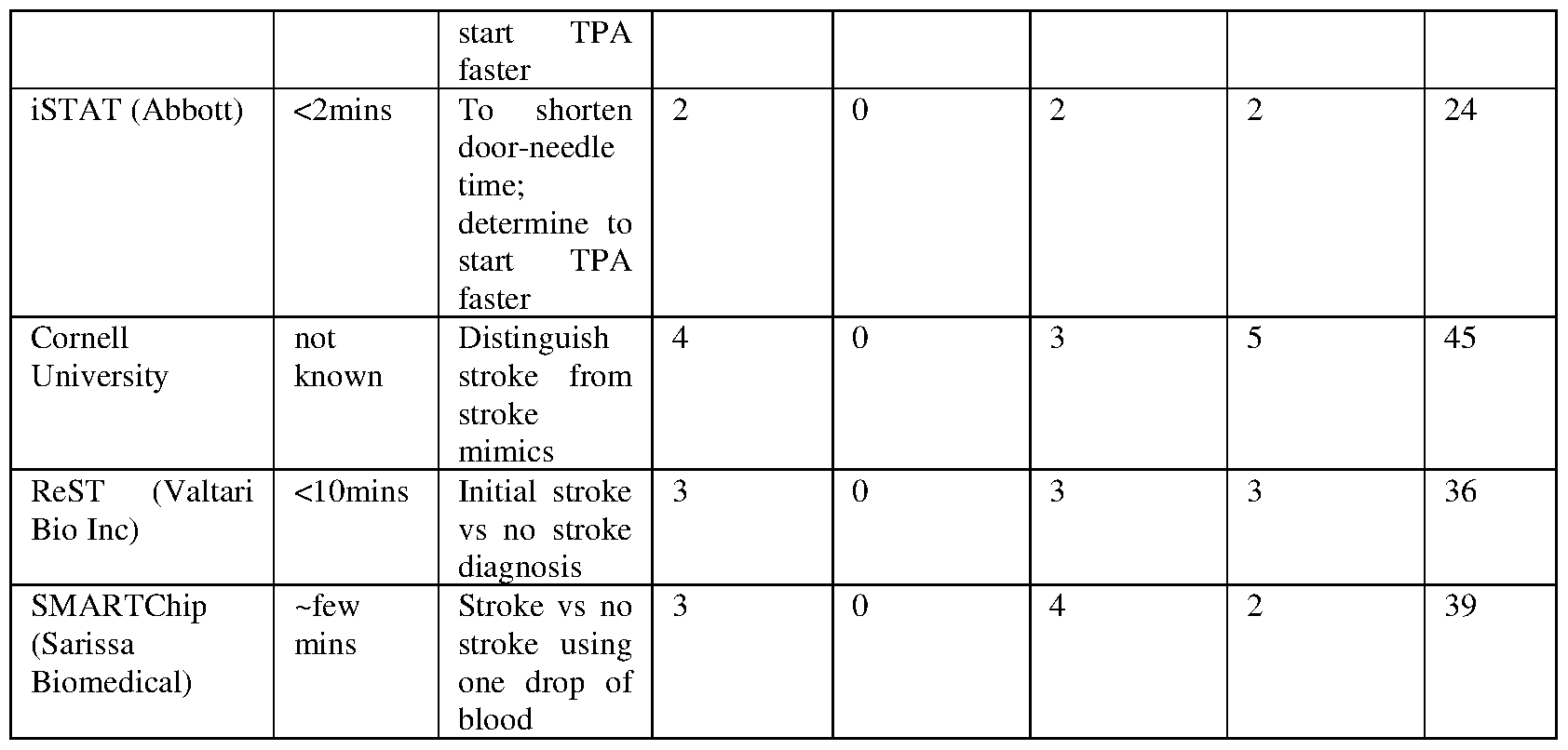


Claims
Priority Applications (5)
| Application Number | Priority Date | Filing Date | Title |
|---|---|---|---|
| JP2022522792A JP2022551988A (en) | 2019-10-15 | 2020-10-14 | Systems and methods for multivariate stroke detection |
| CA3157362A CA3157362A1 (en) | 2019-10-15 | 2020-10-14 | Systems and methods for multivariate stroke detection |
| CN202080009705.3A CN113347916A (en) | 2019-10-15 | 2020-10-14 | System and method for multivariate stroke detection |
| AU2020366348A AU2020366348A1 (en) | 2019-10-15 | 2020-10-14 | Systems and methods for multivariate stroke detection |
| EP20877443.0A EP4044906A4 (en) | 2019-10-15 | 2020-10-14 | Systems and methods for multivariate stroke detection |
Applications Claiming Priority (4)
| Application Number | Priority Date | Filing Date | Title |
|---|---|---|---|
| US201962915269P | 2019-10-15 | 2019-10-15 | |
| US62/915,269 | 2019-10-15 | ||
| US202063053265P | 2020-07-17 | 2020-07-17 | |
| US63/053,265 | 2020-07-17 |
Publications (1)
| Publication Number | Publication Date |
|---|---|
| WO2021076642A1 true WO2021076642A1 (en) | 2021-04-22 |
Family
ID=75382172
Family Applications (1)
| Application Number | Title | Priority Date | Filing Date |
|---|---|---|---|
| PCT/US2020/055604 WO2021076642A1 (en) | 2019-10-15 | 2020-10-14 | Systems and methods for multivariate stroke detection |
Country Status (7)
| Country | Link |
|---|---|
| US (3) | US11134859B2 (en) |
| EP (1) | EP4044906A4 (en) |
| JP (1) | JP2022551988A (en) |
| CN (1) | CN113347916A (en) |
| AU (1) | AU2020366348A1 (en) |
| CA (1) | CA3157362A1 (en) |
| WO (1) | WO2021076642A1 (en) |
Cited By (1)
| Publication number | Priority date | Publication date | Assignee | Title |
|---|---|---|---|---|
| US11426079B1 (en) | 2021-07-20 | 2022-08-30 | Fitbit, Inc. | Methods, systems, and devices for improved skin temperature monitoring |
Families Citing this family (20)
| Publication number | Priority date | Publication date | Assignee | Title |
|---|---|---|---|---|
| JP7012655B2 (en) | 2016-02-24 | 2022-01-28 | インセプト、リミテッド、ライアビリティ、カンパニー | Flexible enhanced neurovascular catheter |
| WO2018129194A1 (en) | 2017-01-06 | 2018-07-12 | Incept, Llc | Thromboresistant coatings for aneurysm treatment devices |
| US11395665B2 (en) | 2018-05-01 | 2022-07-26 | Incept, Llc | Devices and methods for removing obstructive material, from an intravascular site |
| CN112203593A (en) | 2018-05-01 | 2021-01-08 | 因赛普特有限责任公司 | Device and method for removing occlusive material from an intravascular site |
| US11517335B2 (en) | 2018-07-06 | 2022-12-06 | Incept, Llc | Sealed neurovascular extendable catheter |
| US11471582B2 (en) | 2018-07-06 | 2022-10-18 | Incept, Llc | Vacuum transfer tool for extendable catheter |
| US11766539B2 (en) | 2019-03-29 | 2023-09-26 | Incept, Llc | Enhanced flexibility neurovascular catheter |
| AU2020366348A1 (en) * | 2019-10-15 | 2022-05-12 | Imperative Care, Inc. | Systems and methods for multivariate stroke detection |
| JP2023507553A (en) | 2019-12-18 | 2023-02-24 | インパラティブ、ケア、インク. | Methods and systems for treating venous thromboembolism |
| US11457936B2 (en) | 2019-12-18 | 2022-10-04 | Imperative Care, Inc. | Catheter system for treating thromboembolic disease |
| US11633272B2 (en) | 2019-12-18 | 2023-04-25 | Imperative Care, Inc. | Manually rotatable thrombus engagement tool |
| EP4117762A4 (en) | 2020-03-10 | 2024-05-08 | Imperative Care Inc | Enhanced flexibility neurovascular catheter |
| US11207497B1 (en) | 2020-08-11 | 2021-12-28 | Imperative Care, Inc. | Catheter with enhanced tensile strength |
| WO2022090797A1 (en) * | 2020-10-26 | 2022-05-05 | Aquapass Ltd | Method and apparatus for early detection of worsening heart failure |
| EP4319618A1 (en) * | 2021-05-06 | 2024-02-14 | Huawei Technologies Co., Ltd. | System and method for determining risk of stroke for person |
| CN115371844A (en) * | 2021-05-21 | 2022-11-22 | 华为技术有限公司 | Wearable equipment |
| WO2023278858A1 (en) * | 2021-07-01 | 2023-01-05 | The Government Of The United States As Represented By The Secretary Of The Army | Thermoregulatory stress detection from skin temperature complexity |
| CN116185101A (en) * | 2021-11-26 | 2023-05-30 | Oppo广东移动通信有限公司 | Control circuit, method, wearable device, and readable storage medium |
| US20240021321A1 (en) * | 2022-07-13 | 2024-01-18 | Impact Vitals, Inc | Methods and devices for estimating hydration and heat stress physiological levels |
| CN116646070A (en) * | 2023-07-24 | 2023-08-25 | 深圳市联影高端医疗装备创新研究院 | Equipment and system for relieving restless leg syndrome |
Citations (6)
| Publication number | Priority date | Publication date | Assignee | Title |
|---|---|---|---|---|
| US20110178418A1 (en) * | 2008-09-22 | 2011-07-21 | Cheetah Medical, Inc. | System and method for determining blood flow |
| US20140276167A1 (en) * | 2013-03-15 | 2014-09-18 | Zansors Llc | Health monitoring, surveillance and anomaly detection |
| US20140276123A1 (en) * | 2013-03-15 | 2014-09-18 | Yingchang Yang | Metod and continuously wearable noninvasive apparatus for automatically detecting a stroke and other abnormal health conditions |
| US20140350645A1 (en) * | 2009-09-16 | 2014-11-27 | Board Of Regents, The University Of Texas System | Altering Temperature in a Mammalian Body |
| US20160151010A1 (en) * | 2013-07-17 | 2016-06-02 | Glucocheck Ltd. | Blood sampling device and methods |
| US20180289340A1 (en) * | 2015-10-28 | 2018-10-11 | Koninklijke Philips N.V. | Device and method for suv determination in emission tomography |
Family Cites Families (747)
| Publication number | Priority date | Publication date | Assignee | Title |
|---|---|---|---|---|
| US3605750A (en) | 1969-04-07 | 1971-09-20 | David S Sheridan | X-ray tip catheter |
| US3884242A (en) | 1971-03-29 | 1975-05-20 | Mpc Kurgisil | Catheter assembly |
| US3890976A (en) | 1972-10-26 | 1975-06-24 | Medical Products Corp | Catheter tip assembly |
| US3965901A (en) | 1974-10-03 | 1976-06-29 | American Hospital Supply Corporation | Suction catheter |
| US4030503A (en) | 1975-11-05 | 1977-06-21 | Clark Iii William T | Embolectomy catheter |
| US4319580A (en) | 1979-08-28 | 1982-03-16 | The Board Of Regents Of The University Of Washington | Method for detecting air emboli in the blood in an intracorporeal blood vessel |
| US4628168A (en) | 1980-05-14 | 1986-12-09 | Shiley, Inc. | Dielectric heating device for heating cannula members |
| DE3020041A1 (en) | 1980-05-24 | 1981-12-03 | Sartorius GmbH, 3400 Göttingen | FILTRATION DEVICE FOR CONCENTRATING LIQUID MEDIA |
| US4611594A (en) | 1984-04-11 | 1986-09-16 | Northwestern University | Medical instrument for containment and removal of calculi |
| US4617019A (en) | 1984-09-28 | 1986-10-14 | Sherwood Medical Company | Catheter |
| DE3442736A1 (en) | 1984-11-23 | 1986-06-05 | Tassilo Dr.med. 7800 Freiburg Bonzel | DILATATION CATHETER |
| US4619274A (en) | 1985-04-18 | 1986-10-28 | Advanced Cardiovascular Systems, Inc. | Torsional guide wire with attenuated diameter |
| US4810582A (en) | 1985-11-12 | 1989-03-07 | Tyndale Plains-Hunter Ltd. | Hydrophilic polyurethane composition |
| US5040548A (en) | 1989-06-01 | 1991-08-20 | Yock Paul G | Angioplasty mehtod |
| JPS6323645A (en) * | 1986-05-27 | 1988-01-30 | 住友電気工業株式会社 | Reflection heating type oxymeter |
| US4739768B2 (en) | 1986-06-02 | 1995-10-24 | Target Therapeutics Inc | Catheter for guide-wire tracking |
| US4767399A (en) | 1986-12-05 | 1988-08-30 | Fisher Scientific Group Inc. Dba Imed Corporation | Volumetric fluid withdrawal system |
| US4762130A (en) | 1987-01-15 | 1988-08-09 | Thomas J. Fogarty | Catheter with corkscrew-like balloon |
| US4923462A (en) | 1987-03-17 | 1990-05-08 | Cordis Corporation | Catheter system having a small diameter rotatable drive member |
| US4898575A (en) | 1987-08-31 | 1990-02-06 | Medinnovations, Inc. | Guide wire following tunneling catheter system and method for transluminal arterial atherectomy |
| US5217705A (en) | 1987-09-25 | 1993-06-08 | Neorx Corporation | Method of diagnosing blood clots using fibrin-binding proteins |
| US4844064A (en) | 1987-09-30 | 1989-07-04 | Baxter Travenol Laboratories, Inc. | Surgical cutting instrument with end and side openings |
| DE58906466D1 (en) | 1988-03-04 | 1994-02-03 | Angiomed Ag | Method and device for removing deposits in vessels and organs of living beings. |
| US5843156A (en) | 1988-08-24 | 1998-12-01 | Endoluminal Therapeutics, Inc. | Local polymeric gel cellular therapy |
| US5011488A (en) | 1988-12-07 | 1991-04-30 | Robert Ginsburg | Thrombus extraction system |
| DE8900059U1 (en) | 1989-01-04 | 1989-05-24 | Schneider (Europe) Ag, Zuerich, Ch | |
| JP2766317B2 (en) | 1989-06-22 | 1998-06-18 | コーリン電子株式会社 | Pulse oximeter |
| US5226909A (en) | 1989-09-12 | 1993-07-13 | Devices For Vascular Intervention, Inc. | Atherectomy device having helical blade and blade guide |
| US5120323A (en) | 1990-01-12 | 1992-06-09 | Schneider (Usa) Inc. | Telescoping guide catheter system |
| US5527292A (en) | 1990-10-29 | 1996-06-18 | Scimed Life Systems, Inc. | Intravascular device for coronary heart treatment |
| US5103827A (en) | 1990-12-14 | 1992-04-14 | Medasonics, Inc. | Apparatus for and a method of distinguishing ultrasound signals returned from bubbles and particles moving in a fluid from signals due to ultrasound transducer motion |
| US5916192A (en) | 1991-01-11 | 1999-06-29 | Advanced Cardiovascular Systems, Inc. | Ultrasonic angioplasty-atherectomy catheter and method of use |
| US5638818A (en) | 1991-03-21 | 1997-06-17 | Masimo Corporation | Low noise optical probe |
| US5290247A (en) | 1991-05-21 | 1994-03-01 | C. R. Bard, Inc. | Intracoronary exchange apparatus and method |
| US5234416A (en) | 1991-06-06 | 1993-08-10 | Advanced Cardiovascular Systems, Inc. | Intravascular catheter with a nontraumatic distal tip |
| ATE124225T1 (en) * | 1991-08-12 | 1995-07-15 | Avl Medical Instr Ag | DEVICE FOR MEASURING AT LEAST ONE GAS SATURATION, IN PARTICULAR THE OXYGEN SATURATION OF BLOOD. |
| US5423846A (en) | 1991-10-21 | 1995-06-13 | Cathco, Inc. | Dottering auger catheter system |
| US5308327A (en) | 1991-11-25 | 1994-05-03 | Advanced Surgical Inc. | Self-deployed inflatable retractor |
| US5261916A (en) | 1991-12-12 | 1993-11-16 | Target Therapeutics | Detachable pusher-vasoocclusive coil assembly with interlocking ball and keyway coupling |
| US5413560A (en) | 1992-03-30 | 1995-05-09 | Pameda N.V. | Method of rapid catheter exchange |
| WO1993019679A1 (en) | 1992-04-07 | 1993-10-14 | The Johns Hopkins University | A percutaneous mechanical fragmentation catheter system |
| US5328472A (en) | 1992-07-27 | 1994-07-12 | Medtronic, Inc. | Catheter with flexible side port entry |
| FR2696924B1 (en) | 1992-08-06 | 1995-01-06 | Domilens Laboratoires | Surgical instrument for the in situ fragmentation of a living material, in particular a phaco-fragmentation or phaco-emulsification instrument. |
| WO1994003230A1 (en) | 1992-08-07 | 1994-02-17 | Boston Scientific Corporation | Support catheter assembly |
| US5243997A (en) | 1992-09-14 | 1993-09-14 | Interventional Technologies, Inc. | Vibrating device for a guide wire |
| US5474563A (en) | 1993-03-25 | 1995-12-12 | Myler; Richard | Cardiovascular stent and retrieval apparatus |
| US5417697A (en) | 1993-07-07 | 1995-05-23 | Wilk; Peter J. | Polyp retrieval assembly with cauterization loop and suction web |
| DE4329898A1 (en) | 1993-09-04 | 1995-04-06 | Marcus Dr Besson | Wireless medical diagnostic and monitoring device |
| US6858024B1 (en) | 1994-02-14 | 2005-02-22 | Scimed Life Systems, Inc. | Guide catheter having selected flexural modulus segments |
| ATE295127T1 (en) | 1994-03-03 | 2005-05-15 | Boston Scient Ltd | DEVICE FOR DETECTING THE DIVISION OF A VASS OCCLUSION DEVICE |
| US5466222A (en) | 1994-03-30 | 1995-11-14 | Scimed Life Systems, Inc. | Longitudinally collapsible and exchangeable catheter |
| US5454795A (en) | 1994-06-27 | 1995-10-03 | Target Therapeutics, Inc. | Kink-free spiral-wound catheter |
| US5549119A (en) | 1994-09-13 | 1996-08-27 | Cordis Corporation | Vibrating tip catheter |
| DE19504261A1 (en) | 1995-02-09 | 1996-09-12 | Krieg Gunther | Angioplasty catheter for dilating and / or opening blood vessels |
| US5441051A (en) | 1995-02-09 | 1995-08-15 | Hileman; Ronald E. | Method and apparatus for the non-invasive detection and classification of emboli |
| CA2213522C (en) | 1995-03-28 | 2009-01-06 | Straub Federnfabrik Ag | Catheter for detaching abnormal deposits in human blood vessels |
| CZ287289B6 (en) | 1995-03-28 | 2000-10-11 | Straub Medical Ag | Catheter |
| US5662622A (en) | 1995-04-04 | 1997-09-02 | Cordis Corporation | Intravascular catheter |
| US5702373A (en) | 1995-08-31 | 1997-12-30 | Target Therapeutics, Inc. | Composite super-elastic alloy braid reinforced catheter |
| US5658263A (en) | 1995-05-18 | 1997-08-19 | Cordis Corporation | Multisegmented guiding catheter for use in medical catheter systems |
| US5814038A (en) | 1995-06-07 | 1998-09-29 | Sri International | Surgical manipulator for a telerobotic system |
| US5591187A (en) | 1995-07-14 | 1997-01-07 | Dekel; Moshe | Laparoscopic tissue retrieval device and method |
| US5776141A (en) | 1995-08-28 | 1998-07-07 | Localmed, Inc. | Method and apparatus for intraluminal prosthesis delivery |
| US5569178A (en) | 1995-10-20 | 1996-10-29 | Henley; Julian L. | Power assisted suction lipectomy device |
| US5885209A (en) | 1996-02-02 | 1999-03-23 | Green; Anthony D. | Endoscopic working channel and method of making same |
| US5895398A (en) | 1996-02-02 | 1999-04-20 | The Regents Of The University Of California | Method of using a clot capture coil |
| US6022336A (en) | 1996-05-20 | 2000-02-08 | Percusurge, Inc. | Catheter system for emboli containment |
| SE505822C2 (en) | 1996-05-23 | 1997-10-13 | Elekta Ab | Device for injecting a substance into a body, especially human or animal |
| US5782811A (en) | 1996-05-30 | 1998-07-21 | Target Therapeutics, Inc. | Kink-resistant braided catheter with distal side holes |
| US5899892A (en) | 1996-05-31 | 1999-05-04 | Scimed Life Systems, Inc. | Catheter having distal fiber braid |
| US5827242A (en) | 1996-06-21 | 1998-10-27 | Medtronic, Inc. | Reinforced catheter body and method for its fabrication |
| US5735816A (en) | 1996-07-23 | 1998-04-07 | Medtronic, Inc. | Spiral sheath retainer for autoperfusion dilatation catheter balloon |
| US6221038B1 (en) | 1996-11-27 | 2001-04-24 | Pharmasonics, Inc. | Apparatus and methods for vibratory intraluminal therapy employing magnetostrictive transducers |
| US5690613A (en) | 1996-12-06 | 1997-11-25 | Medtronic, Inc. | Rapid exchange high pressure transition for high pressure catheter with non-compliant balloon |
| US8529582B2 (en) | 1996-12-12 | 2013-09-10 | Intuitive Surgical Operations, Inc. | Instrument interface of a robotic surgical system |
| US6582440B1 (en) | 1996-12-26 | 2003-06-24 | Misonix Incorporated | Non-clogging catheter for lithotrity |
| US20020026145A1 (en) | 1997-03-06 | 2002-02-28 | Bagaoisan Celso J. | Method and apparatus for emboli containment |
| US6355016B1 (en) | 1997-03-06 | 2002-03-12 | Medtronic Percusurge, Inc. | Catheter core wire |
| US5843103A (en) | 1997-03-06 | 1998-12-01 | Scimed Life Systems, Inc. | Shaped wire rotational atherectomy device |
| US6059745A (en) | 1997-05-20 | 2000-05-09 | Gelbfish; Gary A. | Thrombectomy device and associated method |
| US6228046B1 (en) | 1997-06-02 | 2001-05-08 | Pharmasonics, Inc. | Catheters comprising a plurality of oscillators and methods for their use |
| US5951539A (en) | 1997-06-10 | 1999-09-14 | Target Therpeutics, Inc. | Optimized high performance multiple coil spiral-wound vascular catheter |
| US5928260A (en) | 1997-07-10 | 1999-07-27 | Scimed Life Systems, Inc. | Removable occlusion system for aneurysm neck |
| US6090118A (en) | 1998-07-23 | 2000-07-18 | Mcguckin, Jr.; James F. | Rotational thrombectomy apparatus and method with standing wave |
| WO1999004826A1 (en) | 1997-07-24 | 1999-02-04 | The Australian National University | Method for detection of fibrin clots |
| US5891114A (en) | 1997-09-30 | 1999-04-06 | Target Therapeutics, Inc. | Soft-tip high performance braided catheter |
| US5935112A (en) | 1997-10-15 | 1999-08-10 | Stevens; Brian W. | Hemostasis valve with catheter/guidewire seals |
| US5908435A (en) | 1997-10-23 | 1999-06-01 | Samuels; Shaun L. W. | Expandable lumen device and method of use |
| US20100030256A1 (en) | 1997-11-12 | 2010-02-04 | Genesis Technologies Llc | Medical Devices and Methods |
| US6183432B1 (en) | 1997-11-13 | 2001-02-06 | Lumend, Inc. | Guidewire and catheter with rotating and reciprocating symmetrical or asymmetrical distal tip |
| WO1999039648A1 (en) | 1998-02-10 | 1999-08-12 | Dubrul William R | Entrapping apparatus and method for use |
| US6824550B1 (en) | 2000-04-06 | 2004-11-30 | Norbon Medical, Inc. | Guidewire for crossing occlusions or stenosis |
| US6796976B1 (en) | 1998-03-06 | 2004-09-28 | Scimed Life Systems, Inc. | Establishing access to the body |
| IE980241A1 (en) | 1998-04-02 | 1999-10-20 | Salviac Ltd | Delivery catheter with split sheath |
| US6482217B1 (en) | 1998-04-10 | 2002-11-19 | Endicor Medical, Inc. | Neuro thrombectomy catheter |
| US6666874B2 (en) | 1998-04-10 | 2003-12-23 | Endicor Medical, Inc. | Rotational atherectomy system with serrated cutting tip |
| US6511492B1 (en) | 1998-05-01 | 2003-01-28 | Microvention, Inc. | Embolectomy catheters and methods for treating stroke and other small vessel thromboembolic disorders |
| US6740104B1 (en) | 1998-05-15 | 2004-05-25 | Advanced Cardiovascular Systems, Inc. | Enhanced catheter with alignment means |
| JP2002516689A (en) | 1998-06-03 | 2002-06-11 | マシモ・コーポレイション | Stereo pulse oximeter |
| US6368316B1 (en) | 1998-06-11 | 2002-04-09 | Target Therapeutics, Inc. | Catheter with composite stiffener |
| US6024575A (en) | 1998-06-29 | 2000-02-15 | Paul C. Ulrich | Arrangement for monitoring physiological signals |
| US6285903B1 (en) | 1998-06-30 | 2001-09-04 | Eclipse Surgical Technologies, Inc. | Intracorporeal device with radiopaque marker |
| AU3378499A (en) | 1998-06-30 | 2000-01-17 | Gynecare, Inc | Endometrial balloon ablation catheter having heater |
| US6356774B1 (en) | 1998-09-29 | 2002-03-12 | Mallinckrodt, Inc. | Oximeter sensor with encoded temperature characteristic |
| US6214036B1 (en) | 1998-11-09 | 2001-04-10 | Cordis Corporation | Stent which is easily recaptured and repositioned within the body |
| US6196972B1 (en) | 1998-11-11 | 2001-03-06 | Spentech, Inc. | Doppler ultrasound method and apparatus for monitoring blood flow |
| US6591472B1 (en) | 1998-12-08 | 2003-07-15 | Medtronic, Inc. | Multiple segment catheter and method of fabrication |
| DE69902986D1 (en) | 1998-12-09 | 2002-10-24 | Jms Co Ltd | infusion filters |
| US6165199A (en) | 1999-01-12 | 2000-12-26 | Coaxia, Inc. | Medical device for removing thromboembolic material from cerebral arteries and methods of use |
| US6171295B1 (en) | 1999-01-20 | 2001-01-09 | Scimed Life Systems, Inc. | Intravascular catheter with composite reinforcement |
| JP4213350B2 (en) | 1999-01-20 | 2009-01-21 | ボストン サイエンティフィック リミテッド | Vascular catheter with composite reinforcement |
| WO2000044428A1 (en) | 1999-01-28 | 2000-08-03 | Ansamed Limited | Catheter with an expandable end portion |
| US6350271B1 (en) | 1999-05-17 | 2002-02-26 | Micrus Corporation | Clot retrieval device |
| EP1867300A3 (en) | 1999-06-02 | 2008-02-27 | Sethel Interventional, Inc. | Intracorporeal occlusive device |
| US6355027B1 (en) | 1999-06-09 | 2002-03-12 | Possis Medical, Inc. | Flexible microcatheter |
| US6458139B1 (en) | 1999-06-21 | 2002-10-01 | Endovascular Technologies, Inc. | Filter/emboli extractor for use in variable sized blood vessels |
| US6179859B1 (en) | 1999-07-16 | 2001-01-30 | Baff Llc | Emboli filtration system and methods of use |
| WO2001007101A1 (en) | 1999-07-23 | 2001-02-01 | Tfx Medical Extrusion Products | Catheter device having multi-lumen reinforced shaft and method of manufacture for same |
| US6887199B2 (en) | 1999-09-23 | 2005-05-03 | Active Signal Technologies, Inc. | Brain assessment monitor |
| US6400971B1 (en) | 1999-10-12 | 2002-06-04 | Orsense Ltd. | Optical device for non-invasive measurement of blood-related signals and a finger holder therefor |
| AU1361901A (en) | 1999-11-03 | 2001-05-14 | Endocare, Inc. | Method of loading a stent on a delivery catheter |
| US7037267B1 (en) | 1999-11-10 | 2006-05-02 | David Lipson | Medical diagnostic methods, systems, and related equipment |
| DE19959230C1 (en) | 1999-12-08 | 2001-04-05 | Fresenius Medical Care De Gmbh | Two-sheet pouch, used as disposable haemodialysis container, comprises top and bottom closed by convex weld seams and is repeatedly folded parallel to its vertical axis |
| US6206852B1 (en) | 1999-12-15 | 2001-03-27 | Advanced Cardiovascular Systems, Inc. | Balloon catheter having a small profile catheter |
| US6579246B2 (en) | 1999-12-22 | 2003-06-17 | Sarcos, Lc | Coronary guidewire system |
| US6520934B1 (en) | 1999-12-29 | 2003-02-18 | Advanced Cardiovascular Systems, Inc. | Catheter assemblies with flexible radiopaque marker |
| AU2607901A (en) | 1999-12-31 | 2001-07-16 | Bacchus Vascular Inc. | Method and system for re-infusing filtered bodily aspirates |
| US6394976B1 (en) | 2000-01-31 | 2002-05-28 | Intraluminal Therapeutics, Inc. | Catheter for controlling the advancement of a guide wire |
| JP3915862B2 (en) | 2000-02-09 | 2007-05-16 | テルモ株式会社 | catheter |
| US6554820B1 (en) | 2000-03-08 | 2003-04-29 | Scimed Life Systems, Inc. | Composite flexible tube for medical applications |
| US6719717B1 (en) | 2000-03-17 | 2004-04-13 | Advanced Research & Technology Institute, Inc. | Thrombectomy treatment system and method |
| US7713227B2 (en) | 2000-03-20 | 2010-05-11 | Michael Wholey | Method and apparatus for medical device for aspiration of thromboemobolic debris |
| US6514273B1 (en) | 2000-03-22 | 2003-02-04 | Endovascular Technologies, Inc. | Device for removal of thrombus through physiological adhesion |
| US6468301B1 (en) | 2000-03-27 | 2002-10-22 | Aga Medical Corporation | Repositionable and recapturable vascular stent/graft |
| US20010031981A1 (en) | 2000-03-31 | 2001-10-18 | Evans Michael A. | Method and device for locating guidewire and treating chronic total occlusions |
| US20050165276A1 (en) | 2004-01-28 | 2005-07-28 | Amir Belson | Methods and apparatus for accessing and treating regions of the body |
| US7366561B2 (en) | 2000-04-07 | 2008-04-29 | Medtronic, Inc. | Robotic trajectory guide |
| US6638268B2 (en) | 2000-04-07 | 2003-10-28 | Imran K. Niazi | Catheter to cannulate the coronary sinus |
| US6468219B1 (en) | 2000-04-24 | 2002-10-22 | Philip Chidi Njemanze | Implantable telemetric transcranial doppler device |
| US8133698B2 (en) | 2000-05-15 | 2012-03-13 | Silver James H | Sensors for detecting substances indicative of stroke, ischemia, infection or inflammation |
| IL136213A0 (en) | 2000-05-17 | 2001-05-20 | Xtent Medical Inc | Selectively expandable and releasable stent |
| US6890315B1 (en) | 2000-05-23 | 2005-05-10 | Chf Solutions, Inc. | Method and apparatus for vein fluid removal in heart failure |
| US6605038B1 (en) | 2000-06-16 | 2003-08-12 | Bodymedia, Inc. | System for monitoring health, wellness and fitness |
| KR100387384B1 (en) | 2000-07-26 | 2003-06-12 | 규 호 이 | Embolic material detachment detection system and method and assembly for embolic treatments |
| US6613017B1 (en) | 2000-08-08 | 2003-09-02 | Scimed Life Systems, Inc. | Controlled depth injection device and method |
| US6776770B1 (en) | 2000-09-07 | 2004-08-17 | Advanced Research & Technology Institute | Thromboaspiration valve-filter device and methods |
| US6524303B1 (en) | 2000-09-08 | 2003-02-25 | Stereotaxis, Inc. | Variable stiffness magnetic catheter |
| CA2424306A1 (en) | 2000-10-18 | 2002-04-25 | Nmt Medical, Inc. | Medical implant delivery system |
| US20060100530A1 (en) | 2000-11-28 | 2006-05-11 | Allez Physionix Limited | Systems and methods for non-invasive detection and monitoring of cardiac and blood parameters |
| US6554827B2 (en) | 2000-12-11 | 2003-04-29 | Scimed Life Systems, Inc. | Radio frequency ablation system |
| US6533751B2 (en) | 2001-01-09 | 2003-03-18 | Andrew Cragg | Micro catheter and guidewire system having improved pushability and control |
| US20030135204A1 (en) | 2001-02-15 | 2003-07-17 | Endo Via Medical, Inc. | Robotically controlled medical instrument with a flexible section |
| US8414505B1 (en) | 2001-02-15 | 2013-04-09 | Hansen Medical, Inc. | Catheter driver system |
| US7766894B2 (en) | 2001-02-15 | 2010-08-03 | Hansen Medical, Inc. | Coaxial catheter system |
| US6673023B2 (en) | 2001-03-23 | 2004-01-06 | Stryker Puerto Rico Limited | Micro-invasive breast biopsy device |
| US20020156460A1 (en) | 2001-04-20 | 2002-10-24 | Scimed Life Systems, Inc | Microcatheter with improved distal tip and transitions |
| US20020156459A1 (en) | 2001-04-20 | 2002-10-24 | Scimed Life Systems, Inc | Microcatheter with improved distal tip and transitions |
| US7635342B2 (en) | 2001-05-06 | 2009-12-22 | Stereotaxis, Inc. | System and methods for medical device advancement and rotation |
| US20020188314A1 (en) | 2001-06-07 | 2002-12-12 | Microvena Corporation | Radiopaque distal embolic protection device |
| US6818013B2 (en) | 2001-06-14 | 2004-11-16 | Cordis Corporation | Intravascular stent device |
| DE20110121U1 (en) | 2001-06-19 | 2002-12-05 | Braun Melsungen Ag | catheter |
| US8252040B2 (en) | 2001-07-20 | 2012-08-28 | Microvention, Inc. | Aneurysm treatment device and method of use |
| US8715312B2 (en) | 2001-07-20 | 2014-05-06 | Microvention, Inc. | Aneurysm treatment device and method of use |
| EP1438083A1 (en) | 2001-10-03 | 2004-07-21 | Boston Scientific Limited | Medical device with polymer coated inner lumen |
| US20030088266A1 (en) | 2001-11-02 | 2003-05-08 | Bowlin Gary L. | Method of fusing electroprocessed matrices to a substrate |
| AU2002367387B2 (en) | 2001-12-26 | 2009-05-21 | Yale University | Vascular access device |
| US7335216B2 (en) | 2002-01-22 | 2008-02-26 | Cardica, Inc. | Tool for creating an opening in tissue |
| US7029482B1 (en) | 2002-01-22 | 2006-04-18 | Cardica, Inc. | Integrated anastomosis system |
| US7223274B2 (en) | 2002-01-23 | 2007-05-29 | Cardica, Inc. | Method of performing anastomosis |
| US7087026B2 (en) | 2002-03-21 | 2006-08-08 | Radiant Medical, Inc. | Devices and methods for measuring blood flow rate or cardiac output and for heating or cooling the body |
| US7232452B2 (en) | 2002-07-12 | 2007-06-19 | Ev3 Inc. | Device to create proximal stasis |
| US8425549B2 (en) | 2002-07-23 | 2013-04-23 | Reverse Medical Corporation | Systems and methods for removing obstructive matter from body lumens and treating vascular defects |
| US7309334B2 (en) | 2002-07-23 | 2007-12-18 | Von Hoffmann Gerard | Intracranial aspiration catheter |
| US20070225614A1 (en) * | 2004-05-26 | 2007-09-27 | Endothelix, Inc. | Method and apparatus for determining vascular health conditions |
| US20040045645A1 (en) | 2002-09-10 | 2004-03-11 | Scimed Life Systems, Inc. | Shaped reinforcing member for medical device and method for making the same |
| US7060051B2 (en) | 2002-09-24 | 2006-06-13 | Scimed Life Systems, Inc. | Multi-balloon catheter with hydrogel coating |
| US20070043333A1 (en) | 2002-10-03 | 2007-02-22 | Scimed Life Systems, Inc. | Method for forming a medical device with a polymer coated inner lumen |
| AU2003277361A1 (en) | 2002-10-10 | 2004-05-04 | Micro Therapeutics, Inc. | Wire braid-reinforced microcatheter |
| US6814746B2 (en) | 2002-11-01 | 2004-11-09 | Ev3 Peripheral, Inc. | Implant delivery system with marker interlock |
| US7599730B2 (en) | 2002-11-19 | 2009-10-06 | Medtronic Navigation, Inc. | Navigation system for cardiac therapies |
| US20040138693A1 (en) | 2003-01-14 | 2004-07-15 | Scimed Life Systems, Inc. | Snare retrievable embolic protection filter with guidewire stopper |
| US8016752B2 (en) | 2003-01-17 | 2011-09-13 | Gore Enterprise Holdings, Inc. | Puncturable catheter |
| JP2004275435A (en) | 2003-03-14 | 2004-10-07 | Terumo Corp | Catheter |
| US7001369B2 (en) | 2003-03-27 | 2006-02-21 | Scimed Life Systems, Inc. | Medical device |
| US20040199201A1 (en) | 2003-04-02 | 2004-10-07 | Scimed Life Systems, Inc. | Embolectomy devices |
| ATE381913T1 (en) | 2003-04-02 | 2008-01-15 | Boston Scient Ltd | REMOVABLE AND RETURNABLE STENT ASSEMBLY |
| US7413563B2 (en) | 2003-05-27 | 2008-08-19 | Cardia, Inc. | Flexible medical device |
| CA2528959C (en) | 2003-06-10 | 2011-12-20 | Lumend, Inc. | Catheter systems and methods for crossing vascular occlusions |
| WO2005004967A2 (en) | 2003-07-02 | 2005-01-20 | Cook Incorporated | Small gauge needle catheterization apparatus |
| US20050004553A1 (en) | 2003-07-02 | 2005-01-06 | Medtronic Ave, Inc. | Sheath catheter having variable over-the-wire length and methods of use |
| WO2005025643A2 (en) | 2003-09-04 | 2005-03-24 | Secant Medical, Llc | Endovascular snare for capture and removal of arterial emboli |
| US8034003B2 (en) | 2003-09-11 | 2011-10-11 | Depuy Mitek, Inc. | Tissue extraction and collection device |
| US7588555B2 (en) | 2003-09-24 | 2009-09-15 | Enpath Medical, Inc. | Bi-directional catheter assembly and method therefor |
| US20050103332A1 (en) | 2003-11-17 | 2005-05-19 | Bruce Gingles | Airway exchange catheter |
| EP1696806B1 (en) | 2003-11-21 | 2012-08-29 | Silk Road Medical, Inc. | Apparatus for treating a carotid artery |
| US8382739B2 (en) | 2003-12-02 | 2013-02-26 | Boston Scientific Scimed, Inc. | Composite medical device and method of forming |
| US20050153309A1 (en) | 2003-12-22 | 2005-07-14 | David Hoon | Method and apparatus for in vivo surveillance of circulating biological components |
| US7763011B2 (en) | 2003-12-22 | 2010-07-27 | Boston Scientific Scimed, Inc. | Variable density braid stent |
| ATE493097T1 (en) | 2004-01-23 | 2011-01-15 | Iscience Interventional Corp | COMPOSITE OPHTHALMIC MICRO CANNULA |
| US20050182386A1 (en) | 2004-02-17 | 2005-08-18 | Steen Aggerholm | Catheter with stiffening element |
| US8157792B2 (en) | 2004-02-26 | 2012-04-17 | Haemonetics Corporation | Wound drainage suction relief |
| EP1722694B1 (en) | 2004-03-04 | 2009-05-20 | Straub Medical AG | Catheter for sucking, fragmenting removing material extractable from blood vessels |
| US8021326B2 (en) | 2004-03-05 | 2011-09-20 | Hansen Medical, Inc. | Instrument driver for robotic catheter system |
| WO2005087128A1 (en) | 2004-03-05 | 2005-09-22 | Hansen Medical, Inc. | Robotic catheter system |
| US7974681B2 (en) | 2004-03-05 | 2011-07-05 | Hansen Medical, Inc. | Robotic catheter system |
| US8747453B2 (en) | 2008-02-18 | 2014-06-10 | Aga Medical Corporation | Stent/stent graft for reinforcement of vascular abnormalities and associated method |
| US7686825B2 (en) | 2004-03-25 | 2010-03-30 | Hauser David L | Vascular filter device |
| US8535293B2 (en) | 2004-04-13 | 2013-09-17 | Gyrus Acmi, Inc. | Atraumatic ureteral access sheath |
| US8235968B2 (en) | 2004-04-13 | 2012-08-07 | Gyrus Acmi, Inc. | Atraumatic ureteral access sheath |
| US7379790B2 (en) | 2004-05-04 | 2008-05-27 | Intuitive Surgical, Inc. | Tool memory-based software upgrades for robotic surgery |
| EP1750619B1 (en) | 2004-05-25 | 2013-07-24 | Covidien LP | Flexible vascular occluding device |
| US7815627B2 (en) | 2004-05-27 | 2010-10-19 | Abbott Laboratories | Catheter having plurality of stiffening members |
| US9782130B2 (en) | 2004-05-28 | 2017-10-10 | St. Jude Medical, Atrial Fibrillation Division, Inc. | Robotic surgical system |
| US7632265B2 (en) | 2004-05-28 | 2009-12-15 | St. Jude Medical, Atrial Fibrillation Division, Inc. | Radio frequency ablation servo catheter and method |
| US10258285B2 (en) | 2004-05-28 | 2019-04-16 | St. Jude Medical, Atrial Fibrillation Division, Inc. | Robotic surgical system and method for automated creation of ablation lesions |
| US9492084B2 (en) | 2004-06-18 | 2016-11-15 | Adidas Ag | Systems and methods for monitoring subjects in potential physiological distress |
| US20060030835A1 (en) | 2004-06-29 | 2006-02-09 | Sherman Darren R | Catheter shaft tubes and methods of making |
| WO2006020943A1 (en) | 2004-08-12 | 2006-02-23 | Hansen Medical, Inc. | Robotically controlled intravascular tissue injection system |
| CA2578076C (en) | 2004-08-25 | 2016-04-26 | Microvention, Inc. | Thermal detachment system for implantable devices |
| US7931659B2 (en) | 2004-09-10 | 2011-04-26 | Penumbra, Inc. | System and method for treating ischemic stroke |
| US9655633B2 (en) | 2004-09-10 | 2017-05-23 | Penumbra, Inc. | System and method for treating ischemic stroke |
| US20060064036A1 (en) | 2004-09-21 | 2006-03-23 | Cook Incorporated | Variable flexibility wire guide |
| US7306585B2 (en) | 2004-09-30 | 2007-12-11 | Engineering Resources Group, Inc. | Guide catheter |
| JP2006102222A (en) | 2004-10-06 | 2006-04-20 | Sekisui Chem Co Ltd | Detachable balloon catheter |
| US7621904B2 (en) | 2004-10-21 | 2009-11-24 | Boston Scientific Scimed, Inc. | Catheter with a pre-shaped distal tip |
| CA2585475A1 (en) | 2004-11-01 | 2006-05-11 | Medical Components, Inc. | Universal catheter tunneler |
| US20060217664A1 (en) | 2004-11-15 | 2006-09-28 | Hattler Brack G | Telescoping vascular dilator |
| EP1827555A4 (en) | 2004-11-18 | 2010-03-10 | David W Chang | Endoluminal delivery of anesthesia |
| US20060111649A1 (en) | 2004-11-19 | 2006-05-25 | Scimed Life Systems, Inc. | Catheter having improved torque response and curve retention |
| US20080086110A1 (en) | 2004-11-19 | 2008-04-10 | Galdonik Jason A | Extendable Device On An Aspiration Catheter |
| US20060200026A1 (en) | 2005-01-13 | 2006-09-07 | Hansen Medical, Inc. | Robotic catheter system |
| DE602006021291D1 (en) | 2005-04-20 | 2011-05-26 | Cook Inc | INTERNAL CONNECTOR FOR MEDICAL EMISSION SYSTEMS |
| WO2006119495A2 (en) | 2005-05-03 | 2006-11-09 | Hansen Medical, Inc. | Robotic catheter system |
| US7806871B2 (en) | 2005-05-09 | 2010-10-05 | Boston Scientific Scimed, Inc. | Method and device for tissue removal and for delivery of a therapeutic agent or bulking agent |
| US9014786B2 (en) | 2005-05-11 | 2015-04-21 | Eyoca Medical Ltd. | Device and method for opening vascular obstructions |
| US7771358B2 (en) | 2005-05-20 | 2010-08-10 | Spentech, Inc. | System and method for grading microemboli monitored by a multi-gate doppler ultrasound system |
| US20120330196A1 (en) | 2005-06-24 | 2012-12-27 | Penumbra Inc. | Methods and Apparatus for Removing Blood Clots and Tissue from the Patient's Head |
| US20120078140A1 (en) | 2005-06-24 | 2012-03-29 | Penumbra, Inc. | Method and Apparatus for Removing Blood Clots and Tissue from the Patient's Head |
| WO2007005976A1 (en) | 2005-07-01 | 2007-01-11 | Hansen Medical, Inc. | Robotic catheter system |
| CN101247847B (en) | 2005-07-11 | 2013-01-09 | 导管机器人技术公司 | Remotely controlled catheter insertion system |
| US7938820B2 (en) | 2005-08-18 | 2011-05-10 | Lumen Biomedical, Inc. | Thrombectomy catheter |
| US8021351B2 (en) | 2005-08-18 | 2011-09-20 | Medtronic Vascular, Inc. | Tracking aspiration catheter |
| US20070060888A1 (en) | 2005-09-06 | 2007-03-15 | Kerberos Proximal Solutions, Inc. | Methods and apparatus for assisted aspiration |
| US20080188928A1 (en) | 2005-09-16 | 2008-08-07 | Amr Salahieh | Medical device delivery sheath |
| US7850623B2 (en) | 2005-10-27 | 2010-12-14 | Boston Scientific Scimed, Inc. | Elongate medical device with continuous reinforcement member |
| RU2304926C2 (en) * | 2005-10-28 | 2007-08-27 | Государственное учреждение Российский научный центр хирургии им. акад. Б.В.Петровского Российской академии медицинских наук | Method for evaluating the reserve of limb's circulation |
| JP5154432B2 (en) | 2005-11-17 | 2013-02-27 | マイクロベンション インコーポレイテッド | 3D complex coil |
| US20080262350A1 (en) | 2005-11-18 | 2008-10-23 | Imarx Therapeutics, Inc. | Ultrasound Apparatus and Method to Treat an Ischemic Stroke |
| US20070185521A1 (en) | 2005-12-05 | 2007-08-09 | Cook Incorporated | Rapid exchange assembly |
| US8498691B2 (en) | 2005-12-09 | 2013-07-30 | Hansen Medical, Inc. | Robotic catheter system and methods |
| US8190238B2 (en) | 2005-12-09 | 2012-05-29 | Hansen Medical, Inc. | Robotic catheter system and methods |
| EP1965852A4 (en) | 2005-12-30 | 2012-10-31 | Bard Inc C R | Embolus blood clot filter removal system and method |
| US20070208302A1 (en) | 2006-01-26 | 2007-09-06 | Webster Mark W | Deflection control catheters, support catheters and methods of use |
| JP2009525121A (en) | 2006-02-02 | 2009-07-09 | レリーフ メディカル リミテッド | Shock wave generator for treatment of calcific aortic stenosis and method of use thereof |
| US7608063B2 (en) | 2006-02-23 | 2009-10-27 | Medrad, Inc. | Dual lumen aspiration catheter system |
| JP5236505B2 (en) | 2006-03-08 | 2013-07-17 | コーニンクレッカ フィリップス エレクトロニクス エヌ ヴィ | Method and system for monitoring functional use of limbs |
| US9615832B2 (en) | 2006-04-07 | 2017-04-11 | Penumbra, Inc. | Aneurysm occlusion system and method |
| US20120150147A1 (en) | 2010-12-08 | 2012-06-14 | Penumbra, Inc. | System and method for treating ischemic stroke |
| US8048032B2 (en) | 2006-05-03 | 2011-11-01 | Vascular Solutions, Inc. | Coaxial guide catheter for interventional cardiology procedures |
| US7905877B1 (en) | 2006-05-12 | 2011-03-15 | Micrus Design Technology, Inc. | Double helix reinforced catheter |
| US9814425B2 (en) | 2006-05-12 | 2017-11-14 | Koninklijke Philips N.V. | Health monitoring appliance |
| US7558622B2 (en) | 2006-05-24 | 2009-07-07 | Bao Tran | Mesh network stroke monitoring appliance |
| US7803136B2 (en) | 2006-06-05 | 2010-09-28 | Schatz Richard A | Myocardial injector |
| EP2027729A2 (en) | 2006-06-15 | 2009-02-25 | MicroVention, Inc. | Embolization device constructed from expansible polymer |
| US20080097251A1 (en) | 2006-06-15 | 2008-04-24 | Eilaz Babaev | Method and apparatus for treating vascular obstructions |
| KR20090037906A (en) | 2006-06-30 | 2009-04-16 | 아테로메드, 아이엔씨. | Atherectomy devices and methods |
| WO2008091584A2 (en) | 2007-01-22 | 2008-07-31 | Cv Devices, Llc | Devices, systems and methods for an epicardial cardiac monitoring system |
| WO2008005261A2 (en) | 2006-07-05 | 2008-01-10 | Wilson-Cook Medical Inc. | Suction clip |
| WO2008014425A2 (en) | 2006-07-26 | 2008-01-31 | Hansen Medical, Inc. | Systems for performing minimally invasive surgical operations |
| US8211023B2 (en) | 2006-08-11 | 2012-07-03 | Koninklijke Philips Electronics N.V. | Ultrasound system for cerebral blood flow monitoring |
| US20080097476A1 (en) | 2006-09-01 | 2008-04-24 | Voyage Medical, Inc. | Precision control systems for tissue visualization and manipulation assemblies |
| US8394078B2 (en) | 2006-10-04 | 2013-03-12 | Medrad, Inc. | Interventional catheters incorporating an active aspiration system |
| US8246641B2 (en) | 2006-11-08 | 2012-08-21 | Cook Medical Technolgies, LLC | Thrombus removal device |
| JP5221032B2 (en) | 2006-12-11 | 2013-06-26 | 株式会社グツドマン | Insertion aid, catheter assembly and catheter set |
| WO2008086493A2 (en) | 2007-01-10 | 2008-07-17 | Hansen Medical, Inc. | Robotic catheter system |
| CN100482154C (en) * | 2007-01-19 | 2009-04-29 | 清华大学 | Portable near-infrared detection apparatus for human body local plasma volume variation parameter |
| EP3542701B1 (en) | 2007-01-29 | 2021-03-10 | Intuitive Surgical Operations Inc. | System for controlling an instrument using shape sensors |
| CA2712834A1 (en) | 2007-02-05 | 2008-08-14 | Aarhus Universitet | A method for diagnosing atherosclerotic plaques by measurement of cd36 |
| US9254374B2 (en) | 2007-02-15 | 2016-02-09 | St. Jude Medical, Atrial Fibrillation Division, Inc. | Catheter and method of manufacture |
| US10433929B2 (en) | 2007-03-09 | 2019-10-08 | St. Jude Medical, Atrial Fibrillation Division, Inc. | System and method for local deformable registration of a catheter navigation system to image data or a model |
| US7922693B2 (en) | 2007-03-19 | 2011-04-12 | Hansen Medical, Inc. | Apparatus systems and methods for flushing gas from a catheter of a robotic catheter system |
| US8391957B2 (en) | 2007-03-26 | 2013-03-05 | Hansen Medical, Inc. | Robotic catheter systems and methods |
| US9017309B2 (en) | 2007-04-03 | 2015-04-28 | Nipro Corporation | Thrombus-aspiration catheter |
| WO2008124618A1 (en) | 2007-04-05 | 2008-10-16 | Nmt Medical, Inc. | Implant recovery device |
| US8750971B2 (en) | 2007-05-24 | 2014-06-10 | Bao Tran | Wireless stroke monitoring |
| US7927309B2 (en) | 2007-05-29 | 2011-04-19 | Cordis Corporation | Expandable sheath introducer |
| US20080312639A1 (en) | 2007-06-13 | 2008-12-18 | Jan Weber | Hardened polymeric lumen surfaces |
| EP2203209B1 (en) | 2007-06-26 | 2015-08-19 | Roxwood Medical, Inc. | Catheter apparatus for treating vasculatures |
| EP4088770A1 (en) | 2007-07-18 | 2022-11-16 | Silk Road Medical, Inc. | Methods and systems for establishing retrograde carotid arterial blood flow |
| US8858490B2 (en) | 2007-07-18 | 2014-10-14 | Silk Road Medical, Inc. | Systems and methods for treating a carotid artery |
| US20090030400A1 (en) | 2007-07-25 | 2009-01-29 | Arani Bose | System and method for intracranial access |
| CA2692962C (en) | 2007-07-27 | 2016-09-13 | Microvention, Inc. | Detachable coil incorporating stretch resistance |
| WO2009017844A1 (en) | 2007-08-01 | 2009-02-05 | Ad-Tech Medical Instrument Corp. | Wireless system for epilepsy monitoring and measurement |
| US20090043330A1 (en) | 2007-08-09 | 2009-02-12 | Specialized Vascular Technologies, Inc. | Embolic protection devices and methods |
| EP2626030A3 (en) | 2007-08-14 | 2017-03-08 | Koninklijke Philips N.V. | Robotic instrument systems and methods utilizing optical fiber sensors |
| US8131379B2 (en) | 2007-08-27 | 2012-03-06 | St. Jude Medical Atrial Fibrillation Division, Inc. | Cardiac tissue elasticity sensing |
| EP2211732B1 (en) | 2007-10-22 | 2018-05-16 | Atheromed, Inc. | Atherectomy devices |
| CA2643261A1 (en) | 2007-11-06 | 2009-05-06 | Queen's University At Kingston | Method and system for identifying and quantifing particles in flow systems |
| US9144383B2 (en) | 2007-12-13 | 2015-09-29 | The Board Of Trustees Of The University Of Arkansas | Device and method for in vivo noninvasive magnetic manipulation of circulating objects in bioflows |
| US9451884B2 (en) | 2007-12-13 | 2016-09-27 | Board Of Trustees Of The University Of Arkansas | Device and method for in vivo detection of clots within circulatory vessels |
| US8734374B2 (en) | 2007-12-20 | 2014-05-27 | Angiodynamics, Inc. | Systems and methods for removing undesirable material within a circulatory system during a surgical procedure |
| WO2009086208A2 (en) | 2007-12-21 | 2009-07-09 | Microvention, Inc. | Hydrogel filaments for biomedical uses |
| JP5366974B2 (en) | 2007-12-21 | 2013-12-11 | マイクロベンション インコーポレイテッド | System and method for determining the position of a separation zone of a separable implant |
| US20090171332A1 (en) | 2007-12-27 | 2009-07-02 | Intuitive Surgical, Inc. | Medical device with orientable tip for robotically directed laser cutting and biomaterial application |
| US20090187143A1 (en) | 2008-01-18 | 2009-07-23 | Ev3 Inc. | Angled tip catheter |
| EP3789069B1 (en) | 2008-02-05 | 2024-04-03 | Silk Road Medical, Inc. | Systems for establishing retrograde carotid arterial blood flow |
| US20090254083A1 (en) | 2008-03-10 | 2009-10-08 | Hansen Medical, Inc. | Robotic ablation catheter |
| US20090234321A1 (en) | 2008-03-12 | 2009-09-17 | James Edward Shapland | Visualization of coronary vein procedure |
| US9241768B2 (en) | 2008-03-27 | 2016-01-26 | St. Jude Medical, Atrial Fibrillation Division, Inc. | Intelligent input device controller for a robotic catheter system |
| US8317744B2 (en) | 2008-03-27 | 2012-11-27 | St. Jude Medical, Atrial Fibrillation Division, Inc. | Robotic catheter manipulator assembly |
| WO2009120982A2 (en) | 2008-03-27 | 2009-10-01 | St. Jude Medical, Atrial Fibrillation Division, Inc. | Robotic catheter system with dynamic response |
| US8343096B2 (en) | 2008-03-27 | 2013-01-01 | St. Jude Medical, Atrial Fibrillation Division, Inc. | Robotic catheter system |
| US9161817B2 (en) | 2008-03-27 | 2015-10-20 | St. Jude Medical, Atrial Fibrillation Division, Inc. | Robotic catheter system |
| US8684962B2 (en) | 2008-03-27 | 2014-04-01 | St. Jude Medical, Atrial Fibrillation Division, Inc. | Robotic catheter device cartridge |
| WO2009120992A2 (en) | 2008-03-27 | 2009-10-01 | St. Jude Medical, Arrial Fibrillation Division Inc. | Robotic castheter system input device |
| WO2009146128A1 (en) | 2008-04-03 | 2009-12-03 | William Cook Europe Aps | Implant release mechanism |
| US20090264785A1 (en) | 2008-04-18 | 2009-10-22 | Brainscope Company, Inc. | Method and Apparatus For Assessing Brain Function Using Diffusion Geometric Analysis |
| US20100125253A1 (en) | 2008-11-17 | 2010-05-20 | Avinger | Dual-tip Catheter System for Boring through Blocked Vascular Passages |
| US8062316B2 (en) | 2008-04-23 | 2011-11-22 | Avinger, Inc. | Catheter system and method for boring through blocked vascular passages |
| WO2009135166A2 (en) | 2008-05-02 | 2009-11-05 | Sequent Medical Inc. | Filamentary devices for treatment of vascular defects |
| WO2009137410A1 (en) | 2008-05-06 | 2009-11-12 | Corindus Ltd. | Catheter system |
| US8974411B2 (en) | 2008-05-21 | 2015-03-10 | Becton, Dickinson And Company | Conical diffuser tip |
| US8070694B2 (en) | 2008-07-14 | 2011-12-06 | Medtronic Vascular, Inc. | Fiber based medical devices and aspiration catheters |
| US8333796B2 (en) | 2008-07-15 | 2012-12-18 | Penumbra, Inc. | Embolic coil implant system and implantation method |
| US8574245B2 (en) | 2008-08-13 | 2013-11-05 | Silk Road Medical, Inc. | Suture delivery device |
| US9731094B2 (en) | 2008-08-20 | 2017-08-15 | Cook Medical Technologies Llc | Introducer sheath having dual reinforcing elements |
| US8343136B2 (en) | 2008-08-26 | 2013-01-01 | Cook Medical Technologies Llc | Introducer sheath with encapsulated reinforcing member |
| US8758364B2 (en) | 2008-08-29 | 2014-06-24 | Rapid Medical Ltd. | Device and method for clot engagement and capture |
| US8864792B2 (en) | 2008-08-29 | 2014-10-21 | Rapid Medical, Ltd. | Device and method for clot engagement |
| EP2320990B2 (en) | 2008-08-29 | 2023-05-31 | Corindus, Inc. | Catheter control system and graphical user interface |
| WO2010030418A1 (en) | 2008-09-10 | 2010-03-18 | Micro-Dose Life Sciences Llc | Anti-fever botanical composition and uses thereof |
| US8485969B2 (en) | 2008-09-18 | 2013-07-16 | Jeffrey Grayzel | Medical guide element with diameter transition |
| US8390438B2 (en) | 2008-09-24 | 2013-03-05 | St. Jude Medical, Atrial Fibrillation Division, Inc. | Robotic catheter system including haptic feedback |
| US9566188B2 (en) | 2008-11-07 | 2017-02-14 | Abbott Medical Optics Inc. | Automatically switching different aspiration levels and/or pumps to an ocular probe |
| CH699981A2 (en) | 2008-11-27 | 2010-05-31 | Straub Medical Ag | Catheter for aspirating, fragmenting and out transport of removable material from blood vessels. |
| US8725249B2 (en) | 2008-12-09 | 2014-05-13 | Nephera Ltd. | Stimulation of the urinary system |
| US8992506B2 (en) | 2008-12-10 | 2015-03-31 | MircoVention, Inc. | Microcatheter |
| WO2010068783A1 (en) | 2008-12-12 | 2010-06-17 | Corindus Inc. | Remote catheter procedure system |
| CN102281914A (en) | 2008-12-18 | 2011-12-14 | 因瓦泰克股份公司 | Guide catheter |
| WO2010075445A1 (en) | 2008-12-23 | 2010-07-01 | Silk Road Medical, Inc. | Methods and systems for treatment of acute ischemic stroke |
| US8998946B2 (en) | 2008-12-30 | 2015-04-07 | Invatec S.P.A. | Blood clot removal device |
| JP5773884B2 (en) | 2008-12-31 | 2015-09-02 | セント・ジュード・メディカル・エイトリアル・フィブリレーション・ディヴィジョン・インコーポレーテッド | Robot catheter system input device |
| US8361095B2 (en) | 2009-02-17 | 2013-01-29 | Cook Medical Technologies Llc | Loop thrombectomy device |
| US8700111B2 (en) | 2009-02-25 | 2014-04-15 | Valencell, Inc. | Light-guiding devices and monitoring devices incorporating same |
| KR20110139698A (en) | 2009-03-09 | 2011-12-29 | 스미토모 베이클리트 컴퍼니 리미티드 | Catheter and method of manufacturing catheter |
| US20100241155A1 (en) | 2009-03-20 | 2010-09-23 | Acclarent, Inc. | Guide system with suction |
| CA2758509C (en) | 2009-04-15 | 2018-02-20 | Microvention, Inc. | Implant delivery system |
| JP5713212B2 (en) | 2009-04-23 | 2015-05-07 | フレゼニウス メディカル ケア ドイッチェランド ゲゼルシャフト ミット ベシュレンクテル ハフツング | Clot trap, external functional means, blood circuit, and processing apparatus |
| US20100280363A1 (en) | 2009-04-24 | 2010-11-04 | Medtronic, Inc. | Electromagnetic Navigation of Medical Instruments for Cardiothoracic Surgery |
| WO2010126786A1 (en) | 2009-05-01 | 2010-11-04 | Cook Incorporated | Aspiration catheter with thrombus removing device |
| US8517955B2 (en) | 2009-05-08 | 2013-08-27 | Broncus Medical Inc. | Tissue sampling devices, systems and methods |
| US8475370B2 (en) | 2009-05-20 | 2013-07-02 | Sotera Wireless, Inc. | Method for measuring patient motion, activity level, and posture along with PTT-based blood pressure |
| US20110082373A1 (en) | 2009-06-04 | 2011-04-07 | Gurley John C | Methods and apparatus for the detection of cardiopulmonary defects |
| EP2442860B1 (en) | 2009-06-15 | 2019-03-27 | Perflow Medical Ltd. | Apparatus for allowing blood flow through an occluded vessel |
| US8409269B2 (en) | 2009-12-21 | 2013-04-02 | Covidien Lp | Procedures for vascular occlusion |
| US8795317B2 (en) | 2009-07-08 | 2014-08-05 | Concentric Medical, Inc. | Embolic obstruction retrieval devices and methods |
| US20110015484A1 (en) | 2009-07-16 | 2011-01-20 | Alvarez Jeffrey B | Endoscopic robotic catheter system |
| US9439736B2 (en) | 2009-07-22 | 2016-09-13 | St. Jude Medical, Atrial Fibrillation Division, Inc. | System and method for controlling a remote medical device guidance system in three-dimensions using gestures |
| US8057497B1 (en) | 2009-07-28 | 2011-11-15 | Seshadri Raju | Thrombectomy removal device kit |
| US20130006225A1 (en) | 2009-08-05 | 2013-01-03 | Rocin Laboratories, Inc. | Twin-type cannula assemblies for hand-held power-assisted tissue aspiration instruments |
| CH701695A1 (en) | 2009-08-27 | 2011-02-28 | Straub Medical Ag | Catheter with protection system for aspirating, fragmenting and out pumping of removable material from hollow bodies or vessels, in particular of the human or animal body. |
| WO2011025966A1 (en) | 2009-08-31 | 2011-03-03 | Boston Scientific Scimed, Inc. | Recanalization device with expandable cage |
| US20110112567A1 (en) | 2009-09-11 | 2011-05-12 | Onset Medical Corporation | Expandable cerebrovascular sheath and method of use |
| US8911487B2 (en) | 2009-09-22 | 2014-12-16 | Penumbra, Inc. | Manual actuation system for deployment of implant |
| US9375223B2 (en) | 2009-10-06 | 2016-06-28 | Cardioprolific Inc. | Methods and devices for endovascular therapy |
| US11039845B2 (en) | 2009-10-06 | 2021-06-22 | Cardioprolific Inc. | Methods and devices for endovascular therapy |
| WO2011046874A1 (en) | 2009-10-12 | 2011-04-21 | Corindus Inc. | Catheter system with percutaneous device movement algorithm |
| US20110106200A1 (en) | 2009-10-29 | 2011-05-05 | Medtronic, Inc. | Stroke risk monitoring system including implantable medical device |
| US8696698B2 (en) | 2009-12-02 | 2014-04-15 | Surefire Medical, Inc. | Microvalve protection device and method of use for protection against embolization agent reflux |
| US20130131710A1 (en) | 2010-01-11 | 2013-05-23 | Assis Medical Ltd. | Device system and method for reshaping tissue openings |
| US10342570B2 (en) | 2014-02-03 | 2019-07-09 | Medinol Ltd. | Device for traversing vessel occlusions and method of use |
| US8545552B2 (en) | 2010-02-26 | 2013-10-01 | Silk Road Medical, Inc. | Systems and methods for transcatheter aortic valve treatment |
| EP2542290B1 (en) | 2010-03-02 | 2019-11-06 | Corindus, Inc. | Robotic catheter system with variable drive mechanism |
| EP2542295B1 (en) | 2010-03-02 | 2019-04-17 | Corindus, Inc. | Robotic catheter system with variable speed control |
| US20110238041A1 (en) | 2010-03-24 | 2011-09-29 | Chestnut Medical Technologies, Inc. | Variable flexibility catheter |
| EP2542296A4 (en) | 2010-03-31 | 2014-11-26 | St Jude Medical Atrial Fibrill | Intuitive user interface control for remote catheter navigation and 3d mapping and visualization systems |
| JP5808792B2 (en) | 2010-04-13 | 2015-11-10 | ミビ・ニューロサイエンス・リミテッド・ライアビリティ・カンパニーMivi Neuroscience LLC | Acute stroke treatment device and system |
| US9561125B2 (en) | 2010-04-14 | 2017-02-07 | Microvention, Inc. | Implant delivery device |
| US10238362B2 (en) | 2010-04-26 | 2019-03-26 | Gary And Mary West Health Institute | Integrated wearable device for detection of fetal heart rate and material uterine contractions with wireless communication capability |
| US9023070B2 (en) | 2010-05-13 | 2015-05-05 | Rex Medical, L.P. | Rotational thrombectomy wire coupler |
| US8764779B2 (en) | 2010-05-13 | 2014-07-01 | Rex Medical, L.P. | Rotational thrombectomy wire |
| US8663259B2 (en) | 2010-05-13 | 2014-03-04 | Rex Medical L.P. | Rotational thrombectomy wire |
| US9387077B2 (en) | 2010-05-27 | 2016-07-12 | Medtronic Vascular Galway | Catheter assembly with prosthesis crimping and prosthesis retaining accessories |
| CA2800920C (en) | 2010-06-14 | 2015-04-14 | Covidien Lp | Material removal device |
| EP2603275B1 (en) | 2010-08-12 | 2022-10-26 | C. R. Bard, Inc. | Trimmable catheter including distal portion stability features |
| US10238833B2 (en) | 2010-08-12 | 2019-03-26 | C. R. Bard, Inc. | Access port and catheter assembly including catheter distal portion stability features |
| US9623228B2 (en) | 2010-08-12 | 2017-04-18 | Silk Road Medical, Inc. | Systems and methods for treating a carotid artery |
| CN103299191B (en) | 2010-08-13 | 2016-06-15 | 莫尔豪斯医学院 | The biomarker of apoplexy |
| JP5934219B2 (en) | 2010-09-03 | 2016-06-15 | ユニヴァーシティ オブ ワシントン | Neurosurgical device and related systems and methods |
| WO2012037213A1 (en) | 2010-09-17 | 2012-03-22 | Corindus Inc. | Wheel for robotic catheter system drive mechanism |
| US9833293B2 (en) | 2010-09-17 | 2017-12-05 | Corindus, Inc. | Robotic catheter system |
| US20120071752A1 (en) | 2010-09-17 | 2012-03-22 | Sewell Christopher M | User interface and method for operating a robotic medical system |
| JP5844374B2 (en) | 2010-09-22 | 2016-01-13 | アクラレント インコーポレイテッド | Medical device for treatment of sinus opening |
| US9039749B2 (en) | 2010-10-01 | 2015-05-26 | Covidien Lp | Methods and apparatuses for flow restoration and implanting members in the human body |
| WO2012050630A1 (en) | 2010-10-14 | 2012-04-19 | Medtronic, Inc. | Cannular device and method of manufacture |
| US10238456B2 (en) | 2010-10-14 | 2019-03-26 | Corindus, Inc. | Occlusion traversal robotic catheter system |
| US9107691B2 (en) | 2010-10-19 | 2015-08-18 | Distal Access, Llc | Apparatus for rotating medical devices, systems including the apparatus, and associated methods |
| JP5989653B2 (en) | 2010-11-03 | 2016-09-07 | バイオカーディア,インコーポレイテッドBiocardia,Inc. | Steerable introducer sheath system |
| WO2012068315A1 (en) | 2010-11-21 | 2012-05-24 | Robert Peliks | Tissue removal device and method of use |
| DE102010053111B4 (en) | 2010-12-01 | 2012-10-25 | Acandis Gmbh & Co. Kg | Arrangement with a device for supplying a medical functional element |
| US9351859B2 (en) | 2010-12-06 | 2016-05-31 | Covidien Lp | Vascular remodeling device |
| US9867725B2 (en) | 2010-12-13 | 2018-01-16 | Microvention, Inc. | Stent |
| US8736212B2 (en) | 2010-12-16 | 2014-05-27 | St. Jude Medical, Atrial Fibrillation Division, Inc. | System and method of automatic detection and prevention of motor runaway |
| JP2014505893A (en) * | 2011-02-16 | 2014-03-06 | アリザント ヘルスケア インク. | Zero heat flux temperature measurement device with skin temperature measurement near the periphery |
| EP2688632B1 (en) | 2011-03-22 | 2016-05-18 | Corindus Inc. | Robotic catheter system including imaging system control |
| US9737646B2 (en) | 2011-03-23 | 2017-08-22 | Abbott Cardiovascular Systems Inc. | Small vessel stent and methods of use |
| US9724491B2 (en) | 2011-04-05 | 2017-08-08 | Thermopeutix, Inc. | Microcatheter with distal tip portion and proximal solution lumen |
| US10722683B2 (en) | 2011-04-05 | 2020-07-28 | Thermopeutix, Inc. | Microcatheter with distal tip portion and proximal solution lumen |
| EP2701640B1 (en) | 2011-04-29 | 2020-12-30 | Evasc Neurovascular Enterprises ULC | Endovascular prosthesis |
| BR112013028603A2 (en) | 2011-05-11 | 2017-01-17 | Covidien Lp | vascular remodeling device |
| US9572481B2 (en) | 2011-05-13 | 2017-02-21 | Intuitive Surgical Operations, Inc. | Medical system with multiple operating modes for steering a medical instrument through linked body passages |
| EP2709710B1 (en) | 2011-05-16 | 2018-01-10 | Brainlab AG | Medical catheter with reduced backflow |
| EP2524653A1 (en) | 2011-05-17 | 2012-11-21 | Carag AG | Occluder |
| US20120316458A1 (en) | 2011-06-11 | 2012-12-13 | Aliphcom, Inc. | Data-capable band for medical diagnosis, monitoring, and treatment |
| WO2013003757A2 (en) | 2011-06-30 | 2013-01-03 | The Spectranetics Corporation | Reentry catheter and method thereof |
| EA201691317A1 (en) | 2011-07-08 | 2016-10-31 | Лайфкью Глоубл Лимитед | A PORTABLE DEVICE AND METHOD FOR ANALYSIS OF THE COMPOSITION OF INHALED AND EXHAUSTED AIR INSURANCE |
| US9039715B2 (en) | 2011-07-11 | 2015-05-26 | Great Aspirations Ltd. | Apparatus for entrapping and extracting objects from body cavities |
| US8676301B2 (en) | 2011-07-14 | 2014-03-18 | Med Works Limited | Guide wire incorporating a handle |
| US9486605B2 (en) | 2011-07-15 | 2016-11-08 | Cook Medical Technologies Llc | Introducer sheath with braided filament securement mechanism |
| US10779855B2 (en) | 2011-08-05 | 2020-09-22 | Route 92 Medical, Inc. | Methods and systems for treatment of acute ischemic stroke |
| JP2014521462A (en) | 2011-08-05 | 2014-08-28 | シルク・ロード・メディカル・インコーポレイテッド | Method and system for treating acute ischemic stroke |
| US8787944B2 (en) | 2011-08-18 | 2014-07-22 | Rivada Research, Llc | Method and system for providing enhanced location based information for wireless handsets |
| WO2013043872A1 (en) | 2011-09-20 | 2013-03-28 | Corindus, Inc. | Variable drive force apparatus and method for robotic catheter system |
| US10149697B2 (en) | 2011-10-04 | 2018-12-11 | Angioworks Medical, B.V. | Devices and methods for percutaneous tissue removal |
| CA2850783C (en) | 2011-10-05 | 2020-01-07 | Pulsar Vascular, Inc. | Devices, systems and methods for enclosing an anatomical opening |
| US9345511B2 (en) | 2011-10-13 | 2016-05-24 | Atheromed, Inc. | Atherectomy apparatus, systems and methods |
| US9387048B2 (en) | 2011-10-14 | 2016-07-12 | Intuitive Surgical Operations, Inc. | Catheter sensor systems |
| US9452276B2 (en) | 2011-10-14 | 2016-09-27 | Intuitive Surgical Operations, Inc. | Catheter with removable vision probe |
| US9079000B2 (en) | 2011-10-18 | 2015-07-14 | Boston Scientific Scimed, Inc. | Integrated crossing balloon catheter |
| US8771341B2 (en) | 2011-11-04 | 2014-07-08 | Reverse Medical Corporation | Protuberant aneurysm bridging device and method of use |
| US9993613B2 (en) | 2011-11-09 | 2018-06-12 | Boston Scientific Scimed, Inc. | Guide extension catheter |
| DE102011120004B3 (en) | 2011-11-30 | 2013-03-14 | Universitätsklinikum Freiburg | Device for detaching wall-shaped thrombi from a body vessel |
| US8920368B2 (en) | 2011-12-22 | 2014-12-30 | St. Jude Medical, Atrial Fibrillation Division, Inc. | Multi-user touch-based control of a remote catheter guidance system (RCGS) |
| US9402555B2 (en) | 2011-12-29 | 2016-08-02 | St. Jude Medical, Atrial Fibrillation Division, Inc. | Drive assembly for use in a robotic control and guidance system |
| US9392945B2 (en) | 2012-01-04 | 2016-07-19 | Masimo Corporation | Automated CCHD screening and detection |
| US20160081825A1 (en) | 2012-01-04 | 2016-03-24 | Rapid Medical Ltd. | Heat-treated braided intravascular devices and methods |
| US9561121B2 (en) | 2012-01-04 | 2017-02-07 | Rapid Medical Ltd. | Devices and methods for assisting medical treatments |
| WO2013111700A1 (en) | 2012-01-23 | 2013-08-01 | テルモ株式会社 | Medical tube, catheter, and method for producing medical tube |
| EP3266488B1 (en) | 2012-01-31 | 2019-02-27 | Boston Scientific Scimed, Inc. | Guide extension catheter |
| US10028854B2 (en) | 2012-02-02 | 2018-07-24 | Covidien Lp | Stent retaining systems |
| WO2013119332A2 (en) | 2012-02-09 | 2013-08-15 | Stout Medical Group, L.P. | Embolic device and methods of use |
| TW201334822A (en) | 2012-02-28 | 2013-09-01 | Sumitomo Bakelite Co | Method for manufacturing medical apparatus and medical apparatus |
| CN104487024B (en) | 2012-03-16 | 2017-08-29 | 微仙美国有限公司 | Support and support delivery device |
| US10201314B2 (en) | 2012-04-03 | 2019-02-12 | Mclean Hospital Corporation | System and method for evaluation of circulatory function |
| US9011884B2 (en) | 2012-04-18 | 2015-04-21 | Microvention, Inc. | Embolic devices |
| CN102698328B (en) | 2012-06-08 | 2014-12-03 | 李广成 | Double-container balanced lavaging device for hematoma remover |
| BR112014031223B1 (en) | 2012-06-14 | 2023-03-14 | Microvention, Inc | POLYMER TREATMENT COMPOSITIONS |
| US8948832B2 (en) * | 2012-06-22 | 2015-02-03 | Fitbit, Inc. | Wearable heart rate monitor |
| US9211132B2 (en) | 2012-06-27 | 2015-12-15 | MicoVention, Inc. | Obstruction removal system |
| US8684963B2 (en) | 2012-07-05 | 2014-04-01 | Abbott Cardiovascular Systems Inc. | Catheter with a dual lumen monolithic shaft |
| US9445828B2 (en) | 2012-07-05 | 2016-09-20 | Cognition Medical Corp. | Methods, devices, and systems for postconditioning with clot removal |
| JP5676054B2 (en) | 2012-07-10 | 2015-02-25 | パナソニックIpマネジメント株式会社 | CONTROL DEVICE AND OPERATION METHOD FOR INSERTION DEVICE, INSERTION DEVICE HAVING CONTROL DEVICE, CONTROL PROGRAM FOR INSERTION DEVICE, AND INTEGRATED ELECTRONIC CIRCUIT FOR CONTROLLING INSERTION DEVICE |
| WO2014015062A1 (en) | 2012-07-17 | 2014-01-23 | Boston Scientific Scimed, Inc. | Guide extension catheter |
| JP6050045B2 (en) | 2012-07-20 | 2016-12-21 | テルモ株式会社 | Coronary catheter |
| WO2014025894A1 (en) | 2012-08-07 | 2014-02-13 | The General Hospital Corporation | System and method for electrical impedance spectroscopy |
| EP2882350B1 (en) | 2012-08-13 | 2019-09-25 | MicroVention, Inc. | Shaped removal device |
| EP2879752B1 (en) | 2012-08-14 | 2021-10-06 | Intuitive Surgical Operations, Inc. | Systems and methods for configuring components in a minimally invasive instrument |
| US9597171B2 (en) | 2012-09-11 | 2017-03-21 | Covidien Lp | Retrieval catheter with expandable tip |
| US9504476B2 (en) | 2012-10-01 | 2016-11-29 | Microvention, Inc. | Catheter markers |
| JP6385937B2 (en) | 2012-10-15 | 2018-09-05 | マイクロベンション インコーポレイテッドMicrovention, Inc. | Polymeric therapeutic composition |
| US9044575B2 (en) | 2012-10-22 | 2015-06-02 | Medtronic Adrian Luxembourg S.a.r.l. | Catheters with enhanced flexibility and associated devices, systems, and methods |
| BR112015008744A2 (en) | 2012-10-23 | 2017-07-04 | Koninklijke Philips Nv | device for obtaining vital sign information from a living being; and method of obtaining vital sign information from a living being |
| US9301831B2 (en) | 2012-10-30 | 2016-04-05 | Covidien Lp | Methods for attaining a predetermined porosity of a vascular device |
| WO2014076748A1 (en) | 2012-11-13 | 2014-05-22 | テルモ株式会社 | Catheter |
| US8784434B2 (en) | 2012-11-20 | 2014-07-22 | Inceptus Medical, Inc. | Methods and apparatus for treating embolism |
| US20150290390A1 (en) | 2012-11-21 | 2015-10-15 | Amgen Inc. | Drug delivery device |
| US8671817B1 (en) | 2012-11-28 | 2014-03-18 | Hansen Medical, Inc. | Braiding device for catheter having acuately varying pullwires |
| US9539022B2 (en) | 2012-11-28 | 2017-01-10 | Microvention, Inc. | Matter conveyance system |
| US8894610B2 (en) | 2012-11-28 | 2014-11-25 | Hansen Medical, Inc. | Catheter having unirail pullwire architecture |
| RU2675083C2 (en) | 2012-12-04 | 2018-12-14 | Конинклейке Филипс Н.В. | Device and method for obtaining vital sign information of living being |
| US20140163367A1 (en) | 2012-12-07 | 2014-06-12 | Covidien Lp | Microcatheter |
| DE102012112732B4 (en) | 2012-12-20 | 2019-06-19 | Acandis Gmbh | Medical device, system with such a device and manufacturing method |
| US10136822B1 (en) | 2013-01-21 | 2018-11-27 | Zynex Monitoring Solutions Inc. | Method and apparatus for non-invasively detecting blood volume imbalances in a mammalian subject |
| US20160256255A9 (en) | 2013-02-22 | 2016-09-08 | Jianlu Ma | Design and methods for a device with blood flow restriction feature for embolus removal in human vasculature |
| WO2014133897A1 (en) | 2013-03-01 | 2014-09-04 | Boston Scientific Scimed, Inc. | Guide extension catheter with a retractable wire |
| US9839481B2 (en) | 2013-03-07 | 2017-12-12 | Intuitive Surgical Operations, Inc. | Hybrid manual and robotic interventional instruments and methods of use |
| US20140276923A1 (en) | 2013-03-12 | 2014-09-18 | Volcano Corporation | Vibrating catheter and methods of use |
| US9370639B2 (en) | 2013-03-12 | 2016-06-21 | Cook Medical Technologies, LLC | Variable stiffness catheter |
| US10531971B2 (en) | 2013-03-12 | 2020-01-14 | Abbott Cardiovascular System Inc. | Balloon catheter having hydraulic actuator |
| US9883885B2 (en) | 2013-03-13 | 2018-02-06 | The Spectranetics Corporation | System and method of ablative cutting and pulsed vacuum aspiration |
| US10383691B2 (en) | 2013-03-13 | 2019-08-20 | The Spectranetics Corporation | Last catheter with helical internal lumen |
| US20140277334A1 (en) | 2013-03-14 | 2014-09-18 | Hansen Medical, Inc. | Active drives for robotic catheter manipulators |
| CN105188521A (en) | 2013-03-14 | 2015-12-23 | 皇家飞利浦有限公司 | Device and method for obtaining vital sign information of a subject |
| US9326822B2 (en) | 2013-03-14 | 2016-05-03 | Hansen Medical, Inc. | Active drives for robotic catheter manipulators |
| US20140276394A1 (en) | 2013-03-15 | 2014-09-18 | Hansen Medical, Inc. | Input device for controlling a catheter |
| EP3202340A1 (en) | 2013-03-15 | 2017-08-09 | National University of Ireland Galway | A device suitable for removing matter from inside the lumen and the wall of a body lumen |
| US8715314B1 (en) | 2013-03-15 | 2014-05-06 | Insera Therapeutics, Inc. | Vascular treatment measurement methods |
| US9549783B2 (en) | 2013-03-15 | 2017-01-24 | Corindus, Inc. | Catheter system with magnetic coupling |
| US9498291B2 (en) | 2013-03-15 | 2016-11-22 | Hansen Medical, Inc. | Touch-free catheter user interface controller |
| US9408669B2 (en) | 2013-03-15 | 2016-08-09 | Hansen Medical, Inc. | Active drive mechanism with finite range of motion |
| WO2014145892A2 (en) | 2013-03-15 | 2014-09-18 | Microvention, Inc. | Embolic protection device |
| US20140271718A1 (en) | 2013-03-15 | 2014-09-18 | University Of Florida Research Foundation Incorporated | Novel type 1 diabetes vaccines, and methods of use |
| ES2774327T3 (en) | 2013-03-15 | 2020-07-20 | Qxmedical Llc | Reinforcement catheter |
| WO2014151209A1 (en) | 2013-03-18 | 2014-09-25 | Virginia Commonwealth Univerisity | Dynamic aspiration methods and systems |
| US9693789B2 (en) | 2013-03-29 | 2017-07-04 | Silk Road Medical, Inc. | Systems and methods for aspirating from a body lumen |
| US20140330286A1 (en) | 2013-04-25 | 2014-11-06 | Michael P. Wallace | Methods and Devices for Removing Obstructing Material From the Human Body |
| EP2956197B1 (en) | 2013-05-07 | 2017-02-08 | St. Jude Medical, Atrial Fibrillation Division, Inc. | Steerable medical device having multiple curve profiles |
| US9629978B2 (en) | 2013-05-20 | 2017-04-25 | Clph, Llc | Catheters with intermediate layers and methods for making them |
| US10322260B2 (en) | 2013-05-30 | 2019-06-18 | Terumo Kabushiki Kaisha | Treatment method for treating lower limbs using multi-member catheter assembly |
| US20150335288A1 (en) * | 2013-06-06 | 2015-11-26 | Tricord Holdings, Llc | Modular physiologic monitoring systems, kits, and methods |
| WO2014203336A1 (en) | 2013-06-18 | 2014-12-24 | 住友ベークライト株式会社 | Medical device and method for manufacturing medical device |
| US11229490B2 (en) | 2013-06-26 | 2022-01-25 | Corindus, Inc. | System and method for monitoring of guide catheter seating |
| US20150018723A1 (en) | 2013-07-09 | 2015-01-15 | Industry-Academic Cooperation Foundation, Kyungpook National University | Apparatus for early detection of paralysis based on motion sensing |
| KR102129536B1 (en) | 2013-08-06 | 2020-07-03 | 삼성전자주식회사 | Mobile terminal and method for controlling the mobile terminal |
| US8968383B1 (en) | 2013-08-27 | 2015-03-03 | Covidien Lp | Delivery of medical devices |
| WO2015042462A1 (en) | 2013-09-19 | 2015-03-26 | Microvention, Inc. | Polymer films |
| US9546236B2 (en) | 2013-09-19 | 2017-01-17 | Terumo Corporation | Polymer particles |
| US20150088431A1 (en) | 2013-09-21 | 2015-03-26 | Leo Technologies, Inc. | Dynamic profiles |
| US9936916B2 (en) | 2013-10-09 | 2018-04-10 | Nedim T. SAHIN | Systems, environment and methods for identification and analysis of recurring transitory physiological states and events using a portable data collection device |
| CN105848703B (en) | 2013-10-15 | 2019-10-18 | 科林达斯公司 | Guiding catheter controls flexible rail |
| JP6554475B2 (en) | 2013-10-16 | 2019-07-31 | メッドワークス,エルエルシーMedwerks, Llc | Non-invasive medical device |
| US9396643B2 (en) | 2013-10-23 | 2016-07-19 | Quanttus, Inc. | Biometric authentication |
| WO2015061052A1 (en) | 2013-10-24 | 2015-04-30 | St. Jude Medical, Cardiology Division, Inc. | Flexible catheter shaft and method of manufacture |
| US10695025B2 (en) | 2013-11-07 | 2020-06-30 | The Board Of Trustees Of The Leland Stanford Junior University | Wearable ultrasonic device for circulating tumor cell detection |
| KR102287781B1 (en) | 2013-11-08 | 2021-08-06 | 테루모 가부시키가이샤 | Polymer particles |
| US10639061B2 (en) | 2013-11-11 | 2020-05-05 | Cook Medical Technologies Llc | Devices and methods for modifying veins and other bodily vessels |
| US11033220B2 (en) | 2013-12-05 | 2021-06-15 | Livanova Usa, Inc. | Systems and methods of limb-based accelerometer assessments of neurological disorders |
| US10278592B2 (en) * | 2013-12-09 | 2019-05-07 | Samsung Electronics Co., Ltd. | Modular sensor platform |
| US10709510B2 (en) | 2013-12-17 | 2020-07-14 | Corindus, Inc. | System and method for controlling a motor in a catheter procedure system |
| US10426920B2 (en) | 2013-12-20 | 2019-10-01 | Boston Scientific Scimed, Inc. | Integrated catheter system |
| US9265512B2 (en) | 2013-12-23 | 2016-02-23 | Silk Road Medical, Inc. | Transcarotid neurovascular catheter |
| US9789283B2 (en) | 2014-02-03 | 2017-10-17 | Medinol Ltd. | Catheter tip assembled with a spring |
| US9999355B2 (en) | 2014-02-12 | 2018-06-19 | Koninklijke Philips N.V. | Device, system and method for determining vital signs of a subject based on reflected and transmitted light |
| KR102302439B1 (en) | 2014-02-21 | 2021-09-15 | 삼성전자주식회사 | Electronic device |
| US20160066921A1 (en) | 2014-02-21 | 2016-03-10 | Neuravi Limited | DEVICE AND METHOD FOR ENDOVASCULAR TREATMENT OF ANEURYSMS USING EMBOLIC ePTFE |
| US20150269825A1 (en) | 2014-03-20 | 2015-09-24 | Bao Tran | Patient monitoring appliance |
| US9820761B2 (en) | 2014-03-21 | 2017-11-21 | Route 92 Medical, Inc. | Rapid aspiration thrombectomy system and method |
| US9241699B1 (en) | 2014-09-04 | 2016-01-26 | Silk Road Medical, Inc. | Methods and devices for transcarotid access |
| EP3243476B1 (en) | 2014-03-24 | 2019-11-06 | Auris Health, Inc. | Systems and devices for catheter driving instinctiveness |
| US9433427B2 (en) | 2014-04-08 | 2016-09-06 | Incuvate, Llc | Systems and methods for management of thrombosis |
| US9603573B2 (en) | 2014-04-14 | 2017-03-28 | Brain Sentinel, Inc. | Detection of EMG activity using sensors on both sides of the body |
| JP5954748B2 (en) | 2014-04-25 | 2016-07-20 | 朝日インテック株式会社 | catheter |
| JP6344762B2 (en) | 2014-05-21 | 2018-06-20 | 朝日インテック株式会社 | catheter |
| US10441301B2 (en) | 2014-06-13 | 2019-10-15 | Neuravi Limited | Devices and methods for removal of acute blockages from blood vessels |
| US10792056B2 (en) | 2014-06-13 | 2020-10-06 | Neuravi Limited | Devices and methods for removal of acute blockages from blood vessels |
| US10485478B1 (en) | 2014-06-13 | 2019-11-26 | Verily Life Sciences Llc | Wireless charging of a wrist-mounted sensor platform |
| US10478127B2 (en) * | 2014-06-23 | 2019-11-19 | Sherlock Solutions, LLC | Apparatuses, methods, processes, and systems related to significant detrimental changes in health parameters and activating lifesaving measures |
| US10265086B2 (en) | 2014-06-30 | 2019-04-23 | Neuravi Limited | System for removing a clot from a blood vessel |
| US20160000443A1 (en) | 2014-07-01 | 2016-01-07 | Boston Scientific Scimed, Inc. | Overlapped braid termination |
| US10448843B1 (en) | 2014-07-16 | 2019-10-22 | Verily Life Sciences Llc | Flow detection |
| US10456552B2 (en) | 2014-07-28 | 2019-10-29 | Mayank Goyal | System and methods for intracranial vessel access |
| US20160029898A1 (en) * | 2014-07-30 | 2016-02-04 | Valencell, Inc. | Physiological Monitoring Devices and Methods Using Optical Sensors |
| US20160030079A1 (en) | 2014-08-01 | 2016-02-04 | Patrick Cohen | Cannula assembly |
| CN106714738B (en) | 2014-08-07 | 2019-03-15 | 珀弗娄医疗有限公司 | Aneurysm treatment device and method |
| US9801643B2 (en) | 2014-09-02 | 2017-10-31 | Cook Medical Technologies Llc | Clot retrieval catheter |
| EP3753600A1 (en) | 2014-10-31 | 2020-12-23 | CereVasc, Inc. | Systems for treating hydrocephalus |
| US20160129221A1 (en) | 2014-11-07 | 2016-05-12 | Boston Scientific Scimed, Inc. | Medical device having an atraumatic distal tip |
| US20160135829A1 (en) | 2014-11-13 | 2016-05-19 | Angiodynamics, Inc. | Systems and methods for en bloc removal of undesirable material from passageways |
| WO2016081950A1 (en) | 2014-11-21 | 2016-05-26 | Microvention, Inc. | Improved reinforced balloon catheter |
| EP3954317A1 (en) | 2014-12-05 | 2022-02-16 | Corindus, Inc | System and method for navigating a guide wire |
| WO2016094375A1 (en) | 2014-12-08 | 2016-06-16 | Rutgers, The State University Of New Jersey | Methods for measuring physiologically relevant motion |
| US9943321B2 (en) | 2014-12-16 | 2018-04-17 | Penumbra, Inc. | Methods and devices for removal of thromboembolic material |
| US20160166265A1 (en) | 2014-12-16 | 2016-06-16 | Penumbra Inc. | Methods and Devices for Removal of Thromboembolic Material |
| US9724042B1 (en) | 2014-12-18 | 2017-08-08 | Hoyos Vsn Corp. | Device, system, and method for adjusting biometric sensing rate based on available energy |
| US10518066B2 (en) | 2015-01-09 | 2019-12-31 | Mivi Neuroscience, Inc. | Medical guidewires for tortuous vessels |
| CN107427377B (en) | 2015-01-12 | 2019-09-03 | 微仙美国有限公司 | Bracket |
| ES2577288B8 (en) | 2015-01-13 | 2019-01-10 | Anaconda Biomed S L | Device for thrombectomy |
| CN107205663A (en) | 2015-01-19 | 2017-09-26 | 皇家飞利浦有限公司 | Equipment, system and method for skin detection |
| US20160213396A1 (en) | 2015-01-22 | 2016-07-28 | Cook Medical Technologies Llc | Catheter with an auger and method of use thereof |
| US11311203B2 (en) | 2015-01-29 | 2022-04-26 | Pixart Imaging Inc. | Microcirculation detection system |
| US10426497B2 (en) | 2015-07-24 | 2019-10-01 | Route 92 Medical, Inc. | Anchoring delivery system and methods |
| ES2949690T3 (en) | 2015-02-06 | 2023-10-02 | Rapid Medical Ltd | Systems for the removal of intravascular obstructions |
| US9987028B2 (en) | 2015-02-12 | 2018-06-05 | Cook Medical Technologies Llc | Partially covered braided funnel aspiration catheter |
| JP7020920B2 (en) | 2015-02-24 | 2022-02-16 | シルク・ロード・メディカル・インコーポレイテッド | Suture delivery device |
| US20160242893A1 (en) | 2015-02-25 | 2016-08-25 | Microvention, Inc. | Stent And Filter |
| EP3261702A2 (en) | 2015-02-26 | 2018-01-03 | Stryker Corporation | Surgical instrument with articulation region |
| WO2016141350A1 (en) | 2015-03-04 | 2016-09-09 | Microvention, Inc. | Drug delivery device |
| WO2016143846A1 (en) | 2015-03-11 | 2016-09-15 | テルモ株式会社 | Foreign object removal device |
| WO2016154592A1 (en) | 2015-03-26 | 2016-09-29 | Microvention, Inc. | Embiolic particles |
| US10456059B2 (en) | 2015-04-06 | 2019-10-29 | Forest Devices, Inc. | Neuorological condition detection unit and method of using the same |
| EP3622981A1 (en) | 2015-04-10 | 2020-03-18 | Silk Road Medical, Inc. | Methods and systems for establishing retrograde carotid arterial blood flow |
| EP4190278A1 (en) | 2015-04-30 | 2023-06-07 | Silk Road Medical, Inc. | Systems and methods for transcatheter aortic valve treatment |
| US10537262B2 (en) | 2015-05-14 | 2020-01-21 | Elwha Llc | Systems and methods for detecting strokes |
| US9907998B2 (en) * | 2015-05-15 | 2018-03-06 | Polar Electro Oy | Wrist device having heart activity circuitry |
| US11653862B2 (en) | 2015-05-22 | 2023-05-23 | Cercacor Laboratories, Inc. | Non-invasive optical physiological differential pathlength sensor |
| CA2974544C (en) | 2015-05-26 | 2018-02-27 | Vascular Solutions, Inc. | Guidewire fixation |
| EP4233738A3 (en) | 2015-05-29 | 2023-10-18 | Microvention, Inc. | Catheter circuit |
| US10398874B2 (en) | 2015-05-29 | 2019-09-03 | Covidien Lp | Catheter distal tip configuration |
| WO2016201250A1 (en) | 2015-06-11 | 2016-12-15 | Microvention, Inc. | Expansile device for implantation |
| FR3037249A1 (en) | 2015-06-12 | 2016-12-16 | Robocath | ROBOTIC METHOD FOR CATHETER TRAINING AND CATHETER GUIDE |
| US11160459B2 (en) | 2015-06-12 | 2021-11-02 | ChroniSense Medical Ltd. | Monitoring health status of people suffering from chronic diseases |
| US11064892B2 (en) | 2015-06-14 | 2021-07-20 | Facense Ltd. | Detecting a transient ischemic attack using photoplethysmogram signals |
| US11903680B2 (en) | 2015-06-14 | 2024-02-20 | Facense Ltd. | Wearable-based health state verification for physical access authorization |
| WO2017004307A1 (en) | 2015-06-30 | 2017-01-05 | Corindus, Inc. | System and method for detecting a position of a guide catheter support |
| US11638550B2 (en) | 2015-07-07 | 2023-05-02 | Stryker Corporation | Systems and methods for stroke detection |
| US10631893B2 (en) | 2015-07-10 | 2020-04-28 | Warsaw Orthopedic, Inc. | Nerve and soft tissue removal device |
| US10888280B2 (en) | 2016-09-24 | 2021-01-12 | Sanmina Corporation | System and method for obtaining health data using a neural network |
| US9706269B2 (en) | 2015-07-24 | 2017-07-11 | Hong Kong Applied Science and Technology Research Institute Company, Limited | Self-powered and battery-assisted CMOS wireless bio-sensing IC platform |
| WO2017019900A1 (en) | 2015-07-28 | 2017-02-02 | Andrew Ho, M.D., Inc. | Guide catheter extension device and methods of use for cardiology procedures |
| US10307168B2 (en) | 2015-08-07 | 2019-06-04 | Terumo Corporation | Complex coil and manufacturing techniques |
| CN107847243B (en) | 2015-08-11 | 2021-06-01 | 泰尔茂株式会社 | Systems and methods for implant delivery |
| WO2017025775A1 (en) | 2015-08-11 | 2017-02-16 | Latvijas Universitate | Device for adaptive photoplethysmography imaging |
| US10463386B2 (en) | 2015-09-01 | 2019-11-05 | Mivi Neuroscience, Inc. | Thrombectomy devices and treatment of acute ischemic stroke with thrombus engagement |
| US20170072165A1 (en) | 2015-09-11 | 2017-03-16 | Cathera, Inc. | Catheter shaft and associated devices, systems, and methods |
| US20170072163A1 (en) | 2015-09-11 | 2017-03-16 | Cathera, Inc. | Catheter shaft and associated devices, systems, and methods |
| US11253292B2 (en) | 2015-09-13 | 2022-02-22 | Rex Medical, L.P. | Atherectomy device |
| WO2017049312A1 (en) | 2015-09-18 | 2017-03-23 | Microvention, Inc. | Releasable delivery system |
| WO2017049195A1 (en) | 2015-09-18 | 2017-03-23 | Microvention, Inc. | Implant retention, detachment, and delivery system |
| JP6816127B2 (en) | 2015-09-18 | 2021-01-20 | テルモ株式会社 | Vascular prosthesis |
| EP4327786A3 (en) | 2015-09-18 | 2024-05-01 | Terumo Corporation | Pushable implant delivery system |
| US10639456B2 (en) | 2015-09-28 | 2020-05-05 | Microvention, Inc. | Guidewire with torque transmission element |
| WO2017058280A1 (en) | 2015-09-28 | 2017-04-06 | GW Medical LLC | Mechanical thrombectomy apparatuses and methods |
| US10945664B1 (en) * | 2015-09-30 | 2021-03-16 | Apple, Inc. | Protective case with coupling gasket for a wearable electronic device |
| CN108289630A (en) * | 2015-10-05 | 2018-07-17 | Mc10股份有限公司 | Method and system for nerve modulation and stimulation |
| US20170100142A1 (en) | 2015-10-09 | 2017-04-13 | Incuvate, Llc | Systems and methods for management of thrombosis |
| JP2018536454A (en) * | 2015-10-12 | 2018-12-13 | ノースウエスタン ユニヴァーシティNorthwestern University | Portable blood pressure and vital sign monitoring device, system, and method |
| EP3368137B1 (en) | 2015-10-30 | 2021-03-03 | CereVasc, Inc. | Systems for treating hydrocephalus |
| WO2017074721A1 (en) | 2015-10-31 | 2017-05-04 | Neurovasc Technologies, Inc. | Embolus removal device with blood flow restriction and related methods |
| US10413226B2 (en) | 2015-11-09 | 2019-09-17 | Arizona Board Of Regents On Behalf Of Arizona State University | Noncontact monitoring of blood oxygen saturation using camera |
| US10398381B1 (en) * | 2015-11-19 | 2019-09-03 | Fitbit, Inc. | System and method for characterizing cardiac arrhythmia |
| US20170147765A1 (en) | 2015-11-19 | 2017-05-25 | Penumbra, Inc. | Systems and methods for treatment of stroke |
| US10716915B2 (en) | 2015-11-23 | 2020-07-21 | Mivi Neuroscience, Inc. | Catheter systems for applying effective suction in remote vessels and thrombectomy procedures facilitated by catheter systems |
| US10617509B2 (en) | 2015-12-29 | 2020-04-14 | Emboline, Inc. | Multi-access intraprocedural embolic protection device |
| US10993657B1 (en) | 2015-12-30 | 2021-05-04 | Halo Wearables, Llc | Wearable hydration monitor sensors |
| US9892310B2 (en) | 2015-12-31 | 2018-02-13 | Cerner Innovation, Inc. | Methods and systems for detecting prohibited objects in a patient room |
| US20170189033A1 (en) | 2016-01-06 | 2017-07-06 | Microvention, Inc. | Occlusive Embolic Coil |
| US20210169417A1 (en) | 2016-01-06 | 2021-06-10 | David Burton | Mobile wearable monitoring systems |
| WO2017123725A1 (en) * | 2016-01-12 | 2017-07-20 | Yale University | System and method for diagnosis and notification regarding the onset of a stroke |
| US20170224224A1 (en) | 2016-02-04 | 2017-08-10 | Chu-Yih Yu | Method of obtaining symmetric temperature change |
| EP4147652A1 (en) | 2016-02-10 | 2023-03-15 | Microvention, Inc. | Devices for vascular occlusion |
| CA3014315C (en) | 2016-02-10 | 2022-03-01 | Microvention, Inc. | Intravascular treatment site access |
| JP7012655B2 (en) | 2016-02-24 | 2022-01-28 | インセプト、リミテッド、ライアビリティ、カンパニー | Flexible enhanced neurovascular catheter |
| EP4039205A1 (en) | 2016-03-03 | 2022-08-10 | Boston Scientific Scimed, Inc. | Accessory devices for use with catheters |
| US10583270B2 (en) | 2016-03-14 | 2020-03-10 | Covidien Lp | Compound curve navigation catheter |
| JP2019514448A (en) | 2016-03-31 | 2019-06-06 | ゾール メディカル コーポレイションZOLL Medical Corporation | System and method for tracking patient movement |
| EP3457954A4 (en) | 2016-05-18 | 2020-01-08 | Microvention, Inc. | Embolic containment |
| CA3021840A1 (en) | 2016-05-26 | 2017-11-30 | Merit Medical Systems, Inc. | Expandable introducer assembly |
| EP3463543B1 (en) | 2016-06-01 | 2021-04-14 | Microvention, Inc. | Improved reinforced balloon catheter |
| US11497565B2 (en) | 2016-06-07 | 2022-11-15 | Corindus, Inc. | Device drive for catheter procedure system |
| US10470773B2 (en) | 2016-06-10 | 2019-11-12 | Terumo Corporation | Vessel occluder |
| CN109328031A (en) | 2016-06-24 | 2019-02-12 | 皇家飞利浦有限公司 | System and method for vital sign detection |
| US11490975B2 (en) | 2016-06-24 | 2022-11-08 | Versitech Limited | Robotic catheter system for MRI-guided cardiovascular interventions |
| US10245112B2 (en) | 2016-06-27 | 2019-04-02 | Corindus, Inc. | Interlocking system and method for joysticks in a catheter procedure system |
| US10980555B2 (en) | 2016-07-12 | 2021-04-20 | Cardioprolific Inc. | Methods and devices for clots and tissue removal |
| US11464528B2 (en) | 2016-07-26 | 2022-10-11 | Neuravi Limited | Clot retrieval system for removing occlusive clot from a blood vessel |
| WO2018029033A1 (en) | 2016-08-09 | 2018-02-15 | Koninklijke Philips N.V. | Device, system and method for monitoring of peripheral arterial perfusion of a subject |
| CN109561842B (en) | 2016-08-09 | 2022-07-12 | 皇家飞利浦有限公司 | Device for blood oxygen saturation measurement |
| US20180042623A1 (en) | 2016-08-11 | 2018-02-15 | Stanley Batiste | Blood Clot Aspiration Catheter |
| US11350825B2 (en) | 2016-08-25 | 2022-06-07 | Vivonics, Inc. | Contactless system and method for measuring and continuously monitoring arterial blood pressure |
| US10368874B2 (en) | 2016-08-26 | 2019-08-06 | Microvention, Inc. | Embolic compositions |
| CN109996490B (en) | 2016-09-28 | 2023-01-10 | 项目莫里股份有限公司 | Base station, charging station and/or server for robotic catheter systems and other uses, and improved articulation apparatus and systems |
| US10610668B2 (en) | 2016-10-05 | 2020-04-07 | Becton, Dickinson And Company | Catheter with an asymmetric tip |
| JP7232528B2 (en) | 2016-10-19 | 2023-03-03 | メドテック・メディカル・インコーポレイテッド | electronic vacuum regulator device |
| US9775730B1 (en) | 2016-11-02 | 2017-10-03 | Walzman Innovations, Llc | Flow-diverting covered stent |
| WO2018089609A1 (en) * | 2016-11-10 | 2018-05-17 | Embr Labs Inc. | Methods and devices for manipulating temperature |
| US20200113452A1 (en) | 2016-11-16 | 2020-04-16 | Jose Carmelo Martinez | Active biomonitor |
| TW201825137A (en) | 2016-11-25 | 2018-07-16 | 日商住友電木股份有限公司 | Catheter and process for producing catheter |
| EP3549138A1 (en) | 2016-12-02 | 2019-10-09 | Cardiac Pacemakers, Inc. | Multi-sensor stroke detection |
| KR102038120B1 (en) | 2016-12-02 | 2019-10-30 | 피손 테크놀로지, 인크. | Detection and Use of Body Tissue Electrical Signals |
| CN108245292B (en) | 2016-12-29 | 2019-11-08 | 先健科技(深圳)有限公司 | Conveying device and transportation system |
| WO2018129194A1 (en) | 2017-01-06 | 2018-07-12 | Incept, Llc | Thromboresistant coatings for aneurysm treatment devices |
| US10905853B2 (en) | 2017-01-17 | 2021-02-02 | DePuy Synthes Products, Inc. | System and method for delivering a catheter |
| US10864350B2 (en) | 2017-01-20 | 2020-12-15 | Route 92 Medical, Inc. | Single operator intracranial medical device delivery systems and methods of use |
| US10912919B2 (en) | 2017-01-23 | 2021-02-09 | Edwards Lifesciences Corporation | Expandable sheath |
| CN106691414A (en) | 2017-02-06 | 2017-05-24 | 彭康明 | Double-wrist type human health detection mobile terminal |
| WO2018148253A1 (en) | 2017-02-08 | 2018-08-16 | Forest Devices, Inc. | Portable device for providing non-contact heat-evoked potentials |
| US20180228502A1 (en) | 2017-02-13 | 2018-08-16 | Penumbra, Inc. | Dual lumen hypotube catheter |
| CN110573092B (en) | 2017-02-24 | 2023-04-18 | 因赛普特斯医学有限责任公司 | Vasoocclusive devices and methods |
| US11123098B2 (en) | 2017-02-28 | 2021-09-21 | Angiosafe, Inc. | Device and method for centering and crossing a vascular occlusion |
| US20180256101A1 (en) * | 2017-03-13 | 2018-09-13 | VivaLnk, Inc. | System of networked wearable patches for measurement and treatment |
| US11006924B2 (en) | 2017-03-24 | 2021-05-18 | BURL Concepts, Inc. | Portable ultrasound device |
| CN110325238B (en) | 2017-03-29 | 2021-06-29 | 泰尔茂株式会社 | Catheter assembly |
| US11051706B1 (en) | 2017-04-07 | 2021-07-06 | Fitbit, Inc. | Multiple source-detector pair photoplethysmography (PPG) sensor |
| US20210330207A1 (en) | 2017-04-07 | 2021-10-28 | Fitbit, Inc. | Multiple Source-Detector Pair Photoplethysmography (PPG) Sensor |
| WO2018193601A1 (en) | 2017-04-20 | 2018-10-25 | 朝日インテック株式会社 | Catheter |
| US20200171276A1 (en) | 2017-05-26 | 2020-06-04 | Sumitomo Bakelite Co., Ltd. | Catheter |
| US11432835B2 (en) | 2017-06-07 | 2022-09-06 | Penumbra, Inc. | Apparatus and methods for clot aspiration |
| EP4085853A1 (en) | 2017-07-31 | 2022-11-09 | Boston Scientific Scimed, Inc. | Introducer system with expandable capabilities |
| IN201741004103A (en) | 2017-08-03 | 2019-02-08 | ||
| JP7006020B2 (en) | 2017-08-25 | 2022-01-24 | 住友ベークライト株式会社 | Catheter and catheter kit |
| US20190070387A1 (en) | 2017-09-02 | 2019-03-07 | Mayank Goyal | System and methods for accessing and treating cerebral venous sinus thrombosis |
| US10912624B2 (en) | 2017-09-11 | 2021-02-09 | Corindus, Inc. | System and apparatus for sensing contact on a robotic mechanism in a catheter procedure system |
| WO2019063576A1 (en) | 2017-09-29 | 2019-04-04 | Koninklijke Philips N.V. | Wrist fall detector based on arm direction |
| US11291401B2 (en) | 2017-10-03 | 2022-04-05 | Salutron, Inc. | Arrhythmia monitoring using photoplethysmography |
| US10105154B1 (en) | 2017-11-09 | 2018-10-23 | Pebble Hill Partners, Llc | Basket for a catheter device |
| US10080524B1 (en) * | 2017-12-08 | 2018-09-25 | VivaLnk, Inc. | Wearable thermometer patch comprising a temperature sensor array |
| CN107811624A (en) | 2017-12-12 | 2018-03-20 | 深圳金康特智能科技有限公司 | A kind of user profile acquisition system based on double Intelligent worn devices |
| CN108013918B (en) | 2017-12-26 | 2018-06-29 | 微创心脉医疗科技(上海)有限公司 | One kind takes bolt conduit |
| WO2019147985A1 (en) | 2018-01-25 | 2019-08-01 | Spence Paul A | Devices, systems and methods to remove blood clots |
| WO2019147414A1 (en) | 2018-01-26 | 2019-08-01 | Smith & Nephew, Inc. | Tissue collection and delivery device and methods of use thereof |
| SG11202007493QA (en) | 2018-02-06 | 2020-09-29 | Huma Therapeutics Ltd | Non-invasive continuous blood pressure monitoring |
| US11013910B2 (en) * | 2018-02-06 | 2021-05-25 | Adlore, Inc. | Devices, methods, and systems for the treatment and/or monitoring of damaged tissue |
| JP7301884B2 (en) | 2018-02-13 | 2023-07-03 | オーリス ヘルス インコーポレイテッド | Systems and methods for driving medical instruments |
| CN112384152A (en) | 2018-03-12 | 2021-02-19 | 爱创医药公司 | Device and method for removing substance from a patient |
| EP3539486A1 (en) | 2018-03-13 | 2019-09-18 | The University of Toledo | Minimally invasive thrombectomy |
| US11864899B2 (en) | 2018-04-18 | 2024-01-09 | Interactive Skin, Inc. | Interactive skin |
| US11395665B2 (en) | 2018-05-01 | 2022-07-26 | Incept, Llc | Devices and methods for removing obstructive material, from an intravascular site |
| CN112203593A (en) | 2018-05-01 | 2021-01-08 | 因赛普特有限责任公司 | Device and method for removing occlusive material from an intravascular site |
| US20200289136A1 (en) | 2018-05-17 | 2020-09-17 | Route 92 Medical, Inc. | Aspiration catheter systems and methods of use |
| CN115999019A (en) | 2018-05-17 | 2023-04-25 | 92号医疗公司 | Aspiration catheter system and method of use |
| EP3793780A4 (en) | 2018-05-18 | 2022-10-05 | Corindus, Inc. | Remote communications and control system for robotic interventional procedures |
| US10716880B2 (en) | 2018-06-15 | 2020-07-21 | Incuvate, Llc | Systems and methods for aspiration and monitoring |
| WO2019246583A1 (en) | 2018-06-21 | 2019-12-26 | Nasser Rafiee | Guidewires and related methods and systems |
| US11154225B2 (en) * | 2018-06-22 | 2021-10-26 | The Regents Of The University Of Colorado | Transdermal biosensor |
| US11471582B2 (en) | 2018-07-06 | 2022-10-18 | Incept, Llc | Vacuum transfer tool for extendable catheter |
| US11517335B2 (en) | 2018-07-06 | 2022-12-06 | Incept, Llc | Sealed neurovascular extendable catheter |
| DE102018212091A1 (en) | 2018-07-19 | 2020-01-23 | Siemens Healthcare Gmbh | Determination of a load-optimized MR sequence |
| US10531883B1 (en) | 2018-07-20 | 2020-01-14 | Syntheon 2.0, LLC | Aspiration thrombectomy system and methods for thrombus removal with aspiration catheter |
| US11759219B2 (en) | 2018-07-24 | 2023-09-19 | Penumbra, Inc. | Apparatus and methods for controlled clot aspiration |
| JP2021534851A (en) | 2018-08-13 | 2021-12-16 | イナリ メディカル, インコーポレイテッド | Systems and related devices and methods for treating embolism |
| US20220015654A1 (en) | 2018-08-29 | 2022-01-20 | Sleep Advice Technologies S.R.L. | Photoplethysmography based detection of transitions between awake, drowsiness, and sleep phases of a subject |
| EP3836865A4 (en) | 2018-09-19 | 2021-12-15 | Corindus, Inc. | Robotic assisted movements of elongated medical devices |
| US20210391084A1 (en) | 2018-10-15 | 2021-12-16 | Rhonda Fay Adams | Clinical smart watch for addressing adverse cardiac events |
| US20210001141A1 (en) | 2018-10-22 | 2021-01-07 | Joovv, Inc. | Photobiomodulation therapy systems and devices |
| US11918423B2 (en) | 2018-10-30 | 2024-03-05 | Corindus, Inc. | System and method for navigating a device through a path to a target location |
| US10878683B2 (en) | 2018-11-01 | 2020-12-29 | Apple Inc. | Fall detection-audio looping |
| US11020014B2 (en) * | 2018-11-30 | 2021-06-01 | Microsoft Technology Licensing, Llc | Photoplethysmogram device with skin temperature regulator |
| EP3667635A1 (en) | 2018-12-14 | 2020-06-17 | Koninklijke Philips N.V. | A wrist-worn emergency detection device |
| JP2022516033A (en) | 2018-12-20 | 2022-02-24 | ウマン センス アーベー | Stroke detection sensor |
| TR201900192A2 (en) | 2019-01-08 | 2019-02-21 | 18 Mart Üni̇versi̇tesi̇rektörlüğü | INTERNAL MOVING ASPIRATION CATHETER |
| US20220096317A1 (en) * | 2019-01-11 | 2022-03-31 | Embr Labs Inc. | Thermal and vibrotactile haptic actuators |
| CN109821137B (en) | 2019-01-29 | 2020-10-09 | 燕山大学 | Catheter and guide wire twisting and propelling mechanism of minimally invasive vascular interventional surgical robot |
| WO2020167749A1 (en) | 2019-02-11 | 2020-08-20 | Corindus, Inc. | Robotic catheter system adaptor |
| US20200297972A1 (en) | 2019-02-27 | 2020-09-24 | Imperative Care, Inc. | Catheter with seamless flexibility transitions |
| CN109730779A (en) | 2019-03-07 | 2019-05-10 | 天津理工大学 | A kind of blood vessel intervention operation robotic catheter seal wire cooperative control system and method |
| US20200345979A1 (en) | 2019-03-22 | 2020-11-05 | Yince Loh | Transradial Access Systems Particularly Useful for Cerebral Access |
| US10885759B1 (en) | 2019-03-26 | 2021-01-05 | Halo Wearables, Llc | Alert levels for a wearable device |
| US11766539B2 (en) | 2019-03-29 | 2023-09-26 | Incept, Llc | Enhanced flexibility neurovascular catheter |
| CN110151310B (en) | 2019-05-27 | 2020-08-25 | 燕山大学 | Catheter/guide wire rotary pushing device of minimally invasive vascular interventional surgical robot |
| US10918289B1 (en) | 2019-06-12 | 2021-02-16 | Fitbit, Inc. | Ring for optically measuring biometric data |
| EP3983043A4 (en) | 2019-07-15 | 2023-11-22 | Corindus, Inc. | Systems, apparatus and methods for supporting and driving elongated medical devices in a robotic catheter-based procedure system |
| WO2021011533A1 (en) | 2019-07-15 | 2021-01-21 | Corindus, Inc. | Manipulation of an elongated medical device |
| CN114364423B (en) | 2019-07-19 | 2023-03-31 | 科林达斯公司 | Load sensing of elongate medical devices in robotic actuation |
| WO2021016213A1 (en) | 2019-07-19 | 2021-01-28 | Elixir Medical Corporation | Devices and methods for aspiration of thrombus |
| US11712313B2 (en) | 2019-07-23 | 2023-08-01 | Siemens Medical Solutions Usa, Inc. | Dual manipulation for robotic catheter system |
| US20210057112A1 (en) | 2019-08-23 | 2021-02-25 | Viz.ai Inc. | Method and system for mobile triage |
| CN112577611B (en) * | 2019-09-29 | 2022-10-04 | 华为技术有限公司 | Human body temperature measuring method, electronic equipment and computer readable storage medium |
| WO2021067264A1 (en) | 2019-10-01 | 2021-04-08 | Incept, Llc | Embolic retrieval catheter |
| JP7339355B2 (en) | 2019-10-03 | 2023-09-05 | 朝日インテック株式会社 | medical tubular body |
| AU2020366348A1 (en) | 2019-10-15 | 2022-05-12 | Imperative Care, Inc. | Systems and methods for multivariate stroke detection |
| EP4056220A4 (en) | 2019-11-08 | 2024-03-06 | Asahi Intecc Co Ltd | Catheter |
| GB201917184D0 (en) | 2019-11-26 | 2020-01-08 | Univ Sheffield | Guiding device for a vascular catheter |
| EP4064982A4 (en) | 2019-11-27 | 2023-10-25 | Vivonics, Inc. | Contactless system and method for assessing and/or determining hemodynamic parameters and/or vital signs |
| CN110916768A (en) | 2019-11-29 | 2020-03-27 | 昆山金泰医疗科技有限公司 | High-efficient spiral shell rotary-cut bolt device |
| US11457936B2 (en) | 2019-12-18 | 2022-10-04 | Imperative Care, Inc. | Catheter system for treating thromboembolic disease |
| JP2023507553A (en) | 2019-12-18 | 2023-02-24 | インパラティブ、ケア、インク. | Methods and systems for treating venous thromboembolism |
| US20210251497A1 (en) | 2020-02-17 | 2021-08-19 | Covidien Lp | Systems and methods for detecting strokes |
| EP4153286A1 (en) | 2020-05-22 | 2023-03-29 | Orbusneich Medical Pte. Ltd | Pre-shaped medical devices |
| CN115605255A (en) | 2020-05-27 | 2023-01-13 | 安布雷斯医疗有限公司(Il) | Vascular access catheter |
| US20210378582A1 (en) | 2020-06-08 | 2021-12-09 | Covidien Lp | Systems and methods for assessing stroke risk |
| US11504006B2 (en) | 2020-07-23 | 2022-11-22 | Ori Imaging, Inc. | Non-invasive imaging systems and methods of use |
| US20220047849A1 (en) | 2020-08-11 | 2022-02-17 | Imperative Care, Inc. | Catheter with a preset curve |
| US11207497B1 (en) | 2020-08-11 | 2021-12-28 | Imperative Care, Inc. | Catheter with enhanced tensile strength |
| US11232866B1 (en) | 2020-11-16 | 2022-01-25 | Acorai Ab | Vein thromboembolism (VTE) risk assessment system |
| US11141129B1 (en) | 2021-01-28 | 2021-10-12 | Anexa Labs Llc | Multi-sensor auscultation device |
| US11116448B1 (en) | 2021-01-28 | 2021-09-14 | Anexa Labs Llc | Multi-sensor wearable patch |
| US11207025B1 (en) | 2021-01-28 | 2021-12-28 | Anexa Labs Llc | Multi-sided PCB for contact sensing |
-
2020
- 2020-10-14 AU AU2020366348A patent/AU2020366348A1/en active Pending
- 2020-10-14 US US17/070,832 patent/US11134859B2/en active Active
- 2020-10-14 EP EP20877443.0A patent/EP4044906A4/en active Pending
- 2020-10-14 JP JP2022522792A patent/JP2022551988A/en active Pending
- 2020-10-14 WO PCT/US2020/055604 patent/WO2021076642A1/en unknown
- 2020-10-14 CN CN202080009705.3A patent/CN113347916A/en active Pending
- 2020-10-14 CA CA3157362A patent/CA3157362A1/en active Pending
-
2021
- 2021-08-20 US US17/407,852 patent/US11504020B2/en active Active
-
2022
- 2022-08-08 US US17/818,281 patent/US20230072213A1/en active Pending
Patent Citations (6)
| Publication number | Priority date | Publication date | Assignee | Title |
|---|---|---|---|---|
| US20110178418A1 (en) * | 2008-09-22 | 2011-07-21 | Cheetah Medical, Inc. | System and method for determining blood flow |
| US20140350645A1 (en) * | 2009-09-16 | 2014-11-27 | Board Of Regents, The University Of Texas System | Altering Temperature in a Mammalian Body |
| US20140276167A1 (en) * | 2013-03-15 | 2014-09-18 | Zansors Llc | Health monitoring, surveillance and anomaly detection |
| US20140276123A1 (en) * | 2013-03-15 | 2014-09-18 | Yingchang Yang | Metod and continuously wearable noninvasive apparatus for automatically detecting a stroke and other abnormal health conditions |
| US20160151010A1 (en) * | 2013-07-17 | 2016-06-02 | Glucocheck Ltd. | Blood sampling device and methods |
| US20180289340A1 (en) * | 2015-10-28 | 2018-10-11 | Koninklijke Philips N.V. | Device and method for suv determination in emission tomography |
Non-Patent Citations (1)
| Title |
|---|
| See also references of EP4044906A4 * |
Cited By (3)
| Publication number | Priority date | Publication date | Assignee | Title |
|---|---|---|---|---|
| US11426079B1 (en) | 2021-07-20 | 2022-08-30 | Fitbit, Inc. | Methods, systems, and devices for improved skin temperature monitoring |
| WO2023003579A1 (en) * | 2021-07-20 | 2023-01-26 | Fitbit Llc | Methods, systems, and devices for improved skin temperature monitoring |
| US11737675B2 (en) | 2021-07-20 | 2023-08-29 | Fitbit Llc | Methods, systems, and devices for improved skin temperature monitoring |
Also Published As
| Publication number | Publication date |
|---|---|
| EP4044906A1 (en) | 2022-08-24 |
| CN113347916A (en) | 2021-09-03 |
| US20210106238A1 (en) | 2021-04-15 |
| US11504020B2 (en) | 2022-11-22 |
| CA3157362A1 (en) | 2021-04-22 |
| JP2022551988A (en) | 2022-12-14 |
| US20210378527A1 (en) | 2021-12-09 |
| EP4044906A4 (en) | 2023-05-24 |
| US20230072213A1 (en) | 2023-03-09 |
| AU2020366348A1 (en) | 2022-05-12 |
| US11134859B2 (en) | 2021-10-05 |
Similar Documents
| Publication | Publication Date | Title |
|---|---|---|
| US11504020B2 (en) | Systems and methods for multivariate stroke detection | |
| US11123562B1 (en) | Pain quantification and management system and device, and method of using | |
| US11963793B2 (en) | Real-time tracking of cerebral hemodynamic response (RTCHR) of a subject based on hemodynamic parameters | |
| US20240108286A1 (en) | Wearable Appliance | |
| US11132424B2 (en) | Health monitoring eco-system with optimized power consumption | |
| US9107586B2 (en) | Fitness monitoring | |
| US20150057512A1 (en) | Wearable heart failure monitor patch | |
| CN104254275A (en) | Physiological signal detecting device and system | |
| KR20170109554A (en) | A method and apparatus for deriving a mental state of a subject | |
| Kundu et al. | Machine learning and iot based disease predictor and alert generator system | |
| Lubecke et al. | Wireless technologies in sleep monitoring | |
| Ribeiro et al. | A New Intelligent Approach for Automatic Stress Levels Assessment based on Multiple Physiological Parameters Monitoring | |
| Cho et al. | Instant Automated Inference of Perceived Mental Stress through Smartphone PPG and Thermal Imaging | |
| EP4322838A1 (en) | Systems and methods for multivariate stroke detection | |
| Khalili Moghaddam et al. | Ex vivo biosignatures | |
| US11633152B2 (en) | Method of monitoring respiratory rate in a health monitoring device | |
| Choi et al. | Ambulatory stress monitoring with minimally-invasive wearable sensors | |
| Momynaliev et al. | Portable health monitoring devices | |
| KR20220033724A (en) | Sleep Quality Improvement Method Using Biological Information and System Therefor | |
| Scott | Wrist Worn Device to Aid the Elderly to Age in Place |
Legal Events
| Date | Code | Title | Description |
|---|---|---|---|
| 121 | Ep: the epo has been informed by wipo that ep was designated in this application |
Ref document number: 20877443 Country of ref document: EP Kind code of ref document: A1 |
|
| ENP | Entry into the national phase |
Ref document number: 3157362 Country of ref document: CA |
|
| ENP | Entry into the national phase |
Ref document number: 2022522792 Country of ref document: JP Kind code of ref document: A |
|
| NENP | Non-entry into the national phase |
Ref country code: DE |
|
| ENP | Entry into the national phase |
Ref document number: 2020366348 Country of ref document: AU Date of ref document: 20201014 Kind code of ref document: A |
|
| ENP | Entry into the national phase |
Ref document number: 2020877443 Country of ref document: EP Effective date: 20220516 |