JP5934219B2 - Neurosurgical device and related systems and methods - Google Patents
Neurosurgical device and related systems and methods Download PDFInfo
- Publication number
- JP5934219B2 JP5934219B2 JP2013527362A JP2013527362A JP5934219B2 JP 5934219 B2 JP5934219 B2 JP 5934219B2 JP 2013527362 A JP2013527362 A JP 2013527362A JP 2013527362 A JP2013527362 A JP 2013527362A JP 5934219 B2 JP5934219 B2 JP 5934219B2
- Authority
- JP
- Japan
- Prior art keywords
- catheter
- neurosurgical
- neurosurgical catheter
- disrupter
- lumen
- Prior art date
- Legal status (The legal status is an assumption and is not a legal conclusion. Google has not performed a legal analysis and makes no representation as to the accuracy of the status listed.)
- Expired - Fee Related
Links
Images


Classifications
-
- A—HUMAN NECESSITIES
- A61—MEDICAL OR VETERINARY SCIENCE; HYGIENE
- A61B—DIAGNOSIS; SURGERY; IDENTIFICATION
- A61B17/00—Surgical instruments, devices or methods, e.g. tourniquets
- A61B17/32—Surgical cutting instruments
- A61B17/320016—Endoscopic cutting instruments, e.g. arthroscopes, resectoscopes
- A61B17/32002—Endoscopic cutting instruments, e.g. arthroscopes, resectoscopes with continuously rotating, oscillating or reciprocating cutting instruments
-
- A—HUMAN NECESSITIES
- A61—MEDICAL OR VETERINARY SCIENCE; HYGIENE
- A61B—DIAGNOSIS; SURGERY; IDENTIFICATION
- A61B17/00—Surgical instruments, devices or methods, e.g. tourniquets
- A61B17/32—Surgical cutting instruments
- A61B17/3205—Excision instruments
- A61B17/3207—Atherectomy devices working by cutting or abrading; Similar devices specially adapted for non-vascular obstructions
- A61B17/320783—Atherectomy devices working by cutting or abrading; Similar devices specially adapted for non-vascular obstructions through side-hole, e.g. sliding or rotating cutter inside catheter
-
- A—HUMAN NECESSITIES
- A61—MEDICAL OR VETERINARY SCIENCE; HYGIENE
- A61B—DIAGNOSIS; SURGERY; IDENTIFICATION
- A61B90/00—Instruments, implements or accessories specially adapted for surgery or diagnosis and not covered by any of the groups A61B1/00 - A61B50/00, e.g. for luxation treatment or for protecting wound edges
- A61B90/10—Instruments, implements or accessories specially adapted for surgery or diagnosis and not covered by any of the groups A61B1/00 - A61B50/00, e.g. for luxation treatment or for protecting wound edges for stereotaxic surgery, e.g. frame-based stereotaxis
- A61B90/11—Instruments, implements or accessories specially adapted for surgery or diagnosis and not covered by any of the groups A61B1/00 - A61B50/00, e.g. for luxation treatment or for protecting wound edges for stereotaxic surgery, e.g. frame-based stereotaxis with guides for needles or instruments, e.g. arcuate slides or ball joints
-
- A—HUMAN NECESSITIES
- A61—MEDICAL OR VETERINARY SCIENCE; HYGIENE
- A61M—DEVICES FOR INTRODUCING MEDIA INTO, OR ONTO, THE BODY; DEVICES FOR TRANSDUCING BODY MEDIA OR FOR TAKING MEDIA FROM THE BODY; DEVICES FOR PRODUCING OR ENDING SLEEP OR STUPOR
- A61M39/00—Tubes, tube connectors, tube couplings, valves, access sites or the like, specially adapted for medical use
- A61M39/02—Access sites
- A61M39/0247—Semi-permanent or permanent transcutaneous or percutaneous access sites to the inside of the body
-
- A—HUMAN NECESSITIES
- A61—MEDICAL OR VETERINARY SCIENCE; HYGIENE
- A61B—DIAGNOSIS; SURGERY; IDENTIFICATION
- A61B17/00—Surgical instruments, devices or methods, e.g. tourniquets
- A61B17/32—Surgical cutting instruments
- A61B17/3205—Excision instruments
- A61B17/3207—Atherectomy devices working by cutting or abrading; Similar devices specially adapted for non-vascular obstructions
- A61B17/320725—Atherectomy devices working by cutting or abrading; Similar devices specially adapted for non-vascular obstructions with radially expandable cutting or abrading elements
-
- A—HUMAN NECESSITIES
- A61—MEDICAL OR VETERINARY SCIENCE; HYGIENE
- A61B—DIAGNOSIS; SURGERY; IDENTIFICATION
- A61B17/00—Surgical instruments, devices or methods, e.g. tourniquets
- A61B17/32—Surgical cutting instruments
- A61B17/3205—Excision instruments
- A61B17/3207—Atherectomy devices working by cutting or abrading; Similar devices specially adapted for non-vascular obstructions
- A61B17/320758—Atherectomy devices working by cutting or abrading; Similar devices specially adapted for non-vascular obstructions with a rotating cutting instrument, e.g. motor driven
-
- A—HUMAN NECESSITIES
- A61—MEDICAL OR VETERINARY SCIENCE; HYGIENE
- A61B—DIAGNOSIS; SURGERY; IDENTIFICATION
- A61B17/00—Surgical instruments, devices or methods, e.g. tourniquets
- A61B17/00234—Surgical instruments, devices or methods, e.g. tourniquets for minimally invasive surgery
- A61B2017/00292—Surgical instruments, devices or methods, e.g. tourniquets for minimally invasive surgery mounted on or guided by flexible, e.g. catheter-like, means
- A61B2017/003—Steerable
- A61B2017/00318—Steering mechanisms
- A61B2017/00331—Steering mechanisms with preformed bends
-
- A—HUMAN NECESSITIES
- A61—MEDICAL OR VETERINARY SCIENCE; HYGIENE
- A61B—DIAGNOSIS; SURGERY; IDENTIFICATION
- A61B17/00—Surgical instruments, devices or methods, e.g. tourniquets
- A61B17/32—Surgical cutting instruments
- A61B17/320016—Endoscopic cutting instruments, e.g. arthroscopes, resectoscopes
- A61B17/32002—Endoscopic cutting instruments, e.g. arthroscopes, resectoscopes with continuously rotating, oscillating or reciprocating cutting instruments
- A61B2017/320024—Morcellators, e.g. having a hollow cutting tube with an annular cutter for morcellating and removing tissue
-
- A—HUMAN NECESSITIES
- A61—MEDICAL OR VETERINARY SCIENCE; HYGIENE
- A61B—DIAGNOSIS; SURGERY; IDENTIFICATION
- A61B17/00—Surgical instruments, devices or methods, e.g. tourniquets
- A61B17/32—Surgical cutting instruments
- A61B2017/320064—Surgical cutting instruments with tissue or sample retaining means
-
- A—HUMAN NECESSITIES
- A61—MEDICAL OR VETERINARY SCIENCE; HYGIENE
- A61B—DIAGNOSIS; SURGERY; IDENTIFICATION
- A61B17/00—Surgical instruments, devices or methods, e.g. tourniquets
- A61B17/32—Surgical cutting instruments
- A61B17/3205—Excision instruments
- A61B17/3207—Atherectomy devices working by cutting or abrading; Similar devices specially adapted for non-vascular obstructions
- A61B17/320758—Atherectomy devices working by cutting or abrading; Similar devices specially adapted for non-vascular obstructions with a rotating cutting instrument, e.g. motor driven
- A61B2017/320775—Morcellators, impeller or propeller like means
-
- A—HUMAN NECESSITIES
- A61—MEDICAL OR VETERINARY SCIENCE; HYGIENE
- A61B—DIAGNOSIS; SURGERY; IDENTIFICATION
- A61B90/00—Instruments, implements or accessories specially adapted for surgery or diagnosis and not covered by any of the groups A61B1/00 - A61B50/00, e.g. for luxation treatment or for protecting wound edges
- A61B90/10—Instruments, implements or accessories specially adapted for surgery or diagnosis and not covered by any of the groups A61B1/00 - A61B50/00, e.g. for luxation treatment or for protecting wound edges for stereotaxic surgery, e.g. frame-based stereotaxis
- A61B2090/103—Cranial plugs for access to brain
-
- A—HUMAN NECESSITIES
- A61—MEDICAL OR VETERINARY SCIENCE; HYGIENE
- A61B—DIAGNOSIS; SURGERY; IDENTIFICATION
- A61B2217/00—General characteristics of surgical instruments
- A61B2217/002—Auxiliary appliance
- A61B2217/005—Auxiliary appliance with suction drainage system
-
- A—HUMAN NECESSITIES
- A61—MEDICAL OR VETERINARY SCIENCE; HYGIENE
- A61B—DIAGNOSIS; SURGERY; IDENTIFICATION
- A61B8/00—Diagnosis using ultrasonic, sonic or infrasonic waves
- A61B8/08—Detecting organic movements or changes, e.g. tumours, cysts, swellings
- A61B8/0808—Detecting organic movements or changes, e.g. tumours, cysts, swellings for diagnosis of the brain
-
- A—HUMAN NECESSITIES
- A61—MEDICAL OR VETERINARY SCIENCE; HYGIENE
- A61B—DIAGNOSIS; SURGERY; IDENTIFICATION
- A61B8/00—Diagnosis using ultrasonic, sonic or infrasonic waves
- A61B8/48—Diagnostic techniques
- A61B8/485—Diagnostic techniques involving measuring strain or elastic properties
-
- A—HUMAN NECESSITIES
- A61—MEDICAL OR VETERINARY SCIENCE; HYGIENE
- A61M—DEVICES FOR INTRODUCING MEDIA INTO, OR ONTO, THE BODY; DEVICES FOR TRANSDUCING BODY MEDIA OR FOR TAKING MEDIA FROM THE BODY; DEVICES FOR PRODUCING OR ENDING SLEEP OR STUPOR
- A61M39/00—Tubes, tube connectors, tube couplings, valves, access sites or the like, specially adapted for medical use
- A61M39/02—Access sites
- A61M39/0247—Semi-permanent or permanent transcutaneous or percutaneous access sites to the inside of the body
- A61M2039/025—Semi-permanent or permanent transcutaneous or percutaneous access sites to the inside of the body through bones or teeth, e.g. through the skull
-
- A—HUMAN NECESSITIES
- A61—MEDICAL OR VETERINARY SCIENCE; HYGIENE
- A61M—DEVICES FOR INTRODUCING MEDIA INTO, OR ONTO, THE BODY; DEVICES FOR TRANSDUCING BODY MEDIA OR FOR TAKING MEDIA FROM THE BODY; DEVICES FOR PRODUCING OR ENDING SLEEP OR STUPOR
- A61M39/00—Tubes, tube connectors, tube couplings, valves, access sites or the like, specially adapted for medical use
- A61M39/02—Access sites
- A61M39/0247—Semi-permanent or permanent transcutaneous or percutaneous access sites to the inside of the body
- A61M2039/0261—Means for anchoring port to the body, or ports having a special shape or being made of a specific material to allow easy implantation/integration in the body
-
- A—HUMAN NECESSITIES
- A61—MEDICAL OR VETERINARY SCIENCE; HYGIENE
- A61M—DEVICES FOR INTRODUCING MEDIA INTO, OR ONTO, THE BODY; DEVICES FOR TRANSDUCING BODY MEDIA OR FOR TAKING MEDIA FROM THE BODY; DEVICES FOR PRODUCING OR ENDING SLEEP OR STUPOR
- A61M39/00—Tubes, tube connectors, tube couplings, valves, access sites or the like, specially adapted for medical use
- A61M39/02—Access sites
- A61M39/0247—Semi-permanent or permanent transcutaneous or percutaneous access sites to the inside of the body
- A61M2039/027—Semi-permanent or permanent transcutaneous or percutaneous access sites to the inside of the body having a particular valve, seal or septum
-
- A—HUMAN NECESSITIES
- A61—MEDICAL OR VETERINARY SCIENCE; HYGIENE
- A61M—DEVICES FOR INTRODUCING MEDIA INTO, OR ONTO, THE BODY; DEVICES FOR TRANSDUCING BODY MEDIA OR FOR TAKING MEDIA FROM THE BODY; DEVICES FOR PRODUCING OR ENDING SLEEP OR STUPOR
- A61M39/00—Tubes, tube connectors, tube couplings, valves, access sites or the like, specially adapted for medical use
- A61M39/02—Access sites
- A61M39/0247—Semi-permanent or permanent transcutaneous or percutaneous access sites to the inside of the body
- A61M2039/0273—Semi-permanent or permanent transcutaneous or percutaneous access sites to the inside of the body for introducing catheters into the body
-
- A—HUMAN NECESSITIES
- A61—MEDICAL OR VETERINARY SCIENCE; HYGIENE
- A61M—DEVICES FOR INTRODUCING MEDIA INTO, OR ONTO, THE BODY; DEVICES FOR TRANSDUCING BODY MEDIA OR FOR TAKING MEDIA FROM THE BODY; DEVICES FOR PRODUCING OR ENDING SLEEP OR STUPOR
- A61M39/00—Tubes, tube connectors, tube couplings, valves, access sites or the like, specially adapted for medical use
- A61M39/02—Access sites
- A61M39/0247—Semi-permanent or permanent transcutaneous or percutaneous access sites to the inside of the body
- A61M2039/0279—Semi-permanent or permanent transcutaneous or percutaneous access sites to the inside of the body for introducing medical instruments into the body, e.g. endoscope, surgical tools
-
- A—HUMAN NECESSITIES
- A61—MEDICAL OR VETERINARY SCIENCE; HYGIENE
- A61M—DEVICES FOR INTRODUCING MEDIA INTO, OR ONTO, THE BODY; DEVICES FOR TRANSDUCING BODY MEDIA OR FOR TAKING MEDIA FROM THE BODY; DEVICES FOR PRODUCING OR ENDING SLEEP OR STUPOR
- A61M39/00—Tubes, tube connectors, tube couplings, valves, access sites or the like, specially adapted for medical use
- A61M39/02—Access sites
- A61M39/0247—Semi-permanent or permanent transcutaneous or percutaneous access sites to the inside of the body
- A61M2039/0288—Semi-permanent or permanent transcutaneous or percutaneous access sites to the inside of the body protectors, caps or covers therefor
Description
本願は、2010年9月3日に出願された、「迅速頭蓋内排出を行うためのシステム及び方法」という表題の現在継続中の米国仮特許出願第61/380,030号の恩恵を主張するものである。 This application claims the benefit of the current ongoing US Provisional Patent Application No. 61 / 380,030, filed Sep. 3, 2010, entitled “System and Method for Rapid Intracranial Elimination”. Is.
本技術は、全体として、脳神経外科手術に関する。詳細には、幾つかの実施例は、カニューレ又はカテーテルを含む、又はカニューレ又はカテーテルとともに使用する脳神経外科手術用デバイス、及び関連したシステム及び方法に関する。 The present technology relates generally to neurosurgery. In particular, some embodiments relate to neurosurgical devices that include or are used with cannulas or catheters, and related systems and methods.
中枢神経系(CNS)の任意の部分に実施される脳神経外科手術を含む脳神経外科術は、脳癌、水頭症、卒中、動脈瘤、及び癲癇等の様々な病気の治療で有用である。しかしながら、CNSが複雑で壊れ易いため、手術によるCNSの治療は、身体の他のシステムの手術による治療よりも挑戦的な手術である。腫瘍及び他の病理は、手術によって効果的にアクセスすることができないCNSでも生じる。このようなアクセス不能性は、例えば、病理が、脳の言語中枢部分、即ち運動機能や言語機能等の重要な機能を制御する脳の部分内の又はその近くにある場合に生じる。脳の言語中枢部分内の構造のたとえ僅かな障害でも、脳の機能を回復不能に損傷する。 Neurosurgery, including neurosurgery performed on any part of the central nervous system (CNS), is useful in the treatment of various diseases such as brain cancer, hydrocephalus, stroke, aneurysm, and epilepsy. However, because of the complexity and fragility of the CNS, treatment of the CNS by surgery is a more challenging surgery than treatment by surgery of other systems in the body. Tumors and other pathologies also occur in the CNS that cannot be accessed effectively by surgery. Such inaccessibility occurs, for example, when the pathology is in or near the central language part of the brain, that is, the part of the brain that controls important functions such as motor and language functions. Even a slight impairment of the structure in the central language part of the brain irreparably damages brain function.
脳神経外科手術では、感染症の危険が特に重大である。CNSは、免疫システムでなく主として隔離によって感染症を防ぐようになっている。血液脳関門がCNSを体内の多くの病原体から保護するのである。血液脳関門は、ほぼ例外なく、CNSへの血流中の細菌の侵入を防止する。脳神経外科手術は、代表的には、脳にアクセスするため、頭蓋骨から骨弁を一時的に取り外す開頭術を含む。開頭術は、CNSの隔離を損ない、脳を病原体が外部から侵入する危険に曝す。開頭部位に侵入した細菌は脳に深刻な感染症をもたらし、例えば髄膜炎や膿瘍を生じる。こうした感染症は、血液脳関門が抗生物質を排除するため、治療が特に困難である。 In neurosurgery, the risk of infection is particularly significant. The CNS is designed to prevent infections primarily by isolation rather than the immune system. The blood brain barrier protects the CNS from many pathogens in the body. The blood brain barrier almost exclusively prevents the entry of bacteria in the bloodstream into the CNS. Neurosurgery typically includes a craniotomy that temporarily removes the bone flap from the skull to gain access to the brain. Craniotomy impairs CNS sequestration and exposes the brain to the risk of pathogens entering from the outside. Bacteria that invade the craniotomy site cause serious infections in the brain, such as meningitis and abscesses. These infections are particularly difficult to treat because the blood brain barrier eliminates antibiotics.
脳神経外科手術は、低侵襲性で極めて正確に行われた場合には、多くの手術よりも良好な結果が得られる。脳神経外科手術では、一般的に綿密な計画が行われる。計画中、脳神経外科医は、代表的には、患者間で大幅に異なるCNSの形態及び生理についての画像及びその他のデータをよく調べる。画像(例えば、コンピュータ断層撮影法(CT)及び磁気共鳴画像診断法(MRI))を使用し、CNSの一部(例えば、脳の一部)のマップを作成し、ここから脳神経外科的介入のターゲットとなる領域への経路を明確に組織する。脳神経外科手術中、画像を使用して器具をナビゲートし、患部組織の状態を監視する。画像の要求及び感染症を防ぐための特別の予防措置が必要とされるため、現在、多くの脳神経外科手術でフルサージカルシアター(full surgical theater) が使用されている。 Neurosurgery is better than many surgeries if it is minimally invasive and very accurate. Neurosurgery generally involves careful planning. During planning, neurosurgeons typically look closely at images and other data about CNS morphology and physiology that vary significantly among patients. Images (eg, computed tomography (CT) and magnetic resonance imaging (MRI)) are used to create a map of a portion of the CNS (eg, a portion of the brain) from which neurosurgical intervention Clearly organize routes to targeted areas. During neurosurgery, images are used to navigate the instrument and monitor the condition of the affected tissue. Full surgical theater is currently used in many neurosurgical procedures because of the requirement for images and special precautions to prevent infections.
従来の脳神経外科手術は、費用が高く、合併症の危険が潜在的に存在するため、最後の手段であった。現在、救急救命状態では、それが潜在的に有用であるにも関わらず、脳神経外科手術が治療に使用されるのは稀である。例えば、或る種の卒中は、脳神経外科的介入を直ちに行うのが有利である。卒中は、脳への血液の供給が乱された場合に生じる。乱れの原因を治すまでの時間の長さが、結果的病態の一次因子である。治療の機会が非常に短時間であるため、従来の脳神経外科手術で必要とされた手術計画及び他の準備を完了することは困難であった。更に、多くの従来の脳神経外科手術用デバイス、システム、及び方法は、非緊急用に設計されている。 Traditional neurosurgery has been a last resort because of its high cost and potential risk of complications. Currently, in emergency lifesaving situations, neurosurgery is rarely used for treatment, even though it is potentially useful. For example, certain types of strokes may benefit from immediate neurosurgical intervention. A stroke occurs when the blood supply to the brain is disturbed. The length of time to cure the cause of the disturbance is the primary factor in the resulting pathology. Due to the very short time of treatment, it was difficult to complete the surgical plan and other preparations required in conventional neurosurgery. In addition, many conventional neurosurgical devices, systems, and methods are designed for non-emergency use.
本技術は、経頭蓋カテーテル導入法を含む脳神経外科手術等の脳神経外科手術に関するデバイス、システム、及び方法に関する。本技術の幾つかの実施例は、脳の皮質下部分を含むCNSの様々な部分に、言語中枢組織(eloquent tissue) への損傷を最小にして、直線的にアクセスすること及び非直線的にアクセスすることの両方を必要とする、様々な脳神経外科手術の用途に使用できる。例えば、幾つかの実施例は、腫瘍、実質内凝血塊、及び脳室内凝固等を脳から除去するのに適している。これらの実施例の幾つかは、従来の血栓溶解療法では排出できなかった凝血塊を除去できる。本技術の幾つかの実施例は、特に、凝血塊及び脳組織等のターゲット組織及び非ターゲット組織の両方の材料特性が類似している場合に非ターゲット組織を除去することなく、ターゲット組織の別個の容積を除去するのに適している。本技術の幾つかの実施例は、脳刺激電極(例えばワイヤ電極)、高周波電極、血管外ステント、シャント、細胞(例えば幹細胞)、薬剤、及び薬剤リザーバの埋め込み又は送出にも適している。更に、本技術の幾つかの実施例に従って行われた治療は、CNSから材料を除去することなく、又はCNSに材料を送出することなく、治療効果を提供できる。例えば、こうした治療は、CNSの部分の冷却、加熱、又は電気的刺激に使用できる。 The present technology relates to devices, systems, and methods relating to neurosurgery such as neurosurgery including transcranial catheterization. Some embodiments of the technology provide linear access and non-linearity to various parts of the CNS, including the subcortical parts of the brain, with minimal damage to the eloquent tissue. It can be used for a variety of neurosurgical applications that require both access. For example, some embodiments are suitable for removing tumors, intraparenchymal clots, intraventricular coagulation, and the like from the brain. Some of these examples can remove clots that could not be drained by conventional thrombolytic therapy. Some embodiments of the present technology provide for the separation of target tissue without removing non-target tissue, particularly when the material properties of both target and non-target tissue such as clots and brain tissue are similar. Suitable for removing the volume. Some embodiments of the technology are also suitable for implantation or delivery of brain stimulating electrodes (eg, wire electrodes), radio frequency electrodes, extravascular stents, shunts, cells (eg, stem cells), drugs, and drug reservoirs. Further, treatment performed according to some embodiments of the present technology can provide a therapeutic effect without removing material from the CNS or without delivering material to the CNS. For example, such treatment can be used for cooling, heating, or electrical stimulation of portions of the CNS.
本技術の幾つかの実施例は、様々な病状に対して優れた治療を、多くの場合に従来の療法よりも低い費用で提供することが期待される。例えば、深部脳内出血の治療に用いられる現在のプロトコルに対し、非常に優れた成果が期待される。深部脳内出血の治療に用いられる現在のプロトコルは、脳室フィステル形成術用カテーテルを化学的血栓溶解術とともに使用することを必要とする。これには、出血容積を減少し、これと関連して質量効果を得るため、数時間乃至数日かかる。こうした治療には、多くの場合、二面透視台スーツ(biplane fluoroscopy suit)よりも高価な手術用シアター(operative theater) が使用される。更に、現在のプロトコルに従って深部脳内出血を治療する上で使用される神経ナビゲーション用ソフトウェアは、代表的には、医師が用いる器具の仮想的表示を提供し、及びかくして脳に操作が加えられること及び出血の除去により生じる解剖学的変化を斟酌できない。これとは対照的に、急性脳卒中の介入で機械的血栓除去術を行う上で、本技術の幾つかの実施例を使用できる。従来の治療と比較すると、本技術の幾つかの実施例による治療は、周囲構造に対する損傷がほとんどなく、出血を更に迅速に且つ更に大量に除去できることが期待される。本技術の幾つかの実施例は、脳卒中以外の頭部、頸部、及びCNSの病理、例えば脳腫瘍、動脈瘤、水頭症、膿瘍、神経変性疾患、血管形成異常、及び癲癇の診断及び治療に使用できる。 Some embodiments of the technology are expected to provide superior treatment for various medical conditions, often at a lower cost than conventional therapies. For example, very good results are expected over current protocols used to treat deep intracerebral hemorrhage. Current protocols used to treat deep intracerebral hemorrhage require the use of a ventricular fistula catheter with chemical thrombolysis. This takes hours to days to reduce the bleeding volume and to get the mass effect associated therewith. These treatments often use an operative theater that is more expensive than a biplane fluoroscopy suit. In addition, neuronavigation software used in treating deep intracerebral hemorrhage according to current protocols typically provides a virtual display of instruments used by physicians, and thus manipulations can be applied to the brain and Cannot discern anatomical changes caused by removal of bleeding. In contrast, several embodiments of the present technology can be used to perform mechanical thrombectomy with acute stroke intervention. Compared to conventional treatments, treatments according to some embodiments of the present technology are expected to have less damage to surrounding structures and to remove bleeding more quickly and in greater quantities. Some embodiments of the technology are useful for the diagnosis and treatment of head, neck, and CNS pathologies other than stroke, such as brain tumors, aneurysms, hydrocephalus, abscesses, neurodegenerative diseases, angiogenesis disorders, and epilepsy. Can be used.
以下の説明は、本技術の実施例を完全に理解し、説明するための多くの明白な詳細を提供する。周知の構造及びシステム並びにこれらの構造及びシステムと関連した方法は、本開示の様々な実施例の説明を不必要に不明瞭化することがないように、図示しないし詳細に説明しない。更に、以下に説明する詳細の幾つかなしで、追加の実施例を実施できるということは当業者には理解されよう。 The following description provides many obvious details to fully understand and explain embodiments of the present technology. Well-known structures and systems and methods associated with these structures and systems are not shown or described in detail to avoid unnecessarily obscuring the description of various embodiments of the present disclosure. Moreover, those skilled in the art will appreciate that additional embodiments may be practiced without some of the details described below.
本開示に亘り、単数で表現した用語は、それが単数であることを明瞭に示す記載がない限り、複数を含む。同様に、「又は」という用語は、特段の記載がない限り、「及び」という意味を含む。「上」、「下」、「前」、「後」、「垂直」、及び「水平」等の方向を示す用語は、本明細書中、様々なエレメント間の関係を表現し、明瞭にするのに使用される。こうした用語は、絶対的な方向を意味するものではないということは理解されるべきである。 Throughout this disclosure, terms expressed in the singular include the plural unless specifically stated otherwise. Similarly, the term “or” includes the meaning of “and” unless stated otherwise. Terms indicating directions such as "up", "down", "front", "back", "vertical", and "horizontal" express and clarify relationships between various elements throughout this specification. Used to. It should be understood that these terms do not imply an absolute direction.
1.拘束下展開
従来のカテーテル導入法は、代表的には、例えば血管形成術等の血管の用途で使用されていた。血管の用途では、血管が体内でのカテーテル導入経路を形成する。血管内で移動するため、カテーテルは、代表的には、可撓性でなければならず、血管の湾曲に従って徐々に曲がらなければならない。ターゲットに到達する上で必要とされるように血管枝部を通してナビゲートするため、操向可能カテーテルを使用できる。血管の用途とは異なり、CNS組織のカテーテル導入法は、代表的には、所定の解剖学的経路なしで前進される。その結果、CNS組織のカテーテル導入法を行うための従来のアプローチは、多くの場合、剛性カニューレを通る直線状経路を使用することに限られていた。これは、言語中枢組織及び脳構造を迂回して非直線状経路を介してナビゲートしなければCNSのターゲット部分にアクセスできない場合、不適切である。
1. Deployment under restraint Conventional catheter introduction methods have typically been used in blood vessel applications such as angioplasty. In vascular applications, the blood vessel forms a catheter introduction path in the body. In order to move within a blood vessel, the catheter must typically be flexible and bend gradually according to the curvature of the blood vessel. A steerable catheter can be used to navigate through the vessel branch as needed to reach the target. Unlike vascular applications, CNS tissue catheterization procedures are typically advanced without a predetermined anatomical path. As a result, conventional approaches for catheterization of CNS tissue have often been limited to using a straight path through a rigid cannula. This is inappropriate if the target portion of the CNS cannot be accessed without navigating through a non-linear path bypassing the language central organization and brain structures.
本技術の幾つかの実施例による脳神経外科カテーテル導入法は、カニューレ又はカテーテルをCNS組織内に導入し、ターゲット領域までの直線状経路及び非直線状経路を形成する工程を含む。非直線状経路は、例えば、二つ又はそれ以上の実質的に直線状の部分及びこれらの実質的に直線状の部分の各々の間の角を含んでいてもよい。経路は、CNSの言語中枢部分に対するターゲット領域の位置に従って様々なレベルの複雑性を持つ。本技術の幾つかの実施例に従って形成されたデバイス及びシステムは、ターゲット領域に到達するため、脳の脳室空間の部分を通って延びる経路を含む複雑な経路を形成できる。脳の脳室空間内での移動は、代表的には、脳の他の部分を通した移動よりも、言語中枢組織を損傷し難い。幾つかの経路は、大脳皮質の非言語中枢組織を通って脳の脳室空間内に延び、脳室空間を通過し、次いで大脳皮質に戻り、ターゲット領域に達する。本技術の幾つかの実施例に従って形成されたデバイス及びシステムは、経路の周囲の組織を実質的に妨害せずに経路が形成されるように形成できる。この目的は、代表的には、血管カテーテル導入法には適用されない。血管は可撓性であり、周囲の材料内を移動でき、そのため、血管カニューレ又はカテーテルを押したり捩じったりするだけで、損傷を全く生じることなく、カニューレやカテーテルを前進させることができる。これとは対照的に、CNSを通した物体の移動は、組織に永久的な損傷を及ぼす場合がある。脳神経外科カテーテル導入法では、単一の経路に沿った組織に損傷が直接的に加わることは不可避である。しかしながら、本技術の幾つかの実施例を使用することによって、当該経路の周囲組織に損傷が実質的に加わらないようにできる。 A neurosurgical catheterization method according to some embodiments of the present technology includes introducing a cannula or catheter into the CNS tissue to form a linear path and a non-linear path to a target area. Non-linear paths may include, for example, two or more substantially straight portions and corners between each of these substantially straight portions. Paths have varying levels of complexity depending on the location of the target region relative to the language central part of the CNS. Devices and systems formed in accordance with some embodiments of the present technology can form complex pathways, including pathways that extend through portions of the ventricular space of the brain to reach the target area. Movement of the brain within the ventricular space is typically less damaging to the language-centric tissue than movement through other parts of the brain. Several pathways extend through the nonverbal central organization of the cerebral cortex into the ventricular space of the brain, pass through the ventricular space, then return to the cerebral cortex and reach the target area. Devices and systems formed in accordance with some embodiments of the present technology can be configured such that the path is formed without substantially interfering with the tissue surrounding the path. This objective is typically not applicable to vascular catheterization methods. The vessel is flexible and can move through the surrounding material so that simply pushing or twisting the vessel cannula or catheter can advance the cannula or catheter without causing any damage. In contrast, movement of objects through the CNS can cause permanent damage to tissue. In neurosurgical catheterization, it is inevitable that the tissue along a single path is directly damaged. However, by using some embodiments of the present technology, it is possible to ensure that the tissue surrounding the pathway is not substantially damaged.
経路に対して実質的に拘束された構造を使用し、角を含む経路を形成することは、技術的挑戦である。例えば、カニューレの展開時にカニューレを横方向に平行移動することや、曲がったカニューレを組織を通して前進すること等の従来のアプローチは、経路を取り囲むCNS組織を妨害する。本技術の幾つかの実施例に従って形成されたデバイス及びシステムは、経路を取り囲む組織を実質的に妨害することなく経路に沿って前進できる、関節連結されたエレメント又は入れ子式のエレメントを含む。例えば、このような実施例は、経路の実質的に直線状の部分に沿って通過する際に実質的に直線状であり、ここから方向転換を行うのが望ましい経路の一部に位置決めされたときに角度をなす角形成部材を含んでいてもよい。角形成部材は、角の形成後、CNS組織内で実質的に定置のままである。経路に沿って更に前進するには、角形成部材の角の内部又はその周囲の別体の構造を摺動する。 Using a structure that is substantially constrained to the path to form a path that includes corners is a technical challenge. For example, conventional approaches such as translating the cannula laterally during deployment of the cannula and advancing the bent cannula through the tissue interfere with the CNS tissue surrounding the pathway. Devices and systems formed in accordance with some embodiments of the present technology include articulated or telescoping elements that can be advanced along the path without substantially interfering with the tissue surrounding the path. For example, such an embodiment is positioned in a portion of the path that is substantially straight when passing along a substantially straight portion of the path and from which it is desired to make a turn. An angle forming member that sometimes forms an angle may be included. The angulation member remains substantially stationary within the CNS tissue after horn formation. For further advancement along the path, a separate structure within or around the corner of the angulation member is slid.
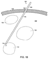
図1A、図1B、及び図1Cは、言語中枢部分103を持つ脳組織102内への展開中の本技術の一実施例に従って形成されたカテーテル導入システム100を示す。図1Aに示すように、カテーテル導入システム100は、頭蓋骨108の開口部106を通して脳組織102内に挿入され、脳組織を通る経路110に沿ってターゲット領域112まで前進するカニューレ104を含む。経路110に沿ったカニューレ104の前進を容易にするため、栓塞子114を使用してもよい。栓塞子114は、例えば、カニューレ104内に位置決めされてもよく、栓塞子の丸みのあるチップがカニューレの遠位端を越えて僅かに突出している。丸みのあるチップは、栓塞子114及びカニューレ104の前進時に脳組織102を切り開くのに役立つ。別の態様では、栓塞子114の代わりに、カニューレ104の前進時にカテーテル導入システム100の他の部分をカニューレ104内に位置決めしてもよい。例えば、栓塞子114の代わりに、脳組織102を切り開くのに適した遠位端を持つカテーテル(図示せず)を使用してもよい。
1A, 1B, and 1C illustrate a
カニューレ104は、直線状部分116及び遠位端の角形成部材118を含む。直線状部分116は実質的に剛性である。脳組織102を通る経路110が実質的に拘束されていないため、カニューレ104の直線状部分116の剛性構造は、カテーテル導入システム100の他の部分を所定位置に保持するのを補助する。本技術の幾つかの実施例では、カニューレ104の直線状部分116等のカニューレの剛性部分は、患者の頭蓋骨に固定的に取り付けられたカテーテル導入口内に拘束される。例えば、カニューレ104の直線状部分116は、カテーテル導入口の剛性スリーブにぴったりと受け入れられていてもよい。カニューレ104の直線状部分116が脳組織102内に位置決めされた後、直線状部分116の軸線方向移動を一時停止できる。例えば、本技術の幾つかの実施例に従って形成されたカテーテル導入口は、カニューレ104の直線状部分116が脳組織102内に位置決めされた後、直線状部分116の側壁と係合するように形成された、圧力ねじ等の係止機構を含んでいてもよい。本技術の幾つかの実施例に従って形成されたカテーテル導入口に関するこの他の詳細を以下に説明する。
角形成部材118は、直線状部分116の長さよりも遥かに短い。本技術の幾つかの実施例では、角形成部材118の長さは、その直径の約2倍乃至約15倍であり、例えばその直径の約3倍乃至約10倍である。しかしながら、他の実施例では、角形成部材118は別の形態を備えていてもよい。経路110に沿って前進するとき、角形成部材118は実質的に直線状である。図1Bに示すように、ターゲット領域112に達したとき、角形成部材118を賦勢し、コンパクトな角を形成する。この賦勢は、幾つかの機構のうちの一つに従って行うことができる。例示のカテーテル導入システム100では、角形成部材118は、所望の角度にプリテンションを加えたばねを含む。ばねは、可撓性ポリマーに封入されている。実質的に剛性の栓塞子114が角形成部材118内に位置決めされている場合には、角形成部材118は実質的に直線状形態に押圧されている。
The
図1Bに示すように、ターゲット領域112に達したとき、栓塞子114を越えてカニューレ104を前進でき、これにより角形成部材118はその弛緩形態を取り戻す。栓塞子114を部分的に又は完全に引き抜くことにより、角形成部材118にその弛緩形態を取り戻させる。特定の脳神経外科手術計画を実行するための任意の所望のプリテンション角度を持つ角形成部材118を、カニューレ104の直線状部分116の遠位端に手術前に装填してもよい。別の態様では、本技術の幾つかの実施例に従って形成された脳神経外科手術キットに、様々なプリテンション角度(例えば15°、30°、及び45°)の角形成部材118が設けられた一組のカニューレ104が含まれていてもよい。脳神経外科医は、特定の脳神経外科手術計画を実行するため、カニューレのセットから適当なカニューレ104を選択できる。
As shown in FIG. 1B, when the
図1Cに示すように、角形成部材118がその弛緩形態を取り戻した後、栓塞子114を完全に引き抜く。栓塞子114の代わりにカテーテル120をカニューレ104に挿入する。カテーテル120は、ターゲット領域内で優れた機動性を有する。カテーテル120は角形成部材118の所定の角度でカニューレ104を出る。カテーテル120は回転自在であり、血管カテーテル導入法について当該技術分野で周知の操向機構に従って蛇行するように操向できる。ターゲット領域112内では、単一の経路への移動の制限は、ターゲット領域外程重大ではない。従って、カテーテル120は、ターゲット領域112の所望の治療を行うのに必要であるように中間位置を通って移動できる。以下に説明するように、本技術のこの他の実施例には、様々なカテーテル形態が含まれ、二つ又はそれ以上の関節連結部及び関節を持つカテーテルが含まれる。
As shown in FIG. 1C, after the
図2A乃至図2Dは、本技術の別の実施例に従って形成されたカテーテル導入システム150を示す。図2A乃至図2Dのカテーテル導入システム150は、図1A、図1B、及び図1Cのカテーテル導入システム100よりも高度に関節連結されており、非線形経路に沿って脳組織102内に、図1A、図1B、及び図1Cに示すターゲット領域112とは異なる位置のターゲット領域152まで展開した状態で示してある。非線形経路は、実質的に直線状の第1部分154及び実質的に直線状の第2部分156を含み、実質的に直線状の第1部分及び実質的に直線状の第2部分が所定の角度をなす。非線形経路の実質的に直線状の第1部分154に沿ったカニューレ104の前進を容易にするため、図1Aに示す栓塞子114よりも僅かに細く且つ実質的に可撓性が高い栓塞子158を使用する。
2A-2D illustrate a
図2Bに示すように、方向転換を行うのが望ましい非線形経路の一部に達したとき、角形成部材160を賦勢し、コンパクトな角を形成する。図1A、図1B、及び図1Cに示す角形成部材118とは異なり、角形成部材160の賦勢は、血管カテーテル導入法について当該技術分野で周知の引っ張りワイヤ操向機構による引っ張りワイヤを使用して行われる。別の態様では、角形成部材160にプリテンションが加えられており、図1A、図1B、及び図1Cに示す角形成部材118に関して上文中に説明したプロセスと同様のプロセスに従って賦勢されてもよい。同様に、引っ張りワイヤ操向機構を使用して図1A、図1B、及び図1Cに示す角形成部材118を賦勢してもよい。栓塞子158は、角形成部材160の角と形態を一致するのに十分に可撓性である。次いで、図2Cに示すように、第2カニューレ162及び栓塞子158をカニューレ104を通して前進し、非線形経路の実質的に直線状の第2部分156に沿って延ばす。カニューレ104と同様に、第2カニューレ162は、直線状部分164及びその遠位端に設けられた角形成部材166を含む。カニューレ104とは異なり、第2カニューレ162の直線状部分164は、第1カニューレ104の角形成部材160を通過できるのに十分に可撓性である。
As shown in FIG. 2B, when a portion of the non-linear path where it is desirable to change direction is reached, the
第2カニューレ162がターゲット領域152に達したとき、第2カニューレ162の角形成部材166を賦勢し、別のコンパクトな角を形成できる。例えば、角形成部材166には、プリテンションが加えられていてもよいし、引っ張りワイヤ操向機構を使用して賦勢してもよい。カニューレ104を通して、第2カニューレ162を通して、及びターゲット領域152内にカテーテル168を前進する。カテーテル168は、角形成部材166を所定の角度で出る。カテーテル168には、その遠位部分172の位置を制御するため、関節170が設けられている。角形成部材160、166とは異なり、関節170は、カテーテル168を単一の経路に沿った移動に限定しない。関節170を図2Dに約45°の角度に賦勢した状態で示す。関節は、カテーテル168の遠位部分172がターゲット領域152の全ての部分にアクセスできるのに十分な可動範囲を備えていてもよい。例えば、関節170の可動範囲は、約120°乃至約180°であってもよい。図2Dでは、関節170は、カテーテル168の遠位部分172が、角形成部材166に直ぐ近くのターゲット領域152の部分にアクセスできるのに十分な可動範囲を備えていてもよい。
When the
カテーテル168は、角形成部材166よりも可撓性が高い。上文中に論じたように、第2カニューレ162の直線状部分164は、第1カニューレ104の角形成部材160を通過できるのに十分可撓性である。更に、角形成部材166は、角形成部材166が賦勢されていない場合、第1カニューレ104の角形成部材160を通過するのに十分可撓性である。角形成部材166を賦勢することにより、角形成部材166を比較的剛性にできる。組み合わせにおいて、賦勢した角形成部材166及び第2カニューレ162の直線状部分164は、カテーテル168がターゲット領域152内で移動するとき、脳組織102内でのそれらの位置を維持するのに十分に剛性であってもよい。
The
本技術の幾つかの実施例は、図1A、図1B、及び図1C、及び図2A乃至図2Dに示すカテーテル導入システム100、150の変形例を含む。例えば、幾つかの実施例は、一つ以上の角を持つ経路を形成するため、多数のカニューレを含む。追加のカニューレは、例えば、図2A乃至図2Dに示す第2カニューレ162と同様に展開できる。本技術の幾つかの実施例に従って形成された、関節連結された、又は入れ子式のエレメント、デバイス、及びシステムの数を増やすことにより、制約された方法で、CNS組織を通る実際上どのような経路も移動できる。本技術の幾つかの実施例に従って形成されたカニューレは、ナビゲーションを容易にするため、放射線不透過性マーカーが設けられた部分を含む。例えば、カニューレの直線状部分又は角形成部材に、これらの直線状部分又は角形成部材の長さの一部に沿って延びる細長い放射線不透過性マーカーが設けられていてもよい。本技術の幾つかの実施例では、リング形状又は部分リング形状の放射線不透過性マーカーが、角形成部材の開口部に、又はその一端又は両端に位置決めされる。
Some embodiments of the present technology include variations of the
多数のカニューレ間の相互作用は、図2A乃至図2Dに示すカニューレ104と第2カニューレ162との間の相互作用と異なっていてもよい。例えば、第2カニューレ162を第1カニューレ104の外側に位置決めし、図2A、図2B、及び図2Cに示す栓塞子158よりも僅かに太い栓塞子を使用してカテーテル導入経路の実質的に直線状の第2部分に沿って前進させてもよい。可撓性栓塞子の代わりに、本技術の幾つかの実施例で使用された栓塞子は、本体から取り外し自在の実質的に剛性のヘッドを備えていてもよい。カニューレの角及び経路を通してヘッドを押すため、実質的に剛性の本体を通って可撓性部分が延びていてもよい。このような栓塞子は、例えば、図2A乃至図2Dに示すカテーテル導入システム150で使用できる。非線形経路の実質的に直線状の第1部分の端部に達したとき、ヘッドを遠隔操作で取り外すことができる。次いで、ヘッドは、ターゲット領域に達するまで、非線形経路の実質的に直線状の第2部分156に沿って第2カニューレ162とともに移動できる。次いで、ヘッドを栓塞子の残りの部分に連結する可撓性部材によって、ヘッドを遠隔操作で引き抜くことができる。
The interaction between multiple cannulas may be different than the interaction between
本技術の幾つかの実施例は、様々な組成及び大きさのカニューレ、カテーテル、及び他のエレメントを含んでいてもよい。図1A、図1B、及び図1Cに示すカニューレ104の直線状部分116等の実質的に剛性のエレメントに適した材料には、ステンレス鋼及び硬質ポリマーが含まれる。図2C及び図2Dに示す第2カニューレ162の組成は、可撓性及び圧壊抵抗を提供するため、ポリマーで包んだ編製材料(例えば編製金属ワイヤ)等の強化構造を含んでいてもよい。本技術の幾つかの実施例のエレメントについて、比較的小径であるのが好ましいこれは、小径であると、カテーテル導入経路に沿ったCNS組織の妨害が少なくなるためである。本技術の幾つかの実施例に従って形成されたデバイス及びシステムのカニューレ又はカテーテルの大きさは、約3フレンチ乃至約20フレンチ(約1mm乃至約6.67mm)であり、例えば約5フレンチ乃至約14フレンチ(約1.67mm乃至約4.67mm)である。
Some embodiments of the technology may include cannulas, catheters, and other elements of various compositions and sizes. Suitable materials for the substantially rigid element, such as the
2.カテーテル導入口
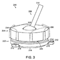
本技術の幾つかの実施例に従って形成されたデバイス及びシステムは、迅速に、正確に、安全に、及び低侵襲性で経頭蓋アクセスを行うように形成された、頭蓋骨マウント等のカテーテル導入口を含んでいてもよい。図3乃至図8は、本技術の一実施例に従って形成された頭蓋骨マウント200及びその部分を示す。頭蓋骨マウント200は、ベース202、キャップ204、及び調節自在の導入口206を含む。図3及び図4に示すように、調節自在の導入口206は、球状部分208及び方向部分210を含む。球状部分208は、調節自在の導入口206を特定の位置に係止するため、ベース202とキャップ204との間に捕捉される。球形自在継手と同様に、球状部分208をベース202とキャップ204との間に係止する前に、方向部分210の角度及び半径方向位置を定めるように球状部分の位置を調節できる。方向部分210をこれ以上傾けることができないようにキャップ204がブロックする角度が最大角度である。頭蓋骨マウント200では、最大角度は約30°である。本技術の幾つかの実施例に従って形成された変形例のカテーテル導入口は、調節自在の導入口と固定部分との間の半径方向移動範囲がこれよりも大きくてもよいし、小さくてもよい。
2. Catheter Inlet A device and system formed in accordance with some embodiments of the present technology is a catheter, such as a skull mount, that is configured for rapid, accurate, safe, and minimally invasive transcranial access. An inlet may be included. 3-8 illustrate a
頭蓋骨マウント200により、特定の脳内進入角度を持つ脳神経外科手術計画を実行できる。更に、頭蓋骨マウント200は、脳神経外科手術計画の仕様に従って頭皮の任意の部分に位置決めできる。図5及び図6に示すように、ベース202は、ベースの本体214に一体蝶番216で連結された三つの取り付けタブ212を含む。一体蝶番216は、可撓性プラスチック(例えば、ポリエチレン又はポリプロピレン)で形成されていてもよい。例示の頭蓋骨マウント200では、取り付けタブ212は、直径3mmの骨ねじを受け入れる大きさを備えている。一体蝶番216は、ベース202の形態を頭皮表面の凹凸と一致するのに役立つ。頭蓋骨マウント200は、更に、ベース202の本体214の底面のガスケット凹所内に位置決めされるガスケット218を含む。ガスケット218は、ベース202と頭皮の凹凸のある表面との間に水密シールを形成するのに十分なだけ、形態を一致できる。
The
図6に示すように、ベース202の本体214は、頭皮表面と調節自在の導入口206の球状部分208との間に位置決めされるように形成されたチャンバ222を含む。本体214は、入口導管224及び出口導管226を含む。作動では、入口導管224及び出口導管226に入口パイプ(図示せず)及び出口パイプ(図示せず)を夫々連結できる。入口パイプ及び出口パイプは、チャンバ222を連続的に又は断続的にフラッシングするように形成されていてもよい。例えば、入口導管224を通してフラッシング液(例えば生理食塩水)を導入でき、出口導管226を通して除去できる。このようなフラッシングは、頭蓋骨開口部を清浄にし感染症を防ぐのに役立つ。フラッシング流体の流れを制御するため、又はチャンバ222を必要に応じてシールし又はシール解除するため、バルブが設けられていてもよい。感染症の危険を小さくするための別の特徴として、頭蓋骨マウント200は使い捨てであってもよい。例えば、頭蓋骨マウント200は、主として安価な硬質プラスチックで形成されていてもよい。使い捨てでない場合には、頭蓋骨マウント200の部分は、例えばオートクレーブで完全に殺菌されるように形成できる。
As shown in FIG. 6, the
図7及び図8は、頭蓋骨マウント200のキャップ204を示す。キャップ204をベース202に係止するため、ベースの雄ねじ部分228がキャップ204の雌ねじ部分230と相互係止するようにキャップ204を回転できる。雄ねじ部分228及び雌ねじ部分230のねじ山は台形のアクメ形状である。調節自在の導入口206が頭蓋骨マウント200内に位置決めされたとき、キャップ204をベース202に螺着することによる圧力によりキャップのクランプ面232を調節自在の導入口の球状部分208に押し付け、これにより、ベースの座236に位置決めしたO−リング234に球状部分を押し込む。図8に示すように、クランプ面232は、調節自在の導入口206の球状部分208の湾曲と一致する湾曲を持つ凹状である。球状部分208とO−リング234との間、O−リングと座236との間、及び球状部分208とクランプ面232との間の摩擦は、調節自在の導入口206を頭蓋骨マウント200内の特定の位置に係止するのに役立つ。図7に示すように、キャップ204は、キャップをベース202に係止するときにキャップを握り易くする押縁238を含む。
7 and 8 show the
本技術の幾つかの実施例に従って形成された頭蓋骨マウント200の使用には、ベース202及びガスケット218を患者の頭皮の選択された部位に置く工程と、取り付けタブ212のねじ穴にねじを挿入する工程とが含まれる。次いで、計画されたカテーテル導入経路の第1部分の方向に方向部分210を向け、調節自在の導入口206及びキャップ204をベース202に固定できる。次いで、脳に導入されるべきカニューレ又はカテーテルよりも僅かに大径の又はこれとほぼ同じ直径のドリル部材を持つドリルを使用し、頭蓋骨に開口部をドリル穿孔する。ドリル穿孔後、調節自在の導入口206及びキャップ204を取り外し、開口部の部位から骨片を完全に払拭する。別の態様では、上文中に説明したフラッシング機構を使用して部位を清浄にしてもよい。硬膜を分離するため、又は開口部の下の硬化した硬膜を押し潰すため、手動工具を使用してもよい。本技術の幾つかの実施例に従って形成されたシステムは、システムのカニューレ又はカテーテルを挿入するための適当な直径の開口部を形成するように形成されたこのような手動工具並びにドリル又はドリルビットを含んでいてもよい。
Use of a
頭蓋骨に開口部を形成するために調節自在の導入口206及びキャップ204を取り外す場合には、キャップに対する調節自在の導入口の位置を再現できる。別の態様では、調節自在の導入口206及びキャップ204を取り外す前に導入口及びキャップを互いに対して固定(例えばエポキシ接着剤を使用して)してもよく、この場合、頭蓋骨に開口部を形成した後、導入口及びキャップを固定形態のベースに再固定する。頭蓋骨開口部の形成後、調節自在の導入口206を介してカニューレ又はカテーテルを脳に導入できる。本技術の幾つかの実施例に従って形成されたカテーテル導入口では、調節自在の一つの導入口(例えば調節自在の導入口206)は、ドリル穿孔を行うために含まれており、カテーテル導入を行うため、調節自在の第2導入口が含まれる。調節自在の第2導入口は、カテーテル導入を容易にする特徴、逆流を阻止するためのテューイボーストアダプタ等を含んでいてもよい。更に、調節自在の第2導入口は、カテーテルの意図せぬ移動を阻止するように形成されていてもよい。例えば、調節自在の第2導入口は、カテーテルと摩擦係合し、カテーテルを任意の方向(例えば軸線方向、横方向、又は半径方向)に移動するのに必要な力の閾値を増大する。
When the
本技術の幾つかの実施例に従って形成されたカテーテル導入口は、オペレータが患者の頭部からかなり離れた場所に居る場合に、オペレータがカニューレ又はカテーテルを操作できるように形成されていてもよい。これは、手術中に使用されるデータ収集システム(例えばX線透視システム)からの放射線に対するオペレータの被爆を最少にするのに有用である。本技術の幾つかの実施例では、オペレータは、患者の頭部から約0.5m乃至約5m、例えば約1m乃至約3mのところに居るときにカニューレ又はカテーテルを操作できる。脳神経外科手術では、カテーテル導入経路の周囲の組織を損傷しないため、カニューレ又はカテーテルがCNS組織内で不時に移動しないようにすることが重要である。細長い剛性の導入口(例えば、調節自在の導入口206の方向部分210)とCNS組織内に延びるカニューレ又はカテーテルの一部との間の相互作用は、このような不時の移動を阻止する上で有用である。例えば、カニューレ又はカテーテルが方向部分の長さに沿って前後方向以外の方向に移動しないようにするため、カニューレ又はカテーテルの剛性の又は可撓性の部分を、頭蓋骨マウント200の方向部分210にぴったりと嵌着できる。本技術の幾つかの実施例に従って形成された頭蓋骨マウントの方向部分の長さは、方向部分の内腔の直径の約5倍乃至約100倍であってもよく、例えば約10倍乃至約50倍であってもよい。
A catheter inlet formed in accordance with some embodiments of the present technology may be configured to allow an operator to manipulate a cannula or catheter when the operator is located far away from the patient's head. This is useful for minimizing operator exposure to radiation from data acquisition systems (eg, fluoroscopy systems) used during surgery. In some embodiments of the present technology, the operator can manipulate the cannula or catheter when they are about 0.5 m to about 5 m, such as about 1 m to about 3 m from the patient's head. In neurosurgery, it is important to prevent the cannula or catheter from moving inadvertently within the CNS tissue, as it does not damage the tissue surrounding the catheter introduction pathway. The interaction between the elongated rigid inlet (eg, the
本技術の幾つかの実施例に従って形成されたカテーテル導入口は、図3乃至図8を参照して上文中に開示した特徴の他に様々な特徴を備えていてもよい。例えば、カテーテル導入口は、X線に対して実質的に透明であってもよく、又はナビゲーションを容易にするための一つ又はそれ以上の放射線不透過性マーカーを除いてX線に対して実質的に透明であってもよい。放射線不透過性マーカーは、例えば、細長い導入口(例えば、頭蓋骨マウント200の方向部分210)の方向を示すために設けられていてもよい。本技術の幾つかの実施例に従って形成されたカテーテル導入口は、更に、超音波検査システムの一部を含んでいてもよい。以下に更に詳細に説明するように、超音波検査法は、本技術の幾つかの実施例に従ってカニューレ又はカテーテルをCNS組織内でナビゲートするのに使用できる。カニューレ又はカテーテルを監視するため、又はカニューレ又はカテーテルに設けられた対応する超音波検査エレメントと相互作用するため、超音波トランスジューサ又は超音波トランスジューサのアレイがカテーテル導入口に位置決めされていてもよい。例えば、カテーテル導入口は、細長い導入口(例えば、頭蓋骨マウント200の方向部分210)と整合した超音波トランスジューサを含んでいてもよい。超音波トランスジューサは、細長い導入口の一部に位置決めされていてもよく、又は細長い導入口の方向と一致するように調節できる別体の構造に位置決めされていてもよい。カテーテル導入口は、更に、CNS組織内のカニューレ又はカテーテルの一部に設けられた対応する超音波検査エレメントに向かって延びるように、手動で又は自動で調節できる超音波トランスジューサを含んでいてもよい。例えば、超音波トランスジューサは、手動又は自動の制御システムに応答する機械的アクチュエータ又は磁気アクチュエータを持つマウントに位置決めされていてもよい。自動制御システムは、Aモード超音波データからの近接検出等の超音波データ演算処理装置を含んでいてもよい。本技術の幾つかの実施例に従って形成されたカテーテル導入口の超音波トランスジューサは、距離を計測する、又は撮影を行うように形成されていてもよい。例えば、本技術の幾つかの実施例に従って形成されたカテーテル導入口は、Mモード超音波データを収集するように形成された超音波トランスジューサを含む。
A catheter inlet formed in accordance with some embodiments of the present technology may have various features in addition to those disclosed above with reference to FIGS. For example, the catheter inlet may be substantially transparent to X-rays or substantially transparent to X-rays except for one or more radiopaque markers to facilitate navigation. May be transparent. A radiopaque marker may be provided, for example, to indicate the direction of the elongated inlet (eg, the
3.カテーテル特徴
本技術の幾つかの実施例に従って形成されたカテーテルは、CNS内のターゲット領域を治療するための機能的構造を備えていてもよい。例えば、このようなカテーテルの遠位部分は、周囲組織への損傷を最少にして材料を除去するように形成されていてもよい。これは、健康な組織で発生する凝血塊を除去するのに特に有用である。周囲組織は、例えば、凝血塊を激しくちぎり取る又は引っ張ることによって損傷する。除去対象の凝血塊は、カテーテルと比べて比較的大きいことが多い。カテーテルの外部で凝血塊を切り分けるには激しい機械的作用が必要とされ、これは、周囲組織を損傷するおそれがある。凝血塊の表面は、多くの場合、一体性が高く、そのため、無傷の凝血塊表面に吸引作用を加えると、凝血塊を必要なだけ破壊して除去可能な小片にせずに凝血塊を過度に引っ張るおそれがある。このような方法とは異なり、本技術の幾つかの実施例に従って形成されたカテーテルは、例えば、カテーテルの内腔近くの、又はカテーテルの内腔内に突出した対象物の部分を切り離すことによって、対象物の表面を注意深く破壊する。別の態様では、又はこれに加えて、カテーテルは、別の形態の機械的作用(例えば、カテーテル内腔内に又はカテーテルの僅かに外側に加えられた作用)を使用して対象物の表面を破壊するように形成されていてもよい。凝血塊の材料は、例えば、通常は、破壊された表面を通して最少量の吸引力でカテーテルに吸い込まれる。
3. Catheter Features Catheters formed in accordance with some embodiments of the present technology may include a functional structure for treating a target area in the CNS. For example, the distal portion of such a catheter may be configured to remove material with minimal damage to surrounding tissue. This is particularly useful for removing clots that occur in healthy tissue. The surrounding tissue is damaged, for example, by severely tearing or pulling the clot. The clot to be removed is often relatively large compared to the catheter. Severing the clot outside the catheter requires intense mechanical action, which can damage the surrounding tissue. The clot surface is often highly integrated, so applying a suction action to the intact clot surface will cause the clot to be excessively destroyed without breaking it into necessary pieces. There is a risk of pulling. Unlike such methods, catheters formed in accordance with some embodiments of the present technology can be used, for example, by cutting off portions of an object near or protruding into the lumen of the catheter. Carefully destroy the surface of the object. In another aspect, or in addition, the catheter may use another form of mechanical action (eg, action applied within the catheter lumen or slightly outside the catheter) to clean the surface of the object. You may form so that it may destroy. The clot material is typically drawn into the catheter with a minimal amount of suction through the fractured surface, for example.
図9乃至図10Bは、本技術の幾つかの実施例に従って形成された、対象物(例えば凝血塊)の部分を切り離すのに特に適したカテーテル遠位部分を示す。しかしながら、これらの実施例は、他の機能のうちの別の形態の機械的作用を使用して対象物の表面を破壊するのにも使用できる。例えば、図9は、内腔を少なくとも部分的に形成するカテーテル遠位部分300を示す。表面破壊器即ち表面ディスラプタ(disrupter) 304がドライバー306の遠位端のところで内腔内に位置決めされている。ドライバー306は可撓性であり、カテーテルを通って、カテーテルの近位端の先の手動アクチュエータ又は自動アクチュエータ(図示せず)まで延びている。例示の実施例の表面ディスラプタ304は、尖っていない丸みのある遠位端及び近位側のリング形状切断エッジを持つ実質的に剛性のカップ形状カッターの形態を備えている。本体302は、横方向開口部308及び端部開口部310を含む。この他の実施例では、端部開口部が無くてもよく、横方向開口部が無くてもよく、又は2個、3個、又はそれ以上の横方向開口部が設けられていてもよい。ドライバー306は、表面ディスラプタ304を横方向開口部308及び端部開口部310に対して移動するように形成されており、又は表面ディスラプタを回転するように形成されている。
9-10B illustrate a distal catheter portion that is particularly suitable for severing a portion of an object (eg, a clot) formed in accordance with some embodiments of the present technology. However, these embodiments can also be used to destroy the surface of an object using another form of mechanical action among other functions. For example, FIG. 9 shows a catheter
作動では、除去対象(例えば凝血塊)が横方向開口部308又は端部開口部310の近くにあるようにカテーテル遠位部分300を位置決めできる。吸引力を加え、対象物の一部を横方向開口部308又は端部開口部310に引き込む。ドライバー306は、表面ディスラプタ304をカテーテル遠位部分300の長さに沿って移動でき、又は表面ディスラプタ304を回転し、対象物の一部を切り離し、又は他の態様で対象物の表面を破壊する。接触は内腔内で生じ(例えば、吸引力を使用して対象物の表面を横方向開口部308又は端部開口部310に引き込む場合)、又は内腔外で、例えば遠位端の僅かに外で生じる。ドライバー306は、表面ディスラプタ304を対象物に押し込むか或いは表面ディスラプタを僅かに回転し、対象物の表面を破壊する。対象物の表面を破壊した後、ドライバー306によって表面ディスラプタ304を引き込むことができる。次いで、吸引力を加え、対象物の材料を対象物の破壊された表面及び横方向開口部308又は端部開口部310を通して内腔に引き込む。除去対象から材料が内腔に引き込まれると、代表的には、周囲組織を損傷することなく材料を細断でき、又は比較的強く移動できる。例えば、表面ディスラプタ304は、材料を内腔内で押したり引いたりするのにも使用できる。更に、表面ディスラプタ304は、材料がカテーテルに吸い込まれるときに比較的高速で回転できる。材料をこのように細断することは、強い吸引力を使用せずに材料をカテーテルの残りの長さに亘って移動するのを容易にする上で有用である。
In operation, the catheter
図9に示すカテーテル遠位部分300では、表面ディスラプタ304は、丸みのある遠位部分及び直線状の近位部分を有する。他の実施例では、表面ディスラプタ304は逆の構造を備えていてもよく、丸みのある近位部分及び直線状の遠位部分を備えていてもよい。更に、表面ディスラプタ304を、遠位チップを持つ弾丸形状表面ディスラプタ等の別の種類の表面ディスラプタに代えてもよい。図10A及び図10Bは、部分チューブの形態の表面ディスラプタ352を含むカテーテル遠位部分350の他の実施例を示す。表面ディスラプタ352は、横方向開口部308とほぼ一致する形態の切断面354を含む。対象物(例えば凝血塊)を内腔に引き込むために吸引力が加えられたとき、ドライバー306が表面ディスラプタ352を移動し、対象物から材料を切り離す。表面ディスラプタ352の遠位端は開放している。変形例では、材料(例えば生体検査組織)を表面ディスラプタ内に捕捉するように、表面ディスラプタ352の遠位端は、閉鎖されていてもよい。変形例では、材料を捕捉した後、表面ディスラプタ352を引き込むことができる。表面ディスラプタ352は、再挿入前に清浄にされる。図9乃至図10Bに示す表面ディスラプタ304、352は、カテーテル遠位部分300、350の内腔の内径のほぼ全体を占有する。別の態様では、表面ディスラプタ304、352は、カテーテル遠位部分300、350の内腔の内径よりも小さくてもよい。
In the catheter
図11乃至図12Bは、本技術の幾つかの実施例に従って形成された、穏やかな機械的作用を使用して対象物表面(例えば凝血塊表面)を破壊するのに特に適したカテーテル遠位端を示す。しかしながら、これらの実施例は、他の機能のうち、対象物の部分を切り離すのにも使用できる。例えば、図11は、多数の円弧状ワイヤを含む表面ディスラプタ402を含むカテーテル遠位部分400を示す。表面ディスラプタ402は、エッグビーター即ち泡立て器と似ている。表面ディスラプタ402が内腔に引き込まれないようにするため、遠位端の近くの内腔内にストップ404が設けられている。カテーテル遠位部分400の本体406には横方向開口部が設けられていない。幾つかの変形例では、表面ディスラプタ402は、カテーテル遠位部分400の遠位端にしっかりと固定されていてもよく、又は全体をカテーテル遠位部分に自由に引っ込めることができてもよい。幾つかの変形例では、表面ディスラプタ402は、少なくとも部分的に、組織に吸引力が直接加わらないように保護するのに役立ち、又はカテーテル遠位部分400の縁部から組織を保護するのに役立つ。これらの及びその他の実施例では、ドライバー306が省略されていてもよく、カテーテル遠位部分400の移動を使用して表面ディスラプタ402を対象物内に打ち込んでもよい。
FIGS. 11-12B illustrate a catheter distal end that is particularly suitable for destroying an object surface (eg, a clot surface) using gentle mechanical action formed in accordance with some embodiments of the present technology. Indicates. However, these embodiments can also be used to separate parts of objects among other functions. For example, FIG. 11 shows a catheter
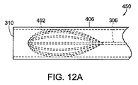
多くの脳神経外科手術の用途において、カテーテル導入経路に沿った組織に対する損傷を最少にするため、最小直径のカテーテルを前進するのが望ましい。しかしながら、カテーテルの直径よりも大きな構造は、ターゲット領域で治療を行う上で有用である。例えば、ターゲット領域での治療には、カテーテルの遠位部分よりも遥かに大きい対象物を除去することが必要とされる。拡張構造により、カテーテルの直径を拡大することなく、このような治療を容易に行うことができる。図12A及び図12Bは、内腔を出た後に拡張する表面ディスラプタ452を含むカテーテル遠位部分450を示す。図12Aは、延長及び拡張前のコンパクトな形態の表面ディスラプタ452を示す。図12Bは、延長後の拡張形態の表面ディスラプタ452を示す。拡張形態は、表面ディスラプタ452の弛緩形状である。図11乃至図12Bに示すカテーテル遠位部分400、450の例示の実施例では、表面ディスラプタ402、452に含まれるワイヤの数は、これよりも多くても少なくてもよい。更に、対象物の表面を更に激しく破壊するため、ワイヤの代わりに、鋭い縁部を持つリボン構造等の他の細長い構造を使用してもよい。更に、表面ディスラプタを比較的穏やかにするように、表面ディスラプタ402、452全体に亘って、又はその一部に亘って可撓性メンブレンが延びていてもよい。
In many neurosurgical applications, it is desirable to advance the smallest diameter catheter in order to minimize damage to the tissue along the catheter delivery path. However, structures larger than the diameter of the catheter are useful for performing treatment at the target area. For example, treatment at the target area requires removal of an object that is much larger than the distal portion of the catheter. Due to the expanded structure, such treatment can be easily performed without enlarging the diameter of the catheter. 12A and 12B show a catheter
本技術の幾つかの実施例に従って形成されたカテーテル遠位部分は、内腔に入った材料の除去を容易にする構造を備えていてもよい。例えば、図13、図14、及び図15は、他の機能のうち、対象物表面の破壊に適した変形例の構造と組み合わせた構造を持つ、本技術の幾つかの実施例に従って形成されたカテーテル遠位部分を示す。図13は、捩じれ刃ドリルビットと同様の螺旋溝506を持つ細長い細断器504の端部に表面ディスラプタ502が設けられた、カテーテル遠位部分500を示す。表面ディスラプタ502は、研磨パターンを備えている。細長い細断器504は、図9乃至図12Bに示すドライバー306よりも大径である。螺旋溝506は、細長い細断器504の回転時に材料の細断を補助し、内腔を通して材料を移動するスクリューコンベアとして作用する。カテーテル導入経路に沿った角を通して前進できるようにするため、細長い細断器504は、可撓性であってもよく、又は図9乃至図12Bに示すドライバー306と同様の小径のドライバーにテーパ等で移行する前にカテーテル遠位部分500の長さに沿って短い距離に亘って延びていてもよい。細長い細断器504は、軸線方向移動又は回転移動をドライバーから表面ディスラプタ502に伝達できる。研磨パターン503は、特定の治療用途の要件と対応する所定程度の粗さ(例えば砂粒等)を備えていてもよい。例えば型成形プロセスを使用し、様々な程度の粗さを持つ研磨パターン503を形成してもよい。
The distal catheter portion formed in accordance with some embodiments of the present technology may include a structure that facilitates removal of material that has entered the lumen. For example, FIGS. 13, 14 and 15 were formed in accordance with some embodiments of the present technology having a structure combined with, among other functions, a modified structure suitable for destroying an object surface. The distal portion of the catheter is shown. FIG. 13 shows a catheter
図14は、アルキメデスのねじを含む細長い細断器552を含むカテーテル遠位部分550を示す。細長い細断器552の端部分554は、カテーテル遠位部分550の遠位端を越えて僅かに延びている。作動では、カテーテル遠位部分550の長さに沿って細長い細断器552を移動でき、又は回転できる。端部分554は、カテーテル遠位部分550の遠位端近くの対象物の表面を破壊でき、従って、表面ディスラプタとして作用する。アルキメデスのねじは、細長い細断器552の回転時に材料の細断を補助し、内腔を通して材料を移動するスクリューコンベアとして作用する。アルキメデスのねじは、端部分554から遠ざかるにつれて直径がテーパしており、細長い細断器552は、最終的には、図9乃至図12Bに示すドライバー306と同様の小径のドライバーに移行する。
FIG. 14 shows a catheter
図15は、ワイヤ鞭の形態の細長い細断器602を含むカテーテル遠位部分600を示す。細長い細断器602の端部分604は、カテーテル遠位部分600の遠位端を越えて僅かに延びている。作動では、細長い細断器602をカテーテル遠位部分600の長さに沿って移動でき、又は回転できる。端部分604は、カテーテル遠位部分600の遠位端の近くの対象物の表面を破壊でき、従って表面ディスラプタとして作用する。細長い細断器602をカテーテル遠位部分600の内腔内で回転することにより、材料の細断を補助し、カテーテルを通して材料を搬送できる。別の態様では、回転に加え、細長い細断器602の一部又は全体を真っ直ぐにでき、弾性によりその螺旋形状に戻すことができる。細長い細断器602の近位部分を引っ張ることにより、この作用を行うことができる。図15には、細長い細断器602を、カテーテル遠位部分600の内腔のほぼ全内径を占める状態で示す。別の態様では、細長い細断器602は、カテーテル遠位部分600の内腔の内径の比較的小さな部分を占めてもよい。
FIG. 15 shows a catheter distal portion 600 that includes an
細長い細断器602は、可撓性であってもよく、カテーテル遠位部分600だけでなくカテーテルの長さの任意の部分の全体に沿って延びていてもよい。細長い細断器602は、可撓性であるため、カテーテル導入経路の角を通って移動できる。本技術の幾つかの実施例は、逆方向に回転するように形成された二つのワイヤ鞭等の一つ以上のワイヤ鞭を持つ細長い細断器を含む。変形例は、カテーテルの長さに沿って可撓性を保持する図15に示すワイヤ鞭以外の構造を持つ細長い細断器を含んでいてもよい。このような細長い細断器は、例えば、鋭い縁部を持つ、又は持たない螺旋状リボンを含んでいてもよい。このような構造の細断特徴(例えば、ワイヤ屈曲部又は鋭い縁部)は、連続していてもよいし、又はカテーテルの長さに沿った一つ又はそれ以上の位置に限定されてもよい。例えば、カテーテルの近位部分の近くには細断特徴がほとんどないのがよい。
The
本技術の幾つかの実施例に従って形成されたカテーテル遠位部分は、断続的に加えられる吸引力等を使用するように設計されていてもよい。吸引力は、例えば、カテーテル遠位部分の内腔全体を通して加えることができ、又はカテーテル遠位部分の内腔内の別の導管の内腔を通して加えることができる。図16Aは、主部分654及び回転自在のプラグ656を持つ吸引導管652を含むカテーテル遠位部分650を示す。カテーテル遠位部分650は、更に、小径のフラッシング導管658を含む。フラッシング導管658は、回転自在のプラグ656の横側に当接した端部開口部659を有する。吸引導管652の主部分654、吸引導管652の回転自在のプラグ656、及びフラッシング導管658が協働し、高度に制御された方法で吸引力を加えることができる。カテーテル遠位部分650の遠位端にはウィンドウ660が設けられている。回転自在のプラグ656は、遠位ウィンドウ662、横ウィンドウ664、及び近位ウィンドウ666を含む。吸引導管652の主部分654の遠位端には、第1ウィンドウ668及び第2ウィンドウ670が設けられている。図16Bは、ウィンドウ662、664、666、668、670を図16Aよりもはっきりと示す、吸引導管652の分解斜視図である。図9乃至図12Bに示すドライバー306と同様のドライバー(図示せず)が回転自在のプラグ656の近位端に連結されていてもよい。ドライバーは、回転自在のプラグを回転するため、吸引導管652の長さに沿って近位方向に延びている。
A catheter distal portion formed in accordance with some embodiments of the present technology may be designed to use intermittently applied suction or the like. The suction force can be applied, for example, through the entire lumen of the catheter distal portion, or through the lumen of another conduit within the lumen of the catheter distal portion. FIG. 16A shows a catheter
回転自在のプラグ656が図16A及び図16Bに示す第1位置にあるとき、(1)カテーテル遠位部分650のウィンドウ660及び回転自在のプラグの遠位ウィンドウ662が整合しており、(2)回転自在のプラグの横ウィンドウ664及びフラッシング導管658の端部開口部659は整合しておらず、(3)回転自在のプラグの近位ウィンドウ666は、主部分654の第1ウィンドウ668又は第2ウィンドウ670のいずれとも整合していない。この位置では、回転自在のプラグ656の内腔の負圧と対応する、制御された量の吸引力を材料(例えば凝血塊材料)に加え、回転自在のプラグの内腔に引き込むことができる。次いで、回転自在のプラグ656を90°回転し、第2位置にする。第2位置では、(1)カテーテル遠位部分650のウィンドウ660及び回転自在のプラグの遠位ウィンドウ662が整合しておらず、(2)回転自在のプラグの横ウィンドウ664及びフラッシング導管658の端部開口部659が整合しており、(3)回転自在のプラグの近位ウィンドウ666及び主部分654の第2ウィンドウ670が整合している。この位置では、主部分654に吸引力が加わり、材料を回転自在のプラグ656の内腔から回転自在のプラグの近位ウィンドウ666を通して、主部分654の第2ウィンドウ670を通して主部分654の内腔内に、カテーテルの長さに沿って引き込むことができる。更に、吸引力により、フラッシング材料(例えば水)をフラッシング導管658からフラッシング導管の端部開口部659を通して、回転自在のプラグ656の横ウィンドウ664を通して、回転自在のプラグの近位ウィンドウ666を通して、主部分654の第2ウィンドウ670を通して、主部分の内腔内にカテーテルの長さに沿って引き込むことができる。回転自在のプラグ656の内腔のフラッシング後、回転自在のプラグを90°回転し、第3位置にする。この位置では、(1)カテーテル遠位部分650のウィンドウ660及び回転自在のプラグの遠位ウィンドウ662は整合しておらず、(2)回転自在のプラグの横ウィンドウ664及びフラッシング導管658の端部開口部659は整合しておらず、(3)回転自在のプラグの近位ウィンドウ666及び主部分654の第1ウィンドウ668が整合している。この位置では、プロセスを繰り返す前に回転自在のプラグ656の内腔に吸引力を加えることができる。第2位置及び第3位置では、カテーテル遠位部分650のウィンドウ660及び回転自在のプラグの遠位ウィンドウ662が整合していないため、回転自在のプラグの内腔のフラッシングに使用される、回転自在のプラグの内腔に加えられる吸引力は比較的強い。
When the
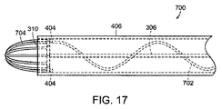
図9乃至図16Bに示す様々な構造は、本技術に従って形成されたカテーテルの追加の有用な実施例を形成するため、取り外し、追加し、組み合わせ、又はその他の態様で相互交換できる。例えば、様々な表面ディスラプタを様々な細長い細断器と組み合わせることができる。図17は、図15に示す細長い細断器602と同様の細長い細断器702及び図11に示す表面ディスラプタ402と同様の表面ディスラプタ704を含むカテーテル遠位部分700を示す。作動では、表面ディスラプタ704は、対象物(例えば凝血塊)の表面を破壊できる。次いで、対象物から材料をカテーテル遠位部分700の内腔に引き込み、細長い細断器702が材料を細断し、材料をカテーテルの内腔の残りに亘って吸引力によって移動することを容易にする。細長い細断器702は、カテーテル遠位部分700の遠位端を越えて僅かに延びるように形成されていてもよい。例えば、細長い細断器702は、表面ディスラプタ704内の領域まで延びるように形成されていてもよく、表面ディスラプタ704は、細長い細断器702がこれ以上延びないようにブロックできる。同様に、表面ディスラプタ304、352、452、502及び端部分554がカテーテル遠位部分の遠位端を越えて移動しないように制限するため、図9乃至図10B及び図12A乃至図14に示すカテーテル遠位部分300、350、450、500、550に、表面ディスラプタ704又は同様の構造が含まれていてもよい。例えば、表面ディスラプタ704又は同様の構造が、図9乃至図10B及び図12A乃至図14に示すカテーテル遠位部分300、350、450、500、550の遠位端に固定されていてもよい。
The various structures shown in FIGS. 9-16B can be removed, added, combined, or otherwise interchanged to form additional useful embodiments of catheters formed in accordance with the present technology. For example, various surface disrupters can be combined with various elongated shredders. FIG. 17 shows a catheter
本技術の幾つかの実施例による特に有利な組み合わせの一例では、表面ディスラプタ704又は同様の構造を図9に示すカテーテル遠位部分300の遠位端に固定した。表面ディスラプタ704は、表面ディスラプタ304の移動を制限し、材料(例えば凝血塊材料)を通して引き込むことができる篩として作用する。表面ディスラプタ304の尖った近位方向に向いた縁部は、表面ディスラプタ304を表面ディスラプタ704に対して軸線方向に移動するとき、表面ディスラプタ704の開口部(例えば、表面ディスラプタ704のワイヤ間)を通って延びる対象物から材料を切断できる。
In one example of a particularly advantageous combination according to some embodiments of the present technology, a
本技術の幾つかの実施例は、カテーテル制御アッセンブリを含む。このアッセンブリは、例えば、オペレータがナビゲーションや組織監視データに集中しているときに触感的作動を容易にする制御装置を含む手動コントローラを含んでいてもよい。図18は、本技術の一実施例に従って形成されたカテーテルコントローラ750を示す。カテーテルコントローラ750は、カテーテルを通る吸引力の賦勢に使用できる吸引力トリガー752を含む。外部吸引源(図示せず)が吸引導管754を通して吸引力を提供できる。吸引力トリガー752を押したとき、吸引力を賦勢することにより、吸引導管754とカテーテルの内腔との間のバルブを自動的に開放できる。吸引力トリガー752を離すと、バルブを自動的に閉鎖できる。このようにして、吸引力を別個の容積で断続的に加えることができる。作動では、対象物(例えば凝血塊)を減量するため、吸引力を連続的に加えることができ、次いで対象物の縁部を断続的に近付け、周囲組織を破壊しないように重大な注意を払うことができる。変形例は、様々なレベルの吸引力を持つ多数の吸引源を含んでいてもよい。例えば、カテーテルコントローラ750の吸引力トリガー752の代わりに、強力吸引導管に繋がるバルブを開放するように形成された強力吸引ボタン及び低吸引力導管に繋がるバルブを開放するように形成された低吸引力ボタンを使用してもよい。例えば、このような実施例により、図16A及び図16Bを参照して上文中に説明したように、材料を除去するための穏やかな吸引力及びカテーテルのフラッシングを行うための強力な吸引力を使用できる。
Some embodiments of the present technology include a catheter control assembly. The assembly may include, for example, a manual controller that includes a controller that facilitates tactile actuation when the operator is focused on navigation and tissue monitoring data. FIG. 18 illustrates a
カテーテルコントローラ750は、更に、細長い細断器の回転トリガー756及び細長い細断器の摺動トリガー758を含む。細長い細断器の回転トリガー756は、カテーテル内の細長い細断器を回転するように形成されていてもよい。細長い細断器の摺動トリガー758は、細長い細断器をカテーテルの長さに沿って軸線方向に移動するように形成されていてもよい。カテーテルコントローラ750内の機械的アクチュエータにより、細長い細断器の回転トリガー756及び細長い細断器の摺動トリガー758に応じて回転及び移動を行うことができる。別の態様では、手動で延ばすことによって、細長い細断器の回転又は軸線方向移動を手動で制御できる。更に、図11を参照して上文中に説明した表面ディスラプタ402等の本技術の幾つかの実施例に従って形成されたカテーテルの他の構造の回転又は移動を、クランク等で手動で行うことができる。細長い細断器の回転及び移動は、カテーテルの内腔が詰まらないように必要に応じて使用できる。変形例では細長い細断器の回転トリガー756及び細長い細断器の摺動トリガー758の代りに、又はこれらのトリガーに加えて、カテーテル内の他の構造用の他の作動トリガーを設けてもよい。例えばハンドコントローラ750を、図16A及び図16Bを参照して上文中に説明した吸引導管652を持つカテーテルで使用してもよく、回転自在のプラグ656を例えば90°増分で回転するためのトリガーがハンドコントローラに設けられていてもよい。
The
カテーテルコントローラ750に設けられた第1カテーテル関節制御装置760及び第2カテーテル関節制御装置762の各々は、図2Dを参照して上文中に説明した関節170等のカテーテルの関節の角度を制御する。他の実施例では、カテーテルの関節の数に応じて、関節制御装置が設けられていなくてもよく、関節制御装置が一つしか設けられていなくてもよく、又は二つ又はそれ以上の関節制御装置が含まれていてもよい。第1及び第2のカテーテル関節制御装置760、762は、対応する関節について、引っ張りワイヤによって様々な角度を取るように軌道に沿って位置決めできるスライドを含む。カテーテルコントローラ750のベースに設けられた回転制御装置764は、カテーテルの回転を制御できる。このような回転は手動で行われてもよいし、又はカテーテルコントローラ750内の機械的アクチュエータによって行われてもよい。動力を必要とするカテーテル及びカテーテルコントローラ750の全ての構造に動力導管766が動力を供給する。動力を必要とする又は信号(例えば超音波信号)を発生するカテーテルエレメントを持つ幾つかの変形例では、カテーテルのエレメントに電力を送出し又はこれらのエレメントから信号を伝送するための一つ又はそれ以上の電気導管がカテーテルの内腔に沿って延びていてもよい。簡略化を図るため、こうした導管は図面には示してない。
Each of the first catheter
図18は、カテーテルコントローラ750から延長スリーブ770内に延びるシャフト768を示す。シャフト768及び延長スリーブ770は実質的に剛性である。例示の実施例では、シャフト768はカテーテルの可撓性部分に連結されている。延長スリーブ770は、脳神経外科手術中、フロアマウント又はしっかりしたテーブルマウント等に固定できる。延長スリーブ770の遠位端は、図3乃至図8を参照して上文中に説明した頭蓋骨マウント200等の頭蓋骨マウントに連結できる。シャフト768を延長スリーブ770に対して延ばしたり引っ込めたりすることによって、カテーテルをCNS組織内で前進したり引っ込めたりできる。
FIG. 18 shows a
本技術の幾つかの実施例に従って形成された、カテーテル遠位部分を含むカテーテルは、図9乃至図18を参照して上文中に説明した特徴の他に様々な特徴を備えている。例えば、様々なレベルの操縦性を提供するため、カテーテルは、0個、1個、2個、3個、又はそれ以上の関節を備えていてもよい。カテーテルの幾つかの部分には、ナビゲーションを容易にするため、放射線不透過性マーカーが設けられていてもよい。本技術の幾つかの実施例に従って形成されたカテーテルは、冷却構造、加熱構造、又はアブレーション(例えば超音波、高周波、又はマイクロ波アブレーション)構造をカテーテルのチップ等に備えている。例えば冷却構造は、熱電クーラー、又は外部冷却ユニットからクーラントを再循環するための導管を含んでいてもよい。カテーテル遠位部分の遠位端は、主として遠位端を真っ直ぐに切った状態を例示したけれども、円形形状、丸みのある形状、尖った形状、又は角度をなした形状等の様々な形状を備えていてもよい。 A catheter, including a distal catheter portion, formed in accordance with some embodiments of the present technology has various features in addition to those described above with reference to FIGS. For example, the catheter may have zero, one, two, three, or more joints to provide various levels of maneuverability. Some parts of the catheter may be provided with radiopaque markers to facilitate navigation. Catheters formed in accordance with some embodiments of the present technology include a cooling structure, a heating structure, or an ablation (eg, ultrasonic, radio frequency, or microwave ablation) structure in the catheter tip or the like. For example, the cooling structure may include a thermoelectric cooler or a conduit for recirculating coolant from an external cooling unit. Although the distal end of the catheter distal portion is mainly illustrated with the distal end cut straight, it has various shapes such as a circular shape, a rounded shape, a pointed shape, or an angled shape. It may be.
本技術の幾つかの実施例に従って形成されたカテーテルは、吸引又は送出を行うための内部導管を含んでいてもよい。例えば、図16A及び図16Bは、吸引導管652及びフラッシング導管658を示す。他の実施例では、造影剤(例えば血管内造影剤)又は薬剤(例えば止血剤)を送出するための送出導管が含まれていてもよい。凝血塊の除去により出血が再開する場合がある。この出血及びその他の形態の出血を治療するため、フィブリン糊を、別々の導管を通して送出される二部で送出してもよい。二部は、カテーテルの遠位端の近くで混合される。更に、圧力平衡を維持するため、液体(例えば生理食塩水)をCNS組織に送出する送出導管が含まれていてもよい。例えば、材料の吸引により、頭蓋腔等のCNSの一部内に負圧が発生する。カテーテル導入口を通して空気が引き込まれた場合、これは超音波検査に悪影響をもたらす。しかしながら、生理食塩水等の生物学的に不活性の液体は、超音波検査に悪影響を及ぼすことなく、吸引により失われた圧力を補償できる。液体に僅かな正圧を加えることにより、液体は、空気と異なり、CNS組織の負圧を相殺する。圧力平衡状態を維持する以外に、液体フラッシングは、治療の一部として有用である。例えば、カテーテル開口部が塞がった場合、液体をカテーテルの一部、例えばカテーテル遠位部分に導入し、カテーテルから材料を除去する。吸引導管又は送出導管は、本技術の幾つかの実施例に従って形成されたカテーテル内に設けられていてもよく、又はこうしたカテーテルの代わりに使用してもよい。例えば、カテーテルを取り外した後、吸引導管又は送出導管をカニューレに導入してもよい。
A catheter formed according to some embodiments of the present technology may include an internal conduit for aspiration or delivery. For example, FIGS. 16A and 16B show a
4.ナビゲーション及び監視
カテーテル導入口を通してカニューレ又はカテーテルをナビゲートするため、並びに周囲組織を監視するため、X線透視法又は超音波検査を含むデータ収集を使用できる。本技術の幾つかの実施例は、脳及び周囲構造のずれを実時間で斟酌するデータ収集システムを含む。他のデータ収集は、実時間で、又は遅延して行うことができる。本技術の幾つかの実施例で使用されたX線透視法は、CT−X線透視法、フラットパネルCT−X線透視法、及び3D二方向X線透視法を含む当該技術分野で周知の任意の種類のX線透視法を含む。本技術の幾つかの実施例に従って形成されたカテーテルは、撮影を補助するため、送出導管を介して造影剤(例えば血管内造影剤)を送出するように形成されていてもよい。X線透視法又は超音波検査を組み合わせるのが特に有効である。例えば、X線透視法を主にナビゲーションに使用でき、超音波検査(例えばAモード超音波検査)を確認又は小規模撮影に使用できる。超音波検査エレメントがカテーテルのチップに取り付けられた超音波検査システムは、手術中に大規模撮影(例えばX線透視法)を補助するため、縁部を正確に検出できる(例えば脳組織と凝血塊材料との間の界面の縁部を1mm以下の精度で検出できる)。
4). Navigation and Monitoring Data navigation including fluoroscopy or ultrasonography can be used to navigate the cannula or catheter through the catheter inlet and to monitor surrounding tissue. Some embodiments of the technology include a data collection system that traps the deviation of the brain and surrounding structures in real time. Other data collection can be done in real time or delayed. The fluoroscopy used in some embodiments of the technology is well known in the art, including CT-X fluoroscopy, flat panel CT-X fluoroscopy, and 3D bi-directional fluoroscopy. Includes any kind of fluoroscopy. A catheter formed in accordance with some embodiments of the present technology may be configured to deliver a contrast agent (eg, an intravascular contrast agent) via a delivery conduit to assist in imaging. It is particularly effective to combine fluoroscopy or ultrasonography. For example, X-ray fluoroscopy can be used mainly for navigation, and ultrasonic inspection (for example, A-mode ultrasonic inspection) can be used for confirmation or small-scale imaging. Ultrasound systems with ultrasound elements attached to the tip of the catheter can assist in large-scale imaging (eg, fluoroscopy) during surgery, so that edges can be accurately detected (eg, brain tissue and clots). The edge of the interface with the material can be detected with an accuracy of 1 mm or less).
本技術の幾つかの実施例に従って形成されたデバイス及びシステムは、CNS組織を通して前進されるようになったカニューレ又はカテーテル等のエレメントに設けられた一つ又はそれ以上の超音波トランスジューサを含んでいてもよい。例えば、図19は、チップ超音波トランスジューサ802及び一連の半径方向超音波トランスジューサ804を持つカテーテル遠位部分800を示す。チップ超音波トランスジューサ802及び半径方向超音波トランスジューサ804は、Aモード超音波検査又は他の超音波治療法用に形成されてもよい。エミッター及びレシーバーが同じ超音波トランスジューサである場合、又はこれらが近接して配置されている場合、隣接した組織と音響インピーダンスが異なるターゲット(例えば凝血塊)までの距離を決定するのにAモード超音波検査又は他の超音波治療法を使用できる。少なくとも部分的には、Aモード超音波検査が特に有用である。これは、簡単であるため、及び本技術の幾つかの実施例に従って形成されたカテーテルの小さな寸法と適合するためである。Aモードデータは、代表的には、複雑な撮影には適していないけれども、例えばカテーテルがターゲットに向かっていることを確認する上で、又は機械的血栓除去術を行うカテーテルが凝血塊の縁部に達したかどうかを検出する上で十分である。例えば、機械的血栓除去術中、チップ超音波トランスジューサ802及び半径方向超音波トランスジューサ804からのデータを実時間で監視できる。チップ超音波トランスジューサ802及び半径方向超音波トランスジューサ804のいずれかが、脳−凝血塊界面までの距離が閾値距離(例えば1mm、2mm、3mm、4mm、又は5mm)よりも小さいことを示した場合には、凝血塊を取り囲む組織への損傷が発生する前に、手順を必要に応じて停止するか或いは減速できる。
Devices and systems formed in accordance with some embodiments of the present technology include one or more ultrasound transducers provided on an element such as a cannula or catheter that is adapted to be advanced through CNS tissue. Also good. For example, FIG. 19 shows a catheter
本技術の幾つかの実施例では、X線透視法と関連してAモード超音波検査を使用する。X線透視法では、凝血塊材料は、代表的には、脳組織から識別されない。更に、X線透視法は、代表的には、実時間データを提供しない。手術中、X線透視画像を定期的に撮影する。機械的血栓除去術中、任意の時点で、脳−凝血塊界面の位置を正確に反映するため、観察のために記憶された最も最近のX線透視画像を停止できる。超音波データにより、存在することが予想される場所に脳−凝血塊界面がもはやないことが示された場合、脳神経外科医は、X線透視画像の更新を急がせる。更に、脳神経外科医から所定距離のところにあるモニタに表示されたX線透視画像の分解能は、代表的には、Aモード超音波検査の分解能よりもかなり低い。本技術の幾つかの実施例によれば、脳神経外科医は、X線透視法を使用してカテーテルをターゲットの近くまで移動でき、次いで超音波検査を使用し、高分解能で案内できる。超音波検査は、更に、2D−X線透視画像で深さ情報を補償できる。脳神経外科医が2D−X線透視画像を見るとき、カテーテルは画像とは異なる平面内にあってもよい。カテーテルが明らかにターゲットに向かって移動するとき、カテーテルは、実際には、ターゲットの前方又は後方にあり、脳−凝血塊界面に侵入できる。超音波データ(例えばAモード超音波データ)により、脳−凝血塊界面が予想した位置にあることを確認でき、又は脳−凝血塊界面が予想した位置にないことを警告できる。このような警告により、脳神経外科医は、様々な平面からのX線透視画像を得ることを急ぐ。 Some embodiments of the technology use A-mode ultrasonography in conjunction with fluoroscopy. In fluoroscopy, clot material is typically not distinguished from brain tissue. Moreover, fluoroscopy typically does not provide real-time data. X-ray fluoroscopic images are regularly taken during the operation. At any point during mechanical thrombectomy, the most recent fluoroscopic image stored for observation can be stopped to accurately reflect the location of the brain-clot interface. If the ultrasound data indicates that there is no longer a brain-clot interface where it is expected to be, the neurosurgeon urges the fluoroscopic image to be updated. Furthermore, the resolution of the fluoroscopic image displayed on the monitor at a predetermined distance from the neurosurgeon is typically much lower than the resolution of A-mode ultrasonography. According to some embodiments of the present technology, a neurosurgeon can use fluoroscopy to move the catheter closer to the target and then can be guided with high resolution using ultrasonography. Ultrasound inspection can also compensate for depth information with 2D X-ray fluoroscopic images. When a neurosurgeon views a 2D X-ray fluoroscopic image, the catheter may be in a different plane than the image. When the catheter clearly moves toward the target, the catheter is actually in front of or behind the target and can enter the brain-clot interface. Ultrasound data (eg, A-mode ultrasound data) can confirm that the brain-clot interface is in the expected position or warn that the brain-clot interface is not in the expected position. With such a warning, the neurosurgeon rushes to obtain fluoroscopic images from various planes.
図20は、本技術の幾つかの実施例に従って形成されたカテーテル遠位部分のチップで使用するのに適した超音波トランスジューサアッセンブリの一つの特定の例を示す。例示の超音波トランスジューサアッセンブリ850は、前層852、中央層854、後層856を持つトランスジューサ構造851を含む。アース線858及びプラス線860が前層852及び後層856に夫々接続されている。前層852は、厚さが0.048mmの四分の一波長音響マッチング層(quater wave acoustic matching layer) である。中央層854は、厚さが0.215mmのPz27圧電セラミック層である。後層856の厚さは0.096mmである。アース線858及びプラス線860は、直径が0.1397mmの36AWGマルチフィラーマグネットワイヤである。電気接続部(図示せず)がアース線858及びプラス線860のチップと、前層852及び後層856の夫々との間を延びている。電気接続部、前層852、及び後層856は導電性エポキシで形成されている。エポキシ封入剤(図示せず)がトランスジューサ構造851及び電気接続部を取り囲んでいる。トランスジューサ構造851は、10MHzの中心周波数で作動するように設計されている。トランスジューサ構造851の面の寸法は、0.5mm×0.25mmである。ガラス板を反射境界として使用する試験では、超音波トランスジューサアッセンブリ850の位置の分解能が約0.010mmであることがわかった。本技術の幾つかの実施例によるカテーテルは、中心周波数が約5MHz乃至約20MHz、例えば約7MHz乃至約15MHz、又は約8MHz乃至約12MHzの超音波トランスジューサを含んでいてもよい。中心周波数は、例えば、凝血塊材料を脳組織に対して、例えば気泡からの最小量のノイズで最適に識別するように選択される。
FIG. 20 illustrates one particular example of an ultrasonic transducer assembly suitable for use with a distal catheter tip formed in accordance with some embodiments of the present technology. The exemplary
本技術の幾つかの実施例に従って形成された超音波検査システムは、手術中に外部に位置決めされる構成要素を含んでいてもよい。例えば、エミッター及びレシーバーとして作動する単一の超音波トランスジューサをカテーテルに設ける代りに、エミッターとして作動する超音波トランスジューサをカテーテル内に置き、レシーバーとして作動する超音波トランスジューサを外部に、例えば頭蓋骨マウントに置いてもよい。別の態様ではレシーバーとして作動する超音波トランスジューサをカテーテル内に置き、エミッターとして作動する超音波トランスジューサを外部に、例えば頭蓋骨マウントに置いてもよい。エミッター及びレシーバーが異なる位置に置かれた場合、エミッターとレシーバーとの間の距離を決定するため、Aモード超音波検査又は他の超音波治療法を使用できる。本技術の幾つかの実施例に従って形成された頭蓋骨マウントは、CNS組織で展開したカテーテルに設けられた超音波検査エレメントと対応する位置を追って超音波検査エレメントを移動するように形成された機械的アクチュエータを含んでいてもよい。カテーテルに設けられたエレメント及び固定外部エレメントを含む、本技術の幾つかの実施例に従って形成された超音波検査システムにより、オペレータは、カテーテルのチップの曲げ方向等のカテーテルの部分の移動方向の正確な立体的な報告を受け取ることができる。 An ultrasound examination system formed in accordance with some embodiments of the present technology may include components that are positioned externally during surgery. For example, instead of providing a single ultrasonic transducer acting as an emitter and receiver on the catheter, an ultrasonic transducer acting as an emitter is placed in the catheter and an ultrasonic transducer acting as a receiver is placed externally, for example, on a skull mount. May be. In another embodiment, an ultrasound transducer that acts as a receiver may be placed in the catheter and an ultrasound transducer that acts as an emitter may be placed externally, eg, on a skull mount. If the emitter and receiver are placed at different locations, A-mode ultrasonography or other ultrasound therapy can be used to determine the distance between the emitter and receiver. A skull mount formed in accordance with some embodiments of the present technology is mechanically configured to move an ultrasonic examination element following a position corresponding to an ultrasonic examination element provided on a catheter deployed with CNS tissue. An actuator may be included. An ultrasonic inspection system formed in accordance with some embodiments of the present technology, including elements provided on the catheter and fixed external elements, allows the operator to accurately determine the direction of movement of the catheter portion, such as the bending direction of the catheter tip. Receive 3D reports.
本技術の幾つかの実施例は、脳−凝血塊界面を検出するため、又は精度よく検出するため、剪断波(横波)超音波撮影(shear-wave ultrasound imaging) を行うように形成されたエレメントを含んでいてもよい。剪断波超音波撮影には、CNS組織を刺激するのに十分な超音波エネルギを加える工程が含まれる。剪断波は、縦波よりも2倍乃至3倍ゆっくりとした速度で伝播する。頭蓋骨マウントに設けられた超音波トランスジューサは、超音波エネルギを提供できる。矢継ぎ早の縦波パルスを使用して剪断波の伝播を監視できる。このようにして、剪断波誘導組織変位を検出でき、これをCNS及び周囲構造の部分の弾性係数と相関し、ナビゲーション及び監視に有用なデータを発生する。こうしたデータは、例えば、ターゲット対象物(例えば凝血塊)の容積の検出又は計測、ターゲット対象物の剛さの検出又は計測、ターゲット対象物内でのカテーテルの位置の検出、又はカテーテルの直ぐ近くにある構造(例えば、凝血塊又は脳組織)の同定に使用できる。 Some embodiments of the present technology include an element configured to perform shear-wave ultrasound imaging to detect or accurately detect a brain-clot interface. May be included. Shear wave ultrasound imaging includes applying sufficient ultrasonic energy to stimulate CNS tissue. Shear waves propagate at a speed that is two to three times slower than longitudinal waves. An ultrasonic transducer provided on the skull mount can provide ultrasonic energy. The shear wave propagation can be monitored using a longitudinal wave pulse. In this way, shear wave induced tissue displacement can be detected and correlated with the elastic modulus of the CNS and surrounding structural portions to generate data useful for navigation and monitoring. Such data may include, for example, detecting or measuring the volume of a target object (eg, a clot), detecting or measuring the stiffness of the target object, detecting the position of the catheter within the target object, or in the immediate vicinity of the catheter. It can be used to identify certain structures (eg, clots or brain tissue).
X線透視法及び超音波検査に加えて、又はこれらの代わりに、本技術の幾つかの実施例は、他の形態のデータ収集法を含んでいてもよい。例えば、拡散テンソル画像を使用し、特定の繊維トラック(fiber truck) への損傷を最小にするカテーテル導入経路を計画し、実行してもよい。更に、本技術の幾つかの実施例は、電磁手術ガイダンス(例えば、ステルス手術ガイダンス(STEALTH surgical guidance)) を行うためのエレメントを含んでいてもよい。例えば、本技術の幾つかの実施例に従って形成されたカテーテルは、カテーテルの遠位部分(例えば遠位チップ)にワイヤマウントアンテナ又は別体のアンテナを備えていてもよい。このようなアンテナは、超音波トランスジューサと隣接して配置されていてもよい。本技術の幾つかの実施例によるカテーテルは、更に、超音波トランスジューサの代わりに、又はこれに加えて、光学式撮影構成要素を含んでいてもよい。例えば、本技術の幾つかの実施例によるカテーテルの遠位端は、光源及び光電検出器を含んでいてもよい。 In addition to or instead of fluoroscopy and ultrasound, some embodiments of the present technology may include other forms of data collection. For example, diffusion tensor images may be used to plan and implement a catheter introduction path that minimizes damage to a particular fiber truck. In addition, some embodiments of the present technology may include elements for providing electromagnetic surgical guidance (eg, stealth surgical guidance). For example, a catheter formed according to some embodiments of the present technology may include a wire mounted antenna or a separate antenna at the distal portion (eg, distal tip) of the catheter. Such an antenna may be disposed adjacent to the ultrasonic transducer. The catheter according to some embodiments of the present technology may further include an optical imaging component instead of or in addition to the ultrasound transducer. For example, the distal end of a catheter according to some embodiments of the present technology may include a light source and a photoelectric detector.
X線透視法、超音波検査、又は他の情報源からのデータをグラフィカルユーザーインターフェース等のディスプレーに表示してもよい。ディスプレーは、実時間ディスプレーであってもよいし、遅延ディスプレーであってもよい。本技術の幾つかの実施例は、オペレータが高精度又は低精度に設定したディメンショナルスケール(dimensional scale) 等の周知のディメンショナルスケールを持つディスプレーを含む。更に、本技術の幾つかの実施例のディスプレーは、頭蓋内の解剖学的構造の表示を含んでいてもよい。利用可能である場合には、一つのディスプレー上で超音波データをX線透視法によるデータと組み合わせてもよい。別の態様では、超音波データをX線透視法によるデータを別々に表示してもよい。図21は、本技術の幾つかの実施例に従って形成された超音波検査システムを示す。超音波検査システム900は、超音波データ源902(例えば、カテーテルの超音波トランスジューサ又は頭蓋骨マウントの超音波トランスジューサ)、演算処理システム904、及びディスプレー906を含む。演算処理システム904は、超音波データを受け取り、これを表示するための適当な形態に変換する。例えば、振幅データを距離の計測チップに変換できる。
Data from fluoroscopy, ultrasonography, or other information sources may be displayed on a display such as a graphical user interface. The display may be a real time display or a delayed display. Some embodiments of the present technology include displays with a well-known dimensional scale, such as a dimensional scale that is set to high or low precision by an operator. Further, the display of some embodiments of the present technology may include an indication of the anatomy within the skull. If available, ultrasound data may be combined with data from fluoroscopy on a single display. In another aspect, ultrasonic data may be displayed separately by fluoroscopic data. FIG. 21 illustrates an ultrasonic inspection system formed in accordance with some embodiments of the present technology. The
以上から、本明細書中に本技術の特定の実施例を例示の目的で説明したが、本開示の精神及び範囲から逸脱することなく、様々な変更を行うことができるということは理解されよう。例えば、図1A、図1B、及び図1Cに示すカテーテル導入システム100及び図2A乃至図2Dに示すカテーテル導入システム150の各々を、図9乃至図17及び図19に示す任意のカテーテル遠位部分300、350、400、450、500、550、600、650、700、800を含むカテーテルで使用できる。特定の実施例に関して説明した開示の特徴を組み合わせてもよいし、他の実施例においてなくしてもよい。例えば、図16A及び図16Bに示すカテーテル遠位部分650からフラッシング導管658をなくしてもよく、吸引導管652の回転自在のプラグ656が、吸引力要求位置(suction charging position) 及び吸引力適用位置の二つの位置の間でだけ移行するように様々なウィンドウを変更してもよい。この変形例では、カテーテル遠位部分650全体が吸引導管として役立ち、残りのウィンドウを拡大できる。更に、本開示の特定の実施例と関連した利点をこれらの実施例に説明したが、他の実施例にも同様の利点がある。本開示の範疇の全ての実施例に必ずしもこのような実施例があるとは限らない。従って、本開示の実施例は、添付の特許請求の範囲以外では限定されない。
From the foregoing, it will be appreciated that, although specific embodiments of the technology have been described herein for purposes of illustration, various modifications may be made without departing from the spirit and scope of the disclosure. . For example, each of the
100 カテーテル導入システム
102 脳組織
103 言語中枢部分
104 カニューレ
106 開口部
108 頭蓋骨
110 経路
112 ターゲット領域
114 栓塞子
116 直線状部分
118 角形成部材
120 カテーテル
DESCRIPTION OF
Claims (18)
前記カテーテルの遠位端部分に設けられた表面ディスラプタを含み、前記表面ディスラプタは、凝血塊表面を機械的に破壊するように構成されており、
前記表面ディスラプタの近位側に設けられた細長い可撓性の細断器を更に含み、前記細断器は、内腔内で摺動自在かつ回転自在であり、吸引により前記内腔内に近位方向に引き込まれた凝血塊材料を細断するように構成されている、脳神経外科手術用カテーテル。 In a neurosurgical catheter,
A surface disrupter provided at a distal end portion of the catheter , the surface disrupter configured to mechanically disrupt a clot surface;
It further includes an elongated flexible shredder provided proximally of the surface disrupter, the shredder being slidable and rotatable within the lumen, and close to the lumen by suction. A neurosurgical catheter configured to shred clot material drawn in a lateral direction .
前記表面ディスラプタは、前記内腔内で折り畳まれた状態にあり、前記内腔の遠位端から延ばされるときに拡張状態に拡張するように構成されている、脳神経外科手術用カテーテル。 The neurosurgical catheter according to claim 1,
The neurosurgical catheter according to claim 1, wherein the surface disruptor is in a folded state within the lumen and is configured to expand to an expanded state when extended from a distal end of the lumen .
前記表面ディスラプタは、前記凝血塊表面に接触するように位置決めされた二つ又はそれ以上の円弧状ワイヤを含む、脳神経外科手術用カテーテル。 The neurosurgical catheter according to claim 1,
The neurosurgical catheter, wherein the surface disruptor includes two or more arcuate wires positioned to contact the clot surface .
前記表面ディスラプタは、回転楕円体又は回転楕円体の一部の形状をなしている、脳神経外科手術用カテーテル。 The neurosurgical catheter according to claim 1,
The surface disrupter is a neurosurgical catheter having a spheroid or a part of a spheroid .
前記表面ディスラプタは、前記凝血塊表面に接触するように位置決めされた研磨表面を含む、脳神経外科手術用カテーテル。 The neurosurgical catheter according to claim 1,
The neurosurgical catheter, wherein the surface disrupter includes an abrasive surface positioned to contact the clot surface .
前記細断器の近位側に設けられた細長い可撓性ドライバーを含み、前記ドライバーは、前記内腔内で摺動自在かつ回転自在である、脳神経外科手術用カテーテル。 The neurosurgical catheter according to claim 1, further comprising:
A neurosurgical catheter comprising an elongate flexible driver provided proximal to the shredder, the driver being slidable and rotatable within the lumen .
超音波トランスジューサを含む、脳神経外科手術用カテーテル。 The neurosurgical catheter according to claim 1 , further comprising:
A neurosurgical catheter containing an ultrasonic transducer.
前記カテーテルは、前記カテーテルの前記遠位部分のチップに設けられたチップ超音波トランスジューサ、及び前記カテーテルの前記遠位部分の横壁に設けられた二つ又はそれ以上の半径方向超音波トランスジューサを含む、脳神経外科手術用カテーテル。 The neurosurgical catheter according to claim 7 ,
The catheter includes two or more radial ultrasonic transducer provided on the lateral wall of the distal portion of the distal portion of the chip ultrasonic transducer provided on the chip, and the catheter of the catheter, Neurosurgical catheter .
前記内腔内で前記細断器を軸線方向に移動させることによって、前記表面ディスラプタは、前記内腔内で軸線方向に移動される、脳神経外科用カテーテル。A neurosurgical catheter wherein the surface disrupter is moved axially within the lumen by moving the shredder axially within the lumen.
前記細断器は、螺旋形状である、脳神経外科手術用カテーテル。The said shredder is a catheter for neurosurgical surgery which is a helical shape.
前記表面ディスラプタは、前記凝血塊表面を切り離すことによって前記凝血塊表面を機械的に破壊するように構成されている、脳神経外科手術用カテーテル。The surface disruptor is a neurosurgical catheter configured to mechanically destroy the clot surface by severing the clot surface.
前記表面ディスラプタは、鈍い遠位端を有する、脳神経外科手術用カテーテル。The surface disrupter is a neurosurgical catheter having a blunt distal end.
前記表面ディスラプタは、細断された凝血塊材料を前記内腔を通して近位方向に引く、脳神経外科手術用カテーテル。The surface disrupter is a neurosurgical catheter that draws shredded clot material proximally through the lumen.
前記細断器は、ワイヤ鞭である、脳神経外科手術用カテーテル。The shredder is a wire whip, a neurosurgical catheter.
前記ワイヤ鞭は、弾性的に螺旋形状に移動する、脳神経外科手術用カテーテル。The wire whip is a neurosurgical catheter that moves elastically in a helical shape.
前記表面ディスラプタの前記拡張状態は、前記表面ディスラプタの弛緩された状態である、脳神経外科手術用カテーテル。The catheter for neurosurgery, wherein the expanded state of the surface disrupter is a relaxed state of the surface disrupter.
前記表面ディスラプタは、泡立て器形状である、脳神経外科手術用カテーテル。The surface disrupter is a neurosurgical catheter having a whisk shape.
前記カテーテルの径は、前記細断器から前記ドライバーに向かって小さくなる、脳神経外科手術用カテーテル。A catheter for neurosurgical surgery in which the diameter of the catheter decreases from the shredder toward the driver.
Applications Claiming Priority (3)
| Application Number | Priority Date | Filing Date | Title |
|---|---|---|---|
| US38003010P | 2010-09-03 | 2010-09-03 | |
| US61/380,030 | 2010-09-03 | ||
| PCT/US2011/050443 WO2012031275A2 (en) | 2010-09-03 | 2011-09-02 | Neurosurgical devices and associated systems and methods |
Related Child Applications (1)
| Application Number | Title | Priority Date | Filing Date |
|---|---|---|---|
| JP2016092980A Division JP2016154934A (en) | 2010-09-03 | 2016-05-06 | Neurosurgical devices and associated systems and methods |
Publications (3)
| Publication Number | Publication Date |
|---|---|
| JP2013536740A JP2013536740A (en) | 2013-09-26 |
| JP2013536740A5 JP2013536740A5 (en) | 2014-10-16 |
| JP5934219B2 true JP5934219B2 (en) | 2016-06-15 |
Family
ID=44651998
Family Applications (2)
| Application Number | Title | Priority Date | Filing Date |
|---|---|---|---|
| JP2013527362A Expired - Fee Related JP5934219B2 (en) | 2010-09-03 | 2011-09-02 | Neurosurgical device and related systems and methods |
| JP2016092980A Pending JP2016154934A (en) | 2010-09-03 | 2016-05-06 | Neurosurgical devices and associated systems and methods |
Family Applications After (1)
| Application Number | Title | Priority Date | Filing Date |
|---|---|---|---|
| JP2016092980A Pending JP2016154934A (en) | 2010-09-03 | 2016-05-06 | Neurosurgical devices and associated systems and methods |
Country Status (4)
| Country | Link |
|---|---|
| US (1) | US20130158578A1 (en) |
| EP (1) | EP2611370A2 (en) |
| JP (2) | JP5934219B2 (en) |
| WO (1) | WO2012031275A2 (en) |
Families Citing this family (56)
| Publication number | Priority date | Publication date | Assignee | Title |
|---|---|---|---|---|
| AU2007269189A1 (en) | 2006-06-30 | 2008-01-10 | Atheromed, Inc. | Atherectomy devices and methods |
| US20090018566A1 (en) | 2006-06-30 | 2009-01-15 | Artheromed, Inc. | Atherectomy devices, systems, and methods |
| US20080045986A1 (en) | 2006-06-30 | 2008-02-21 | Atheromed, Inc. | Atherectomy devices and methods |
| US9492192B2 (en) * | 2006-06-30 | 2016-11-15 | Atheromed, Inc. | Atherectomy devices, systems, and methods |
| US8361094B2 (en) | 2006-06-30 | 2013-01-29 | Atheromed, Inc. | Atherectomy devices and methods |
| US20080004645A1 (en) | 2006-06-30 | 2008-01-03 | Atheromed, Inc. | Atherectomy devices and methods |
| GB0616411D0 (en) | 2006-08-18 | 2006-09-27 | Renishaw Plc | Neurosurgical instruments |
| US8070762B2 (en) | 2007-10-22 | 2011-12-06 | Atheromed Inc. | Atherectomy devices and methods |
| JP2014521462A (en) | 2011-08-05 | 2014-08-28 | シルク・ロード・メディカル・インコーポレイテッド | Method and system for treating acute ischemic stroke |
| CN103957825B (en) | 2011-10-13 | 2018-12-07 | 阿瑟罗迈德公司 | Atherectomy device, system and method |
| WO2014016591A1 (en) * | 2012-07-24 | 2014-01-30 | Renishaw Plc | Neurosurgical apparatus and methods |
| US9498376B2 (en) | 2012-12-17 | 2016-11-22 | Abbott Medical Optics Inc. | Vitrectomy surgical apparatus with cut timing based on pressures encountered |
| US9486358B2 (en) | 2012-12-17 | 2016-11-08 | Abbott Medical Optics Inc. | Vitrectomy surgical apparatus |
| US9271867B2 (en) | 2012-12-17 | 2016-03-01 | Abbott Medical Optics Inc. | Vitrectomy surgical apparatus with regulating of material processed |
| US20140330286A1 (en) | 2013-04-25 | 2014-11-06 | Michael P. Wallace | Methods and Devices for Removing Obstructing Material From the Human Body |
| US20140324080A1 (en) * | 2013-04-25 | 2014-10-30 | Michael P. Wallace | Intracerebral hemorrhage treatment |
| US9265512B2 (en) | 2013-12-23 | 2016-02-23 | Silk Road Medical, Inc. | Transcarotid neurovascular catheter |
| US11547446B2 (en) | 2014-01-13 | 2023-01-10 | Trice Medical, Inc. | Fully integrated, disposable tissue visualization device |
| CA2946723A1 (en) | 2014-04-23 | 2015-10-29 | Abbott Medical Optics Inc. | Vitrectomy surgical apparatus employing multisensor pressure feedback |
| JP2016083298A (en) * | 2014-10-28 | 2016-05-19 | テルモ株式会社 | Thrombus suction catheter and use method of the same |
| US11065019B1 (en) | 2015-02-04 | 2021-07-20 | Route 92 Medical, Inc. | Aspiration catheter systems and methods of use |
| ES2770321T3 (en) | 2015-02-04 | 2020-07-01 | Route 92 Medical Inc | Rapid Aspiration Thrombectomy System |
| US10426497B2 (en) | 2015-07-24 | 2019-10-01 | Route 92 Medical, Inc. | Anchoring delivery system and methods |
| WO2017147493A1 (en) | 2016-02-24 | 2017-08-31 | Incept, Llc | Enhanced flexibility neurovascular catheter |
| AU2017233052A1 (en) | 2016-03-17 | 2018-09-20 | Trice Medical, Inc. | Clot evacuation and visualization devices and methods of use |
| JP6946265B2 (en) * | 2016-03-23 | 2021-10-06 | テルモ株式会社 | Medical device |
| AU2017250692B2 (en) | 2016-04-15 | 2022-04-14 | Stryker European Operations Holdings Llc | Cannula lock with a brake that rotates and anchors that deploy into the bone against which the cannula lock is set |
| US11298041B2 (en) | 2016-08-30 | 2022-04-12 | The Regents Of The University Of California | Methods for biomedical targeting and delivery and devices and systems for practicing the same |
| CN110381855B (en) | 2017-01-06 | 2023-07-04 | 因赛普特有限责任公司 | Antithrombotic coating for aneurysm treatment devices |
| CN114984407A (en) | 2017-01-10 | 2022-09-02 | 92号医疗公司 | System, catheter and catheter advancement device for performing medical procedures in intracranial vessels |
| US11690645B2 (en) | 2017-05-03 | 2023-07-04 | Medtronic Vascular, Inc. | Tissue-removing catheter |
| CN113143413B (en) | 2017-05-03 | 2022-06-21 | 美敦力瓦斯科尔勒公司 | Tissue removal catheter with guidewire isolation bushing |
| US10569058B2 (en) * | 2017-05-12 | 2020-02-25 | Ep Dynamics, Inc. | Introducer sheaths |
| WO2018217760A1 (en) * | 2017-05-23 | 2018-11-29 | Boston Scientific Limited | Surgical guidance systems, devices, and methods |
| EP3406195A1 (en) * | 2017-05-24 | 2018-11-28 | Koninklijke Philips N.V. | Device and a corresponding method for providing spatial information of an interventional device in a live 2d x-ray image |
| FR3067611B1 (en) * | 2017-06-19 | 2022-12-23 | Hopitaux Paris Assist Publique | METHOD FOR THE TREATMENT OF CEREBRAL TISSUE |
| US11497576B2 (en) | 2017-07-17 | 2022-11-15 | Voyager Therapeutics, Inc. | Trajectory array guide system |
| JP2021522885A (en) | 2018-05-01 | 2021-09-02 | インセプト・リミテッド・ライアビリティ・カンパニーIncept,Llc | Devices and methods for removing obstructive substances from intravascular sites |
| US11395665B2 (en) | 2018-05-01 | 2022-07-26 | Incept, Llc | Devices and methods for removing obstructive material, from an intravascular site |
| CN112423824B (en) | 2018-05-17 | 2023-02-21 | 92号医疗公司 | Aspiration catheter system and method of use |
| US11517335B2 (en) | 2018-07-06 | 2022-12-06 | Incept, Llc | Sealed neurovascular extendable catheter |
| US11471582B2 (en) | 2018-07-06 | 2022-10-18 | Incept, Llc | Vacuum transfer tool for extendable catheter |
| WO2020036981A1 (en) | 2018-08-17 | 2020-02-20 | Empress Medical, Inc. | Devices and methods for compressing tumors |
| US11419610B2 (en) | 2018-08-17 | 2022-08-23 | Empress Medical, Inc. | Device and method for passing tension member around tissue mass |
| US11357534B2 (en) | 2018-11-16 | 2022-06-14 | Medtronic Vascular, Inc. | Catheter |
| US11766539B2 (en) | 2019-03-29 | 2023-09-26 | Incept, Llc | Enhanced flexibility neurovascular catheter |
| IL265963A (en) * | 2019-04-09 | 2020-10-28 | Tamar Robotics Ltd | Steerable needle with tip navigation |
| US11819236B2 (en) | 2019-05-17 | 2023-11-21 | Medtronic Vascular, Inc. | Tissue-removing catheter |
| JP2022551988A (en) | 2019-10-15 | 2022-12-14 | インパラティブ、ケア、インク. | Systems and methods for multivariate stroke detection |
| JP2023507553A (en) | 2019-12-18 | 2023-02-24 | インパラティブ、ケア、インク. | Methods and systems for treating venous thromboembolism |
| US20210315598A1 (en) | 2019-12-18 | 2021-10-14 | Imperative Care, Inc. | Methods of placing large bore aspiration catheters |
| US11633272B2 (en) | 2019-12-18 | 2023-04-25 | Imperative Care, Inc. | Manually rotatable thrombus engagement tool |
| CN113747934A (en) | 2020-03-10 | 2021-12-03 | 因普瑞缇夫护理公司 | Enhanced flexible neurovascular catheter |
| US11207497B1 (en) | 2020-08-11 | 2021-12-28 | Imperative Care, Inc. | Catheter with enhanced tensile strength |
| US11304723B1 (en) | 2020-12-17 | 2022-04-19 | Avantec Vascular Corporation | Atherectomy devices that are self-driving with controlled deflection |
| WO2023278495A2 (en) | 2021-06-28 | 2023-01-05 | Inquis Medical, Inc. | Apparatuses and methods for controlling removal of obstructive material |
Family Cites Families (21)
| Publication number | Priority date | Publication date | Assignee | Title |
|---|---|---|---|---|
| US5041082A (en) * | 1986-06-16 | 1991-08-20 | Samuel Shiber | Mechanical atherectomy system and method |
| JP2949783B2 (en) * | 1990-06-04 | 1999-09-20 | オリンパス光学工業株式会社 | Endoscopic treatment device |
| US5360432A (en) * | 1992-10-16 | 1994-11-01 | Shturman Cardiology Systems, Inc. | Abrasive drive shaft device for directional rotational atherectomy |
| US20060074442A1 (en) * | 2000-04-06 | 2006-04-06 | Revascular Therapeutics, Inc. | Guidewire for crossing occlusions or stenoses |
| US6059731A (en) * | 1998-08-19 | 2000-05-09 | Mayo Foundation For Medical Education And Research | Simultaneous side-and-end viewing underfluid catheter |
| US6217520B1 (en) * | 1998-12-02 | 2001-04-17 | Acuson Corporation | Diagnostic medical ultrasound system and method for object of interest extraction |
| US7708749B2 (en) * | 2000-12-20 | 2010-05-04 | Fox Hollow Technologies, Inc. | Debulking catheters and methods |
| US6533749B1 (en) * | 1999-09-24 | 2003-03-18 | Medtronic Xomed, Inc. | Angled rotary tissue cutting instrument with flexible inner member |
| US6764498B2 (en) * | 1999-12-09 | 2004-07-20 | Hans Alois Mische | Methods and devices for treatment of neurological disorders |
| US7004961B2 (en) * | 2003-01-09 | 2006-02-28 | Edward Wong | Medical device and method for temperature control and treatment of the brain and spinal cord |
| EP1773219A2 (en) * | 2004-06-24 | 2007-04-18 | BCU International | Method and medical device for rapid and accurate entry through soft tissue and bone |
| US7806871B2 (en) * | 2005-05-09 | 2010-10-05 | Boston Scientific Scimed, Inc. | Method and device for tissue removal and for delivery of a therapeutic agent or bulking agent |
| EP1901666A4 (en) * | 2005-07-11 | 2010-01-06 | Kyphon Inc | Apparatus and methods of tissue removal within a spine |
| US20080033465A1 (en) * | 2006-08-01 | 2008-02-07 | Baxano, Inc. | Multi-Wire Tissue Cutter |
| US8628549B2 (en) * | 2006-06-30 | 2014-01-14 | Atheromed, Inc. | Atherectomy devices, systems, and methods |
| WO2008103839A2 (en) * | 2007-02-22 | 2008-08-28 | Spine View, Inc. | Expandable rotating device and method for tissue aspiration |
| IL191443A0 (en) * | 2007-05-14 | 2008-12-29 | Arnon Agmon | A guide for placement of catheter into brain and a method of utilizing the same |
| US20090099581A1 (en) * | 2007-05-24 | 2009-04-16 | Kim Daniel H | Methods and apparatus for treating vascular occlusions |
| US8906053B2 (en) * | 2007-11-12 | 2014-12-09 | Medtronic Xomed, Inc. | Systems and methods for surgical removal of brain tumors |
| US20090138031A1 (en) * | 2007-11-24 | 2009-05-28 | Tsukernik Vladimir B | Thrombectomy catheter with a helical cutter |
| US20100130850A1 (en) * | 2008-11-25 | 2010-05-27 | Pakter Robert L | Flexible Core Surgical Device |
-
2011
- 2011-09-02 US US13/820,739 patent/US20130158578A1/en not_active Abandoned
- 2011-09-02 EP EP11757491.3A patent/EP2611370A2/en not_active Withdrawn
- 2011-09-02 WO PCT/US2011/050443 patent/WO2012031275A2/en active Application Filing
- 2011-09-02 JP JP2013527362A patent/JP5934219B2/en not_active Expired - Fee Related
-
2016
- 2016-05-06 JP JP2016092980A patent/JP2016154934A/en active Pending
Also Published As
| Publication number | Publication date |
|---|---|
| JP2016154934A (en) | 2016-09-01 |
| WO2012031275A2 (en) | 2012-03-08 |
| EP2611370A2 (en) | 2013-07-10 |
| US20130158578A1 (en) | 2013-06-20 |
| JP2013536740A (en) | 2013-09-26 |
| WO2012031275A3 (en) | 2012-08-09 |
Similar Documents
| Publication | Publication Date | Title |
|---|---|---|
| JP5934219B2 (en) | Neurosurgical device and related systems and methods | |
| US20200214739A1 (en) | Medical device having visual puncture apparatus | |
| EP2077760B1 (en) | Image guided catheters | |
| EP1397074B1 (en) | Tissue-retaining system for ultrasound medical treatment | |
| US20230380800A1 (en) | Image guided catheters and methods of use | |
| US9211163B1 (en) | Apparatus and method for minimally invasive intracranial hematoma evacuation with real-time assessment of clot reduction | |
| US20130317296A1 (en) | Dilator with direct visualization | |
| KR20100047870A (en) | Balloon cannula system for accessing and visualizing spine and related methods | |
| CA2981434C (en) | System and method for guided port insertion to minimize trauma | |
| CN115551439A (en) | System and method for defining and varying range of motion of a probe used in patient treatment | |
| US20230061534A1 (en) | Minimally invasive histotripsy systems and methods | |
| US20170065752A1 (en) | System and method for guided removal from an in vivo subject | |
| Mohanty et al. | Initial experience with endoscopic side cutting aspiration system in pure neuroendoscopic excision of large intraventricular tumors | |
| AU2022218591A1 (en) | Guidewire navigation system with direct visualization feature | |
| CN115363709A (en) | Bending-adjustable intravascular ultrasound-guided puncture method | |
| CN113907875A (en) | Autonomous ultrasound guided endoscope | |
| US20230052455A1 (en) | Tether-free robotic system to perform a remote microsurgery in the central nervous system (cns) |
Legal Events
| Date | Code | Title | Description |
|---|---|---|---|
| A521 | Written amendment |
Free format text: JAPANESE INTERMEDIATE CODE: A523 Effective date: 20140901 |
|
| A621 | Written request for application examination |
Free format text: JAPANESE INTERMEDIATE CODE: A621 Effective date: 20140901 |
|
| A977 | Report on retrieval |
Free format text: JAPANESE INTERMEDIATE CODE: A971007 Effective date: 20150518 |
|
| A131 | Notification of reasons for refusal |
Free format text: JAPANESE INTERMEDIATE CODE: A131 Effective date: 20150520 |
|
| A601 | Written request for extension of time |
Free format text: JAPANESE INTERMEDIATE CODE: A601 Effective date: 20150820 |
|
| A521 | Written amendment |
Free format text: JAPANESE INTERMEDIATE CODE: A523 Effective date: 20151120 |
|
| TRDD | Decision of grant or rejection written | ||
| A01 | Written decision to grant a patent or to grant a registration (utility model) |
Free format text: JAPANESE INTERMEDIATE CODE: A01 Effective date: 20160404 |
|
| A61 | First payment of annual fees (during grant procedure) |
Free format text: JAPANESE INTERMEDIATE CODE: A61 Effective date: 20160506 |
|
| R150 | Certificate of patent or registration of utility model |
Ref document number: 5934219 Country of ref document: JP Free format text: JAPANESE INTERMEDIATE CODE: R150 |
|
| LAPS | Cancellation because of no payment of annual fees |