JP2014521462A - Method and system for treating acute ischemic stroke - Google Patents
Method and system for treating acute ischemic stroke Download PDFInfo
- Publication number
- JP2014521462A JP2014521462A JP2014524141A JP2014524141A JP2014521462A JP 2014521462 A JP2014521462 A JP 2014521462A JP 2014524141 A JP2014524141 A JP 2014524141A JP 2014524141 A JP2014524141 A JP 2014524141A JP 2014521462 A JP2014521462 A JP 2014521462A
- Authority
- JP
- Japan
- Prior art keywords
- distal
- catheter
- occlusion
- lumen
- blood flow
- Prior art date
- Legal status (The legal status is an assumption and is not a legal conclusion. Google has not performed a legal analysis and makes no representation as to the accuracy of the status listed.)
- Pending
Links
Images


Classifications
-
- A—HUMAN NECESSITIES
- A61—MEDICAL OR VETERINARY SCIENCE; HYGIENE
- A61B—DIAGNOSIS; SURGERY; IDENTIFICATION
- A61B17/00—Surgical instruments, devices or methods, e.g. tourniquets
- A61B17/22—Implements for squeezing-off ulcers or the like on the inside of inner organs of the body; Implements for scraping-out cavities of body organs, e.g. bones; Calculus removers; Calculus smashing apparatus; Apparatus for removing obstructions in blood vessels, not otherwise provided for
- A61B17/221—Gripping devices in the form of loops or baskets for gripping calculi or similar types of obstructions
-
- A—HUMAN NECESSITIES
- A61—MEDICAL OR VETERINARY SCIENCE; HYGIENE
- A61M—DEVICES FOR INTRODUCING MEDIA INTO, OR ONTO, THE BODY; DEVICES FOR TRANSDUCING BODY MEDIA OR FOR TAKING MEDIA FROM THE BODY; DEVICES FOR PRODUCING OR ENDING SLEEP OR STUPOR
- A61M1/00—Suction or pumping devices for medical purposes; Devices for carrying-off, for treatment of, or for carrying-over, body-liquids; Drainage systems
- A61M1/36—Other treatment of blood in a by-pass of the natural circulatory system, e.g. temperature adaptation, irradiation ; Extra-corporeal blood circuits
- A61M1/3621—Extra-corporeal blood circuits
-
- A—HUMAN NECESSITIES
- A61—MEDICAL OR VETERINARY SCIENCE; HYGIENE
- A61M—DEVICES FOR INTRODUCING MEDIA INTO, OR ONTO, THE BODY; DEVICES FOR TRANSDUCING BODY MEDIA OR FOR TAKING MEDIA FROM THE BODY; DEVICES FOR PRODUCING OR ENDING SLEEP OR STUPOR
- A61M1/00—Suction or pumping devices for medical purposes; Devices for carrying-off, for treatment of, or for carrying-over, body-liquids; Drainage systems
- A61M1/80—Suction pumps
- A61M1/82—Membrane pumps, e.g. bulbs
-
- A—HUMAN NECESSITIES
- A61—MEDICAL OR VETERINARY SCIENCE; HYGIENE
- A61M—DEVICES FOR INTRODUCING MEDIA INTO, OR ONTO, THE BODY; DEVICES FOR TRANSDUCING BODY MEDIA OR FOR TAKING MEDIA FROM THE BODY; DEVICES FOR PRODUCING OR ENDING SLEEP OR STUPOR
- A61M25/00—Catheters; Hollow probes
- A61M25/01—Introducing, guiding, advancing, emplacing or holding catheters
- A61M25/06—Body-piercing guide needles or the like
- A61M25/0662—Guide tubes
-
- A—HUMAN NECESSITIES
- A61—MEDICAL OR VETERINARY SCIENCE; HYGIENE
- A61B—DIAGNOSIS; SURGERY; IDENTIFICATION
- A61B17/00—Surgical instruments, devices or methods, e.g. tourniquets
- A61B17/32—Surgical cutting instruments
- A61B17/3203—Fluid jet cutting instruments
- A61B17/32037—Fluid jet cutting instruments for removing obstructions from inner organs or blood vessels, e.g. for atherectomy
-
- A—HUMAN NECESSITIES
- A61—MEDICAL OR VETERINARY SCIENCE; HYGIENE
- A61B—DIAGNOSIS; SURGERY; IDENTIFICATION
- A61B17/00—Surgical instruments, devices or methods, e.g. tourniquets
- A61B17/22—Implements for squeezing-off ulcers or the like on the inside of inner organs of the body; Implements for scraping-out cavities of body organs, e.g. bones; Calculus removers; Calculus smashing apparatus; Apparatus for removing obstructions in blood vessels, not otherwise provided for
- A61B17/22031—Gripping instruments, e.g. forceps, for removing or smashing calculi
- A61B2017/22034—Gripping instruments, e.g. forceps, for removing or smashing calculi for gripping the obstruction or the tissue part from inside
-
- A—HUMAN NECESSITIES
- A61—MEDICAL OR VETERINARY SCIENCE; HYGIENE
- A61B—DIAGNOSIS; SURGERY; IDENTIFICATION
- A61B17/00—Surgical instruments, devices or methods, e.g. tourniquets
- A61B17/22—Implements for squeezing-off ulcers or the like on the inside of inner organs of the body; Implements for scraping-out cavities of body organs, e.g. bones; Calculus removers; Calculus smashing apparatus; Apparatus for removing obstructions in blood vessels, not otherwise provided for
- A61B2017/22038—Implements for squeezing-off ulcers or the like on the inside of inner organs of the body; Implements for scraping-out cavities of body organs, e.g. bones; Calculus removers; Calculus smashing apparatus; Apparatus for removing obstructions in blood vessels, not otherwise provided for with a guide wire
- A61B2017/22039—Implements for squeezing-off ulcers or the like on the inside of inner organs of the body; Implements for scraping-out cavities of body organs, e.g. bones; Calculus removers; Calculus smashing apparatus; Apparatus for removing obstructions in blood vessels, not otherwise provided for with a guide wire eccentric
-
- A—HUMAN NECESSITIES
- A61—MEDICAL OR VETERINARY SCIENCE; HYGIENE
- A61B—DIAGNOSIS; SURGERY; IDENTIFICATION
- A61B17/00—Surgical instruments, devices or methods, e.g. tourniquets
- A61B17/22—Implements for squeezing-off ulcers or the like on the inside of inner organs of the body; Implements for scraping-out cavities of body organs, e.g. bones; Calculus removers; Calculus smashing apparatus; Apparatus for removing obstructions in blood vessels, not otherwise provided for
- A61B2017/22038—Implements for squeezing-off ulcers or the like on the inside of inner organs of the body; Implements for scraping-out cavities of body organs, e.g. bones; Calculus removers; Calculus smashing apparatus; Apparatus for removing obstructions in blood vessels, not otherwise provided for with a guide wire
- A61B2017/22042—Details of the tip of the guide wire
- A61B2017/22044—Details of the tip of the guide wire with a pointed tip
-
- A—HUMAN NECESSITIES
- A61—MEDICAL OR VETERINARY SCIENCE; HYGIENE
- A61B—DIAGNOSIS; SURGERY; IDENTIFICATION
- A61B17/00—Surgical instruments, devices or methods, e.g. tourniquets
- A61B17/22—Implements for squeezing-off ulcers or the like on the inside of inner organs of the body; Implements for scraping-out cavities of body organs, e.g. bones; Calculus removers; Calculus smashing apparatus; Apparatus for removing obstructions in blood vessels, not otherwise provided for
- A61B2017/22051—Implements for squeezing-off ulcers or the like on the inside of inner organs of the body; Implements for scraping-out cavities of body organs, e.g. bones; Calculus removers; Calculus smashing apparatus; Apparatus for removing obstructions in blood vessels, not otherwise provided for with an inflatable part, e.g. balloon, for positioning, blocking, or immobilisation
- A61B2017/22054—Implements for squeezing-off ulcers or the like on the inside of inner organs of the body; Implements for scraping-out cavities of body organs, e.g. bones; Calculus removers; Calculus smashing apparatus; Apparatus for removing obstructions in blood vessels, not otherwise provided for with an inflatable part, e.g. balloon, for positioning, blocking, or immobilisation with two balloons
-
- A—HUMAN NECESSITIES
- A61—MEDICAL OR VETERINARY SCIENCE; HYGIENE
- A61B—DIAGNOSIS; SURGERY; IDENTIFICATION
- A61B17/00—Surgical instruments, devices or methods, e.g. tourniquets
- A61B17/22—Implements for squeezing-off ulcers or the like on the inside of inner organs of the body; Implements for scraping-out cavities of body organs, e.g. bones; Calculus removers; Calculus smashing apparatus; Apparatus for removing obstructions in blood vessels, not otherwise provided for
- A61B2017/22082—Implements for squeezing-off ulcers or the like on the inside of inner organs of the body; Implements for scraping-out cavities of body organs, e.g. bones; Calculus removers; Calculus smashing apparatus; Apparatus for removing obstructions in blood vessels, not otherwise provided for after introduction of a substance
- A61B2017/22084—Implements for squeezing-off ulcers or the like on the inside of inner organs of the body; Implements for scraping-out cavities of body organs, e.g. bones; Calculus removers; Calculus smashing apparatus; Apparatus for removing obstructions in blood vessels, not otherwise provided for after introduction of a substance stone- or thrombus-dissolving
-
- A—HUMAN NECESSITIES
- A61—MEDICAL OR VETERINARY SCIENCE; HYGIENE
- A61B—DIAGNOSIS; SURGERY; IDENTIFICATION
- A61B17/00—Surgical instruments, devices or methods, e.g. tourniquets
- A61B17/22—Implements for squeezing-off ulcers or the like on the inside of inner organs of the body; Implements for scraping-out cavities of body organs, e.g. bones; Calculus removers; Calculus smashing apparatus; Apparatus for removing obstructions in blood vessels, not otherwise provided for
- A61B2017/22094—Implements for squeezing-off ulcers or the like on the inside of inner organs of the body; Implements for scraping-out cavities of body organs, e.g. bones; Calculus removers; Calculus smashing apparatus; Apparatus for removing obstructions in blood vessels, not otherwise provided for for crossing total occlusions, i.e. piercing
-
- A—HUMAN NECESSITIES
- A61—MEDICAL OR VETERINARY SCIENCE; HYGIENE
- A61B—DIAGNOSIS; SURGERY; IDENTIFICATION
- A61B17/00—Surgical instruments, devices or methods, e.g. tourniquets
- A61B17/22—Implements for squeezing-off ulcers or the like on the inside of inner organs of the body; Implements for scraping-out cavities of body organs, e.g. bones; Calculus removers; Calculus smashing apparatus; Apparatus for removing obstructions in blood vessels, not otherwise provided for
- A61B17/221—Gripping devices in the form of loops or baskets for gripping calculi or similar types of obstructions
- A61B2017/2212—Gripping devices in the form of loops or baskets for gripping calculi or similar types of obstructions having a closed distal end, e.g. a loop
-
- A—HUMAN NECESSITIES
- A61—MEDICAL OR VETERINARY SCIENCE; HYGIENE
- A61B—DIAGNOSIS; SURGERY; IDENTIFICATION
- A61B17/00—Surgical instruments, devices or methods, e.g. tourniquets
- A61B17/22—Implements for squeezing-off ulcers or the like on the inside of inner organs of the body; Implements for scraping-out cavities of body organs, e.g. bones; Calculus removers; Calculus smashing apparatus; Apparatus for removing obstructions in blood vessels, not otherwise provided for
- A61B17/221—Gripping devices in the form of loops or baskets for gripping calculi or similar types of obstructions
- A61B2017/2217—Gripping devices in the form of loops or baskets for gripping calculi or similar types of obstructions single wire changing shape to a gripping configuration
-
- A—HUMAN NECESSITIES
- A61—MEDICAL OR VETERINARY SCIENCE; HYGIENE
- A61F—FILTERS IMPLANTABLE INTO BLOOD VESSELS; PROSTHESES; DEVICES PROVIDING PATENCY TO, OR PREVENTING COLLAPSING OF, TUBULAR STRUCTURES OF THE BODY, e.g. STENTS; ORTHOPAEDIC, NURSING OR CONTRACEPTIVE DEVICES; FOMENTATION; TREATMENT OR PROTECTION OF EYES OR EARS; BANDAGES, DRESSINGS OR ABSORBENT PADS; FIRST-AID KITS
- A61F2/00—Filters implantable into blood vessels; Prostheses, i.e. artificial substitutes or replacements for parts of the body; Appliances for connecting them with the body; Devices providing patency to, or preventing collapsing of, tubular structures of the body, e.g. stents
- A61F2/01—Filters implantable into blood vessels
- A61F2/013—Distal protection devices, i.e. devices placed distally in combination with another endovascular procedure, e.g. angioplasty or stenting
-
- A—HUMAN NECESSITIES
- A61—MEDICAL OR VETERINARY SCIENCE; HYGIENE
- A61M—DEVICES FOR INTRODUCING MEDIA INTO, OR ONTO, THE BODY; DEVICES FOR TRANSDUCING BODY MEDIA OR FOR TAKING MEDIA FROM THE BODY; DEVICES FOR PRODUCING OR ENDING SLEEP OR STUPOR
- A61M25/00—Catheters; Hollow probes
- A61M25/01—Introducing, guiding, advancing, emplacing or holding catheters
- A61M25/06—Body-piercing guide needles or the like
- A61M25/0662—Guide tubes
- A61M2025/0681—Systems with catheter and outer tubing, e.g. sheath, sleeve or guide tube
-
- A—HUMAN NECESSITIES
- A61—MEDICAL OR VETERINARY SCIENCE; HYGIENE
- A61M—DEVICES FOR INTRODUCING MEDIA INTO, OR ONTO, THE BODY; DEVICES FOR TRANSDUCING BODY MEDIA OR FOR TAKING MEDIA FROM THE BODY; DEVICES FOR PRODUCING OR ENDING SLEEP OR STUPOR
- A61M25/00—Catheters; Hollow probes
- A61M25/0067—Catheters; Hollow probes characterised by the distal end, e.g. tips
- A61M25/0068—Static characteristics of the catheter tip, e.g. shape, atraumatic tip, curved tip or tip structure
-
- A—HUMAN NECESSITIES
- A61—MEDICAL OR VETERINARY SCIENCE; HYGIENE
- A61M—DEVICES FOR INTRODUCING MEDIA INTO, OR ONTO, THE BODY; DEVICES FOR TRANSDUCING BODY MEDIA OR FOR TAKING MEDIA FROM THE BODY; DEVICES FOR PRODUCING OR ENDING SLEEP OR STUPOR
- A61M25/00—Catheters; Hollow probes
- A61M25/01—Introducing, guiding, advancing, emplacing or holding catheters
- A61M25/0169—Exchanging a catheter while keeping the guidewire in place
-
- A—HUMAN NECESSITIES
- A61—MEDICAL OR VETERINARY SCIENCE; HYGIENE
- A61M—DEVICES FOR INTRODUCING MEDIA INTO, OR ONTO, THE BODY; DEVICES FOR TRANSDUCING BODY MEDIA OR FOR TAKING MEDIA FROM THE BODY; DEVICES FOR PRODUCING OR ENDING SLEEP OR STUPOR
- A61M60/00—Blood pumps; Devices for mechanical circulatory actuation; Balloon pumps for circulatory assistance
- A61M60/40—Details relating to driving
- A61M60/424—Details relating to driving for positive displacement blood pumps
- A61M60/427—Details relating to driving for positive displacement blood pumps the force acting on the blood contacting member being hydraulic or pneumatic
- A61M60/43—Details relating to driving for positive displacement blood pumps the force acting on the blood contacting member being hydraulic or pneumatic using vacuum at the blood pump, e.g. to accelerate filling
Abstract
脳動脈血管に経頚部アクセスするための方法及びシステム、並びに虚血性脳卒中を含む脳閉塞の治療のための方法及びシステムを開示する。前記方法とデバイスは、閉塞を除去するための遠位カテーテル及びデバイスのみならず、吸引及び受動的な血流逆転を提供しうる方法とデバイスを含んでいてもよく、それらは脳の損傷を最小限にするために、手技中に脳のペナンブラを保護する。さらに、受動的な血流逆転を提供する方法及びデバイスは、ユーザーにある程度の血流制御を提供し得る。経頚部の血腫という潜在的に深刻な結果を回避するために、頚動脈中のアクセスサイトを確実に閉鎖する方法を提供するデバイス及び方法を開示する。Disclosed are methods and systems for transcervical access to cerebral artery vessels, and methods and systems for the treatment of cerebral occlusions, including ischemic stroke. The methods and devices may include not only distal catheters and devices for removing occlusions, but also methods and devices that can provide aspiration and passive blood flow reversal, which minimize brain damage. To limit, protect the brain penumbra during the procedure. Furthermore, methods and devices that provide passive blood flow reversal may provide some degree of blood flow control to the user. In order to avoid the potentially serious consequences of transcervical hematoma, devices and methods are disclosed that provide a method for reliably closing an access site in the carotid artery.
Description
<関連出願の相互参照>
本出願は以下の同時係属中の米国の仮特許出願の優先権を主張する。(1) 2011年8月5日に出願された米国仮特許出願第61/515,736号、(2) 2011年10月4日に出願された米国仮特許出願第61/543,019号、(3) 2011年10月14日に出願された米国仮特許出願第61/547,597号、(4) 2011年12月22日に出願された米国仮特許出願第61/579,581号。米国仮特許出願の開示は、それらの全体を参照して本明細書に組み込む。
<Cross-reference of related applications>
This application claims priority to the following co-pending US provisional patent applications: (1) U.S. Provisional Patent Application No. 61 / 515,736 filed on August 5, 2011, (2) U.S. Provisional Patent Application No. 61 / 543,019 filed on October 4, 2011, (3) 2011 US Provisional Patent Application No. 61 / 547,597, filed October 14, 2011, and (4) US Provisional Patent Application No. 61 / 579,581, filed December 22, 2011. The disclosures of US provisional patent applications are hereby incorporated by reference in their entirety.
本願の開示は、概して、急性虚血性脳卒中を治療するための医療方法及び医療デバイスに関する。特に、本願の開示は、脳動脈血管に経頚部アクセスするため及び脳閉塞を治療するための方法及びシステムに関する。 The present disclosure generally relates to medical methods and devices for treating acute ischemic stroke. In particular, the present disclosure relates to methods and systems for transcervical access to cerebral artery blood vessels and for treating cerebral occlusion.
急性虚血性脳卒中は、脳の部分への適切な血流の突然の遮断状態であり、通常は、脳に血液を供給する血管の1つに詰まった又は形成された血栓又はその他の塞栓によって引き起こされる。この遮断状態がすぐに解消されなければ、虚血は、永久的な神経障害又は死をもたらすだろう。脳卒中の効果的な治療の時間枠は、3時間以内では、静脈内(IV)投与での血栓溶解療法を行い、6時間以内では、部分特異的な(site-directed)動脈内投与での血栓溶解療法又は閉塞された脳動脈の介入再開通(interventional recanalization)を行う。この期間を過ぎた後に虚血脳に再灌流することは、患者にとって総合的に何の利点もなく、実際に、線維素溶解剤の使用による頭蓋内出血のリスク増加によって害を引き起こすだろう。この期間内であっても、症状の発現から治療までの時間が短いほど、良好な結果が得られる、という強力なエビデンスがある。残念なことに、この時間枠以内に、症状を認識し、患者を脳卒中の治療場所まで届け、そして最終的にこれらの患者を治療できることはまれである。治療が進歩したにもかかわらず、脳卒中は、未だに米国の死因の第3位である。 Acute ischemic stroke is a sudden blockage of adequate blood flow to a part of the brain, usually caused by a thrombus or other embolism clogged or formed in one of the blood vessels that supply blood to the brain. It is. If this blockage is not cleared immediately, ischemia will result in permanent neuropathy or death. The effective time frame for stroke is intravenous (IV) thrombolytic therapy within 3 hours and site-directed intraarterial thrombus within 6 hours. Perform lytic therapy or interventional recanalization of obstructed cerebral arteries. Reperfusion of the ischemic brain after this period has no overall benefit to the patient and may actually cause harm due to the increased risk of intracranial hemorrhage due to the use of fibrinolytic agents. There is strong evidence that even within this period, the shorter the time from onset of symptoms to treatment, the better results are obtained. Unfortunately, within this time frame, it is rare to be able to recognize symptoms, deliver the patient to a stroke treatment location, and ultimately treat these patients. Despite advances in treatment, stroke is still the third leading cause of death in the United States.
急性脳卒中の血管内治療は、血栓溶解薬(例えば、遺伝子組み換え組織プラスミノゲンアクチベータ(rtPA)など)の動脈内投与、又は閉塞の機械的除去、のいずれから成り、しばしばその2つの組合せから成る。上述のように、これらの介入治療は、症状の発現の数時間以内に起こらなければならない。動脈内(IA)血栓溶解療法と介入的血栓切除の両方とも、閉塞された脳動脈にアクセスすることを含んでいる。動脈内(IA)血栓溶解療法は、静脈内(IV)血栓溶解療法と同様に、凝血塊を効率よく溶解させるには注入に数時間かかるであろう、という制限を有している。 Endovascular treatment of acute stroke consists of either intraarterial administration of a thrombolytic agent (eg, a recombinant tissue plasminogen activator (rtPA), etc.) or mechanical removal of an occlusion, often consisting of a combination of the two. As mentioned above, these interventional treatments must occur within hours of the onset of symptoms. Both intra-arterial (IA) thrombolytic therapy and interventional thrombectomy involve accessing an obstructed cerebral artery. Intraarterial (IA) thrombolytic therapy, like intravenous (IV) thrombolytic therapy, has the limitation that infusion will take several hours to efficiently dissolve the clot.
機械的な治療は、凝血塊を捕捉して除去すること、凝血塊を溶解すること、凝血塊を粉砕して吸引すること、及び/又は凝血塊を通過する流路を形成することを含んでいる。脳卒中治療のために開発された最初の機械装置のうちの1つは、MERCIリトリーバーシステム(Retriever System)(Concentric Medical社、カリフォルニア州レッドウッドシティー)である。バルーンが先端に付けられたガイドカテーテル(balloon-tipped guide catheter)は、大腿動脈から内頚動脈(ICA)にアクセスするために使用される。マイクロカテーテルは、ガイドカテーテルを通って設置され、コイルが先端に付けられたリトリーバー(coil-tipped retriever)を凝血塊を横切って送達するために使用され、そして、凝血塊の周囲にリトリーバーを展開するために引き戻される。その後、バルーンを膨張し、且つシリンジをバルーンガイドカテーテルに接続して凝血塊の回収中にガイドカテーテルを吸引した状態で、マイクロカテーテルとリトリーバーは、凝血塊を引っぱる目的で、バルーンガイドカテーテル内に引き戻される。このデバイスは、血栓溶解療法単独の場合と比較すると、病初(initially)に良好な結果が得られる。 Mechanical treatment includes capturing and removing the clot, dissolving the clot, crushing and aspirating the clot, and / or forming a flow path through the clot. Yes. One of the first mechanical devices developed for the treatment of stroke is the MERCI Retriever System (Concentric Medical, Redwood City, Calif.). A balloon-tipped guide catheter with a balloon attached to the tip is used to access the internal carotid artery (ICA) from the femoral artery. The microcatheter is placed through a guide catheter, used to deliver a coil-tipped retriever with a coil attached to the tip of the clot, and deploys the retriever around the clot Pulled back for. The microcatheter and retriever are then pulled back into the balloon guide catheter for the purpose of pulling the clot, with the balloon inflated and the syringe connected to the balloon guide catheter and the guide catheter aspirated during collection. It is. This device provides initially good results compared to thrombolytic therapy alone.
他の血栓回収デバイスは、拡張可能なケージ(cases)、バスケット又はスネア(snares)を利用して、凝血塊を捕捉し回収する。凝血塊を破砕するためにレーザー又は超音波のアクティブエネルギー(active laser or ultrasound energy)を用いた一連のデバイスも利用されている。他のアクティブエネルギーデバイスは、血栓の溶解を促進するために、血栓溶解剤の動脈内投与(動脈内注入)と共に用いられてきた。これらのデバイスの多くは、凝血塊の除去を助け及び塞栓のリスクを低減するために、吸引と共に用いられてきた。凝血塊の明らかな吸引(frank suctioning)もまた、凝血塊の付加的な粉砕(adjunct disruption)と伴って又は伴わずに、単一管腔のカテーテルとシリンジ又は吸引ポンプとにより利用された。血栓回収法の効率を高めるために、駆動された液体渦(powered fluid vortices)を吸引と共に適用するデバイスが利用されてきた。最後に、凝血塊の除去又は溶解が不可能な場合には、凝血塊を通って患者の管腔(血管)を形成するために、バルーン、ステント及び一時的ステント(temporary stents)が用いられてきた。ステントリーバー(stentrievers)又は血行再建デバイス(revascularization devices)と時々呼ばれる一時的ステントは、血管に血流を回復するだけでなく、凝血塊の除去又は回収のために利用することもできる。 Other thrombectomy devices utilize expandable cases, baskets or snares to capture and collect clots. A series of devices using active laser or ultrasound energy to break up the clot has also been utilized. Other active energy devices have been used with intraarterial administration (intraarterial infusion) of thrombolytic agents to promote thrombus dissolution. Many of these devices have been used with aspiration to help remove clots and reduce the risk of embolism. Crank frank suctioning was also utilized with single lumen catheters and syringes or suction pumps with or without additional clot crushing. In order to increase the efficiency of thrombus retrieval methods, devices that apply powered fluid vortices with aspiration have been utilized. Finally, balloons, stents and temporary stents have been used to form patient lumens (blood vessels) through the clot when removal or lysis of the clot is not possible. It was. Temporary stents, sometimes referred to as stentrievers or revascularization devices, not only restore blood flow to blood vessels, but can also be used for removal or collection of clots.
<現在の技術の典型的な問題>
脳血管系への介入(インターベンション)では、特殊なアクセスチャレンジ(アクセスの試み:access challenge)がしばしば成される。最も多くの脳血管インターベンション手技(neurointerventional procedures)は、大腿部から頚動脈又は椎骨動脈へ、そこから目的の脳動脈への経大腿部アクセスを用いる。しかしながら、このアクセス経路はしばしばねじ曲がっており、そして大動脈弓並びに頚動脈血管及び腕頭血管の起点に狭窄プラーク物質を含んでいる可能性があり、手技のアクセス部分(access portion)の間に塞栓合併症のリスクを示している。さらに、脳血管は、通常は、冠血管系又は他の末梢血管系よりもずっと繊細で、穿孔しがちである。近年、介入デバイス(例えばワイヤ、ガイドカテーテル、ステント及びバルーンカテーテルなど)は、神経血管の構造内でより良く機能するように、すっかり小型にされ、より柔軟にされている。しかしながら、デバイスでのアクセスチャレンジであるため、多くの脳血管インターベンション手技は比較的困難か、又は不可能である。「時は脳なり」である急性虚血性脳卒中の場合に、これらの余計な困難性は、重大な臨床的影響を与えるだろう。
<Typical problems with current technology>
In interventions in the cerebral vasculature, special access challenges are often made. Most neurointerventional procedures use transfemoral access from the femur to the carotid or vertebral artery and from there to the desired cerebral artery. However, this access path is often twisted and may contain stenotic plaque material at the origin of the aortic arch and carotid and brachiocephalic vessels, and embolization occurs during the access portion of the procedure. Indicates the risk of illness. Furthermore, cerebral blood vessels are usually much more delicate and prone to perforation than the coronary or other peripheral vasculature. In recent years, interventional devices (eg, wires, guide catheters, stents, balloon catheters, etc.) have become entirely smaller and more flexible to function better within neurovascular structures. However, because of device access challenges, many cerebrovascular interventional procedures are relatively difficult or impossible. In the case of an acute ischemic stroke where “time is brain,” these extra difficulties will have a significant clinical impact.
脳血管インターベンションの別のチャレンジは、脳塞栓のリスクである。脳動脈中の凝血塊閉塞を除去又は溶解する努力の間に、下流に飛遊して脳灌流を危うくする可能性のある塞栓粒子を生じ、神経学的イベント(neurologic events)を引き起こしうる血栓の破砕(fragmentation)という重大なリスクがある。頚動脈ステント留置術CASの手技では、塞栓物質が脳血管系に入るリスクを減らすために、塞栓保護デバイス(emboli protection device)及び塞栓保護システムが一般に用いられている。デバイスのタイプは、血管内フィルター、逆流システム又は静止流(static flow)システムを含む。残念なことに、迅速な介入の必要性のせいだけでなく、繊細な構造(delicate anatomy)とアクセスチャレンジとのせいで、これらの塞栓保護システムは、急性虚血性脳卒中の介入治療では用いられない。現在の機械的凝血塊回収手技(mechanical clot retrieval procedures)のいくつかは、塞栓のリスクを減らし、凝血塊の除去を容易にする手段として、吸引を用いている。例えば、MERCIリトリーバーシステムでは、ガイドカテーテルに大きなシリンジを取り付け、そして、凝血塊をガイド内に引き戻している間に、近位動脈を閉塞してガイドカテーテルを吸引することを推奨している。しかしながら、この工程は、第2オペレーターを必要とし、シリンジを空にして再び取り付ける必要がある場合には吸引の中断を必要とする可能性があり、そして吸引の速度及びタイミングを制御できない。この制御は、逆流に対する患者の耐性に疑問がある場合に重要であろう。さらに、マイクロカテーテルによって凝血塊を最初に横切り、そしてリトリーバーデバイスを展開する間、塞栓のデブリスに対する保護が存在しない。別の構成要素が凝血塊を機械的に破砕するために利用される一方で、ペナンブラシステム(Penumbra System)などの吸引システムは、凝血塊と向かい合って吸引するカテーテルを利用する。このシステムは、現在のカテーテル設計により可能な吸引レベル()によって、そして時として大きいカテーテルを凝血塊の位置まで運ぶ能力によって制限されている。 Another challenge for cerebrovascular intervention is the risk of cerebral embolism. During an effort to remove or dissolve clot blockage in the cerebral artery, thrombosis of thrombosis that can cause downstream embolization particles that can migrate and jeopardize cerebral perfusion and cause neurologic events. There is a significant risk of fragmentation. In carotid artery stenting CAS procedures, emboli protection devices and embolic protection systems are commonly used to reduce the risk of embolic material entering the cerebral vasculature. Device types include intravascular filters, backflow systems or static flow systems. Unfortunately, these embolic protection systems are not used in interventional treatment of acute ischemic stroke, not only because of the need for rapid intervention, but also due to delicate anatomy and access challenges . Some of the current mechanical clot retrieval procedures use aspiration as a means to reduce the risk of embolism and facilitate clot removal. For example, the MERCI Retriever system recommends attaching a large syringe to the guide catheter and aspirating the guide catheter by occluding the proximal artery while pulling the clot back into the guide. However, this process requires a second operator, may need to interrupt aspiration if the syringe needs to be emptied and reinstalled, and the aspiration rate and timing cannot be controlled. This control may be important when there is a question about the patient's tolerance to reflux. In addition, there is no protection against embolic debris while the clot is initially traversed by the microcatheter and the retriever device is deployed. While another component is utilized to mechanically disrupt the clot, suction systems such as the Penumbra System utilize a catheter that sucks across the clot. This system is limited by the aspiration level () possible with current catheter designs and sometimes by the ability to carry large catheters to clot locations.
現在の急性脳卒中のインターベンション(介入:interventions)の重大な欠点は、脳への血液の灌流を回復するのに必要な時間であり、それは、閉塞した脳動脈にアクセスするのに必要な時間と、閉塞を通る血流を回復するのに必要な時間に分けることができる。血栓溶解療法、機械的血栓回収又は他の手段による血流の回復には、しばしば数時間かかり、その間、脳組織は十分な酸素を奪われる。この期間に、脳組織が永久的な損傷を受けるリスクがある。手技の時間を短縮し及び/又は手技の間に脳組織に酸素を提供する手段が、このリスクを低減するだろう。 A significant shortcoming of current acute stroke interventions is the time required to restore blood perfusion to the brain, which includes the time required to access an obstructed cerebral artery. Can be divided into the time required to restore blood flow through the occlusion. Restoration of blood flow by thrombolytic therapy, mechanical thrombectomy or other means often takes several hours, during which time brain tissue is deprived of sufficient oxygen. During this period, there is a risk of permanent damage to brain tissue. Means that shorten the time of the procedure and / or provide oxygen to the brain tissue during the procedure will reduce this risk.
<要約>
急性虚血性脳卒中を治療するための、安全で、迅速で、比較的短く且つ直線的な、脳動脈への経頚部アクセスを可能にする方法及びデバイスを開示する。方法及びデバイスは、閉塞を除去するための遠位カテーテル及びデバイスを含む。方法及びデバイスはまた、遠位の塞栓を最小化するだけでなく、閉塞の除去を容易にする目的で、吸引及び受動的な血流逆転(passive flow reversal)を提供するために含まれている。システムは、脳血管系の具体的な血行力学の要求に対処するために、ユーザーにある程度の血流制御を提供する。開示された方法及びデバイスは、脳の損傷を最小限にするために、手技中に脳のペナンブラ(penumbra)を保護する方法及びデバイスも含んでいる。さらに、開示された方法及びデバイスは、経頚部血腫による壊滅的な被害の可能性(potentially devastating consequences)を回避するために、脳動脈へのアクセスサイトをしっかりと閉鎖する手段を提供する。
<Summary>
Disclosed are methods and devices that enable safe, rapid, relatively short and linear transcervical access to cerebral arteries for treating acute ischemic stroke. The methods and devices include distal catheters and devices for removing occlusions. Methods and devices are also included to provide suction and passive flow reversal for the purpose of not only minimizing distal emboli but also facilitating removal of the occlusion. . The system provides the user with some degree of blood flow control to address the specific hemodynamic requirements of the cerebral vasculature. The disclosed methods and devices also include methods and devices that protect the brain penumbra during the procedure to minimize brain damage. In addition, the disclosed methods and devices provide a means to securely close the access site to the cerebral artery to avoid potentially devastating consequences due to transcervical hematomas.
ある態様では、患者の脳動脈の閉塞を治療するためのデバイスのシステムであって、
総頚動脈内に当該動脈の開口を介して直接導入するのに適した経頚部アクセスシースであって、前記開口は、前記患者の鎖骨の上側で且つ前記患者の総頚動脈が内頚動脈と外頚動脈とに分岐する分岐位置より下側に位置し、内腔を有する経頚部アクセスシースと、
遠位カテーテルが前記経頚部アクセスシースを介して遠位カテーテルを脳動脈に挿入できるように、前記経頚部アクセスシースの前記内腔を通って軸方向に挿入できる寸法及び形状にされた遠位カテーテルであって、内径で規定された内腔を有する前記遠位カテーテルと、
前記経頚部アクセスシースの前記内腔を通って軸方向に挿入できる寸法及び形状にされた細長い内側部材であって、内腔を有する内側部材と、
前記内側部材の内腔を介して前記脳動脈に挿入できるように構成されたガイドワイヤと、を含み、
前記内側部材は、前記遠位カテーテルの内径と前記ガイドワイヤの外径との間の滑らかな移行部(a smooth transition)を形成するように構成された外径を有することを特徴とするシステムを開示している。
In one aspect, a system of a device for treating a cerebral artery occlusion in a patient comprising:
A transcervical access sheath suitable for direct introduction into the common carotid artery through an opening in the artery, the opening being above the patient's clavicle and the patient's common carotid artery being an internal carotid artery and an external carotid artery A transcervical access sheath that is located below the bifurcation position that branches into the body and has a lumen;
A distal catheter sized and shaped to be inserted axially through the lumen of the transcervical access sheath so that the distal catheter can be inserted into the cerebral artery via the transcervical access sheath The distal catheter having a lumen defined by an inner diameter;
An elongate inner member sized and shaped for axial insertion through the lumen of the transcervical access sheath, the inner member having a lumen;
A guide wire configured to be inserted into the cerebral artery via the lumen of the inner member;
The system wherein the inner member has an outer diameter configured to form a smooth transition between the inner diameter of the distal catheter and the outer diameter of the guidewire. Disclosure.
別の態様では、患者の脳動脈の閉塞を治療するためのデバイスのシステムであって、
総頚動脈内に当該動脈の開口を介して直接導入するのに適した経頚部アクセスシースであって、前記開口は、前記患者の鎖骨の上側で且つ前記患者の総頚動脈が内頚動脈と外頚動脈とに分岐する分岐位置より下側に位置し、内腔を有する経頚部アクセスシースと、
前記経頚部アクセスシースを介して前記遠位カテーテルを脳動脈に挿入できるように、前記経頚部アクセスシースの前記内腔を通って軸方向に挿入できる寸法及び形状にされた遠位カテーテルであって、前記遠位カテーテルは、第1の内腔と、より小さい第2の内腔とを有し、前記第2の内腔の最遠位部分(distal-most portion)は、前記第1の内腔によって形成された遠位開口を超えて遠位側に突出した伸張部の内側に位置付けられていることを特徴とするシステムを開示している。
In another aspect, a system of a device for treating occlusion of a patient's cerebral artery, comprising:
A transcervical access sheath suitable for direct introduction into the common carotid artery through an opening in the artery, the opening being above the patient's clavicle and the patient's common carotid artery being an internal carotid artery and an external carotid artery A transcervical access sheath that is located below the bifurcation position that branches into the body and has a lumen;
A distal catheter sized and shaped for axial insertion through the lumen of the transcervical access sheath so that the distal catheter can be inserted into the cerebral artery via the transcervical access sheath; The distal catheter has a first lumen and a smaller second lumen, the distal-most portion of the second lumen being the first inner lumen. Disclosed is a system that is positioned inside an extension that projects distally beyond a distal opening formed by a cavity.
別の態様では、患者の脳動脈の閉塞を治療するためのデバイスのシステムであって、
総頚動脈内に当該動脈の開口を介して直接導入するのに適した経頚部イントロデューサシースであって、前記開口は、前記患者の鎖骨の上側で且つ前記患者の総頚動脈が内頚動脈と外頚動脈とに分岐する分岐位置より下側に位置し、内腔を有する経頚部イントロデューサシースと、
前記イントロデューサシースに接続された血流ラインであって、前記イントロデューサシースからリターンサイトに血液を流すための経路を提供する血流ラインと、
前記イントロデューサシースの近位領域にあり、失血を防止しながら、前記イントロデューサシースの前記内腔へのアクセスを提供する止血弁と、
ガイドカテーテルの内部を介して脳動脈へのアクセスを提供することができるように、前記止血弁を通って前記イントロデューサシースの前記内腔に挿入できる寸法及び形状にされたガイドカテーテルと、を含むことを特徴とするシステムを開示している。
In another aspect, a system of a device for treating occlusion of a patient's cerebral artery, comprising:
A transcervical introducer sheath suitable for direct introduction into the common carotid artery through an opening in the artery, the opening being above the patient's clavicle and the patient's common carotid artery being an internal carotid artery and an external carotid artery A transcervical introducer sheath having a lumen located below the branching position that branches into
A blood flow line connected to the introducer sheath, the blood flow line providing a path for flowing blood from the introducer sheath to a return site; and
A hemostasis valve in the proximal region of the introducer sheath that provides access to the lumen of the introducer sheath while preventing blood loss;
A guide catheter sized and shaped to be inserted through the hemostasis valve and into the lumen of the introducer sheath so as to provide access to the cerebral artery through the interior of the guide catheter. The system characterized by this is disclosed.
別の態様では、脳動脈の閉塞を治療する方法であって、
総頚動脈に切開部を形成する工程と、
前記切開部を通して前記総頚動脈内に経頚部アクセスシースに挿入して、前記シースの遠位端を前記総頚動脈又は内頚動脈内に展開する工程であって、前記アクセスシースは内腔を有している、展開する工程と、
前記アクセスシースの前記内腔に、第1の遠位カテーテルを挿入する工程と、
前記脳動脈の前記第1の遠位カテーテルの遠位端を、前記閉塞に隣接して位置決めする工程と、
前記第1の遠位カテーテルの前記遠位端で前記閉塞を捕獲するために、前記第1の遠位カテーテルを通して吸引する工程と、
前記閉塞を前記アクセスシース内に引き込むために、前記第1の遠位カテーテルの前記遠位端を前記アクセスシース中に引き込む工程と、を含むことを特徴とする方法を開示している。
In another aspect, a method of treating cerebral artery occlusion comprising:
Forming an incision in the common carotid artery;
Inserting the transcervical access sheath through the incision into the common carotid artery and deploying the distal end of the sheath into the common carotid artery or the internal carotid artery, the access sheath having a lumen The process of deploying,
Inserting a first distal catheter into the lumen of the access sheath;
Positioning the distal end of the first distal catheter of the cerebral artery adjacent to the occlusion;
Aspirating through the first distal catheter to capture the occlusion at the distal end of the first distal catheter;
Retracting the distal end of the first distal catheter into the access sheath to retract the occlusion into the access sheath.
他の特徴及び利点は、様々な実施態様の以下の記述から明らかにされ、それらは例示の目的で、本発明の原理を説明している。 Other features and advantages will be apparent from the following description of various embodiments, which illustrate, by way of example, the principles of the invention.
<詳細な説明>
虚血性脳卒中の治療用の介入デバイスを導入するための、安全で、迅速で、比較的短く且つ直線的な頚動脈及び脳血管系への経頚部アクセスを可能にする方法及びデバイスが、本明細書に記載されている。経頚部アクセスは、血管アクセスポイントから目標の治療サイトまで、距離が短く且つねじ曲がっていない経路を提供し、それにより、例えば経大腿部アプローチと比較して、手技にかかる時間及び困難性を緩和する。さらに、このアクセスルートは、疾患があり、角張っており、又はねじ曲がっている大動脈弓又は総頚動脈組織のナビゲーション(航行:navigation)による塞栓発生のリスクを低減する。
<Detailed explanation>
Methods and devices that enable transcervical access to the carotid artery and cerebral vasculature, safe, rapid, relatively short and straight, for introducing interventional devices for the treatment of ischemic stroke are described herein. It is described in. Transcervical access provides a short and untwisted path from the vascular access point to the target treatment site, thereby reducing the time and difficulty of the procedure compared to, for example, the transfemoral approach. ease. In addition, this access route reduces the risk of embolization due to navigation of the diseased, angular or twisted aortic arch or common carotid tissue.
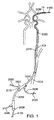
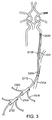
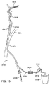
図1は、経頚部アプローチを介して総頚動脈CCAにアクセスするための、及び脳血管系にデバイスを送達するための、デバイスのシステムを示す。システムは、内腔及びポート2015を有する動脈アクセスデバイス2010(時々、動脈アクセスシースと称する)、例えばシースを含む。動脈アクセスデバイス2010は、経頚部の切開又は穿刺を介して総頚動脈に挿入でき、脳血管系へのアクセスを提供する位置、例えば総頚動脈又は内頚動脈内に展開できる寸法及び形状にされている。ポート2015は、動脈アクセスデバイスの内腔へのアクセスを提供し、動脈アクセスデバイス2010を介して脳血管系への追加のデバイスを導入するように構成されている。
FIG. 1 shows a system of devices for accessing the common carotid artery CCA via a transcervical approach and for delivering the device to the cerebral vasculature. The system includes an
ある実施形態では、動脈アクセスデバイス2010による直接的な総頚動脈への経頚部アクセスは、皮膚の切開又は穿刺を介して経皮的に達成される。代替の実施形態では、動脈アクセスデバイス2010は、頚動脈に達する直接的な外科的切開を介して、総頚動脈CCAにアクセスする。別の実施態様では、動脈アクセスデバイスは、例えば後大脳動脈又は脳底動脈などの後方の脳血管系中の閉塞にアクセスするために、椎骨動脈の切開又は椎骨動脈の経皮的穿刺を経由して、脳底動脈BA又は後大脳動脈PCAへのアクセスを提供する。動脈アクセスデバイスは、順行性の血流を遮断するために閉塞バルーンを含んでいてもよい。総頚動脈へのエントリーでは、動脈アクセスデバイスは総頚動脈内の開口に直接に挿入され、その開口は、患者の鎖骨より上側で、患者の総頚動脈が内頚動脈と外頚動脈に分岐する分岐位置より下側に位置している。例えば、開口は、患者の総頚動脈が内頚動脈と外頚動脈に分岐する分岐位置よりもおよそ5cm〜7cmの距離だけ下側に位置してもよい。
In certain embodiments, transcervical access to the common carotid artery directly by the
また、システムは、動脈アクセスデバイス2010の最遠位端(distal-most end)より遠位側の位置への遠位アクセス及びその位置での局所的な吸引を提供するために、1つ以上の遠位カテーテル2030を含んでもよい。単一の遠位カテーテルは、1つ又は複数の閉塞にアクセスして治療するのに適していてもよい。より遠位へのアクセスが望まれるものの第1の遠位カテーテルでは不可能な場合には、より小径の第2の遠位カテーテルを、第1のカテーテルを通して挿入しても、又は第1のカテーテルと交換してもよい。ある実施形態では、遠位カテーテル2030は、ポート2015を介して動脈アクセスデバイス2010の内腔に挿入できるように構成される。遠位カテーテル2030は、閉塞サイトの近傍への設置を容易にするために、ガイドレールとして及びサポート手段として機能する、予め設置されたガイドワイヤ、マイクロカテーテル又は他にデバイスを利用してもよい。遠位カテーテルは、さらに、血管系を通りガイドワイヤ上へ設置するのを容易にするために、拡張素子(dilator element)を利用してもよい。遠位カテーテルが目標のサイトに又はその近傍に位置決めされたら、拡張器は除去されてもよい。その後、遠位カテーテル2030は、閉塞に吸引を適用するために使用されてもよい。また、カテーテル2030又は拡張器は、追加のカテーテル及び/又は介入デバイスを閉塞サイトに送達するために使用されてもよい。
The system may also include one or more to provide distal access to a location distal to the distal-most end of the
方法及びデバイスは、さらに、閉塞の除去を容易にするために、及び/又は遠位の塞栓を最小化するために、受動的な逆流(passive retrograde flow)だけでなく、受動的な吸引のためのデバイスも含んでいる。システムは、脳血管系の具体的な血行力学的要求(hemodynamic requirements)に対処するために、ユーザーにある程度の血流制御を提供する。システムは、血流コントローラ(flow controller)を含むことができ、それにより、ユーザーは、1つ以上のデバイスからの吸引のタイミング及びモードを制御することが可能になる。 The method and device may further provide for passive aspiration as well as passive retrograde flow to facilitate removal of the occlusion and / or to minimize distal emboli. It also includes other devices. The system provides some degree of blood flow control to the user to address the specific hemodynamic requirements of the cerebral vasculature. The system can include a flow controller, which allows the user to control the timing and mode of suction from one or more devices.
さらに図1を参照すると、例えばステントリーバー又はコイルリトリーバーなどの、経頚部アクセス用に構成された血栓回収デバイス4100が、動脈アクセスデバイスを通って血栓性閉塞サイトに展開されてもよい。血栓回収デバイス4100は、動脈アクセスデバイス2010を通して挿入され、マイクロカテーテルを介して脳血管内の閉塞を横切って展開される。必要に応じて、遠位カテーテル2030は、閉塞された血管サイトまで血栓回収デバイスをナビゲーションするのを容易にするために、及び/又は血栓回収デバイスによって凝血塊を回収中に閉塞サイトに吸引を提供するために、使用されてもよい。血栓回収デバイスとマイクロカテーテルとが一列になって、(使用する場合は)遠位カテーテル2030内に、そして動脈アクセスデバイス2010内に引き戻されることにより、凝血塊が回収される。
Still referring to FIG. 1, a
開示された方法及びデバイスは、さらに、脳の損傷を最小限にするために、手技中に脳のペナンブラを保護するデバイスも含んでいる。遠位灌流デバイス(distal perfusion device)は、閉塞サイトの向こう側の脳に灌流を供給するために手技中に使用されてもよく、それにより、血液不足による脳の損傷を低減することができる。これらの灌流デバイスは、さらに、血管中の閉塞に加わる順方向の血圧(forward blood pressure)を低減するための手段であり、そして吸引、機械的手段の一方又は両方により、閉塞を除去するのを支援する手段を提供する。 The disclosed methods and devices further include a device that protects the brain penumbra during the procedure to minimize brain damage. A distal perfusion device may be used during the procedure to deliver perfusion to the brain beyond the occlusion site, thereby reducing brain damage due to blood shortage. These perfusion devices are also a means for reducing the forward blood pressure applied to the occlusion in the blood vessel, and removing the occlusion by aspiration, mechanical means, or both. Provide a means to assist.
さらに、開示した方法及びデバイスは、経頚部の血腫という潜在的に深刻な結果を回避するために、脳動脈へのアクセスサイトを確実に閉鎖する手段を提供する。本願の開示は、追加の方法及びデバイスを提供する。 In addition, the disclosed methods and devices provide a means to securely close the access site to the cerebral artery to avoid the potentially serious consequences of transcervical hematoma. The present disclosure provides additional methods and devices.
<典型的な実施形態に係る動脈アクセスデバイス>
図1に示す動脈アクセスデバイス2010は、別個のイントロデューサシースを使用せずに総頚動脈CCAに直接挿入するように構成されている。この配置では、デバイスが、ガイドワイヤ上を動脈中へと滑らに導入されるように、デバイスの侵入部(entry)又は遠位チップ(遠位側の先端: distal tip)は、先細りにされ、そして先細りにされた拡張器を含んでいる。デバイス2010は、膨張した時に動脈を閉塞するように構成された閉塞バルーン(occlusion balloon)2020を含み得る。代替の実施形態では、動脈アクセスデバイス2010は閉塞バルーンを含んでいない。動脈アクセスデバイスは、さらに、近位アダプターを含んでいる。この近位アダプターは、止血弁を持った近位ポート2015を含んでおり、手技中の失血を防止又は最小にしつつ、デバイスの導入を可能にしている。ある実施形態では、このバルブは、固定シールタイプの受動バルブである。代替の実施形態では、このバルブは、例えばツイ−ボースト弁(Tuohy-Borst valve)又は回転式止血弁(RHV)などの開度調整可能弁(adjustable-opening valve)である。止血弁は近位アダプターと一体にされていてもよく、又はルアー接続(Luer connection)を介してアダプターの近位端に別個に取り付けられてもよい。動脈アクセスデバイス2010は、さらに、受動的又は能動的な逆流手段に接続され得る血流ライン2025(又はシャント)への接続を含んでいてもよい。血流ライン2025は、動脈アクセスデバイスからの血液をシャントするために、動脈アクセスデバイス2010の内腔と通じている内腔を有する。ある実施形態では、血流ライン2025は、動脈アクセスデバイス2010の遠位端と近位端との間の位置で動脈アクセスデバイス2010に取り付けられてそこから伸びているサイドアーム又はYアーム2027である。図1に示されるように、血流ライン2025は、デバイスが動脈アクセスデバイスの近位ポート2015に入る位置よりも遠位側に配置されている。代替の実施形態では、血流ライン2025は、別個に取り付けられたツイ−ボースト弁のYアームに取り付けられている。
<Arterial Access Device According to Exemplary Embodiment>
The
動脈アクセスデバイス2010は、さらにバルーン膨張用の管腔を含んでいてもよい。この管腔は、近位アダプターの第2のYアームにバルーンを流体流通的に接続(fluidly connect)している。このYアームは、一方活栓(one-way stopcock)2029で終端するチューブ(tubing)2028に取り付けられている。血管閉塞を望むときに、バルーンを膨張させるために、例えばシリンジなどの膨張装置(inflation device)が活栓2029に取り付けられてもよい。
The
図2に示されたある実施形態では、動脈アクセスデバイスは、別個のイントロデューサシース2110の近位止血弁2012を通してCCA内に挿入されるガイドカテーテル2105である。動脈アクセスデバイスは、さらに近位アダプターを含んでいる。この近位アダプターは、止血弁を備えた近位ポート2015を含んでおり、手技中の失血を防止又は最小にしつつデバイスの導入を可能にしている。ガイドカテーテル2105は、バルーン膨張用の管腔を含んでいてもよい。この管腔は、近位アダプターのYアームに取り付けられており、それはチューブ2128に接続される。チューブ2128は、バルーン膨張装置に接続するための一方活栓2129で終端している。ガイドカテーテル2105は、血流ライン2125と通じている第2のYアーム2107を含んでいてもよい。別個のシース2110を通した導入により、患者の体外で洗い流し(flushing)して再挿入するために、又はイントロデューサシース2110を除去せずにガイドカテーテル2105を他のガイドカテーテルに交換するために、ガイドカテーテル2105を取り除くことが可能になり、それにより、経頚部の切開を介して動脈へのアクセスを維持することができる。さらに、この配置によって、手技中に、動脈の挿入サイトを阻害することなく、閉塞バルーン2020の再位置決めが可能になる。さらに、図2の実施形態では、動脈アクセスデバイス2105の除去と、その後、手技の最後には、イントロデューサシース2110を通して血管クローザーデバイスの挿入とを可能にする。
In one embodiment shown in FIG. 2, the arterial access device is a
この実施形態の変形では、図3に示されるように、イントロデューサシース2110は、閉塞バルーン2205と、膨張ライン及びチューブ2318とを含んでいる。さらに、イントロデューサシース2110は、受動的又は能動的な逆流のために、血流ライン2310への接続を含んでいてもよく、ここで受動的又は能動的な逆流は、米国特許出願第12/176,250号及び米国特許出願第12,834,869号に記載されているように形成することができ、それらを参照して本明細書に組み込む。この実施形態は、患者が脳動脈の閉塞に加えて頚動脈の狭窄を有している場合で、ユーザーが、脳動脈の閉塞の治療前又は治療後に、引用した特許出願に記載されているような静的条件又は逆流条件下で頚動脈の狭窄を治療したい場合に有用であろう。
In a variation of this embodiment, the
さらに別の実施形態では、図4に示されるように、動脈アクセスデバイスは、2つの閉塞バルーン2405、2410と、その2つのバルーンの間に配置される側部開口(side opening)2415とを備えたデバイス2105aである。遠位側の閉塞バルーン2410は、動脈アクセスデバイス2105aの遠位端に又はその近傍に配置されており、近位側の閉塞バルーン2405は、動脈アクセスデバイスの作業部(working portion)の遠位端と近位端との間に配置される。遠位側の閉塞バルーン2410は、外頚動脈ECAに設置できる寸法及び形状であり、近位側の閉塞バルーン2405は、総頚動脈CCAに設置できる寸法及び形状である。そのような2重バルーン配置(dual balloon configuration)は、CCAとECAの両方から内頚動脈ICAへの血流を止めており、それは、ICAにデバイスを挿入することなしにICA内に位置決めした閉塞バルーンと機能的に同様の効果を有する。これは、ICAに疾患があり、それゆえアクセスによって塞栓が取り除かれて塞栓合併症を生じる場合や、又はICAへのアクセスがひどくねじ曲がっていて、達成するのが困難な場合や、若しくはその両方の場合に有利であろう。動脈アクセスデバイス2105の作業部分(working section)の側部開口2415は、遠位側の塞栓のリスクを低減し又は排除するために、血流を止めている間又は逆流させている間に、デバイス2416を、動脈アクセスデバイス2105aを介して導入し、そして側部開口2415を介してICAに挿入するのを許容する。その後、このデバイス2416を脳動脈閉塞の位置まで前進させて、閉塞を治療してもよい。
In yet another embodiment, as shown in FIG. 4, the arterial access device includes two
さらに別の実施形態では、図5に示されるように、動脈アクセスデバイスは、複数部分パーツ(例えば2パーツ)のテレスコープ式システム(telescoping system)2105bである。第1のパーツは、CCAに経頚部的に挿入できるように構成されたイントロデューサシース2110bである。第2の部分は遠位側伸張部(distal extension)2110cであり、イントロデューサシース2110bの近位端を通して挿入されて、シースの届く範囲をICAまで拡張する。シース2110bの遠位端及び伸張部2110cの近位端は、伸張部が完全に挿入されたときに2つのデバイスを通じて連続的な管腔が存在するように、重なり結合(lap junction)2113を形成する。結合したテレスコープ式システム2105bの長さがいくらか可変性であるように、重なり結合は可変長にしてもよい。遠位側伸張部2110cは、シース2110bを通して遠位側伸張部2110cの設置及び回収を可能にするテザー(tether)2111を含んでいる。ある実施形態では、遠位側伸張部は閉塞バルーンを含んでいる。この実施形態では、テザーは、バルーン膨張用の管腔を含んでいる。このテザーは、その近位端で、バルーン膨張デバイスに接続することができる。この配置は、管腔面積(luminal area)を犠牲にせずに、図2に示される2パートシステムの利点を提供する。
In yet another embodiment, as shown in FIG. 5, the arterial access device is a multi-part (eg, two-part)
ある実施形態では、動脈に入る動脈アクセスデバイスの作業部は、例えば、第1の層及び第2の層を含む2層以上の層から構成されている。内側ライナー(inner liner)は、内腔を通してデバイスが前進するための平滑面を供給するために、例えばPTFE(ポリテトラフルオロエチレン)又はFEP(フッ化エチレンプロピレン)などの低摩擦ポリマーから構成される。ライナーに機械的完全性(mechanical integrity)を供給する外側ジャケット材料(outer jacket material)は、例えばペバックス(Pebax)、ポリエチレン、ナイロン等の材料から構成されてもよい。第3の層は、ライナーとジャケットとの間の強化材から成ってもよい。補強層の目的は、デバイスが血管系の屈曲を通ってナビゲートしたときに、内腔の平坦化又はよじれを防止することであり、そして、吸引又は逆流のみならずデバイスのアクセスのために、スムーズな手段(unimpeded means)を提供することである。補強材は、ステンレス鋼、ニチノールなどの金属、又はPEEKなどの硬質ポリマーから形成されてもよい。構造体は、コイル若しくは組み紐(braid)、又は柔軟になるようにレーザー切断又は機械切断されたチューブであってもよい。さらに、デバイスは、蛍光透視法を用いたデバイスの配置を容易にするために、遠位チップに放射線不透過マーカーを有していてもよい。ある実施形態では、デバイスの作業部は、血管系を通るデバイスの前進しやすさを向上するために、親水性コーティングされていてもよい。 In some embodiments, the working portion of the arterial access device that enters the artery is composed of two or more layers including, for example, a first layer and a second layer. The inner liner is composed of a low friction polymer such as PTFE (polytetrafluoroethylene) or FEP (fluorinated ethylene propylene) to provide a smooth surface for the device to advance through the lumen. . The outer jacket material that provides mechanical integrity to the liner may be composed of materials such as Pebax, polyethylene, nylon, and the like. The third layer may consist of a reinforcement between the liner and the jacket. The purpose of the reinforcement layer is to prevent lumen flattening or kinking when the device navigates through the vasculature bend, and for access of the device as well as suction or backflow To provide unimpeded means. The reinforcement may be formed from a metal such as stainless steel, nitinol, or a hard polymer such as PEEK. The structure may be a coil or braid, or a tube that has been laser or machine cut to be flexible. In addition, the device may have a radiopaque marker on the distal tip to facilitate placement of the device using fluoroscopy. In certain embodiments, the working portion of the device may be hydrophilic coated to improve the ease of advancement of the device through the vasculature.
ある実施形態では、動脈アクセスデバイスの作業長(working length)は、CCAから挿入されたときに、近位内頚動脈を閉塞できるように構成された長さであり、例えば10〜15cmである。代替の実施形態では、動脈アクセスデバイスの作業長は、血管クローザーデバイスによる閉鎖に適した長さであり、例えば11cm以下である。別の実施態様では、デバイスは、CCAから挿入されたときに、遠位頚部内頚動脈(ICA)を閉塞するように構成された長さにされており、例えば15〜25cmである。さらに別の実施形態では、動脈アクセスデバイスは、CCAから挿入されたときに、ICAの錐体部(petrous)、海綿静脈洞部(cavernous)又は末端部(terminal portion)を閉塞するように構成された長さにされており、例えば20〜35cmである。この実施形態では、動脈アクセスデバイスの最遠位部分(その長さは約3〜約6cmであってもよい)は、ICAの錐体部内の弯曲に適応するように、さらに柔軟になるように構成されてもよい。このようなさらなる柔軟性は、この部分において、より低いデュロメーターの(デュロメーター測定値の小さい)外側ジャケット材料を用いることによって達成しうる。代わりに、ジャケット材料の壁部厚さを減じて、及び/又は補強層の密度を変更して、柔軟性を高めてもよい。例えば、コイル又は組み紐の間隔(pitch)を広げることができ、又はチューブの切断パターンを、より柔軟になるように変更してもよい。さらに、動脈アクセスデバイスの最遠位部分は、先細りにされて又は段を設けて、小径にされてもよい。 In certain embodiments, the working length of the arterial access device is a length configured to occlude the proximal internal carotid artery when inserted from the CCA, eg, 10-15 cm. In an alternative embodiment, the working length of the arterial access device is a length suitable for closure by a vascular closer device, for example 11 cm or less. In another embodiment, the device is of a length configured to occlude the distal internal carotid artery (ICA) when inserted from the CCA, for example 15-25 cm. In yet another embodiment, the arterial access device is configured to occlude the ICA petrous, cavernous or terminal portion when inserted from the CCA. For example, it is 20 to 35 cm. In this embodiment, the most distal portion of the arterial access device (which may be about 3 to about 6 cm in length) is made more flexible to accommodate the curvature within the ICA cone. It may be configured. Such additional flexibility can be achieved in this part by using a lower durometer (small durometer measurement) outer jacket material. Alternatively, the wall thickness of the jacket material may be reduced and / or the density of the reinforcing layer may be changed to increase flexibility. For example, the pitch of the coil or braid can be increased or the cutting pattern of the tube can be changed to be more flexible. Further, the distal most portion of the arterial access device may be tapered or stepped to a small diameter.
上述した動脈アクセスデバイスは、大腿動脈のアクセス位置から設置されるアクセスデバイスに比べて大幅に短い作業長を有している。大腿動脈からCCAまでの距離は約60〜80cmであるので、CCAアクセスサイトを利用するデバイスは、おおむねこの量だけ短くなるだろう。大腿動脈アクセス用にデザインされた比較可能なデバイスは、頚部ICAに展開するデバイスでは長さが80〜95cm(例えば、Concentric社のバルーンガイド)であり、錐体ICAにアクセスするために設計されたものでは、長さが95〜105cm(例えば、Penumbra社のニューロン6Fガイド)である。本明細書に開示されたアクセスデバイスの長さが短いので、デバイスの管腔を通る血流抵抗が低下し、吸引が生じ得る流量(rate)が増加する。この典型的な実施形態では、動脈アクセスデバイスの長さは約10cm〜約40cmである。ある実施形態では、動脈アクセスデバイスの長さは約10.5cmであり、ガイドカテーテルの長さは約32cmである。 The arterial access device described above has a significantly shorter working length than an access device installed from the access position of the femoral artery. Because the distance from the femoral artery to the CCA is about 60-80 cm, devices that use the CCA access site will be approximately this amount shorter. Comparable devices designed for femoral artery access are 80-95 cm in length for devices deployed in the cervical ICA (eg, Concentric balloon guides) and designed to access the cone ICA In one, the length is 95-105 cm (eg Penumbra neuron 6F guide). Because the length of the access device disclosed herein is short, the resistance to blood flow through the lumen of the device is reduced and the rate at which suction can occur is increased. In this exemplary embodiment, the length of the arterial access device is about 10 cm to about 40 cm. In one embodiment, the length of the arterial access device is about 10.5 cm and the length of the guide catheter is about 32 cm.
さらに、ユーザーの手が放射線によって被ばくするのを最小限にしつつ、ユーザーが、デバイスを近位側伸張部(proximal extension)の近位ポート中に挿入し、そこから動脈アクセスデバイスの管腔内に挿入できるように、動脈アクセスデバイスは、着脱可能な近位側伸張部を含んでいてもよい。近位側伸張部のデザインの一例は、2009年8月12日に出願された同時係属中の米国特許出願第12/540,341号に記載されており、引用して本明細書に組み込む。米国特許出願第12/633,730号、米国特許出願第12/645,179号及び米国特許出願第12/966,948号も、引用して本明細書に組み込む。 Furthermore, while minimizing exposure of the user's hand to radiation, the user inserts the device into the proximal port of the proximal extension and from there into the lumen of the arterial access device. The arterial access device may include a removable proximal extension for insertion. An example of a proximal extension design is described in co-pending US patent application Ser. No. 12 / 540,341, filed Aug. 12, 2009, incorporated herein by reference. U.S. Patent Application No. 12 / 633,730, U.S. Patent Application No. 12 / 645,179 and U.S. Patent Application No. 12 / 966,948 are also incorporated herein by reference.
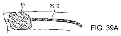
図1を再度参照すると、遠位カテーテル2030は、動脈アクセスデバイスを通って、ICA及び脳血管の遠位側で、血栓性閉塞10の位置まで、挿入されるように構成される。遠位カテーテル2030の長さは、遠位カテーテルの遠位端が約15〜25cmだけ動脈アクセスデバイスの遠位開口から突出するように、動脈アクセスデバイスの長さより長い。さらに、遠位カテーテルは、遠位血管系の解剖学的構造に起因して、動脈アクセスデバイスよりもさらに柔軟である。止血弁を備えた近位ポート2035は、遠位カテーテル2030の近位端に位置していてもよく、手技中の失血を防止又は最小にしつつ、マイクロカテーテル、ガイドワイヤ又は血栓回収デバイスなどのデバイスの導入を可能にしている。ある実施形態では、このバルブは、例えばツイ−ボースト弁又は回転式止血弁(RHV)などの開度調整可能弁である。止血弁はカテーテル近位アダプターと一体にされていてもよく、又はルアー接続を介してカテーテルの近位端に別個に取り付けられてもよい。
Referring again to FIG. 1, the
動脈アクセスデバイスと同様に、遠位カテーテル2030も、上述したように2層以上の層構成で形成されてもよい。遠位カテーテルは、上述された動脈アクセスデバイスの作業部の記載に従って形成されてもよい。さらに、遠位カテーテルは、蛍光透視法を用いたデバイスの配置を容易にするために、遠位チップに放射線不透過マーカーを有していてもよい。ある実施形態では、デバイスの作業部は、血管系を通るデバイスの前進しやすさを向上するために、親水性コーティングされていてもよい。ある実施形態では、最遠位部分は、動脈アクセスデバイス用に上述したような手段によって、近位部よりもさらに柔軟になるように構成されている。
Similar to the arterial access device, the
遠位カテーテル2030は、動脈アクセスデバイス2010を通して設置されたときに、末端部ICA及び脳血管に達するように構成された作業長を有する。ある実施形態では、作業長は40〜80cmである。この長さの遠位カテーテルでは、経大腿部アクセス用にデザインされたカテーテルよりも、ずっと高い流量の吸引が可能になるだろう。例えば、脳循環への経大腿部アクセス用に構成された遠位カテーテルは、長さが115cm、内径が0.057"(インチ)であり(カリフォルニア州マウンテンビューのConcentric Medical社製のDAC 057カテーテル)、22inHg(水銀柱インチ)の真空に設定された吸引ポンプに接続されたとき、3.2センチポアズ(cp、血液に等しい)の流体では流量(flow rate)113ml/分である。(本明細書に記述されているような)CCA内から脳循環への経頚部アクセス用に構成された遠位カテーテル2030は、長さが50cmで、同等の直径を備えていてもよい。血流抵抗は、チューブを通る流体についてのポアズイユの式に基づいて、チューブの長さに比例するので、カテーテル2030は、経大腿部カテーテルの2倍以上の流量を有しており、具体的には、22inHgに設定された吸引ポンプに接続されたとき、3.2cpの流体では流量260ml/分であり、経大腿部システムの吸引流量(aspiration rate)の約2.3倍である。また、手動のシリンジ吸引又は他の吸引源を用いて、吸引速度の同様の増加が見られるだろう。さらに、経頚部アクセスサイトは、経大腿部サイトよりも、多くの殆ど曲がっていない部分(many less turns)に遙かに近接しているので、カテーテルの壁部にそれほど高いトルク強度は必要なく、よって、経頚部的に設置されたカテーテル2030は、薄壁構成(thinner wall construction)で構築され、目標の解剖学的構造内に設置されるものと同等又はそれ以上の性能を備え得る。薄い壁部は大きな内腔をもたらし、流量についてさらなる優位性をもたらすだろう。血流抵抗は、直径の4乗に比例するので、管腔面積のわずかな改良でさえ、流量の増加の点で大きな優位性をもたらす。実施形態では、遠位カテーテルは(さらに遠位側の脳動脈ではなく)末端部ICAのみに達する寸法にされていてもよい。この実施形態では、遠位カテーテルは、内径0.070"〜0.095"、長さ25〜50cmであってもよい。別の実施態様では、遠位カテーテルは、より遠位側の脳動脈に達するためのサイズにされていてもよく、内径0.035"〜0.060"、長さ40〜80cmであってもよい。
The
動脈アクセスデバイスと同様に、遠位カテーテルには可変剛性シャフト(剛性の変化するシャフト:variable stiffness shaft)であってもよい。この実施形態では、遠位カテーテルの最遠位部分(その長さは約3〜約6cmであってもよい)は、脳血管内の弯曲に適合するように、より柔軟に構成されてもよい。このようなさらなる柔軟性は、この部分において、より低いデュロメーターの(デュロメーター測定値の小さい)外側ジャケット材料を用いることによって達成しうる。シャフトは、当該シャフトのより近位側の部分に向かって次第に硬質になる部分を有し、最近位部が最も硬質のシャフト部を有していてもよい。 Similar to the arterial access device, the distal catheter may be a variable stiffness shaft (variable stiffness shaft). In this embodiment, the distal most portion of the distal catheter (which may be about 3 to about 6 cm in length) may be configured more flexibly to fit the curvature in the cerebral blood vessel. . Such additional flexibility can be achieved in this part by using a lower durometer (small durometer measurement) outer jacket material. The shaft may have a portion that becomes gradually harder toward a more proximal portion of the shaft, and the most proximal portion may have the hardest shaft portion.
ある実施形態では、閉塞バルーン2040は、遠位カテーテル2030に配置されてもよく、例えば順方向の動脈流又は血圧を制限するために動脈を閉塞するのに使用することができ、それは、閉塞の除去のみならず吸引も可能にする条件を向上するだろう。
In certain embodiments, the occlusion balloon 2040 may be placed on the
まだ図1を参照すると、遠位カテーテル2030は、血流ライン2045(又はシャント)用の
Yアームを備えた近位アダプターを含んでいてもよい。血流ライン2045は、遠位カテーテル2030の内腔と通じている内腔を有する。近位アダプターは、さらに、ガイドワイヤ、マイクロカテーテル又は他のカテーテルの挿入用の近位止血弁2035を含んでいる。ある実施形態では、近位アダプターは、遠位カテーテル2030に、取り外せないように取り付けられている。別の実施態様では、近位アダプターは、Yアームを備えた別個のツイ−ボースト弁を取着可能なメスのルアーコネクタ(Luer connector)である。
Still referring to FIG. 1,
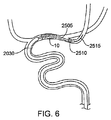
別の実施態様では、遠位カテーテルシステムは、血管系を通って脳閉塞よりも遠位側の位置まで容易にナビゲート可能に構成されたアンカーデバイス(anchor device)を含んでいる。アンカーを展開したときには、閉塞の近位面への遠位カテーテルの前進を容易にするために、それはレール応力(rail force)及び反力(counter force)として使用されてもよい。図6に示す例は、遠位のバルーン2510を備えたマイクロカテーテル2505である。マイクロカテーテル2505を、閉塞10を通ってガイドワイヤ2515上に設置し、そして遠位バルーン2510を膨張させる。代わりに、マイクロカテーテルは組み込みの非外傷性のガイドワイヤチップ(又はガイドワイヤの先端部)を有して、独立したデバイス(stand-alone device)として前進する。その後、従来技術で行われるように、遠位カテーテル2030は、閉塞10に向かって前進させるためのレールとして、マイクロカテーテル2505のシャフトを利用することができる。しかしながら、バルーン2510が膨張しているので、マイクロカテーテル2505の遠位端は凝血塊及び/又は血管壁に係留され、遠位カテーテル2030の前進に対する反力を提供する。力のいくらかが閉塞自体に伝わるかもしれず、凝血塊を除去するのを助けるかもしれない。ガイドワイヤ2515はこの手技(maneuver)中に所定位置に留まっているので、これにより、閉塞10の除去を再び試みるためにアンカー(すなわちバルーン2510)と遠位カテーテル2030を再び前進させる必要があるときに、アクセスは、ガイドワイヤ2515によって、閉塞を横切って維持される。
In another embodiment, the distal catheter system includes an anchor device configured to be easily navigable through the vasculature to a location distal to the cerebral occlusion. When the anchor is deployed, it may be used as a rail force and counter force to facilitate advancement of the distal catheter to the proximal surface of the occlusion. The example shown in FIG. 6 is a
非外傷性の遠位アンカーは、バルーン以外のデバイスであってもよい。例えば、他の非外傷性の遠位アンカーは、機械的に拡張可能な先端(例えば、組み紐、コイル又はモリーボルト(molly-bolt)構造体など)を備えたマイクロカテーテルを含むことができる。拡張可能な先端は、十分に柔軟となるように、そして、血管壁に対する局所的な圧力(focal pressure)が低減され血管壁の損傷が最小にすべくマイクロカテーテルの長さに沿って十分な力を提供するように、構成することができる。 The atraumatic distal anchor may be a device other than a balloon. For example, other atraumatic distal anchors can include microcatheters with mechanically expandable tips (eg, braids, coils, molly-bolt structures, etc.). The expandable tip is sufficiently flexible and has sufficient force along the length of the microcatheter to reduce local pressure on the vessel wall and minimize vessel wall damage Can be configured to provide
この実施形態の別の変形例は、図7に示されるように、バルーン、又は拡張可能なケージ若しくはステントなどの拡張可能な先端2620を備えたガイドワイヤ2615である。ガイドワイヤ2615は、マイクロカテーテルを利用して血管系内に設置され、そしてマイクロカテーテルを引き込ませるときに展開する。ガイドワイヤ2615デバイスの拡張可能な部分は、別個の編状フィラメント(braided filament)から形成されてもよく、又は、単一のハイポチューブ(hypotube)から切り取られて、反力作動部材(counterforce actuating member)によって拡張されてもよい例えば、拡張可能な先端の近位端は、中空のハイポチューブの遠位端に取り付けられてもよく、遠位端は、ハイポチューブの長さ方向に伸びたワイヤに取り付けられてもよい。ワイヤを引き戻すと、拡張可能な先端は、長さが短くなり、直径が拡張される。ワイヤを前方向に押すと、拡張可能な先端は折り畳まれるだろう。
Another variation of this embodiment is a
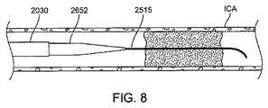
大きいサイズのカテーテルを前進させることの困難さの原因は、カテーテルと内部構成との不適切な組合せ(mismatch)にある。大きいサイズのカテーテルを前進させるための1つの技術は、3軸技術(tri-axial technique)と呼ばれており、小さいカテーテル(マイクロカテーテル又は小径の遠位カテーテルのいずれか一方)を、大きいカテーテルとガイドワイヤとの間に設置する。しかしながら、現在のシステムでは、小さいカテーテルは、大きいカテーテル、ガイドワイヤ又はそれら両方との間における直径の不整合(diameter mismatch)があり、それは、システムが血管系中を前進するときのシステムの最先端(leading edge)に段差を生じる。この段差は、非常に曲がった血管をナビゲートする際、特に側枝(例えば眼動脈)が存在する位置では、困難さの原因となるだろう。ある実施形態では、図8に示されるように、遠位カテーテル2030には、通常使用される小さいカテーテルと交換される、先細りにされた同軸の内側部材2652が供給される。内側部材2652は、遠位カテーテルの内腔を通して挿入できる寸法及び形状である。内側部材2652は、遠位カテーテル203の内径と、内側部材2652の内腔を通して伸びるガイドワイヤ2515又はマイクロカテーテルの外径との間に滑らかな移行部を形成する外径を備えた先細り領域(テーパー領域)を有している。ある実施形態では、先細りにされた拡張器又は内側部材2652は、遠位カテーテル内に配置したときに、大きい遠位カテーテル2030の最遠位の先端と、例えば直径が0.014"及び0.018"の範囲にあり得るガイドワイヤ2515の外径と、の間の滑らかな移行部を形成する。例えば、内腔の直径は、例えば0.020"〜0.024"であってもよい。別の実施態様では、内径は、例えば外径が0.040"〜0.030"の範囲内にあるマイクロカテーテル又は0.035"のガイドワイヤを内腔に受容できるように構成されており、例えば、内腔の直径は0.042"〜0.044"であってもよい。
The cause of the difficulty of advancing large size catheters is due to the mismatch between the catheter and the internal configuration. One technique for advancing large size catheters is called the tri-axial technique, where a small catheter (either a microcatheter or a small diameter distal catheter) is replaced with a large catheter. Install between guide wires. However, in current systems, small catheters have a diameter mismatch between the large catheter, guidewire, or both, which is the state of the art of the system as it advances through the vasculature. A step is formed at the (leading edge). This step can be a source of difficulty when navigating highly bent blood vessels, especially where side branches (eg, ophthalmic arteries) are present. In one embodiment, as shown in FIG. 8, the
この実施形態の変形例では、図9に示されるように、テーパー領域に加えて、内側部材2652は、内側部材2652のテーパー部を超えて遠位側に伸びている一定の直径又は単一の直径の最遠位領域2653から形成された伸張部を含んでいる。この実施形態では、内側部材2652の遠位領域2653は、マイクロカテーテルが脳卒中の介入手技中に役立つであろういくつかの又は全ての機能、例えば、遠位側の血管造影を行うために閉塞を横切る、凝血塊中に動脈内血栓溶解剤(intraarterial thrombolytic agents)を注入する、又はコイルリトリーバー又はステントリトリーバーなどの機械的な血栓回収デバイスを送達する、などを実現しうる。このように、マイクロカテーテルは、発生するこれらの工程のために拡張器と交換する必要がなくなるだろう。
In a variation of this embodiment, as shown in FIG. 9, in addition to the tapered region, the
拡張器(内側部材2652)の材料が十分に柔軟であり、テーパー部が十分に長いので、ガイドワイヤの柔軟性と遠位カテーテルとの間に滑らかな移行部を形成することができる。この配置は、遠位カテーテルを、曲がった解剖学的構造を通って目標の脳血管系まで前進させるのを容易にするだろう。ある実施形態では、拡張器は、可変剛性を有するように構成されており、例えば、最遠位部分は軟質な材料から形成され、近位部分に向かって次第に硬質な材料でから形成される。 Because the material of the dilator (inner member 2652) is sufficiently flexible and the taper is sufficiently long, a smooth transition can be formed between the guidewire flexibility and the distal catheter. This arrangement will facilitate the advancement of the distal catheter through the bent anatomy to the target cerebral vasculature. In certain embodiments, the dilator is configured to have variable stiffness, for example, the distal most portion is formed from a soft material and is formed from a progressively harder material toward the proximal portion.
ある実施形態では、先細りにされた拡張器の遠位端には、白金/イリジウムバンド、タングステン、白金又はタンタルを含ませたポリマーなどの放射線不透過マーカー又はその他の放射線不透過マーカーを備えている。ある実施形態では、先細りにされた拡張器は可変剛性に構成される。例えば、拡張器の遠位部(distal segment)が軟質な材料から構成され、近位端に向かって連続的に硬質な材料にされてもよい。図1に示されるように、遠位カテーテル2030は、それ自体が、動脈アクセスデバイスとは別個に且つ着脱可能なカテーテルになりえる。別の実施態様では、図10に示されるように、遠位カテーテルと動脈アクセスデバイスとは、デバイスの長さを通して伸びる連続的な管腔を有する単一のデバイス2710となるように、結合される。近位部2720は、動脈アクセスシースと、遠位カテーテルとして機能する遠位部2730とを含んでいる。閉塞バルーン2715は、遠位部と近位部との間に位置している。遠位部2730は、脳血管系のナビゲートに最適となるように構成される。特に、遠位部2730は、近位部2720よりも柔軟で且つ小径にテーパーされている。
In certain embodiments, the distal end of the tapered dilator is equipped with a radiopaque marker or other radiopaque marker, such as a platinum / iridium band, a polymer containing tungsten, platinum or tantalum. . In certain embodiments, the tapered dilator is configured for variable stiffness. For example, the distal segment of the dilator may be composed of a soft material and continuously hardened toward the proximal end. As shown in FIG. 1, the
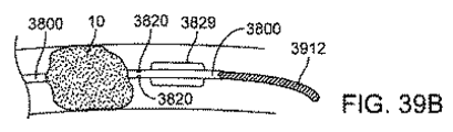
別の実施態様では、図11及び12に示されるように、遠位カテーテルは、目標となる解剖学的構造を再横断することなしに遠位カテーテルの再前進(re-advancement)又は交換を容易にするために、ガイドワイヤアクセスを維持する第2の管腔を有している。図11に示す実施形態では、遠位カテーテルは、遠位チップにおいて終端する2つの管腔(主腔(main lumen)及び第2のガイドワイヤ管腔(second guidewire lumen))を有している。終端部では、遠位向きの表面(distal-facing surface)を、血管系を通してカテーテルのトラッキング(追跡:tracking)が容易になるように(カテーテルの長手軸に対して)角度をつけて配置してもよい。別の実施態様では、図12に示されるように、第2のガイドワイヤ管腔は、主腔の終端部を超えて延在する伸張部(an extension)1247の内側にある。伸張部1247は、主腔によって形成された開口を超えて遠位側に突出した遠位カテーテルの最遠位領域である。伸張部1247は、主腔を取り巻く遠位カテーテルの外径と比較して、減少された外径を有するシャフトを形成する。第2の管腔は、メインの遠位カテーテル(main distal catheter)のシャフトよりも小さく、主腔の遠位端が閉塞の近位側の表面上に位置決めされたときに、その閉塞内に又はそれを横切って配置されてもよい。主腔の遠位端は、デバイスのトラッキングを容易にするために、同様に角度を付けて終端してもよい。
In another embodiment, as shown in FIGS. 11 and 12, the distal catheter facilitates re-advancement or replacement of the distal catheter without re-traversing the target anatomy. To have a second lumen that maintains guidewire access. In the embodiment shown in FIG. 11, the distal catheter has two lumens (a main lumen and a second guidewire lumen) that terminate at the distal tip. At the end, the distal-facing surface is placed at an angle (relative to the longitudinal axis of the catheter) to facilitate catheter tracking through the vasculature. Also good. In another embodiment, as shown in FIG. 12, the second guidewire lumen is inside an
さらに別の実施形態では、遠位カテーテルは、拡張可能な先端部分(expandable tip portion)を有している。吸引デバイスが遠位カテーテルの近位部に接続される場合に、拡張可能な先端は、閉塞の吸引を容易にする。拡張可能な先端部分は、組み紐又はステント構造体などの機械的構造体から構成されてもよく、それらは繰り返し開閉することができる。先端(チップ)を開くための機構は、拡張可能な部分を短縮する引張りワイヤであってもよく、又は、遠位部分を小さい直径に維持するが、引き込んだときにじは遠位チップが拡大できるようにする外側保持スリーブ(outer retention sleeve)であってもよい。吸引を適用したときに、先端が拡張してもしなくても真空がカテーテルのまさにその先端に適用され得るように、遠位部分は膜(membrane)で覆われていてもよい。拡張可能な先端は、カテーテルを目標となる解剖学的構造までトラッキングする間に、カテーテルを小さいプロファイルに維持することを可能にするが、血栓などの閉塞性物質を容易に捕獲するために、その後に遠位側の管腔面積を拡張する。遠位カテーテル内に捕獲されたら、血栓は、吸引デバイス内まで吸収されてもよく、その代わりに、カテーテルをもはや拡張しない場合には血栓を遠位カテーテルの内腔に詰まらせて、その時点で遠位カテーテル全体を引き込む(又は引き出す)ことにより除去することができる。 In yet another embodiment, the distal catheter has an expandable tip portion. The expandable tip facilitates suction of the occlusion when the suction device is connected to the proximal portion of the distal catheter. The expandable tip portion may be composed of a mechanical structure such as a braid or a stent structure, which can be repeatedly opened and closed. The mechanism for opening the tip (tip) may be a pull wire that shortens the expandable portion, or maintains the distal portion at a small diameter, but the distal tip expands when retracted It may be an outer retention sleeve that allows it to be done. The distal portion may be covered with a membrane so that when suction is applied, a vacuum can be applied to the very tip of the catheter, whether the tip is expanded or not. The expandable tip allows the catheter to be maintained in a small profile while tracking the catheter to the target anatomy, but then to easily capture occlusive substances such as thrombus To expand the distal lumen area. Once captured in the distal catheter, the thrombus may be absorbed into the aspiration device; instead, if the catheter is no longer expanded, the thrombus is clogged into the distal catheter lumen, at which point It can be removed by retracting (or withdrawing) the entire distal catheter.
別の実施態様では、図13に示されるように、遠位カテーテル2830は、動脈アクセスデバイス2820の遠位部に取り付けるテレスコープ式アタッチメント(telescopic attachment)である。動脈アクセスデバイス2820の遠位領域は、動脈アクセスデバイスの長手軸に沿って遠位方向にテレスコープ式に伸びる1つ以上の構造体を有している。構造体は、それらが動脈アクセスデバイスの遠位端を超えて延在しないように、テレスコープ式に折り畳まれていてもよい。構造体が動脈アクセスデバイスの遠位端を超えてテレスコープ式に拡張する場合、構造体は共同で連続的な内腔を形成する。ワイヤ2835などのテザー要素は、テレスコープ式の作動が、動脈アクセスデバイスの近位端から達成されうるように、遠位部2830に接続されて、動脈アクセスデバイスの近位端を拡張してもよい。バルーン2815などの拡張可能な部材は、デバイス2820に位置決めされてもよい。
In another embodiment,
図14は、代替の実施形態に示しており、バルーンカテーテル2502などの補助的な装置(secondary device)は、動脈アクセスデバイス2010を通って、前大脳動脈ACAなどの側副の脳動脈(collateral cerebral artery)内まで前進させられる。バルーンカテーテル2502は、側副の脳動脈中で拡張してその動脈を閉塞することができる拡張可能なバルーン2530を含んでいる。以下に詳述するように、側副の脳動脈の閉塞は、脳血管系と通る吸引及び逆流を強める。
FIG. 14 shows an alternative embodiment in which a secondary device, such as a
<吸引と血流制御の典型的な実施形態>
動脈アクセスデバイス2010及び遠位カテーテル2030のいずれか一方又は両方は、デバイス上の血流ライン2025、2045(図1)を介して、受動的又は能動的な吸引源に接続されてもよい。吸引のモードはデバイスごとに異なってもよい。
<Typical Embodiment of Suction and Blood Flow Control>
Either or both of the
図15では、動脈アクセスデバイス2010の血流ライン2025は、レセプタクル3100などの送達位置(delivery location)に接続される。吸引源3125は、血流ライン2025に結合されてもよい。レセプタクル3100と吸引源3125とは別個であってもよく、又は、シリンジなどの単一デバイスに組み込んでもよい。フィルター3418及び/又は逆止弁3419は、血流ライン2025に連結されてもよい。図16では、遠位カテーテル2030の血流ライン2045は、追加で又は代わりに、別個の吸引源3425とレセプタクル3105などの送達位置とに接続される。吸引源3425及び送達位置は、シリンジなどの単一デバイスに組み込んでもよい。フィルター3418及び/又は逆止弁3419は、血流ライン2045に連結されてもよい。
In FIG. 15,
図17はシステムを示しており、動脈アクセスデバイス2010及び遠位カテーテル2030の両方が、血流ライン2025、2045の各々を介して、同一の吸引源3430に接続されている。バルブ3325は、どちらのデバイスを吸引源3430に接続するかを制御する。バルブは、一方のデバイス、他方のデバイス、両方のデバイス、又は接続すべき別の(いずれでもない)デバイスに、いつでも吸引源を接続することができる。バルブは三方活栓又は四方活栓であってもよい。代わりに、バルブは、上述したような配置を選択する単純作動の血流コントローラであってもよい。
FIG. 17 shows the system, where both the
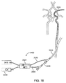
ある実施形態では、血流コントローラは、単一ユニット内の多数のデバイスを通して多数の吸引手段の制御を容易にしてもよい。この配置により、一人のオペレーターによるシステムの使用を容易になるだろう。血流コントローラは、例えば動脈アクセスデバイス、遠位カテーテル、それら両方又はそれ以外などのデバイスが吸引されるのを調節するために、ユーザーが作動させることのできる1つ以上の制御インターフェースを含んでいてもよい。図18は、そのような血流コントローラ3400を利用するシステムの実施形態を示す。血流コントローラ3400は、遠位カテーテル2030の血流ライン2045のみならず、動脈アクセスデバイス2010の血流ライン2025にも接続される。このように、血流ライン2025、2045は、動脈アクセスデバイス2010及びカテーテル2030から、それぞれ、血流コントローラ3400へと血流が流れるのを可能にする。コントローラ3400は、受動的な吸引源3410及び能動的な吸引源3420のいずれか又は両方に接続されてもよい。血流コントローラハウジング3429は、各デバイスが、どのように及びいつ、各吸引源に接続されるかを決定するための制御メカニズムを含んでいる。制御メカニズムは、さらに、各吸引源からの吸引レベルを制御してもよい。さらに、コントローラは、脳閉塞の崩壊とその吸引とを促進するために、拍動性の吸引モードを可能にする制御を含んでもよい。血流コントローラは、連続的な吸引モードと拍動性の吸引モードとの間で切り替えるためのインターフェースを有していてもよい。制御メカニズムは、片手で操作可能であるようにデザインされてもよい。例えば、制御メカニズムは、トグルスイッチ(toggle switches)、押しボタンスイッチ、スライダーボタンなどであってもよい。ある実施形態では、血流コントローラ3400は、ユーザーが脳循環への順行性の血流をすぐに回復できるようにするためのインターフェースであり、同時に動脈アクセスデバイスの閉塞バルーンを収縮し吸引を止める例えば単一のボタン又はスイッチなどを備えたものを有している。
In certain embodiments, the blood flow controller may facilitate control of multiple suction means through multiple devices within a single unit. This arrangement will facilitate the use of the system by one operator. The blood flow controller includes one or more control interfaces that can be actuated by a user to adjust the aspiration of a device, such as, for example, an arterial access device, a distal catheter, or both. Also good. FIG. 18 illustrates an embodiment of a system that utilizes such a
能動的な吸引源は、吸引ポンプ、通常のシリンジ又はロックシリンジ、携帯型吸引器、病院での吸引 (hospital suction)などであってもよい。ある実施形態では、手技の血栓回収工程より前に血流ラインへの接続が閉じられた状態で、ロックシリンジ(例えば、バックロックシリンジ: VacLok Syringe)は血流コントローラに取り付けられ、プランジャーはユーザーによってロック位置まで引き戻される。手技中に、吸引デバイス(動脈アクセスデバイス又は遠位カテーテルのいずれか)の先端が閉塞の表面近傍又は表面にあるときに、ユーザーは、吸引シリンジへの接続を開いてもよい。このことは、1人のユーザーによって、急速に最大レベルの吸引を可能にするが、そのいくつかは現在、既存の技術では不可能である。別の実施態様では、吸引源は、吸引デバイスを分離せずに吸引及び補充(refill)ができるように構成された携帯型の吸引器である。この実施形態の例では、携帯型の吸引器は、片手で操作できるアクチュエーターで上下移動されるプランジャーを備えたチャンバーを含んでいる。プランジャーが上下移動したときに、シリンジでは必要とされ得るチャンバーの取り外し及び空にすることを必要としないチャンバーへの又はチャンバーからの連続的な吸引源が存在するように、チャンバーは入出力バルブを含んでいる。チャンバー入力はカテーテルに接続され、チャンバー出力は血液収集バッグなどの収集レセプタクルに接続される。ある実施形態では、この吸引源は片手だけで使用できるように構成される。 The active suction source may be a suction pump, a normal or lock syringe, a portable suction device, a hospital suction, and the like. In one embodiment, a lock syringe (e.g., VacLok Syringe) is attached to the blood flow controller and the plunger is connected to the user with the connection to the blood flow line closed prior to the procedure's thrombus collection step. Is pulled back to the locked position. During the procedure, the user may open a connection to the suction syringe when the tip of the suction device (either the arterial access device or the distal catheter) is near or at the surface of the occlusion. This enables a maximum level of suction rapidly by one user, some of which are currently not possible with existing technologies. In another embodiment, the aspiration source is a portable aspirator configured to allow aspiration and refill without separating the aspiration device. In this embodiment example, the portable aspirator includes a chamber with a plunger that is moved up and down by an actuator that can be operated with one hand. The chamber is an input / output valve so that when the plunger moves up and down there is a continuous source of suction to or from the chamber that does not require removal and emptying of the chamber, which may be required for a syringe. Is included. The chamber input is connected to a catheter and the chamber output is connected to a collection receptacle such as a blood collection bag. In some embodiments, the suction source is configured to be used with only one hand.
吸引源の1つの不利益は、吸引された血液が外部リザーバ(又は外部容器)又はシリンジに受容されるということである。この血液は通常は手技の最後に廃棄されるので、患者からの失血を意味している。さらに、遠心ポンプ又は蠕動ポンプなどのポンプは、血球に損傷をもたらすことが知られている。外部リザーバから患者に血液を戻すことは可能であるが、血液は空気に露出しているか又は一時期は静置されており、血栓形成又は血球損傷のリスクがある。通常、吸引された血液は、血栓塞栓症(thromboembolism)のリスクを回避するために、患者に戻さない。 One disadvantage of the suction source is that the aspirated blood is received in an external reservoir (or external container) or syringe. This blood is usually discarded at the end of the procedure, meaning blood loss from the patient. In addition, pumps such as centrifugal pumps or peristaltic pumps are known to cause damage to blood cells. Although it is possible to return blood to the patient from an external reservoir, the blood is exposed to air or left at rest for some time and there is a risk of thrombus formation or blood cell damage. Normally, aspirated blood is not returned to the patient to avoid the risk of thromboembolism.
図19は、血球を傷つけないように構成され、手技中にリアルタイムで中心静脈システムに血液を戻すように構成された典型的な吸引ポンプデバイス3250の断面図を示しており、そのため、血液が静置されたままにされるリザーバは存在しない。ポンプ3250は、動脈アクセスデバイス2010及び遠位カテーテル2030のいずれか一方又は両方に接続されてもよい。ポンプデバイス3250は、血流ライン2025の一部を含むチャンバー3220を囲んでいるハウジング3215を含む。チャンバー3220内に含まれている血流ライン2025の拡張可能な部分(expandable portion)3210は、その自然な状態(図19に破線で示されている)では縮んだ直径であるが、拡張した直径(図19に実線で示されている)に変更できるように構成され得るように、弾性材料から作られる。Oリングなどの1つ以上のシール3125は、チャンバー3220と血流ライン2025の間の接合部分を密閉する。真空源3230はチャンバー3220に接続されており、チャンバー3220の内の圧力を変更するために操作できるように構成される。2つの一方向逆止弁3235が、拡張可能な部分3210の両側の血流ライン2025内に位置している。
FIG. 19 shows a cross-sectional view of a typical
ポンプデバイス3250の操作では、真空源3230は、チャンバー3220の内に、血流ライン管腔3210内の圧力に対して減圧を生成するために操作される。図32に実線で示されるように、チャンバー3220と血流ライン管腔3210との間の圧力差は、血流ライン2025の拡張可能な部分3210を拡張させて、チャンバー3220内で容積を増加させる。逆止弁3235によって制御されるため、この拡張によって、血液は、「流入」の矢印で示されるように血流ラインのシース側から拡張可能な部分3210へと引っ張られる。その後、真空源3230は、チャンバー3220の内の圧力を正常化するように止められてもよい。これにより、図19に破線で示されるように、拡張可能な部分3210を小さい自然な直径に戻らせる。逆止弁3235は、血流ライン2025の予め拡張された領域内の血液を、図19の「外側」の矢印で示されたように、位置3120の方向に放出する。真空源3230は、拡張可能な部分3210を、拡張状態と引込み状態との間で規則的に変動するように操作されて、そして一方向逆止弁3235と協働し、それにより、血流ライン管腔3210を通る血流を駆動させてもよい。
In operation of the
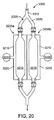
図20は、一対のポンプデバイス3205a、3205bを含むポンプシステム3305を示しており、その各々は図32に示されるタイプのものである。
すなわち、各デバイス3205は、血流ライン2025の一部を包含するチャンバーを包含しているハウジング3215を含む。ポンプデバイス3205a、3205bは、各ポンプデバイス3205が拡張可能な部分3210を備えた血流ライン2025を有するように、血流ライン2025と平行に接続される。一対のポンプデバイス3205a、3205bは、ポンプシステム3305を通して比較的連続流の状態を形成するために、拡張状態(expanded state)と引込み状態(retracted state)とを交互にされてもよい。ポンプ3205a、3205bが、ポンプシステム3305を通して総合的には中断のない血流を駆動するように、例えば、ポンプ3205bが引込み状態にされているときに、ポンプデバイス3205aが拡張状態にされてもよい。
FIG. 20 shows a
That is, each device 3205 includes a
さらなる利点のあるポンプシステム3250又は3305は、本明細書に記載されているように、中心静脈システムに血液を戻すように構成されている受動的な逆流システムと共に使用し得るということである。これら2つのシステムは、静脈リターンラインを共有してもよく、それらはバルブ又は他の流量制御デバイスにより接続される。
A further advantage is that the
吸引の受動源(passive source)は、例えば、(静脈リターン用に)中心静脈に挿入されたシース、又は望まれる陰圧の程度によって変化し得る垂直レベルに設置されたIV(静脈)バッグなどの、低圧のサイトであってもよい。図21は、動脈アクセスデバイスへの受動的な逆流を確立するために、静脈リターンを使用するシステム3500の典型的な実施形態を示す。システム3500は、動脈アクセスデバイス3510、静脈リターンデバイス3515、及び動脈アクセスデバイス3510から静脈リターンデバイス3515までの逆流に通路を提供する血流ライン3520を含んでいる。血流制御アセンブリ3525は、血流ライン3520に相互作用する。血流制御アセンブリ3525は、血流ライン3520を通る逆流を調節及び/又は監視(モニター)するのに適している。血流制御アセンブリ3525は、血流ラインを通して血流の状態及びレベルを決定するために、血流ライン3520を介して血流経路と相互作用する。
A passive source of aspiration can be, for example, a sheath inserted into a central vein (for venous return) or an IV (venous) bag placed at a vertical level that can vary depending on the degree of negative pressure desired. It may be a low-pressure site. FIG. 21 illustrates an exemplary embodiment of a
実施形態では、以下に詳細に説明するように、動脈アクセスデバイス3510は、少なくとも部分的に総頚動脈CCA及び静脈リターンデバイス3515に挿入され、そして少なくとも部分的に、大腿静脈か内頚静脈などの静脈リターンサイトに挿入される。静脈リターンデバイス3515は、鼠径部に経皮的穿刺によって大腿静脈FVに挿入することができる。動脈アクセスデバイス3510及び静脈リターンデバイス3515は、コネクターで、血流ライン3520の対向する端部に接続される。閉塞要素3529を備えた動脈アクセスデバイス3510の遠位端は、ICA内に位置決めされてもよい。代わりに、ICAアクセスが非常に曲がっているような状況においては、総頚動脈中のより近位側に閉塞要素を位置決めするのが好ましいだろう。内頚動脈を通る血流が(閉塞要素3529を使用して)遮断された場合、内頚動脈と静脈系との間の自然な圧力勾配により、血液は、脳血管系から内頚動脈を通り、そして血流ライン3520を通って静脈系へと逆行又は逆方向に流れる。
In embodiments, as described in detail below, the
別の実施態様では、動脈アクセスデバイス3510は、経頚部アプローチを介して総頚動脈CCAにアクセスし、静脈リターンデバイス3515は、大腿静脈以外、例えば内頚静脈などの静脈リターンサイトにアクセスする。別の実施態様では、システムは、頚動脈から、静脈リターンサイトではなく外部レセプタクル(例えばIVバッグ)に逆流を提供する。動脈アクセスデバイス3510は、血流ライン3520を介してレセプタクルに接続しており、それは血流制御アセンブリ3525と通じている。逆流は、レセプタクルに集められる。所望により、血液をろ過し、そして患者に戻すことができる。レセプタクルの圧力は、圧力0(大気圧)又はさらに低く設定することができ、脳血管系からレセプタクルへと逆方向に血液を流すことができる。
In another embodiment, the
<血栓回収デバイスの典型的な実施形態>
開示されたデバイスシステムのいずれかと共に使用するための血栓回収デバイスの典型的な実施形態は、例えば上述のデバイスであって経頚部的に設置するように構成されたものである。具体的には、血栓回収デバイスは、それが伸びて、脳閉塞にアクセスし横断するのに十分な長さの動脈アクセスデバイス2010又は遠位カテーテル2030から出ることができるような作業長を有している。より具体的には、作業長が80〜120cmの血栓回収デバイスである。
<Typical Embodiment of Thrombus Recovery Device>
An exemplary embodiment of a thrombectomy device for use with any of the disclosed device systems is, for example, the above-described device configured for transcervical placement. Specifically, the thrombectomy device has a working length such that it can elongate and exit the
実施形態では、経頚部アクセスのために構成されたマイクロカテーテルが、システム100の一部として含まれている。より具体的には、作業長が100〜140cmのマイクロカテーテルが、システム100に含まれている。マイクロカテーテルは、血栓回収デバイスの血管造影及び/又は送達に使用されてもよい。 In an embodiment, a microcatheter configured for transcervical access is included as part of system 100. More specifically, the system 100 includes a microcatheter having a working length of 100-140 cm. The microcatheter may be used for angiography and / or delivery of a thrombectomy device.
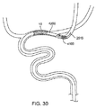
血栓回収デバイスのさらなる実施形態を以下に記載する。図22は、拡張可能な部材4112から近位側に伸びる細長い柔軟なカテーテル4115に取り付けられた、自己拡張可能な部材4112から形成された典型的な血栓回収デバイス4100の遠位領域の拡大側面図を示す。拡張可能な部材4112は、複数のセル構造(ダイヤモンド形状であってもよい)を形成するように配列された絡み合った又は波打った複数の長手の支柱から形成されている。ある実施形態では、支柱は、当該支柱に音響エネルギーを適用できるようにするエネルギー源に接続される。拡張可能な部材4112は、減少したサイズと拡大したサイズとの間で移行するように構成されており、拡張可能な部材4112は、第1の直径から、カテーテル4115の長手軸に比べて大きい第2の直径まで、半径方向外向きに拡張する拡張可能な部材4112は、例えば、多くの血管内ステントを製造するのと同様の方法で、支柱を作成するために幾何学形状にレーザー切断された単一チューブから形成されてもよい。ある実施形態では、拡張可能な部材4112は、ニチノールなどの形状記憶材料から形成されている。拡張可能な部材4112は、米国特許公報第20110009875号に記載されている拡張可能な部材によって構成されてもよく、その全体を参照して本明細書に組み込む。
Further embodiments of the thrombectomy device are described below. FIG. 22 is an enlarged side view of the distal region of an
使用において、拡張可能な部材4112は、上述のような動脈アクセスデバイスを介して、脈管の解剖学的構造を通って前進する。拡張可能な部材4112は、拡張していない状態で、血栓サイトに位置決めされる。その後、拡張可能な部材は血栓位置に位置決めされ、その拡張状態に遷移させられる。ある実施形態では、拡張可能な部材4112が血栓位置で拡張したら、拡張可能な部材を一定期間その位置に維持して、その結果として得られる血栓通過する血流によって血栓の溶解を引き起こすような、血栓を通る灌流チャネルを形成する。そのような実施形態では、拡張可能な部材4112は、患者の体外に回収するために血栓の一部を捕獲することが可能であるが、必須ではない。血栓の十分な部分が、閉塞を通して所望の血流チャネルを形成するように溶解されたときに、又は得られた血流によって閉塞の完全な除去が達成されたときに、拡張可能な部材4112は、シース4100内に引き抜かれて、患者から取り除かれてもよい。拡張可能な部分は、シース内に引き抜かれる間に、血栓のいくらか又は全てを捕獲してもよい。
In use, the
図22に示される実施形態では、細長い灌流カテーテル4120は、拡張可能な部材4112を通って長手方向に位置決めされる。灌流カテーテル4120は、内腔及び灌流流体源(source of perfusion fluid)と通じている複数の灌流穴がある。灌流カテーテル4120は、灌流穴4125を通って外向きに流体を灌流するように構成されている。灌流穴は、凝血塊の溶解を助けるためにウロキナーゼ又はtPAなどの血栓溶解剤を灌流するのに使用されてもよい。代わりに、灌流穴は、神経保護剤(neuroprotective agents)及び/又は酸素処理された血液(oxygenated blood.)を灌流するために使用されてもよい。
In the embodiment shown in FIG. 22, the
図23は、細長い機械的部材4205が拡張可能な部材4112を通して長手方向に位置決めされた別の実施形態を示す。機械的部材4205は、通常は、拡張可能な部材4112の長手軸に沿って伸びる。機械的部材は、拡張可能な部材4112を血栓内に位置決めしたときに、血栓に機械的エネルギーを作用させるように構成される。機械的部材4205は、らせん状ワイヤ(corkscrew wire)又はブラシなどの様々な機械的部材のいずれであってもよい。機械的部材は、機械的部材4205を回転させる又は振動させるなどによって機械的エネルギーを作用させるために動かすことができる。図16及び図17の実施形態は、機械的な粉砕能力(disruption capabilities)に加えて、灌流と吸引の能力を提供するために組み合わせてもよい。
FIG. 23 shows another embodiment in which an elongated
様々な他の形態は、拡張可能な部材4112と共に使用されるか、又は当該部材と結合されてもよい。図24は、遠位フィルター4305が、拡張可能な部材4112の遠位端又はその近傍に位置決めされた実施形態を示している。フィルター4305は、血栓の自然な溶解又は血栓の機械的な回収のいずれかによる血栓症閉塞の除去中に生成され得る塞栓を捕獲するように、構成されている。図25の実施形態では、パラシュート形状の部材(parachute-shaped member)4405が、拡張可能な部材4112の遠位端又はその近傍に位置決めされている。図19の実施形態は、拡張可能な部材4112の近位端から遠位端に向かって伸びてパラシュート形状の部材4405に取り付けられた複数の長手の支柱(longitudinal struts)4605を含んでいる。支柱4605は、血栓内で展開したときに、血栓を通って押圧されるように構成される。血栓を通して押圧したとき、支柱4605が、パラシュート形状の部材4405を血栓の周りで引っ張って血栓を捕獲し、その後にデバイス4100を引き抜いて、血栓を動脈から取り出すことができる。
Various other configurations may be used with or coupled to the
図26の実施形態では、拡張可能な拡張部材4505、例えば拡張バルーンは、拡張可能な部材4112の内部に配置される。拡張部材4505は、血栓症閉塞を拡大し且つ拡張可能な部材4112を押圧するために、拡張されてもよい。拡張部材を拡張させたら、今や凝血塊に係合した拡張可能な部材を引き戻して、動脈から血栓を除去してもよい。
In the embodiment of FIG. 26, an
図27は、遠位カテーテル4710の遠位端に位置決めされた細長い要素4705から成る血栓回収デバイスの別の実施形態を示す。細長い要素4705は、らせん状又は波状など、その長手軸に沿った不規則形状を有している。代わりに、細長い要素は、スライド可能に遠位カテーテル4710の内部に位置決めされている。細長い要素4705は、凝血塊と交差するときに遠位カテーテル4710内に引き込むことができるように、ステンレス鋼又はニチノールなどのバネ材料から形成されてもよい。交差した後、細長い要素4705を露出させて、それが不規則形状を取ることを可能にするために、カテーテル4710を引き戻す。細長い要素は、血栓のサイトに位置決めされ、そして、血栓に機械的エネルギーを作用させて血栓を破砕するために、振動させる、回転させる(rotating)、波打たせる、軸回転させる(spinning)、又は前後に動かす等の操作をされてもよい。遠位カテーテル4710は、血栓を細長い要素4705で機械的に粉砕したときに血栓を吸引するために、吸引源に接続されている。
FIG. 27 shows another embodiment of a thrombectomy device consisting of an
図28の実施形態では、細長いカテーテル4805は、血栓内に位置決めできる寸法及び形状である。カテーテル4805は、血栓を粉砕させるために、血栓に十分な力で灌流流体を血栓に噴霧(スプレー)するのに使用できる灌流穴4810を含んでいる。細長いカテーテル4805は、別の遠位カテーテル4820を通して送達されてもよい。遠位カテーテル4820は、血栓を細長いカテーテル4805からの灌流流体によって流動的に粉砕したときに血栓を吸引するために、吸引源に接続されてもよい。カテーテル4805の遠位端は、灌流流体又は粉砕した血栓が下流側に移動するのを防ぐために、拡張可能な閉塞要素4815を含んでいてもよい。
In the embodiment of FIG. 28, the elongate catheter 4805 is sized and shaped to be positioned within the thrombus. Catheter 4805 includes a
別の実施態様では、図29に示されているように、カテーテル4900は、カテーテル4900の長さに沿って平行に走る2重管腔(dual lumens)を含んでいる。2重管腔は、血栓回収デバイス又はステントリーバーなどの介在デバイスの配備用のアクセス管腔4920と、灌流流体、血栓溶解剤を送るための、又は血栓物質を吸引するための灌流管腔4930とを含んでいる。
In another embodiment, as shown in FIG. 29, the
他の機械的な血栓回収カテーテルが、上述の血管アクセス及び逆流システムと同様に使用されてもよいと認識されるべきである。機械的な血栓回収デバイスは、先端にコイルが付けられたリトリーバー、ステントリトリーバー、拡張可能なケージ、ワイヤ又はフィラメントのループ、グラスパー(grasper:捕捉器具)、ブラシなど、前述の血栓回収デバイスの変形を含んでいてもよい。これらの凝血塊リトリーバーは、虚血性合併症を引き起こす塞栓デブリスのリスクを低下させるために、吸引管腔を含んでいてもよい。代わりに、血栓回収デバイスは、血栓を除去するための洗い流し及び吸引と共に、液体渦(fluid vortices)、超音波又はレーザーエネルギー素子、バルーンなどの凝血塊粉砕要素を含んでもよい。いくつかの典型的なデバイス及び方法は、以下の米国特許公報及び特許出願公開公報に記載されており、それら全てを引用して本明細書に組み込む。米国特許第6730104号、米国特許第6663650号、米国特許第6428531号、米国特許第6379325号、米国特許第6481439号、米国特許第6929632号、米国特許第5938645号、米国特許第6824545号、米国特許第6679893号、米国特許第6685722号、米国特許第6436087号、米国特許第5794629号、米国特許出願公開第20080177245号、米国特許出願公開第20090299393号、米国特許出願公開第20040133232号、米国特許出願公開第20020183783号、米国特許出願公開第20070198028号、米国特許出願公開第20060058836号、米国特許出願公開第20060058837号、米国特許出願公開第20060058838号、米国特許出願公開第20060058838号、及び米国特許出願公開第20030212384号、及び米国特許出願公開第20020133111号。 It should be appreciated that other mechanical thrombectomy catheters may be used as well as the vascular access and reflux systems described above. Mechanical thrombectomy devices can be modified from the aforementioned thrombectomy devices such as coiled retrievers, stent retrievers, expandable cages, wire or filament loops, grasspers, and brushes. May be included. These clot retrievers may include an aspiration lumen to reduce the risk of embolic debris causing ischemic complications. Alternatively, the thrombectomy device may include clot crushing elements such as fluid vortices, ultrasonic or laser energy elements, balloons, with flushing and aspiration to remove the thrombus. Some exemplary devices and methods are described in the following US patent publications and patent application publications, all of which are incorporated herein by reference. U.S. Patent No. 6730104, U.S. Patent No. 6663650, U.S. Patent No. 6428531, U.S. Patent No. 6379325, U.S. Patent No. 6481439, U.S. Patent No. 6929632, U.S. Patent No. 5938645, U.S. Pat. No. 6679893, U.S. Pat.No. 6,668,722, U.S. Pat.No. 6436087, U.S. Pat.No. 5,994,629, U.S. Patent Application Publication No. 20080177245, U.S. Patent Application Publication No. 20090299393, U.S. Patent Application Publication No. No. 20020183783, U.S. Patent Application Publication No. 20070198028, U.S. Patent Application Publication No. 20060058836, U.S. Patent Application Publication No. 20060058837, U.S. Patent Application Publication No. 20060058838, U.S. Patent Application Publication No. 20060058838, and U.S. Patent Application Publication No. 20030212384 and US Patent Application Publication No. 20020133111.
現在の血栓回収デバイスの主な欠点は、血栓回収デバイスが、適切な血流を回復するのに十分な閉塞を除去できず、閉塞を除去するためにさらなる試みが必要となった場合に、ガイドワイヤ及びマイクロカテーテルを閉塞と再び交差させる必要があることである。現在、単一管腔のマイクロカテーテルは血栓回収デバイスを送達するために使用される。マイクロカテーテルはガイドワイヤ上に位置決めされ、そしてガイドワイヤが除去されて、血栓回収デバイスが送達される。閉塞を除去する場合、マイクロカテーテルとデバイスの両方を引き戻すので、閉塞を横切るアクセスが失われる。したがって、除去の試みが失敗又は不完全であり、さらなる試みが必要な場合には、ガイドワイヤとマイクロカテーテルとを再び閉塞に交差させなくてはならない。上述のように、再交差の余分な工程は時間かかり、遠位側の血管損傷のリスクを招く。図30に示されるように、この開示での実施形態は、少なくとも2つの管腔を含むマイクロカテーテル4200であり、一方の管腔はガイドワイヤ2515用であり、2つ目は、ステントリーバー又はコイルリトリーバーなどの血栓回収デバイス4100の送達用である。ガイドワイヤ用の第2の管腔の存在によって、単一の管腔のみを有するマイクロカテーテルを超えて、マイクロカテーテルに外部プロファイルを追加するだろう。しかしながら、第2のガイドワイヤ管腔によって提供される時間短縮及びリスク軽減は、有利になり得る。さらに、経頚部的な使用のために、ガイドワイヤ及び/又はカテーテル壁部は、余分な管腔を追加するために必要となる全体的な増大を抑えるために、従来の壁厚よりも小さくなるように縮小されてもよい。
A major drawback of current thrombectomy devices is that the thrombectomy device cannot remove enough occlusions to restore proper blood flow and guides when further attempts are needed to remove the occlusions. It is necessary to cross the wire and microcatheter again with the occlusion. Currently, single lumen microcatheter is used to deliver thrombectomy devices. The microcatheter is positioned over the guide wire and the guide wire is removed to deliver the thrombectomy device. When removing the occlusion, access across the occlusion is lost as both the microcatheter and the device are pulled back. Thus, if the removal attempt is unsuccessful or incomplete and further attempts are required, the guidewire and microcatheter must again cross the occlusion. As mentioned above, the extra step of recrossing is time consuming and poses a risk of distal vascular damage. As shown in FIG. 30, an embodiment in this disclosure is a
<灌流デバイスの典型的な実施形態>
ある実施形態では、システムは、血栓性閉塞よりも遠位側の脳血管系及び虚血の脳組織を、例えば、動脈アクセスデバイス2010を通して血栓症閉塞10よりも遠位側のサイトに送達された灌流カテーテルを介して灌流する手段を含んでいてもよい。灌流カテーテルは、所望の位置に灌流溶液を送達するのに適している。灌流溶液は、例えば、受動的な逆流回路3500の血流ラインから又は別の動脈からの自家動脈血、酸素処理された溶液、又は他の神経保護剤を含んでいてもよい。さらに、灌流溶液は、脳組織を冷却するために低体温にされていても、虚血期間中の脳の外傷を最小限にすることが示さている別の戦略であってもよい。灌流カテーテルは、血栓溶解療法に準ずる動脈内の血栓溶解剤のボーラス投与(bolus)を送達するために使用されてもよい。典型的に、血栓溶解療法は、ボーラス投与を送達した後、閉塞を取り除くのに1〜2時間かかるだろう。機械的な血栓回収はまた、遮断された動脈を首尾よく再開通するのに1〜2時間かかるだろう。虚血性領域の遠位側の灌流は、脳卒中の治療手技中の脳外傷のレベルを最小限にし得る。遠位側の灌流手段の実施形態を以下に記述する。
<Typical Embodiment of Perfusion Device>
In certain embodiments, the system has delivered cerebral vasculature and ischemic brain tissue distal to the thrombotic occlusion, eg, through the
図31は、血栓性閉塞10を横切って位置決めされた灌流カテーテル3600を示しており、閉塞よりも遠位側にある灌流を可能にしている。ある実施形態では、カテーテルは、カテーテル内の管腔を介して設置されたガイドワイヤ上に位置決めされた符号3600である。管腔は、ガイドワイヤ管腔と灌流管腔の両方として役立つだろう。設置したら、灌流に利用可能な管腔を通る空間(throughspace)を最大限にするために、ガイドワイヤを除去してもよい。代わりに、ガイドワイヤ管腔及び灌流管腔は、ガイドワイヤが灌流中に灌流管腔に干渉せずにガイドワイヤ管腔内の所定位置に留まるように、カテーテル内の別個の2つの管腔であってもよい。灌流出口孔(perfusion exit hole)3615は、灌流管腔と通じており、カテーテル3600の遠位領域に位置している。この灌流管腔は、注入ポンプ又はシリンジなどの灌流源に接続されてもよく、また、神経保護剤などの灌流溶液及び/又は患者自身の動脈血などの酸素処理された血液を、図32に矢印P(カテーテル3600から吐出される灌流溶液の流れを表現している)で示すように、灌流出口孔3615を介して灌流するために使用されてもよい。代わりに、カテーテル3600は、血栓溶解のボーラス投与中に、灌流出口孔3615が血栓症閉塞10のすぐ近位側に又は内部に最初に位置決めされるように、閉塞10に対して位置決めされてもよい。その後、血液又は等価液による遠位側灌流を虚血性ペナンブラに供給するために、少なくとも(複数の)灌流出口孔3615のうちのいくつかが閉塞10の遠位側に配置されるように、カテーテルを再位置決めすることができる。灌流カテーテルは、上述の機械的な又は吸引による血栓回収と共に使用されてもよい。カテーテルは、アクセスデバイス2010又は遠位カテーテル2030の管腔を通して位置決めされてもよい。カテーテルは、管腔内の機械的な血栓回収手段で並んで設置されてもよく、又は機械的な血栓回収デバイスと同軸であってもよい。
FIG. 31 shows a
図32は、流体を灌流するための側孔(side hole)3615及び/又は端部開口(end opening)3616と通じている灌流管腔3610と、圧力モニタリング用の第2の管腔3612とを備えた灌流カテーテル3600の別の実施形態を示す。圧力モニタリング管腔3612は、最遠位端3613が閉鎖されている。管腔3612への側孔3614は、灌流圧の測定のために最遠位端3613の近位側に配置されている。カテーテル3600は、閉塞バルーンなどの拡張可能な閉塞要素を含むことができるが、拡張可能な閉塞要素を備えずに図示されている。閉塞要素は、側孔3615の遠位側又は近位側のいずれかに位置決めされてもよい。ある実施形態では、灌流源は、200mm Hg未満の灌流圧を維持するように、灌流圧測定で制御されてもよい。ある実施形態では、灌流流量は、約50ml/分〜約250ml/分の範囲で灌流を維持するように制御される。
FIG. 32 shows a
代替の実施形態では、図33に示されるように、遠位側の灌流カテーテル(遠位灌流カテーテル)3700は閉塞バルーン3705を含んでおり、灌流出口孔3715は、閉塞バルーン3705の遠位側及び/又は近位側に位置決めされている。前の実施形態と同様に、灌流カテーテル3700は、血栓回収デバイス、吸引手段又は血栓溶解剤の動脈内投与などの再開通治療と共に使用されてもよい。カテーテル3700は、閉塞バルーン3705が閉塞10よりも遠位側に位置決めされるように、血管系内に設置される。カテーテル3700は、バルーン3705の遠位側の領域を血液又は等価液で灌流し、バルーン3705の近位側の領域を血栓溶解剤で灌流するように、構成されてもよい。この点で、図34に示されるように、カテーテル3700は、別個の灌流出口孔と通じている別個の灌流管腔3720、3725を含んでいてもよい。代わりに、図35に示すように、遠位側及び近位側の灌流出口孔は、同一の灌流管腔3630と接続しており、閉塞バルーンの遠位側及び近位側の両方の領域とも、血液又は代わりの灌流溶液を注入するのに使用される。図34又は35のいずれにも、閉塞バルーン3705の膨張及び収縮用の別個の管腔は図示されていない。この管腔は、カテーテルの壁部に埋め込まれてもよい。
In an alternative embodiment, as shown in FIG. 33, the distal perfusion catheter (distal perfusion catheter) 3700 includes an
別の実施態様では、図36に示されるように、拡張可能な閉塞デバイス3705は、カテーテル3700が遠位側の血管系を灌流している間に血栓に拡張力を付与し得る拡張バルーンである。
In another embodiment, as shown in FIG. 36, the
灌流カテーテルは、さらに、血栓除去を助ける灌流を供給するかもしれない。図37は、動脈アクセスデバイス2010を介して閉塞の遠位側に展開する近位側の灌流カテーテル(近位灌流カテーテル)3800を示す。近位灌流カテーテル3800は、閉塞バルーンなどの拡張可能な閉塞要素3829を含んでいる。近位灌流カテーテル3800はさらに、閉塞要素3829よりも近位側の位置に、1つ以上の灌流出口孔3820を含んでいる。灌流出口孔3820は、灌流出口孔3820を通って流出する液体の灌流用の灌流カテーテル3800内にある内部灌流管腔と通じている。図37をさらに参照すると、近位灌流カテーテル3800は、灌流カテーテルの閉塞要素3829が血栓10よりも遠位側で配置され拡張され、灌流出口孔3820が閉塞要素3829よりも近位側で且つ血栓10よりも遠位側に配置されるように、動脈アクセスデバイスを介して血管系に展開される。そのような配置は、血栓10の除去を助けるような背圧(back pressure)を提供する。さらに、閉塞要素3829は遠位側の塞栓保護として機能する。様々な灌流流体のいずれが使用されてもよく、そこには、例えば酸素処理した血液、神経保護剤、血栓溶解剤、及び他の流体が含まれており、所望の温度に調節されてもよい。動脈アクセスデバイス2010は、図37に示す配置において、吸引に使用することができる。動脈アクセスデバイス2010は、閉塞バルーン2020と、受動的又は能動的な吸引手段とを有していてもよい。灌流カテーテルは、血栓を、動脈アクセスデバイス2010、血流ライン2025を通って患者の体外に除去するのを容易にする。
The perfusion catheter may also provide perfusion to aid in thrombus removal. FIG. 37 shows a proximal perfusion catheter (proximal perfusion catheter) 3800 deployed distal to the occlusion via the
代わりに、図38に示されるように、近位灌流カテーテル3800は、遠位カテーテル2030を介して送達されてもよい。吸引が遠位カテーテル2030を通って開始され、灌流が近位灌流カテーテル3800を通して開始された場合、血管から遠位カテーテル2030の管腔に血栓10を除去するのを助ける逆方向の圧力勾配がある。動脈アクセスデバイス2010及び遠位カテーテル2030は同時に吸引してもよい。あるいは、吸引は、動脈アクセスデバイス2010と遠位カテーテル2030との間に順次適用してもよい。例えば、遠位カテーテル2030は、図38に示されるように位置決めしたときに吸引することができる。その後、遠位カテーテル2030は、動脈アクセスデバイス2010内に撤退させて、動脈アクセスデバイスから吸引を適用することができる。
Alternatively, the
閉塞の遠位側への圧力の付与に加えて、近位灌流カテーテル3800からの灌流流体は、閉塞内又はすぐ近位側を起点とする小さい血管(穿通枝:perforators)に血液を供給することができる。灌流カテーテル3800のシャフトはまた、ステントリーバー又は血栓回収デバイスなどの治療装置を送達するためのレール又は導管として使用されてもよい。
In addition to applying pressure to the distal side of the occlusion, the perfusion fluid from the
ある実施形態では、灌流管腔とガイドワイヤ管腔とは、例えば図32に示すように構成された2つの別個の管腔である。代替の実施形態では、灌流カテーテル3800の灌流管腔は、さらにガイドワイヤ管腔としても機能する。そのような配置では、バルブは、望ましくは灌流/ガイドワイヤ管腔の遠位側端部開口に位置する。ガイドワイヤが、ガイドワイヤ管腔の遠位側端部開口から遠位側に押し出されたときに、ガイドワイヤがバルブを開く。ガイドワイヤが近位側に引き込まれて管腔内に戻ると、バルブは自動的に閉じる。このように、ガイドワイヤを引き込んだ後、バルブは管腔の遠位側端部開口を封止する。バルブは、灌流圧が高すぎたときにバルブが開いて圧力を開放することにより、圧力開放弁にもなり得る。
In some embodiments, the perfusion lumen and the guidewire lumen are two separate lumens configured, for example, as shown in FIG. In an alternative embodiment, the perfusion lumen of
図39A〜39Dは、近位灌流カテーテル3800の典型的な使用方法を示している。図39Aは、脳動脈内の血栓10を横切って位置決めされたガイドワイヤ3912の拡大図を示す。図39Bでは、灌流カテーテル3800の遠位領域は、(ガイドワイヤ3912を介して)血栓10を横切って位置決めされており、未拡張の閉塞要素3829は、血栓10に遠位側に位置決めされている。ガイドワイヤ3912は、灌流カテーテル3800のガイドワイヤ管腔の遠位端から突出する。図39Cでは、ガイドワイヤは、灌流カテーテル3800のガイドワイヤ管腔内に引っ込められたため、図示されていない。ガイドワイヤ管腔が灌流カテーテル3800用の灌流管腔としても機能する場合、矢印Pで図34Cに示すように管腔が今や灌流出口孔3820を介して灌流に使用できるように、ガイドワイヤ/灌流管腔の遠位端にある遠位バルブ3916(ダックビルバルブ(duckbill valve)など)は自動的に閉じる。(図39Cに示すように)閉塞要素3829が拡張していないときは、灌流出口孔3820は、遠位側を灌流するのに使用することができる。図39Dでは、拡張可能な閉塞要素3829は、動脈中で拡張されている。その後、図39Dの矢印P1で示すように、灌流出口孔3820は、閉塞要素3829よりも近位側の灌流に使用することができる。
39A-39D show an exemplary method of using the
灌流カテーテル3600、3800は、血圧モニタリング用の要素を含んでいてもよい。ある実施形態では、圧力モニタリング要素は、灌流カテーテル3600、3800の専用内腔(dedicated internal lumen)であり、内腔は液体で満たされており、灌流カテーテルの近位端の圧力変換器に接続される。カテーテル自身の圧力変換器も使用されてもよい。代わりに、圧力計測用ガイドワイヤが、灌流カテーテル3600、3800の内腔を通して、圧力をモニターする位置に挿入されてもよい。
The
脳灌流のための代わりの手段は、Frazeeらによって記述されるような脳の逆行性灌流(cerebral retroperfusion)を含んでいる。この実施形態は、虚血性脳卒中の治療中における、内頚静脈を介した選択的カニューレ挿入及び横静脈洞の閉塞と、上矢状静脈洞を介した脳組織への血液注入とを含んでいる。以下の論文は、脳の逆行性灌流について記述しており、その全体を参照して本願明細書に組み込まれる。Frazee, J. G.及びX. Luo (1999)「逆行性経静脈灌流("Retrograde transvenous perfusion")」Crit Care Clin 15(4):777-88, vii、Frazee, J. G., X. Luoら(1998)「逆行性経静脈脳血管灌流:脳卒中の秘密の治療("Retrograde transvenous neuroperfusion: a back door treatment for stroke")」Stroke 29(9):1912-6。この灌流は、脳組織の保護の提供に加えて、脳動脈に逆流勾配(retrograde flow gradient)をもたらすだろう。逆流システム100と共に使用される逆行性灌流成分(retroperfusion component)は、血栓性閉塞10の再開通中に逆流ライン内の塞栓デブリスを捕獲するのを助けるだけでなく、脳組織に酸素を提供することもできる。
Alternative means for cerebral perfusion include cerebral retroperfusion as described by Frazee et al. This embodiment includes selective cannulation and transverse sinus occlusion via the internal jugular vein and blood injection into the brain tissue via the superior sagittal sinus during the treatment of ischemic stroke. . The following article describes retrograde perfusion of the brain and is hereby incorporated by reference in its entirety. Frazee, JG and X. Luo (1999) “Retrograde transvenous perfusion” Crit Care Clin 15 (4): 777-88, vii, Frazee, JG, X. Luo et al. (1998). Retrograde transvenous cerebral vascular perfusion: "Retrograde transvenous neuroperfusion: a back door treatment for stroke" "Stroke 29 (9): 1912-6. This perfusion will provide a retrograde flow gradient in the cerebral artery in addition to providing protection of brain tissue. The retroperfusion component used with the reflux system 100 not only helps capture emboli debris in the reflux line during reopening of the
例えば、米国特許第6,435,189号及び米国特許第6,295,990号に記載されているような他の灌流カテーテル又はシステムを、システム100と共に用いることができると認識されるべきであり、それらの米国特許の全体を参照して本明細書に組み込む。 For example, it should be appreciated that other perfusion catheters or systems such as those described in US Pat. No. 6,435,189 and US Pat. Which is incorporated herein by reference.
<経頚部の血管閉鎖用の典型的な方法及びデバイス>
いずれかのタイプの閉鎖要素は、自動閉鎖要素(self-closing element)、縫合糸ベースの閉鎖要素(suture-based closing element)、静水圧封止要素(hydrostatic seal element)を含め、手技の最後に動脈アクセスデバイス2010又はイントロデューサシース2110(手技的なシース)を引き抜く前に、総頚動脈壁の貫通部に又はその周囲に展開してもよい。米国特許第20100042118号、発明の名称「縫合糸送達装置("Suture Delivery Device")」及び米国特許第20100228269号、発明の名称「血管閉鎖クリップ装置("Vessel Closure Clip Device")」には、典型的な閉鎖装置及び方法が記載されており、その全体を参照して本明細書に組み込む。
<Typical methods and devices for transcervical vascular closure>
Any type of closure element includes a self-closing element, a suture-based closing element, and a hydrostatic seal element at the end of the procedure. Prior to withdrawing the
閉鎖要素は、手技の開始時又はその付近で「予備閉鎖("pre-closure")」と呼ばれる工程において展開されてもよく、又は、閉鎖要素は、シースが引き抜かれるときに展開することもできる。ある実施形態では、血管閉鎖手段は、縫合糸ベースの血管クローザーデバイスである。縫合糸ベースの血管クローザーデバイスは、シース除去後に縫合糸の端部を結んだときに、1つ又は複数のステッチ(又は縫合糸:stitch)がアクセスサイトに止血を提供できるように、血管アクセスサイトを横切って1つ以上の縫合糸を設置することができる。縫合糸は、動脈切開部を通した手技用シースの挿入前に、又は動脈切開部からのシースの除去後に適用することができる。もし予備閉鎖工程を用いれば、デバイスは、縫合糸の配置後には、手技用シースの配置前及び配置中を除いて動脈切開部の一時的な止血を維持することができ、そして、縫合糸を結ぶ前を除いて、手技用シースを引き抜いた後に一時的な止血を維持することもできる。いくつかの縫合ベースの血管開示装置は、米国特許第6,562,052号、米国特許第7,001,400号及び米国特許第7,004,952号に記載されており、その全体を参照して本明細書に組み込む。 The closure element may be deployed in a process called “pre-closure” at or near the beginning of the procedure, or the closure element may be deployed when the sheath is withdrawn. . In certain embodiments, the vascular closure means is a suture-based vascular closer device. A suture-based vascular closer device may be used to provide a vascular access site so that one or more stitches (or stitches) can provide hemostasis to the access site when the ends of the suture are tied after sheath removal. One or more sutures can be placed across the. The suture can be applied prior to insertion of the surgical sheath through the arteriotomy or after removal of the sheath from the arteriotomy. If a pre-closure process is used, the device can maintain temporary hemostasis of the arteriotomy after placement of the suture, prior to and during placement of the surgical sheath, and the suture Temporary hemostasis can also be maintained after the procedure sheath is withdrawn, except before tying. Several suture-based vascular disclosure devices are described in US Pat. No. 6,562,052, US Pat. No. 7,001,400 and US Pat. No. 7,004,952, which are hereby incorporated by reference in their entirety.
ある実施形態ではシステムは、超音波プローブ要素を含んでおり、それは、超音波画像診断システムと共に使用された時に、頚動脈アクセスの所望のサイトを識別して、経皮的穿刺に適していることを決定できるように、例えば、血管に血管疾患がないことを確認できるように構成されており、プローブはさらに、内頚静脈などの周囲の解剖学的構造を視覚化して、それらの他の構造を含むことなしにアクセスを達成できることを保証するだろう。さらに、プローブは、止血が達成されたことを確認するために、血管閉鎖後のアクセスサイトを視覚化するのに使用されてもよい。必要なら、プローブは、止血を確実にするために、必要に応じて穿刺のサイトに局所的な圧迫を提供するのに使用されてもよい。例えば、血管の閉鎖後、プローブは閉鎖サイトを画像化するのに使用される。血液が、サイトからあふれているのが見えた場合には、プローブを押し下げてサイトを圧迫する。ユーザーは、プローブに加えている圧力を定期的に緩めて、止血が達成されたかどうか評価する。もし止血されていない場合、再び圧力をかける。もし止血されていれば、プローブを除去してもよい。 In certain embodiments, the system includes an ultrasound probe element that, when used with an ultrasound imaging system, identifies the desired site of carotid access and is suitable for percutaneous puncture. For example, it is configured to be able to confirm that a blood vessel is free of vascular disease so that the probe can further visualize surrounding anatomical structures such as the internal jugular vein to visualize those other structures. It will ensure that access can be achieved without inclusion. In addition, the probe may be used to visualize the access site after vascular closure to confirm that hemostasis has been achieved. If necessary, the probe may be used to provide local compression at the puncture site as needed to ensure hemostasis. For example, after vessel closure, the probe is used to image the closure site. If you see blood overflowing from the site, press down on the probe to compress it. The user periodically relaxes the pressure applied to the probe to assess whether hemostasis has been achieved. If not hemostatic, apply pressure again. If hemostasis is present, the probe may be removed.
<典型的な使用方法>
図1に図示されているように、動脈アクセスデバイス2010は、患者の総頚動脈CCAへ経頚部的に直接導入される。これは経皮的穿刺又は直接的な切開によって行うことができる。穿刺の場合、最初の動脈穿刺を正確に行うために超音波画像診断を使用することができる。動脈アクセスデバイス2010は、遠位チップが総頚動脈、又は内頚動脈ICAの近位側若しくは遠位側の頸部、錐体部若しくは海綿静脈洞部に位置決めされるように、血管系に通される。着脱可能な近位側伸張部は、蛍光透視下で、ユーザーの手が放射線による被ばくなしに、動脈アクセスデバイス2010を設置するために使用されてもよい。2010年7月12日に出願された米国特許出願第12/834,869号には、着脱可能な近位側伸張部の典型的な実施形態について記載されており、参照して本明細書に組み込む。
<Typical usage>
As shown in FIG. 1, the
動脈アクセスデバイスが位置決めされたら、動脈アクセスデバイスを通して設置されたマイクロカテーテルを介して、診断用血管造影(diagnostic angiogram)を行ってもよい。マイクロカテーテルは、閉塞よりも近位側及び遠位側の両方への血管造影注射用であってもよい。診断用血管造影は、(1つ又は複数の)閉塞を除去の進捗状況を決定するために、手技の全体にわたって行なわれる。 Once the arterial access device is positioned, a diagnostic angiogram may be performed via a microcatheter placed through the arterial access device. The microcatheter may be for angiographic injection both proximal and distal to the occlusion. Diagnostic angiography is performed throughout the procedure to determine progress in removing the occlusion (s).
動脈吸引デバイスが閉塞バルーンを有している場合、バルーンをこの段階で膨張させて、吸引を動脈アクセスデバイスに適用してもよい。吸引デバイスの先端は、閉塞からある程度はなれた近位側にあるので、吸引力を閉塞に直接かけることができない。しかしながら、時として、この近位側の吸引は、いくつか又は全ての閉塞を除去するのに役立つかもしれない。アクセスデバイスからの吸引が完了したら、順行性の血流が動脈中で再開されるように、閉塞バルーンを収縮させてもよい。 If the arterial suction device has an occlusion balloon, the balloon may be inflated at this stage to apply suction to the arterial access device. Since the tip of the suction device is on the proximal side some distance away from the occlusion, suction force cannot be applied directly to the occlusion. However, sometimes this proximal suction may help to remove some or all occlusions. Once aspiration from the access device is complete, the occlusion balloon may be deflated so that antegrade blood flow is resumed in the artery.
遠位カテーテル2030は、動脈アクセスデバイスを通して設置され、遠位チップが閉塞サイトに到達するように位置決めされる。所望により、ガイドワイヤ、マイクロカテーテル及び遠位カテーテル2030を含むデバイスの同軸のシステム(coaxial system)は、動脈アクセスデバイス2010を通して一緒に挿通され、脳閉塞に向かって前進させる。代わりに、マイクロカテーテルチップ(microcatheter tip)を備えた又は備えていない先細りにされた拡張器を、マイクロカテーテルの代わりに用いてもよい。代わりに、マイクロカテーテルとガイドワイヤを、先細りにされた拡張器の内部に設置してもよい。着脱可能な近位側伸張部は、もし使用するなら、テレスコープ式デバイスの導入の前に除去してもよく、又は、デバイスは、着脱可能な近位側伸張部を通じて挿入されてもよい。その後、マイクロカテーテル、又は先細りにされた拡張器、及びガイドワイヤを前進させて、脳閉塞に近接させ交差させる。マイクロカテーテル又は拡張器は、閉塞よりも近位側又は遠位側にある脳循環の血管造影を行なうために使用されてもよい。マイクロカテーテルはさらに、遠位カテーテルを前進させるためのレールとして使用されてもよい。
典型的には、閉塞まで安全にナビゲートできるサイズの大きい遠位カテーテルが選択され、閉塞の吸引のための力及び管腔面積を最大にするだろう。その後、吸引は遠位カテーテルを通して開始される。これは、手動で、吸引ポンプで、又は他の吸引源で行うことができ、又は上述した血流コントローラを介して行うことができる。血栓が大きすぎて又は血管系に強く埋め込まれていて、吸引のみでは閉塞を除去できない場合には、閉塞を除去するために、さらなる工程が行われる。血栓回収デバイスは、凝血塊を除去する動脈アクセスデバイスを通して展開されてもよい。凝血塊回収中に、遠位塞栓の量を最小にするか又は排除するために、受動的又は能動的な吸引を動脈アクセスデバイスを介して適用してもよい。 Typically, a large distal catheter that can be safely navigated to the occlusion will be selected to maximize the force and lumen area for aspiration of the occlusion. Thereafter, aspiration is initiated through the distal catheter. This can be done manually, with a suction pump, or other suction source, or via the blood flow controller described above. If the thrombus is too large or is strongly embedded in the vasculature and the occlusion cannot be removed by suction alone, further steps are taken to remove the occlusion. The thrombectomy device may be deployed through an arterial access device that removes the clot. During clot collection, passive or active aspiration may be applied via an arterial access device to minimize or eliminate the amount of distal embolism.
遠位カテーテルが閉塞に到達しない場合、又は第1の閉塞の除去後さらに遠位側の第2の閉塞に到達することが必要になった場合に、より小径の第2の遠位カテーテルを、第1の遠位カテーテルを通して挿入して、閉塞サイトに位置決めしてもよい。代わりに、第1の遠位カテーテルを除去して、第2の遠位カテーテルと交換してもよい。ガイドワイヤ及び/又はマイクロカテーテルは、交換を容易にするために、第1の遠位カテーテルを通して設置されでもよい。目的のサイトに到達したら、上述の通り第2のカテーテルを通して吸引を開始してもよく、又は閉塞を除去する助けになるように、追加のデバイスを挿入してもよい。 If the distal catheter does not reach an occlusion, or if it becomes necessary to reach a second distal occlusion after removal of the first occlusion, a smaller diameter second distal catheter is It may be inserted through the first distal catheter and positioned at the occlusion site. Alternatively, the first distal catheter may be removed and replaced with a second distal catheter. A guidewire and / or microcatheter may be placed through the first distal catheter to facilitate exchange. When the target site is reached, aspiration may be initiated through the second catheter as described above, or additional devices may be inserted to help remove the occlusion.
所望サイズの遠位カテーテルを凝血塊のすぐ近位側の位置までナビゲートするのが困難な場合には、図6又は図7に示されるように、デバイスを凝血塊よりも遠位側に展開し、そして拡張させて、遠位カテーテルの前進を助けるようにアンカーとして機能させる。所望なら、第2の遠位カテーテルは、閉塞の近位面にアクセスするための第1の遠位カテーテルの支持を形成するように、テレスコープ式の方法で使用されてもよい。代わりに、図8に示すような先細りにされた拡張器は、遠位カテーテルのナビゲーションを容易にするために、マイクロカテーテルに加えて又はその代わりに使用されてもよい。動脈アクセスデバイス2010及び遠位カテーテル2030は、図15〜図17に図示されているように受動的又は能動的な吸引手段に接続されてもよく、又は図18に示されるような血流コントローラ3400に接続されてもよい。1つの実施形態では、動脈アクセスデバイス2010は、受動的な吸引に接続され、遠位カテーテル2030は能動的な吸引に接続される。別の実施態様では、両方のデバイスとも能動的な吸引に接続される。手技中に、ユーザーは、要望に合わせて受動的及び/又は能動的な吸引源への接続を開閉することができる。例えば、遠位カテーテル2030が凝血塊の近位面に位置決めされたら、閉塞を除去することを目的に閉塞に吸引を適用するために、能動的な吸引を開始してもよい。ロックシリンジを使用して追加の吸引工程を望むなら、シリンジを取り外して、空にして、再び取り付け、そして追加の吸引のために再ロックされてもよい。
If it is difficult to navigate a distal catheter of the desired size to a position just proximal to the clot, deploy the device distal to the clot, as shown in Figure 6 or Figure 7. And expand to function as an anchor to help advance the distal catheter. If desired, the second distal catheter may be used in a telescopic manner to form support for the first distal catheter for accessing the proximal surface of the occlusion. Alternatively, a tapered dilator as shown in FIG. 8 may be used in addition to or instead of the microcatheter to facilitate navigation of the distal catheter.
別の実施態様では、マイクロカテーテルは、閉塞の中又は閉塞を超えて、コイル又はステントリーバーなどの血栓回収デバイスを送達するのに使用される。その後、デバイスは、閉塞を除去するために、遠位カテーテルの吸引によって助れられながら、遠位カテーテルに向かって引かれる。その後、閉塞は、遠位カテーテル、血栓回収デバイス、及び/又はマイクロカテーテルを使用して、動脈アクセスデバイス中に引き戻される。さらに別の実施形態では、閉塞を除去するためにマイクロカテーテル及び/又は血栓回収デバイスを近位側に引いたときに、ガイドワイヤが閉塞を横切ったまま残されるように、マイクロカテーテルは、図11及び図12に示すように2つの管腔を有している。 In another embodiment, the microcatheter is used to deliver a thrombectomy device, such as a coil or stenter, in or beyond the occlusion. The device is then pulled toward the distal catheter, assisted by aspiration of the distal catheter to remove the occlusion. The occlusion is then pulled back into the arterial access device using a distal catheter, a thrombectomy device, and / or a microcatheter. In yet another embodiment, the microcatheter is configured as shown in FIG. 11 so that when the microcatheter and / or thrombectomy device is pulled proximally to remove the occlusion, the guide wire remains across the occlusion. And it has two lumens as shown in FIG.
手技中のいつでも、閉塞にかかる順方向動脈圧を低減するために、動脈アクセスデバイス上のバルーンを現段階で膨張させてもよい。膨張したバルーンが、血管中の動脈アクセスの安定性を向上させて、動脈アクセスデバイスを通るデバイスの前進の支持を向上させてもよい。さらに、患者の虚血性ペナンブラへの側副血流を損なうことなく、塞栓の保護を提供するために動脈アクセスデバイスを上述の受動的又は能動的な吸引に接続してもよい。これは、逆流、血流の停止、及び順行性血流の選択的期間(selective periods)、例えば、閉塞がガイドカテーテルの方向に引かれ及び/又はガイドカテーテルに入る期間中に開始された逆流などによって達成されてもよい。必要に応じて、1つ又は複数の閉塞を除去するために、多数のデバイス又はデバイスの複数のサイズを使用してもよい。手技の最後には、動脈アクセスカテーテルは、短いイントロデューサシースに交換されてもよく、また、血管クローザーデバイスは、アクセスサイトで止血を達成するのに使用されてもよい。超音波が再び使用されてもよく、この場合は、止血を確認及び/又は確実にするためである。適切な場合、超音波プローブは止血が達成されるまで、アクセスサイトに圧力をかけるのに使用されてもよい。 At any time during the procedure, the balloon on the arterial access device may be inflated at this stage to reduce the forward arterial pressure for occlusion. An inflated balloon may improve the stability of arterial access in the blood vessel and improve support for device advancement through the arterial access device. Furthermore, an arterial access device may be connected to the passive or active aspiration described above to provide embolic protection without compromising collateral blood flow to the patient's ischemic penumbra. This may include regurgitation, cessation of blood flow, and selective periods of antegrade blood flow, e.g., regurgitation initiated during the period when the occlusion is pulled toward the guide catheter and / or enters the guide catheter. Or the like. If necessary, multiple devices or multiple sizes of devices may be used to remove one or more occlusions. At the end of the procedure, the arterial access catheter may be replaced with a short introducer sheath and the vascular closer device may be used to achieve hemostasis at the access site. Ultrasound may be used again, in this case to confirm and / or ensure hemostasis. Where appropriate, an ultrasound probe may be used to apply pressure to the access site until hemostasis is achieved.
この手技の変形例では、動脈アクセスデバイスは、予めCCAに挿入されているイントロデューサシースを通って挿入される。この配置の一例は図2に示されている。このシナリオ(scenario)では、デバイスが遮断されて、吸引が遅くなるか又は止まってしまった場合には、動脈アクセスデバイスを手技中に取り出してテーブル上できれいにしてもよく、又は、必要に応じて、動脈アクセスを損なうことなしに別のサイズ又はタイプのカテーテルと交換されてもよい。さらに、手技の最後で、血管クローザーデバイスを利用する前に、シースを交換する必要はない。イントロデューサシースは、手技中にユーザーの手が放射線よって被ばくするのを制限するように、着脱可能な近位側伸張部を組み込んでいてもよい。使用した場合、近位側伸張部は、血管クローザーデバイスを備えたアクセスサイトの閉鎖より前に除去されてもよい。 In a variation of this procedure, the arterial access device is inserted through an introducer sheath that has been previously inserted into the CCA. An example of this arrangement is shown in FIG. In this scenario, if the device is blocked and suction is slowed or stopped, the arterial access device may be removed during the procedure and cleaned on the table, or as needed And may be exchanged for another size or type of catheter without compromising arterial access. Furthermore, at the end of the procedure, there is no need to change the sheath before using the vascular closer device. The introducer sheath may incorporate a removable proximal extension to limit exposure of the user's hand to radiation during the procedure. If used, the proximal extension may be removed prior to closure of the access site with the vascular closer device.
さらに別の実施形態では、システムは、例えば、動脈アクセスデバイス2010中の側枝(sidearm)を通って、動脈内投与での血栓溶解療法を実施するのに使用されてもよい。例えば、血栓溶解療法は、動脈アクセスデバイス2010を通して、又は遠位カテーテル2030を通して、血栓症閉塞10に投与されてもよい。別の実施態様では、システムは、動脈アクセスデバイス2010に挿入されるマイクロカテーテルを介して動脈内投与での血栓溶解療法を実施するために使用されてもよい。ミクロカテーテルは、血栓溶解薬を投与するために、血栓症閉塞10のサイトに送達される。血栓溶解療法は、機械的な血栓回収若しくは吸引と共に又はそれらの代わりに、実施されてもよい。
In yet another embodiment, the system may be used to perform thrombolytic therapy with intraarterial administration, for example, through a sidearm in the
さらなる実施形態では、システムは、手技中に遠位側の保護及び/又は灌流を提供するために使用される。この実施形態では、灌流カテーテルは、動脈アクセスデバイス2010又は遠位カテーテル2030を通って挿入され、管腔を横切って位置決めされ、そして閉塞よりも遠位側のポイントで膨張される。灌流カテーテルは、注入ポンプに接続されて、灌流カテーテルの遠位開口を介して、酸素処理された血液又は灌流溶液を虚血脳に灌流する。ある実施形態では、灌流カテーテルは、バルーンが先端に付けられたカテーテルである。バルーンは閉塞よりも遠位側の位置で膨張される。このバルーンは、塞栓が、閉塞の除去中又は再開通中に遠位側に前進するのを防ぐように機能する。灌流カテーテルはまた、灌流カテーテルの近位ポートを介して閉塞バルーンの近位側を灌流するために、洗い流し源(flush source)に接続されてもよい。この手技は、本質的には、閉塞に背圧を提供しており、それを除去するのを助けてもよい。
In a further embodiment, the system is used to provide distal protection and / or perfusion during the procedure. In this embodiment, a perfusion catheter is inserted through
脳閉塞の治療の前又は後のいずれかに治療を必要とする頚動脈狭窄がさらに存在する場合には、イントロデューサシースを介して血管形成バルーン又はステントを狭窄内で展開してもよい。頚動脈狭窄のインターベンション中に塞栓保護が望ましいときは、イントロデューサシースは、図3に示されるように閉塞バルーンと逆流ラインへの接続とを有していてもよく、また、同時係属中の米国特許出願第12/176,250号(参照して本明細書に組み込まれる)に記載されているように、CAS手技は逆流の塞栓保護下で行なわれてもよい。その後、イントロデューサシースは、ICA内に動脈アクセスデバイスを設置するために使用される。代わりに、イントロデューサシースは、開口を備え、図4に示すような2つの閉塞バルーンを有して、頚動脈狭窄でのバルーン血管形成又はステント留置と、その後に脳閉塞の治療するために、ICA及び脳循環へのデバイス(遠位カテーテルなど)の導入とを可能にする。 If there is more carotid stenosis in need of treatment either before or after treatment of cerebral occlusion, an angioplasty balloon or stent may be deployed within the stenosis via an introducer sheath. When embolism protection is desired during carotid artery stenosis intervention, the introducer sheath may have an occlusion balloon and a connection to the reflux line, as shown in FIG. As described in patent application Ser. No. 12 / 176,250 (incorporated herein by reference), CAS procedures may be performed under backflow embolic protection. The introducer sheath is then used to place the arterial access device in the ICA. Instead, the introducer sheath has an opening and has two occlusion balloons as shown in FIG. 4 to enable ICA to perform balloon angioplasty or stent placement in carotid stenosis followed by cerebral occlusion. And the introduction of devices (such as distal catheters) into the cerebral circulation.
本明細書は、多くの特定(specifics)を含んでいるが、これらは、請求されている又は請求される可能性のある発明の範囲に対する制限としてではなく、特定の実施態様に特有の特徴を説明するものとして解釈されるべきである。別個の実施態様との関係で本明細書に記載された複数の特徴は、単一の実施態様において組み合わせて実行することもできる。反対に、単一の実施態様との関係で記載された様々な特徴は、複数の実施態様で別々に、又は適切なサブコンビネーション(sub-combination)で、実行することができる。さらに、ある特徴が、ある組合せで機能すると上述され、そして出願当初にそのように請求されていたとしても、請求された組合せからの1つ以上の特徴は、時としてその組合せから除外され、請求された組合せは、サブコンビネーション又はサブコンビネーションの変形として記載されるだろう。同様に、操作は、特定の順序で図面に図示されているが、そのような操作は、望ましい結果を達成するには、図示された特定の順序又は順次的な順序(sequential order)で行われること又は図示された全ての操作が行われることが必要である、とは理解されるべきではない。 This specification includes a number of specifics, which are not intended to limit the scope of the claimed or possibly claimed invention, but to characterize specific embodiments. It should be interpreted as explaining. The features described herein in relation to separate embodiments can also be implemented in combination in a single embodiment. Conversely, various features described in the context of a single embodiment can be performed separately in multiple embodiments or in appropriate sub-combination. Furthermore, even if a feature is described above as functioning in a combination and so claimed at the beginning of the application, one or more features from the claimed combination are sometimes excluded from the combination and claimed. The resulting combination will be described as a sub-combination or sub-combination variant. Similarly, operations are illustrated in the drawings in a particular order, but such operations may be performed in the particular or illustrated order shown to achieve the desired result. It should not be understood that all or illustrated operations need to be performed.
様々な方法及びデバイスの実施態様が、いくつかの変形例を参照して本願明細書に詳細に記述されているが、他の変形例、実施形態、使用方法及びそれらの組合せもまた可能であると認識されるべきである。したがって、添付された特許請求の範囲の精神及び範囲は、本明細書に含まれる実施態様の記載に制限されるべきでない。 Various method and device implementations are described in detail herein with reference to certain variations, but other variations, embodiments, uses, and combinations thereof are also possible. Should be recognized. Accordingly, the spirit and scope of the appended claims should not be limited to the description of the embodiments contained herein.
Claims (35)
前記経頚部アクセスシースを介して遠位カテーテルを脳動脈に挿入できるように、前記経頚部アクセスシースの前記内腔を通って軸方向に挿入できる寸法及び形状にされた遠位カテーテルであって、内径で規定された内腔を有する前記遠位カテーテルと、
前記経頚部アクセスシースの前記内腔を通って軸方向に挿入できる寸法及び形状にされた細長い内側部材であって、内腔を有する内側部材と、
前記内側部材の内腔を介して前記脳動脈に挿入できるように構成されたガイドワイヤと、を含み、
前記内側部材は、前記遠位カテーテルの内径と前記ガイドワイヤの外径との間の滑らかな移行部を形成するように構成された外径を有することを特徴とする、患者の脳動脈の閉塞を治療するためのデバイスのシステム。 A transcervical access sheath suitable for direct introduction into the common carotid artery through an opening in the artery, the opening being above the patient's clavicle and the patient's common carotid artery being an internal carotid artery and an external carotid artery The transcervical access sheath, which is located below the branching position to branch into, and having a lumen;
A distal catheter sized and shaped for axial insertion through the lumen of the transcervical access sheath such that a distal catheter can be inserted into the cerebral artery via the transcervical access sheath; The distal catheter having a lumen defined by an inner diameter;
An elongate inner member sized and shaped for axial insertion through the lumen of the transcervical access sheath, the inner member having a lumen;
A guide wire configured to be inserted into the cerebral artery via the lumen of the inner member;
Occlusion of a patient's cerebral artery, wherein the inner member has an outer diameter configured to form a smooth transition between the inner diameter of the distal catheter and the outer diameter of the guidewire Device system for treating.
前記ガイドワイヤが前記最遠位領域から突出することを特徴とする請求項1に記載のシステム。 The inner member includes a first tapered region having an outer diameter that tapers toward the outer diameter of the guidewire, and a second distal most region having a substantially constant outer diameter. ,
The system of claim 1, wherein the guidewire protrudes from the distal-most region.
前記血流ラインは、前記動脈アクセスシースからリターンサイトに血液を流すための経路を提供することを特徴とする請求項1に記載のシステム。 A blood flow line connected to the arterial access sheath;
The system of claim 1, wherein the blood flow line provides a path for blood to flow from the arterial access sheath to a return site.
前記経頚部アクセスシースを介して遠位カテーテルを脳動脈に挿入できるように、前記経頚部アクセスシースの前記内腔を通って軸方向に挿入できる寸法及び形状にされた遠位カテーテルであって、前記遠位カテーテルは、第1の内腔と、より小さい第2の内腔とを有し、前記第2の内腔の最遠位部分は、前記第1の内腔によって形成された遠位開口を超えて遠位側に突出した伸張部の内側に位置付けられていることを特徴とする、患者の脳動脈の閉塞を治療するためのデバイスのシステム。 A transcervical access sheath suitable for direct introduction into the common carotid artery through an opening in the artery, the opening being above the patient's clavicle and the patient's common carotid artery being an internal carotid artery and an external carotid artery A transcervical access sheath that is located below the bifurcation position that branches into the body and has a lumen;
A distal catheter sized and shaped for axial insertion through the lumen of the transcervical access sheath such that a distal catheter can be inserted into the cerebral artery via the transcervical access sheath; The distal catheter has a first lumen and a smaller second lumen, the most distal portion of the second lumen being a distal formed by the first lumen A system of a device for treating a cerebral artery occlusion in a patient, characterized in that it is positioned inside an extension that projects distally beyond the opening.
前記血流ラインは、前記動脈アクセスシースからリターンサイトに血液を流すための経路を提供することを特徴とする請求項7に記載のシステム。 A blood flow line connected to the arterial access sheath;
The system of claim 7, wherein the blood flow line provides a path for blood to flow from the arterial access sheath to a return site.
前記イントロデューサシースに接続された血流ラインであって、前記イントロデューサシースからリターンサイトに血液を流すための経路を提供する血流ラインと、
前記イントロデューサシースの近位領域にあり、失血を防止しながら前記イントロデューサシースの前記内腔へのアクセスを提供する止血弁と、
ガイドカテーテルの内部を介して脳動脈へのアクセスを提供することができるように、前記止血弁を通って前記イントロデューサシースの前記内腔に挿入できる寸法及び形状にされたガイドカテーテルと、を含むことを特徴とする、患者の脳動脈の閉塞を治療するためのデバイスのシステム。 A transcervical introducer sheath suitable for direct introduction into the common carotid artery through an opening in the artery, the opening being above the patient's clavicle and the patient's common carotid artery being an internal carotid artery and an external carotid artery A transcervical introducer sheath having a lumen located below the branching position that branches into
A blood flow line connected to the introducer sheath, the blood flow line providing a path for flowing blood from the introducer sheath to a return site; and
A hemostasis valve in the proximal region of the introducer sheath that provides access to the lumen of the introducer sheath while preventing blood loss;
A guide catheter sized and shaped to be inserted through the hemostasis valve and into the lumen of the introducer sheath so as to provide access to the cerebral artery through the interior of the guide catheter. A system of devices for treating occlusion of a patient's cerebral artery.
前記血流ラインは、前記ガイドカテーテルからリターンサイトに血液を流すための経路を提供することを特徴とする請求項12に記載のシステム。 And a blood flow line connected to the guide catheter,
The system of claim 12, wherein the blood flow line provides a path for blood to flow from the guide catheter to a return site.
前記開口を通して前記総頚動脈内に経頚部アクセスシースに挿入して、前記シースの遠位端を前記総頚動脈又は内頚動脈内に展開する工程であって、前記アクセスシースは内腔を有している、展開する工程と、
前記アクセスシースの前記内腔に、第1の遠位カテーテルを挿入する工程と、
前記脳動脈の前記第1の遠位カテーテルの遠位端を、前記閉塞に隣接して位置決めする工程と、
前記第1の遠位カテーテルの前記遠位端で前記閉塞を捕獲するために、前記第1の遠位カテーテルを通して吸引する工程と、
前記閉塞を前記アクセスシース内に引き込むために、前記第1の遠位カテーテルの前記遠位端を前記アクセスシース中に引き込む工程と、を含むことを特徴とする、脳動脈の閉塞を治療する方法。 Forming an opening in the common carotid artery;
Inserting the transcervical access sheath through the opening into the common carotid artery and deploying the distal end of the sheath into the common carotid artery or the internal carotid artery, the access sheath having a lumen The process of developing,
Inserting a first distal catheter into the lumen of the access sheath;
Positioning the distal end of the first distal catheter of the cerebral artery adjacent to the occlusion;
Aspirating through the first distal catheter to capture the occlusion at the distal end of the first distal catheter;
Retracting the distal end of the first distal catheter into the access sheath to retract the occlusion into the access sheath. .
前記総頚動脈又は内頚動脈を閉塞するために、前記閉塞要素を拡張する工程をさらに含むことを特徴とする請求項17に記載の方法。 The access sheath includes an expandable occlusion element;
The method of claim 17, further comprising dilating the occlusive element to occlude the common carotid artery or internal carotid artery.
次いで、前記イントロデューサシースを通して前記総頚動脈内に前記アクセスシースを挿入する工程と、を含むことを特徴とする請求項17に記載の方法。 Inserting the introducer sheath through the opening such that the introducer sheath provides access to the common carotid artery;
18. The method of claim 17, further comprising the step of inserting the access sheath through the introducer sheath and into the common carotid artery.
前記伸張部は、その全長に沿って実質的に一定の外径を有していることを特徴とする請求項21に記載の方法。 The tapered dilator includes a taper and an extension distal to the taper;
The method of claim 21, wherein the extension has a substantially constant outer diameter along its entire length.
前記先細りの拡張器の管腔を通して血栓回収デバイスを閉塞の遠位側に展開し、前記血栓回収デバイスを使用して前記閉塞を少なくとも部分的に除去する工程をさらに含むことを特徴とする請求項23に記載の方法。 The extension is positioned across the occlusion;
The method further comprises deploying a thrombectomy device distal to an occlusion through the lumen of the tapered dilator and at least partially removing the occlusion using the thrombectomy device. 24. The method according to 23.
請求項17に記載の方法。 The method further comprises aspiration through the access sheath.
The method of claim 17.
さらに、流体がアクセスシースから血流ラインを通ってリターンサイトに流れることができるように、前記血流ラインをリターンサイトに接続する工程を含むことを特徴とする請求項17に記載の方法。 The access sheath further includes a blood flow line attached to the access sheath at a location between the distal and proximal ends of the access sheath;
The method of claim 17, further comprising connecting the blood flow line to the return site such that fluid can flow from the access sheath through the blood flow line to the return site.
Applications Claiming Priority (9)
| Application Number | Priority Date | Filing Date | Title |
|---|---|---|---|
| US201161515736P | 2011-08-05 | 2011-08-05 | |
| US61/515,736 | 2011-08-05 | ||
| US201161543019P | 2011-10-04 | 2011-10-04 | |
| US61/543,019 | 2011-10-04 | ||
| US201161547597P | 2011-10-14 | 2011-10-14 | |
| US61/547,597 | 2011-10-14 | ||
| US201161579581P | 2011-12-22 | 2011-12-22 | |
| US61/579,581 | 2011-12-22 | ||
| PCT/US2012/049643 WO2013022796A2 (en) | 2011-08-05 | 2012-08-03 | Methods and systems for treatment of acute ischemic stroke |
Related Child Applications (1)
| Application Number | Title | Priority Date | Filing Date |
|---|---|---|---|
| JP2018120675A Division JP6762992B2 (en) | 2011-08-05 | 2018-06-26 | Methods and systems for treating acute ischemic stroke |
Publications (2)
| Publication Number | Publication Date |
|---|---|
| JP2014521462A true JP2014521462A (en) | 2014-08-28 |
| JP2014521462A5 JP2014521462A5 (en) | 2015-09-10 |
Family
ID=47627408
Family Applications (5)
| Application Number | Title | Priority Date | Filing Date |
|---|---|---|---|
| JP2014524141A Pending JP2014521462A (en) | 2011-08-05 | 2012-08-03 | Method and system for treating acute ischemic stroke |
| JP2018120675A Active JP6762992B2 (en) | 2011-08-05 | 2018-06-26 | Methods and systems for treating acute ischemic stroke |
| JP2020151240A Active JP7232798B2 (en) | 2011-08-05 | 2020-09-09 | Methods and systems for treating acute ischemic stroke |
| JP2022098800A Active JP7437800B2 (en) | 2011-08-05 | 2022-06-20 | Methods and systems for treating acute ischemic stroke |
| JP2024015635A Pending JP2024042080A (en) | 2011-08-05 | 2024-02-05 | Methods and systems for treating acute ischemic stroke |
Family Applications After (4)
| Application Number | Title | Priority Date | Filing Date |
|---|---|---|---|
| JP2018120675A Active JP6762992B2 (en) | 2011-08-05 | 2018-06-26 | Methods and systems for treating acute ischemic stroke |
| JP2020151240A Active JP7232798B2 (en) | 2011-08-05 | 2020-09-09 | Methods and systems for treating acute ischemic stroke |
| JP2022098800A Active JP7437800B2 (en) | 2011-08-05 | 2022-06-20 | Methods and systems for treating acute ischemic stroke |
| JP2024015635A Pending JP2024042080A (en) | 2011-08-05 | 2024-02-05 | Methods and systems for treating acute ischemic stroke |
Country Status (4)
| Country | Link |
|---|---|
| US (6) | US10327790B2 (en) |
| EP (2) | EP4101399A1 (en) |
| JP (5) | JP2014521462A (en) |
| WO (1) | WO2013022796A2 (en) |
Cited By (9)
| Publication number | Priority date | Publication date | Assignee | Title |
|---|---|---|---|---|
| JP2017525519A (en) * | 2014-09-04 | 2017-09-07 | シルク・ロード・メディカル・インコーポレイテッドSilk Road Medical, Inc. | Methods and devices for transcarotid artery access |
| JP2019530512A (en) * | 2016-10-06 | 2019-10-24 | ミビ・ニューロサイエンス・インコーポレイテッドMivi Neuroscience,INC. | Hydraulic displacement and removal of thrombus clots and catheters for performing hydraulic displacement |
| JP2020185396A (en) * | 2015-02-04 | 2020-11-19 | ルート92メディカル・インコーポレイテッドRoute 92 Medical, Inc. | Rapid aspiration thrombectomy system and method |
| JP2021058642A (en) * | 2015-10-30 | 2021-04-15 | セレバスク,インコーポレイテッド | Systems and methods for treating hydrocephalus |
| US11027104B2 (en) | 2014-09-04 | 2021-06-08 | Silk Road Medical, Inc. | Methods and devices for transcarotid access |
| JP2022133795A (en) * | 2021-03-02 | 2022-09-14 | N.B.Medical株式会社 | catheter |
| WO2023157444A1 (en) * | 2022-02-17 | 2023-08-24 | テルモ株式会社 | Medical device and treatment method |
| JP7408333B2 (en) | 2018-10-04 | 2024-01-05 | ニューラヴィ・リミテッド | Retrograde blood flow obstruction flushing device |
| JP7437800B2 (en) | 2011-08-05 | 2024-02-26 | ルート92メディカル・インコーポレイテッド | Methods and systems for treating acute ischemic stroke |
Families Citing this family (109)
| Publication number | Priority date | Publication date | Assignee | Title |
|---|---|---|---|---|
| WO2005051206A1 (en) | 2003-11-21 | 2005-06-09 | Vnus Medical Technologies, Inc. | Method and apparatus for treating a carotid artery |
| US7686825B2 (en) | 2004-03-25 | 2010-03-30 | Hauser David L | Vascular filter device |
| GR20050100452A (en) | 2005-09-02 | 2007-04-25 | Estelle Enterprises Limited | Fluid exchange catheter's system |
| ES2845146T3 (en) | 2006-10-09 | 2021-07-26 | Neurofluidics Inc | Cerebrospinal fluid purification system |
| US10850235B2 (en) | 2006-10-09 | 2020-12-01 | Minnetronix, Inc. | Method for filtering cerebrospinal fluid (CSF) including monitoring CSF flow |
| US10632237B2 (en) | 2006-10-09 | 2020-04-28 | Minnetronix, Inc. | Tangential flow filter system for the filtration of materials from biologic fluids |
| US20160051801A1 (en) * | 2014-08-19 | 2016-02-25 | Minnetronix, Inc. | Devices and Systems for Access and Navigation of Cerebrospinal Fluid Space |
| US8157760B2 (en) | 2007-07-18 | 2012-04-17 | Silk Road Medical, Inc. | Methods and systems for establishing retrograde carotid arterial blood flow |
| US8858490B2 (en) | 2007-07-18 | 2014-10-14 | Silk Road Medical, Inc. | Systems and methods for treating a carotid artery |
| US9669191B2 (en) | 2008-02-05 | 2017-06-06 | Silk Road Medical, Inc. | Interventional catheter system and methods |
| JP2012513292A (en) | 2008-12-23 | 2012-06-14 | シルク・ロード・メディカル・インコーポレイテッド | Method and system for treating acute ischemic stroke |
| US9211396B2 (en) | 2010-02-23 | 2015-12-15 | Covidien Lp | Devices and methods for vascular recanalization |
| WO2012021406A2 (en) | 2010-08-12 | 2012-02-16 | Silk Road Medical, Inc. | Systems and methods for treating a carotid artery |
| CN204208149U (en) | 2011-03-29 | 2015-03-18 | 艾尔维麦迪克斯联合股份有限公司 | Gasbag-type breather rinser |
| GB201119794D0 (en) | 2011-11-16 | 2011-12-28 | Airway Medix Spolka Z O O | Ballooned ventilation tube cleaning device |
| US10779855B2 (en) | 2011-08-05 | 2020-09-22 | Route 92 Medical, Inc. | Methods and systems for treatment of acute ischemic stroke |
| EP2606919A1 (en) | 2011-12-22 | 2013-06-26 | ECP Entwicklungsgesellschaft mbH | Sluice device for inserting a catheter |
| EP2606920A1 (en) | 2011-12-22 | 2013-06-26 | ECP Entwicklungsgesellschaft mbH | Sluice device for inserting a catheter |
| US9579198B2 (en) | 2012-03-01 | 2017-02-28 | Twelve, Inc. | Hydraulic delivery systems for prosthetic heart valve devices and associated methods |
| US10342699B2 (en) | 2012-08-03 | 2019-07-09 | J.D. Franco & Co., Llc | Systems and methods for treating eye diseases |
| WO2014022866A1 (en) * | 2012-08-03 | 2014-02-06 | J.D. Franco & Company | Devices and methods for treating occlusion of the ophthalmic artery |
| US8784434B2 (en) | 2012-11-20 | 2014-07-22 | Inceptus Medical, Inc. | Methods and apparatus for treating embolism |
| EP2745869A1 (en) | 2012-12-21 | 2014-06-25 | ECP Entwicklungsgesellschaft mbH | Sluice assembly for the introduction of a cord-like body, in particular of a catheter, into a patient |
| US20140228869A1 (en) * | 2013-02-13 | 2014-08-14 | Medrad, Inc. | Thrombectomy catheter |
| US10322260B2 (en) * | 2013-05-30 | 2019-06-18 | Terumo Kabushiki Kaisha | Treatment method for treating lower limbs using multi-member catheter assembly |
| WO2014204860A1 (en) * | 2013-06-18 | 2014-12-24 | Slik Road Medical, Inc. | Methods and systems for tretment of acute ischemic stroke |
| CA2916140C (en) | 2013-06-20 | 2021-04-20 | Constantinos ANAGNOSTOPOULOS | Intra-aortic balloon apparatus, assist devices, and methods for improving flow, counterpulsation, and haemodynamics |
| US10219814B2 (en) * | 2013-12-13 | 2019-03-05 | Rex Medical, L.P. | Aspiration system for thrombectomy procedures |
| US9265512B2 (en) | 2013-12-23 | 2016-02-23 | Silk Road Medical, Inc. | Transcarotid neurovascular catheter |
| WO2015108917A1 (en) | 2014-01-15 | 2015-07-23 | Tufts Medical Center, Inc. | Endovascular cerebrospinal fluid shunt |
| EP3970635A1 (en) | 2014-04-30 | 2022-03-23 | Cerus Endovascular Limited | Occlusion device |
| EP3174591B1 (en) * | 2014-07-28 | 2023-11-15 | Silk Road Medical, Inc. | Transcarotid neurovascular catheter |
| US10500360B1 (en) | 2014-08-29 | 2019-12-10 | Teleflex Life Sciences Unlimited Company | Catheter for cleaning of tracheal ventilation tubes |
| EP3125789B1 (en) * | 2014-09-10 | 2017-08-30 | Vascular Solutions, Inc. | Capture assembly |
| US20160136398A1 (en) | 2014-10-31 | 2016-05-19 | Cerevasc, Llc | Methods and systems for treating hydrocephalus |
| US10426497B2 (en) | 2015-07-24 | 2019-10-01 | Route 92 Medical, Inc. | Anchoring delivery system and methods |
| US11065019B1 (en) | 2015-02-04 | 2021-07-20 | Route 92 Medical, Inc. | Aspiration catheter systems and methods of use |
| EP3280354B1 (en) * | 2015-04-10 | 2019-09-04 | Silk Road Medical, Inc. | Methods and systems for establishing retrograde carotid arterial blood flow |
| WO2016182695A1 (en) * | 2015-05-13 | 2016-11-17 | Hollister Incorporated | Telescopic urinary catheter assemblies |
| US11147540B2 (en) | 2015-07-01 | 2021-10-19 | Minnetronix, Inc. | Introducer sheath and puncture tool for the introduction and placement of a catheter in tissue |
| WO2017019564A1 (en) | 2015-07-24 | 2017-02-02 | Route 92 Medical, Inc. | Methods of intracerebral implant delivery |
| US20170086860A1 (en) * | 2015-09-25 | 2017-03-30 | The Spectranetics Corporation | Support catheter and guidewire kit for crossing a vascular occlusion |
| CN108472052B (en) | 2015-10-23 | 2021-10-01 | 伊纳里医疗公司 | Intravascular treatment of vascular occlusions and related devices, systems, and methods |
| ES2856599T3 (en) | 2015-12-04 | 2021-09-27 | Minnetronix Inc | Cerebrospinal fluid conditioning systems |
| EP3386402B1 (en) | 2015-12-07 | 2022-02-23 | Cerus Endovascular Limited | Occlusion device |
| US11452831B2 (en) | 2016-01-06 | 2022-09-27 | Airway Medix S.A. | Closed suction system |
| GB2546082B (en) | 2016-01-06 | 2018-05-16 | Airway Medix S A | Closed suction system |
| CN113350655B (en) | 2016-02-24 | 2024-03-19 | 禾木(中国)生物工程有限公司 | Nerve vascular catheter with enhanced flexibility |
| US10856892B2 (en) * | 2016-02-29 | 2020-12-08 | Bluegrass Vascular Technologies, Inc. | Catheter systems, kits, and methods for gaining access to a vessel |
| EP3426181B1 (en) | 2016-03-11 | 2020-10-21 | Cerus Endovascular Limited | Occlusion device |
| GB2549524B (en) * | 2016-04-21 | 2022-05-18 | Cambridge Univ Hospitals Nhs Foundation Trust | Apparatus and method for the treatment of defects internal of the body |
| US10946153B2 (en) | 2016-05-16 | 2021-03-16 | Teleflex Life Sciences Pte. Ltd. | Mechanical user control elements for fluid input module |
| WO2018017981A1 (en) * | 2016-07-22 | 2018-01-25 | Route 92 Medical, Inc. | Endovascular interventions in neurovascular anatomy |
| US11259820B2 (en) | 2016-09-07 | 2022-03-01 | Daniel Ezra Walzman | Methods and devices to ameliorate vascular obstruction |
| US10314684B2 (en) * | 2016-09-07 | 2019-06-11 | Daniel Ezra Walzman | Simultaneous rotating separator, irrigator microcatheter for thrombectomy |
| US11877752B2 (en) | 2016-09-07 | 2024-01-23 | Daniel Ezra Walzman | Filterless aspiration, irrigating, macerating, rotating microcatheter and method of use |
| US11439492B2 (en) | 2016-09-07 | 2022-09-13 | Daniel Ezra Walzman | Lasso filter tipped microcatheter for simultaneous rotating separator, irrigator for thrombectomy and method for use |
| US10299824B2 (en) * | 2016-09-07 | 2019-05-28 | Daniel Ezra Walzman | Rotating separator, irrigator microcatheter for thrombectomy |
| GB2553801A (en) * | 2016-09-14 | 2018-03-21 | Haemaflow Ltd | Blood pump |
| US11690985B2 (en) | 2016-09-24 | 2023-07-04 | J.D. Franco & Co., Llc | Systems and methods for single puncture percutaneous reverse blood flow |
| US11007048B2 (en) | 2016-12-05 | 2021-05-18 | Daniel Ezra Walzman | Caped stent |
| WO2018106858A1 (en) | 2016-12-08 | 2018-06-14 | J.D. Franco & Company | Methods and devices for treating an eye using a filter |
| CN110381855B (en) | 2017-01-06 | 2023-07-04 | 因赛普特有限责任公司 | Antithrombotic coating for aneurysm treatment devices |
| EP4134120A1 (en) | 2017-01-10 | 2023-02-15 | Route 92 Medical, Inc. | Aspiration catheter systems |
| US10098651B2 (en) | 2017-01-10 | 2018-10-16 | Inari Medical, Inc. | Devices and methods for treating vascular occlusion |
| WO2018136745A1 (en) | 2017-01-20 | 2018-07-26 | Route 92 Medical, Inc. | Single operator intracranial medical device delivery systems and methods of use |
| CA3051126A1 (en) | 2017-01-25 | 2018-08-02 | Robert Vidlund | Blood vessel access and closure devices and related methods of use |
| AU2018250821B2 (en) | 2017-04-10 | 2024-03-14 | The Regents Of The University Of Michigan | Hydrodynamic vortex aspiration catheter |
| US11224458B2 (en) | 2017-04-10 | 2022-01-18 | The Regents Of The University Of Michigan | Hydrodynamic vortex aspiration catheter |
| US10575950B2 (en) * | 2017-04-18 | 2020-03-03 | Twelve, Inc. | Hydraulic systems for delivering prosthetic heart valve devices and associated methods |
| US10646338B2 (en) | 2017-06-02 | 2020-05-12 | Twelve, Inc. | Delivery systems with telescoping capsules for deploying prosthetic heart valve devices and associated methods |
| US11812971B2 (en) | 2017-08-21 | 2023-11-14 | Cerus Endovascular Limited | Occlusion device |
| JP7183255B2 (en) * | 2017-08-30 | 2022-12-05 | シー・アール・バード・インコーポレーテッド | Interventional medical device with reduced breakage risk |
| WO2019050765A1 (en) | 2017-09-06 | 2019-03-14 | Inari Medical, Inc. | Hemostasis valves and methods of use |
| US10779929B2 (en) | 2017-10-06 | 2020-09-22 | J.D. Franco & Co., Llc | Treating eye diseases by deploying a stent |
| US10758254B2 (en) | 2017-12-15 | 2020-09-01 | J.D. Franco & Co., Llc | Medical systems, devices, and related methods |
| US11154314B2 (en) | 2018-01-26 | 2021-10-26 | Inari Medical, Inc. | Single insertion delivery system for treating embolism and associated systems and methods |
| US11478249B2 (en) | 2018-02-23 | 2022-10-25 | J.D. Franco & Co., Llc | Ophthalmic artery therapy under reverse flow |
| EP3533484A1 (en) * | 2018-03-01 | 2019-09-04 | Mehmet Ali Özer | Controlled pressure reperfusion catheter |
| EP3762083A1 (en) | 2018-03-08 | 2021-01-13 | CereVasc, Inc. | Systems and methods for minimally invasive drug delivery to a subarachnoid space |
| CA3095844A1 (en) | 2018-05-01 | 2019-11-07 | Incept, Llc | Devices and methods for removing obstructive material from an intravascular site |
| US11395665B2 (en) | 2018-05-01 | 2022-07-26 | Incept, Llc | Devices and methods for removing obstructive material, from an intravascular site |
| JP2021523793A (en) | 2018-05-17 | 2021-09-09 | ルート92メディカル・インコーポレイテッドRoute 92 Medical, Inc. | Suction catheter system and how to use |
| US11517335B2 (en) | 2018-07-06 | 2022-12-06 | Incept, Llc | Sealed neurovascular extendable catheter |
| US11471582B2 (en) | 2018-07-06 | 2022-10-18 | Incept, Llc | Vacuum transfer tool for extendable catheter |
| AU2019321256B2 (en) | 2018-08-13 | 2023-06-22 | Inari Medical, Inc. | System for treating embolism and associated devices and methods |
| WO2020076990A1 (en) * | 2018-10-10 | 2020-04-16 | Marblehead Medical Llc | Internal carotid artery thrombectomy devices and methods |
| US11400255B1 (en) | 2018-11-15 | 2022-08-02 | Route 92 Medical, Inc. | Aspiration catheter systems and methods of use |
| US10933226B2 (en) | 2018-12-31 | 2021-03-02 | J.D. Franco & Co., Llc | Intravascular devices, systems, and methods to address eye disorders |
| US11766539B2 (en) | 2019-03-29 | 2023-09-26 | Incept, Llc | Enhanced flexibility neurovascular catheter |
| US11051928B2 (en) * | 2019-04-11 | 2021-07-06 | Neuravi Limited | Floating carotid filter |
| US11266427B2 (en) * | 2019-07-10 | 2022-03-08 | Neuravi Limited | Self-expanding intravascular medical device |
| US10835258B1 (en) | 2019-08-21 | 2020-11-17 | Lakshmikumar Pillai | Systems and methods for retrograde perfusion and clearance of emboli |
| JP2022551988A (en) | 2019-10-15 | 2022-12-14 | インパラティブ、ケア、インク. | Systems and methods for multivariate stroke detection |
| AU2020368528A1 (en) | 2019-10-16 | 2022-04-21 | Inari Medical, Inc. | Systems, devices, and methods for treating vascular occlusions |
| US20220313953A1 (en) * | 2019-12-09 | 2022-10-06 | Mg Stroke Analytics Inc. | Catheter Redirection Systems for Use in Gaining Access to Cerebral Arteries |
| US20210315598A1 (en) | 2019-12-18 | 2021-10-14 | Imperative Care, Inc. | Methods of placing large bore aspiration catheters |
| US11638637B2 (en) | 2019-12-18 | 2023-05-02 | Imperative Care, Inc. | Method of removing embolic material with thrombus engagement tool |
| JP2023507553A (en) | 2019-12-18 | 2023-02-24 | インパラティブ、ケア、インク. | Methods and systems for treating venous thromboembolism |
| US11406404B2 (en) * | 2020-02-20 | 2022-08-09 | Cerus Endovascular Limited | Clot removal distal protection methods |
| CA3171899A1 (en) | 2020-03-10 | 2021-09-16 | Imperative Care, Inc. | Enhanced flexibility neurovascular catheter |
| US11207497B1 (en) | 2020-08-11 | 2021-12-28 | Imperative Care, Inc. | Catheter with enhanced tensile strength |
| US11090466B1 (en) * | 2020-11-30 | 2021-08-17 | TICI 3 Therapeutics, Inc. | Catheter systems and devices for acute ischemic stroke thrombectomy |
| US11697003B2 (en) | 2020-11-30 | 2023-07-11 | TICI 3 Therapeutics, Inc. | Vasculature navigation systems and methods |
| US11844893B2 (en) | 2021-01-17 | 2023-12-19 | Inspire M.D Ltd. | Shunts with blood-flow indicators |
| EP4329643A1 (en) | 2021-04-27 | 2024-03-06 | Contego Medical, Inc. | Thrombus aspiration system and methods for controlling blood loss |
| US20230008234A1 (en) * | 2021-07-09 | 2023-01-12 | Neuravi Limited | Intermediate catheter access assist to cerebral arteries |
| US20230380915A1 (en) | 2022-05-27 | 2023-11-30 | Route 92 Medical, Inc. | Robotic drive system for facilitating treatments of the neurovasculature and methods of use |
| EP4344655A1 (en) * | 2022-09-27 | 2024-04-03 | Hilmy, Shereef | Catheter device with improved sheath design |
Citations (3)
| Publication number | Priority date | Publication date | Assignee | Title |
|---|---|---|---|---|
| US20050004553A1 (en) * | 2003-07-02 | 2005-01-06 | Medtronic Ave, Inc. | Sheath catheter having variable over-the-wire length and methods of use |
| WO2010075565A2 (en) * | 2008-12-23 | 2010-07-01 | Reverse Medical Corporation | Systems and methods for removing obstructive matter from body lumens and treating vascular defects |
| WO2010075445A1 (en) * | 2008-12-23 | 2010-07-01 | Silk Road Medical, Inc. | Methods and systems for treatment of acute ischemic stroke |
Family Cites Families (789)
| Publication number | Priority date | Publication date | Assignee | Title |
|---|---|---|---|---|
| US2623520A (en) | 1950-03-08 | 1952-12-30 | Jr Joseph C Bamford | Hypodermic needle |
| US2730101A (en) | 1954-02-23 | 1956-01-10 | Roy D Hoffman | Teat bistoury with expansible cutter knives |
| US3631848A (en) | 1968-09-04 | 1972-01-04 | Us Catheter & Instr Corp | Extensible catheter |
| US3612050A (en) | 1969-04-01 | 1971-10-12 | David S Sheridan | Intravascular catheters |
| US3949757A (en) | 1974-05-13 | 1976-04-13 | Sabel George H | Catheter for atrio-ventricular pacemaker |
| US4013080A (en) | 1974-10-03 | 1977-03-22 | Froning Edward C | Cannula connector and direction indicator means for injection system |
| US3996938A (en) | 1975-07-10 | 1976-12-14 | Clark Iii William T | Expanding mesh catheter |
| US4033331A (en) | 1975-07-17 | 1977-07-05 | Guss Stephen B | Cardiac catheter and method of using same |
| US4020829A (en) | 1975-10-23 | 1977-05-03 | Willson James K V | Spring guide wire with torque control for catheterization of blood vessels and method of using same |
| US4174715A (en) | 1977-03-28 | 1979-11-20 | Hasson Harrith M | Multi-pronged laparoscopy forceps |
| US4900303A (en) | 1978-03-10 | 1990-02-13 | Lemelson Jerome H | Dispensing catheter and method |
| US4323071A (en) | 1978-04-24 | 1982-04-06 | Advanced Catheter Systems, Inc. | Vascular guiding catheter assembly and vascular dilating catheter assembly and a combination thereof and methods of making the same |
| DE2821048C2 (en) | 1978-05-13 | 1980-07-17 | Willy Ruesch Gmbh & Co Kg, 7053 Kernen | Medical instrument |
| US4319580A (en) | 1979-08-28 | 1982-03-16 | The Board Of Regents Of The University Of Washington | Method for detecting air emboli in the blood in an intracorporeal blood vessel |
| US4406656A (en) | 1981-06-01 | 1983-09-27 | Brack Gillium Hattler | Venous catheter having collapsible multi-lumens |
| DE3235974A1 (en) | 1981-11-24 | 1983-06-01 | Volkmar Dipl.-Ing. Merkel (FH), 8520 Erlangen | DEVICE FOR REMOVAL OR FOR THE EXPANSION OF CONSTRAINTS IN BODY LIQUID LEADING VESSELS |
| US4494531A (en) | 1982-12-06 | 1985-01-22 | Cook, Incorporated | Expandable blood clot filter |
| US4571240A (en) | 1983-08-12 | 1986-02-18 | Advanced Cardiovascular Systems, Inc. | Catheter having encapsulated tip marker |
| US4619263A (en) | 1984-05-30 | 1986-10-28 | Advanced Cardiovascular Systems, Inc. | Adjustable rotation limiter device for steerable dilatation catheters |
| US4790812A (en) | 1985-11-15 | 1988-12-13 | Hawkins Jr Irvin F | Apparatus and method for removing a target object from a body passsageway |
| FR2595938A1 (en) | 1986-03-18 | 1987-09-25 | Hanna Khalil | MICROSURGICAL INSTRUMENT FOR THE USE OF CLAMPS OR SCISSORS |
| US4728319A (en) | 1986-03-20 | 1988-03-01 | Helmut Masch | Intravascular catheter |
| US4834709A (en) | 1986-03-26 | 1989-05-30 | Sherwood Medical Company | Preformable catheter |
| US4676249A (en) | 1986-05-19 | 1987-06-30 | Cordis Corporation | Multi-mode guidewire |
| US4739768B2 (en) | 1986-06-02 | 1995-10-24 | Target Therapeutics Inc | Catheter for guide-wire tracking |
| US4840690A (en) | 1986-08-25 | 1989-06-20 | Becton, Dickinson And Company | Method of constructing a blood flow conduit |
| US4723549A (en) | 1986-09-18 | 1988-02-09 | Wholey Mark H | Method and apparatus for dilating blood vessels |
| US4762128A (en) | 1986-12-09 | 1988-08-09 | Advanced Surgical Intervention, Inc. | Method and apparatus for treating hypertrophy of the prostate gland |
| US4771777A (en) | 1987-01-06 | 1988-09-20 | Advanced Cardiovascular Systems, Inc. | Perfusion type balloon dilatation catheter, apparatus and method |
| US4923462A (en) | 1987-03-17 | 1990-05-08 | Cordis Corporation | Catheter system having a small diameter rotatable drive member |
| US4784636A (en) | 1987-04-30 | 1988-11-15 | Schneider-Shiley (U.S.A.) Inc. | Balloon atheroectomy catheter |
| US4865581A (en) | 1987-05-29 | 1989-09-12 | Retroperfusion Systems, Inc. | Retroperfusion control apparatus, system and method |
| US4799496A (en) | 1987-06-03 | 1989-01-24 | Lake Region Manufacturing Company, Inc. | Guide wire handle |
| US4794928A (en) | 1987-06-10 | 1989-01-03 | Kletschka Harold D | Angioplasty device and method of using the same |
| EP0369012A4 (en) | 1987-07-23 | 1990-12-27 | Terumo Kabushiki Kaisha | Catheter tube |
| US4898575A (en) | 1987-08-31 | 1990-02-06 | Medinnovations, Inc. | Guide wire following tunneling catheter system and method for transluminal arterial atherectomy |
| US4795434A (en) | 1987-09-10 | 1989-01-03 | C. R. Bard, Inc. | Apparatus for positioning a sensor in vivo |
| US5217705A (en) | 1987-09-25 | 1993-06-08 | Neorx Corporation | Method of diagnosing blood clots using fibrin-binding proteins |
| US4921479A (en) | 1987-10-02 | 1990-05-01 | Joseph Grayzel | Catheter sheath with longitudinal seam |
| FR2622117B1 (en) | 1987-10-27 | 1997-01-31 | Cordis Sa | CANNULA AND PEN CATHETER INTRODUCER |
| US5273042A (en) | 1987-10-28 | 1993-12-28 | Medical Parameters, Inc. | Guidewire advancement method |
| DE8714529U1 (en) | 1987-10-31 | 1988-12-08 | Schnepp-Pesch, Wolfram, 7505 Ettlingen, De | |
| USRE34633E (en) | 1987-11-13 | 1994-06-07 | Cook Incorporated | Balloon guide |
| US4887613A (en) | 1987-11-23 | 1989-12-19 | Interventional Technologies Inc. | Cutter for atherectomy device |
| US4873978A (en) | 1987-12-04 | 1989-10-17 | Robert Ginsburg | Device and method for emboli retrieval |
| US4921478A (en) | 1988-02-23 | 1990-05-01 | C. R. Bard, Inc. | Cerebral balloon angioplasty system |
| US4863431A (en) | 1988-03-03 | 1989-09-05 | Vaillancourt Vincent L | Catheter assembly |
| US4883460A (en) | 1988-04-25 | 1989-11-28 | Zanetti Paul H | Technique for removing deposits from body vessels |
| US4921484A (en) | 1988-07-25 | 1990-05-01 | Cordis Corporation | Mesh balloon catheter device |
| JPH0255064A (en) | 1988-08-03 | 1990-02-23 | Toa O | Skin removal for throm bus in blood vessel using catheter and throm bus removing system in blood vessel using catheter |
| US5328471A (en) | 1990-02-26 | 1994-07-12 | Endoluminal Therapeutics, Inc. | Method and apparatus for treatment of focal disease in hollow tubular organs and other tissue lumens |
| CH676426A5 (en) | 1988-09-27 | 1991-01-31 | Schneider Shiley Ag | |
| US4946440A (en) * | 1988-10-05 | 1990-08-07 | Hall John E | Evertible membrane catheter and method of use |
| US4957117A (en) | 1988-11-03 | 1990-09-18 | Ramsey Foundation | One-handed percutaneous transluminal angioplasty steering device and method |
| US5011488A (en) | 1988-12-07 | 1991-04-30 | Robert Ginsburg | Thrombus extraction system |
| US4994067A (en) | 1989-02-17 | 1991-02-19 | American Biomed, Inc. | Distal atherectomy catheter |
| US5312356A (en) | 1989-05-22 | 1994-05-17 | Target Therapeutics | Catheter with low-friction distal segment |
| US4994033A (en) | 1989-05-25 | 1991-02-19 | Schneider (Usa) Inc. | Intravascular drug delivery dilatation catheter |
| US5211651A (en) | 1989-08-18 | 1993-05-18 | Evi Corporation | Catheter atherotome |
| DE8910603U1 (en) | 1989-09-06 | 1989-12-07 | Guenther, Rolf W., Prof. Dr. | |
| AU6376190A (en) | 1989-10-25 | 1991-05-02 | C.R. Bard Inc. | Occluding catheter and methods for treating cerebral arteries |
| US5011490A (en) | 1989-12-07 | 1991-04-30 | Medical Innovative Technologies R&D Limited Partnership | Endoluminal tissue excision catheter system and method |
| US7033325B1 (en) | 1989-12-19 | 2006-04-25 | Scimed Life Systems, Inc. | Guidewire with multiple radiopaque marker sections |
| KR100198380B1 (en) | 1990-02-20 | 1999-06-15 | 데이비드 엠 모이어 | Open capillary channel structures, improved process for making capillary channel structures, and extrusion die for use therein |
| US5267960A (en) | 1990-03-19 | 1993-12-07 | Omnitron International Inc. | Tissue engaging catheter for a radioactive source wire |
| US5135484A (en) | 1990-05-09 | 1992-08-04 | Pioneering Technologies, Inc. | Method of removing plaque from vessels |
| US6676627B1 (en) | 1990-08-06 | 2004-01-13 | Possis Medical, Inc. | Crossflow thrombectomy catheter and system |
| US5108419A (en) | 1990-08-16 | 1992-04-28 | Evi Corporation | Endovascular filter and method for use thereof |
| US5217482A (en) | 1990-08-28 | 1993-06-08 | Scimed Life Systems, Inc. | Balloon catheter with distal guide wire lumen |
| JPH06502331A (en) | 1990-10-29 | 1994-03-17 | サイメッド・ライフ・システムズ・インコーポレーテッド | Guide catheter device for angioplasty guide catheter |
| US5527292A (en) | 1990-10-29 | 1996-06-18 | Scimed Life Systems, Inc. | Intravascular device for coronary heart treatment |
| EP0556316B1 (en) | 1990-11-09 | 1997-01-22 | Boston Scientific Corporation | Guidewire for crossing occlusions in blood vessels |
| US5053008A (en) | 1990-11-21 | 1991-10-01 | Sandeep Bajaj | Intracardiac catheter |
| US5207648A (en) | 1990-12-14 | 1993-05-04 | The Kendall Company | Multilumen catheter |
| US5103827A (en) | 1990-12-14 | 1992-04-14 | Medasonics, Inc. | Apparatus for and a method of distinguishing ultrasound signals returned from bubbles and particles moving in a fluid from signals due to ultrasound transducer motion |
| JP3367666B2 (en) | 1990-12-17 | 2003-01-14 | カーディオヴァスキュラー イメイジング システムズ インコーポレイテッド | Vascular catheter with low profile distal end |
| US5916192A (en) | 1991-01-11 | 1999-06-29 | Advanced Cardiovascular Systems, Inc. | Ultrasonic angioplasty-atherectomy catheter and method of use |
| US5957882A (en) | 1991-01-11 | 1999-09-28 | Advanced Cardiovascular Systems, Inc. | Ultrasound devices for ablating and removing obstructive matter from anatomical passageways and blood vessels |
| US5445625A (en) | 1991-01-23 | 1995-08-29 | Voda; Jan | Angioplasty guide catheter |
| US6309379B1 (en) | 1991-05-23 | 2001-10-30 | Lloyd K. Willard | Sheath for selective delivery of multiple intravascular devices and methods of use thereof |
| US5185004A (en) | 1991-06-03 | 1993-02-09 | Danforth Biomedical, Inc. | Turn-limiting proximal adaptor for steerable catheter systems |
| US5188621A (en) | 1991-08-26 | 1993-02-23 | Target Therapeutics Inc. | Extendable guidewire assembly |
| US5161534A (en) | 1991-09-05 | 1992-11-10 | C. R. Bard, Inc. | Tool for manipulating a medical guidewire |
| CA2117088A1 (en) | 1991-09-05 | 1993-03-18 | David R. Holmes | Flexible tubular device for use in medical applications |
| AU662357B2 (en) | 1991-10-18 | 1995-08-31 | Ethicon Inc. | Adhesion barrier applicator |
| US5364358A (en) | 1991-11-05 | 1994-11-15 | Cardio-Search Limited | Device for controlling the inflation of a balloon catheter |
| US5395349A (en) | 1991-12-13 | 1995-03-07 | Endovascular Technologies, Inc. | Dual valve reinforced sheath and method |
| US5935122A (en) | 1991-12-13 | 1999-08-10 | Endovascular Technologies, Inc. | Dual valve, flexible expandable sheath and method |
| US5318032A (en) | 1992-02-05 | 1994-06-07 | Devices For Vascular Intervention | Guiding catheter having soft tip |
| US5269297A (en) | 1992-02-27 | 1993-12-14 | Angiosonics Inc. | Ultrasonic transmission apparatus |
| WO1993017750A1 (en) | 1992-02-28 | 1993-09-16 | Scimed Life Systems, Inc. | Intravascular catheter and method for use thereof |
| US5509900A (en) | 1992-03-02 | 1996-04-23 | Kirkman; Thomas R. | Apparatus and method for retaining a catheter in a blood vessel in a fixed position |
| US5352197A (en) | 1992-03-18 | 1994-10-04 | The Spectranetics Corporation | Turn limiter for a catheter with twistable tip |
| WO1993019679A1 (en) | 1992-04-07 | 1993-10-14 | The Johns Hopkins University | A percutaneous mechanical fragmentation catheter system |
| US5250060A (en) | 1992-06-26 | 1993-10-05 | Carbo Paul L | Angioplasty apparatus |
| US5257979A (en) | 1992-07-27 | 1993-11-02 | Ravindar Jagpal | Instrument for catheterization |
| US5328472A (en) | 1992-07-27 | 1994-07-12 | Medtronic, Inc. | Catheter with flexible side port entry |
| US5707376A (en) | 1992-08-06 | 1998-01-13 | William Cook Europe A/S | Stent introducer and method of use |
| US5257974A (en) | 1992-08-19 | 1993-11-02 | Scimed Life Systems, Inc. | Performance enhancement adaptor for intravascular balloon catheter |
| US5243997A (en) | 1992-09-14 | 1993-09-14 | Interventional Technologies, Inc. | Vibrating device for a guide wire |
| US6090072A (en) | 1992-10-15 | 2000-07-18 | Scimed Life Systems, Inc. | Expandable introducer sheath |
| US5571122A (en) | 1992-11-09 | 1996-11-05 | Endovascular Instruments, Inc. | Unitary removal of plaque |
| US5490859A (en) | 1992-11-13 | 1996-02-13 | Scimed Life Systems, Inc. | Expandable intravascular occlusion material removal devices and methods of use |
| US5501694A (en) | 1992-11-13 | 1996-03-26 | Scimed Life Systems, Inc. | Expandable intravascular occlusion material removal devices and methods of use |
| US5836868A (en) | 1992-11-13 | 1998-11-17 | Scimed Life Systems, Inc. | Expandable intravascular occlusion material removal devices and methods of use |
| US5219332A (en) | 1992-11-30 | 1993-06-15 | Merit Medical Systems, Inc. | Rotation tool for medical guidewire |
| US5312338A (en) | 1992-11-30 | 1994-05-17 | Merit Medical Systems, Inc. | Rotation tool for medical guidewire |
| US5389073A (en) | 1992-12-01 | 1995-02-14 | Cardiac Pathways Corporation | Steerable catheter with adjustable bend location |
| US5443454A (en) | 1992-12-09 | 1995-08-22 | Terumo Kabushiki Kaisha | Catheter for embolectomy |
| US5324262A (en) | 1993-02-09 | 1994-06-28 | Cathco, Inc. | Introducer sheath with expandable outer tube and method of use |
| US5538512A (en) | 1993-02-25 | 1996-07-23 | Zenzon; Wendy J. | Lubricious flow directed catheter |
| US5370623A (en) | 1993-03-01 | 1994-12-06 | Kreamer; Jeffry W. | Catheter with protective cover and method of catheterization |
| US5897567A (en) | 1993-04-29 | 1999-04-27 | Scimed Life Systems, Inc. | Expandable intravascular occlusion material removal devices and methods of use |
| US5325868A (en) | 1993-05-04 | 1994-07-05 | Kimmelstiel Carey D | Self-gripping medical wire torquer |
| US5308318A (en) | 1993-05-07 | 1994-05-03 | Plassche Jr Walter M | Easy-exchange drainage catheter system with integral obturator channel |
| US5437632A (en) | 1993-06-02 | 1995-08-01 | Target Therapeutics, Inc. | Variable stiffness balloon catheter |
| EP0630617B1 (en) | 1993-06-24 | 1998-09-02 | Schneider (Europe) GmbH | Suction catheter assembly |
| DE4320962C2 (en) | 1993-06-24 | 1997-04-17 | Osypka Peter | Catheter made of a flexible plastic tube |
| US5599307A (en) | 1993-07-26 | 1997-02-04 | Loyola University Of Chicago | Catheter and method for the prevention and/or treatment of stenotic processes of vessels and cavities |
| US5392778A (en) | 1993-08-11 | 1995-02-28 | B. Braun Medical, Inc. | Guidewire torque device for single-hand manipulation |
| US5380284A (en) | 1993-08-13 | 1995-01-10 | Don Michael; T. Anthony | Obstruction dissolution catheter with variably expanding blocking balloons and method of use |
| WO1995005209A1 (en) | 1993-08-18 | 1995-02-23 | Technology Development Center | Treatment chamber catheter |
| US5476450A (en) | 1993-11-04 | 1995-12-19 | Ruggio; Joseph M. | Apparatus and method for aspirating intravascular, pulmonary and cardiac obstructions |
| US5465716A (en) | 1993-11-22 | 1995-11-14 | Avitall; Boaz | Catheter control handle |
| US6673025B1 (en) | 1993-12-01 | 2004-01-06 | Advanced Cardiovascular Systems, Inc. | Polymer coated guidewire |
| US5429605A (en) | 1994-01-26 | 1995-07-04 | Target Therapeutics, Inc. | Microballoon catheter |
| US5464023A (en) | 1994-01-31 | 1995-11-07 | Cordis Corporation | Magnetic exchange device for catheters |
| US5492530A (en) * | 1994-02-07 | 1996-02-20 | Cathco, Inc. | Method for accessing the coronary arteries from the radial or brachial artery in the arm |
| US6858024B1 (en) | 1994-02-14 | 2005-02-22 | Scimed Life Systems, Inc. | Guide catheter having selected flexural modulus segments |
| US5591194A (en) | 1994-02-18 | 1997-01-07 | C. R. Bard, Inc. | Telescoping balloon catheter and method of use |
| AU690237B2 (en) | 1994-03-03 | 1998-04-23 | Target Therapeutics, Inc. | Method for detecting separation of a vasoocclusion device |
| US5485667A (en) | 1994-03-03 | 1996-01-23 | Kleshinski; Stephen J. | Method for attaching a marker to a medical instrument |
| US5466222A (en) | 1994-03-30 | 1995-11-14 | Scimed Life Systems, Inc. | Longitudinally collapsible and exchangeable catheter |
| US5546958A (en) | 1994-03-31 | 1996-08-20 | Lake Region Manufacturing Company, Inc. | Guidewire extension system with tactile connection indication |
| US5484412A (en) | 1994-04-19 | 1996-01-16 | Pierpont; Brien E. | Angioplasty method and means for performing angioplasty |
| US5413575A (en) | 1994-04-19 | 1995-05-09 | Innovative Medical Technologies, Ltd. | Multifunction electrocautery tool |
| DE9409484U1 (en) | 1994-06-11 | 1994-08-04 | Naderlinger Eduard | Vena cava thrombus filter |
| US5542937A (en) | 1994-06-24 | 1996-08-06 | Target Therapeutics, Inc. | Multilumen extruded catheter |
| US5522836A (en) | 1994-06-27 | 1996-06-04 | Target Therapeutics, Inc. | Electrolytically severable coil assembly with movable detachment point |
| US5454795A (en) | 1994-06-27 | 1995-10-03 | Target Therapeutics, Inc. | Kink-free spiral-wound catheter |
| US5496294A (en) | 1994-07-08 | 1996-03-05 | Target Therapeutics, Inc. | Catheter with kink-resistant distal tip |
| US5578009A (en) | 1994-07-20 | 1996-11-26 | Danforth Biomedical Incorporated | Catheter system with push rod for advancement of balloon along guidewire |
| US5549119A (en) | 1994-09-13 | 1996-08-27 | Cordis Corporation | Vibrating tip catheter |
| US5667499A (en) | 1994-10-04 | 1997-09-16 | Scimed Life Systems, Inc. | Guide catheter unibody |
| US5549601A (en) | 1994-10-11 | 1996-08-27 | Devices For Vascular Intervention, Inc. | Delivery of intracorporeal probes |
| US5814029A (en) | 1994-11-03 | 1998-09-29 | Daig Corporation | Guiding introducer system for use in ablation and mapping procedures in the left ventricle |
| US5658264A (en) | 1994-11-10 | 1997-08-19 | Target Therapeutics, Inc. | High performance spiral-wound catheter |
| US5558635A (en) | 1994-12-06 | 1996-09-24 | Medtronic, Inc. | Exchangeable guide system |
| US5599326A (en) | 1994-12-20 | 1997-02-04 | Target Therapeutics, Inc. | Catheter with multi-layer section |
| US5549626A (en) | 1994-12-23 | 1996-08-27 | New York Society For The Ruptured And Crippled Maintaining The Hospital For Special Surgery | Vena caval filter |
| DE19504261A1 (en) | 1995-02-09 | 1996-09-12 | Krieg Gunther | Angioplasty catheter for dilating and / or opening blood vessels |
| US5441051A (en) | 1995-02-09 | 1995-08-15 | Hileman; Ronald E. | Method and apparatus for the non-invasive detection and classification of emboli |
| US5542936A (en) | 1995-03-20 | 1996-08-06 | Razi; Dean M. | Sheath for introducing catheter |
| US5662622A (en) | 1995-04-04 | 1997-09-02 | Cordis Corporation | Intravascular catheter |
| US5702373A (en) | 1995-08-31 | 1997-12-30 | Target Therapeutics, Inc. | Composite super-elastic alloy braid reinforced catheter |
| US6824553B1 (en) | 1995-04-28 | 2004-11-30 | Target Therapeutics, Inc. | High performance braided catheter |
| US5658309A (en) | 1995-05-01 | 1997-08-19 | C. R. Bard, Inc. | Guidewire/inflation tube locking apparatus and method of use |
| US5658263A (en) | 1995-05-18 | 1997-08-19 | Cordis Corporation | Multisegmented guiding catheter for use in medical catheter systems |
| US5938645A (en) | 1995-05-24 | 1999-08-17 | Boston Scientific Corporation Northwest Technology Center Inc. | Percutaneous aspiration catheter system |
| US5827229A (en) | 1995-05-24 | 1998-10-27 | Boston Scientific Corporation Northwest Technology Center, Inc. | Percutaneous aspiration thrombectomy catheter system |
| US5833650A (en) | 1995-06-05 | 1998-11-10 | Percusurge, Inc. | Catheter apparatus and method for treating occluded vessels |
| US5693029A (en) | 1995-07-10 | 1997-12-02 | World Medical Manufacturing Corporation | Pro-cell intra-cavity therapeutic agent delivery device |
| US5846253A (en) | 1995-07-14 | 1998-12-08 | C. R. Bard, Inc. | Wound closure apparatus and method |
| US5628754A (en) | 1995-08-01 | 1997-05-13 | Medtronic, Inc. | Stent delivery guide catheter |
| US6562052B2 (en) | 1995-08-24 | 2003-05-13 | Sutura, Inc. | Suturing device and method |
| US6117144A (en) | 1995-08-24 | 2000-09-12 | Sutura, Inc. | Suturing device and method for sealing an opening in a blood vessel or other biological structure |
| US5776141A (en) | 1995-08-28 | 1998-07-07 | Localmed, Inc. | Method and apparatus for intraluminal prosthesis delivery |
| US6440097B1 (en) | 1995-10-06 | 2002-08-27 | Target Therapeutics, Inc. | Balloon catheter with delivery side holes |
| US5989281A (en) | 1995-11-07 | 1999-11-23 | Embol-X, Inc. | Cannula with associated filter and methods of use during cardiac surgery |
| US5882334A (en) | 1995-12-04 | 1999-03-16 | Target Therapeutics, Inc. | Balloon/delivery catheter assembly with adjustable balloon positioning |
| JP3026200U (en) | 1995-12-22 | 1996-07-02 | 日本シャーウッド株式会社 | Assembly of vasodilator and sheath tube |
| US5885209A (en) | 1996-02-02 | 1999-03-23 | Green; Anthony D. | Endoscopic working channel and method of making same |
| US5895398A (en) | 1996-02-02 | 1999-04-20 | The Regents Of The University Of California | Method of using a clot capture coil |
| NL1002423C2 (en) | 1996-02-22 | 1997-08-25 | Cordis Europ | Temporary filter catheter. |
| US6228052B1 (en) | 1996-02-29 | 2001-05-08 | Medtronic Inc. | Dilator for introducer system having injection port |
| US5997508A (en) | 1996-03-28 | 1999-12-07 | Medtronic, Inc. | Expandable percutaneous introducer sheath |
| US5846251A (en) | 1996-07-22 | 1998-12-08 | Hart; Charles C. | Access device with expandable containment member |
| US6053904A (en) | 1996-04-05 | 2000-04-25 | Robert M. Scribner | Thin wall catheter introducer system |
| US5944687A (en) | 1996-04-24 | 1999-08-31 | The Regents Of The University Of California | Opto-acoustic transducer for medical applications |
| DE69726725T2 (en) | 1996-04-26 | 2004-10-14 | Medtronic, Inc., Minneapolis | INTRAVASCULAR BALLOON DEVICE AND DEVICE FOR PUNCHING A VESSEL WALL |
| US5935139A (en) | 1996-05-03 | 1999-08-10 | Boston Scientific Corporation | System for immobilizing or manipulating an object in a tract |
| US5836926A (en) | 1996-05-13 | 1998-11-17 | Schneider (Usa) Inc | Intravascular catheter |
| US20050245894A1 (en) | 1996-05-20 | 2005-11-03 | Medtronic Vascular, Inc. | Methods and apparatuses for drug delivery to an intravascular occlusion |
| US6652480B1 (en) | 1997-03-06 | 2003-11-25 | Medtronic Ave., Inc. | Methods for reducing distal embolization |
| US6152909A (en) | 1996-05-20 | 2000-11-28 | Percusurge, Inc. | Aspiration system and method |
| US20010049517A1 (en) | 1997-03-06 | 2001-12-06 | Gholam-Reza Zadno-Azizi | Method for containing and removing occlusions in the carotid arteries |
| US6022336A (en) | 1996-05-20 | 2000-02-08 | Percusurge, Inc. | Catheter system for emboli containment |
| US6544276B1 (en) | 1996-05-20 | 2003-04-08 | Medtronic Ave. Inc. | Exchange method for emboli containment |
| US6270477B1 (en) | 1996-05-20 | 2001-08-07 | Percusurge, Inc. | Catheter for emboli containment |
| US6958059B2 (en) | 1996-05-20 | 2005-10-25 | Medtronic Ave, Inc. | Methods and apparatuses for drug delivery to an intravascular occlusion |
| US5851189A (en) | 1996-05-24 | 1998-12-22 | B. Braun Medical, Inc. | Torque device for angioplasty guidewire |
| US5899892A (en) | 1996-05-31 | 1999-05-04 | Scimed Life Systems, Inc. | Catheter having distal fiber braid |
| US5913848A (en) | 1996-06-06 | 1999-06-22 | Luther Medical Products, Inc. | Hard tip over-the-needle catheter and method of manufacturing the same |
| US5843002A (en) | 1996-06-10 | 1998-12-01 | Baxter International Inc. | Guide wire dispenser apparatus and method |
| US5899890A (en) | 1996-06-21 | 1999-05-04 | Medtronic, Inc. | Flow-directed catheter system and method of use |
| US5827242A (en) | 1996-06-21 | 1998-10-27 | Medtronic, Inc. | Reinforced catheter body and method for its fabrication |
| US5662671A (en) | 1996-07-17 | 1997-09-02 | Embol-X, Inc. | Atherectomy device having trapping and excising means for removal of plaque from the aorta and other arteries |
| US5972019A (en) | 1996-07-25 | 1999-10-26 | Target Therapeutics, Inc. | Mechanical clot treatment device |
| US6080170A (en) | 1996-07-26 | 2000-06-27 | Kensey Nash Corporation | System and method of use for revascularizing stenotic bypass grafts and other occluded blood vessels |
| US6905505B2 (en) | 1996-07-26 | 2005-06-14 | Kensey Nash Corporation | System and method of use for agent delivery and revascularizing of grafts and vessels |
| US6606515B1 (en) | 1996-09-13 | 2003-08-12 | Scimed Life Systems, Inc. | Guide wire insertion and re-insertion tools and methods of use |
| US6254628B1 (en) | 1996-12-09 | 2001-07-03 | Micro Therapeutics, Inc. | Intracranial stent |
| US5976178A (en) | 1996-11-07 | 1999-11-02 | Vascular Science Inc. | Medical grafting methods |
| US5730734A (en) | 1996-11-14 | 1998-03-24 | Scimed Life Systems, Inc. | Catheter systems with interchangeable parts |
| US5810869A (en) | 1996-11-18 | 1998-09-22 | Localmed, Inc. | Methods for loading coaxial catheters |
| US6221038B1 (en) | 1996-11-27 | 2001-04-24 | Pharmasonics, Inc. | Apparatus and methods for vibratory intraluminal therapy employing magnetostrictive transducers |
| US5794629A (en) | 1996-11-27 | 1998-08-18 | The Regents Of The University Of California | Method for treating ischemic brain stroke |
| US5968052A (en) | 1996-11-27 | 1999-10-19 | Scimed Life Systems Inc. | Pull back stent delivery system with pistol grip retraction handle |
| US6051008A (en) | 1996-12-02 | 2000-04-18 | Angiotrax, Inc. | Apparatus having stabilization members for percutaneously performing surgery and methods of use |
| US5876367A (en) | 1996-12-05 | 1999-03-02 | Embol-X, Inc. | Cerebral protection during carotid endarterectomy and downstream vascular protection during other surgeries |
| US5776142A (en) | 1996-12-19 | 1998-07-07 | Medtronic, Inc. | Controllable stent delivery system and method |
| US6582440B1 (en) | 1996-12-26 | 2003-06-24 | Misonix Incorporated | Non-clogging catheter for lithotrity |
| US6210370B1 (en) | 1997-01-10 | 2001-04-03 | Applied Medical Resources Corporation | Access device with expandable containment member |
| JP3523765B2 (en) | 1997-01-24 | 2004-04-26 | テルモ株式会社 | Living organ dilator |
| US6391044B1 (en) | 1997-02-03 | 2002-05-21 | Angioguard, Inc. | Vascular filter system |
| US6295989B1 (en) | 1997-02-06 | 2001-10-02 | Arteria Medical Science, Inc. | ICA angioplasty with cerebral protection |
| US5882329A (en) | 1997-02-12 | 1999-03-16 | Prolifix Medical, Inc. | Apparatus and method for removing stenotic material from stents |
| US5814064A (en) | 1997-03-06 | 1998-09-29 | Scimed Life Systems, Inc. | Distal protection device |
| US5843103A (en) | 1997-03-06 | 1998-12-01 | Scimed Life Systems, Inc. | Shaped wire rotational atherectomy device |
| CA2322876A1 (en) | 1997-03-06 | 1998-09-11 | Percusurge, Inc. | Intravascular aspiration system |
| US6849068B1 (en) | 1997-03-06 | 2005-02-01 | Medtronic Ave, Inc. | Aspiration catheter |
| WO1998038930A1 (en) | 1997-03-06 | 1998-09-11 | Percusurge, Inc. | Catheter system for containing and removing vascular occlusions |
| US20020026145A1 (en) | 1997-03-06 | 2002-02-28 | Bagaoisan Celso J. | Method and apparatus for emboli containment |
| US5817101A (en) | 1997-03-13 | 1998-10-06 | Schneider (Usa) Inc | Fluid actuated stent delivery system |
| US5851210A (en) | 1997-03-21 | 1998-12-22 | Torossian; Richard | Stent delivery system and method |
| US6261260B1 (en) | 1997-04-15 | 2001-07-17 | Terumo Kabushiki Kaisha | Balloon for medical tube and medical tube equipped with the same |
| WO1998047447A1 (en) | 1997-04-23 | 1998-10-29 | Dubrul William R | Bifurcated stent and distal protection system |
| US5911734A (en) | 1997-05-08 | 1999-06-15 | Embol-X, Inc. | Percutaneous catheter and guidewire having filter and medical device deployment capabilities |
| US6758854B1 (en) | 1997-05-09 | 2004-07-06 | St. Jude Medical | Splittable occlusion balloon sheath and process of use |
| US6176844B1 (en) | 1997-05-22 | 2001-01-23 | Peter Y. Lee | Catheter system for the isolation of a segment of blood vessel |
| US6228046B1 (en) | 1997-06-02 | 2001-05-08 | Pharmasonics, Inc. | Catheters comprising a plurality of oscillators and methods for their use |
| US6152912A (en) | 1997-06-10 | 2000-11-28 | Target Therapeutics, Inc. | Optimized high performance spiral-wound vascular catheter |
| EP0884063B1 (en) | 1997-06-10 | 2004-04-28 | Schneider ( Europe) GmbH | Catheter system |
| US6258080B1 (en) | 1997-07-01 | 2001-07-10 | Target Therapeutics, Inc. | Kink-free spiral-wound catheter |
| US6030369A (en) | 1997-07-03 | 2000-02-29 | Target Therapeutics Inc. | Micro catheter shaft |
| US5928260A (en) | 1997-07-10 | 1999-07-27 | Scimed Life Systems, Inc. | Removable occlusion system for aneurysm neck |
| US5928192A (en) | 1997-07-24 | 1999-07-27 | Embol-X, Inc. | Arterial aspiration |
| AU3532197A (en) | 1997-07-24 | 1999-02-16 | Australian National University, The | Method for detection of fibrin clots |
| US6090118A (en) | 1998-07-23 | 2000-07-18 | Mcguckin, Jr.; James F. | Rotational thrombectomy apparatus and method with standing wave |
| US5908407A (en) | 1997-07-25 | 1999-06-01 | Neuroperfusion, Inc. | Retroperfusion catheter apparatus and method |
| DE69829921T2 (en) | 1997-08-04 | 2006-05-04 | Ethicon, Inc. | Device for the treatment of body tissue |
| US6711436B1 (en) | 1997-08-08 | 2004-03-23 | Duke University | Compositions, apparatus and methods for facilitating surgical procedures |
| US6030358A (en) | 1997-08-08 | 2000-02-29 | Odland; Rick Matthew | Microcatheter and method for site specific therapy |
| US5921952A (en) | 1997-08-14 | 1999-07-13 | Boston Scientific Corporation | Drainage catheter delivery system |
| US5911725A (en) | 1997-08-22 | 1999-06-15 | Boury; Harb N. | Intraluminal retrieval catheter |
| US6565594B1 (en) | 1997-09-24 | 2003-05-20 | Atrium Medical Corporation | Tunneling device |
| AU712738B2 (en) | 1997-09-24 | 1999-11-18 | Eclipse Surgical Technologies, Inc. | Steerable catheter |
| US6361545B1 (en) | 1997-09-26 | 2002-03-26 | Cardeon Corporation | Perfusion filter catheter |
| US6395014B1 (en) | 1997-09-26 | 2002-05-28 | John A. Macoviak | Cerebral embolic protection assembly and associated methods |
| US5891114A (en) | 1997-09-30 | 1999-04-06 | Target Therapeutics, Inc. | Soft-tip high performance braided catheter |
| US6066149A (en) | 1997-09-30 | 2000-05-23 | Target Therapeutics, Inc. | Mechanical clot treatment device with distal filter |
| US6889082B2 (en) | 1997-10-09 | 2005-05-03 | Orqis Medical Corporation | Implantable heart assist system and method of applying same |
| US6146373A (en) | 1997-10-17 | 2000-11-14 | Micro Therapeutics, Inc. | Catheter system and method for injection of a liquid embolic composition and a solidification agent |
| US6110139A (en) | 1997-10-21 | 2000-08-29 | Loubser; Paul Gerhard | Retrograde perfusion monitoring and control system |
| EP1024759A1 (en) | 1997-10-21 | 2000-08-09 | The Regents Of The University Of California | Photoacoustic removal of occlusions from blood vessels |
| DE69725324T2 (en) | 1997-10-23 | 2004-08-05 | Schneider (Europe) Gmbh | Seal for a catheter device with dilatation and occlusion balloon |
| US5908435A (en) | 1997-10-23 | 1999-06-01 | Samuels; Shaun L. W. | Expandable lumen device and method of use |
| US6120480A (en) | 1997-10-28 | 2000-09-19 | Medtronic Ave, Inc. | Catheter introducer |
| US6013085A (en) | 1997-11-07 | 2000-01-11 | Howard; John | Method for treating stenosis of the carotid artery |
| US6238412B1 (en) | 1997-11-12 | 2001-05-29 | William Dubrul | Biological passageway occlusion removal |
| US6183432B1 (en) | 1997-11-13 | 2001-02-06 | Lumend, Inc. | Guidewire and catheter with rotating and reciprocating symmetrical or asymmetrical distal tip |
| US6217527B1 (en) | 1998-09-30 | 2001-04-17 | Lumend, Inc. | Methods and apparatus for crossing vascular occlusions |
| WO1999032918A1 (en) | 1997-12-22 | 1999-07-01 | Micrus Corporation | Variable stiffness fiber optic shaft |
| JP3315931B2 (en) | 1998-01-05 | 2002-08-19 | 旭光学工業株式会社 | Drainage tube indwelling device for endoscope |
| US6827730B1 (en) | 1998-01-13 | 2004-12-07 | Endovascular Technologies, Inc. | Reduced diameter stent/graft deployment catheter |
| US6074398A (en) | 1998-01-13 | 2000-06-13 | Datascope Investment Corp. | Reduced diameter stent/graft deployment catheter |
| US6295990B1 (en) | 1998-02-03 | 2001-10-02 | Salient Interventional Systems, Inc. | Methods and systems for treating ischemia |
| US6044845A (en) | 1998-02-03 | 2000-04-04 | Salient Interventional Systems, Inc. | Methods and systems for treating ischemia |
| US6676637B1 (en) | 1998-02-06 | 2004-01-13 | Possis Medical, Inc. | Single operator exchange fluid jet thrombectomy method |
| US7226433B2 (en) | 1998-02-06 | 2007-06-05 | Possis Medical, Inc. | Thrombectomy catheter device having a self-sealing hemostasis valve |
| EP1054634A4 (en) | 1998-02-10 | 2006-03-29 | Artemis Medical Inc | Entrapping apparatus and method for use |
| US7004924B1 (en) | 1998-02-11 | 2006-02-28 | Nxstage Medical, Inc. | Methods, systems, and kits for the extracorporeal processing of blood |
| US6159195A (en) | 1998-02-19 | 2000-12-12 | Percusurge, Inc. | Exchange catheter and method of use |
| US6030349A (en) | 1998-02-23 | 2000-02-29 | Cartika Medical, Inc. | Medical guide wire torquer |
| US7169141B2 (en) | 1998-02-24 | 2007-01-30 | Hansen Medical, Inc. | Surgical instrument |
| US6736790B2 (en) | 1998-02-25 | 2004-05-18 | Denise R. Barbut | Method and system for selective or isolated integrate cerebral perfusion and cooling |
| US6555057B1 (en) | 1998-02-25 | 2003-04-29 | Coaxia, Inc. | Intravascular methods and apparatus for isolation and selective cooling of the cerebral vasculature during surgical procedures |
| US6824550B1 (en) | 2000-04-06 | 2004-11-30 | Norbon Medical, Inc. | Guidewire for crossing occlusions or stenosis |
| IL123646A (en) | 1998-03-11 | 2010-05-31 | Refael Beyar | Remote control catheterization |
| US6206868B1 (en) | 1998-03-13 | 2001-03-27 | Arteria Medical Science, Inc. | Protective device and method against embolization during treatment of carotid artery disease |
| US20050131453A1 (en) | 1998-03-13 | 2005-06-16 | Parodi Juan C. | Apparatus and methods for reducing embolization during treatment of carotid artery disease |
| EP1061846B1 (en) | 1998-03-13 | 2010-03-03 | Gore Enterprise Holdings, Inc. | Protective device against embolization in carotid angioplasty |
| AR017498A1 (en) | 1998-03-13 | 2001-09-12 | Arteria Medical Science Llc | DEVICE FOR PROTECTION AGAINST EMBOLIZATIONS, IN ANGIOPLASTIA DE CAROTIDA |
| US6423032B2 (en) | 1998-03-13 | 2002-07-23 | Arteria Medical Science, Inc. | Apparatus and methods for reducing embolization during treatment of carotid artery disease |
| US6540712B1 (en) | 1998-03-13 | 2003-04-01 | Arteria Medical Science, Inc. | Methods and low profile apparatus for reducing embolization during treatment of carotid artery disease |
| US6482217B1 (en) | 1998-04-10 | 2002-11-19 | Endicor Medical, Inc. | Neuro thrombectomy catheter |
| US6033388A (en) | 1998-04-10 | 2000-03-07 | Medtronic Ave, Inc. | Catheter introducer with thin walled sheath |
| US6511492B1 (en) | 1998-05-01 | 2003-01-28 | Microvention, Inc. | Embolectomy catheters and methods for treating stroke and other small vessel thromboembolic disorders |
| US6908474B2 (en) | 1998-05-13 | 2005-06-21 | Gore Enterprise Holdings, Inc. | Apparatus and methods for reducing embolization during treatment of carotid artery disease |
| US6582396B1 (en) | 1998-05-13 | 2003-06-24 | Arteria Medical Science, Inc. | Puncture resistant balloon for use in carotid artery procedures and methods of use |
| US6645222B1 (en) | 1998-05-13 | 2003-11-11 | Arteria Medical Science, Inc. | Puncture resistant branch artery occlusion device and methods of use |
| US6093203A (en) | 1998-05-13 | 2000-07-25 | Uflacker; Renan | Stent or graft support structure for treating bifurcated vessels having different diameter portions and methods of use and implantation |
| US6936060B2 (en) | 1998-05-13 | 2005-08-30 | Arteria Medical Sciences, Inc. | Apparatus and methods for removing emboli during a surgical procedure |
| US6740104B1 (en) | 1998-05-15 | 2004-05-25 | Advanced Cardiovascular Systems, Inc. | Enhanced catheter with alignment means |
| US6368316B1 (en) | 1998-06-11 | 2002-04-09 | Target Therapeutics, Inc. | Catheter with composite stiffener |
| US7815626B1 (en) | 1998-06-12 | 2010-10-19 | Target Therapeutics, Inc. | Catheter with knit section |
| US6004310A (en) | 1998-06-17 | 1999-12-21 | Target Therapeutics, Inc. | Multilumen catheter shaft with reinforcement |
| US6306163B1 (en) | 1998-08-04 | 2001-10-23 | Advanced Cardiovascular Systems, Inc. | Assembly for collecting emboli and method of use |
| MXPA01003283A (en) | 1998-09-30 | 2002-07-02 | Impra Inc | Delivery mechanism for implantable stent. |
| FR2784299B1 (en) | 1998-10-13 | 2001-02-16 | Vygon | DEVICE FOR PLACING A CATHETER TUBE INTO A VEIN |
| US6139524A (en) | 1998-10-16 | 2000-10-31 | Scimed Life Systems, Inc. | Stent delivery system with perfusion |
| US7044134B2 (en) | 1999-11-08 | 2006-05-16 | Ev3 Sunnyvale, Inc | Method of implanting a device in the left atrial appendage |
| US6196972B1 (en) | 1998-11-11 | 2001-03-06 | Spentech, Inc. | Doppler ultrasound method and apparatus for monitoring blood flow |
| IT1304770B1 (en) | 1998-12-03 | 2001-03-29 | Gioacchino Coppi | ENDOVASCULAR SYSTEM FOR THE TREATMENT OF ECATETERE CAROTID STENOSIS FOR SUCH SYSTEM. |
| US6142958A (en) | 1998-12-23 | 2000-11-07 | Radi Medical Systems Ab | Sensor and guide wire assembly |
| US6165199A (en) | 1999-01-12 | 2000-12-26 | Coaxia, Inc. | Medical device for removing thromboembolic material from cerebral arteries and methods of use |
| US6161547A (en) | 1999-01-15 | 2000-12-19 | Coaxia, Inc. | Medical device for flow augmentation in patients with occlusive cerebrovascular disease and methods of use |
| US6171295B1 (en) | 1999-01-20 | 2001-01-09 | Scimed Life Systems, Inc. | Intravascular catheter with composite reinforcement |
| DE60042316D1 (en) | 1999-01-28 | 2009-07-16 | Salviac Ltd | CATHETER WITH EXPANDABLE END CUT |
| US20020138094A1 (en) | 1999-02-12 | 2002-09-26 | Thomas Borillo | Vascular filter system |
| US6248122B1 (en) | 1999-02-26 | 2001-06-19 | Vascular Architects, Inc. | Catheter with controlled release endoluminal prosthesis |
| US7001400B1 (en) | 1999-03-04 | 2006-02-21 | Abbott Laboratories | Articulating suturing device and method |
| US6368338B1 (en) | 1999-03-05 | 2002-04-09 | Board Of Regents, The University Of Texas | Occlusion method and apparatus |
| US6146396A (en) | 1999-03-05 | 2000-11-14 | Board Of Regents, The University Of Texas System | Declotting method and apparatus |
| US6682505B2 (en) | 1999-03-12 | 2004-01-27 | Arteria Medical Science, Inc. | Catheter for removing emboli from saphenous vein grafts and native coronary arteries |
| US6632236B2 (en) | 1999-03-12 | 2003-10-14 | Arteria Medical Science, Inc. | Catheter having radially expandable main body |
| US6641573B1 (en) | 1999-03-25 | 2003-11-04 | Arteria Medical Science, Inc. | Device and method of guide wire balloon inflation and deflation to prevent cerebral embolization during carotid stenting |
| US6287319B1 (en) | 1999-03-30 | 2001-09-11 | Amed Systems, Inc. | Cannula with balloon tip |
| US6277139B1 (en) * | 1999-04-01 | 2001-08-21 | Scion Cardio-Vascular, Inc. | Vascular protection and embolic material retriever |
| US6383172B1 (en) | 1999-04-02 | 2002-05-07 | Coaxia, Inc. | Retrograde venous perfusion with isolation of cerebral circulation |
| US6146370A (en) | 1999-04-07 | 2000-11-14 | Coaxia, Inc. | Devices and methods for preventing distal embolization from the internal carotid artery using flow reversal by partial occlusion of the external carotid artery |
| EP1171032A4 (en) | 1999-04-15 | 2008-10-29 | Surgi Vision | Methods for in vivo magnetic resonance imaging |
| WO2000065987A1 (en) | 1999-04-30 | 2000-11-09 | Applied Medical Resources Corporation | Guidewire |
| WO2000067670A1 (en) | 1999-05-07 | 2000-11-16 | Salviac Limited | An embolic protection device |
| US6146415A (en) | 1999-05-07 | 2000-11-14 | Advanced Cardiovascular Systems, Inc. | Stent delivery system |
| EP1992308B1 (en) | 1999-06-02 | 2015-10-28 | Microtransform, Inc. | Intracorporeal occlusive device |
| US6355027B1 (en) | 1999-06-09 | 2002-03-12 | Possis Medical, Inc. | Flexible microcatheter |
| EP1210142B1 (en) | 1999-06-14 | 2011-01-19 | Gore Enterprise Holdings, Inc. | Apparatus for reducing embolization during treatment of carotid artery disease |
| US6692482B2 (en) | 1999-06-14 | 2004-02-17 | Scimed Life Systems, Inc. | Adjustable length conversion adapter for dilatation catheters |
| US6364900B1 (en) | 1999-07-14 | 2002-04-02 | Richard R. Heuser | Embolism prevention device |
| CA2378720A1 (en) | 1999-07-23 | 2001-02-01 | Tfx Medical Extrusion Products | Catheter device having multi-lumen reinforced shaft and method of manufacture for same |
| US7229463B2 (en) | 1999-07-30 | 2007-06-12 | Angioguard, Inc. | Vascular filter system for cardiopulmonary bypass |
| US6203561B1 (en) | 1999-07-30 | 2001-03-20 | Incept Llc | Integrated vascular device having thrombectomy element and vascular filter and methods of use |
| US6346116B1 (en) | 1999-08-03 | 2002-02-12 | Medtronic Ave, Inc. | Distal protection device |
| US6142987A (en) | 1999-08-03 | 2000-11-07 | Scimed Life Systems, Inc. | Guided filter with support wire and methods of use |
| US6168579B1 (en) | 1999-08-04 | 2001-01-02 | Scimed Life Systems, Inc. | Filter flush system and methods of use |
| DE60042213D1 (en) | 1999-08-27 | 2009-06-25 | Corazon Technologies Inc | CATHETER DEVICE FOR THE TREATMENT OF CURVED VASCULAR OCCLUSIONS |
| ES2209503T3 (en) | 1999-08-27 | 2004-06-16 | Ev3 Inc. | FOLDING MEDICAL DEVICE. |
| US7022100B1 (en) | 1999-09-03 | 2006-04-04 | A-Med Systems, Inc. | Guidable intravascular blood pump and related methods |
| US6458151B1 (en) | 1999-09-10 | 2002-10-01 | Frank S. Saltiel | Ostial stent positioning device and method |
| US6454775B1 (en) | 1999-12-06 | 2002-09-24 | Bacchus Vascular Inc. | Systems and methods for clot disruption and retrieval |
| CA2386844A1 (en) | 1999-10-12 | 2001-04-19 | Allan R. Will | Methods and devices for protecting a passageway in a body |
| AU1361901A (en) | 1999-11-03 | 2001-05-14 | Endocare, Inc. | Method of loading a stent on a delivery catheter |
| US7037267B1 (en) | 1999-11-10 | 2006-05-02 | David Lipson | Medical diagnostic methods, systems, and related equipment |
| US6371971B1 (en) | 1999-11-15 | 2002-04-16 | Scimed Life Systems, Inc. | Guidewire filter and methods of use |
| US7018406B2 (en) | 1999-11-17 | 2006-03-28 | Corevalve Sa | Prosthetic valve for transluminal delivery |
| US6511470B1 (en) | 1999-11-30 | 2003-01-28 | Scimed Life Systems, Inc. | Apparatus and method for steering a guidewire and connecting to an extension guidewire |
| DE19959230C1 (en) | 1999-12-08 | 2001-04-05 | Fresenius Medical Care De Gmbh | Two-sheet pouch, used as disposable haemodialysis container, comprises top and bottom closed by convex weld seams and is repeatedly folded parallel to its vertical axis |
| US6368344B1 (en) | 1999-12-16 | 2002-04-09 | Advanced Cardiovascular Systems, Inc. | Stent deployment system with reinforced inner member |
| US6579484B1 (en) | 1999-12-16 | 2003-06-17 | Advanced Cardiovascular Systems, Inc. | Co-extruded taper shaft |
| US6579246B2 (en) | 1999-12-22 | 2003-06-17 | Sarcos, Lc | Coronary guidewire system |
| EP1241993B1 (en) | 1999-12-22 | 2007-03-28 | Boston Scientific Limited | Endoluminal occlusion-irrigation catheter |
| US6702834B1 (en) | 1999-12-30 | 2004-03-09 | Advanced Cardiovascular Systems, Inc. | Embolic protection devices |
| WO2001049341A2 (en) | 1999-12-31 | 2001-07-12 | Bacchus Vascular Inc. | Method and system for re-infusing filtered bodily aspirates |
| US6394976B1 (en) | 2000-01-31 | 2002-05-28 | Intraluminal Therapeutics, Inc. | Catheter for controlling the advancement of a guide wire |
| ATE329645T1 (en) | 2000-02-01 | 2006-07-15 | Best Vascular Inc | CATHETER FOR ADMINISTERING RADIATION |
| US6397850B1 (en) | 2000-02-09 | 2002-06-04 | Scimed Life Systems Inc | Dual-mode apparatus and method for detection of embolic device detachment |
| US6482172B1 (en) | 2000-02-09 | 2002-11-19 | Jeffrey J. Thramann | Flow-by channel catheter and method of use |
| US6540768B1 (en) | 2000-02-09 | 2003-04-01 | Cordis Corporation | Vascular filter system |
| JP3915862B2 (en) | 2000-02-09 | 2007-05-16 | テルモ株式会社 | catheter |
| US6508824B1 (en) | 2000-02-18 | 2003-01-21 | Transvascular, Inc. | Catheter-based methods for enlarging blood vessels to facilitate the formation of penetration tracts, fistulas and/or blood flow channels |
| US6648874B2 (en) | 2000-02-28 | 2003-11-18 | Scimed Life Systems, Inc. | Guide catheter with lubricious inner liner |
| US6562049B1 (en) | 2000-03-01 | 2003-05-13 | Cook Vascular Incorporated | Medical introducer apparatus |
| US6554820B1 (en) | 2000-03-08 | 2003-04-29 | Scimed Life Systems, Inc. | Composite flexible tube for medical applications |
| US6719717B1 (en) | 2000-03-17 | 2004-04-13 | Advanced Research & Technology Institute, Inc. | Thrombectomy treatment system and method |
| US6645160B1 (en) | 2000-03-17 | 2003-11-11 | Christian M. Heesch | Guide support catheter |
| WO2001070320A1 (en) | 2000-03-20 | 2001-09-27 | Corazon Technologies, Inc. | Methods and systems for enhancing fluid flow through an obstructed vascular site |
| US6695865B2 (en) | 2000-03-20 | 2004-02-24 | Advanced Bio Prosthetic Surfaces, Ltd. | Embolic protection device |
| US6485500B1 (en) | 2000-03-21 | 2002-11-26 | Advanced Cardiovascular Systems, Inc. | Emboli protection system |
| US6514273B1 (en) | 2000-03-22 | 2003-02-04 | Endovascular Technologies, Inc. | Device for removal of thrombus through physiological adhesion |
| US7497844B2 (en) | 2000-03-31 | 2009-03-03 | Medtronic, Inc. | System and method for positioning implantable medical devices within coronary veins |
| US6589262B1 (en) | 2000-03-31 | 2003-07-08 | Medamicus, Inc. | Locking catheter introducing system |
| US6468219B1 (en) | 2000-04-24 | 2002-10-22 | Philip Chidi Njemanze | Implantable telemetric transcranial doppler device |
| US6592616B1 (en) | 2000-04-28 | 2003-07-15 | Advanced Cardiovascular Systems, Inc. | System and device for minimizing embolic risk during an interventional procedure |
| US20010044600A1 (en) | 2000-05-17 | 2001-11-22 | Elkins John I. | Closed catheter suction system |
| EP1284683B1 (en) | 2000-05-22 | 2011-08-10 | OrbusNeich Medical, Inc. | Self-expanding stent |
| ATE383823T1 (en) | 2000-05-31 | 2008-02-15 | Fox Hollow Technologies Inc | EMBOLIZATION PROTECTION SYSTEM FOR VASCULAR TREATMENTS |
| US20030083656A1 (en) | 2000-11-07 | 2003-05-01 | George Morrison | Tissue separator assembly and method |
| US6364894B1 (en) | 2000-06-12 | 2002-04-02 | Cordis Corporation | Method of making an angioplasty balloon catheter |
| US6306106B1 (en) | 2000-06-19 | 2001-10-23 | Advanced Cardiovascular Systems, Inc. | Diagnostic sheath for reduced embolic risk |
| US6730104B1 (en) | 2000-06-29 | 2004-05-04 | Concentric Medical, Inc. | Methods and devices for removing an obstruction from a blood vessel |
| US6663650B2 (en) | 2000-06-29 | 2003-12-16 | Concentric Medical, Inc. | Systems, methods and devices for removing obstructions from a blood vessel |
| US7285126B2 (en) | 2000-06-29 | 2007-10-23 | Concentric Medical, Inc. | Systems, methods and devices for removing obstructions from a blood vessel |
| US8298257B2 (en) | 2000-06-29 | 2012-10-30 | Concentric Medical, Inc. | Systems, methods and devices for removing obstructions from a blood vessel |
| US6824545B2 (en) | 2000-06-29 | 2004-11-30 | Concentric Medical, Inc. | Systems, methods and devices for removing obstructions from a blood vessel |
| US6685672B1 (en) | 2000-07-13 | 2004-02-03 | Edwards Lifesciences Corporation | Multi-balloon drug delivery catheter for angiogenesis |
| KR100387384B1 (en) | 2000-07-26 | 2003-06-12 | 규 호 이 | Embolic material detachment detection system and method and assembly for embolic treatments |
| US6527746B1 (en) | 2000-08-03 | 2003-03-04 | Ev3, Inc. | Back-loading catheter |
| US6485501B1 (en) | 2000-08-11 | 2002-11-26 | Cordis Corporation | Vascular filter system with guidewire and capture mechanism |
| US6482221B1 (en) | 2000-08-21 | 2002-11-19 | Counter Clockwise, Inc. | Manipulatable delivery catheter for occlusive devices (II) |
| US6551273B1 (en) | 2000-08-23 | 2003-04-22 | Scimed Life Systems, Inc. | Catheter having a shaft keeper |
| US6558405B1 (en) | 2000-08-29 | 2003-05-06 | Advanced Cardiovascular Systems, Inc. | Embolic filter |
| US6524303B1 (en) | 2000-09-08 | 2003-02-25 | Stereotaxis, Inc. | Variable stiffness magnetic catheter |
| US6616681B2 (en) | 2000-10-05 | 2003-09-09 | Scimed Life Systems, Inc. | Filter delivery and retrieval device |
| US6761708B1 (en) | 2000-10-31 | 2004-07-13 | Advanced Cardiovascular Systems, Inc. | Radiopaque marker for a catheter and method of making |
| US6582390B1 (en) | 2000-11-08 | 2003-06-24 | Endovascular Technologies, Inc. | Dual lumen peel-away sheath introducer |
| US6893451B2 (en) | 2000-11-09 | 2005-05-17 | Advanced Cardiovascular Systems, Inc. | Apparatus for capturing objects beyond an operative site utilizing a capture device delivered on a medical guide wire |
| US20020087076A1 (en) | 2000-11-14 | 2002-07-04 | C-I-Medic Co., Ltd. | Catheter assemble |
| US6679893B1 (en) | 2000-11-16 | 2004-01-20 | Chestnut Medical Technologies, Inc. | Grasping device and method of use |
| US20030065353A1 (en) | 2000-11-22 | 2003-04-03 | Danforth Biomedical, Inc, A California Corporation | Radially-expandable tubular elements for use in the construction of medical devices |
| US20060100530A1 (en) | 2000-11-28 | 2006-05-11 | Allez Physionix Limited | Systems and methods for non-invasive detection and monitoring of cardiac and blood parameters |
| US6884235B2 (en) | 2000-12-06 | 2005-04-26 | Rex Medical, L.P. | Introducer sheath with retainer and radiopaque insert |
| JP2004534557A (en) | 2000-12-06 | 2004-11-18 | レックス メディカル リミテッド パートナーシップ | Introducer sheath with retainer |
| US6623504B2 (en) | 2000-12-08 | 2003-09-23 | Scimed Life Systems, Inc. | Balloon catheter with radiopaque distal tip |
| US6554827B2 (en) | 2000-12-11 | 2003-04-29 | Scimed Life Systems, Inc. | Radio frequency ablation system |
| US6517520B2 (en) | 2000-12-21 | 2003-02-11 | Ethicon Endo Surgery, Inc. | Peripherally inserted catheter with flushable guide-tube |
| US6582448B1 (en) | 2000-12-21 | 2003-06-24 | Advanced Cardiovascular Systems, Inc. | Vessel occlusion device for embolic protection system |
| US6511471B2 (en) | 2000-12-22 | 2003-01-28 | Biocardia, Inc. | Drug delivery catheters that attach to tissue and methods for their use |
| ES2438147T3 (en) | 2001-01-09 | 2014-01-16 | Microvention, Inc. | Embolectomy catheters |
| US7169165B2 (en) | 2001-01-16 | 2007-01-30 | Boston Scientific Scimed, Inc. | Rapid exchange sheath for deployment of medical devices and methods of use |
| US6602241B2 (en) * | 2001-01-17 | 2003-08-05 | Transvascular, Inc. | Methods and apparatus for acute or chronic delivery of substances or apparatus to extravascular treatment sites |
| US8979801B2 (en) | 2001-01-17 | 2015-03-17 | Medtronic Vascular, Inc. | Microcatheter devices and methods for targeted substance delivery |
| US6749627B2 (en) | 2001-01-18 | 2004-06-15 | Ev3 Peripheral, Inc. | Grip for stent delivery system |
| US6623491B2 (en) | 2001-01-18 | 2003-09-23 | Ev3 Peripheral, Inc. | Stent delivery system with spacer member |
| US6610077B1 (en) | 2001-01-23 | 2003-08-26 | Endovascular Technologies, Inc. | Expandable emboli filter and thrombectomy device |
| US20020128680A1 (en) | 2001-01-25 | 2002-09-12 | Pavlovic Jennifer L. | Distal protection device with electrospun polymer fiber matrix |
| US6743210B2 (en) | 2001-02-15 | 2004-06-01 | Scimed Life Systems, Inc. | Stent delivery catheter positioning device |
| US6595980B1 (en) | 2001-02-23 | 2003-07-22 | Coaxia, Inc. | Devices and methods for preventing distal embolization using flow reversal by occlusion of the brachiocephalic artery |
| US6623518B2 (en) | 2001-02-26 | 2003-09-23 | Ev3 Peripheral, Inc. | Implant delivery system with interlock |
| US6537295B2 (en) | 2001-03-06 | 2003-03-25 | Scimed Life Systems, Inc. | Wire and lock mechanism |
| US20020128679A1 (en) | 2001-03-08 | 2002-09-12 | Embol-X, Inc. | Cerebral protection during carotid endarterectomy and methods of use |
| US7806906B2 (en) | 2001-03-12 | 2010-10-05 | Don Michael T Anthony | Vascular filter with improved strength and flexibility |
| US20020133111A1 (en) | 2001-03-19 | 2002-09-19 | Shadduck John H. | Neuro-thrombectomy catheter and method of use |
| US6623444B2 (en) | 2001-03-21 | 2003-09-23 | Advanced Medical Applications, Inc. | Ultrasonic catheter drug delivery method and device |
| JP2002291756A (en) | 2001-04-03 | 2002-10-08 | Next:Kk | Atheroma removing and stent indwelling device, stent recovery device, and operating device thereof |
| US6911036B2 (en) | 2001-04-03 | 2005-06-28 | Medtronic Vascular, Inc. | Guidewire apparatus for temporary distal embolic protection |
| US6866677B2 (en) | 2001-04-03 | 2005-03-15 | Medtronic Ave, Inc. | Temporary intraluminal filter guidewire and methods of use |
| US6706055B2 (en) | 2001-04-03 | 2004-03-16 | Medtronic Ave Inc. | Guidewire apparatus for temporary distal embolic protection |
| WO2002085092A2 (en) | 2001-04-16 | 2002-10-31 | Don Michael T Anthony | Angioplasty device and method |
| US20020156460A1 (en) | 2001-04-20 | 2002-10-24 | Scimed Life Systems, Inc | Microcatheter with improved distal tip and transitions |
| US20020188170A1 (en) | 2001-04-27 | 2002-12-12 | Santamore William P. | Prevention of myocardial infarction induced ventricular expansion and remodeling |
| US7604612B2 (en) | 2001-05-01 | 2009-10-20 | St. Jude Medical, Cardiology Division, Inc. | Emboli protection devices and related methods of use |
| US7422579B2 (en) | 2001-05-01 | 2008-09-09 | St. Jude Medical Cardiology Divison, Inc. | Emboli protection devices and related methods of use |
| US6830579B2 (en) | 2001-05-01 | 2004-12-14 | Coaxia, Inc. | Devices and methods for preventing distal embolization using flow reversal and perfusion augmentation within the cerebral vasculature |
| US7374560B2 (en) | 2001-05-01 | 2008-05-20 | St. Jude Medical, Cardiology Division, Inc. | Emboli protection devices and related methods of use |
| US7635342B2 (en) | 2001-05-06 | 2009-12-22 | Stereotaxis, Inc. | System and methods for medical device advancement and rotation |
| US6635070B2 (en) | 2001-05-21 | 2003-10-21 | Bacchus Vascular, Inc. | Apparatus and methods for capturing particulate material within blood vessels |
| US6692473B2 (en) | 2001-05-24 | 2004-02-17 | John A. St. Cyr | Dual lumen adjustable length cannulae for liquid perfusion or lavage |
| US20020183783A1 (en) | 2001-06-04 | 2002-12-05 | Shadduck John H. | Guidewire for capturing emboli in endovascular interventions |
| US6596011B2 (en) | 2001-06-12 | 2003-07-22 | Cordis Corporation | Emboli extraction catheter and vascular filter system |
| US6733517B1 (en) | 2001-06-13 | 2004-05-11 | Alsius Corporation | Angling introducer sheath for catheter having temperature control system |
| US6702782B2 (en) | 2001-06-26 | 2004-03-09 | Concentric Medical, Inc. | Large lumen balloon catheter |
| US6638245B2 (en) | 2001-06-26 | 2003-10-28 | Concentric Medical, Inc. | Balloon catheter |
| AU2002320187A1 (en) | 2001-06-29 | 2003-03-03 | A.B. Korkor Medical, Inc. | Catheter introducer having an expandable tip |
| US6951570B2 (en) | 2001-07-02 | 2005-10-04 | Rubicon Medical, Inc. | Methods, systems, and devices for deploying a filter from a filter device |
| US8252040B2 (en) | 2001-07-20 | 2012-08-28 | Microvention, Inc. | Aneurysm treatment device and method of use |
| US8715312B2 (en) | 2001-07-20 | 2014-05-06 | Microvention, Inc. | Aneurysm treatment device and method of use |
| US20030023263A1 (en) | 2001-07-24 | 2003-01-30 | Incept Llc | Apparatus and methods for aspirating emboli |
| US6533800B1 (en) | 2001-07-25 | 2003-03-18 | Coaxia, Inc. | Devices and methods for preventing distal embolization using flow reversal in arteries having collateral blood flow |
| EP2286866A3 (en) | 2001-08-22 | 2013-04-03 | Gore Enterprise Holdings, Inc. | Apparatus and methods for treating stroke and controlling cerebral flow characteristics |
| US6929634B2 (en) | 2001-08-22 | 2005-08-16 | Gore Enterprise Holdings, Inc. | Apparatus and methods for treating stroke and controlling cerebral flow characteristics |
| US7029488B2 (en) | 2001-08-22 | 2006-04-18 | Gore Enterprise Holdings, Inc. | Mechanical thrombectomy device for use in cerebral vessels |
| US20030040762A1 (en) | 2001-08-22 | 2003-02-27 | Gerald Dorros | Apparatus and methods for treating stroke and controlling cerebral flow characteristics |
| US7063714B2 (en) | 2001-08-22 | 2006-06-20 | Gore Enterprise Holdings, Inc. | Apparatus and methods for treating stroke and controlling cerebral flow characteristics |
| US6902540B2 (en) | 2001-08-22 | 2005-06-07 | Gerald Dorros | Apparatus and methods for treating stroke and controlling cerebral flow characteristics |
| US6878151B2 (en) | 2001-09-27 | 2005-04-12 | Scimed Life Systems, Inc. | Medical retrieval device |
| US6755847B2 (en) | 2001-10-05 | 2004-06-29 | Scimed Life Systems, Inc. | Emboli capturing device and method of manufacture therefor |
| US6866669B2 (en) | 2001-10-12 | 2005-03-15 | Cordis Corporation | Locking handle deployment mechanism for medical device and method |
| US7052500B2 (en) | 2001-10-19 | 2006-05-30 | Scimed Life Systems, Inc. | Embolus extractor |
| US20050021075A1 (en) | 2002-12-30 | 2005-01-27 | Bonnette Michael J. | Guidewire having deployable sheathless protective filter |
| AU2002350164A1 (en) | 2001-11-08 | 2003-05-19 | William D. Hare | Rapid exchange catheter with stent deployment, therapeutic infusion, and lesion sampling features |
| US6656152B2 (en) | 2001-11-16 | 2003-12-02 | Ad-Tech Medical Instrument Corp. | Drug delivery catheter assembly with inflatable balloon |
| US20050228479A1 (en) | 2001-11-29 | 2005-10-13 | Cook Incorporated | Medical device delivery system |
| US6612999B2 (en) | 2001-12-06 | 2003-09-02 | Cardiac Pacemakers, Inc. | Balloon actuated guide catheter |
| US6755812B2 (en) | 2001-12-11 | 2004-06-29 | Cardiac Pacemakers, Inc. | Deflectable telescoping guide catheter |
| US6689144B2 (en) | 2002-02-08 | 2004-02-10 | Scimed Life Systems, Inc. | Rapid exchange catheter and methods for delivery of vaso-occlusive devices |
| US6997938B2 (en) | 2002-02-12 | 2006-02-14 | Scimed Life Systems, Inc. | Embolic protection device |
| US7118539B2 (en) | 2002-02-26 | 2006-10-10 | Scimed Life Systems, Inc. | Articulating guide wire for embolic protection and methods of use |
| US6773448B2 (en) | 2002-03-08 | 2004-08-10 | Ev3 Inc. | Distal protection devices having controllable wire motion |
| US20030212304A1 (en) | 2002-03-16 | 2003-11-13 | Lattouf Omar M. | Systems and method for practicing counter-cardiac retrograde perfusion |
| US6790043B2 (en) | 2002-03-28 | 2004-09-14 | Board Of Trustees Of The University Of Arkansas | Method and apparatus for surgical training |
| US7033336B2 (en) | 2002-03-29 | 2006-04-25 | Gore Enterprise Holdings, Inc. | Proximal catheter assembly having a relief valve |
| US6960189B2 (en) | 2002-03-29 | 2005-11-01 | Gore Enterprise Holdings | Proximal catheter assembly allowing for natural and suction-assisted aspiration |
| US6855136B2 (en) | 2002-04-03 | 2005-02-15 | Gore Enterprise Holdings, Inc. | Infusion catheter having an atraumatic tip |
| US20030191492A1 (en) | 2002-04-05 | 2003-10-09 | Scimed Life Systems, Inc. | Radial coil expandable medical wire |
| US20030212384A1 (en) | 2002-05-10 | 2003-11-13 | Hayden Scott William | Expandable interventional system |
| US20040006365A1 (en) | 2002-05-13 | 2004-01-08 | Salviac Limited | Embolic protection system |
| US6949104B2 (en) | 2002-05-31 | 2005-09-27 | Jack Griffis | Guide wire steering handle |
| US7549974B2 (en) | 2002-06-01 | 2009-06-23 | The Board Of Trustees Of The Leland Stanford Junior University | Device and method for medical interventions of body lumens |
| US7717934B2 (en) | 2002-06-14 | 2010-05-18 | Ev3 Inc. | Rapid exchange catheters usable with embolic protection devices |
| JP3813112B2 (en) | 2002-06-26 | 2006-08-23 | テルモ株式会社 | Catheter and medical tubing |
| AU2003256331A1 (en) | 2002-06-28 | 2004-01-19 | Cook Critical Care | Introducer sheath |
| US7329268B2 (en) | 2002-07-02 | 2008-02-12 | Warsaw Orthopedic, Inc. | Expandable percutaneous sheath |
| US7232452B2 (en) | 2002-07-12 | 2007-06-19 | Ev3 Inc. | Device to create proximal stasis |
| US7166120B2 (en) | 2002-07-12 | 2007-01-23 | Ev3 Inc. | Catheter with occluding cuff |
| US7449010B1 (en) | 2002-07-15 | 2008-11-11 | Motoya Hayase | Material removal catheter and method |
| US7115134B2 (en) | 2002-07-22 | 2006-10-03 | Chambers Technology, Llc. | Catheter with flexible tip and shape retention |
| US7309334B2 (en) | 2002-07-23 | 2007-12-18 | Von Hoffmann Gerard | Intracranial aspiration catheter |
| US7223253B2 (en) | 2002-07-29 | 2007-05-29 | Gore Enterprise Holdings, Inc. | Blood aspiration system and methods of use |
| US7303575B2 (en) | 2002-08-01 | 2007-12-04 | Lumen Biomedical, Inc. | Embolism protection devices |
| US6969395B2 (en) | 2002-08-07 | 2005-11-29 | Boston Scientific Scimed, Inc. | Electroactive polymer actuated medical devices |
| US7115138B2 (en) | 2002-09-04 | 2006-10-03 | Boston Scientific Scimed, Inc. | Sheath tip |
| US6972030B2 (en) | 2002-09-17 | 2005-12-06 | Lee Don W | Stent with combined distal protection device |
| US7056328B2 (en) | 2002-09-18 | 2006-06-06 | Arnott Richard J | Apparatus for capturing objects beyond an operative site utilizing a capture device delivered on a medical guide wire |
| US20040059243A1 (en) * | 2002-09-23 | 2004-03-25 | Volcano Therapeutics, Inc. | Thermography catheters allowing for rapid exchange and methods of use |
| US20070043333A1 (en) | 2002-10-03 | 2007-02-22 | Scimed Life Systems, Inc. | Method for forming a medical device with a polymer coated inner lumen |
| US7374564B2 (en) | 2002-10-08 | 2008-05-20 | Brown Joe D | Apparatus and method for causing deflection of a surgical instrument |
| DE60330478D1 (en) | 2002-10-10 | 2010-01-21 | Micro Therapeutics Inc | WIRE-STRENGTH MICRO-CATHETER |
| AU2003284976A1 (en) | 2002-10-25 | 2004-05-13 | Nmt Medical, Inc. | Expandable sheath tubing |
| US7575571B2 (en) | 2002-10-29 | 2009-08-18 | Medtronic, Inc. | Indexing cell delivery catheter |
| JP2006514846A (en) | 2002-10-29 | 2006-05-18 | サード ピーコック、ジェームス、シー. | Emboli filter device and related system and method |
| US8509916B2 (en) * | 2002-12-16 | 2013-08-13 | Medtronic, Inc. | Bilumen guide catheters for accessing cardiac sites |
| US6945956B2 (en) | 2002-12-23 | 2005-09-20 | Medtronic, Inc. | Steerable catheter |
| US8016752B2 (en) | 2003-01-17 | 2011-09-13 | Gore Enterprise Holdings, Inc. | Puncturable catheter |
| US20070185522A1 (en) | 2003-01-21 | 2007-08-09 | Gareth Davies | Dilator |
| JP4409179B2 (en) | 2003-01-22 | 2010-02-03 | ニプロ株式会社 | Thrombus aspiration catheter with improved suction and crossability |
| US7166088B2 (en) | 2003-01-27 | 2007-01-23 | Heuser Richard R | Catheter introducer system |
| US7220271B2 (en) | 2003-01-30 | 2007-05-22 | Ev3 Inc. | Embolic filters having multiple layers and controlled pore size |
| US6893393B2 (en) | 2003-02-19 | 2005-05-17 | Boston Scientific Scimed., Inc. | Guidewire locking device and method |
| JP2004275435A (en) | 2003-03-14 | 2004-10-07 | Terumo Corp | Catheter |
| US7637920B2 (en) | 2003-03-28 | 2009-12-29 | Ev3 Inc. | Double ended intravascular medical device |
| US7316678B2 (en) | 2003-03-28 | 2008-01-08 | Kensey Nash Corporation | Catheter with associated extension lumen |
| US7527632B2 (en) | 2003-03-31 | 2009-05-05 | Cordis Corporation | Modified delivery device for coated medical devices |
| US7850654B2 (en) | 2003-04-24 | 2010-12-14 | St. Jude Medical Puerto Rico B.V. | Device and method for positioning a closure device |
| US7241283B2 (en) | 2003-04-25 | 2007-07-10 | Ad-Tech Medical Instrument Corp. | Method for intracranial catheter treatment of brain tissue |
| US11000670B2 (en) | 2003-04-28 | 2021-05-11 | Cook Medical Technologies Llc | Flexible sheath with varying durometer |
| JP4212949B2 (en) | 2003-05-06 | 2009-01-21 | 朝日インテック株式会社 | Chemical injection device |
| US20040243095A1 (en) | 2003-05-27 | 2004-12-02 | Shekhar Nimkar | Methods and apparatus for inserting multi-lumen spit-tip catheters into a blood vessel |
| US20060129091A1 (en) | 2004-12-10 | 2006-06-15 | Possis Medical, Inc. | Enhanced cross stream mechanical thrombectomy catheter with backloading manifold |
| JP4667376B2 (en) | 2003-07-02 | 2011-04-13 | クック インコーポレイテッド | Small gauge needle catheter insertion device |
| US8048042B2 (en) | 2003-07-22 | 2011-11-01 | Medtronic Vascular, Inc. | Medical articles incorporating surface capillary fiber |
| US7879062B2 (en) | 2003-07-22 | 2011-02-01 | Lumen Biomedical, Inc. | Fiber based embolism protection device |
| US20050027236A1 (en) | 2003-07-30 | 2005-02-03 | Medtronic Ave, Inc. | Aspiration catheter having a variable over-the-wire length and methods of use |
| US7776008B2 (en) | 2003-08-08 | 2010-08-17 | Playtex Products, Inc. | Manual breast pump |
| US7763012B2 (en) | 2003-09-02 | 2010-07-27 | St. Jude Medical, Cardiology Division, Inc. | Devices and methods for crossing a chronic total occlusion |
| US20050209674A1 (en) | 2003-09-05 | 2005-09-22 | Kutscher Tuvia D | Balloon assembly (V) |
| US8636714B2 (en) | 2003-09-22 | 2014-01-28 | Boston Scientific Scimed, Inc. | Microcatheter with sleeved guidewire port |
| US7035680B2 (en) | 2003-09-23 | 2006-04-25 | Cardiac Pacemakers, Inc. | Catheter lead placement system and method |
| US7588555B2 (en) | 2003-09-24 | 2009-09-15 | Enpath Medical, Inc. | Bi-directional catheter assembly and method therefor |
| WO2005030292A2 (en) | 2003-09-26 | 2005-04-07 | The Trustees Of The University Of Pennsylvania | Methods, compositions and apparatus for delivering heterologous molecules to cells |
| US8414524B2 (en) | 2003-10-01 | 2013-04-09 | Micrus Endovascular Corporation | Long nose manipulatable catheter |
| GB0323971D0 (en) | 2003-10-13 | 2003-11-19 | Angiomed Gmbh & Co | Retrieval catheter |
| WO2005042081A1 (en) | 2003-10-28 | 2005-05-12 | Peacock James C Iii | Embolic filter device and related systems and methods |
| US20050103332A1 (en) | 2003-11-17 | 2005-05-19 | Bruce Gingles | Airway exchange catheter |
| WO2005051206A1 (en) | 2003-11-21 | 2005-06-09 | Vnus Medical Technologies, Inc. | Method and apparatus for treating a carotid artery |
| US20050153309A1 (en) | 2003-12-22 | 2005-07-14 | David Hoon | Method and apparatus for in vivo surveillance of circulating biological components |
| US20050182386A1 (en) | 2004-02-17 | 2005-08-18 | Steen Aggerholm | Catheter with stiffening element |
| US7651521B2 (en) | 2004-03-02 | 2010-01-26 | Cardiomind, Inc. | Corewire actuated delivery system with fixed distal stent-carrying extension |
| US8252014B2 (en) | 2004-03-03 | 2012-08-28 | Innovational Holdings Llc. | Rapid exchange balloon catheter with braided shaft |
| US7753951B2 (en) | 2004-03-04 | 2010-07-13 | Y Med, Inc. | Vessel treatment devices |
| US20050209673A1 (en) | 2004-03-04 | 2005-09-22 | Y Med Inc. | Bifurcation stent delivery devices |
| US8052636B2 (en) | 2004-03-05 | 2011-11-08 | Hansen Medical, Inc. | Robotic catheter system and methods |
| US20060100610A1 (en) | 2004-03-05 | 2006-05-11 | Wallace Daniel T | Methods using a robotic catheter system |
| US7972298B2 (en) | 2004-03-05 | 2011-07-05 | Hansen Medical, Inc. | Robotic catheter system |
| US8092483B2 (en) | 2004-03-06 | 2012-01-10 | Medtronic, Inc. | Steerable device having a corewire within a tube and combination with a functional medical component |
| US7988705B2 (en) | 2004-03-06 | 2011-08-02 | Lumen Biomedical, Inc. | Steerable device having a corewire within a tube and combination with a functional medical component |
| JP2007529281A (en) * | 2004-03-19 | 2007-10-25 | メドトロニック ヴァスキュラー インコーポレイテッド | Apparatus and method for treating chronic total obstruction |
| US8235968B2 (en) | 2004-04-13 | 2012-08-07 | Gyrus Acmi, Inc. | Atraumatic ureteral access sheath |
| US8409237B2 (en) | 2004-05-27 | 2013-04-02 | Medtronic, Inc. | Emboli filter export system |
| US7815627B2 (en) | 2004-05-27 | 2010-10-19 | Abbott Laboratories | Catheter having plurality of stiffening members |
| US9289576B2 (en) | 2004-06-17 | 2016-03-22 | W. L. Gore & Associates, Inc. | Catheter assembly |
| US7524303B1 (en) | 2004-06-21 | 2009-04-28 | T. Anthony Don Michael | Arterial obstruction treatment kit |
| US20060030835A1 (en) | 2004-06-29 | 2006-02-09 | Sherman Darren R | Catheter shaft tubes and methods of making |
| US7972292B2 (en) | 2005-07-06 | 2011-07-05 | Percutaneous Systems, Inc. | Methods and apparatus for deploying ureteral stents |
| US7811228B2 (en) | 2004-07-26 | 2010-10-12 | Medtronic Xomed, Inc. | Disposable endoscope sheath having adjustable length |
| DE102004040868A1 (en) | 2004-08-23 | 2006-03-09 | Miloslavski, Elina | Device for removing thrombi |
| ES2549371T3 (en) | 2004-08-25 | 2015-10-27 | Microvention, Inc. | Thermal separation system for implantable devices |
| US20060047301A1 (en) | 2004-09-02 | 2006-03-02 | Ogle Matthew F | Emboli removal system with oxygenated flow |
| US7931659B2 (en) | 2004-09-10 | 2011-04-26 | Penumbra, Inc. | System and method for treating ischemic stroke |
| US9655633B2 (en) | 2004-09-10 | 2017-05-23 | Penumbra, Inc. | System and method for treating ischemic stroke |
| US20060058837A1 (en) | 2004-09-10 | 2006-03-16 | Arani Bose | System and method for treating ischemic stroke |
| US20060064036A1 (en) | 2004-09-21 | 2006-03-23 | Cook Incorporated | Variable flexibility wire guide |
| US7172621B2 (en) | 2004-09-24 | 2007-02-06 | Laurence Theron | Method of performing protected angioplasty and stenting at a carotid bifurcation |
| JP2006087643A (en) | 2004-09-24 | 2006-04-06 | Terumo Corp | Apparatus for sucking foreign substance from blood vessel |
| US7306585B2 (en) | 2004-09-30 | 2007-12-11 | Engineering Resources Group, Inc. | Guide catheter |
| US20060079787A1 (en) | 2004-09-30 | 2006-04-13 | Whiting James S | Transmembrane access systems and methods |
| US7621904B2 (en) | 2004-10-21 | 2009-11-24 | Boston Scientific Scimed, Inc. | Catheter with a pre-shaped distal tip |
| EP1809363A4 (en) | 2004-11-01 | 2010-01-20 | Medical Components Inc | Universal catheter tunneler |
| US20060217664A1 (en) | 2004-11-15 | 2006-09-28 | Hattler Brack G | Telescoping vascular dilator |
| WO2006055826A2 (en) | 2004-11-18 | 2006-05-26 | Chang David W | Endoluminal delivery of anesthesia |
| US20080086110A1 (en) | 2004-11-19 | 2008-04-10 | Galdonik Jason A | Extendable Device On An Aspiration Catheter |
| US7402151B2 (en) | 2004-12-17 | 2008-07-22 | Biocardia, Inc. | Steerable guide catheters and methods for their use |
| US7476232B2 (en) | 2005-03-04 | 2009-01-13 | Boston Scientific Scimed, Inc. | Access catheter having dilation capability and related methods |
| WO2006111944A1 (en) | 2005-04-18 | 2006-10-26 | Salviac Limited | A filter catheter |
| WO2006113866A2 (en) | 2005-04-20 | 2006-10-26 | Cook Incorporated | Internal joint for medical devices |
| US20060259063A1 (en) | 2005-04-25 | 2006-11-16 | Bates Brian L | Wire guides having distal anchoring devices |
| US20060258987A1 (en) | 2005-05-10 | 2006-11-16 | Cook Incorporated | Catheter stiffening member |
| US9014786B2 (en) | 2005-05-11 | 2015-04-21 | Eyoca Medical Ltd. | Device and method for opening vascular obstructions |
| US7771358B2 (en) | 2005-05-20 | 2010-08-10 | Spentech, Inc. | System and method for grading microemboli monitored by a multi-gate doppler ultrasound system |
| WO2006127929A2 (en) | 2005-05-23 | 2006-11-30 | Abbott Laboratories | Catheter having plurality of stiffening members |
| JP4549933B2 (en) | 2005-06-08 | 2010-09-22 | ジョンソン・エンド・ジョンソン株式会社 | Vascular catheter |
| US8926633B2 (en) | 2005-06-24 | 2015-01-06 | Abbott Laboratories | Apparatus and method for delivering a closure element |
| US20120078140A1 (en) | 2005-06-24 | 2012-03-29 | Penumbra, Inc. | Method and Apparatus for Removing Blood Clots and Tissue from the Patient's Head |
| US20120330196A1 (en) | 2005-06-24 | 2012-12-27 | Penumbra Inc. | Methods and Apparatus for Removing Blood Clots and Tissue from the Patient's Head |
| US8221348B2 (en) | 2005-07-07 | 2012-07-17 | St. Jude Medical, Cardiology Division, Inc. | Embolic protection device and methods of use |
| US20080172066A9 (en) | 2005-07-29 | 2008-07-17 | Galdonik Jason A | Embolectomy procedures with a device comprising a polymer and devices with polymer matrices and supports |
| US7938820B2 (en) | 2005-08-18 | 2011-05-10 | Lumen Biomedical, Inc. | Thrombectomy catheter |
| US8021351B2 (en) | 2005-08-18 | 2011-09-20 | Medtronic Vascular, Inc. | Tracking aspiration catheter |
| US20070060888A1 (en) | 2005-09-06 | 2007-03-15 | Kerberos Proximal Solutions, Inc. | Methods and apparatus for assisted aspiration |
| US8298210B2 (en) | 2005-10-26 | 2012-10-30 | Medtronic Vascular, Inc. | Catheter having oval aspiration lumen and method of making |
| US7850623B2 (en) | 2005-10-27 | 2010-12-14 | Boston Scientific Scimed, Inc. | Elongate medical device with continuous reinforcement member |
| EP1973680B1 (en) | 2005-11-17 | 2018-01-10 | Microvention, Inc. | Three-dimensional complex coil |
| US20080262350A1 (en) | 2005-11-18 | 2008-10-23 | Imarx Therapeutics, Inc. | Ultrasound Apparatus and Method to Treat an Ischemic Stroke |
| US20070185521A1 (en) | 2005-12-05 | 2007-08-09 | Cook Incorporated | Rapid exchange assembly |
| US7892186B2 (en) | 2005-12-09 | 2011-02-22 | Heraeus Materials S.A. | Handle and articulator system and method |
| US20070208302A1 (en) | 2006-01-26 | 2007-09-06 | Webster Mark W | Deflection control catheters, support catheters and methods of use |
| CN101400309B (en) | 2006-02-01 | 2012-05-09 | 克利夫兰临床医学基金会 | Method and device for increasing blood flow passing through the blocked vessel |
| CA2638012A1 (en) | 2006-02-02 | 2007-08-09 | Releaf Medical Ltd. | Shock-wave generating device, such as for the treatment of calcific aortic stenosis |
| EP1986568B1 (en) | 2006-02-03 | 2017-04-05 | Covidien LP | Methods and devices for restoring blood flow within blocked vasculature |
| US20080058839A1 (en) | 2006-02-07 | 2008-03-06 | Nobles Anthony A | Reverse tapered guidewire and method of use |
| US7608063B2 (en) | 2006-02-23 | 2009-10-27 | Medrad, Inc. | Dual lumen aspiration catheter system |
| US7785286B2 (en) | 2006-03-30 | 2010-08-31 | Volcano Corporation | Method and system for imaging, diagnosing, and/or treating an area of interest in a patient's body |
| US20070227543A1 (en) | 2006-04-03 | 2007-10-04 | Cory Peichel | Suction catheter for endotube and methods of manufacture and operation thereof |
| US20120150147A1 (en) | 2010-12-08 | 2012-06-14 | Penumbra, Inc. | System and method for treating ischemic stroke |
| US9615832B2 (en) | 2006-04-07 | 2017-04-11 | Penumbra, Inc. | Aneurysm occlusion system and method |
| US8308712B2 (en) | 2006-04-19 | 2012-11-13 | Medronic Vascular, Inc. | Composite laminated catheter with flexible segment and method of making same |
| JP4504941B2 (en) | 2006-04-25 | 2010-07-14 | テルモ株式会社 | Thrombus aspiration catheter |
| US8048032B2 (en) | 2006-05-03 | 2011-11-01 | Vascular Solutions, Inc. | Coaxial guide catheter for interventional cardiology procedures |
| US7558622B2 (en) | 2006-05-24 | 2009-07-07 | Bao Tran | Mesh network stroke monitoring appliance |
| US7905877B1 (en) | 2006-05-12 | 2011-03-15 | Micrus Design Technology, Inc. | Double helix reinforced catheter |
| US7803136B2 (en) | 2006-06-05 | 2010-09-28 | Schatz Richard A | Myocardial injector |
| US20080097251A1 (en) | 2006-06-15 | 2008-04-24 | Eilaz Babaev | Method and apparatus for treating vascular obstructions |
| CA2655026C (en) | 2006-06-15 | 2016-08-02 | Microvention, Inc. | Embolization device constructed from expansible polymer |
| WO2008010905A2 (en) | 2006-06-30 | 2008-01-24 | Cvdevices, Llc | Percutaneous intravascular access to cardiac tissue |
| WO2008091584A2 (en) | 2007-01-22 | 2008-07-31 | Cv Devices, Llc | Devices, systems and methods for an epicardial cardiac monitoring system |
| JP5085648B2 (en) | 2006-07-05 | 2012-11-28 | クック メディカル テクノロジーズ エルエルシー | Suction clip |
| WO2008006111A2 (en) | 2006-07-07 | 2008-01-10 | The Spectranetics Corporation | Single lumen support catheter for rapid exchange and over the wire use |
| US20100004607A1 (en) * | 2006-07-21 | 2010-01-07 | Scott Wilson | Devices and methods for accessing a cerebral vessel |
| US20080082107A1 (en) | 2006-07-21 | 2008-04-03 | John Miller | Devices and methods for removing obstructions from a cerebral vessel |
| JP5301438B2 (en) | 2006-07-28 | 2013-09-25 | テイラー・メディカル・インコーポレイテッド | Catheter components formed of a polymer compound containing particles or fibers |
| JP5336369B2 (en) | 2006-08-11 | 2013-11-06 | コーニンクレッカ フィリップス エヌ ヴェ | Ultrasound system for cerebral blood flow imaging and microbubble improvement thrombus resolution |
| JP2008043445A (en) | 2006-08-11 | 2008-02-28 | Medikit Kk | Catheter, hollow needle and dwelling needle assembly |
| DE102006039236A1 (en) | 2006-08-21 | 2008-02-28 | Variomed Ag | Apparatus and method for reducing or removing stenoses |
| US20080082109A1 (en) | 2006-09-08 | 2008-04-03 | Hansen Medical, Inc. | Robotic surgical system with forward-oriented field of view guide instrument navigation |
| JP5513116B2 (en) | 2006-09-13 | 2014-06-04 | クック メディカル テクノロジーズ エルエルシー | A medical catheter with a stress concentrating part in the access port and reduced breaking force |
| US7557167B2 (en) | 2006-09-28 | 2009-07-07 | Gore Enterprise Holdings, Inc. | Polyester compositions, methods of manufacturing said compositions, and articles made therefrom |
| US20080195140A1 (en) | 2006-12-08 | 2008-08-14 | Cook Incorporated | Delivery system for an embolic protection device |
| JP5221032B2 (en) | 2006-12-11 | 2013-06-26 | 株式会社グツドマン | Insertion aid, catheter assembly and catheter set |
| US7625207B2 (en) | 2006-12-15 | 2009-12-01 | Kimberly-Clark Worldwide, Inc. | Yankauer suction device with sleeve and wiper |
| IL180221A0 (en) | 2006-12-20 | 2007-05-15 | Chermoni Israel | Improved rapid-exchange catheter |
| US9114229B2 (en) | 2006-12-29 | 2015-08-25 | St. Jude Medical, Af Division, Inc. | Dual braid reinforcement deflectable device |
| US7914549B2 (en) | 2007-01-05 | 2011-03-29 | Hesham Morsi | Mechanical embolectomy and suction catheter |
| WO2008089264A1 (en) | 2007-01-16 | 2008-07-24 | Reviveflow, Inc. | Arterial-venous switching |
| WO2008089282A2 (en) | 2007-01-16 | 2008-07-24 | Silver James H | Sensors for detecting subtances indicative of stroke, ischemia, infection or inflammation |
| US7922696B2 (en) | 2007-01-24 | 2011-04-12 | Access Scientific, Inc. | Access device |
| US20080183128A1 (en) | 2007-01-24 | 2008-07-31 | John Morriss | Methods, devices and systems for treatment and/or diagnosis of disorders of the ear, nose and throat |
| WO2008095492A2 (en) | 2007-02-05 | 2008-08-14 | Aarhus Universitet | A method for diagnosing atherosclerotic plaques by measurement of cd36 |
| WO2008101206A2 (en) | 2007-02-15 | 2008-08-21 | St. Jude Medical, Atrial Fibrillation Division, Inc. | Catheter and method of manufacture |
| US8333783B2 (en) | 2007-02-16 | 2012-12-18 | Reverse Medical Corporation | Occlusion device and method of use |
| WO2008106480A1 (en) | 2007-03-01 | 2008-09-04 | Boston Scientific Scimed, Inc. | Microcatheter introducer sheath |
| US7815608B2 (en) | 2007-04-02 | 2010-10-19 | William Cook Australia Pty. Ltd. | High flex introducer assembly |
| WO2008124618A1 (en) | 2007-04-05 | 2008-10-16 | Nmt Medical, Inc. | Implant recovery device |
| US7833218B2 (en) | 2007-04-17 | 2010-11-16 | Medtronic Vascular, Inc. | Catheter with reinforcing layer having variable strand construction |
| US20090024089A1 (en) | 2007-04-25 | 2009-01-22 | Levine Jonathan A | Long tapered dilator |
| US20100211050A1 (en) | 2007-05-16 | 2010-08-19 | Coloplast A/S | Coupling arrangement for a telescopic device |
| WO2008144587A2 (en) | 2007-05-18 | 2008-11-27 | Boston Scientific Scimed, Inc. | Medical implant detachment systems |
| US7927309B2 (en) | 2007-05-29 | 2011-04-19 | Cordis Corporation | Expandable sheath introducer |
| US20080312639A1 (en) | 2007-06-13 | 2008-12-18 | Jan Weber | Hardened polymeric lumen surfaces |
| JP5758626B2 (en) | 2007-06-26 | 2015-08-05 | ロックスウッド・メディカル・インコーポレイテッド | Catheter apparatus for treating vasculature |
| US20090018525A1 (en) | 2007-07-13 | 2009-01-15 | Cook Incorporated | Tapered catheter devices |
| US8858490B2 (en) | 2007-07-18 | 2014-10-14 | Silk Road Medical, Inc. | Systems and methods for treating a carotid artery |
| US9669191B2 (en) * | 2008-02-05 | 2017-06-06 | Silk Road Medical, Inc. | Interventional catheter system and methods |
| US8157760B2 (en) | 2007-07-18 | 2012-04-17 | Silk Road Medical, Inc. | Methods and systems for establishing retrograde carotid arterial blood flow |
| US20090030400A1 (en) | 2007-07-25 | 2009-01-29 | Arani Bose | System and method for intracranial access |
| WO2010014075A1 (en) | 2007-07-27 | 2010-02-04 | Microvention, Inc. | Detachable coil incorporating stretch resistance |
| US9034007B2 (en) | 2007-09-21 | 2015-05-19 | Insera Therapeutics, Inc. | Distal embolic protection devices with a variable thickness microguidewire and methods for their use |
| US9198687B2 (en) | 2007-10-17 | 2015-12-01 | Covidien Lp | Acute stroke revascularization/recanalization systems processes and products thereby |
| US20100256600A1 (en) | 2009-04-04 | 2010-10-07 | Ferrera David A | Neurovascular otw pta balloon catheter and delivery system |
| US8066757B2 (en) | 2007-10-17 | 2011-11-29 | Mindframe, Inc. | Blood flow restoration and thrombus management methods |
| CA2643261A1 (en) | 2007-11-06 | 2009-05-06 | Queen's University At Kingston | Method and system for identifying and quantifing particles in flow systems |
| EP2628499B1 (en) | 2007-11-29 | 2019-05-22 | Boston Scientific Scimed, Inc. | Drainage catheter |
| US9144383B2 (en) | 2007-12-13 | 2015-09-29 | The Board Of Trustees Of The University Of Arkansas | Device and method for in vivo noninvasive magnetic manipulation of circulating objects in bioflows |
| US9451884B2 (en) | 2007-12-13 | 2016-09-27 | Board Of Trustees Of The University Of Arkansas | Device and method for in vivo detection of clots within circulatory vessels |
| US8734374B2 (en) | 2007-12-20 | 2014-05-27 | Angiodynamics, Inc. | Systems and methods for removing undesirable material within a circulatory system during a surgical procedure |
| CA2709379C (en) | 2007-12-21 | 2016-08-16 | Microvention, Inc. | Hydrogel filaments for biomedical uses |
| JP5366974B2 (en) | 2007-12-21 | 2013-12-11 | マイクロベンション インコーポレイテッド | System and method for determining the position of a separation zone of a separable implant |
| US8545526B2 (en) | 2007-12-26 | 2013-10-01 | Lazarus Effect, Inc. | Retrieval systems and methods for use thereof |
| US8684999B2 (en) | 2007-12-31 | 2014-04-01 | St. Jude Medical, Atrial Fibrillation Division, Inc. | Catheter shaft and method of manufacture |
| WO2009099764A1 (en) | 2008-02-05 | 2009-08-13 | Silk Road Medical, Inc. | Interventional sheath with retention features |
| US8801670B2 (en) | 2008-02-27 | 2014-08-12 | Entellus Medical, Inc. | Apparatus and method for accessing a sinus cavity |
| US20090234321A1 (en) | 2008-03-12 | 2009-09-17 | James Edward Shapland | Visualization of coronary vein procedure |
| JP3142466U (en) | 2008-04-03 | 2008-06-12 | 川澄化学工業株式会社 | Thrombus suction catheter device |
| US8029533B2 (en) | 2008-04-04 | 2011-10-04 | Accessclosure, Inc. | Apparatus and methods for sealing a vascular puncture |
| US7947012B2 (en) | 2008-04-24 | 2011-05-24 | Medtronic Vascular, Inc. | Aspiration catheter having selectively deformable tip |
| US20090281379A1 (en) | 2008-05-12 | 2009-11-12 | Xlumena, Inc. | System and method for transluminal access |
| US8974411B2 (en) | 2008-05-21 | 2015-03-10 | Becton, Dickinson And Company | Conical diffuser tip |
| US8591460B2 (en) | 2008-06-13 | 2013-11-26 | Cardiosolutions, Inc. | Steerable catheter and dilator and system and method for implanting a heart implant |
| US8070694B2 (en) | 2008-07-14 | 2011-12-06 | Medtronic Vascular, Inc. | Fiber based medical devices and aspiration catheters |
| US8333796B2 (en) | 2008-07-15 | 2012-12-18 | Penumbra, Inc. | Embolic coil implant system and implantation method |
| WO2010010545A1 (en) | 2008-07-22 | 2010-01-28 | Neuravi Limited | Clot capture systems and associated methods |
| US8465456B2 (en) | 2008-07-31 | 2013-06-18 | Boston Scientific Scimed, Inc. | Extendable aspiration catheter |
| US8574245B2 (en) | 2008-08-13 | 2013-11-05 | Silk Road Medical, Inc. | Suture delivery device |
| JP2012500049A (en) | 2008-08-13 | 2012-01-05 | シルク・ロード・メディカル・インコーポレイテッド | Suture delivery device |
| US9731094B2 (en) | 2008-08-20 | 2017-08-15 | Cook Medical Technologies Llc | Introducer sheath having dual reinforcing elements |
| US8343136B2 (en) | 2008-08-26 | 2013-01-01 | Cook Medical Technologies Llc | Introducer sheath with encapsulated reinforcing member |
| US8172831B2 (en) | 2008-09-02 | 2012-05-08 | Abbott Cardiovascular Systems Inc. | Catheter configured for incremental rotation |
| US8535243B2 (en) | 2008-09-10 | 2013-09-17 | Boston Scientific Scimed, Inc. | Medical devices and tapered tubular members for use in medical devices |
| US20100063479A1 (en) | 2008-09-10 | 2010-03-11 | Boston Scientific Scimed, Inc. | Small profile, tubular component design and method of manufacture |
| US8725249B2 (en) | 2008-12-09 | 2014-05-13 | Nephera Ltd. | Stimulation of the urinary system |
| US8795254B2 (en) | 2008-12-10 | 2014-08-05 | Boston Scientific Scimed, Inc. | Medical devices with a slotted tubular member having improved stress distribution |
| US8764813B2 (en) | 2008-12-23 | 2014-07-01 | Cook Medical Technologies Llc | Gradually self-expanding stent |
| WO2010083167A2 (en) | 2009-01-13 | 2010-07-22 | Silk Road Medical, Inc. | Methods and systems for performing neurointerventional procedures |
| US20100204672A1 (en) | 2009-02-12 | 2010-08-12 | Penumra, Inc. | System and method for treating ischemic stroke |
| WO2010099437A1 (en) | 2009-02-27 | 2010-09-02 | Silk Road Medical, Inc. | Vessel closure clip device |
| KR101719831B1 (en) | 2009-04-15 | 2017-03-24 | 마이크로벤션, 인코포레이티드 | Implant delivery system |
| US20100268029A1 (en) | 2009-04-21 | 2010-10-21 | Xlumena, Inc. | Methods and apparatus for advancing a device from one body lumen to another |
| US8517955B2 (en) | 2009-05-08 | 2013-08-27 | Broncus Medical Inc. | Tissue sampling devices, systems and methods |
| US8167845B2 (en) | 2009-06-02 | 2012-05-01 | St. Jude Medical, Atrial Fibrillation Division, Inc. | Catheter having distal sealing member |
| US20110082373A1 (en) | 2009-06-04 | 2011-04-07 | Gurley John C | Methods and apparatus for the detection of cardiopulmonary defects |
| US9510855B2 (en) | 2009-06-15 | 2016-12-06 | Perflow Medical Ltd. | Method and apparatus for allowing blood flow through an occluded vessel |
| US8795317B2 (en) | 2009-07-08 | 2014-08-05 | Concentric Medical, Inc. | Embolic obstruction retrieval devices and methods |
| US8057497B1 (en) | 2009-07-28 | 2011-11-15 | Seshadri Raju | Thrombectomy removal device kit |
| US20130006225A1 (en) | 2009-08-05 | 2013-01-03 | Rocin Laboratories, Inc. | Twin-type cannula assemblies for hand-held power-assisted tissue aspiration instruments |
| EP2475417B1 (en) * | 2009-09-11 | 2018-10-10 | Onset Medical Corporation | Expandable cerebrovascular sheath |
| US8911487B2 (en) | 2009-09-22 | 2014-12-16 | Penumbra, Inc. | Manual actuation system for deployment of implant |
| US9375223B2 (en) | 2009-10-06 | 2016-06-28 | Cardioprolific Inc. | Methods and devices for endovascular therapy |
| US11039845B2 (en) | 2009-10-06 | 2021-06-22 | Cardioprolific Inc. | Methods and devices for endovascular therapy |
| US20110106200A1 (en) | 2009-10-29 | 2011-05-05 | Medtronic, Inc. | Stroke risk monitoring system including implantable medical device |
| EP2504054B1 (en) | 2009-11-26 | 2013-09-25 | Coloplast A/S | A telescopic device |
| US8016872B2 (en) | 2009-12-22 | 2011-09-13 | Cook Medical Technologies Llc | Deployment and dilation with an expandable roll sock delivery system |
| US8545552B2 (en) | 2010-02-26 | 2013-10-01 | Silk Road Medical, Inc. | Systems and methods for transcatheter aortic valve treatment |
| US20110264133A1 (en) | 2010-03-01 | 2011-10-27 | Tyco Healthcare Group Lp | Introducer sheaths, thrombus collection devices and associated methods |
| US20110238041A1 (en) | 2010-03-24 | 2011-09-29 | Chestnut Medical Technologies, Inc. | Variable flexibility catheter |
| EP4039203A1 (en) | 2010-04-13 | 2022-08-10 | Mivi Neuroscience, Inc. | Embolectomy devices for treatment of acute ischemic stroke condition |
| JP5899200B2 (en) | 2010-04-14 | 2016-04-06 | マイクロベンション インコーポレイテッド | Implant delivery device |
| US10238362B2 (en) | 2010-04-26 | 2019-03-26 | Gary And Mary West Health Institute | Integrated wearable device for detection of fetal heart rate and material uterine contractions with wireless communication capability |
| US9023070B2 (en) | 2010-05-13 | 2015-05-05 | Rex Medical, L.P. | Rotational thrombectomy wire coupler |
| US8663259B2 (en) | 2010-05-13 | 2014-03-04 | Rex Medical L.P. | Rotational thrombectomy wire |
| US8764779B2 (en) | 2010-05-13 | 2014-07-01 | Rex Medical, L.P. | Rotational thrombectomy wire |
| US20120116350A1 (en) | 2010-07-07 | 2012-05-10 | Reverse Medical Corporation | Translation dilator and stand alone vascular guide catheter |
| WO2012021406A2 (en) | 2010-08-12 | 2012-02-16 | Silk Road Medical, Inc. | Systems and methods for treating a carotid artery |
| US20120040858A1 (en) | 2010-08-13 | 2012-02-16 | Morehouse School Of Medicine | Biomarkers for stroke |
| EP2611370A2 (en) | 2010-09-03 | 2013-07-10 | University of Washington | Neurosurgical devices and associated systems and methods |
| WO2012035633A1 (en) | 2010-09-16 | 2012-03-22 | 株式会社グッドマン | Catheter and catheter assembly |
| US20120191107A1 (en) | 2010-09-17 | 2012-07-26 | Tanner Neal A | Systems and methods for positioning an elongate member inside a body |
| US20120071838A1 (en) | 2010-09-22 | 2012-03-22 | Control Medical Technology, Llc | Rapid exchange aspiration catheters with lumens configured for optimized flow |
| EP2618886B1 (en) | 2010-09-22 | 2015-10-14 | Acclarent, Inc. | Medical device for treatment of a sinus opening |
| CN106110469B (en) | 2010-10-04 | 2019-07-30 | 科维蒂恩有限合伙公司 | Conduit device |
| US8932315B2 (en) | 2010-10-18 | 2015-01-13 | W. L. Gore & Associates, Inc. | Systems and methods for percutaneous occlusion crossing |
| US9107691B2 (en) | 2010-10-19 | 2015-08-18 | Distal Access, Llc | Apparatus for rotating medical devices, systems including the apparatus, and associated methods |
| WO2012054709A1 (en) | 2010-10-20 | 2012-04-26 | Stryker Corporation | Stent delivery catheter with rapid exchange capabilities |
| US20120123466A1 (en) | 2010-11-12 | 2012-05-17 | Stryker Nv Operations, Ltd. | Axially variable radial pressure cages for clot capture |
| US20130274783A1 (en) | 2010-11-15 | 2013-10-17 | Jason B. Wynberg | Percutaneous renal access system |
| US8961549B2 (en) | 2010-11-18 | 2015-02-24 | John Miller Conn | Retrograde entry antegrade placement for femoral artery access |
| EP2462976A1 (en) | 2010-12-08 | 2012-06-13 | Biotronik AG | High-pressure-tight slide bearing device for minimally-invasive instruments |
| US9867725B2 (en) | 2010-12-13 | 2018-01-16 | Microvention, Inc. | Stent |
| BR112013013518B1 (en) | 2010-12-15 | 2020-10-06 | Coloplast A/S | CATHETER SET |
| US20120179097A1 (en) | 2011-01-06 | 2012-07-12 | Cully Edward H | Methods and apparatus for an adjustable stiffness catheter |
| US8932286B2 (en) | 2011-02-04 | 2015-01-13 | Nathan Andrew Terry | Apparatus and method for electrosurgical suction |
| US10709449B2 (en) | 2011-02-18 | 2020-07-14 | Ancora Heart, Inc. | Systems and methods for variable stiffness tethers |
| EP2693970B1 (en) | 2011-04-08 | 2017-10-25 | Covidien LP | Flexible microwave catheters for natural or artificial lumens |
| EP2524653A1 (en) | 2011-05-17 | 2012-11-21 | Carag AG | Occluder |
| SG2014013320A (en) | 2011-05-23 | 2014-07-30 | Lazarus Effect Inc | Retrieval systems and methods for use thereof |
| US8535294B2 (en) | 2011-06-01 | 2013-09-17 | Fischell Innovations Llc | Carotid sheath with flexible distal section |
| US9486605B2 (en) | 2011-07-15 | 2016-11-08 | Cook Medical Technologies Llc | Introducer sheath with braided filament securement mechanism |
| US8702678B2 (en) | 2011-08-03 | 2014-04-22 | Venous Therapy, Inc. | Assemblies, systems, and methods for infusing therapeutic agents into the body |
| WO2013022796A2 (en) | 2011-08-05 | 2013-02-14 | Silk Road Medical, Inc. | Methods and systems for treatment of acute ischemic stroke |
| US10779855B2 (en) | 2011-08-05 | 2020-09-22 | Route 92 Medical, Inc. | Methods and systems for treatment of acute ischemic stroke |
| US8787944B2 (en) | 2011-08-18 | 2014-07-22 | Rivada Research, Llc | Method and system for providing enhanced location based information for wireless handsets |
| US20130053792A1 (en) | 2011-08-24 | 2013-02-28 | Ablative Solutions, Inc. | Expandable catheter system for vessel wall injection and muscle and nerve fiber ablation |
| EP2753375B1 (en) | 2011-09-09 | 2020-11-04 | Nordic Med -com Aktiebolag | Catheter introducer assembly |
| WO2013050880A2 (en) | 2011-10-04 | 2013-04-11 | AVNERI, Ben-Ami | Devices and methods for percutaneous endarterectomy |
| WO2013070758A2 (en) | 2011-11-09 | 2013-05-16 | Boston Scientific Scimed, Inc. | Guide extension catheter |
| WO2013095986A1 (en) | 2011-12-20 | 2013-06-27 | Cook Medical Technologies Llc | Biliary system catheter |
| KR102044570B1 (en) | 2012-01-04 | 2019-12-05 | 라피드 메디칼 리미티드 | Braided devices for assisting medical treatments |
| US20160081825A1 (en) | 2012-01-04 | 2016-03-24 | Rapid Medical Ltd. | Heat-treated braided intravascular devices and methods |
| US8747428B2 (en) | 2012-01-12 | 2014-06-10 | Fischell Innovations, Llc | Carotid sheath with entry and tracking rapid exchange dilators and method of use |
| CN104185490B (en) | 2012-01-31 | 2017-10-20 | 波士顿科学西美德公司 | Guiding extension conduit |
| US20130226278A1 (en) | 2012-02-23 | 2013-08-29 | Tyco Healthcare Group Lp | Methods and apparatus for luminal stenting |
| US20140257186A1 (en) | 2013-03-06 | 2014-09-11 | Marshall Kerr | Antimicrobial introducer and needle |
| KR101871144B1 (en) | 2012-03-16 | 2018-06-27 | 마이크로벤션, 인코포레이티드 | Stent and stent delivery device |
| US9011884B2 (en) | 2012-04-18 | 2015-04-21 | Microvention, Inc. | Embolic devices |
| WO2013185148A1 (en) | 2012-06-08 | 2013-12-12 | Normedix Llc | Coaxial guide coil for interventional cardiology procedures |
| JP6480327B2 (en) | 2012-06-14 | 2019-03-06 | マイクロベンション インコーポレイテッドMicrovention, Inc. | Polymer therapeutic composition |
| US9211132B2 (en) | 2012-06-27 | 2015-12-15 | MicoVention, Inc. | Obstruction removal system |
| US9445828B2 (en) | 2012-07-05 | 2016-09-20 | Cognition Medical Corp. | Methods, devices, and systems for postconditioning with clot removal |
| JP5676054B2 (en) | 2012-07-10 | 2015-02-25 | パナソニックIpマネジメント株式会社 | CONTROL DEVICE AND OPERATION METHOD FOR INSERTION DEVICE, INSERTION DEVICE HAVING CONTROL DEVICE, CONTROL PROGRAM FOR INSERTION DEVICE, AND INTEGRATED ELECTRONIC CIRCUIT FOR CONTROLLING INSERTION DEVICE |
| JP2015525638A (en) | 2012-07-13 | 2015-09-07 | ボストン サイエンティフィック サイムド,インコーポレイテッドBoston Scientific Scimed,Inc. | Guide extension catheter |
| US20140025043A1 (en) | 2012-07-17 | 2014-01-23 | Boston Scientific Scimed, Inc. | Guide extension catheter |
| US10124148B2 (en) | 2012-07-19 | 2018-11-13 | Boston Scientific Scimed, Inc. | Guide extension catheter with trackable tip and related methods of use |
| WO2014022310A1 (en) | 2012-08-01 | 2014-02-06 | Boston Scientific Scimed, Inc. | Guide extension catheters and methods for manufacturing the same |
| WO2014062696A1 (en) | 2012-10-15 | 2014-04-24 | Microvention, Inc. | Polymeric treatment compositions |
| US9044575B2 (en) | 2012-10-22 | 2015-06-02 | Medtronic Adrian Luxembourg S.a.r.l. | Catheters with enhanced flexibility and associated devices, systems, and methods |
| WO2014130563A1 (en) | 2013-02-19 | 2014-08-28 | Beth Israel Deaconess Medical Center | Adjustable stiffness catheter |
| US10688230B2 (en) | 2013-03-07 | 2020-06-23 | Circulite, Inc. | Malleable cannula |
| ES2774327T3 (en) | 2013-03-15 | 2020-07-20 | Qxmedical Llc | Reinforcement catheter |
| EP2967507B1 (en) | 2013-03-15 | 2018-09-05 | Avinger, Inc. | Tissue collection device for catheter |
| US8715315B1 (en) | 2013-03-15 | 2014-05-06 | Insera Therapeutics, Inc. | Vascular treatment systems |
| US20140296769A1 (en) | 2013-03-28 | 2014-10-02 | Silk Road Medical, Inc. | Methods and Systems for Establishing Retrograde Carotid Arterial Blood Flow |
| US9693789B2 (en) | 2013-03-29 | 2017-07-04 | Silk Road Medical, Inc. | Systems and methods for aspirating from a body lumen |
| WO2014182959A2 (en) | 2013-05-08 | 2014-11-13 | Embolx, Inc. | Device and methods for transvascular tumor embolization with integrated flow regulation |
| CN105722547B (en) | 2013-09-19 | 2020-03-17 | W.L.戈尔及同仁股份有限公司 | Dilator systems and methods |
| US9265512B2 (en) | 2013-12-23 | 2016-02-23 | Silk Road Medical, Inc. | Transcarotid neurovascular catheter |
| US9913585B2 (en) | 2014-01-15 | 2018-03-13 | Medtronic Vascular, Inc. | Catheter for providing vascular pressure measurements |
| JP2015181485A (en) * | 2014-03-20 | 2015-10-22 | テルモ株式会社 | catheter assembly |
| US9820761B2 (en) | 2014-03-21 | 2017-11-21 | Route 92 Medical, Inc. | Rapid aspiration thrombectomy system and method |
| US9433427B2 (en) | 2014-04-08 | 2016-09-06 | Incuvate, Llc | Systems and methods for management of thrombosis |
| US10315007B2 (en) | 2014-07-15 | 2019-06-11 | Stryker Corporation | Vascular access system and method of use |
| US10456552B2 (en) | 2014-07-28 | 2019-10-29 | Mayank Goyal | System and methods for intracranial vessel access |
-
2012
- 2012-08-03 WO PCT/US2012/049643 patent/WO2013022796A2/en unknown
- 2012-08-03 EP EP22180165.7A patent/EP4101399A1/en active Pending
- 2012-08-03 US US13/566,451 patent/US10327790B2/en active Active
- 2012-08-03 EP EP12821423.6A patent/EP2739217B1/en active Active
- 2012-08-03 JP JP2014524141A patent/JP2014521462A/en active Pending
-
2018
- 2018-06-26 JP JP2018120675A patent/JP6762992B2/en active Active
- 2018-08-30 US US16/117,753 patent/US10646239B2/en active Active
- 2018-08-30 US US16/117,741 patent/US10722251B2/en active Active
-
2020
- 2020-02-20 US US16/796,139 patent/US10743893B2/en active Active
- 2020-07-10 US US16/925,708 patent/US11871944B2/en active Active
- 2020-09-09 JP JP2020151240A patent/JP7232798B2/en active Active
- 2020-11-04 US US17/089,495 patent/US20210045758A1/en active Pending
-
2022
- 2022-06-20 JP JP2022098800A patent/JP7437800B2/en active Active
-
2024
- 2024-02-05 JP JP2024015635A patent/JP2024042080A/en active Pending
Patent Citations (3)
| Publication number | Priority date | Publication date | Assignee | Title |
|---|---|---|---|---|
| US20050004553A1 (en) * | 2003-07-02 | 2005-01-06 | Medtronic Ave, Inc. | Sheath catheter having variable over-the-wire length and methods of use |
| WO2010075565A2 (en) * | 2008-12-23 | 2010-07-01 | Reverse Medical Corporation | Systems and methods for removing obstructive matter from body lumens and treating vascular defects |
| WO2010075445A1 (en) * | 2008-12-23 | 2010-07-01 | Silk Road Medical, Inc. | Methods and systems for treatment of acute ischemic stroke |
Cited By (17)
| Publication number | Priority date | Publication date | Assignee | Title |
|---|---|---|---|---|
| JP7437800B2 (en) | 2011-08-05 | 2024-02-26 | ルート92メディカル・インコーポレイテッド | Methods and systems for treating acute ischemic stroke |
| JP7331076B2 (en) | 2014-09-04 | 2023-08-22 | シルク・ロード・メディカル・インコーポレイテッド | Methods and devices for transcarotid access |
| JP6995914B2 (en) | 2014-09-04 | 2022-01-17 | シルク・ロード・メディカル・インコーポレイテッド | Methods and devices for transcarotid access |
| US11759613B2 (en) | 2014-09-04 | 2023-09-19 | Silk Road Medical, Inc. | Methods and devices for transcarotid access |
| US10864357B2 (en) | 2014-09-04 | 2020-12-15 | Silk Road Medical, Inc. | Methods and devices for transcarotid access |
| JP2022033972A (en) * | 2014-09-04 | 2022-03-02 | シルク・ロード・メディカル・インコーポレイテッド | Methods and devices for transcarotid access |
| US11027104B2 (en) | 2014-09-04 | 2021-06-08 | Silk Road Medical, Inc. | Methods and devices for transcarotid access |
| JP2020114421A (en) * | 2014-09-04 | 2020-07-30 | シルク・ロード・メディカル・インコーポレイテッドSilk Road Medical, Inc. | Methods and devices for transcarotid access |
| JP2017525519A (en) * | 2014-09-04 | 2017-09-07 | シルク・ロード・メディカル・インコーポレイテッドSilk Road Medical, Inc. | Methods and devices for transcarotid artery access |
| JP2020185396A (en) * | 2015-02-04 | 2020-11-19 | ルート92メディカル・インコーポレイテッドRoute 92 Medical, Inc. | Rapid aspiration thrombectomy system and method |
| JP2021058642A (en) * | 2015-10-30 | 2021-04-15 | セレバスク,インコーポレイテッド | Systems and methods for treating hydrocephalus |
| JP7091320B2 (en) | 2016-10-06 | 2022-06-27 | ミビ・ニューロサイエンス・インコーポレイテッド | Catheter for performing hydraulic displacement and removal of thrombotic clots, as well as hydraulic displacement |
| US11229445B2 (en) | 2016-10-06 | 2022-01-25 | Mivi Neuroscience, Inc. | Hydraulic displacement and removal of thrombus clots, and catheters for performing hydraulic displacement |
| JP2019530512A (en) * | 2016-10-06 | 2019-10-24 | ミビ・ニューロサイエンス・インコーポレイテッドMivi Neuroscience,INC. | Hydraulic displacement and removal of thrombus clots and catheters for performing hydraulic displacement |
| JP7408333B2 (en) | 2018-10-04 | 2024-01-05 | ニューラヴィ・リミテッド | Retrograde blood flow obstruction flushing device |
| JP2022133795A (en) * | 2021-03-02 | 2022-09-14 | N.B.Medical株式会社 | catheter |
| WO2023157444A1 (en) * | 2022-02-17 | 2023-08-24 | テルモ株式会社 | Medical device and treatment method |
Also Published As
| Publication number | Publication date |
|---|---|
| EP2739217A4 (en) | 2015-05-06 |
| JP2024042080A (en) | 2024-03-27 |
| US10722251B2 (en) | 2020-07-28 |
| JP7232798B2 (en) | 2023-03-03 |
| US20130035628A1 (en) | 2013-02-07 |
| US20190008534A1 (en) | 2019-01-10 |
| JP7437800B2 (en) | 2024-02-26 |
| WO2013022796A3 (en) | 2013-04-25 |
| JP2022120191A (en) | 2022-08-17 |
| EP4101399A1 (en) | 2022-12-14 |
| JP6762992B2 (en) | 2020-09-30 |
| EP2739217A2 (en) | 2014-06-11 |
| US10743893B2 (en) | 2020-08-18 |
| JP2018183609A (en) | 2018-11-22 |
| US20200187965A1 (en) | 2020-06-18 |
| JP2020203124A (en) | 2020-12-24 |
| US10646239B2 (en) | 2020-05-12 |
| US10327790B2 (en) | 2019-06-25 |
| WO2013022796A2 (en) | 2013-02-14 |
| US20190046218A1 (en) | 2019-02-14 |
| US20210045758A1 (en) | 2021-02-18 |
| US20200337716A1 (en) | 2020-10-29 |
| EP2739217B1 (en) | 2022-07-20 |
| US11871944B2 (en) | 2024-01-16 |
Similar Documents
| Publication | Publication Date | Title |
|---|---|---|
| JP7437800B2 (en) | Methods and systems for treating acute ischemic stroke | |
| US20210052296A1 (en) | Methods and systems for treatment of acute ischemic stroke | |
| JP7218015B2 (en) | Acute ischemic stroke treatment method and treatment system | |
| WO2014204860A1 (en) | Methods and systems for tretment of acute ischemic stroke |
Legal Events
| Date | Code | Title | Description |
|---|---|---|---|
| A521 | Request for written amendment filed |
Free format text: JAPANESE INTERMEDIATE CODE: A523 Effective date: 20150723 |
|
| A621 | Written request for application examination |
Free format text: JAPANESE INTERMEDIATE CODE: A621 Effective date: 20150723 |
|
| RD04 | Notification of resignation of power of attorney |
Free format text: JAPANESE INTERMEDIATE CODE: A7424 Effective date: 20160216 |
|
| A131 | Notification of reasons for refusal |
Free format text: JAPANESE INTERMEDIATE CODE: A131 Effective date: 20160621 |
|
| A977 | Report on retrieval |
Free format text: JAPANESE INTERMEDIATE CODE: A971007 Effective date: 20160622 |
|
| A711 | Notification of change in applicant |
Free format text: JAPANESE INTERMEDIATE CODE: A711 Effective date: 20160805 |
|
| A521 | Request for written amendment filed |
Free format text: JAPANESE INTERMEDIATE CODE: A821 Effective date: 20160805 |
|
| A601 | Written request for extension of time |
Free format text: JAPANESE INTERMEDIATE CODE: A601 Effective date: 20160909 |
|
| A521 | Request for written amendment filed |
Free format text: JAPANESE INTERMEDIATE CODE: A523 Effective date: 20161114 |
|
| A131 | Notification of reasons for refusal |
Free format text: JAPANESE INTERMEDIATE CODE: A131 Effective date: 20170425 |
|
| A601 | Written request for extension of time |
Free format text: JAPANESE INTERMEDIATE CODE: A601 Effective date: 20170711 |
|
| A521 | Request for written amendment filed |
Free format text: JAPANESE INTERMEDIATE CODE: A523 Effective date: 20171025 |
|
| A02 | Decision of refusal |
Free format text: JAPANESE INTERMEDIATE CODE: A02 Effective date: 20180227 |