WO2021075090A1 - 補正パラメータ算出方法、変位量算出方法、補正パラメータ算出装置、及び、変位量算出装置 - Google Patents
補正パラメータ算出方法、変位量算出方法、補正パラメータ算出装置、及び、変位量算出装置 Download PDFInfo
- Publication number
- WO2021075090A1 WO2021075090A1 PCT/JP2020/025232 JP2020025232W WO2021075090A1 WO 2021075090 A1 WO2021075090 A1 WO 2021075090A1 JP 2020025232 W JP2020025232 W JP 2020025232W WO 2021075090 A1 WO2021075090 A1 WO 2021075090A1
- Authority
- WO
- WIPO (PCT)
- Prior art keywords
- displacement
- correction parameter
- displacement amount
- actual size
- image data
- Prior art date
- Legal status (The legal status is an assumption and is not a legal conclusion. Google has not performed a legal analysis and makes no representation as to the accuracy of the status listed.)
- Ceased
Links
Images




Classifications
-
- G—PHYSICS
- G01—MEASURING; TESTING
- G01B—MEASURING LENGTH, THICKNESS OR SIMILAR LINEAR DIMENSIONS; MEASURING ANGLES; MEASURING AREAS; MEASURING IRREGULARITIES OF SURFACES OR CONTOURS
- G01B11/00—Measuring arrangements characterised by the use of optical techniques
- G01B11/002—Measuring arrangements characterised by the use of optical techniques for measuring two or more coordinates
-
- G—PHYSICS
- G01—MEASURING; TESTING
- G01B—MEASURING LENGTH, THICKNESS OR SIMILAR LINEAR DIMENSIONS; MEASURING ANGLES; MEASURING AREAS; MEASURING IRREGULARITIES OF SURFACES OR CONTOURS
- G01B11/00—Measuring arrangements characterised by the use of optical techniques
- G01B11/02—Measuring arrangements characterised by the use of optical techniques for measuring length, width or thickness
-
- G—PHYSICS
- G01—MEASURING; TESTING
- G01B—MEASURING LENGTH, THICKNESS OR SIMILAR LINEAR DIMENSIONS; MEASURING ANGLES; MEASURING AREAS; MEASURING IRREGULARITIES OF SURFACES OR CONTOURS
- G01B11/00—Measuring arrangements characterised by the use of optical techniques
- G01B11/02—Measuring arrangements characterised by the use of optical techniques for measuring length, width or thickness
- G01B11/022—Measuring arrangements characterised by the use of optical techniques for measuring length, width or thickness by means of tv-camera scanning
-
- G—PHYSICS
- G01—MEASURING; TESTING
- G01B—MEASURING LENGTH, THICKNESS OR SIMILAR LINEAR DIMENSIONS; MEASURING ANGLES; MEASURING AREAS; MEASURING IRREGULARITIES OF SURFACES OR CONTOURS
- G01B11/00—Measuring arrangements characterised by the use of optical techniques
- G01B11/02—Measuring arrangements characterised by the use of optical techniques for measuring length, width or thickness
- G01B11/026—Measuring arrangements characterised by the use of optical techniques for measuring length, width or thickness by measuring distance between sensor and object
-
- G—PHYSICS
- G01—MEASURING; TESTING
- G01B—MEASURING LENGTH, THICKNESS OR SIMILAR LINEAR DIMENSIONS; MEASURING ANGLES; MEASURING AREAS; MEASURING IRREGULARITIES OF SURFACES OR CONTOURS
- G01B11/00—Measuring arrangements characterised by the use of optical techniques
- G01B11/02—Measuring arrangements characterised by the use of optical techniques for measuring length, width or thickness
- G01B11/03—Measuring arrangements characterised by the use of optical techniques for measuring length, width or thickness by measuring coordinates of points
-
- G—PHYSICS
- G01—MEASURING; TESTING
- G01B—MEASURING LENGTH, THICKNESS OR SIMILAR LINEAR DIMENSIONS; MEASURING ANGLES; MEASURING AREAS; MEASURING IRREGULARITIES OF SURFACES OR CONTOURS
- G01B11/00—Measuring arrangements characterised by the use of optical techniques
- G01B11/16—Measuring arrangements characterised by the use of optical techniques for measuring the deformation in a solid, e.g. optical strain gauge
-
- G—PHYSICS
- G01—MEASURING; TESTING
- G01B—MEASURING LENGTH, THICKNESS OR SIMILAR LINEAR DIMENSIONS; MEASURING ANGLES; MEASURING AREAS; MEASURING IRREGULARITIES OF SURFACES OR CONTOURS
- G01B11/00—Measuring arrangements characterised by the use of optical techniques
- G01B11/24—Measuring arrangements characterised by the use of optical techniques for measuring contours or curvatures
- G01B11/25—Measuring arrangements characterised by the use of optical techniques for measuring contours or curvatures by projecting a pattern, e.g. one or more lines, moiré fringes on the object
- G01B11/2518—Projection by scanning of the object
-
- G—PHYSICS
- G01—MEASURING; TESTING
- G01C—MEASURING DISTANCES, LEVELS OR BEARINGS; SURVEYING; NAVIGATION; GYROSCOPIC INSTRUMENTS; PHOTOGRAMMETRY OR VIDEOGRAMMETRY
- G01C3/00—Measuring distances in line of sight; Optical rangefinders
- G01C3/02—Details
- G01C3/06—Use of electric means to obtain final indication
-
- G—PHYSICS
- G01—MEASURING; TESTING
- G01S—RADIO DIRECTION-FINDING; RADIO NAVIGATION; DETERMINING DISTANCE OR VELOCITY BY USE OF RADIO WAVES; LOCATING OR PRESENCE-DETECTING BY USE OF THE REFLECTION OR RERADIATION OF RADIO WAVES; ANALOGOUS ARRANGEMENTS USING OTHER WAVES
- G01S11/00—Systems for determining distance or velocity not using reflection or reradiation
- G01S11/12—Systems for determining distance or velocity not using reflection or reradiation using electromagnetic waves other than radio waves
-
- G—PHYSICS
- G06—COMPUTING OR CALCULATING; COUNTING
- G06K—GRAPHICAL DATA READING; PRESENTATION OF DATA; RECORD CARRIERS; HANDLING RECORD CARRIERS
- G06K7/00—Methods or arrangements for sensing record carriers, e.g. for reading patterns
- G06K7/10—Methods or arrangements for sensing record carriers, e.g. for reading patterns by electromagnetic radiation, e.g. optical sensing; by corpuscular radiation
- G06K7/14—Methods or arrangements for sensing record carriers, e.g. for reading patterns by electromagnetic radiation, e.g. optical sensing; by corpuscular radiation using light without selection of wavelength, e.g. sensing reflected white light
- G06K7/1404—Methods for optical code recognition
- G06K7/1408—Methods for optical code recognition the method being specifically adapted for the type of code
- G06K7/1417—2D bar codes
Definitions
- the present disclosure discloses a correction parameter calculation method, a displacement amount calculation method, a correction parameter calculation device, and a correction parameter calculation device for calculating a correction parameter for measuring an actual size displacement amount which is an actual size value of a displacement indicating the movement of an object using an image. Regarding the displacement amount calculation device.
- an imaging device capable of non-contact measuring the surrounding state of an object by using image data obtained by capturing an object with a camera and a distance measurement value to the object measured by a distance measuring device such as a laser range finder has been used. It is disclosed (see Patent Document 1).
- the state is, for example, the amount of bending of the bridge when the object is a bridge.
- the present disclosure relates to a correction parameter calculation method and the like that can easily calculate a correction parameter for converting a displacement amount into an actual size value in displacement measurement using an image.
- the correction parameter calculation method is a correction parameter calculation method for calculating a correction parameter for measuring an actual size displacement amount which is an actual size value of a displacement indicating the movement of an object using an image. Based on the first acquisition step of acquiring the first image data obtained by imaging the object to which the marker capable of detecting specific coordinates is attached from the imaging device and the marker included in the first image data. , A detection step for detecting the specific coordinates, an estimation step for estimating the position of the imaging device based on the detection result of the specific coordinates and the parameters of the imaging device, and the specific coordinates and the imaging.
- the displacement amount calculation method includes a third acquisition step of acquiring the correction parameter calculated by using the above correction parameter calculation method, and a fourth acquisition of the two or more second image data.
- the acquisition step includes a conversion step of converting the pixel displacement amount in the two or more second image data into the actual size displacement amount based on the correction parameter.
- the correction parameter calculation device is a correction parameter calculation device for calculating a correction parameter for measuring an actual size displacement amount which is an actual size value of a displacement indicating the movement of an object using an image. Based on the first acquisition unit that acquires the first image data obtained by imaging the object to which a marker capable of detecting specific coordinates is attached from the imaging device, and the marker included in the first image data. , The position detecting unit that detects the specific coordinates, the position estimating unit that estimates the position of the imaging device based on the detection result of the specific coordinates, and the parameters of the imaging device, and the specific coordinates.
- a distance calculation unit that calculates distance data from the image pickup device to the object based on the position of the image pickup device, and the object based on two or more second image data captured by the image pickup device at different timings. It is provided with a parameter calculation unit that calculates the correction parameter for converting the pixel displacement amount of the measurement point of an object into the actual size displacement amount by using the distance data.
- the displacement amount calculation device includes a second acquisition unit that acquires the correction parameter calculated by using the correction parameter calculation device, and a third acquisition unit that acquires the two or more second image data. It includes an acquisition unit and a conversion unit that converts the pixel displacement amount in the two or more second image data into the actual size displacement amount based on the correction parameter.
- the correction parameter calculation method or the like it is possible to easily calculate the correction parameter for converting the displacement amount into the actual size value in the displacement measurement using the image.
- FIG. 1 is a diagram showing a schematic configuration of a displacement measurement system according to an embodiment.
- FIG. 2 is a block diagram showing a functional configuration of the displacement measurement system according to the embodiment.
- FIG. 3 is a diagram showing an example of a marker attached to the object according to the embodiment.
- FIG. 4 is a flowchart showing the operation of the displacement measurement system according to the embodiment.
- FIG. 5 is a diagram for explaining the detection result of the position detection unit according to the embodiment.
- FIG. 6 is a diagram for explaining a method of converting the actual size of the displacement according to the embodiment.
- FIG. 7 is a flowchart showing the operation of the displacement measurement system according to the modified example of the embodiment.
- FIG. 8A is a diagram for explaining displacement correction in consideration of the displacement direction according to the modified example of the embodiment.
- FIG. 8B is a second diagram for explaining the displacement correction in consideration of the displacement direction according to the modified example of the embodiment.
- FIG. 9 is a diagram for explaining a method of converting
- the imaging device described in Patent Document 1 discloses a configuration including a distance measuring device that measures a distance to an object. Therefore, it is necessary to install two cameras and a distance measuring device at the measurement site. Further, in order to accurately measure the displacement of the object, it is necessary to install the camera and the distance measuring device so that the optical axis of the camera and the optical axis of the distance measuring device are parallel to each other.
- an image including a specific portion whose length is known in the object for which the displacement is to be measured is imaged, and the displacement amount on the image displaying the specific portion and the known displacement amount.
- the correction parameter calculation method is a correction parameter calculation method for calculating a correction parameter for measuring an actual size displacement amount which is an actual size value of a displacement indicating the movement of an object using an image. Based on the first acquisition step of acquiring the first image data obtained by imaging the object to which the marker capable of detecting specific coordinates is attached from the imaging device and the marker included in the first image data. , A detection step for detecting the specific coordinates, an estimation step for estimating the position of the imaging device based on the detection result of the specific coordinates and the parameters of the imaging device, and the specific coordinates and the imaging.
- the correction parameter calculation method it is possible to calculate the correction parameter for converting the displacement amount into the actual size value only by imaging the object including the marker with the imaging device.
- the correction parameter can be calculated without using a distance measuring device for measuring the distance to the object or without acquiring the length of a specific portion of the object in advance. Therefore, according to the correction parameter calculation method, it is possible to easily calculate the correction parameter for converting the displacement amount into the actual size value in the displacement measurement using the image.
- the second acquisition step of acquiring the displacement direction information indicating the displacement direction of the object is further included, and in the parameter calculation step, the correction parameter is further calculated using the displacement direction information. ..
- the displacement amount in the two-dimensional space can be converted into the actual size displacement amount in the three-dimensional space by using the displacement direction information. Can be calculated. Therefore, according to the correction parameter calculation method, the actual size value of the displacement can be measured more accurately.
- the marker is attached to a plane portion of the object, and the direction indicated by the displacement direction information is defined with respect to the plane.
- the marker is a QR code (registered trademark), and the displacement direction information is stored in the QR code.
- the correction parameter calculation method As a result, according to the correction parameter calculation method, the actual size value of the displacement can be measured more accurately only by acquiring the displacement direction information stored in the QR code. Therefore, according to the correction parameter calculation method, it is possible to more easily calculate the correction parameter that can accurately calculate the actual size value of the displacement.
- the displacement amount calculation method includes a third acquisition step of acquiring the correction parameter calculated by using the above correction parameter calculation method, and a fourth acquisition of the two or more second image data.
- the acquisition step includes a conversion step of converting the pixel displacement amount in the two or more second image data into the actual size displacement amount based on the correction parameter.
- the actual size displacement amount can be measured using the correction parameter calculated by the above correction parameter calculation method, so that the actual size displacement amount of the object can be easily measured.
- the correction parameter calculation device is a correction parameter calculation device for calculating a correction parameter for measuring an actual size displacement amount which is an actual size value of a displacement indicating the movement of an object using an image. Based on the first acquisition unit that acquires the first image data obtained by imaging the object to which a marker capable of detecting specific coordinates is attached from the imaging device, and the marker included in the first image data. , The position detecting unit that detects the specific coordinates, the position estimating unit that estimates the position of the imaging device based on the detection result of the specific coordinates, and the parameters of the imaging device, and the specific coordinates.
- a distance calculation unit that calculates distance data from the image pickup device to the object based on the position of the image pickup device, and the object based on two or more second image data captured by the image pickup device at different timings. It is provided with a parameter calculation unit that calculates the correction parameter for converting the pixel displacement amount of the measurement point of an object into the actual size displacement amount by using the distance data.
- the displacement amount calculation device includes a second acquisition unit that acquires the correction parameter calculated by using the correction parameter calculation device according to claim 6, and two or more second image data. It includes a third acquisition unit to be acquired and a conversion unit that converts the pixel displacement amount in the two or more second image data into the actual size displacement amount based on the correction parameter.
- these general or specific aspects may be realized by a system, a method, an integrated circuit, a computer program, or a non-temporary recording medium such as a computer-readable CD-ROM, and the system, the method, the integrated. It may be realized by any combination of circuits, computer programs or recording media.
- the program may be stored in the recording medium in advance, or may be supplied to the recording medium via a wide area communication network including the Internet or the like.
- each figure is a schematic diagram and is not necessarily exactly illustrated. Further, in each figure, substantially the same configuration may be designated by the same reference numerals, and duplicate description may be omitted or simplified.
- the image is a still image but may be a moving image.
- FIG. 1 is a diagram showing a schematic configuration of a displacement measurement system 1 according to the present embodiment.
- FIG. 2 is a block diagram showing a functional configuration of the displacement measurement system 1 according to the present embodiment.
- the displacement measurement system 1 is an information processing system that measures the actual size value of the displacement of the object 50 by using one imaging device.
- the object 50 is an object for measuring displacement, and is not limited to, for example, a device that is displaced (vibrated, etc.) during operation of a motor or the like, and is displaced (for example, due to external stress such as an infrastructure structure). It may be a structure that is deformed).
- the infrastructure structure may be, for example, a bridge on which a vehicle such as an automobile or a railroad travels.
- the displacement in the present specification includes not only the vibration of the object 50 but also the deformation and the change of the position of the object 50. It can be said that the displacement indicates the movement of the object.
- one or more markers 60 are attached (fixed) to the surface of the object 50 of the present application.
- the marker 60 is not particularly limited as long as the size is known and, for example, four or more coordinates can be detected.
- a QR (Quick Response) code registered trademark
- an AR marker an AR marker
- a chess marker or the like
- an example in which the marker 60 is a QR code will be described.
- Each of the four or more coordinates is an example of specific coordinates.
- the displacement measurement system 1 includes an image pickup device 10, a displacement measurement device 20, an output device 30, and an input device 40.
- the image pickup device 10 captures an image for measuring the displacement of the object 50.
- the image captured by the imaging device 10 is used to detect the amount of displacement (number of pixels) on the image with respect to the displacement of the object 50.
- the amount of displacement on the image with respect to the displacement of the object 50 is also described as the amount of pixel displacement.
- the image may be used to calculate a correction value described later.
- the image pickup device 10 takes an image so that at least one marker 60 is captured.
- the image pickup device 10 is arranged at a position where, for example, at least one marker 60 is captured.
- the image pickup device 10 is, for example, a monochrome camera. In other words, the image is, for example, a black-and-white image.
- the image pickup device 10 is not limited to a monochrome camera, and may be a color camera.
- the image pickup device 10 is, for example, a digital video camera or a digital still camera having an image sensor.
- the image pickup device 10 is an example of an acquisition device.
- the displacement measuring device 20 calculates and calculates a correction value for converting the pixel displacement amount on the image into the actual size displacement amount indicating the actual size value of the displacement of the object 50 based on the image data acquired from the image pickup device 10. This is an information processing device that outputs the actual size displacement amount of the object 50 by using the corrected value.
- the displacement measuring device 20 may be, for example, a server device.
- the displacement measuring device 20 includes a correction parameter calculation unit 110, a displacement detection unit 120, and a displacement amount calculation unit 130.
- the correction parameter calculation unit 110 calculates a correction value for converting the pixel displacement amount into the actual size displacement amount based on the image data acquired from the image pickup apparatus 10.
- the correction parameter calculation unit 110 includes an acquisition unit 111, a position detection unit 112, a position estimation unit 113, a distance calculation unit 114, and a correction value calculation unit 115.
- the acquisition unit 111 acquires image data indicating an image from the image pickup device 10.
- the acquisition unit 111 includes a communication interface (communication circuit) that is communicably connected to the image pickup apparatus 10 via wireless communication or wired communication.
- the acquisition unit 111 is an example of the first acquisition unit.
- the position detection unit 112 detects the marker 60 from the image data, and detects specific coordinates based on the detected marker 60.
- the position detection unit 112 detects a plurality of specific coordinates (for example, four or more coordinates) based on the marker 60.
- the specific coordinates are used to estimate the position of the imaging device 10. From the viewpoint of improving the estimation accuracy of the position of the image pickup apparatus 10, it is preferable that four or more specific coordinates are provided.
- the coordinates are three-dimensional coordinates.
- the position estimation unit 113 estimates the position of the image pickup device 10 based on the image data, the coordinate information indicating the specific coordinates, and the internal parameters of the image pickup device 10. It is assumed that the internal parameters of the image pickup apparatus 10 are known. Further, the internal parameter includes at least one such as a parameter matrix (cameraMatrix) of 3 rows ⁇ 3 columns, a distortion coefficient (distCoeffs) of a lens, a focal length, and the like.
- a parameter matrix cameraMatrix
- disCoeffs a distortion coefficient of a lens
- the distance calculation unit 114 calculates distance information (distance data) indicating the distance from the image pickup device 10 to the object 50 based on the specific coordinates and the position information indicating the position of the image pickup device 10.
- the distance calculation unit 114 calculates, for example, the distance from the image pickup apparatus 10 to each of one or more measurement points of the object 50.
- the distance calculation unit 114 may calculate, for example, the distance to a plurality of surface points including one or more measurement points for measuring the displacement of the object 50. Then, the distance calculation unit 114 may generate a distance map in which the distances from the image pickup apparatus 10 to the object 50 are arranged.
- the number of measurement points of the object 50 is not particularly limited and may be 2 or more.
- the correction value calculation unit 115 is a correction value for converting the pixel displacement amount into the actual size displacement amount based on the position of the image pickup device 10, the distance from the image pickup device 10 to the object 50, and the internal parameters of the image pickup device 10. Is calculated. The calculation of the correction value by the correction value calculation unit 115 will be described later. Further, the correction value calculation unit 115 may calculate the correction value at each of the plurality of surface points and generate a correction value map in which the calculated correction values are arranged. The correction value and the correction value map are examples of correction parameters. The correction value calculation unit 115 is an example of the parameter calculation unit.
- the correction parameter calculation unit 110 has described an example built in the displacement measuring device 20, but the present invention is not limited to this.
- the correction parameter calculation unit 110 may be realized as a single device. In this case, the correction parameter calculation unit 110 functions as a correction parameter calculation device.
- the displacement measuring device 20 is an example of a displacement amount calculating device.
- the displacement detection unit 120 detects the amount of pixel displacement (number of pixels) on the image corresponding to the displacement of the object 50 based on two or more image data captured by the imaging device 10.
- the displacement detection unit 120 detects, for example, the amount of pixel displacement for each measurement point.
- the displacement amount calculation unit 130 calculates the actual size displacement amount of the object 50 by converting the pixel displacement amount into the actual size displacement amount based on the pixel displacement amount and the correction information indicating the correction parameter.
- the displacement amount calculation unit 130 is, for example, based on the correction value of each of the plurality of measurement points of the object 50 and the pixel displacement amount of each of the plurality of measurement points, and the actual size displacement of each of the plurality of measurement points. Calculate the amount.
- the output device 30 is a device that acquires presentation information including the actual size displacement amount from the displacement measuring device 20 and outputs the acquired presentation information.
- the output device 30 is, for example, a display device that displays the presented information as an image.
- the output device 30 is a liquid crystal display or the like. The image output by the output device 30 is visually recognized by the worker.
- the output device 30 may be a stationary device or a device possessed by a mobile terminal possessed by a worker.
- the mobile terminal is not particularly limited as long as it has an output device 30 and can communicate with the displacement measuring device 20, and may be, for example, a smartphone or a tablet.
- the worker can know the actual size displacement amount by checking the output device 30 of the mobile terminal in the vicinity of the object 50.
- the worker is an example of a user.
- the displacement measurement system 1 may include a device that outputs sound as the output device 30 together with the display device or in place of the display device. Further, the displacement measurement system 1 may include a device for displaying presentation information on an object (for example, a screen) such as a projector as an output device 30. When the displacement measuring device 20 is located at a remote location, the displacement measuring device 20 and the output device 30 may be connected via a network.
- the input device 40 is a user interface that receives predetermined information in displacement measurement from a worker.
- the input device 40 may, for example, receive information for calculating a correction value from an operator, may receive information regarding the displacement direction of the object 50, or may receive information regarding the approximate position of the image pickup device 10. You may. Further, the input device 40 may accept input of predetermined information by voice.
- the approximate position is an estimated value of the installation position of the image pickup apparatus 10.
- the input device 40 is realized by a hardware key (hardware button), a slide switch, a touch panel, or the like.
- the input device 40 may be a stationary device or a device possessed by a mobile terminal possessed by a worker.
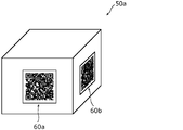
- FIG. 3 is a diagram showing an example of a marker 60 attached to the object 50a according to the present embodiment.
- the marker 60 is, for example, a QR code and is attached to the surface of the object 50a.
- FIG. 3 describes an example in which the object 50a is a rectangular parallelepiped for convenience.
- one or more markers 60a and 60b are attached to the object 50a.
- the markers 60a and 60b are attached to different surfaces among a plurality of surfaces constituting the object 50a.
- the markers 60a and 60b are attached at positions where the image pickup device 10 can take an image.
- the markers 60a and 60b may be attached to, for example, a flat surface portion of the object 50a.
- the QR code may not store any particular information, or may store information regarding the allowable displacement value.
- the markers 60a and 60b are configured so that, for example, the coordinates (three-dimensional coordinates) of four or more positions (detection points) can be acquired.
- the markers 60a and 60b may be attached to a curved surface portion of the object 50a or the like as long as the coordinates in the three-dimensional space can be detected. Further, a plurality of markers 60a and 60b may be attached to one plane. Further, each of the markers 60a and 60b may be provided corresponding to the measurement point of the object 50a. For example, when there are a plurality of displacement measurement points on the object 50a, the markers 60a and 60b may be attached around each of the plurality of measurement points.
- the shapes of the markers 60a and 60b are quadrangles (for example, squares), but are not limited to these, and may be, for example, pentagons or more polygons (for example, regular polygons).
- FIG. 4 is a flowchart showing the operation of the displacement measurement system 1 according to the present embodiment. Specifically, FIG. 4 is a flowchart showing the operation of the displacement measuring device 20. Further, steps S11 to S15 shown in FIG. 4 show the operation of the correction parameter calculation unit 110.
- the acquisition unit 111 acquires image data indicating an image from the image pickup device 10 (S11).
- the image includes a marker 60.
- the acquisition unit 111 may acquire at least one image data in step S11. Further, in order to measure the displacement, the acquisition unit 111 may acquire two or more image data captured at different timings in step S11.
- the acquisition unit 111 When a plurality of image data are acquired, the acquisition unit 111 outputs at least one image data to the position detection unit 112 and outputs two or more image data to the displacement detection unit 120.
- the acquisition unit 111 may output different image data to the position detection unit 112 and the displacement detection unit 120, or may output at least a part of the same image data.
- At least one image data output to the position detection unit 112 is an example of the first image data
- two or more image data output to the displacement detection unit 120 is an example of the second image data.
- step S11 is an example of the first acquisition step. Further, step S11 may be an example of a fourth acquisition step in the displacement amount calculation method described later.
- the acquisition unit 111 may function as a third acquisition unit for acquiring two or more second image data.
- Each of the first image data and the second image data is image data indicating an image captured under the same conditions such as camera parameters.
- the position detection unit 112 detects the marker 60 from the image data including the marker 60, and detects specific coordinates based on the detected marker 60 (S12).
- the position detection unit 112 detects, for example, the four corners of the marker 60, which is a QR code, and detects the coordinates of the four corners. In this way, the position detection unit 112 detects a plurality of coordinates in step S12. It can be said that the position detection unit 112 sets a plurality of coordinates based on the marker 60.
- the quadrangles (cutout symbols) at the four corners are detected in order to detect the position, outer shape, etc. of the QR code.
- an automatically detected position As a position for detecting specific coordinates, it is possible to omit the process of determining the position for detecting specific coordinates.
- FIG. 5 is a diagram for explaining the detection result of the position detection unit 112 according to the present embodiment.
- the "x" in the three-dimensional coordinates (x, y, z) shown below is x.
- the position on the axis is indicated, "y” indicates the position on the y-axis, and [z] indicates the position on the z-axis.
- the x-axis direction, the y-axis direction, and the z-axis direction are directions orthogonal to each other.
- the position detection unit 112 detects the detection points Q1 to Q4 at the four corners of the marker 60, and sets the coordinates for each of the detected detection points Q1 to Q4.
- the position detection unit 112 sets the coordinates based on the positional relationship between the detection points Q1 to Q4.
- the position detection unit 112 sets the coordinates, for example, based on the distance between the detection points Q1 and Q4 (for example, the distance between the detection points Q1 and Q2).
- the detection points Q1 to Q4 may be, for example, the four corners of the QR code which is a square.
- the first distance of the detection points Q1 and Q2, the second distance of the detection points Q2 and Q4, the third distance of the detection points Q4 and Q3, and the fourth distance of the detection points Q3 and Q1 are mutual. Equal, but not limited to.
- the position detection unit 112 sets the coordinates of other detection points according to the position (distance) from the detection point Q1 with reference to the coordinates. .. Since the position detection unit 112 has the same first to fourth distances, the coordinates of the detection point Q2 are set to (1, 0, 0), and the coordinates of the detection point Q3 are set to (0, 1, 0). Set and set the coordinates of the detection point Q4 to (1, 1, 0).
- the detection points Q1 and Q2 are the positions shown in FIG.
- the position detection unit 112 sets the coordinates of the detection point Q3 to (0, 2, 0). In this way, the position detection unit 112 sets the coordinates of each detection point according to the distance ratio (for example, the ratio of the actual size values).
- the position detection unit 112 may set the coordinates of each detection point according to the distance (number of pixels) between the detection points on the image, for example.
- the position detection unit 112 outputs coordinate information indicating specific coordinates to the position estimation unit 113.
- step S12 is an example of a detection step.
- the coordinate information is an example of the detection result.
- the position estimation unit 113 estimates the position of the image pickup device 10 based on the image data (position on the image data), the coordinate information, and the internal parameters of the image pickup device 10 (S13).
- the position estimation unit 113 solves the PnP problem (Perceptive-n-Point Problem) when the three-dimensional position of the object 50 (here, the three-dimensional position of the marker 60) and the internal parameters of the imaging device 10 are known.
- the position of the imaging device 10 can be estimated with.
- the position estimation unit 113 estimates the position of the image pickup apparatus 10 by solving the P4P problem.
- the position of the image pickup apparatus 10 here is represented as, for example, three-dimensional coordinates when the detection point Q1 is the origin.
- the position estimation unit 113 may further estimate the posture of the image pickup device 10 by solving the PnP problem.
- the position estimation unit 113 outputs position information indicating the estimated position of the imaging device 10 to the distance calculation unit 114.
- step S13 is an example of an estimation step.
- the distance calculation unit 114 calculates the distance from the image pickup device 10 to the object 50 based on the coordinate information and the position information (S14).
- the distance calculation unit 114 determines the distance from the image pickup device 10 to the object 50 based on the position (coordinates) of the image pickup device 10 included in the position information and the actual size length corresponding to the distance "1" at the coordinates. calculate.
- the position of the object 50 when viewed from the image pickup apparatus 10 is acquired.
- the actual length corresponding to the distance "1" on the coordinates may be stored in advance by the correction parameter calculation unit 110, may be acquired via the input device 40, or the marker 60 may be a QR code. In some cases, it may be stored in the QR code.
- the distance calculation unit 114 outputs distance information indicating the distance between the image pickup device 10 and the object 50 to the correction value calculation unit 115. Note that step S14 is an example of a distance calculation step.
- the correction value calculation unit 115 calculates a correction value for converting the pixel displacement amount into the actual size displacement amount based on the position and distance information of the image pickup device 10 and the internal parameters of the image pickup device 10 (S15).
- the correction value calculation unit 115 calculates one correction value for the object 50.
- the correction value includes, for example, information indicating an actual size value corresponding to one pixel at a measurement point.
- Step S15 is an example of the parameter calculation step. Further, step S15 may be an example of the third acquisition step.
- the correction parameter calculation unit 110 may calculate a correction value for each of the plurality of markers 60.
- the correction value can be calculated for each of the planes. It is possible to measure the actual size value of displacement with high accuracy.
- FIG. 6 is a diagram for explaining a method of converting the actual size of the displacement according to the present embodiment.
- FIG. 6 shows an example in which the object 50 is displaced in a direction parallel to the projection surface (imaging surface) of the imaging device 10.
- the position T (Tx, Ty, Tz) of the image pickup device 10 shown in FIG. 6 indicates the position of the lens 11 of the image pickup device 10, and the optical center O indicates the center of the lens 11 of the image pickup device 10 and the position P1 (x).
- Y indicate the position on the imaging surface corresponding to the position M1 (X, Y, Z) of the measurement point at the first time point of the object 50, and the displacement ( ⁇ x1, ⁇ y1) on the image is the first time point.
- the difference between the position P2 and the position P1 on the imaging surface corresponding to the position M2 of the measurement point at the second time point different from the above is shown.
- the displacement ( ⁇ x1, ⁇ y1) is the number of pixels on the image.
- the first time point is, for example, an initial time point when the object 50 is not displaced.
- the distance L2 between the optical center O and the position M1 is determined by the similarity between the triangle ⁇ OP1P2 and the triangle ⁇ OM1M2.
- the correction value calculation unit 115 calculates the correction value based on the above (Equation 2). From (Equation 2), the correction value for calculating the displacement Dx1 is L2 / L1. Further, from (Equation 2), the correction value for calculating the displacement Dy1 is also L2 / L1.
- the image center (cx, cy) and the focal length f are acquired as internal parameters of the image pickup apparatus 10.
- the correction value calculation unit 115 may calculate the internal parameters of the image pickup apparatus 10 using the chart image.
- the correction value calculation unit 115 outputs correction information indicating the calculated correction value to the displacement amount calculation unit 130.
- the displacement amount calculation unit 130 acquires correction information from the correction value calculation unit 115.
- the displacement amount calculation unit 130 functions as a second acquisition unit for acquiring correction parameters.
- the displacement detection unit 120 calculates the amount of pixel displacement of the displacement of the object 50 on the image data from the image data (S16).
- the displacement detection unit 120 calculates the pixel displacement amount from, for example, the displacement of the object 50 projected on the projection surface of the image pickup apparatus 10.
- the displacement detection unit 120 calculates, for example, how many pixels on the image the displacement at the measurement point is for each of a plurality of measurement points of the object 50.
- the displacement detection unit 120 outputs the calculated pixel displacement amount to the displacement amount calculation unit 130.
- the displacement amount calculation unit 130 calculates the actual size displacement amount based on the pixel displacement amount and the correction value (S17).
- the displacement amount calculation unit 130 calculates the actual size displacement amount at the measurement point by calculating the pixel displacement amount and the correction value at the measurement point for each of the plurality of measurement points of the object 50. In this way, the displacement amount calculation unit 130 functions as a conversion unit that converts the pixel displacement amount in the second or more second image data into the actual size displacement amount based on the correction information.
- the displacement amount calculation unit 130 outputs the presentation information including the calculated actual size displacement amount to the output device 30 (S18). Then, the output device 30 displays the presentation information acquired from the displacement amount calculation unit 130 as an image. Note that step S18 is an example of a conversion step.
- step S11 to step S15 shown in FIG. 4 may be performed every time the process of calculating the actual size displacement amount of the object 50 is executed, or the installation position, posture, and the image pickup device 10 of the image pickup apparatus 10 may be executed. It may be done every time at least one of the camera parameters (including internal parameters) is changed. Further, the correction value calculation unit 115 may store the calculated correction value in a storage unit (not shown). Then, when calculating the actual size displacement amount of the object 50, the correction value calculation unit 115 may read the correction value from the storage unit and output the read correction value to the displacement amount calculation unit 130. That is, the correction value calculation unit 115 may use the correction value calculated in the past as the correction value for calculating the current actual size displacement amount. As a result, the processing amount of the correction parameter calculation unit 110 can be reduced.
- the above steps S11 to S15 are processes executed in the correction parameter calculation method for calculating the correction parameter. Further, the above steps S16 to S18 are processes executed in the displacement amount calculation method for calculating the actual size displacement amount.
- the displacement amount calculation method may include the processes of steps S11 to S15.
- the displacement measurement system 1 includes an image pickup device 10 and a displacement measurement device 20 having a correction parameter calculation unit 110.
- the correction parameter calculation unit 110 estimates the position of the image pickup device 10 based on the marker 60 included in the image data acquired from the image pickup device 10, and converts the pixel displacement amount into the actual size displacement amount based on the position. Calculate the correction value.
- the correction value is calculated only by acquiring the image data including the marker 60 from the image pickup device 10 without using another device (for example, a distance measurement device). Therefore, the correction parameter can be easily calculated.
- the displacement measuring device 20 measures the actual size displacement amount of the displacement of the object 50 by using two or more image data captured by the imaging device 10. As a result, the displacement measuring device 20 can measure the actual size displacement amount even if the displacement of the object 50 is a vibration having a period that cannot be measured by using a laser range finder or the like.
- the displacement measurement system 1 according to this modification can accurately calculate the actual size displacement amount even when the displacement direction of the object 50 is different from the horizontal direction with the projection surface (imaging surface) of the imaging device. It is characterized by points.
- FIG. 7 is a flowchart showing the operation of the displacement measurement system 1 according to this modification.
- the correction value calculation unit 115 acquires the displacement direction information of the object 50 (S21).
- the correction value calculation unit 115 may acquire displacement direction information via, for example, the input device 40.
- the displacement direction information may be, for example, information indicating the displacement direction based on the drive direction of the drive unit of the motor when the object 50 is a motor.
- the displacement direction information may be information indicating the predicted displacement direction, for example, when the displacement direction of the object 50 can be predicted by design.
- the displacement direction information may be information indicating, for example, a direction (for example, a vertical direction) in which the object 50 is a bridge or the like and receives stress from a vehicle or the like.
- the displacement direction indicated by the displacement direction information is not limited to one, and may be two or more (two or more directions).
- Step S21 is an example of the second acquisition step.
- the displacement direction information is not limited to being acquired via the input device 40.
- the displacement direction information may be acquired based on the image data.
- the QR code may store information regarding the displacement direction of the object 50.
- the correction value calculation unit 115 may acquire the displacement direction of the object 50 based on the QR code included in the image data.
- the displacement direction is, for example, a direction based on the surface (plane) of the object 50 to which the QR code is attached.
- the correction value calculation unit 115 calculates a correction value for converting the pixel displacement amount into the actual size displacement amount based on the position and distance information of the image pickup device 10, the internal parameters of the image pickup device 10, and the displacement direction information. (S22). That is, the correction value calculation unit 115 calculates the correction value using the displacement direction information in addition to the embodiment. Note that step S22 is an example of a parameter calculation step.
- FIG. 8A is a diagram for explaining displacement correction in consideration of the displacement direction according to this modification.
- FIG. 8B is a second diagram for explaining the displacement correction in consideration of the displacement direction according to the present modification.
- 8A and 8B are bird's-eye views of the object 50b as viewed from above. The shape of the object 50b is square for convenience.
- the projection surface is Of the displacements of the object 50b, only the displacements in the direction parallel to the projection plane are projected.
- the displacement direction is the direction connecting the upper left and the lower right on the paper surface.
- the displacement of the measurement point of the object 50b is D1
- the displacement of the measurement point of the object 50b projected on the projection surface is D2.
- the displacement D2 is a component in the direction parallel to the projection plane in the displacement D1.
- the displacement direction is the direction connecting the lower left and the upper right on the paper.
- the displacement of the measurement point of the object 50b is D3
- the displacement of the measurement point of the object 50b projected on the projection surface is D4.
- the displacement D4 is a component in the direction parallel to the projection plane in the displacement D3.
- the displacements D1 and D3 are actual size displacement amounts, for example, actual size values.
- the displacements D2 and D4 are pixel displacement amounts, for example, the number of pixels.
- displacements D1 and D3 having different actual displacement directions may be detected as displacements in the same direction on the projection surface. With this, the displacement in the direction horizontal to the projection plane can be measured, but the displacement in the direction perpendicular to the projection plane cannot be measured.
- the correction value calculation unit 115 acquires the displacement direction information of the object 50 in step S21, and uses the displacement direction information in step S22 on the image data.
- a correction value for converting the pixel displacement amount of the object 50 into the actual size displacement amount is calculated.
- the correction value here includes an actual size value corresponding to one pixel and information indicating a displacement direction.
- the correction value may include, for example, information indicating an actual size value (Xa, Yb, Zc) corresponding to one pixel.
- the actual size value Xa indicates the actual size value of the displacement in the x-axis direction in the three-dimensional Cartesian coordinate system of the real space when the displacement is one pixel on the projection plane.
- the actual size value Xb indicates the actual size value of the displacement in the y-axis direction in the three-dimensional Cartesian coordinate system of the real space when the displacement is one pixel on the projection plane.
- Xc indicates the actual size value of the displacement in the z-axis direction in the three-dimensional Cartesian coordinate system in the real space when the displacement is one pixel on the projection plane.
- the actual size values (Xa, Yb, Zc) are examples of correction parameters.
- FIG. 9 is a diagram for explaining a method of converting the actual size of the displacement according to the present modification.
- the position P1 on the projection plane corresponding to the position M1 (X, Y, Z) of the measurement point at the first time point of the object 50 is (x, y)
- the distance L1 to P1 can be calculated by (Equation 1).
- the first time point is, for example, an initial time point when the object 50 is not displaced.
- the difference (displacement) between the position P3 and the position P1 on the projection plane corresponding to the position M3 of the measurement point at the second time point different from the first time point is ( ⁇ x2, ⁇ y2)
- the first correction value is It can be calculated by (Equation 2).
- the first correction value here is a value capable of calculating the actual size displacement amount of the displacement in the direction parallel to the projection surface of the image pickup apparatus 10.
- the first correction value is, for example, a value at which the displacement (Dx2, Dy2) of the actual size displacements (Dx2, Dy2, Dz2) can be calculated from the displacement ( ⁇ x2, ⁇ y2) on the image.
- the correction value calculation unit 115 converts the first correction value into a second correction value which is three-dimensional information based on the calculated first correction value and the displacement direction information.
- the correction value calculation unit 115 calculates a second correction value for converting the pixel displacement amount, which is two-dimensional information indicating the displacement on the projection surface, into the actual size displacement amount, which is three-dimensional information.
- the correction value calculation unit 115 may calculate the second correction value based on the first correction value and the angle formed by the projection surface and the displacement direction of the image pickup apparatus 10.
- the second correction value is, for example, a value capable of calculating the actual size displacement (Dx2, Dy2, Dz2) from the displacement ( ⁇ x2, ⁇ y2) on the image.
- the method by which the correction value calculation unit 115 calculates the second correction value is not limited to the above.
- the correction parameter calculation unit 110 of the displacement measurement system 1 further converts the pixel displacement amount into the actual size displacement amount by using the displacement direction information indicating the displacement direction of the object 50. Calculate the correction value of.
- the displacement measurement system 1 calculates a correction value using the displacement direction information when the object 50 is displaced in the direction intersecting the projection surface of the imaging device 10 when the object 50 is viewed from above. Therefore, the actual size value of the displacement can be measured with high accuracy.
- the image pickup device may be, for example, an image pickup device provided on a flying object such as a drone.
- the marker is a QR code or the like, and an example in which the marker is attached to the object has been described, but the present invention is not limited to this.
- the marker may be, for example, a pattern or characters provided on the surface of the object. Further, the marker may be, for example, an unevenness provided on the surface of the object. The distance between predetermined positions in patterns, characters, irregularities, etc. is known in advance. Further, the marker may be a sticker, a sticker, or the like whose size is known. For example, the marker may be a plain sticker of several cm square.
- the acquisition unit may be, for example, a connection unit to which a recording medium is connected.
- the connection unit may be, for example, a USB terminal to which a USB (Universal Serial Bus) is connected, an SD card slot into which an SD card is inserted, an optical drive into which an optical disk is inserted, or the like.
- USB Universal Serial Bus
- each step in the flowchart is executed is for exemplifying in order to specifically explain the present disclosure, and may be an order other than the above. Further, a part of the above steps may be executed at the same time (parallel) as other steps.
- the division of the functional block in the block diagram is an example, and a plurality of functional blocks can be realized as one functional block, one functional block can be divided into a plurality of functional blocks, and some functions can be transferred to other functional blocks. You may. Further, the functions of a plurality of functional blocks having similar functions may be processed by a single hardware or software in parallel or in a time division manner.
- the correction parameter calculation device in the above-described embodiment or the like may be realized by a single device, or may be realized by a plurality of devices connected to each other.
- the components included in the correction parameter calculation device may be distributed to the plurality of devices in any way.
- the displacement measuring device does not have an output device, that is, the displacement measuring device and the output device are separate bodies, but the displacement measuring device has an output device. You may.
- the output device functions as an output unit (for example, a display unit) that is a part of the displacement measuring device.
- the communication method between the devices provided in the displacement measurement system according to the above embodiment is not particularly limited. Wireless communication may be performed or wired communication may be performed between the devices. Further, wireless communication and wired communication may be combined between the devices.
- a part or all of the components included in the calculation device in the above embodiment or the like may be composed of one system LSI (Large Scale Integration: large-scale integrated circuit).
- a system LSI is an ultra-multifunctional LSI manufactured by integrating a plurality of processing units on a single chip. Specifically, a microprocessor, a ROM (Read Only Memory), a RAM (Random Access Memory), etc. It is a computer system composed of. A computer program is stored in the ROM. The system LSI achieves its function by operating the microprocessor according to the computer program.
- system LSI Although it is referred to as a system LSI here, it may be referred to as an IC, an LSI, a super LSI, or an ultra LSI due to the difference in the degree of integration. Further, the method of making an integrated circuit is not limited to LSI, and may be realized by a dedicated circuit or a general-purpose processor. An FPGA (Field Programmable Gate Array) that can be programmed after the LSI is manufactured, or a reconfigurable processor that can reconfigure the connection and settings of the circuit cells inside the LSI may be used.
- FPGA Field Programmable Gate Array
- all or part of the above-mentioned various processes may be realized by hardware such as an electronic circuit or may be realized by software.
- the processing by the software is realized by the processor included in the displacement measuring device executing the program stored in the memory.
- one aspect of the present disclosure may be a computer program that causes a computer to execute each characteristic step included in the correction parameter calculation method and the displacement amount calculation method.
- one aspect of the present disclosure may be a computer-readable, non-temporary recording medium on which such a program is recorded.
- such a program may be recorded on a recording medium and distributed or distributed. For example, by installing the distributed program on a device having another processor and causing the processor to execute the program, it is possible to cause the device to perform each of the above processes.
- the present disclosure can be widely used as a device for measuring the actual size value of displacement in the displacement measurement of an object using an image.
- Displacement measurement system 10 Imaging device 11 Lens 20 Displacement measurement device 30 Output device 40 Input device 50, 50a, 50b Object 60, 60a, 60b Marker 110 Correction parameter calculation unit (correction parameter calculation device) 111 Acquisition section (1st acquisition section) 112 Position detection unit 113 Position estimation unit 114 Distance calculation unit 115 Correction value calculation unit (parameter calculation unit) 120 Displacement detection unit 130 Displacement amount calculation unit (conversion unit) f Focal length L1, L2 Distance M1 to M3, P1 to P3, T position O Optical center Q1 to Q4 Detection point
Landscapes
- Physics & Mathematics (AREA)
- General Physics & Mathematics (AREA)
- Engineering & Computer Science (AREA)
- Electromagnetism (AREA)
- Radar, Positioning & Navigation (AREA)
- Remote Sensing (AREA)
- Computer Vision & Pattern Recognition (AREA)
- Health & Medical Sciences (AREA)
- Toxicology (AREA)
- Artificial Intelligence (AREA)
- General Health & Medical Sciences (AREA)
- Theoretical Computer Science (AREA)
- Length Measuring Devices By Optical Means (AREA)
- Measurement Of Optical Distance (AREA)
Priority Applications (3)
| Application Number | Priority Date | Filing Date | Title |
|---|---|---|---|
| JP2021552097A JP7489671B2 (ja) | 2019-10-17 | 2020-06-26 | 補正パラメータ算出方法、変位量算出方法、補正パラメータ算出装置、及び、変位量算出装置 |
| CN202080066802.6A CN114502913B (zh) | 2019-10-17 | 2020-06-26 | 修正参数计算方法及装置、位移量计算方法及装置 |
| US17/699,418 US11920913B2 (en) | 2019-10-17 | 2022-03-21 | Conversion parameter calculation method, displacement amount calculation method, conversion parameter calculation device, and displacement amount calculation device |
Applications Claiming Priority (2)
| Application Number | Priority Date | Filing Date | Title |
|---|---|---|---|
| JP2019-190126 | 2019-10-17 | ||
| JP2019190126 | 2019-10-17 |
Related Child Applications (1)
| Application Number | Title | Priority Date | Filing Date |
|---|---|---|---|
| US17/699,418 Continuation US11920913B2 (en) | 2019-10-17 | 2022-03-21 | Conversion parameter calculation method, displacement amount calculation method, conversion parameter calculation device, and displacement amount calculation device |
Publications (1)
| Publication Number | Publication Date |
|---|---|
| WO2021075090A1 true WO2021075090A1 (ja) | 2021-04-22 |
Family
ID=75537583
Family Applications (1)
| Application Number | Title | Priority Date | Filing Date |
|---|---|---|---|
| PCT/JP2020/025232 Ceased WO2021075090A1 (ja) | 2019-10-17 | 2020-06-26 | 補正パラメータ算出方法、変位量算出方法、補正パラメータ算出装置、及び、変位量算出装置 |
Country Status (4)
| Country | Link |
|---|---|
| US (1) | US11920913B2 (https=) |
| JP (1) | JP7489671B2 (https=) |
| CN (1) | CN114502913B (https=) |
| WO (1) | WO2021075090A1 (https=) |
Cited By (3)
| Publication number | Priority date | Publication date | Assignee | Title |
|---|---|---|---|---|
| EP4113053A1 (en) * | 2021-07-02 | 2023-01-04 | Realook & Company Co., Ltd. | Apparatus for correcting assembly deviation and process error thereof using sensing mark, and method of correcting assembly deviation and process error using same |
| KR20230069328A (ko) * | 2021-11-12 | 2023-05-19 | 주식회사 아이쉐어넷 | 거리 측정 장치 및 방법 |
| KR20240096145A (ko) * | 2022-12-19 | 2024-06-26 | 성균관대학교산학협력단 | 영상처리 기반 교량받침 3차원 변위측정 시스템 및 방법, 그리고 기록 매체 |
Families Citing this family (2)
| Publication number | Priority date | Publication date | Assignee | Title |
|---|---|---|---|---|
| SE546659C2 (en) * | 2022-11-01 | 2025-01-07 | Optiload Tech Ab | A displacement measuring method for measuring a displacement of an object to be measured |
| CN117115270B (zh) * | 2023-08-31 | 2025-09-26 | 深圳市亿图视觉自动化技术有限公司 | 一种视觉相机的标定方法、装置、设备及存储介质 |
Citations (5)
| Publication number | Priority date | Publication date | Assignee | Title |
|---|---|---|---|---|
| JP2007296248A (ja) * | 2006-05-02 | 2007-11-15 | Sony Computer Entertainment Inc | ゲーム装置 |
| JP2013124972A (ja) * | 2011-12-15 | 2013-06-24 | Samsung Yokohama Research Institute Co Ltd | 位置推定装置及び方法、並びにテレビジョン受信機 |
| JP2015055969A (ja) * | 2013-09-11 | 2015-03-23 | 学校法人常翔学園 | 移動ロボット、移動ロボット制御システム、制御図形の表示されたシート、及びプログラム |
| JP2016071663A (ja) * | 2014-09-30 | 2016-05-09 | 株式会社Nttドコモ | 情報通信システムおよび情報読取方法 |
| JP2017215306A (ja) * | 2016-02-24 | 2017-12-07 | パナソニックIpマネジメント株式会社 | 変位検出装置および変位検出方法 |
Family Cites Families (18)
| Publication number | Priority date | Publication date | Assignee | Title |
|---|---|---|---|---|
| JP3672371B2 (ja) * | 1996-02-23 | 2005-07-20 | 松下電器産業株式会社 | 撮像手段による実空間長測定方法及び光学系の校正方法、並びに光学系の校正に用いる基準ゲージ |
| KR100458290B1 (ko) * | 2001-12-27 | 2004-12-03 | 고속도로관리공단 | 이미지 프로세싱을 이용한 구조물의 변위량 측정방법 |
| JP4234059B2 (ja) * | 2003-06-06 | 2009-03-04 | 三菱電機株式会社 | カメラキャリブレーション方法およびカメラキャリブレーション装置 |
| JP5281610B2 (ja) | 2010-05-14 | 2013-09-04 | 西日本旅客鉄道株式会社 | レーザー距離計付き撮影装置 |
| JP5222430B1 (ja) * | 2012-10-19 | 2013-06-26 | 株式会社イノテック | 寸法計測装置、寸法計測方法及び寸法計測装置用のプログラム |
| CN103455993B (zh) * | 2013-09-30 | 2016-09-21 | 电子科技大学 | 一种自动视觉检测中基于光栅定位的二维图像拼接方法 |
| CN106687878B (zh) * | 2014-10-31 | 2021-01-22 | 深圳市大疆创新科技有限公司 | 用于利用视觉标记进行监视的系统和方法 |
| JP6521645B2 (ja) * | 2015-01-23 | 2019-05-29 | シャープ株式会社 | 画像計測装置 |
| CN106373156A (zh) * | 2015-07-20 | 2017-02-01 | 小米科技有限责任公司 | 通过图像确定空间参数的方法、装置及终端设备 |
| CN108603744B (zh) * | 2016-02-04 | 2020-06-16 | 富士胶片株式会社 | 信息处理装置、信息处理方法及程序 |
| US10062176B2 (en) | 2016-02-24 | 2018-08-28 | Panasonic Intellectual Property Management Co., Ltd. | Displacement detecting apparatus and displacement detecting method |
| WO2017169365A1 (ja) * | 2016-03-29 | 2017-10-05 | Kyb株式会社 | 路面変位検出装置およびサスペンション制御方法 |
| WO2017183211A1 (ja) * | 2016-04-22 | 2017-10-26 | 株式会社ニコン | 画像測定方法、画像測定プログラム及び画像測定装置、並びに物品の製造方法 |
| WO2018124188A1 (ja) | 2016-12-27 | 2018-07-05 | Coaido株式会社 | 測定装置およびプログラム |
| WO2018158994A1 (ja) * | 2017-02-28 | 2018-09-07 | パナソニックIpマネジメント株式会社 | 変位計測装置および変位計測方法 |
| EP3591370B1 (en) * | 2017-02-28 | 2021-08-25 | Panasonic Intellectual Property Management Co., Ltd. | Monitoring system |
| JP6967715B2 (ja) * | 2017-04-18 | 2021-11-17 | パナソニックIpマネジメント株式会社 | カメラ校正方法、カメラ校正プログラム及びカメラ校正装置 |
| US20210097707A1 (en) * | 2018-03-23 | 2021-04-01 | Sony Corporation | Information processing device, movement device, and method, and program |
-
2020
- 2020-06-26 JP JP2021552097A patent/JP7489671B2/ja active Active
- 2020-06-26 WO PCT/JP2020/025232 patent/WO2021075090A1/ja not_active Ceased
- 2020-06-26 CN CN202080066802.6A patent/CN114502913B/zh active Active
-
2022
- 2022-03-21 US US17/699,418 patent/US11920913B2/en active Active
Patent Citations (5)
| Publication number | Priority date | Publication date | Assignee | Title |
|---|---|---|---|---|
| JP2007296248A (ja) * | 2006-05-02 | 2007-11-15 | Sony Computer Entertainment Inc | ゲーム装置 |
| JP2013124972A (ja) * | 2011-12-15 | 2013-06-24 | Samsung Yokohama Research Institute Co Ltd | 位置推定装置及び方法、並びにテレビジョン受信機 |
| JP2015055969A (ja) * | 2013-09-11 | 2015-03-23 | 学校法人常翔学園 | 移動ロボット、移動ロボット制御システム、制御図形の表示されたシート、及びプログラム |
| JP2016071663A (ja) * | 2014-09-30 | 2016-05-09 | 株式会社Nttドコモ | 情報通信システムおよび情報読取方法 |
| JP2017215306A (ja) * | 2016-02-24 | 2017-12-07 | パナソニックIpマネジメント株式会社 | 変位検出装置および変位検出方法 |
Cited By (5)
| Publication number | Priority date | Publication date | Assignee | Title |
|---|---|---|---|---|
| EP4113053A1 (en) * | 2021-07-02 | 2023-01-04 | Realook & Company Co., Ltd. | Apparatus for correcting assembly deviation and process error thereof using sensing mark, and method of correcting assembly deviation and process error using same |
| KR20230069328A (ko) * | 2021-11-12 | 2023-05-19 | 주식회사 아이쉐어넷 | 거리 측정 장치 및 방법 |
| KR102679383B1 (ko) * | 2021-11-12 | 2024-06-28 | 주식회사 아이쉐어넷 | 거리 측정 장치 및 방법 |
| KR20240096145A (ko) * | 2022-12-19 | 2024-06-26 | 성균관대학교산학협력단 | 영상처리 기반 교량받침 3차원 변위측정 시스템 및 방법, 그리고 기록 매체 |
| KR102919227B1 (ko) | 2022-12-19 | 2026-01-27 | 성균관대학교산학협력단 | 영상처리 기반 교량받침 3차원 변위측정 시스템 및 방법, 그리고 기록 매체 |
Also Published As
| Publication number | Publication date |
|---|---|
| CN114502913B (zh) | 2025-12-19 |
| JPWO2021075090A1 (https=) | 2021-04-22 |
| JP7489671B2 (ja) | 2024-05-24 |
| US11920913B2 (en) | 2024-03-05 |
| CN114502913A (zh) | 2022-05-13 |
| US20220205776A1 (en) | 2022-06-30 |
Similar Documents
| Publication | Publication Date | Title |
|---|---|---|
| JP7489671B2 (ja) | 補正パラメータ算出方法、変位量算出方法、補正パラメータ算出装置、及び、変位量算出装置 | |
| CN114450552B (zh) | 校正参数计算方法、位移量计算方法、校正参数计算装置及位移量计算装置 | |
| CN108074267B (zh) | 交点检测装置及方法、摄像头校正系统及方法及记录介质 | |
| CN109920004B (zh) | 图像处理方法、装置、标定物组合、终端设备及标定系统 | |
| JP2014131257A (ja) | 画像補正システム、画像補正方法及びプログラム | |
| JP2017182695A (ja) | 情報処理プログラム、情報処理方法および情報処理装置 | |
| CN109918977A (zh) | 确定空闲车位的方法、装置及设备 | |
| CN112292577B (zh) | 三维测量装置以及方法 | |
| CN109920003A (zh) | 相机标定检测方法、装置以及设备 | |
| JP2011155412A (ja) | 投影システムおよび投影システムにおける歪み修正方法 | |
| CN114979618B (zh) | 计测系统及记录有计测程序的记录介质 | |
| JP4250620B2 (ja) | 情報処理方法および装置 | |
| JPWO2010013289A1 (ja) | カメラ校正画像作成装置およびカメラ校正画像作成プログラム | |
| JP2018009927A (ja) | 画像処理装置、画像処理方法及びプログラム | |
| JPWO2016194078A1 (ja) | 情報処理装置 | |
| CN116608837B (zh) | 测量系统、测量方法以及存储介质 | |
| JP6906177B2 (ja) | 交点検出装置、カメラ校正システム、交点検出方法、カメラ校正方法、プログラムおよび記録媒体 | |
| CN119856501A (zh) | 摄像机校正装置及摄像机校正方法 | |
| CN120530647A (zh) | 图像点群数据处理装置、图像点群数据处理方法和图像点群数据处理程序 | |
| JP2023121596A (ja) | カメラのパラメーター算出方法、及びカメラシステム | |
| JP6779368B2 (ja) | 画像処理装置、画像処理方法、およびプログラム | |
| CN115829850B (zh) | 图像校正方法、系统、内储程序的计算机可读记录媒体以及程序产品 | |
| CN119359822B (zh) | 对准相机和量测相机的相对位置标定方法及相关装置 | |
| CN120869557B (zh) | 一种光学镜头的光轴倾角测定方法、装置、设备及介质 | |
| JP2005251122A (ja) | 画像処理装置および画像処理方法 |
Legal Events
| Date | Code | Title | Description |
|---|---|---|---|
| 121 | Ep: the epo has been informed by wipo that ep was designated in this application |
Ref document number: 20875683 Country of ref document: EP Kind code of ref document: A1 |
|
| ENP | Entry into the national phase |
Ref document number: 2021552097 Country of ref document: JP Kind code of ref document: A |
|
| NENP | Non-entry into the national phase |
Ref country code: DE |
|
| 122 | Ep: pct application non-entry in european phase |
Ref document number: 20875683 Country of ref document: EP Kind code of ref document: A1 |