WO2021070736A1 - 建設機械 - Google Patents
建設機械 Download PDFInfo
- Publication number
- WO2021070736A1 WO2021070736A1 PCT/JP2020/037478 JP2020037478W WO2021070736A1 WO 2021070736 A1 WO2021070736 A1 WO 2021070736A1 JP 2020037478 W JP2020037478 W JP 2020037478W WO 2021070736 A1 WO2021070736 A1 WO 2021070736A1
- Authority
- WO
- WIPO (PCT)
- Prior art keywords
- hydraulic pump
- hydraulic
- tilt
- pump
- flow rate
- Prior art date
- Legal status (The legal status is an assumption and is not a legal conclusion. Google has not performed a legal analysis and makes no representation as to the accuracy of the status listed.)
- Ceased
Links
Images


Classifications
-
- E—FIXED CONSTRUCTIONS
- E02—HYDRAULIC ENGINEERING; FOUNDATIONS; SOIL SHIFTING
- E02F—DREDGING; SOIL-SHIFTING
- E02F9/00—Component parts of dredgers or soil-shifting machines, not restricted to one of the kinds covered by groups E02F3/00 - E02F7/00
- E02F9/26—Indicating devices
-
- F—MECHANICAL ENGINEERING; LIGHTING; HEATING; WEAPONS; BLASTING
- F04—POSITIVE - DISPLACEMENT MACHINES FOR LIQUIDS; PUMPS FOR LIQUIDS OR ELASTIC FLUIDS
- F04B—POSITIVE-DISPLACEMENT MACHINES FOR LIQUIDS; PUMPS
- F04B51/00—Testing machines, pumps, or pumping installations
-
- F—MECHANICAL ENGINEERING; LIGHTING; HEATING; WEAPONS; BLASTING
- F15—FLUID-PRESSURE ACTUATORS; HYDRAULICS OR PNEUMATICS IN GENERAL
- F15B—SYSTEMS ACTING BY MEANS OF FLUIDS IN GENERAL; FLUID-PRESSURE ACTUATORS, e.g. SERVOMOTORS; DETAILS OF FLUID-PRESSURE SYSTEMS, NOT OTHERWISE PROVIDED FOR
- F15B20/00—Safety arrangements for fluid actuator systems; Applications of safety devices in fluid actuator systems; Emergency measures for fluid actuator systems
Definitions
- the present invention relates to a construction machine such as a hydraulic excavator or a crane equipped with a one-sided tilt type variable displacement hydraulic pump.
- Patent Document 1 is known as a method for diagnosing a failure of a conventional pump.
- the pump tilt amount is increased with the hydraulic circuit of the hydraulic pump closed, and the pump tilt amount when the discharge pressure of the hydraulic pump reaches the set pressure is compared with the failure determination value.
- the amount of tilt of the pump is equal to or greater than the failure judgment value, a failure signal is output, so there is no need to bother to disconnect the hydraulic piping and install a hydraulic tester, and failure diagnosis can be performed automatically and quickly at all times. ..
- the discharge flow rate of the pump is increased with the hydraulic circuit closed, and the pump tilt amount when the discharge pressure of the hydraulic pump reaches the set pressure is compared with the failure determination value.
- the pump discharge flow rate is equal to or higher than the failure judgment value, a failure signal is output, so it is considered that it is not necessary to rearrange the hydraulic circuit etc. and it can be dealt with automatically and quickly, but like a construction machine. There are cases where it cannot be applied to devices that use multiple pumps.
- the pump discharge amount can be set to zero, but in a construction machine such as a hydraulic excavator, in order to drive a single rod cylinder, one piece has an open circuit configuration. In most cases, a tilting pump is used.
- ⁇ Since the direction switching valve is located between the pump and the actuator, it is not necessary to reduce the tilt amount to zero. ⁇ A certain amount of pump flow rate is required even when the actuator is not operating to ensure responsiveness when the actuator is started. ⁇ Since a certain amount of pump flow rate is required for lubrication and cooling of circuit equipment installed downstream of the pump, a certain amount of flow rate (hereinafter referred to as standby flow rate) is maintained even when the lever is neutral, such as when the actuator is not operating. It is usually configured to discharge from a tilting pump. The minimum tilt amount of the one-side tilt pump is determined according to this standby flow rate.
- the standby flow rate is set to about 1/5 of the maximum discharge flow rate, and the maximum discharge flow rate is 200 L / min, the standby flow rate is also about 40 L / min.
- the one-sided tilting pump is not configured to discharge a minute flow rate, even if the diagnostic method of Patent Document 1 is applied to a system using the one-sided tilting pump, a minute leakage flow rate is applied. Cannot be detected or evaluated.
- the present invention comprises a prime mover, a tank for storing hydraulic oil, and a unilateral tilting variable displacement hydraulic pump driven by the prime mover and discharging hydraulic oil sucked from the tank.
- a direction switching that is connected to a plurality of hydraulic actuators and a discharge oil passage to which the discharge oil of the hydraulic pump is supplied and controls the flow of hydraulic oil supplied from the hydraulic pump to at least a part of the plurality of hydraulic actuators.
- the controller includes a pressure sensor for detecting the discharge pressure of the hydraulic pump, and the controller is the discharge oil passage.
- the rotation speed of the prime mover is changed so that the load can be operated.
- the discharge pressure of the hydraulic pump is measured, and the leakage flow rate of the hydraulic pump is calculated based on the rotation speed of the prime mover and the tilt for diagnosis when the discharge pressure of the hydraulic pump reaches a predetermined pressure.
- the communication between the discharge oil passage of the hydraulic pump and the tank is cut off, and the tilt of the hydraulic pump is held at the diagnostic tilt smaller than the standby tilt.
- It is a functional block diagram of the controller shown in FIG. It is a figure which shows the measurement flow of the pump leakage flow rate executed by the controller shown in FIG.
- It is a circuit diagram of the hydraulic drive device in the 2nd Example of this invention.
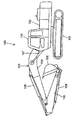
- FIG. 1 is a side view of the hydraulic excavator according to the first embodiment of the present invention.
- the hydraulic excavator 100 includes a traveling body 101, a swivel body 102 rotatably mounted on the traveling body 101, and a working device 103 rotatably mounted on the front side of the swivel body 102 in the vertical direction. And have.
- the working device 103 includes a boom 104 rotatably attached to the front side of the swivel body 102 in the vertical direction, an arm 105 rotatably attached to the tip of the boom 104 in the vertical or vertical direction, and the arm.
- a bucket 106 that is rotatably attached to the tip of the 105 in the vertical or front-rear direction is provided.
- the boom 104 is driven by the boom cylinder 107, which is a hydraulic actuator
- the arm 105 is driven by the arm cylinder 108, which is a hydraulic actuator
- the bucket 106 is driven by the bucket cylinder 109, which is a hydraulic actuator.
- a driver's cab 110 on which the operator is boarded is provided on the front side of the swivel body 102.
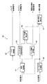
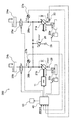
- the hydraulic drive system 200 includes an engine 20 as a prime mover, a one-sided tilt type variable displacement hydraulic pump 21 driven by the engine 20, and a pump push-out volume of the hydraulic pump 21 (hereinafter, pump tilt).
- a hydraulic pilot type tilt control device 22 that controls qp, and an electromagnetic proportional valve 23 that outputs the pilot pressure generated by reducing the primary pressure from the pilot hydraulic source (not shown) to the tilt control device 22.
- the direction switching valve unit 24 is connected to a discharge oil passage (hereinafter, pump discharge oil passage) 28 connected to the discharge port of the hydraulic pump 21, and is connected to the hydraulic pump 21 in response to an operation of an operating device (not shown). It controls the flow of pressure oil supplied to the hydraulic actuators 107 to 109.
- pump discharge oil passage hereinafter, pump discharge oil passage
- the bleed-off closing valve 25 is provided on the upstream side of the direction switching valve unit 24 of the pump discharge oil passage 28, opens and closes in response to a control signal from the controller 40, and communicates or shuts off the pump discharge oil passage 28.
- Pp pressure in the pump discharge oil passage 28
- Pr pressure in the pump discharge oil passage 28
- the pressure sensor 27 is provided on the upstream side of the bleed-off closing valve 25 of the pump discharge oil passage 28, converts the pressure of the pump discharge oil passage 28 (pump discharge pressure Pp) into a pressure signal, and outputs it to the controller 40.
- the controller 40 receives a command for measuring the pump leakage flow rate, controls the bleed-off closing valve 25, the engine rotation speed (hereinafter referred to as engine rotation speed) Neng, and the pump tilt qp, and discharges the pump detected by the pressure sensor 27.
- the leakage flow rate Qleak of the hydraulic pump 21 is calculated based on the pressure Pp.
- Axial piston type pumps are often used as hydraulic pumps for construction machinery, and there are diagonal shaft type and swash plate type as variable capacitance mechanism. In both cases, the variable capacitance is realized by changing the stroke process of the piston to change the push-out volume.
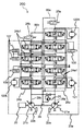
- variable displacement oblique shaft hydraulic pump 21 As an example of the unilateral tilt type variable displacement hydraulic pump 21, the structure of the variable displacement oblique shaft hydraulic pump is shown in FIG.
- the tubular casing 1 is composed of a substantially cylindrical casing main body 1A having a bearing portion on one end side and a head casing 1B in which the other end side of the casing main body 1A is closed.
- the rotating shaft 2 is rotatably provided in the casing body 1A.
- the cylinder block 3 is located in the casing body 1A and rotates together with the rotating shaft 2.
- a plurality of cylinders 4 are bored in the cylinder block 3 in the axial direction thereof.
- a piston 5 is slidably provided in each cylinder 4, and a connecting rod 6 is attached to each piston 5.
- a spherical portion 6A is formed at the tip of each connecting rod 6, and each spherical portion 6A is swingably supported by a drive disk 7 formed at the tip of the rotating shaft 2.
- the cylinder block 3 is arranged together with the valve plate 8 described later with a tilt angle ⁇ as a tilt amount with respect to the rotation shaft 2, and the pump push-off capacity is determined by this tilt angle ⁇ .
- the cylinder block 3 is in sliding contact with the one side end surface of the valve plate 8, and the other side end surface of the valve plate 8 is in sliding contact with the concavely curved tilting sliding surface 9 formed in the head casing 1B.
- a through hole 8A is bored in the center of the valve plate 8, and the tip portions of the center shaft 10 and the swing pin 15, which will be described later, are inserted into the through hole 8A from both sides.
- a pair of supply / discharge ports (not shown) that intermittently communicate with each cylinder 4 when the cylinder block 3 rotates are bored in the valve plate 8 and opens to the tilting sliding surface 9 of the head casing 1B.
- a pair of supply / discharge passages (not shown) communicate with these supply / discharge ports regardless of the tilt position (tilt angle ⁇ ) of the valve plate 8.
- the center shaft 10 supports the cylinder block 3 between the drive disk 7 and the valve plate 8.
- a spherical portion 10A is formed on one end side of the center shaft 10, and the spherical portion 10A is swingably supported at the axial center position of the drive disk 7.
- the other end side of the center shaft 10 protruding through the center of the cylinder block 3 is slidably inserted into the through hole 8A of the valve plate 8 so that the cylinder block 3 is centered with respect to the valve plate 8. It has become.
- the tilting mechanism 11 tilts the valve plate 8 along the tilting sliding surface 9.
- the tilting mechanism 11 is slidably inserted into the cylinder chamber 12 which is formed in the head casing 1B and has oil passage holes 12A and 12B on both ends in the axial direction, and is slidably inserted in the cylinder chamber 12.
- the servo piston 14 defining the hydraulic chambers 13A and 13B and the base end side are fixed to the servo piston 14, and the tip side becomes a spherical tip portion 15A and is swingably inserted into the through hole 8A of the valve plate 8. It is composed of a swing pin 15 and a cylinder.
- the control unit 16 tilts and controls the valve plate 8 via the tilting mechanism 11.
- the control unit 16 is provided on the outside of the head casing 1B, and includes a throttle switching valve (neither shown) that feedback-controls the amount of pressure oil supplied / discharged from the pilot pump (pilot pressure).
- a sleeve (not shown) is provided on the throttle switching valve, and the sleeve and the servo piston 14 are integrally connected by a feedback pin 17 inserted into a long hole 1C of the head casing 1B.
- the pressure oil (piston pressure) corresponding to the switching operation amount at this time is tilted from the pilot pump via the oil passage holes 12A and 12B.
- the servo piston 14 is supplied and discharged into the hydraulic chambers 13A and 13B of the rolling mechanism 11, and the servo piston 14 is slidably displaced by the pressure difference between the hydraulic chambers 13A and 13B, so that the servo piston 14 is valved via the swing pin 15.
- the plate 8 and the cylinder block 3 are tilted in the direction of arrow A with a tilt angle ⁇ .
- the sleeve of the throttle switching valve is displaced according to the displacement of the servo piston 14, so that the pressure oil amount from the pilot pump is feedback-controlled, and the displacement amount of the servo piston 14 is the switching operation amount of the throttle switching valve. Hold in the state corresponding to.
- the swash plate or the swash plate tilt amount (hereinafter referred to as tilt) can be changed in the swash plate pump to change the tilt amount per rotation.
- the discharge flow rate of the pump can be made variable by changing the amount of push-out of the piston. Therefore, it is possible to control the pump discharge amount by controlling the tilt amount of the swash plate or the swash plate, and the posture of the pump mechanism is controlled.
- the double tilt type pump it is necessary for the double tilt type pump to swing the tilt angle in both directions, which may increase the functional aspect, and the structure is significantly different and the number of parts increases, which is cost effective. Will also be expensive.
- the double tilt type pump has poor suction performance and is not preferable in terms of use, and a charge circuit is required for circulation and lubrication of oil to the auxiliary device. Therefore, it is not practical to use a double tilt pump in one tilt, and it is natural to use a single tilt pump type if the machine meets the specifications with a single tilt pump such as a shovel. It has become.
- Qpref Theoretical pump discharge flow rate
- Qleak Pump leak flow rate
- Qrelief Relief flow rate
- Qcb Center bypass flow rate (bleed-off flow rate)
- B Volume modulus
- V Pump discharge volume
- the pump discharge pressure Pp when the pump discharge pressure Pp is lower than the relief set pressure Pr, the relief flow rate Qrelief becomes zero. Further, when the bleed-off closing valve 25 is closed, the center bypass flow rate Qcb becomes zero. Further, when the pump discharge pressure Pp is stable, the rate of change dPp / dt of the pump discharge pressure Pp becomes sufficiently small. In such a circuit state, the theoretical pump discharge flow rate Qpref is equal to the pump leak flow rate Qleak. Therefore, the pump leakage flow rate Qleak can be measured by calculating the theoretical pump discharge flow rate Qpref in such a circuit state.
- Patent Document 1 targets a double tilting pump, the pump discharge flow rate can be freely changed from zero.
- the standby flow rate of the single tilting pump described above is 50 L / min
- This is equivalent to 5 times the pump tilt (5 cm 3 / rev) for measuring the leak flow rate of 5%.
- the standby tilt is the minimum tilt
- the discharge flow rate of the one-side tilt type pump cannot be reduced to the equivalent of a leakage flow rate of 5%.
- the minimum tilt of the pump is configured to be switched between normal operation and leak diagnosis as follows.
- the diagnostic tilt qpd satisfies the following conditions with respect to the minimum engine speed Neng_min (usually idling speed) and the measurable minimum leakage flow rate Qleak_min that can be operated under hydraulic load of construction machinery. There is a need.
- the pump discharge flow rate can be suppressed to the minimum leakage flow rate Qleak_min or less by lowering the engine speed Neng to the minimum rotation speed Neng_min, so the minimum leakage flow rate Qleak_min is measured. It becomes possible to do.
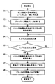
- FIG. 4 shows the functional block of the controller 40. In FIG. 4, only the configuration related to the measurement of the leakage flow rate of the hydraulic pump 21 is shown, and the configuration related to the driving of the actuators 107 to 109 is omitted.
- the hydraulic pump 21 is in a state where the communication between the discharge oil passage 28 of the hydraulic pump 21 and the tank 29 is cut off (a state in which the bleed-off flow rate and the relief flow rate are zero).
- the tilt qp was held in the diagnostic tilt qpd smaller than the standby tilt qps, the flow rate Neng of the prime mover 20 was raised from the minimum flow rate Neng_min, and the discharge pressure Pp of the hydraulic pump 21 reached a predetermined pressure Ps.
- the leakage flow rate Qleak of the hydraulic pump 21 can be measured in a minute flow rate range smaller than the standby flow rate. As a result, the predictive diagnosis of the hydraulic pump 21 becomes possible.
- the bleed-off closing valve 25 (shown in FIG. 2) provided on the upstream side of the directional control valve unit 24, the bleed-off closing valve provided on the downstream side of the directional switching valve units 24a and 24b It differs from the first embodiment in that it includes 25a and 25b.
- directional switching valves 24a1, 24b1 for controlling the flow of pressure oil supplied to the actuator are provided in parallel with the supply ports of each pump, and from these directional switching valves 24a1, 24b1.
- the leakage of pressure oil affects the drive of the actuator in the same way as the leakage of the pump.
- the total flow rate of the pump leakage flow rate Qleak and the direction switching valve leakage flow rate Qcv is calculated as the theoretical pump discharge flow rate Qpref, and the entire pressure oil supply system including the hydraulic pumps 21a and 21b and the direction switching valve units 24a and 24b It is possible to measure the leakage flow rate of.
- the leakage flow rate of the entire pressure oil supply system can be measured from a minute flow rate region, the bleed-off flow rate is zero, and the relief flow rate is reduced.
- the leakage flow rate of the pressure oil supply system is accurately measured through the theoretical pump discharge flow rate Qleak when the pump discharge pressure gradually exceeds the threshold (30 MPa) under the condition of zero, and the pressure oil supply of construction machinery is supplied. It becomes possible to evaluate the degree of damage as a source.
- the hydraulic excavator 100 in this embodiment is provided on bypass lines 60a and 60b connecting the direction switching valve units 24a and 24b and the tank 29, and is a bleed-off closing valve 25a and 25b that opens and closes in response to a control signal from the controller 40.
- the controller 40 shuts off the communication between the discharge oil passages 28a and 28b and the tank 29 by closing the bleed-off closing valves 25a and 25b.
- the purpose of this embodiment is to provide a method for evaluating and diagnosing the amount of leakage when the evaluation and comparison of measurement results are inappropriate when the measurement environment is significantly different from the normal measurement environment.
- the oil temperature may be very low, such as ⁇ 20 ° C.
- the flow rate leaking from the annular gap of the pump is generally affected by the viscosity of the oil, etc., so it is assumed that the temperature environment affects the degree of leakage.
- the temperature differs greatly depending on whether the hydraulic oil is warmed up or not, it is not appropriate to quantitatively evaluate the leak flow rate calculated for each pump.
- a method of calculating a leak flow rate suitable for evaluation will be described when the measurement environment is significantly different.
- left and right traveling motors 120L and 120R exist, so that two hydraulic pumps having the same specifications are provided in order to obtain left-right equivalence. Is customary. If these two hydraulic pumps are not damaged and have similar leakage flow rate characteristics, the leakage flow rates of the two hydraulic pumps 21a and 21b will be high even if the environment such as temperature is significantly different from usual. Should be equivalent. Conversely, when the leakage flow rates of the two hydraulic pumps 21a and 2b are significantly different, it can be considered that the hydraulic pump having the larger leakage flow rate is more damaged than the other hydraulic pump.
- the hydraulic excavator 100 in this embodiment is driven by a prime mover 20 and is supplied with a uni-tilt variable displacement type second hydraulic pump 21b for discharging hydraulic oil sucked from a tank 29 and discharge oil for the second hydraulic pump 21b.
- a second direction switching valve unit 24b which is connected to the second discharge oil passage 28b and controls the flow of hydraulic oil supplied from the second hydraulic pump 21b to the plurality of hydraulic actuators 107 to 109, and a second hydraulic pump 21b.
- a second pressure sensor 27b for detecting the discharge pressure of the hydraulic oil and a temperature sensor 30 for detecting the temperature of the hydraulic oil are further provided, and the controller 40 cuts off the communication between the second discharge oil passage 29b and the tank 29.
- the discharge pressure of the second hydraulic pump 21b is measured while increasing the rotation speed Neng of the prime mover 20 from the minimum rotation speed Neng_min, and the second The leakage flow rate Qleak2 of the second hydraulic pump 21b is calculated based on the rotation speed Neng of the prime mover 20 when the discharge pressure of the hydraulic pump 21b reaches a predetermined pressure Ps and the tilt qp0 for diagnosis, and the temperature of the hydraulic oil is adjusted to Qleak2.
- the calculated values of the leakage flow rates Qleak1 and Qleak2 of the first hydraulic pump 21a and the second hydraulic pump 21b are corrected.
- the rotation speed Neng of the prime mover 20 when measuring the discharge pressure of the second hydraulic pump 21b, the rotation speed Neng of the prime mover 20 is controlled to be increased from the minimum rotation speed Neng_min, but the rotation speed of the prime mover 20 is controlled.
- the method is not limited to this, and for example, control may be performed to reduce the maximum rotation speed from Neng_max.
- Engine (motor), 21 ... Hydraulic pump (first hydraulic pump), 21a ... Hydraulic pump (first hydraulic pump), 21b ... Hydraulic pump (second hydraulic pump), 22, 22a, 22b ... Tilt control device, 23 ... Electromagnetic proportional valve, 24 ... Direction switching valve unit (first direction switching valve unit) ), 24a ... Direction switching valve unit (first direction switching valve unit), 24b ... Direction switching valve unit (second direction switching valve unit), 25, 25a, 25b ... Bleed-off closing valve, 26 ... Relief valve, 27 ... Pressure sensor (first pressure sensor), 27a ... pressure sensor (first pressure sensor), 27b ... pressure sensor (second pressure sensor), 28 ... pump discharge oil passage (first discharge oil passage), 28a ...
Landscapes
- Engineering & Computer Science (AREA)
- General Engineering & Computer Science (AREA)
- Mechanical Engineering (AREA)
- Civil Engineering (AREA)
- Structural Engineering (AREA)
- Chemical & Material Sciences (AREA)
- Analytical Chemistry (AREA)
- Physics & Mathematics (AREA)
- Fluid Mechanics (AREA)
- Mining & Mineral Resources (AREA)
- Fluid-Pressure Circuits (AREA)
- Control Of Positive-Displacement Pumps (AREA)
- Operation Control Of Excavators (AREA)
Applications Claiming Priority (2)
| Application Number | Priority Date | Filing Date | Title |
|---|---|---|---|
| JP2019-187103 | 2019-10-10 | ||
| JP2019187103A JP7324114B2 (ja) | 2019-10-10 | 2019-10-10 | 建設機械 |
Publications (1)
| Publication Number | Publication Date |
|---|---|
| WO2021070736A1 true WO2021070736A1 (ja) | 2021-04-15 |
Family
ID=75436815
Family Applications (1)
| Application Number | Title | Priority Date | Filing Date |
|---|---|---|---|
| PCT/JP2020/037478 Ceased WO2021070736A1 (ja) | 2019-10-10 | 2020-10-01 | 建設機械 |
Country Status (2)
| Country | Link |
|---|---|
| JP (1) | JP7324114B2 (enExample) |
| WO (1) | WO2021070736A1 (enExample) |
Cited By (1)
| Publication number | Priority date | Publication date | Assignee | Title |
|---|---|---|---|---|
| CN119163669A (zh) * | 2024-09-20 | 2024-12-20 | 武汉科技大学 | 一种用于液压元件内泄漏检测的阈值转换试验装置及方法 |
Families Citing this family (1)
| Publication number | Priority date | Publication date | Assignee | Title |
|---|---|---|---|---|
| CN120898074A (zh) * | 2023-03-28 | 2025-11-04 | 日立建机株式会社 | 液压泵状态监视装置以及液压驱动装置 |
Citations (4)
| Publication number | Priority date | Publication date | Assignee | Title |
|---|---|---|---|---|
| JPH10169604A (ja) * | 1996-12-10 | 1998-06-23 | Hitachi Constr Mach Co Ltd | 油圧作業機の油圧回路装置 |
| JP2000046015A (ja) * | 1998-07-28 | 2000-02-15 | Yutani Heavy Ind Ltd | 油圧回路の自己診断装置 |
| JP2013072454A (ja) * | 2011-09-27 | 2013-04-22 | Daikin Industries Ltd | 油圧ユニット |
| JP2019049204A (ja) * | 2017-09-07 | 2019-03-28 | 日立建機株式会社 | 油圧駆動装置 |
-
2019
- 2019-10-10 JP JP2019187103A patent/JP7324114B2/ja active Active
-
2020
- 2020-10-01 WO PCT/JP2020/037478 patent/WO2021070736A1/ja not_active Ceased
Patent Citations (4)
| Publication number | Priority date | Publication date | Assignee | Title |
|---|---|---|---|---|
| JPH10169604A (ja) * | 1996-12-10 | 1998-06-23 | Hitachi Constr Mach Co Ltd | 油圧作業機の油圧回路装置 |
| JP2000046015A (ja) * | 1998-07-28 | 2000-02-15 | Yutani Heavy Ind Ltd | 油圧回路の自己診断装置 |
| JP2013072454A (ja) * | 2011-09-27 | 2013-04-22 | Daikin Industries Ltd | 油圧ユニット |
| JP2019049204A (ja) * | 2017-09-07 | 2019-03-28 | 日立建機株式会社 | 油圧駆動装置 |
Cited By (1)
| Publication number | Priority date | Publication date | Assignee | Title |
|---|---|---|---|---|
| CN119163669A (zh) * | 2024-09-20 | 2024-12-20 | 武汉科技大学 | 一种用于液压元件内泄漏检测的阈值转换试验装置及方法 |
Also Published As
| Publication number | Publication date |
|---|---|
| JP7324114B2 (ja) | 2023-08-09 |
| JP2021063524A (ja) | 2021-04-22 |
Similar Documents
| Publication | Publication Date | Title |
|---|---|---|
| CN114270041B (zh) | 工程机械 | |
| JP6712578B2 (ja) | 油圧駆動装置 | |
| WO2014073541A1 (ja) | 作業機械の油圧制御装置 | |
| JP6934454B2 (ja) | 建設機械 | |
| JP5918728B2 (ja) | 作業機械の油圧制御装置 | |
| US11781288B2 (en) | Shovel | |
| WO2019159550A1 (ja) | 旋回式作業機械 | |
| WO2021070736A1 (ja) | 建設機械 | |
| JP6605316B2 (ja) | 作業機械の駆動装置 | |
| JP2015197185A (ja) | 作業機械の油圧制御装置 | |
| WO2022102391A1 (ja) | 建設機械 | |
| US10883245B2 (en) | Hydraulic driving apparatus of work machine | |
| JP2022170467A (ja) | 作業機械 | |
| JP7536161B2 (ja) | 建設機械 | |
| JP3705886B2 (ja) | 油圧駆動制御装置 | |
| WO2024202262A1 (ja) | 油圧ポンプ状態監視装置、および油圧駆動装置 | |
| JP2021021199A (ja) | ショベル | |
| JP2020133856A (ja) | 制御装置及び建設機械 | |
| JP6901441B2 (ja) | 油圧駆動装置 | |
| JP2021095728A (ja) | 建設機械 |
Legal Events
| Date | Code | Title | Description |
|---|---|---|---|
| 121 | Ep: the epo has been informed by wipo that ep was designated in this application |
Ref document number: 20873665 Country of ref document: EP Kind code of ref document: A1 |
|
| NENP | Non-entry into the national phase |
Ref country code: DE |
|
| 122 | Ep: pct application non-entry in european phase |
Ref document number: 20873665 Country of ref document: EP Kind code of ref document: A1 |