WO2021070634A1 - 内視鏡及び内視鏡装置 - Google Patents
内視鏡及び内視鏡装置 Download PDFInfo
- Publication number
- WO2021070634A1 WO2021070634A1 PCT/JP2020/036292 JP2020036292W WO2021070634A1 WO 2021070634 A1 WO2021070634 A1 WO 2021070634A1 JP 2020036292 W JP2020036292 W JP 2020036292W WO 2021070634 A1 WO2021070634 A1 WO 2021070634A1
- Authority
- WO
- WIPO (PCT)
- Prior art keywords
- light
- output unit
- distribution lens
- illumination
- guide fiber
- Prior art date
Links
Images

Classifications
-
- A—HUMAN NECESSITIES
- A61—MEDICAL OR VETERINARY SCIENCE; HYGIENE
- A61B—DIAGNOSIS; SURGERY; IDENTIFICATION
- A61B1/00—Instruments for performing medical examinations of the interior of cavities or tubes of the body by visual or photographical inspection, e.g. endoscopes; Illuminating arrangements therefor
- A61B1/06—Instruments for performing medical examinations of the interior of cavities or tubes of the body by visual or photographical inspection, e.g. endoscopes; Illuminating arrangements therefor with illuminating arrangements
- A61B1/0661—Endoscope light sources
- A61B1/0676—Endoscope light sources at distal tip of an endoscope
-
- A—HUMAN NECESSITIES
- A61—MEDICAL OR VETERINARY SCIENCE; HYGIENE
- A61B—DIAGNOSIS; SURGERY; IDENTIFICATION
- A61B1/00—Instruments for performing medical examinations of the interior of cavities or tubes of the body by visual or photographical inspection, e.g. endoscopes; Illuminating arrangements therefor
- A61B1/06—Instruments for performing medical examinations of the interior of cavities or tubes of the body by visual or photographical inspection, e.g. endoscopes; Illuminating arrangements therefor with illuminating arrangements
- A61B1/0661—Endoscope light sources
- A61B1/0669—Endoscope light sources at proximal end of an endoscope
-
- A—HUMAN NECESSITIES
- A61—MEDICAL OR VETERINARY SCIENCE; HYGIENE
- A61B—DIAGNOSIS; SURGERY; IDENTIFICATION
- A61B1/00—Instruments for performing medical examinations of the interior of cavities or tubes of the body by visual or photographical inspection, e.g. endoscopes; Illuminating arrangements therefor
- A61B1/00002—Operational features of endoscopes
- A61B1/00043—Operational features of endoscopes provided with output arrangements
- A61B1/00045—Display arrangement
- A61B1/0005—Display arrangement combining images e.g. side-by-side, superimposed or tiled
-
- A—HUMAN NECESSITIES
- A61—MEDICAL OR VETERINARY SCIENCE; HYGIENE
- A61B—DIAGNOSIS; SURGERY; IDENTIFICATION
- A61B1/00—Instruments for performing medical examinations of the interior of cavities or tubes of the body by visual or photographical inspection, e.g. endoscopes; Illuminating arrangements therefor
- A61B1/00064—Constructional details of the endoscope body
- A61B1/00071—Insertion part of the endoscope body
- A61B1/0008—Insertion part of the endoscope body characterised by distal tip features
- A61B1/00096—Optical elements
-
- A—HUMAN NECESSITIES
- A61—MEDICAL OR VETERINARY SCIENCE; HYGIENE
- A61B—DIAGNOSIS; SURGERY; IDENTIFICATION
- A61B1/00—Instruments for performing medical examinations of the interior of cavities or tubes of the body by visual or photographical inspection, e.g. endoscopes; Illuminating arrangements therefor
- A61B1/04—Instruments for performing medical examinations of the interior of cavities or tubes of the body by visual or photographical inspection, e.g. endoscopes; Illuminating arrangements therefor combined with photographic or television appliances
- A61B1/05—Instruments for performing medical examinations of the interior of cavities or tubes of the body by visual or photographical inspection, e.g. endoscopes; Illuminating arrangements therefor combined with photographic or television appliances characterised by the image sensor, e.g. camera, being in the distal end portion
-
- A—HUMAN NECESSITIES
- A61—MEDICAL OR VETERINARY SCIENCE; HYGIENE
- A61B—DIAGNOSIS; SURGERY; IDENTIFICATION
- A61B1/00—Instruments for performing medical examinations of the interior of cavities or tubes of the body by visual or photographical inspection, e.g. endoscopes; Illuminating arrangements therefor
- A61B1/06—Instruments for performing medical examinations of the interior of cavities or tubes of the body by visual or photographical inspection, e.g. endoscopes; Illuminating arrangements therefor with illuminating arrangements
- A61B1/0607—Instruments for performing medical examinations of the interior of cavities or tubes of the body by visual or photographical inspection, e.g. endoscopes; Illuminating arrangements therefor with illuminating arrangements for annular illumination
-
- A—HUMAN NECESSITIES
- A61—MEDICAL OR VETERINARY SCIENCE; HYGIENE
- A61B—DIAGNOSIS; SURGERY; IDENTIFICATION
- A61B1/00—Instruments for performing medical examinations of the interior of cavities or tubes of the body by visual or photographical inspection, e.g. endoscopes; Illuminating arrangements therefor
- A61B1/06—Instruments for performing medical examinations of the interior of cavities or tubes of the body by visual or photographical inspection, e.g. endoscopes; Illuminating arrangements therefor with illuminating arrangements
- A61B1/0623—Instruments for performing medical examinations of the interior of cavities or tubes of the body by visual or photographical inspection, e.g. endoscopes; Illuminating arrangements therefor with illuminating arrangements for off-axis illumination
-
- A—HUMAN NECESSITIES
- A61—MEDICAL OR VETERINARY SCIENCE; HYGIENE
- A61B—DIAGNOSIS; SURGERY; IDENTIFICATION
- A61B1/00—Instruments for performing medical examinations of the interior of cavities or tubes of the body by visual or photographical inspection, e.g. endoscopes; Illuminating arrangements therefor
- A61B1/06—Instruments for performing medical examinations of the interior of cavities or tubes of the body by visual or photographical inspection, e.g. endoscopes; Illuminating arrangements therefor with illuminating arrangements
- A61B1/0625—Instruments for performing medical examinations of the interior of cavities or tubes of the body by visual or photographical inspection, e.g. endoscopes; Illuminating arrangements therefor with illuminating arrangements for multiple fixed illumination angles
-
- A—HUMAN NECESSITIES
- A61—MEDICAL OR VETERINARY SCIENCE; HYGIENE
- A61B—DIAGNOSIS; SURGERY; IDENTIFICATION
- A61B1/00—Instruments for performing medical examinations of the interior of cavities or tubes of the body by visual or photographical inspection, e.g. endoscopes; Illuminating arrangements therefor
- A61B1/06—Instruments for performing medical examinations of the interior of cavities or tubes of the body by visual or photographical inspection, e.g. endoscopes; Illuminating arrangements therefor with illuminating arrangements
- A61B1/0638—Instruments for performing medical examinations of the interior of cavities or tubes of the body by visual or photographical inspection, e.g. endoscopes; Illuminating arrangements therefor with illuminating arrangements providing two or more wavelengths
-
- A—HUMAN NECESSITIES
- A61—MEDICAL OR VETERINARY SCIENCE; HYGIENE
- A61B—DIAGNOSIS; SURGERY; IDENTIFICATION
- A61B1/00—Instruments for performing medical examinations of the interior of cavities or tubes of the body by visual or photographical inspection, e.g. endoscopes; Illuminating arrangements therefor
- A61B1/06—Instruments for performing medical examinations of the interior of cavities or tubes of the body by visual or photographical inspection, e.g. endoscopes; Illuminating arrangements therefor with illuminating arrangements
- A61B1/0646—Instruments for performing medical examinations of the interior of cavities or tubes of the body by visual or photographical inspection, e.g. endoscopes; Illuminating arrangements therefor with illuminating arrangements with illumination filters
-
- A—HUMAN NECESSITIES
- A61—MEDICAL OR VETERINARY SCIENCE; HYGIENE
- A61B—DIAGNOSIS; SURGERY; IDENTIFICATION
- A61B1/00—Instruments for performing medical examinations of the interior of cavities or tubes of the body by visual or photographical inspection, e.g. endoscopes; Illuminating arrangements therefor
- A61B1/06—Instruments for performing medical examinations of the interior of cavities or tubes of the body by visual or photographical inspection, e.g. endoscopes; Illuminating arrangements therefor with illuminating arrangements
- A61B1/0655—Control therefor
-
- A—HUMAN NECESSITIES
- A61—MEDICAL OR VETERINARY SCIENCE; HYGIENE
- A61B—DIAGNOSIS; SURGERY; IDENTIFICATION
- A61B1/00—Instruments for performing medical examinations of the interior of cavities or tubes of the body by visual or photographical inspection, e.g. endoscopes; Illuminating arrangements therefor
- A61B1/06—Instruments for performing medical examinations of the interior of cavities or tubes of the body by visual or photographical inspection, e.g. endoscopes; Illuminating arrangements therefor with illuminating arrangements
- A61B1/0661—Endoscope light sources
- A61B1/0684—Endoscope light sources using light emitting diodes [LED]
-
- A—HUMAN NECESSITIES
- A61—MEDICAL OR VETERINARY SCIENCE; HYGIENE
- A61B—DIAGNOSIS; SURGERY; IDENTIFICATION
- A61B1/00—Instruments for performing medical examinations of the interior of cavities or tubes of the body by visual or photographical inspection, e.g. endoscopes; Illuminating arrangements therefor
- A61B1/06—Instruments for performing medical examinations of the interior of cavities or tubes of the body by visual or photographical inspection, e.g. endoscopes; Illuminating arrangements therefor with illuminating arrangements
- A61B1/07—Instruments for performing medical examinations of the interior of cavities or tubes of the body by visual or photographical inspection, e.g. endoscopes; Illuminating arrangements therefor with illuminating arrangements using light-conductive means, e.g. optical fibres
-
- G—PHYSICS
- G02—OPTICS
- G02B—OPTICAL ELEMENTS, SYSTEMS OR APPARATUS
- G02B23/00—Telescopes, e.g. binoculars; Periscopes; Instruments for viewing the inside of hollow bodies; Viewfinders; Optical aiming or sighting devices
- G02B23/24—Instruments or systems for viewing the inside of hollow bodies, e.g. fibrescopes
- G02B23/26—Instruments or systems for viewing the inside of hollow bodies, e.g. fibrescopes using light guides
Definitions
- the present invention relates to an endoscope and an endoscope device.
- An endoscope is a medical device that enables observation and treatment of a desired location by inserting it into the body cavity of a subject, and is an imaging unit incorporated in the tip of an insertion tube inserted into the body cavity. And an illumination device that illuminates the imaging field of the imaging unit.
- Patent Document 1 discloses an endoscope that includes an illuminating device that realizes illumination in a wide angle range of 180 ° or more and enables observation in a wide viewing angle.
- No. 2 discloses an endoscope device that acquires an image by alternately irradiating white light and narrow band light.
- An object of the present disclosure is to provide an endoscope and an endoscope device capable of satisfactorily observing a wide viewing angle under illumination of white light and narrow band light.
- the endoscope according to the present disclosure includes an imaging unit that is incorporated in the tip of an insertion tube and images an observation point through an observation window, and a first illumination that is arranged around the observation window and illuminates the observation point.
- a first light output unit that outputs light and a second light that is arranged around the observation window and outputs a second illumination light that illuminates the observation point in an angle range larger than that of the first light output unit. It has an output unit.
- first light emitting elements arranged side by side on the outside of the imaging unit
- second light emitting elements arranged side by side on the outside of the parallel area of the first light emitting element
- observation window A light distribution lens that is arranged around the light emitting element and covers a juxtaposed area of the first light emitting element and the second light emitting element is provided, and the first light output unit is the first light emitting element and the light distribution lens.
- the second light output unit includes the second light emitting element and the light distribution lens.
- a light guide fiber having a plurality of emission ends juxtaposed on the outside of the imaging unit, a light source that incidents light on the incident end of the light guide fiber, and juxtaposed outside the juxtaposed region of the emission end.
- the light guide fiber is provided with a plurality of light emitting elements, and a light distribution lens arranged around the observation window and covering the emission end and the juxtaposed area of the light emitting element.
- the second light output unit includes the light source and the light distribution lens, and the second light output unit includes the light emitting element and the light distribution lens.
- a light guide fiber having an emission end outside the imaging unit, a first light source facing the incident end of the light guide fiber and incident light at the center of the incident end, and the light guide fiber.
- a second light source that faces the incident end of the light and incidents light on the entire incident end, and a light distribution lens that covers the exit end of the light guide fiber, and the first light output unit is the light.
- the guide fiber, the first light source, and the light distribution lens are included, and the second light output unit includes the light guide fiber, the second light source, and the light distribution lens.
- the angle range of the second illumination light by the second light output unit is equal to or larger than the viewing angle of the imaging unit.
- the imaging unit has a viewing angle of 180 ° or more.
- the first illumination light is narrow band light
- the second illumination light is white light
- the endoscope device is incorporated in a tip end portion of an insertion tube, an imaging unit that images an observation point through an observation window, and a first illumination that is arranged around the observation window and illuminates the observation point.
- a first light output unit that outputs light and a second light that is arranged around the observation window and outputs a second illumination light that illuminates the observation point in an angle range larger than that of the first light output unit.
- the endoscope includes an output unit, and an image processing unit that outputs an image captured by the imaging unit under illumination by the first light output unit or the second light output unit by masking the peripheral portion.
- the images captured under illumination by the first light output unit or the images captured under illumination by the second light output unit are alternately acquired and displayed side by side.
- FIG. 1 It is an external view of an endoscope. It is an enlarged view of the tip part of an intubation tube. It is a top view which shows the arrangement example of the 1st LED and 2nd LED. It is a block diagram of an endoscope device. It is explanatory drawing which shows the flow of the imaging process. It is explanatory drawing which shows the flow of the imaging process. It is explanatory drawing which shows the flow of the imaging process. It is explanatory drawing which shows the flow of the imaging process. It is an enlarged view of the tip part of the insertion tube of the endoscope which concerns on Embodiment 2.
- FIG. It is a top view which shows the arrangement example of the optical fiber bundle and LED. It is an enlarged view of the tip part of the insertion tube of the endoscope which concerns on Embodiment 3.
- FIG. It is a schematic diagram which shows the structural example of the light source part. It is a schematic diagram which shows the structural example of the light source part which concerns on Embodiment 4.
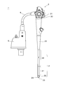
- FIG. 1 is an external view of the endoscope.
- the endoscope 1 includes an intubation tube 2, an operation unit 3, a universal tube 4, and a connector unit 5.
- the insertion tube 2 is a portion to be inserted into the body cavity, and includes a long soft portion 20 and a tip portion 22 connected to one end of the soft portion 20 via a curved portion 21.
- the other end of the flexible portion 20 is connected to the operating portion 3 via a cylindrical connecting portion 23.
- One end of the universal tube 4 is connected to the operation portion 3 and extends in a direction different from that of the insertion tube 2, and the connector portion 5 is continuously provided at the other end of the universal tube 4.
- the operation unit 3 is provided for being gripped by the user to perform various operations, and includes a curved operation knob 30, a plurality of operation buttons 31, and the like.
- the bending operation knob 30 is connected to the bending portion 21 by a wire (not shown) passed through the inside of the connecting portion 23 and the flexible portion 20.
- the curved portion 21 is curved in two directions orthogonal to each other in the axial cross section by the operation of the curved operation knob 30, and the direction of the tip portion 22 inserted into the body cavity is changed.
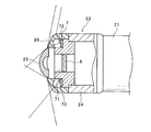
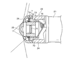
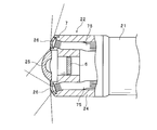
- FIG. 2 is an enlarged view of the tip portion 22 of the insertion tube 2, and is shown by breaking the main portion.
- the tip portion 22 includes a tubular housing 24 whose one side is fixed to the curved portion 21.
- the other side of the housing 24 is covered by a central observation window 25 and an annular light distribution lens 26 surrounding the observation window 25.
- an image pickup unit 6 is incorporated so as to face the inside of the observation window 25, and an illumination unit 7 is incorporated so as to face the inside of the light distribution lens 26.
- the image pickup unit 6 includes an image pickup element such as CMOS (Complementary Metal Oxide Semiconductor) and an optical system for forming an image on the image pickup surface of the image pickup element, and images the inside of the body cavity through the observation window 25.
- the observation window 25 is a wide-angle objective lens, and the imaging unit 6 is configured to enable imaging at a viewing angle of 180 ° or more by setting an optical system including the observation window 25.
- the two-dot chain line in FIG. 2 indicates the imaging field of view of the imaging unit 6.
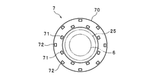
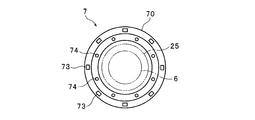
- the illumination unit 7 includes an annular substrate 70 that surrounds the image pickup unit 6 and a first LED 71 and a second LED 72 mounted on one surface of the substrate 70 that faces the light distribution lens 26.
- FIG. 3 is a plan view showing an arrangement example of the first LED 71 and the second LED 72.
- a plurality of the first LED 71 and the second LED 72 (8 in the figure) are provided, respectively, and the first LED 71 is substantially formed on the inner peripheral side (the side closer to the image pickup unit 6) of the annular substrate 70.
- the second LEDs 72 are arranged at intervals, and the second LEDs 72 are arranged at substantially equal intervals outside the parallel area of the first LED 71.
- the positions of the imaging unit 6 and the observation window 25 are indicated by a two-dot chain line.
- the lower half of FIG. 2 shows the cross section at the arrangement position of the first LED 71
- the upper half of FIG. 2 shows the cross section at the arrangement position of the second LED 72.
- the light distribution lens 26 is a tubular lens that extends outward from the peripheral edge of the observation window 25 and has a shape that is continuous with the peripheral wall of the housing 24 through a curved portion, and the light emission of the first LED 71 or the second LED 72 is emitted. , Is emitted through the light distribution lens 26 and illuminates the imaging field of view of the imaging unit 6.
- the broken line in FIG. 2 indicates the light distribution range of the first LED 71 and the second LED 72.
- the light emitted from the first LED 71 located inside is incident on the widened portion of the light distribution lens 26, and is concentrated and distributed in the central portion of the imaging field of view of the imaging unit 6.
- the light emitted from the second LED 72 located on the outside is incident on a wide range from the widened portion to the curved portion of the light distribution lens 26 and spreads widely, and is distributed over the entire image pickup field of view of the image pickup unit 6.
- the inner surface of the light distribution lens 26 is provided with a recess in the vicinity of the curved portion.
- the light distribution of the second LED 72 is irradiated in a wider range than the light distribution of the first LED 71.
- the light irradiation range of the second LED 72 is wider than the light irradiation range of the first LED 71.
- the first LED 71 emits narrow band light including a purple and green wavelength range.
- four of the eight first LEDs 71 which are located every other one, are green LED chips that emit green light, and the remaining four are purple LED chips that emit ultraviolet light.
- the eight first LEDs 71 and the light distribution lens 26 constitute a first light output unit that outputs narrow-band light.
- the second LED 72 is a white LED that emits white light, and is configured by, for example, covering the light emitting surface of a blue LED chip that emits blue light with a yellow phosphor.
- the second LED 72 and the light distribution lens 26 constitute a second light output unit that outputs white light.
- the first and second LEDs 71 and 72 may be other light emitting elements such as LD.
- the imaging by the imaging unit 6 is performed under illumination by narrow band light output from the first light output unit or white light output from the second light output unit.
- the light distribution angle of the white light is larger than the light distribution angle of the narrow band light, preferably substantially equal to the viewing angle of the imaging unit 6, and more preferably equal to or greater than the viewing angle of the imaging unit 6, and a sufficient amount of light is provided in the entire field of view. Imaging underneath is possible.
- the spectrum of narrow-band light is limited, since the light distribution angle of narrow-band light is smaller than the light distribution angle of white light, it is possible to image under the same amount of light as white light within the light distribution range.
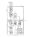
- FIG. 4 is a block diagram of the endoscope device.
- the endoscope 1 is connected to the processor device 10 via the connector portion 5 and is used as an endoscope device.
- the processor device 10 includes a control unit 11, a signal processing circuit 12, an additional processing circuit 13, and the like.
- the control unit 11 includes a CPU, a ROM, and a RAM, and integrally controls the endoscope device by the operation of the CPU according to the control program stored in the ROM.
- the endoscope 1 includes an image pickup drive unit 60 that drives the image pickup unit 6 and an illumination drive unit 76 that drives the illumination unit 7.
- the image pickup drive unit 60 drives the image pickup unit 6 in a rolling shutter manner in accordance with a control command given from the control unit 11.
- the output signal of the image pickup drive unit 60 is given to the gain circuit 62 in units of one frame via the reception circuit 61, performs predetermined preprocessing such as white balance processing, and outputs an image signal to the signal processing circuit 12 of the processor device 10. Will be done.
- the gain value given by the image pickup drive unit 60 is used for the preprocessing of the gain circuit 62.
- the lighting drive unit 76 drives the lighting unit 7 according to a control command given from the control unit 11, and causes the first LED 71 and the second LED 72 to emit light selectively or alternately.
- the image pickup operation of the image pickup unit 6 is executed in synchronization with the drive of the illumination unit 7, and the signal processing circuit 12 is illuminated by the narrow band light by the first LED 71 or the white light by the second LED 72.
- the image output obtained in is continuously or alternately input.
- the operation mode of the lighting unit 7 can be selected by operating the operation button 31 provided on the operation unit 3.
- the signal processing circuit 12 performs image processing such as gamma correction and interpolation processing on the input image and outputs the input image to the additional processing circuit 13.
- the additional processing circuit 13 performs mask processing on the peripheral portion, zoom processing on the image under narrow band light, and further superimposes various characters and images to obtain an image conforming to a predetermined standard. It is converted and output to the external monitor 14. In the image under narrow band light, the area to be masked may be expanded to perform the zoom process.
- the monitor 14 is a display device such as a liquid crystal display or an organic EL display, and displays an image captured by the imaging unit 6 based on an image signal output from the processor device 10. The user of the endoscope 1 can observe a desired portion in the body cavity under the illumination of narrow band light or white light by the display of the monitor 14.
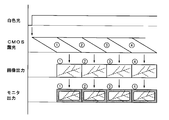
- FIG. 5 to 7 are explanatory views showing the flow of the imaging process
- FIG. 5 is a flow under a single illumination environment with white light
- FIG. 6 is a flow under a single illumination environment with narrow band light
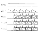
- FIG. 7 shows the flow of alternating illumination by white light and narrow band light in an environment, respectively.
- the image output is given to the processor device 10 in 1-frame units by the CMOS exposure of the imaging unit 6, and the above-described processing is performed. Then, it is output to the monitor 14. Since the white light illuminates an angle range larger than the viewing angle of the imaging unit 6, an image with a sufficient amount of light can be obtained over the entire surface under white light, and this image is masked to obtain a peripheral portion (black). The painted portion) is displayed on the monitor 14 as a masked image.
- the image output under the narrow band light is expanded by zooming the central portion surrounded by the broken line, and further by masking the peripheral portion (the peripheral portion ().
- the black-painted portion) is displayed on the monitor 14 as a masked image.
- the imaging unit 6 has an optical zoom function, the zoom process can be omitted by using this function.
- Narrow-band light is light that includes a purple or green wavelength range, and under narrow-band light, an image in which the capillaries and microstructure patterns on the surface layer of the tissue in the body cavity are emphasized can be obtained.
- the capillaries shown by the broken lines in FIG. 5 are shown by solid lines.
- the narrow-band light is not limited to light including a purple or green wavelength range, and may be a combination of light in another wavelength range and light in a plurality of types of wavelength ranges.
- the user of the endoscope 1 can roughly observe the inside of the body cavity with a wide-angle display image under white light, and switch to a display image under narrow-band light at a desired location such as a lesion in detail. You can make an observation.
- the switching of the display image can be realized by selecting the operation mode of the illumination unit 7 by operating the operation button 31 provided on the operation unit 3 as described above.
- the CMOS exposure time of the imaging unit 6 is extended to 2 frames, and the white light and narrow band light are 1 within the exposure time. Lights up alternately at the frame length.
- image output under white light and image output under narrow band light are alternately obtained, the former is subjected to mask processing, and the latter is sequentially output to the monitor 14 through zoom processing and mask processing. ..
- images under white light and narrow band light are displayed side by side in the order of individual output.
- the user of the endoscope 1 can observe both the captured image under white light and the captured image under narrow band light.
- Alternate illumination of white light and narrow band light can be realized by selecting the operation mode of the illumination unit 7 by operating the operation button 31 provided on the operation unit 3.
- FIG. 8 is an enlarged view of the tip of the insertion tube of the endoscope according to the second embodiment, and corresponds to FIG. 2 in the first embodiment.
- the second embodiment is the same as that of the first embodiment except for the configuration of the lighting unit 7, and the corresponding components are designated by the same reference numerals as those in FIG. 2 and the description thereof will be omitted.
- the illumination unit 7 is incorporated in the housing 24 facing the inside of the light distribution lens 26, and includes an optical fiber bundle 73 and an LED 74 arranged so as to surround the periphery of the image pickup unit 6.
- FIG. 9 is a plan view showing an arrangement example of the optical fiber bundle 73 and the LED 74.
- the imaging unit 6 and the observation window 25 are shown by a two-dot chain line.
- the optical fiber bundles 73 have their respective tips (emission ends) facing the inside of the light distribution lens 26, and are arranged side by side on the concentric circumferences on the outside of the imaging unit 6 at substantially equal intervals.
- the LED 74 is an optical fiber bundle.
- the number of the optical fiber bundles 73 and the LEDs 74 arranged side by side in FIG. 9 is eight, but the number is not limited to this.
- the optical fiber bundle 73 is configured by drawing out a plurality of optical fibers from the tip of the light guide fiber 75, which is formed by bundling a large number of optical fibers.
- the light guide fiber 75 extends to the connector portion 5 through the inside of the insertion tube 2, the operation portion 3, and the universal tube 4, and the end (incident end) of the light guide fiber 75 has a narrow band inside the processor device 10. It faces the light source of light (not shown).
- the light source can be configured by a combination of a filter and a high-intensity lamp that emits white light, such as a xenon lamp or a metal halide lamp. Further, the light source may be a light emitting element such as an LED.
- narrow band light is emitted from the tip of the optical fiber bundle 73, is incident on the widened portion of the light distribution lens 26, and is concentrated and distributed in the central portion of the imaging field of view of the imaging unit 6.
- the light distribution range of the narrow band light of the narrow band light is shown by a broken line.
- the LEDs 74 arranged side by side on the outside of the optical fiber bundle 73 emit white light. This light emission is incident on a wide range from the widened portion to the curved portion of the light distribution lens 26 and spreads widely, and is distributed over the entire image pickup field of view of the image pickup unit 6. In the lower half of FIG. 8, the light distribution range of white light is shown by a broken line.
- the optical fiber bundle 73 and the light distribution lens 26 form a first light output unit that outputs narrow band light
- the LED 74 and the light distribution lens 26 output white light.
- the unit is configured, and imaging under narrow band light and imaging under white light can be performed in the same manner as in the first embodiment. Since the narrow-band light is emitted from the tip of the optical fiber bundle 73 at a small spread angle, the light distribution range of the narrow-band light passing through the light distribution lens 26 is smaller than that of the first embodiment, and is within the light distribution range. A sufficient amount of light can be secured.
- the LED 74 may be another light emitting element such as an LD.
- FIG. 10 is an enlarged view of the tip of the insertion tube of the endoscope according to the third embodiment, and corresponds to FIG. 2 in the first embodiment and FIG. 8 in the second embodiment.
- an observation window 25 is provided in the center on the other side of the housing 24 of the tip portion 22, and two light distribution lenses 26, 26 are provided on the outside of the observation window 25.
- the light distribution lens 26 is a concave lens having an optical axis inclined outward. Inside the housing 24, the image pickup unit 6 faces the inside of the observation window 25, and the image pickup section 6 is incorporated, and the light guide fibers 75 constituting the illumination section 7 have their respective tips (emission ends). It is incorporated so as to face the inside of the light distribution lens 26.
- the light guide fiber 75 is configured by bundling a large number of optical fibers and extends to the connector portion 5 through the inside of the insertion tube 2, the operation portion 3, and the universal tube 4, and is the end (incident end) of the light guide fiber 75. ) Faces the light source unit 8, which will be described later, inside the processor device 10 to which the connector unit 5 is connected.
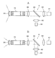
- FIG. 11 is a schematic diagram showing a configuration example of the light source unit 8.
- the light source unit 8 shown in this figure includes a first light source 80 and a second light source 81.
- the second light source 81 is a light source that emits white light, and faces the incident end of the light guide fiber 75 on the same optical axis.
- a collimating lens 83, a half mirror 85, and a condenser lens 84 are arranged in this order on the optical axis between the second light source 81 and the light guide fiber 75.
- the optical path of the white light emitted by the second light source 81 is shown by a two-dot chain line.
- the white light becomes parallel light through the collimated lens 83, passes through the half mirror 85, is condensed by the condenser lens 84, and is incident on the entire incident end of the light guide fiber 75.
- the first light source 80 is a light source that emits narrow-band light, has an optical axis orthogonal to the second light source 81 and the light guide fiber 75, and is arranged so as to face the half mirror 85 via a collimating lens 82. There is. In FIG. 11B, the optical path of the narrow band light emitted by the first light source 80 is shown by a two-dot chain line.
- the half mirror 85 has a reflecting surface having an inclination angle of 45 ° with respect to the optical axis of the first light source 80, and the narrow band light becomes parallel light through the collimated lens 82 and is reflected by the half mirror 85. It reaches the condenser lens 84 and is incident on the central portion of the incident end of the light guide fiber 75.
- the incident light as described above is guided by the light guide fiber 75, reaches the emission end, and is emitted through the light distribution lens 26. Since white light is emitted from the entire surface of the emission end, it is output at a large spread angle through the light distribution lens 26, whereas narrow band light is emitted from the central portion of the emission end, so that it is more than white light. Is also output with a small spread angle.
- the upper half of FIG. 10 shows the light distribution range of white light, and the lower half of FIG. 10 shows the light distribution range of narrow band light with broken lines.
- the first light output unit is composed of the first light source 80, the light guide fiber 75, and the light distribution lens 26, and the second light output is performed by the second light source 81, the light guide fiber 75, and the light distribution lens 26.
- the part is composed. Imaging under narrow band light and imaging under white light can be performed in the same manner as in the first and second embodiments.
- the first light source 80 and the second light source 81 are light emitting elements such as LEDs, or high-intensity lamps such as xenon lamps and metal halide lamps.
- the first light source 80 may be a combination of a plurality of types of light sources that emit light having different wavelengths. In this case, a half mirror 85 corresponding to each light source may be arranged.
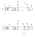
- FIG. 12 is a schematic view showing a configuration example of the light source unit 8 according to the fourth embodiment.
- the light source unit 8 shown in this figure includes a single light source 86.
- the light source 86 faces the incident end of the light guide fiber 75 on the same optical axis and emits white light.
- the collimating lens 83 and the condensing lens 84 are arranged side by side on the optical axis between the light source 88 and the light guide fiber 75.
- the light source unit 8 further includes a condensing filter 87.
- the condensing filter 87 is a combination of a filter and a lens that transmit light of a predetermined wavelength (purple light, green light, etc.), and is arranged so as to be able to be taken in and out on the optical axis between the collimating lens 83 and the condensing lens 84. It is done.
- FIG. 12A shows the optical path when the condensing filter 87 is not arranged by a two-dot chain line.
- the white light emitted by the light source 86 becomes parallel light through the collimated lens 83 and directly reaches the condenser lens 84, and is condensed by the condenser lens 84 at the incident end of the light guide fiber 75. It is incident on the whole.
- FIG. 12B shows the optical path when the condensing filter 87 is arranged by a two-dot chain line.
- the white light emitted by the light source 86 becomes parallel light through the collimating lens 83, becomes narrow band light in which the luminous flux is further narrowed through the condensing filter 87, reaches the condensing lens 84, and reaches the condensing lens 84.
- the light is collected by the light guide fiber 75 and is incident on the central portion of the incident end of the light guide fiber 75.
- the incident light is guided by the light guide fiber 75, reaches the emission end, and is emitted via the light distribution lens 26. Since white light is emitted from the entire surface of the emission end, it is output at a large spread angle through the light distribution lens 26, whereas narrow band light is emitted from the central portion of the emission end, so that it is more than white light. Is also output with a small spread angle.
- the first light output unit is composed of the light source 86, the condensing filter 87, the light guide fiber 75 and the light distribution lens 26, and the second light is formed by the light source 86, the light guide fiber 75 and the light distribution lens 26.
- the output unit is configured, and imaging under narrow band light and imaging under white light can be performed in the same manner as in the third embodiment.
- the light source 86 may be a high-intensity lamp such as a xenon lamp or a metal halide lamp, or may be a light emitting element such as a white LED.
- the light collecting filter 87 can be taken in and out by an appropriate actuator.
Landscapes
- Health & Medical Sciences (AREA)
- Life Sciences & Earth Sciences (AREA)
- Surgery (AREA)
- Physics & Mathematics (AREA)
- Optics & Photonics (AREA)
- Engineering & Computer Science (AREA)
- Medical Informatics (AREA)
- General Health & Medical Sciences (AREA)
- Pathology (AREA)
- Nuclear Medicine, Radiotherapy & Molecular Imaging (AREA)
- Biomedical Technology (AREA)
- Heart & Thoracic Surgery (AREA)
- Biophysics (AREA)
- Molecular Biology (AREA)
- Animal Behavior & Ethology (AREA)
- Radiology & Medical Imaging (AREA)
- Public Health (AREA)
- Veterinary Medicine (AREA)
- Microelectronics & Electronic Packaging (AREA)
- Astronomy & Astrophysics (AREA)
- General Physics & Mathematics (AREA)
- Endoscopes (AREA)
- Instruments For Viewing The Inside Of Hollow Bodies (AREA)
- Signal Processing (AREA)
Abstract
内視鏡は、挿入管の先端部に組み込んであり、観察窓を通して観察箇所を撮像する撮像部と、撮像部の外側に並設された複数の第1のLEDと、第1のLEDの並設域の外側に並設された複数の第2のLEDとを備える。第1のLED及び第2のLEDの並設域は、配光レンズで覆ってあり、第1のLEDの発光は、配光レンズを経て撮像部の視野角よりも小さい角度範囲に出力され、第2のLEDの発光は配光レンズを経て撮像部の視野角よりも小さい角度範囲に出力される。
Description
本発明は、内視鏡及び内視鏡装置に関する。
内視鏡は、被検者の体腔内に挿入することで所望の箇所の観察、処置を可能とする医療用機器であり、体腔内に挿入される挿入管の先端部に組み込まれた撮像部と、該撮像部の撮像視野を照明する照明装置とを備えている。特許文献1には、180°以上の広い角度範囲での照明を実現する照明装置を備え、広視野角での観察を可能とした内視鏡が開示されている。
また近年においては、白色光下での観察に加えて、狭帯域光(紫色光、緑色光等)による照明下で得られる画像強調観察を可能とした内視鏡も普及しており、特許文献2には、白色光及び狭帯域光を交互に照射して画像を取得する内視鏡装置が開示されている。
特許文献2に開示された白色光及び狭帯域光による照明下での観察は、特許文献1に開示された広視野角の内視鏡においても可能である。しかしながら、狭帯域光のスペクトルは限定されており、白色光と同一条件下では視野全体への必要光量の確保が難しい。
本開示の目的は、白色光及び狭帯域光の照明下での広視野角の観察を良好に行わせ得る内視鏡及び内視鏡装置を提供することである。
本開示に係る内視鏡は、挿入管の先端部に組み込まれ、観察窓を通して観察箇所を撮像する撮像部と、前記観察窓の周囲に配設され、前記観察箇所を照明する第1の照明光を出力する第1光出力部と、前記観察窓の周囲に配設され、前記観察箇所を照明する第2の照明光を前記第1光出力部よりも大きい角度範囲に出力する第2光出力部とを備える。
また、前記撮像部の外側に並設された複数の第1の発光素子と、前記第1の発光素子の並設域の外側に並設された複数の第2の発光素子と、前記観察窓の周囲に配設され、前記第1の発光素子及び第2の発光素子の並設域を覆う配光レンズとを備え、前記第1光出力部は、前記第1の発光素子及び配光レンズを含み、前記第2光出力部は、前記第2の発光素子及び配光レンズを含む。
また、前記撮像部の外側に並設された複数の出射端を有するライトガイドファイバと、該ライトガイドファイバの入射端に光を入射する光源と、前記出射端の並設域の外側に並設された複数の発光素子と、前記観察窓の周囲に配設され、前記出射端及び発光素子の並設域を覆う配光レンズとを備え、前記第1光出力部は、前記ライトガイドファイバ、光源及び配光レンズを含み、前記第2光出力部は、前記発光素子及び配光レンズを含む。
また、前記撮像部の外側に出射端を有するライトガイドファイバと、該ライトガイドファイバの入射端に臨ませてあり、該入射端の中心部に光を入射する第1光源と、前記ライトガイドファイバの入射端に臨ませてあり、該入射端の全体に光を入射する第2光源と、前記ライトガイドファイバの出射端を覆う配光レンズとを備え、前記第1光出力部は、前記ライトガイドファイバ、第1光源及び配光レンズを含み、前記第2光出力部は、前記ライトガイドファイバ、第2光源及び配光レンズを含む。
また、前記第2光出力部による第2の照明光の角度範囲は、前記撮像部の視野角以上である。
また、前記撮像部は、180°以上の視野角を有する。
また、前記第1の照明光は、狭帯域光であり、前記第2の照明光は、白色光である。
本開示に係る内視鏡装置は、挿入管の先端部に組み込まれ、観察窓を通して観察箇所を撮像する撮像部、前記観察窓の周囲に配設され、前記観察箇所を照明する第1の照明光を出力する第1光出力部、及び前記観察窓の周囲に配設され、前記観察箇所を照明する第2の照明光を前記第1光出力部よりも大きい角度範囲に出力する第2光出力部を備える内視鏡と、前記第1光出力部又は第2光出力部による照明下での前記撮像部の撮像画像を周縁部をマスク処理して出力する画像処理部とを備える。
また、前記第1光出力部による照明下での撮像画像又は第2光出力部による照明下での撮像画像を交互に取得し、並べて表示させる。
本開示によれば、白色光及び狭帯域光の照明下での広視野角の観察が可能となる。
以下、本開示の実施の形態を図面に基づき説明する。
(実施の形態1)
図1は、内視鏡の外観図である。図示の如く内視鏡1は、挿入管2、操作部3、ユニバーサルチューブ4及びコネクタ部5を備えている。挿入管2は、体腔内に挿入される部分であり、長尺の軟性部20と、該軟性部20の一端に湾曲部21を介して連結された先端部22とを備える。軟性部20の他端は、円筒形の連結部23を介して操作部3に連結されている。ユニバーサルチューブ4は、操作部3に一端を連結され挿入管2と異なる向きに延びており、コネクタ部5は、ユニバーサルチューブ4の他端に連設されている。
(実施の形態1)
図1は、内視鏡の外観図である。図示の如く内視鏡1は、挿入管2、操作部3、ユニバーサルチューブ4及びコネクタ部5を備えている。挿入管2は、体腔内に挿入される部分であり、長尺の軟性部20と、該軟性部20の一端に湾曲部21を介して連結された先端部22とを備える。軟性部20の他端は、円筒形の連結部23を介して操作部3に連結されている。ユニバーサルチューブ4は、操作部3に一端を連結され挿入管2と異なる向きに延びており、コネクタ部5は、ユニバーサルチューブ4の他端に連設されている。
操作部3は、使用者により把持されて各種の操作を行うために設けてあり、湾曲操作ノブ30、複数の操作ボタン31等を備えている。湾曲操作ノブ30は、連結部23及び軟性部20の内部に通したワイヤ(図示せず)により湾曲部21に連結されている。湾曲部21は、湾曲操作ノブ30の操作により軸断面内で互いに直交する2方向に湾曲し、体腔内に挿入された先端部22の向きが変化する。
図2は、挿入管2の先端部22の拡大図であり、要部を破断して示してある。先端部22は、湾曲部21に一側を固定された筒形のハウジング24を備えている。ハウジング24の他側は、中央の観察窓25と、該観察窓25の周囲を囲う環状の配光レンズ26とによって覆われている。ハウジング24の内部には、観察窓25の内側に面して撮像部6が組み込まれ、配光レンズ26の内側に面して照明部7が組み込まれている。
撮像部6は、CMOS(Complementary Metal Oxide Semiconductor )等の撮像素子と、該撮像素子の撮像面上に結像させるための光学系とを備え、観察窓25を通して体腔内を撮像する。観察窓25は、広角の対物レンズであり、撮像部6は、観察窓25を含む光学系の設定により、180°以上の視野角での撮像が可能となるように構成されている。図2中の2点鎖線は、撮像部6の撮像視野を示している。
照明部7は、撮像部6の周囲を囲う環状の基板70と、配光レンズ26に対向する基板70の一面上に実装された第1のLED71及び第2のLED72とを備える。図3は、第1のLED71及び第2のLED72の配置例を示す平面図である。第1のLED71及び第2のLED72は、夫々複数(図においては8個)設けてあり、第1のLED71は、環状をなす基板70の内周側(撮像部6に近い側)に略等間隔で配置され、第2のLED72は、第1のLED71の並設域の外側に略等間隔で配置されている。図3中には、撮像部6及び観察窓25の位置が2点鎖線により示してある。
図2の下半部は、第1のLED71の配設位置における断面を示し、図2の上半部は、第2のLED72の配設位置における断面を示している。配光レンズ26は、観察窓25の周縁部から外向きに広がり、湾曲部分を経てハウジング24の周壁に連続する形状を有する筒状レンズであり、第1のLED71又は第2のLED72の発光は、配光レンズ26を通して出射され、撮像部6の撮像視野を照明する。
図2中の破線は、第1のLED71及び第2のLED72の配光範囲を示している。内側に位置する第1のLED71の発光は、配光レンズ26の広がり部分に入射し、撮像部6の撮像視野の中央部分に集中して配光される。一方、外側に位置する第2のLED72の発光は、配光レンズ26の広がり部分から湾曲部分までの広範囲に入射して大きく広がり、撮像部6の撮像視野の全域に配光される。なお、配光レンズ26の内面には、湾曲部分の近傍に凹部が設けられている。この凹部の作用により、第2のLED72の配光は、第1のLED71の配光に比べて広範囲に照射されるようになる。換言すれば、第2のLED72による光の照射範囲は、第1のLED71による光の照射範囲に比べて広くなっている。
第1のLED71は、紫色、緑色の波長域を含む狭帯域光を発光する。例えば、8個の第1のLED71のうち一つ置きに位置する4個は、緑色光を発光する緑色LEDチップであり、残りの4個は、紫外光を発光する紫色LEDチップであって、これら8個の第1のLED71と配光レンズ26とにより狭帯域光を出力する第1光出力部が構成されている。
第2のLED72は、白色の光を発光する白色LEDであり、例えば、青色光を発光する青色LEDチップの発光面を黄色蛍光体により覆って構成される。このような第2のLED72と配光レンズ26とにより白色光を出力する第2光出力部が構成されている。なお第1、第2のLED71、72は、LD等の他の発光素子であってもよい。
撮像部6による撮像は、第1光出力部から出力される狭帯域光、又は第2光出力部から出力される白色光による照明下にて実施される。白色光の配光角度は、狭帯域光の配光角度よりも大きく、望ましくは撮像部6の視野角とほぼ等しく、より望ましくは撮像部6の視野角以上としてあり、視野全体で十分な光量下での撮像が可能である。狭帯域光のスペクトルは限定されるが、狭帯域光の配光角度は白色光の配光角度よりも小さいから、配光範囲内では白色光と同等の光量下での撮像が可能である。
図4は、内視鏡装置のブロック図である。内視鏡1は、コネクタ部5を介してプロセッサ装置10に接続し内視鏡装置として用いられる。プロセッサ装置10は、制御部11、信号処理回路12、付加処理回路13等を備えている。制御部11は、CPU、ROM、RAMを備え、ROMに記憶された制御プログラムに従うCPUの動作により内視鏡装置を統合制御する。
内視鏡1は、撮像部6を駆動する撮像駆動部60及び照明部7を駆動する照明駆動部76を備えている。撮像駆動部60は、制御部11から与えられる制御指令に従ってローリングシャッタ方式で撮像部6を駆動する。撮像駆動部60の出力信号は、受信回路61を経て1フレーム単位でゲイン回路62に与えられ、ホワイトバランス処理等の所定の前処理を行ってプロセッサ装置10の信号処理回路12に画像信号が出力される。ゲイン回路62の前処理には、撮像駆動部60から与えられるゲイン値が用いられる。
照明駆動部76は、制御部11から与えられる制御指令に従って照明部7を駆動し、第1のLED71及び第2のLED72を選択的に、又は交互に発光させる。撮像部6の撮像動作は、照明部7の駆動に同期して実行され、信号処理回路12には、第1のLED71による狭帯域光の照明下、又は第2のLED72による白色光の照射下で得られる画像出力が連続的に、又は交互に入力される。照明部7の動作態様は、操作部3に設けられた操作ボタン31の操作により選択することができる。
信号処理回路12は、入力画像に対し、ガンマ補正、補間処理等の画像処理を行って付加処理回路13に出力する。付加処理回路13は、周縁部のマスク処理を行い、また狭帯域光下での画像に対してはズーム処理を行い、更に、各種文字及び画像の重畳処理等により所定の規格に準拠した画像に変換して外部のモニタ14に出力する。なお、狭帯域光下での画像は、ズーム処理を行わすにマスク処理する領域を広げてもよい。モニタ14は、液晶ディスプレイ、有機ELディスプレイ等の表示機器であり、プロセッサ装置10から出力される画像信号に基づいて撮像部6による撮像画像を表示する。内視鏡1の使用者は、モニタ14の表示により体腔内の所望箇所を狭帯域光又は白色光の照明下で観察することができる。
図5~図7は、撮像処理の流れを示す説明図であり、図5は、白色光による単独照明の環境下での流れを、図6は狭帯域光による単独照明の環境下での流れを、図7は、白色光と狭帯域光とによる交互照明の環境下での流れを夫々示している。
図5及び図6に示すように、白色光又は狭帯域光の単独照明下においては、撮像部6のCMOSの露光により、1フレーム単位で画像出力がプロセッサ装置10に与えられ、前述した処理を経てモニタ14に出力される。白色光は、撮像部6の視野角よりも大きい角度範囲を照明するから、白色光下では、全面に亘って十分な光量での画像が得られ、この画像は、マスク処理により周縁部(黒塗り部分)がマスクされた画像としてモニタ14に表示される。
一方、狭帯域光の照明範囲は、撮像部6の視野角よりも小さいから、狭帯域光下の画像出力は、破線で囲った中央部分をズーム処理により拡大し、更にマスク処理により周縁部(黒塗り部分)がマスクされた画像としてモニタ14に表示される。なお、撮像部6が光学的なズーム機能を有している場合には、この機能を利用することでズーム処理を省略することができる。
狭帯域光は、紫色又は緑色の波長域を含む光であり、狭帯域光下では、体腔内の組織表層の毛細血管及び微細構造模様が強調された画像が得られる。図6においては、図5において破線で示した毛細血管を実線で示してある。狭帯域光は、紫色又は緑色の波長域を含む光に限らず、他の波長域の光、更には、複数種の波長域の光の組み合わせであってもよい。
内視鏡1の使用者は、例えば、白色光下での広角の表示画像により体腔内を大まかに観察し、病変部等の所望箇所で狭帯域光下での表示画像に切り換えることにより詳細な観察を行わせることができる。表示画像の切り換えは、前述の如く、操作部3に設けられた操作ボタン31の操作により照明部7の動作態様を選択することで実現し得る。
白色光と狭帯域光とによる交互照明の環境下においては、図7に示すように、撮像部6のCMOSの露光時間を2フレーム分に延ばし、白色光及び狭帯域光を露光時間内の1フレーム長で交互に発光させる。これにより、白色光下での画像出力及び狭帯域光下での画像出力が交互に得られ、前者は、マスク処理を経て、後者は、ズーム処理及びマスク処理を経てモニタ14に順次出力される。モニタ14においては、白色光下及び狭帯域光下での画像が個々の出力順に並べて表示される。
内視鏡1の使用者は、白色光下での撮像画像と狭帯域光下での撮像画像を併せて観察することができる。白色光及び狭帯域光の交互照明は、操作部3に設けられた操作ボタン31の操作により照明部7の動作態様を選択することで実現し得る。
(実施の形態2)
図8は、実施の形態2に係る内視鏡の挿入管の先端部の拡大図であり、実施の形態1における図2に相当する。実施の形態2は、照明部7の構成以外は実施の形態1と同様であり、対応する構成要素に図2と同一の参照符号を付して説明を省略する。
図8は、実施の形態2に係る内視鏡の挿入管の先端部の拡大図であり、実施の形態1における図2に相当する。実施の形態2は、照明部7の構成以外は実施の形態1と同様であり、対応する構成要素に図2と同一の参照符号を付して説明を省略する。
照明部7は、配光レンズ26の内側に面してハウジング24内に組み込まれており、撮像部6の周囲を囲うように配設された光ファイバ束73とLED74とを備える。図9は、光ファイバ束73及びLED74の配置例を示す平面図である。図9中には、撮像部6及び観察窓25が2点鎖線により示してある。光ファイバ束73は、夫々の先端(出射端)を配光レンズ26の内側に臨ませ、撮像部6の外側の同心円周上に略等間隔で並べて配置してある、LED74は、光ファイバ束73の並設域の外側に配した環状の基板70上に実装され、略等間隔で並べて配置されている。図9中の光ファイバ束73及びLED74の並設数は夫々8つとしてあるが、これに限るものではない。
光ファイバ束73は、多数本の光ファイバを束ねて構成されたライトガイドファイバ75の先端から複数本単位で引き出して構成されている。ライトガイドファイバ75は、挿入管2、操作部3及びユニバーサルチューブ4の内部を通してコネクタ部5に延設されており、ライトガイドファイバ75の末端(入射端)は、プロセッサ装置10の内部において狭帯域光の光源(図示せず)に臨ませてある。光源は、例えば、キセノンランプ、メタルハライドランプ等の白色光を発光する高輝度ランプとフィルタとの組み合わせにより構成することができる。また光源は、LED等の発光素子であってもよい。
以上の構成により光ファイバ束73の先端からは、狭帯域光が出射され、配光レンズ26の広がり部分に入射して撮像部6の撮像視野の中央部分に集中して配光される。図8の下半部には、狭帯域光の狭帯域光の配光範囲が破線で示されている。
光ファイバ束73の外側に並設されたLED74は、白色光を発光する。この発光は、配光レンズ26の広がり部分から湾曲部分までの広範囲に入射して大きく広がり、撮像部6の撮像視野の全域に配光される。図8の下半部には、白色光の配光範囲が破線で示されている。
実施の形態2においては、光ファイバ束73と配光レンズ26とにより狭帯域光を出力する第1光出力部が構成され、LED74と配光レンズ26とにより白色光を出力する第2光出力部が構成されており、狭帯域光下での撮像と白色光下での撮像とを実施の形態1と同様に実施することができる。狭帯域光は、光ファイバ束73の先端から小さい広がり角で出射されるから、配光レンズ26を通した狭帯域光の配光範囲は実施の形態1よりも小さくなり、配光範囲内で十分な光量を確保することができる。なおLED74は、LD等の他の発光素子であってもよい。
(実施の形態3)
図10は、実施の形態3に係る内視鏡の挿入管の先端部の拡大図であり、実施の形態1における図2及び実施の形態2における図8に相当する。
図10は、実施の形態3に係る内視鏡の挿入管の先端部の拡大図であり、実施の形態1における図2及び実施の形態2における図8に相当する。
実施の形態3において、先端部22のハウジング24の他側には、中央に観察窓25が設けられ、この観察窓25の外側に2つの配光レンズ26、26が設けられている。配光レンズ26は、外向きに傾斜した光軸を有する凹レンズである。ハウジング24の内部には、撮像部6が、観察窓25の内側に面して撮像部6が組み込まれ、照明部7を構成するライトガイドファイバ75が、夫々の先端(出射端)を夫々の配光レンズ26の内側に臨ませて組み込まれている。
ライトガイドファイバ75は、多数本の光ファイバを束ねて構成され、挿入管2、操作部3及びユニバーサルチューブ4の内部を通してコネクタ部5に延設されており、ライトガイドファイバ75の末端(入射端)は、コネクタ部5が接続されるプロセッサ装置10の内部において後述する光源部8に臨ませてある。
図11は、光源部8の構成例を示す模式図である。本図に示す光源部8は、第1光源80及び第2光源81を備える。第2光源81は、白色光を発光する光源であり、ライトガイドファイバ75の入射端に同一の光軸上で正対させてある。第2光源81とライトガイドファイバ75との間の光軸上には、コリメートレンズ83、ハーフミラー85及び集光レンズ84が、この順に並べて配してある。図11Aには、第2光源81が発光する白色光の光路を2点鎖線により示してある。白色光は、コリメートレンズ83を通して平行光となり、ハーフミラー85を透過して集光レンズ84により集光され、ライトガイドファイバ75の入射端の全体に入射される。
第1光源80は、狭帯域光を発光する光源であり、第2光源81とライトガイドファイバ75と直交する光軸を有し、コリメートレンズ82を介してハーフミラー85に対向して配置されている。図11Bには、第1光源80が発光する狭帯域光の光路を2点鎖線により示してある。ハーフミラー85は、第1光源80の光軸に対して45°の傾斜角を有する反射面を有しており、狭帯域光は、コリメートレンズ82を通して平行光となり、ハーフミラー85により反射されて集光レンズ84に達し、ライトガイドファイバ75の入射端の中央部に入射される。
以上の如き入射光は、ライトガイドファイバ75に導光されて出射端に達し、配光レンズ26を経て出射される。白色光は、出射端の全面から出射されるから、配光レンズ26を経て大きい広がり角で出力されるのに対し、狭帯域光は、出射端の中央部から出射されるから、白色光よりも小さい広がり角で出力される。図10の上半部には、白色光の配光範囲が、図10の下半部には、狭帯域光の配光範囲が夫々破線で示されている。
実施の形態3においては、第1光源80、ライトガイドファイバ75及び配光レンズ26により第1光出力部が構成され、第2光源81、ライトガイドファイバ75及び配光レンズ26により第2光出力部が構成されており。狭帯域光下での撮像と白色光下での撮像とを実施の形態1、2と同様に実施することができる。第1光源80、第2光源81は、LED等の発光素子、又は、キセノンランプ、メタルハライドランプ等の高輝度ランプである。第1光源80は、異なる波長の光を発光する複数種の光源の組み合わせであってもよく、この場合、夫々の光源に対応するハーフミラー85を配置すればよい。
(実施の形態4)
実施の形態4は、実施の形態3と光源部8の構成が相違する。図12は、実施の形態4に係る光源部8の構成例を示す模式図である。本図に示す光源部8は、単一の光源86を備える。光源86は、ライトガイドファイバ75の入射端に同一の光軸上で正対させてあり、白色光を発光する。光源88とライトガイドファイバ75との間の光軸上には、実施の形態3と同様、コリメートレンズ83及び集光レンズ84が、この順に並べて配してある。
実施の形態4は、実施の形態3と光源部8の構成が相違する。図12は、実施の形態4に係る光源部8の構成例を示す模式図である。本図に示す光源部8は、単一の光源86を備える。光源86は、ライトガイドファイバ75の入射端に同一の光軸上で正対させてあり、白色光を発光する。光源88とライトガイドファイバ75との間の光軸上には、実施の形態3と同様、コリメートレンズ83及び集光レンズ84が、この順に並べて配してある。
光源部8は、更に、集光フィルタ87を備えている。集光フィルタ87は、所定波長の光(紫色光、緑色光等)を透過させるフィルタとレンズとの組み合わせであり、コリメートレンズ83と集光レンズ84との間の光軸上に出し入れ可能に配置してある。
図12Aには、集光フィルタ87が配置されていない場合の光路を2点鎖線により示してある。この場合、光源86が発光する白色光は、コリメートレンズ83を通して平行光となって集光レンズ84に直接的に到達し、該集光レンズ84により集光されてライトガイドファイバ75の入射端の全体に入射される。
図12Bには、集光フィルタ87が配置されている場合の光路を2点鎖線により示してある。この場合、光源86が発光する白色光は、コリメートレンズ83を通して平行光となり、更に集光フィルタ87を通して光束が絞られた狭帯域光となって集光レンズ84に到達し、該集光レンズ84により集光されてライトガイドファイバ75の入射端の中央部に入射される。
この入射光は、実施の形態3と同様、ライトガイドファイバ75により導光されて出射端に達し、配光レンズ26を経て出射される。白色光は、出射端の全面から出射されるから、配光レンズ26を経て大きい広がり角で出力されるのに対し、狭帯域光は、出射端の中央部から出射されるから、白色光よりも小さい広がり角で出力される。
実施の形態4においては、光源86、集光フィルタ87、ライトガイドファイバ75及び配光レンズ26により第1光出力部が構成され、光源86、ライトガイドファイバ75及び配光レンズ26により第2光出力部が構成されており、狭帯域光下での撮像と白色光下での撮像とを実施の形態3と同様に実施することができる。光源86は、キセノンランプ、メタルハライドランプ等の高輝度ランプであってもよく、白色LED等の発光素子であってもよい。集光フィルタ87の出し入れは、適宜のアクチュエータにより実現することができる。
なお、今回開示された実施の形態は、すべての点で例示であって制限的なものではないと考えられるべきである。本発明の範囲は、上記した意味ではなく、請求の範囲によって示され、請求の範囲と均等な意味および範囲内でのすべての変更が含まれることが意図される。
1 内視鏡
2 挿入管
6 撮像部
7 照明部
8 光源部
22 先端部
25 観察窓
26 配光レンズ
71 第1のLED(第1の発光素子)
72 第2のLED(第2の発光素子)
73 光ファイバ束
74 LED(発光素子)
75 ライトガイドファイバ
80 第1光源
81 第2光源
2 挿入管
6 撮像部
7 照明部
8 光源部
22 先端部
25 観察窓
26 配光レンズ
71 第1のLED(第1の発光素子)
72 第2のLED(第2の発光素子)
73 光ファイバ束
74 LED(発光素子)
75 ライトガイドファイバ
80 第1光源
81 第2光源
Claims (9)
- 挿入管の先端部に組み込まれ、観察窓を通して観察箇所を撮像する撮像部と、
前記観察窓の周囲に配設され、前記観察箇所を照明する第1の照明光を出力する第1光出力部と、
前記観察窓の周囲に配設され、前記観察箇所を照明する第2の照明光を前記第1光出力部よりも大きい角度範囲に出力する第2光出力部とを備える内視鏡。 - 前記撮像部の外側に並設された複数の第1の発光素子と、
前記第1の発光素子の並設域の外側に並設された複数の第2の発光素子と、
前記観察窓の周囲に配設され、前記第1の発光素子及び第2の発光素子の並設域を覆う配光レンズとを備え、
前記第1光出力部は、前記第1の発光素子及び配光レンズを含み、前記第2光出力部は
、前記第2の発光素子及び配光レンズを含む請求項1に記載の内視鏡。 - 前記撮像部の外側に並設された複数の出射端を有するライトガイドファイバと、
該ライトガイドファイバの入射端に光を入射する光源と、
前記出射端の並設域の外側に並設された複数の発光素子と、
前記観察窓の周囲に配設され、前記出射端及び発光素子の並設域を覆う配光レンズとを備え、
前記第1光出力部は、前記ライトガイドファイバ、光源及び配光レンズを含み、前記第2光出力部は、前記発光素子及び配光レンズを含む請求項1に記載の内視鏡。 - 前記撮像部の外側に出射端を有するライトガイドファイバと、
該ライトガイドファイバの入射端に臨ませてあり、該入射端の中心部に光を入射する第1光源と、
前記ライトガイドファイバの入射端に臨ませてあり、該入射端の全体に光を入射する第2光源と、
前記ライトガイドファイバの出射端を覆う配光レンズとを備え、
前記第1光出力部は、前記ライトガイドファイバ、第1光源及び配光レンズを含み、前記第2光出力部は、前記ライトガイドファイバ、第2光源及び配光レンズを含む請求項1に記載の内視鏡。 - 前記第2光出力部による第2の照明光の角度範囲は、前記撮像部の視野角以上である請求項1から請求項4のいずれか1つに記載の内視鏡。
- 前記撮像部は、180°以上の視野角を有する請求項1から請求項5のいずれか1つに記載の内視鏡。
- 前記第1の照明光は、狭帯域光であり、前記第2の照明光は、白色光である請求項1から請求項6のいずれか1つに記載の内視鏡。
- 挿入管の先端部に組み込まれ、観察窓を通して観察箇所を撮像する撮像部、前記観察窓の周囲に配設され、前記観察箇所を照明する第1の照明光を出力する第1光出力部、及び前記観察窓の周囲に配設され、前記観察箇所を照明する第2の照明光を前記第1光出力部よりも大きい角度範囲に出力する第2光出力部を含む内視鏡と、
前記第1光出力部又は第2光出力部による照明下での前記撮像部の撮像画像を周縁部をマスク処理して出力する画像処理部とを備える内視鏡装置。 - 前記第1光出力部による照明下での撮像画像又は第2光出力部による照明下での撮像画像を交互に取得し、並べて表示させる請求項8に記載の内視鏡装置。
Priority Applications (3)
| Application Number | Priority Date | Filing Date | Title |
|---|---|---|---|
| CN202080032595.2A CN113766867B (zh) | 2019-10-08 | 2020-09-25 | 内窥镜及内窥镜装置 |
| DE112020004901.9T DE112020004901T5 (de) | 2019-10-08 | 2020-09-25 | Endoskop und endoskopvorrichtung |
| US17/615,728 US20220240768A1 (en) | 2019-10-08 | 2020-09-25 | Endoscope and endoscopic device |
Applications Claiming Priority (2)
| Application Number | Priority Date | Filing Date | Title |
|---|---|---|---|
| JP2019185359A JP7229142B2 (ja) | 2019-10-08 | 2019-10-08 | 内視鏡及び内視鏡装置 |
| JP2019-185359 | 2019-10-08 |
Publications (1)
| Publication Number | Publication Date |
|---|---|
| WO2021070634A1 true WO2021070634A1 (ja) | 2021-04-15 |
Family
ID=75380822
Family Applications (1)
| Application Number | Title | Priority Date | Filing Date |
|---|---|---|---|
| PCT/JP2020/036292 WO2021070634A1 (ja) | 2019-10-08 | 2020-09-25 | 内視鏡及び内視鏡装置 |
Country Status (5)
| Country | Link |
|---|---|
| US (1) | US20220240768A1 (ja) |
| JP (1) | JP7229142B2 (ja) |
| CN (1) | CN113766867B (ja) |
| DE (1) | DE112020004901T5 (ja) |
| WO (1) | WO2021070634A1 (ja) |
Families Citing this family (1)
| Publication number | Priority date | Publication date | Assignee | Title |
|---|---|---|---|---|
| US20210153725A1 (en) * | 2019-11-22 | 2021-05-27 | Lake Region Manufacturing, Inc. | Guidewire And Catheter System For In-Vivo Forward Viewing Of The Vasculature |
Citations (11)
| Publication number | Priority date | Publication date | Assignee | Title |
|---|---|---|---|---|
| JPH05297288A (ja) * | 1992-04-16 | 1993-11-12 | Olympus Optical Co Ltd | 内視鏡及び内視鏡装置 |
| JP2001258823A (ja) * | 2000-03-14 | 2001-09-25 | Olympus Optical Co Ltd | 内視鏡 |
| JP2004321244A (ja) * | 2003-04-21 | 2004-11-18 | Olympus Corp | 電子内視鏡システム |
| JP2005073708A (ja) * | 2003-08-29 | 2005-03-24 | Pentax Corp | 電子内視鏡 |
| JP2006034543A (ja) * | 2004-07-26 | 2006-02-09 | Olympus Corp | 内視鏡、及びその修理方法 |
| JP2009219573A (ja) * | 2008-03-14 | 2009-10-01 | Fujinon Corp | 内視鏡用画像処理装置及び内視鏡用画像処理方法 |
| JP2011024901A (ja) * | 2009-07-28 | 2011-02-10 | Hoya Corp | 電子内視鏡システムおよび調光信号補正方法 |
| JP2012075562A (ja) * | 2010-09-30 | 2012-04-19 | Fujifilm Corp | 内視鏡用光源装置 |
| JP2016202441A (ja) * | 2015-04-20 | 2016-12-08 | 富士フイルム株式会社 | 内視鏡用光源装置、およびこれを用いた内視鏡システム |
| WO2016203626A1 (ja) * | 2015-06-18 | 2016-12-22 | オリンパス株式会社 | 内視鏡システムおよび照明装置 |
| JP2019130049A (ja) * | 2018-01-31 | 2019-08-08 | Hoya株式会社 | 電子内視鏡システム、プロセッサ及び制御方法 |
Family Cites Families (3)
| Publication number | Priority date | Publication date | Assignee | Title |
|---|---|---|---|---|
| JP5297288B2 (ja) * | 2009-07-17 | 2013-09-25 | 三菱重工業株式会社 | 衝撃吸収構造体 |
| JP6190906B2 (ja) | 2013-01-10 | 2017-08-30 | 富士フイルム株式会社 | 撮像モジュール、及び内視鏡装置 |
| JP6192398B2 (ja) | 2013-07-09 | 2017-09-06 | オリンパス株式会社 | 照明装置 |
-
2019
- 2019-10-08 JP JP2019185359A patent/JP7229142B2/ja active Active
-
2020
- 2020-09-25 DE DE112020004901.9T patent/DE112020004901T5/de active Pending
- 2020-09-25 US US17/615,728 patent/US20220240768A1/en active Pending
- 2020-09-25 WO PCT/JP2020/036292 patent/WO2021070634A1/ja active Application Filing
- 2020-09-25 CN CN202080032595.2A patent/CN113766867B/zh active Active
Patent Citations (11)
| Publication number | Priority date | Publication date | Assignee | Title |
|---|---|---|---|---|
| JPH05297288A (ja) * | 1992-04-16 | 1993-11-12 | Olympus Optical Co Ltd | 内視鏡及び内視鏡装置 |
| JP2001258823A (ja) * | 2000-03-14 | 2001-09-25 | Olympus Optical Co Ltd | 内視鏡 |
| JP2004321244A (ja) * | 2003-04-21 | 2004-11-18 | Olympus Corp | 電子内視鏡システム |
| JP2005073708A (ja) * | 2003-08-29 | 2005-03-24 | Pentax Corp | 電子内視鏡 |
| JP2006034543A (ja) * | 2004-07-26 | 2006-02-09 | Olympus Corp | 内視鏡、及びその修理方法 |
| JP2009219573A (ja) * | 2008-03-14 | 2009-10-01 | Fujinon Corp | 内視鏡用画像処理装置及び内視鏡用画像処理方法 |
| JP2011024901A (ja) * | 2009-07-28 | 2011-02-10 | Hoya Corp | 電子内視鏡システムおよび調光信号補正方法 |
| JP2012075562A (ja) * | 2010-09-30 | 2012-04-19 | Fujifilm Corp | 内視鏡用光源装置 |
| JP2016202441A (ja) * | 2015-04-20 | 2016-12-08 | 富士フイルム株式会社 | 内視鏡用光源装置、およびこれを用いた内視鏡システム |
| WO2016203626A1 (ja) * | 2015-06-18 | 2016-12-22 | オリンパス株式会社 | 内視鏡システムおよび照明装置 |
| JP2019130049A (ja) * | 2018-01-31 | 2019-08-08 | Hoya株式会社 | 電子内視鏡システム、プロセッサ及び制御方法 |
Also Published As
| Publication number | Publication date |
|---|---|
| CN113766867B (zh) | 2024-03-19 |
| JP7229142B2 (ja) | 2023-02-27 |
| CN113766867A (zh) | 2021-12-07 |
| DE112020004901T5 (de) | 2022-06-23 |
| JP2021058468A (ja) | 2021-04-15 |
| US20220240768A1 (en) | 2022-08-04 |
Similar Documents
| Publication | Publication Date | Title |
|---|---|---|
| JP2008514304A (ja) | 内視鏡検査用の固体照明 | |
| JP2001008892A (ja) | 光源装置及び内視鏡システム | |
| JP6140100B2 (ja) | 内視鏡装置及び画像処理装置並びに内視鏡装置の作動方法 | |
| JP2006087764A (ja) | Ledファイバ光源装置及びそれを用いた内視鏡 | |
| WO2005102146A1 (ja) | 内視鏡及び内視鏡システム | |
| JP7405080B2 (ja) | 医療用システム、医療用光源装置及び医療用光源装置の作動方法 | |
| WO2017115442A1 (ja) | 画像処理装置、画像処理方法および画像処理プログラム | |
| WO2021070634A1 (ja) | 内視鏡及び内視鏡装置 | |
| JP6310598B2 (ja) | 内視鏡装置及び画像処理装置並びに内視鏡装置の作動方法 | |
| JP6560968B2 (ja) | 内視鏡システム及びその作動方法 | |
| JP7521108B2 (ja) | 内視鏡用照明装置 | |
| US20220095896A1 (en) | Illumination optical system and illumination device | |
| WO2021166090A1 (ja) | 内視鏡用光源装置 | |
| WO2020080223A1 (ja) | 医療用システム、ライトガイド及び光の合波方法 | |
| EP2294966B1 (en) | Endoscope | |
| US20210127946A1 (en) | Light source device, control method of light source, and endoscope system | |
| JP2006122251A (ja) | Ledファイバ光源装置及びそれを用いた内視鏡装置 | |
| WO2016203983A1 (ja) | 内視鏡装置 | |
| WO2022208629A1 (ja) | 蛍光観察装置、光免疫治療システムおよび蛍光内視鏡 | |
| JP5897663B2 (ja) | 内視鏡装置 | |
| JP2019165855A (ja) | 内視鏡装置及び医療用撮像装置 | |
| JP2017087078A (ja) | 内視鏡装置 | |
| JP5238294B2 (ja) | 内視鏡 | |
| JP6572065B2 (ja) | 内視鏡用光源装置 | |
| JP6104419B2 (ja) | 内視鏡装置 |
Legal Events
| Date | Code | Title | Description |
|---|---|---|---|
| 121 | Ep: the epo has been informed by wipo that ep was designated in this application |
Ref document number: 20873960 Country of ref document: EP Kind code of ref document: A1 |
|
| 122 | Ep: pct application non-entry in european phase |
Ref document number: 20873960 Country of ref document: EP Kind code of ref document: A1 |