WO2021070288A1 - 自動車 - Google Patents
自動車 Download PDFInfo
- Publication number
- WO2021070288A1 WO2021070288A1 PCT/JP2019/039843 JP2019039843W WO2021070288A1 WO 2021070288 A1 WO2021070288 A1 WO 2021070288A1 JP 2019039843 W JP2019039843 W JP 2019039843W WO 2021070288 A1 WO2021070288 A1 WO 2021070288A1
- Authority
- WO
- WIPO (PCT)
- Prior art keywords
- rear suspension
- suspension member
- battery
- attached
- mounting portion
- Prior art date
- Legal status (The legal status is an assumption and is not a legal conclusion. Google has not performed a legal analysis and makes no representation as to the accuracy of the status listed.)
- Ceased
Links
Images





Classifications
-
- B—PERFORMING OPERATIONS; TRANSPORTING
- B60—VEHICLES IN GENERAL
- B60K—ARRANGEMENT OR MOUNTING OF PROPULSION UNITS OR OF TRANSMISSIONS IN VEHICLES; ARRANGEMENT OR MOUNTING OF PLURAL DIVERSE PRIME-MOVERS IN VEHICLES; AUXILIARY DRIVES FOR VEHICLES; INSTRUMENTATION OR DASHBOARDS FOR VEHICLES; ARRANGEMENTS IN CONNECTION WITH COOLING, AIR INTAKE, GAS EXHAUST OR FUEL SUPPLY OF PROPULSION UNITS IN VEHICLES
- B60K1/00—Arrangement or mounting of electrical propulsion units
- B60K1/04—Arrangement or mounting of electrical propulsion units of the electric storage means for propulsion
-
- B—PERFORMING OPERATIONS; TRANSPORTING
- B62—LAND VEHICLES FOR TRAVELLING OTHERWISE THAN ON RAILS
- B62D—MOTOR VEHICLES; TRAILERS
- B62D25/00—Superstructure or monocoque structure sub-units; Parts or details thereof not otherwise provided for
- B62D25/20—Floors or bottom sub-units
- B62D25/2009—Floors or bottom sub-units in connection with other superstructure subunits
- B62D25/2027—Floors or bottom sub-units in connection with other superstructure subunits the subunits being rear structures
-
- B—PERFORMING OPERATIONS; TRANSPORTING
- B62—LAND VEHICLES FOR TRAVELLING OTHERWISE THAN ON RAILS
- B62D—MOTOR VEHICLES; TRAILERS
- B62D25/00—Superstructure or monocoque structure sub-units; Parts or details thereof not otherwise provided for
- B62D25/20—Floors or bottom sub-units
- B62D25/2009—Floors or bottom sub-units in connection with other superstructure subunits
- B62D25/2036—Floors or bottom sub-units in connection with other superstructure subunits the subunits being side panels, sills or pillars
-
- B—PERFORMING OPERATIONS; TRANSPORTING
- B60—VEHICLES IN GENERAL
- B60K—ARRANGEMENT OR MOUNTING OF PROPULSION UNITS OR OF TRANSMISSIONS IN VEHICLES; ARRANGEMENT OR MOUNTING OF PLURAL DIVERSE PRIME-MOVERS IN VEHICLES; AUXILIARY DRIVES FOR VEHICLES; INSTRUMENTATION OR DASHBOARDS FOR VEHICLES; ARRANGEMENTS IN CONNECTION WITH COOLING, AIR INTAKE, GAS EXHAUST OR FUEL SUPPLY OF PROPULSION UNITS IN VEHICLES
- B60K1/00—Arrangement or mounting of electrical propulsion units
- B60K1/04—Arrangement or mounting of electrical propulsion units of the electric storage means for propulsion
- B60K2001/0405—Arrangement or mounting of electrical propulsion units of the electric storage means for propulsion characterised by their position
- B60K2001/0438—Arrangement under the floor
-
- B—PERFORMING OPERATIONS; TRANSPORTING
- B60—VEHICLES IN GENERAL
- B60Y—INDEXING SCHEME RELATING TO ASPECTS CROSS-CUTTING VEHICLE TECHNOLOGY
- B60Y2400/00—Special features of vehicle units
- B60Y2400/86—Suspension systems
Definitions
- the present invention relates to an automobile, and particularly to an attachment structure of a rear suspension member of an automobile in which a battery is mounted on the floor.
- Patent Document 1 It is known that an automobile is behind the rear floor of an automobile body and has a battery mounted behind the rear suspension.
- the problem to be solved by the present invention is to provide an automobile capable of mounting a battery in front of the rear suspension without interfering with the rear suspension member.
- the left and right front mounting portions and the left and right rear mounting portions of the rear suspension member assembly are mounted on the rear floor side members, and further, the first mounting portion in front of the vehicle front of the left and right front mounting portions.
- the battery frame since the battery frame is attached to the structural member under the floor of the automobile body and is rigid, the rear suspension member assembly can be sufficiently supported and the steering stability can be maintained.
- the battery frame by attaching the first mounting portion in front of the rear suspension member assembly to the battery frame, the battery frame can be expanded rearward to the position of the rear suspension. As a result, the battery can be mounted in front of the rear suspension without interfering with the rear suspension member.
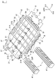
- FIG. 1 It is a perspective view which shows the battery frame attached to the automobile which concerns on this invention. It is a perspective view which shows the state which the battery frame of FIG. 1 is attached to the underfloor of an automobile body. It is sectional drawing which follows the line III-III of FIG. It is sectional drawing along the IV-IV line of FIG. It is an enlarged cross-sectional view which shows the main part of the bottom frame of FIG. It is sectional drawing along the VI-VI line of FIG. It is a bottom view which shows the underfloor including the battery frame and the rear suspension of the automobile which concerns on this invention. It is a bottom view which shows the battery frame and the rear suspension of the automobile which concerns on this invention. It is a top view which shows the battery frame and the rear suspension of the automobile which concerns on this invention. It is a side view which shows the battery frame and the rear suspension of the automobile which concerns on this invention. It is XI arrow view of FIG. It is sectional drawing which follows the XII-XII line of FIG.
- FIG. 1 is a perspective view showing a battery frame constituting the vehicle-mounted battery cooling device of the present invention
- FIG. 2 is a perspective view showing a state in which the battery frame of FIG. 1 is attached to the underfloor of an automobile body
- FIG. 1 is a cross-sectional view taken along line III-III
- FIG. 4 is a cross-sectional view taken along line IV-IV of FIG. 1
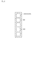
- FIG. 5 is an enlarged cross-sectional view showing a main part of the bottom frame of FIG. It is sectional drawing along the VI-VI line of FIG.
- the automobile 1 is attached to a structural member behind the floor of an automobile body 2, supports a battery frame 3 for accommodating a battery 4, a rear suspension 6, and is attached to a rear floor side member 26. It includes a rear suspension member assembly 61.
- the battery frame 3 includes a plate-shaped bottom frame 31 and a plurality of plate-shaped side frames 32, 33, 34, 35 fixed to the outer peripheral portion of the bottom frame 31.
- the side frames 32 to 35 of the present embodiment are composed of four members, but the present invention is not limited to this, and may be composed of less than four or five or more side frames.
- the bottom frame 31 and the side frames 32 to 35 are not particularly limited, but can be made of an extruded product of aluminum. It will be excellent.
- FIG. 4 is a cross-sectional view taken along the line IV-IV of FIG. 1, showing a vertical cross section of the left and right side frames 32 and 33 of the battery frame 3 and the front and rear side frames 34 and 35.
- the four side frame frames 32 to 35 basically all have the same hollow cross-sectional structure having ribs 321 partially.
- the bottom frame 31 is formed into a single flat plate by welding and joining six sub-bottom frames 31A to 31F divided by dividing lines along the front-rear direction of the automobile body 2. That is, one sub-bottom frame is composed of one extruded product from the front end to the rear end of the bottom frame 31.
- the bottom frame 31 has a hollow cross-sectional structure partially having ribs 314, and has an upper plate 311, a lower plate 312 facing the lower plate 312 via the hollow portion 313, and the hollow portion 313. It is a hollow plate-like frame having a rib 314 connecting the upper plate 311 and the lower plate 312 in the above.
- FIG. 5 is an enlarged cross-sectional view showing a main part of the bottom frame 31, but since the bottom frame 31 is made of an extruded product, it has a cross-sectional structure shown in FIG. 5 from the front end to the rear end of the bottom frame 31. Has been done. Therefore, the flow path 51 is also formed from the front end to the rear end of the bottom frame 31.
- the cooling heat of the liquid refrigerant flowing through the flow path 51 can be easily transferred to the upper plate 311.
- the cooling heat of the liquid refrigerant can be prevented from escaping from the lower plate 312.
- the battery frame 3 shown in FIG. 1 four side frames 32 to 35 are fixed to the outer peripheral portion of the bottom frame 31 by welding or the like, and the battery 4 is the bottom frame 31 and the automobile body 2 facing the bottom frame 31.
- the bottom frame 31 and the side frames 32 to 35 are housed in contact with at least one of them.
- Reference numeral 36 shown in FIG. 1 is a partition plate fixed to the upper surface of the bottom frame 31 by welding or the like.
- Battery 4 (also referred to as an assembled battery) includes a plurality of battery modules 41, and each battery module is housed in a rectangular parallelepiped module case. Although not shown, a plurality of thin batteries (also referred to as single batteries) are stored in a stacked state inside the module case. In the present embodiment, the plurality of battery modules 41 are arranged and fixed side by side on the surface of the bottom frame 31 so that each main surface 411 of the plurality of battery modules 41 is perpendicular to the surface of the bottom frame 31. The module.
- the plurality of battery modules 41 are juxtaposed and fixed on the surface of the bottom frame 31 so that each side surface 412 of the plurality of battery modules 41 is in contact with the surface of the bottom frame 31.
- the battery frame 3 of the present embodiment is attached over substantially the entire range from the front portion of the front floor panel 23 of the floor back surface 21 of the automobile body 2 to the rear floor panel 24.
- Reference numeral 22 indicates a dash panel, and 25 indicates a sill.
- the battery 4 shown in the lower left of the figure is mounted on the five compartments from the front partitioned by the partition plate 36, and the partition plate 36 partitions the battery frame 3.
- a battery 4 in which a smaller amount of battery modules 41 are arranged is mounted in the rearmost section.
- the refrigerant circulator 5 of the present embodiment includes a flow path 51 through which the liquid refrigerant flows, a pump 52 through which the liquid refrigerant flows, a cooler 53 for cooling the liquid refrigerant, and a refrigerant tank 54. ..
- a refrigerant of the present embodiment an antifreeze liquid (long life coolant LLC) containing ethylene glycol as a main component can be used.
- the cooler 53 cools the liquid refrigerant composed of antifreeze by exchanging heat with the refrigerant in the cooling cycle of the automobile air conditioner mounted on the automobile.
- the battery frame 3 configured in this way is attached to the floor back surface 21 of the automobile body 2 by using a plurality of brackets 37 as shown in FIG. 3 after closing the upper surface with the cover 38.
- the left and right sides of the battery frame 3 are attached to the sill inner panel 251 or the sill outer panel 252 of the sill 25 which is a structural member of the automobile body 2.
- the rear end portion of the battery frame 3 is attached to the bracket 261 of the rear floor side member 26 which is a structural member of the automobile body 2 by using the bracket 37.
- the front end side of the battery frame 3 is also directly or indirectly attached to the structural member of the front floor panel in the same manner. Therefore, since the entire six surfaces of the battery frame 3 are mechanically fixed by the bottom frame 31, the side frames 32 to 35, and the cover 38, the battery frame 3 is fixed to the floor back surface 21 of the automobile body 2. It is a solid object.
- the rear suspension 6 is a suspension device including a suspension arm for supporting the rear wheels, a coil spring, a shock absorber (damper), a torsion bar, and a lateral rod, if necessary, although details of the rear suspension 6 are not shown. Yes, the shock absorber is shown as the rear suspension 6 in the side view of FIG.
- the automobile 1 according to the present invention is not particularly limited to the type of the rear suspension 6, and various types of rear suspension can be applied.
- the rear suspension 6 is supported by the rear suspension member assembly 61, and the rear suspension member assembly 61 is attached to the rear floor side member 26.
- the rear floor side member 26 is a structural member of the automobile body 2, and extends from the front end to the rear end on each of the left and right side portions of the back of the floor of the rear floor panel 24 and is fixed by welding or the like.
- FIG. 7 is a bottom view showing the underfloor including the battery frame and the rear suspension of the automobile according to the present invention
- FIG. 8 is a bottom view showing the battery frame and the rear suspension of FIG. 7 extracted
- FIG. 9 is FIG. 10 is a side view showing the battery frame and the rear suspension of the automobile according to the present invention
- FIG. 11 is a XI arrow view of FIG. 9
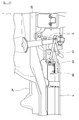
- FIG. 12 is a side view showing the battery frame and the rear suspension of the automobile according to the present invention. It is sectional drawing along the XII-XII line of FIG.
- the rear suspension member assembly 61 is a structural member formed by joining a plurality of pressed steel plates by welding or the like, and as shown in the plan view of FIG. 9, the left front mounting portion 621 and the rear mounting portion 622 A first rear suspension member 62 formed by being curved so as to suspend the rear suspension member 62, and a second rear suspension member 63 formed by being curved so as to suspend the front mounting portion 631 and the rear mounting portion 632 on the right side. , The first rear suspension member 62 and the second rear suspension member 63 are included, and two third rear suspension members 64 and 64 are suspended at the front and rear of the vehicle, respectively.
- the rear suspension member assembly 61 is attached to the rear floor side member 26 at the left and right front mounting portions 621 and 631 and the left and right rear mounting portions 622 and 632, respectively.
- an insulator (not shown) or the like is provided between the left and right front mounting portions 621, 631 and the rear floor side member 26, and between the left and right rear mounting portions 622, 632 and the rear floor side member 26. Be intervened.
- pin stay panels 65 extending to the front of the vehicle are fixed to the front portions of the first rear suspension member 62 and the second rear suspension member 63 by welding or the like.
- the pin stay panel 65 is a part obtained by pressing a steel plate, but is a separate member from the first rear suspension member 62 and the second rear suspension member 63, and constitutes the first fragile portion of the rear suspension member assembly 61. .. Therefore, at the time of a rear collision, the pin stay panel 65 of the rear suspension member assembly 61 is set to have a strength of first buckling.
- the first mounting portion 66 is provided at the tip of the pin stay panel 65.
- the first mounting portion 66 is located in front of the vehicle with respect to the left and right front mounting portions 621 and 63, and the rear suspension member assembly 61 is mounted on the battery frame 3 in the first mounting portion 66.
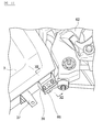
- a bolt hole (not shown) through which the bolt 67 is inserted is formed at the tip of the pin stay panel 65.
- brackets 39 having bolt holes (not shown) through which bolts 67 are inserted are fixed to the left and right sides of the rear portion of the battery frame 3 by welding or the like.
- the bolt holes of the pin stay panel 65 and the bolt holes of the bracket 39 are formed at corresponding positions so that the bolt 67 can be inserted.
- the first mounting portion 66 at the tip of the pin stay panel 65 is mounted on the bracket 39 of the battery frame 3 by using the bolt 67 and the nut 68.
- Reference numeral 69 is a nut plate that prevents the nut 68 from rotating when the bolt 67 is tightened.
- the bolt 67 of the present embodiment has a strength that constitutes a fragile portion of the rear suspension member assembly 61 next to the pin stay panel 65. That is, at the time of a rear collision, the strength of the rear suspension member assembly 61 is set to buckle next to the pin stay panel 65.
- the rear suspension member assembly 61 is attached to the rear floor side member 26 at four points, the left and right front mounting portions 621 and 631, and the left and right rear mounting portions 622 and 632, respectively.
- the first mounting portions 66 provided in front of the left and right front mounting portions 621 and 631 are attached to the left and right rear ends of the battery frame 3, and the rear suspension member assembly 61 is attached to the automobile body 2 at 6 points. It is attached to.
- the battery frame 3 which is attached to the sill 25 and the rear floor side member 26 which are structural members of the floor back surface 21 of the automobile body 2 and houses the battery 4 and the rear suspension.
- the rear suspension member assembly 61 is provided with a rear suspension member assembly 61 that supports 6 and is attached to the rear floor side member 26.
- the rear suspension member assembly 61 has at least left and right front mounting portions 621 and 631 and left and right rear mounting.
- the portions 622 and 632 are attached to the rear floor side member 26, and are attached to the battery frame 3 at the first attachment portion 66 in front of the left and right front attachment portions 621 and 631.
- the battery frame 3 Since the entire six surfaces of the battery frame 3 are mechanically fixed by the bottom frame 31, the side frames 32 to 35, and the cover 38, the battery frame 3 is firmly fixed to the floor back surface 21 of the automobile body 2. It is an object. Therefore, even if the left and right front ends of the rear suspension member assembly 61 are not attached to the automobile body 2 via a subframe or the like of another part, the battery frame 3 has the same strength as this type of subframe, so that steering stability is achieved. It is possible to reduce the weight by reducing the number of parts without impairing the weight. In addition to this, by attaching the first mounting portion in front of the rear suspension member assembly to the battery frame, the battery frame can be expanded rearward to the position of the rear suspension. As a result, the battery can be mounted in front of the rear suspension without interfering with the rear suspension member.
- the left and right side portions of the battery frame 3 are attached to the sill 25 of the automobile body 2, and the left and right rear ends thereof are attached to the rear floor side member 26, and the rear suspension.
- the first mounting portion 66 of the member assembly 61 is mounted on each of the left and right rear end portions of the battery frame 3. That is, since the entire six surfaces of the battery frame 3 are mechanically fixed by the bottom frame 31, the side frames 32 to 35, and the cover 38, the battery frame 3 is fixed to the floor back surface 21 of the automobile body 2. It is a solid object. Therefore, it is possible to reduce the weight by reducing the number of parts without impairing the steering stability.
- the battery can be mounted in front of the rear suspension without interfering with the rear suspension member.
- the rear suspension member assembly 61 includes a first rear suspension member 62 that suspends the left front mounting portion 621 and the rear mounting portion 622, and a right front mounting portion 631.
- the first mounting portion includes a second rear suspension member 63 for suspending the rear mounting portion 632, and third rear suspension members 64 and 64 for suspending the first rear suspension member 62 and the second rear suspension member 63.
- the 66 is provided on the pin stay panel 65 extending from the front of each of the first rear suspension member 62 and the second rear suspension member 63 to the front of the vehicle, and is fixed to each of the left and right rear ends of the battery frame 3.
- the first mounting portion 66 is attached to the bracket 39 via the bolt 67 and the nut 68.
- the pin stay panel 65 is a separate member from the first rear suspension member 62 and the second rear suspension member 63, and constitutes a fragile portion of the rear suspension member assembly 61. As a result, at the time of a rear collision, the pin stay panel 65 of the rear suspension member assembly 61 buckles first, so that the collision impact can be absorbed mainly only by the pin stay panel 65.
- the bolt 67 used for the first mounting portion 66 constitutes a fragile portion of the rear suspension member assembly 61 next to the pin stay panel 65.
- the bolt 67 buckles next to the pin stay panel 65 in the rear suspension member assembly 61, so that the collision impact can be mainly absorbed by the pin stay panel 65 and the bolt 67.
- Bracket 4 Battery 41... Battery module 411... Main surface 412... Side 5... Refrigerator circulator 51... Flow path 52... Pump 53... Cooler 54... Refrigerator tank 6... Rear suspension 61... Rear suspension member assembly 62... First rear suspension member 621 ... Front mounting part 622 ... Rear mounting part 63 ... Second rear suspension member 631 ... Front mounting part 632 ... Rear mounting part 64 ... Third rear suspension member 65 ... Pin stay panel 66 ... First mounting part 67 ... Bolt 68 ... nut 69 ... nut plate
Landscapes
- Engineering & Computer Science (AREA)
- Chemical & Material Sciences (AREA)
- Combustion & Propulsion (AREA)
- Transportation (AREA)
- Mechanical Engineering (AREA)
- Body Structure For Vehicles (AREA)
- Arrangement Or Mounting Of Propulsion Units For Vehicles (AREA)
Priority Applications (5)
| Application Number | Priority Date | Filing Date | Title |
|---|---|---|---|
| US17/754,704 US12103376B2 (en) | 2019-10-09 | 2019-10-09 | Automobile |
| JP2021551008A JP7272452B2 (ja) | 2019-10-09 | 2019-10-09 | 自動車 |
| PCT/JP2019/039843 WO2021070288A1 (ja) | 2019-10-09 | 2019-10-09 | 自動車 |
| CN201980101134.3A CN114585530A (zh) | 2019-10-09 | 2019-10-09 | 汽车 |
| EP19948209.2A EP4043256B1 (en) | 2019-10-09 | 2019-10-09 | Automobile |
Applications Claiming Priority (1)
| Application Number | Priority Date | Filing Date | Title |
|---|---|---|---|
| PCT/JP2019/039843 WO2021070288A1 (ja) | 2019-10-09 | 2019-10-09 | 自動車 |
Publications (1)
| Publication Number | Publication Date |
|---|---|
| WO2021070288A1 true WO2021070288A1 (ja) | 2021-04-15 |
Family
ID=75437362
Family Applications (1)
| Application Number | Title | Priority Date | Filing Date |
|---|---|---|---|
| PCT/JP2019/039843 Ceased WO2021070288A1 (ja) | 2019-10-09 | 2019-10-09 | 自動車 |
Country Status (5)
| Country | Link |
|---|---|
| US (1) | US12103376B2 (https=) |
| EP (1) | EP4043256B1 (https=) |
| JP (1) | JP7272452B2 (https=) |
| CN (1) | CN114585530A (https=) |
| WO (1) | WO2021070288A1 (https=) |
Cited By (4)
| Publication number | Priority date | Publication date | Assignee | Title |
|---|---|---|---|---|
| WO2022249409A1 (ja) * | 2021-05-27 | 2022-12-01 | 日産自動車株式会社 | バッテリケース |
| CN116638952A (zh) * | 2022-02-24 | 2023-08-25 | 马自达汽车株式会社 | 车体构造 |
| JP2023122990A (ja) * | 2022-02-24 | 2023-09-05 | マツダ株式会社 | 車体構造 |
| US12286019B2 (en) * | 2021-09-30 | 2025-04-29 | Mazda Motor Corporation | Vehicle-body structure with a battery cover for improved aerodynamic performance |
Families Citing this family (5)
| Publication number | Priority date | Publication date | Assignee | Title |
|---|---|---|---|---|
| JP7272452B2 (ja) * | 2019-10-09 | 2023-05-12 | 日産自動車株式会社 | 自動車 |
| JP7396321B2 (ja) * | 2021-03-31 | 2023-12-12 | トヨタ自動車株式会社 | 蓄電ユニットおよび車両 |
| JP7707662B2 (ja) * | 2021-06-01 | 2025-07-15 | マツダ株式会社 | 車体構造 |
| JP2023122984A (ja) * | 2022-02-24 | 2023-09-05 | マツダ株式会社 | 後部車体構造 |
| JP2024044115A (ja) * | 2022-09-20 | 2024-04-02 | トヨタ自動車株式会社 | 車両 |
Citations (3)
| Publication number | Priority date | Publication date | Assignee | Title |
|---|---|---|---|---|
| JP2004161158A (ja) | 2002-11-14 | 2004-06-10 | Nissan Motor Co Ltd | 電気自動車のバッテリ搭載構造 |
| JP2017222332A (ja) * | 2016-06-17 | 2017-12-21 | トヨタ自動車株式会社 | 車両フロア構造 |
| JP2019156029A (ja) * | 2018-03-09 | 2019-09-19 | トヨタ自動車株式会社 | 車両下部構造 |
Family Cites Families (25)
| Publication number | Priority date | Publication date | Assignee | Title |
|---|---|---|---|---|
| JP5071538B2 (ja) * | 2010-09-03 | 2012-11-14 | トヨタ自動車株式会社 | 車両用電池搭載構造 |
| JP5411235B2 (ja) | 2011-11-15 | 2014-02-12 | 本田技研工業株式会社 | 自動車の車体下部構造 |
| JP5906689B2 (ja) * | 2011-11-22 | 2016-04-20 | トヨタ自動車株式会社 | 車両用電池搭載構造 |
| US8608230B2 (en) * | 2012-04-13 | 2013-12-17 | Toyota Motor Engineering & Manufacturing North America, Inc. | Localized energy dissipation structures for vehicles |
| US8833839B2 (en) * | 2012-04-13 | 2014-09-16 | Toyota Motor Engineering & Manufacturing North America, Inc. | Impact protection structures for vehicles |
| US9937781B1 (en) * | 2016-12-19 | 2018-04-10 | GM Global Technology Operations LLC | Battery pack mounting architecture with shear plate for electric drive motor vehicles |
| JP6946718B2 (ja) * | 2017-04-28 | 2021-10-06 | トヨタ自動車株式会社 | 車両前部構造 |
| JP6816664B2 (ja) * | 2017-06-30 | 2021-01-20 | トヨタ自動車株式会社 | 車体前部構造 |
| JP6791045B2 (ja) * | 2017-07-18 | 2020-11-25 | トヨタ自動車株式会社 | 車体前部構造 |
| US11110785B2 (en) * | 2017-08-02 | 2021-09-07 | Toyota Jidosha Kabushiki Kaisha | Vehicle rear portion structure |
| KR102440612B1 (ko) * | 2017-12-15 | 2022-09-05 | 현대자동차 주식회사 | 측방 차체 보강구조 |
| JP7067142B2 (ja) * | 2018-03-09 | 2022-05-16 | トヨタ自動車株式会社 | 車両下部構造 |
| JP6988590B2 (ja) * | 2018-03-09 | 2022-01-05 | トヨタ自動車株式会社 | 車両後部構造 |
| JP7006390B2 (ja) * | 2018-03-09 | 2022-01-24 | トヨタ自動車株式会社 | 車両の下部車体構造 |
| JP7167630B2 (ja) * | 2018-10-30 | 2022-11-09 | トヨタ自動車株式会社 | 車両前部構造 |
| JP7143768B2 (ja) * | 2019-01-09 | 2022-09-29 | トヨタ自動車株式会社 | 車両下部構造 |
| US10843545B2 (en) * | 2019-03-26 | 2020-11-24 | Ford Global Technologies, Llc | Connected battery pack assembly and connecting method |
| CN114502401B (zh) * | 2019-07-01 | 2025-03-07 | Sabic环球技术有限责任公司 | 用于车辆电池包框架的混合能量吸收 |
| JP7272452B2 (ja) * | 2019-10-09 | 2023-05-12 | 日産自動車株式会社 | 自動車 |
| DE102019133496B3 (de) * | 2019-12-09 | 2020-12-17 | Dr. Ing. H.C. F. Porsche Aktiengesellschaft | Teilkarosserie für ein wenigstens teilweise elektrisch betriebenes Kraftfahrzeug und Kraftfahrzeug |
| JP2023122984A (ja) * | 2022-02-24 | 2023-09-05 | マツダ株式会社 | 後部車体構造 |
| JP7700702B2 (ja) * | 2022-02-24 | 2025-07-01 | マツダ株式会社 | 後部車体構造 |
| JP7796570B2 (ja) * | 2022-03-24 | 2026-01-09 | 本田技研工業株式会社 | 車体の装置保護構造 |
| JP2024017605A (ja) * | 2022-07-28 | 2024-02-08 | 本田技研工業株式会社 | 車体後部構造 |
| CN117842197A (zh) * | 2022-09-30 | 2024-04-09 | 本田技研工业株式会社 | 车辆前部结构 |
-
2019
- 2019-10-09 JP JP2021551008A patent/JP7272452B2/ja active Active
- 2019-10-09 EP EP19948209.2A patent/EP4043256B1/en active Active
- 2019-10-09 WO PCT/JP2019/039843 patent/WO2021070288A1/ja not_active Ceased
- 2019-10-09 CN CN201980101134.3A patent/CN114585530A/zh active Pending
- 2019-10-09 US US17/754,704 patent/US12103376B2/en active Active
Patent Citations (3)
| Publication number | Priority date | Publication date | Assignee | Title |
|---|---|---|---|---|
| JP2004161158A (ja) | 2002-11-14 | 2004-06-10 | Nissan Motor Co Ltd | 電気自動車のバッテリ搭載構造 |
| JP2017222332A (ja) * | 2016-06-17 | 2017-12-21 | トヨタ自動車株式会社 | 車両フロア構造 |
| JP2019156029A (ja) * | 2018-03-09 | 2019-09-19 | トヨタ自動車株式会社 | 車両下部構造 |
Non-Patent Citations (1)
| Title |
|---|
| See also references of EP4043256A4 |
Cited By (12)
| Publication number | Priority date | Publication date | Assignee | Title |
|---|---|---|---|---|
| WO2022249409A1 (ja) * | 2021-05-27 | 2022-12-01 | 日産自動車株式会社 | バッテリケース |
| JPWO2022249409A1 (https=) * | 2021-05-27 | 2022-12-01 | ||
| CN117396350A (zh) * | 2021-05-27 | 2024-01-12 | 日产自动车株式会社 | 电池外壳 |
| JP7563592B2 (ja) | 2021-05-27 | 2024-10-08 | 日産自動車株式会社 | バッテリケース |
| EP4349627A4 (en) * | 2021-05-27 | 2024-10-30 | Nissan Motor Co., Ltd. | BATTERY CASE |
| US12496891B2 (en) | 2021-05-27 | 2025-12-16 | Nissan Motor Co., Ltd. | Battery case |
| US12286019B2 (en) * | 2021-09-30 | 2025-04-29 | Mazda Motor Corporation | Vehicle-body structure with a battery cover for improved aerodynamic performance |
| CN116638952A (zh) * | 2022-02-24 | 2023-08-25 | 马自达汽车株式会社 | 车体构造 |
| JP2023122990A (ja) * | 2022-02-24 | 2023-09-05 | マツダ株式会社 | 車体構造 |
| JP2023122993A (ja) * | 2022-02-24 | 2023-09-05 | マツダ株式会社 | 車体構造 |
| JP7718292B2 (ja) | 2022-02-24 | 2025-08-05 | マツダ株式会社 | 車体構造 |
| JP7764781B2 (ja) | 2022-02-24 | 2025-11-06 | マツダ株式会社 | 車体構造 |
Also Published As
| Publication number | Publication date |
|---|---|
| JPWO2021070288A1 (https=) | 2021-04-15 |
| CN114585530A (zh) | 2022-06-03 |
| JP7272452B2 (ja) | 2023-05-12 |
| EP4043256A1 (en) | 2022-08-17 |
| EP4043256A4 (en) | 2022-10-12 |
| US20230249533A1 (en) | 2023-08-10 |
| US12103376B2 (en) | 2024-10-01 |
| EP4043256B1 (en) | 2023-12-06 |
Similar Documents
| Publication | Publication Date | Title |
|---|---|---|
| WO2021070288A1 (ja) | 自動車 | |
| US10597081B2 (en) | Vehicle front portion structure | |
| JP7101489B2 (ja) | 電池モジュールの車両搭載構造 | |
| US10710638B2 (en) | Vehicle lower portion structure | |
| JP2014530787A (ja) | 後輪駆動方式の、プラグインハイブリッド電気自動車のモジュラーサブフレームアセンブリ及びその組立方法 | |
| WO2021066180A1 (ja) | 自動車の下部構造 | |
| KR102322265B1 (ko) | 전기 자동차용 프레임 | |
| US20120169089A1 (en) | Rear Vehicle Torque Box | |
| US12555859B2 (en) | Battery mounting structure for vehicle | |
| JPH05201356A (ja) | 電気自動車の車体構造 | |
| JPH0747842A (ja) | 電気自動車用の車体 | |
| JP7211987B2 (ja) | 車体下部構造 | |
| US12447808B2 (en) | Structural assembly and vehicle having structural assembly | |
| US12233701B2 (en) | Structural assembly and vehicle having structural assembly | |
| JP7396217B2 (ja) | 電動車両 | |
| US12221012B2 (en) | Battery unit for vehicle and underbody of vehicle including the same | |
| JP2021070386A (ja) | 車両用電池ケース構造体 | |
| CN113135235B (zh) | 车身下部构造 | |
| CN113795397A (zh) | 具有机动车车身和蓄能单元组件的机动车 | |
| US11485415B2 (en) | Vehicle body lower structure | |
| CN112208638A (zh) | 一种车架及电动车辆 | |
| JP2016043907A (ja) | 車両のバッテリ搭載構造 | |
| US9022459B2 (en) | Assembly for fastening of a steering column for a motor vehicle | |
| CN102811898B (zh) | 具有可倾斜的驾驶室的正向控制卡车的底盘 | |
| US20240014496A1 (en) | Mounting structure for electric vehicle |
Legal Events
| Date | Code | Title | Description |
|---|---|---|---|
| 121 | Ep: the epo has been informed by wipo that ep was designated in this application |
Ref document number: 19948209 Country of ref document: EP Kind code of ref document: A1 |
|
| ENP | Entry into the national phase |
Ref document number: 2021551008 Country of ref document: JP Kind code of ref document: A |
|
| NENP | Non-entry into the national phase |
Ref country code: DE |
|
| ENP | Entry into the national phase |
Ref document number: 2019948209 Country of ref document: EP Effective date: 20220509 |