WO2021070288A1 - Automobile - Google Patents
Automobile Download PDFInfo
- Publication number
- WO2021070288A1 WO2021070288A1 PCT/JP2019/039843 JP2019039843W WO2021070288A1 WO 2021070288 A1 WO2021070288 A1 WO 2021070288A1 JP 2019039843 W JP2019039843 W JP 2019039843W WO 2021070288 A1 WO2021070288 A1 WO 2021070288A1
- Authority
- WO
- WIPO (PCT)
- Prior art keywords
- rear suspension
- suspension member
- battery
- attached
- mounting portion
- Prior art date
Links
Images


Classifications
-
- B—PERFORMING OPERATIONS; TRANSPORTING
- B60—VEHICLES IN GENERAL
- B60K—ARRANGEMENT OR MOUNTING OF PROPULSION UNITS OR OF TRANSMISSIONS IN VEHICLES; ARRANGEMENT OR MOUNTING OF PLURAL DIVERSE PRIME-MOVERS IN VEHICLES; AUXILIARY DRIVES FOR VEHICLES; INSTRUMENTATION OR DASHBOARDS FOR VEHICLES; ARRANGEMENTS IN CONNECTION WITH COOLING, AIR INTAKE, GAS EXHAUST OR FUEL SUPPLY OF PROPULSION UNITS IN VEHICLES
- B60K1/00—Arrangement or mounting of electrical propulsion units
- B60K1/04—Arrangement or mounting of electrical propulsion units of the electric storage means for propulsion
-
- B—PERFORMING OPERATIONS; TRANSPORTING
- B62—LAND VEHICLES FOR TRAVELLING OTHERWISE THAN ON RAILS
- B62D—MOTOR VEHICLES; TRAILERS
- B62D25/00—Superstructure or monocoque structure sub-units; Parts or details thereof not otherwise provided for
- B62D25/20—Floors or bottom sub-units
- B62D25/2009—Floors or bottom sub-units in connection with other superstructure subunits
- B62D25/2027—Floors or bottom sub-units in connection with other superstructure subunits the subunits being rear structures
-
- B—PERFORMING OPERATIONS; TRANSPORTING
- B62—LAND VEHICLES FOR TRAVELLING OTHERWISE THAN ON RAILS
- B62D—MOTOR VEHICLES; TRAILERS
- B62D25/00—Superstructure or monocoque structure sub-units; Parts or details thereof not otherwise provided for
- B62D25/20—Floors or bottom sub-units
- B62D25/2009—Floors or bottom sub-units in connection with other superstructure subunits
- B62D25/2036—Floors or bottom sub-units in connection with other superstructure subunits the subunits being side panels, sills or pillars
-
- B—PERFORMING OPERATIONS; TRANSPORTING
- B60—VEHICLES IN GENERAL
- B60K—ARRANGEMENT OR MOUNTING OF PROPULSION UNITS OR OF TRANSMISSIONS IN VEHICLES; ARRANGEMENT OR MOUNTING OF PLURAL DIVERSE PRIME-MOVERS IN VEHICLES; AUXILIARY DRIVES FOR VEHICLES; INSTRUMENTATION OR DASHBOARDS FOR VEHICLES; ARRANGEMENTS IN CONNECTION WITH COOLING, AIR INTAKE, GAS EXHAUST OR FUEL SUPPLY OF PROPULSION UNITS IN VEHICLES
- B60K1/00—Arrangement or mounting of electrical propulsion units
- B60K1/04—Arrangement or mounting of electrical propulsion units of the electric storage means for propulsion
- B60K2001/0405—Arrangement or mounting of electrical propulsion units of the electric storage means for propulsion characterised by their position
- B60K2001/0438—Arrangement under the floor
-
- B—PERFORMING OPERATIONS; TRANSPORTING
- B60—VEHICLES IN GENERAL
- B60Y—INDEXING SCHEME RELATING TO ASPECTS CROSS-CUTTING VEHICLE TECHNOLOGY
- B60Y2400/00—Special features of vehicle units
- B60Y2400/86—Suspension systems
Definitions
- the present invention relates to an automobile, and particularly to an attachment structure of a rear suspension member of an automobile in which a battery is mounted on the floor.
- Patent Document 1 It is known that an automobile is behind the rear floor of an automobile body and has a battery mounted behind the rear suspension.
- the problem to be solved by the present invention is to provide an automobile capable of mounting a battery in front of the rear suspension without interfering with the rear suspension member.
- the left and right front mounting portions and the left and right rear mounting portions of the rear suspension member assembly are mounted on the rear floor side members, and further, the first mounting portion in front of the vehicle front of the left and right front mounting portions.
- the battery frame since the battery frame is attached to the structural member under the floor of the automobile body and is rigid, the rear suspension member assembly can be sufficiently supported and the steering stability can be maintained.
- the battery frame by attaching the first mounting portion in front of the rear suspension member assembly to the battery frame, the battery frame can be expanded rearward to the position of the rear suspension. As a result, the battery can be mounted in front of the rear suspension without interfering with the rear suspension member.
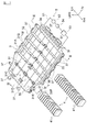
- FIG. 1 It is a perspective view which shows the battery frame attached to the automobile which concerns on this invention. It is a perspective view which shows the state which the battery frame of FIG. 1 is attached to the underfloor of an automobile body. It is sectional drawing which follows the line III-III of FIG. It is sectional drawing along the IV-IV line of FIG. It is an enlarged cross-sectional view which shows the main part of the bottom frame of FIG. It is sectional drawing along the VI-VI line of FIG. It is a bottom view which shows the underfloor including the battery frame and the rear suspension of the automobile which concerns on this invention. It is a bottom view which shows the battery frame and the rear suspension of the automobile which concerns on this invention. It is a top view which shows the battery frame and the rear suspension of the automobile which concerns on this invention. It is a side view which shows the battery frame and the rear suspension of the automobile which concerns on this invention. It is XI arrow view of FIG. It is sectional drawing which follows the XII-XII line of FIG.
- FIG. 1 is a perspective view showing a battery frame constituting the vehicle-mounted battery cooling device of the present invention
- FIG. 2 is a perspective view showing a state in which the battery frame of FIG. 1 is attached to the underfloor of an automobile body
- FIG. 1 is a cross-sectional view taken along line III-III
- FIG. 4 is a cross-sectional view taken along line IV-IV of FIG. 1
- FIG. 5 is an enlarged cross-sectional view showing a main part of the bottom frame of FIG. It is sectional drawing along the VI-VI line of FIG.
- the automobile 1 is attached to a structural member behind the floor of an automobile body 2, supports a battery frame 3 for accommodating a battery 4, a rear suspension 6, and is attached to a rear floor side member 26. It includes a rear suspension member assembly 61.
- the battery frame 3 includes a plate-shaped bottom frame 31 and a plurality of plate-shaped side frames 32, 33, 34, 35 fixed to the outer peripheral portion of the bottom frame 31.
- the side frames 32 to 35 of the present embodiment are composed of four members, but the present invention is not limited to this, and may be composed of less than four or five or more side frames.
- the bottom frame 31 and the side frames 32 to 35 are not particularly limited, but can be made of an extruded product of aluminum. It will be excellent.
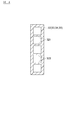
- FIG. 4 is a cross-sectional view taken along the line IV-IV of FIG. 1, showing a vertical cross section of the left and right side frames 32 and 33 of the battery frame 3 and the front and rear side frames 34 and 35.
- the four side frame frames 32 to 35 basically all have the same hollow cross-sectional structure having ribs 321 partially.
- the bottom frame 31 is formed into a single flat plate by welding and joining six sub-bottom frames 31A to 31F divided by dividing lines along the front-rear direction of the automobile body 2. That is, one sub-bottom frame is composed of one extruded product from the front end to the rear end of the bottom frame 31.
- the bottom frame 31 has a hollow cross-sectional structure partially having ribs 314, and has an upper plate 311, a lower plate 312 facing the lower plate 312 via the hollow portion 313, and the hollow portion 313. It is a hollow plate-like frame having a rib 314 connecting the upper plate 311 and the lower plate 312 in the above.
- FIG. 5 is an enlarged cross-sectional view showing a main part of the bottom frame 31, but since the bottom frame 31 is made of an extruded product, it has a cross-sectional structure shown in FIG. 5 from the front end to the rear end of the bottom frame 31. Has been done. Therefore, the flow path 51 is also formed from the front end to the rear end of the bottom frame 31.
- the cooling heat of the liquid refrigerant flowing through the flow path 51 can be easily transferred to the upper plate 311.
- the cooling heat of the liquid refrigerant can be prevented from escaping from the lower plate 312.
- the battery frame 3 shown in FIG. 1 four side frames 32 to 35 are fixed to the outer peripheral portion of the bottom frame 31 by welding or the like, and the battery 4 is the bottom frame 31 and the automobile body 2 facing the bottom frame 31.
- the bottom frame 31 and the side frames 32 to 35 are housed in contact with at least one of them.
- Reference numeral 36 shown in FIG. 1 is a partition plate fixed to the upper surface of the bottom frame 31 by welding or the like.
- Battery 4 (also referred to as an assembled battery) includes a plurality of battery modules 41, and each battery module is housed in a rectangular parallelepiped module case. Although not shown, a plurality of thin batteries (also referred to as single batteries) are stored in a stacked state inside the module case. In the present embodiment, the plurality of battery modules 41 are arranged and fixed side by side on the surface of the bottom frame 31 so that each main surface 411 of the plurality of battery modules 41 is perpendicular to the surface of the bottom frame 31. The module.
- the plurality of battery modules 41 are juxtaposed and fixed on the surface of the bottom frame 31 so that each side surface 412 of the plurality of battery modules 41 is in contact with the surface of the bottom frame 31.
- the battery frame 3 of the present embodiment is attached over substantially the entire range from the front portion of the front floor panel 23 of the floor back surface 21 of the automobile body 2 to the rear floor panel 24.
- Reference numeral 22 indicates a dash panel, and 25 indicates a sill.
- the battery 4 shown in the lower left of the figure is mounted on the five compartments from the front partitioned by the partition plate 36, and the partition plate 36 partitions the battery frame 3.
- a battery 4 in which a smaller amount of battery modules 41 are arranged is mounted in the rearmost section.
- the refrigerant circulator 5 of the present embodiment includes a flow path 51 through which the liquid refrigerant flows, a pump 52 through which the liquid refrigerant flows, a cooler 53 for cooling the liquid refrigerant, and a refrigerant tank 54. ..
- a refrigerant of the present embodiment an antifreeze liquid (long life coolant LLC) containing ethylene glycol as a main component can be used.
- the cooler 53 cools the liquid refrigerant composed of antifreeze by exchanging heat with the refrigerant in the cooling cycle of the automobile air conditioner mounted on the automobile.
- the battery frame 3 configured in this way is attached to the floor back surface 21 of the automobile body 2 by using a plurality of brackets 37 as shown in FIG. 3 after closing the upper surface with the cover 38.
- the left and right sides of the battery frame 3 are attached to the sill inner panel 251 or the sill outer panel 252 of the sill 25 which is a structural member of the automobile body 2.
- the rear end portion of the battery frame 3 is attached to the bracket 261 of the rear floor side member 26 which is a structural member of the automobile body 2 by using the bracket 37.
- the front end side of the battery frame 3 is also directly or indirectly attached to the structural member of the front floor panel in the same manner. Therefore, since the entire six surfaces of the battery frame 3 are mechanically fixed by the bottom frame 31, the side frames 32 to 35, and the cover 38, the battery frame 3 is fixed to the floor back surface 21 of the automobile body 2. It is a solid object.
- the rear suspension 6 is a suspension device including a suspension arm for supporting the rear wheels, a coil spring, a shock absorber (damper), a torsion bar, and a lateral rod, if necessary, although details of the rear suspension 6 are not shown. Yes, the shock absorber is shown as the rear suspension 6 in the side view of FIG.
- the automobile 1 according to the present invention is not particularly limited to the type of the rear suspension 6, and various types of rear suspension can be applied.
- the rear suspension 6 is supported by the rear suspension member assembly 61, and the rear suspension member assembly 61 is attached to the rear floor side member 26.
- the rear floor side member 26 is a structural member of the automobile body 2, and extends from the front end to the rear end on each of the left and right side portions of the back of the floor of the rear floor panel 24 and is fixed by welding or the like.
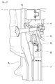
- FIG. 7 is a bottom view showing the underfloor including the battery frame and the rear suspension of the automobile according to the present invention
- FIG. 8 is a bottom view showing the battery frame and the rear suspension of FIG. 7 extracted
- FIG. 9 is FIG. 10 is a side view showing the battery frame and the rear suspension of the automobile according to the present invention
- FIG. 11 is a XI arrow view of FIG. 9
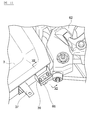
- FIG. 12 is a side view showing the battery frame and the rear suspension of the automobile according to the present invention. It is sectional drawing along the XII-XII line of FIG.
- the rear suspension member assembly 61 is a structural member formed by joining a plurality of pressed steel plates by welding or the like, and as shown in the plan view of FIG. 9, the left front mounting portion 621 and the rear mounting portion 622 A first rear suspension member 62 formed by being curved so as to suspend the rear suspension member 62, and a second rear suspension member 63 formed by being curved so as to suspend the front mounting portion 631 and the rear mounting portion 632 on the right side. , The first rear suspension member 62 and the second rear suspension member 63 are included, and two third rear suspension members 64 and 64 are suspended at the front and rear of the vehicle, respectively.
- the rear suspension member assembly 61 is attached to the rear floor side member 26 at the left and right front mounting portions 621 and 631 and the left and right rear mounting portions 622 and 632, respectively.
- an insulator (not shown) or the like is provided between the left and right front mounting portions 621, 631 and the rear floor side member 26, and between the left and right rear mounting portions 622, 632 and the rear floor side member 26. Be intervened.
- pin stay panels 65 extending to the front of the vehicle are fixed to the front portions of the first rear suspension member 62 and the second rear suspension member 63 by welding or the like.
- the pin stay panel 65 is a part obtained by pressing a steel plate, but is a separate member from the first rear suspension member 62 and the second rear suspension member 63, and constitutes the first fragile portion of the rear suspension member assembly 61. .. Therefore, at the time of a rear collision, the pin stay panel 65 of the rear suspension member assembly 61 is set to have a strength of first buckling.
- the first mounting portion 66 is provided at the tip of the pin stay panel 65.
- the first mounting portion 66 is located in front of the vehicle with respect to the left and right front mounting portions 621 and 63, and the rear suspension member assembly 61 is mounted on the battery frame 3 in the first mounting portion 66.
- a bolt hole (not shown) through which the bolt 67 is inserted is formed at the tip of the pin stay panel 65.
- brackets 39 having bolt holes (not shown) through which bolts 67 are inserted are fixed to the left and right sides of the rear portion of the battery frame 3 by welding or the like.
- the bolt holes of the pin stay panel 65 and the bolt holes of the bracket 39 are formed at corresponding positions so that the bolt 67 can be inserted.
- the first mounting portion 66 at the tip of the pin stay panel 65 is mounted on the bracket 39 of the battery frame 3 by using the bolt 67 and the nut 68.
- Reference numeral 69 is a nut plate that prevents the nut 68 from rotating when the bolt 67 is tightened.
- the bolt 67 of the present embodiment has a strength that constitutes a fragile portion of the rear suspension member assembly 61 next to the pin stay panel 65. That is, at the time of a rear collision, the strength of the rear suspension member assembly 61 is set to buckle next to the pin stay panel 65.
- the rear suspension member assembly 61 is attached to the rear floor side member 26 at four points, the left and right front mounting portions 621 and 631, and the left and right rear mounting portions 622 and 632, respectively.
- the first mounting portions 66 provided in front of the left and right front mounting portions 621 and 631 are attached to the left and right rear ends of the battery frame 3, and the rear suspension member assembly 61 is attached to the automobile body 2 at 6 points. It is attached to.
- the battery frame 3 which is attached to the sill 25 and the rear floor side member 26 which are structural members of the floor back surface 21 of the automobile body 2 and houses the battery 4 and the rear suspension.
- the rear suspension member assembly 61 is provided with a rear suspension member assembly 61 that supports 6 and is attached to the rear floor side member 26.
- the rear suspension member assembly 61 has at least left and right front mounting portions 621 and 631 and left and right rear mounting.
- the portions 622 and 632 are attached to the rear floor side member 26, and are attached to the battery frame 3 at the first attachment portion 66 in front of the left and right front attachment portions 621 and 631.
- the battery frame 3 Since the entire six surfaces of the battery frame 3 are mechanically fixed by the bottom frame 31, the side frames 32 to 35, and the cover 38, the battery frame 3 is firmly fixed to the floor back surface 21 of the automobile body 2. It is an object. Therefore, even if the left and right front ends of the rear suspension member assembly 61 are not attached to the automobile body 2 via a subframe or the like of another part, the battery frame 3 has the same strength as this type of subframe, so that steering stability is achieved. It is possible to reduce the weight by reducing the number of parts without impairing the weight. In addition to this, by attaching the first mounting portion in front of the rear suspension member assembly to the battery frame, the battery frame can be expanded rearward to the position of the rear suspension. As a result, the battery can be mounted in front of the rear suspension without interfering with the rear suspension member.
- the left and right side portions of the battery frame 3 are attached to the sill 25 of the automobile body 2, and the left and right rear ends thereof are attached to the rear floor side member 26, and the rear suspension.
- the first mounting portion 66 of the member assembly 61 is mounted on each of the left and right rear end portions of the battery frame 3. That is, since the entire six surfaces of the battery frame 3 are mechanically fixed by the bottom frame 31, the side frames 32 to 35, and the cover 38, the battery frame 3 is fixed to the floor back surface 21 of the automobile body 2. It is a solid object. Therefore, it is possible to reduce the weight by reducing the number of parts without impairing the steering stability.
- the battery can be mounted in front of the rear suspension without interfering with the rear suspension member.
- the rear suspension member assembly 61 includes a first rear suspension member 62 that suspends the left front mounting portion 621 and the rear mounting portion 622, and a right front mounting portion 631.
- the first mounting portion includes a second rear suspension member 63 for suspending the rear mounting portion 632, and third rear suspension members 64 and 64 for suspending the first rear suspension member 62 and the second rear suspension member 63.
- the 66 is provided on the pin stay panel 65 extending from the front of each of the first rear suspension member 62 and the second rear suspension member 63 to the front of the vehicle, and is fixed to each of the left and right rear ends of the battery frame 3.
- the first mounting portion 66 is attached to the bracket 39 via the bolt 67 and the nut 68.
- the pin stay panel 65 is a separate member from the first rear suspension member 62 and the second rear suspension member 63, and constitutes a fragile portion of the rear suspension member assembly 61. As a result, at the time of a rear collision, the pin stay panel 65 of the rear suspension member assembly 61 buckles first, so that the collision impact can be absorbed mainly only by the pin stay panel 65.
- the bolt 67 used for the first mounting portion 66 constitutes a fragile portion of the rear suspension member assembly 61 next to the pin stay panel 65.
- the bolt 67 buckles next to the pin stay panel 65 in the rear suspension member assembly 61, so that the collision impact can be mainly absorbed by the pin stay panel 65 and the bolt 67.
- Bracket 4 Battery 41... Battery module 411... Main surface 412... Side 5... Refrigerator circulator 51... Flow path 52... Pump 53... Cooler 54... Refrigerator tank 6... Rear suspension 61... Rear suspension member assembly 62... First rear suspension member 621 ... Front mounting part 622 ... Rear mounting part 63 ... Second rear suspension member 631 ... Front mounting part 632 ... Rear mounting part 64 ... Third rear suspension member 65 ... Pin stay panel 66 ... First mounting part 67 ... Bolt 68 ... nut 69 ... nut plate
Abstract
The present invention is provided with: a battery frame (3) that is attached to a structural member on a floor back of an automobile body (2) and accommodates a battery (4); and a rear suspension member assembly (61) that supports a rear suspension (6) and is attached to a rear floor side member (26). In the rear suspension member assembly, at least left and right front side attachment parts (621, 631) and left and right rear side attachment parts (622, 632) are attached to the rear floor side member (26), and a first attachment part (66) further toward the vehicle front than the respective left and right front side attachment parts (621, 631) is attached to the battery frame (3).
Description
本発明は、自動車に関し、特に床裏にバッテリを搭載した自動車のリヤサスペンションメンバの取付構造に関するものである。
The present invention relates to an automobile, and particularly to an attachment structure of a rear suspension member of an automobile in which a battery is mounted on the floor.
自動車ボディのリヤフロアの床裏であって、リヤサスペンションの後方にバッテリを搭載した自動車が知られている(特許文献1)。
It is known that an automobile is behind the rear floor of an automobile body and has a battery mounted behind the rear suspension (Patent Document 1).
しかしながら、航続距離を延ばすためにバッテリ容量をさらに拡大したい場合、上記従来のようにリヤフロアのリヤサスペンションの後方だけでは収納スペースが不十分となる。ただし、リヤサスペンションの前方にバッテリを搭載すると、リヤサスペンションメンバの取付位置と干渉するという問題がある。
However, if you want to further expand the battery capacity in order to extend the cruising range, the storage space will be insufficient only behind the rear suspension on the rear floor as in the conventional case. However, if the battery is mounted in front of the rear suspension, there is a problem that it interferes with the mounting position of the rear suspension member.
本発明が解決しようとする課題は、リヤサスペンションメンバと干渉することなくリヤサスペンションの前方にバッテリを搭載できる自動車を提供することである。
The problem to be solved by the present invention is to provide an automobile capable of mounting a battery in front of the rear suspension without interfering with the rear suspension member.
本発明は、リヤサスペンションメンバアッセンブリの、左右それぞれの前側取付部と、左右それぞれの後側取付部とを、リヤフロアサイドメンバに取り付け、さらに、左右それぞれの前側取付部よりも車両前方の第1取付部を、バッテリフレームに取り付けることによって上記課題を解決する。
In the present invention, the left and right front mounting portions and the left and right rear mounting portions of the rear suspension member assembly are mounted on the rear floor side members, and further, the first mounting portion in front of the vehicle front of the left and right front mounting portions. The above problem is solved by attaching the unit to the battery frame.
本発明によれば、バッテリフレームは自動車ボディの床裏の構造部材に取り付けられて堅固であるため、リヤサスペンションメンバアッセンブリを充分支持することができ、操縦安定性を維持することができる。一方、リヤサスペンションメンバアッセンブリの前方の第1取付部をバッテリフレームに取り付けることで、バッテリフレームをリヤサスペンションの位置まで後方に拡大することができる。その結果、リヤサスペンションメンバと干渉することなくリヤサスペンションの前方にバッテリを搭載することができる。
According to the present invention, since the battery frame is attached to the structural member under the floor of the automobile body and is rigid, the rear suspension member assembly can be sufficiently supported and the steering stability can be maintained. On the other hand, by attaching the first mounting portion in front of the rear suspension member assembly to the battery frame, the battery frame can be expanded rearward to the position of the rear suspension. As a result, the battery can be mounted in front of the rear suspension without interfering with the rear suspension member.
以下、本発明の実施形態を図面に基づいて説明する。図1は、本発明の車載バッテリの冷却装置を構成するバッテリフレームを示す斜視図、図2は、図1のバッテリフレームを自動車ボディの床裏に取り付けた状態を示す斜視図、図3は、図1のIII-III線に沿う断面図、図4は、図1のIV-IV線に沿う断面図、図5は、図3の底面フレームの要部を示す拡大断面図、図6は、図1のVI-VI線に沿う断面図である。
Hereinafter, embodiments of the present invention will be described with reference to the drawings. FIG. 1 is a perspective view showing a battery frame constituting the vehicle-mounted battery cooling device of the present invention, FIG. 2 is a perspective view showing a state in which the battery frame of FIG. 1 is attached to the underfloor of an automobile body, and FIG. 1 is a cross-sectional view taken along line III-III, FIG. 4 is a cross-sectional view taken along line IV-IV of FIG. 1, FIG. 5 is an enlarged cross-sectional view showing a main part of the bottom frame of FIG. It is sectional drawing along the VI-VI line of FIG.
本発明の実施形態に係る自動車1は、自動車ボディ2の床裏の構造部材に取り付けられ、バッテリ4を収納するバッテリフレーム3と、リヤサスペンション6を支持するとともに、リヤフロアサイドメンバ26に取り付けられたリヤサスペンションメンバアッセンブリ61と、を備える。
The automobile 1 according to the embodiment of the present invention is attached to a structural member behind the floor of an automobile body 2, supports a battery frame 3 for accommodating a battery 4, a rear suspension 6, and is attached to a rear floor side member 26. It includes a rear suspension member assembly 61.
バッテリフレーム3は、図1に示すように、板状の底面フレーム31と、この底面フレーム31の外周部に固定された複数の板状の側面フレーム32,33,34,35と、を含む。本実施形態の側面フレーム32~35は、4つの部材で構成されているが、これに限定されず、4つ未満又は5つ以上の側面フレームで構成してもよい。これら底面フレーム31及び側面フレーム32~35は、特に限定はされないが、アルミニウムの押出成形品で構成することができ、アルミニウムの押出成形品で構成すれば、伝熱性、軽量化、ノイズ遮蔽性に優れたものとなる。
As shown in FIG. 1, the battery frame 3 includes a plate-shaped bottom frame 31 and a plurality of plate- shaped side frames 32, 33, 34, 35 fixed to the outer peripheral portion of the bottom frame 31. The side frames 32 to 35 of the present embodiment are composed of four members, but the present invention is not limited to this, and may be composed of less than four or five or more side frames. The bottom frame 31 and the side frames 32 to 35 are not particularly limited, but can be made of an extruded product of aluminum. It will be excellent.
図4は、図1のIV-IV線に沿う断面図であって、バッテリフレーム3の左右の側面フレーム32,33と、前後の側面フレーム34,35の縦断面を示す。同図に示すように、4つの側面フレーム32~35は、基本的にはいずれも同様の、部分的にリブ321を有する中空形状の断面構造とされている。側面フレーム32~35を、部分的にリブ321を有する中空形状の断面構造とすることで、軽量化を図りつつ一定の強度を確保することができる。
FIG. 4 is a cross-sectional view taken along the line IV-IV of FIG. 1, showing a vertical cross section of the left and right side frames 32 and 33 of the battery frame 3 and the front and rear side frames 34 and 35. As shown in the figure, the four side frame frames 32 to 35 basically all have the same hollow cross-sectional structure having ribs 321 partially. By forming the side frames 32 to 35 into a hollow cross-sectional structure having ribs 321 partially, it is possible to secure a certain strength while reducing the weight.
底面フレーム31は、自動車ボディ2の前後方向に沿う分割線で分割された6つのサブ底面フレーム31A~31Fを溶接接合することで、1枚の平板に形成されている。すなわち、1枚のサブ底面フレームは、底面フレーム31の前端から後端まで一つの押出成形品で構成されている。底面フレーム31は、図5に示すように、部分的にリブ314を有する中空形状の断面構造とされ、アッパプレート311と、中空部313を介してこれに対面するロアプレート312と、中空部313においてアッパプレート311とロアプレート312を繋ぐリブ314と、を有する中空板状のフレームである。
The bottom frame 31 is formed into a single flat plate by welding and joining six sub-bottom frames 31A to 31F divided by dividing lines along the front-rear direction of the automobile body 2. That is, one sub-bottom frame is composed of one extruded product from the front end to the rear end of the bottom frame 31. As shown in FIG. 5, the bottom frame 31 has a hollow cross-sectional structure partially having ribs 314, and has an upper plate 311, a lower plate 312 facing the lower plate 312 via the hollow portion 313, and the hollow portion 313. It is a hollow plate-like frame having a rib 314 connecting the upper plate 311 and the lower plate 312 in the above.
特に本実施形態の底面フレーム31においては、図5に示すように、冷媒循環器5の流路51の一部が、中空部313のアッパプレート311に接する位置に設けられている。図5は、底面フレーム31の要部を示す拡大断面図であるが、底面フレーム31は押出成形品で構成されていることから、底面フレーム31の前端から後端まで図5に示す断面構造とされている。したがって、流路51も底面フレーム31の前端から後端まで形成されている。流路51を中空部313のアッパプレート311に接する位置に設けることで、流路51を流れる液体冷媒の冷却熱がアッパプレート311に伝わり易くなる。一方において、流路51をロアプレート312に接触させず、中空部313の空気を介在させることにより、液体冷媒の冷却熱をロアプレート312から逃がさないようにすることができる。
In particular, in the bottom frame 31 of the present embodiment, as shown in FIG. 5, a part of the flow path 51 of the refrigerant circulator 5 is provided at a position in contact with the upper plate 311 of the hollow portion 313. FIG. 5 is an enlarged cross-sectional view showing a main part of the bottom frame 31, but since the bottom frame 31 is made of an extruded product, it has a cross-sectional structure shown in FIG. 5 from the front end to the rear end of the bottom frame 31. Has been done. Therefore, the flow path 51 is also formed from the front end to the rear end of the bottom frame 31. By providing the flow path 51 at a position in contact with the upper plate 311 of the hollow portion 313, the cooling heat of the liquid refrigerant flowing through the flow path 51 can be easily transferred to the upper plate 311. On the other hand, by not contacting the flow path 51 with the lower plate 312 and interposing the air in the hollow portion 313, the cooling heat of the liquid refrigerant can be prevented from escaping from the lower plate 312.
図1に示すバッテリフレーム3は、底面フレーム31の外周部に、溶接接合などによって4つの側面フレーム32~35が固定されてなり、バッテリ4は、底面フレーム31と、これに対面する自動車ボディ2の床裏面21と、4つの側面フレーム32~35とで囲まれた空間に、底面フレーム31及び側面フレーム32~35の少なくとも一方に接触した状態で収納される。図1に示す符号36は、底面フレーム31の上面に溶接接合などにより固定された仕切り板である。
In the battery frame 3 shown in FIG. 1, four side frames 32 to 35 are fixed to the outer peripheral portion of the bottom frame 31 by welding or the like, and the battery 4 is the bottom frame 31 and the automobile body 2 facing the bottom frame 31. In the space surrounded by the floor back surface 21 and the four side frames 32 to 35, the bottom frame 31 and the side frames 32 to 35 are housed in contact with at least one of them. Reference numeral 36 shown in FIG. 1 is a partition plate fixed to the upper surface of the bottom frame 31 by welding or the like.
バッテリ4(組電池とも称される)は、複数のバッテリモジュール41を含み、それぞれのバッテリモジュールは、直方体状のモジュールケースに収納されている。図示は省略するが、モジュールケースの内部には、複数の薄型電池(単電池とも称される)が積層した状態で収納されている。本実施形態においては、複数のバッテリモジュール41の各主面411が、底面フレーム31の面に垂直になるように、複数のバッテリモジュール41が、底面フレーム31の面上に並設されて固定される。
Battery 4 (also referred to as an assembled battery) includes a plurality of battery modules 41, and each battery module is housed in a rectangular parallelepiped module case. Although not shown, a plurality of thin batteries (also referred to as single batteries) are stored in a stacked state inside the module case. In the present embodiment, the plurality of battery modules 41 are arranged and fixed side by side on the surface of the bottom frame 31 so that each main surface 411 of the plurality of battery modules 41 is perpendicular to the surface of the bottom frame 31. The module.
換言すれば、複数のバッテリモジュール41の各側面412が、底面フレーム31の面に接するように、複数のバッテリモジュール41が、底面フレーム31の面上に並設されて固定される。このように複数のバッテリモジュール41を縦にして並べることで、全てのバッテリモジュール41を底面フレーム31に接触させることができ、全てのバッテリモジュール41を万遍なく冷却することができる。
In other words, the plurality of battery modules 41 are juxtaposed and fixed on the surface of the bottom frame 31 so that each side surface 412 of the plurality of battery modules 41 is in contact with the surface of the bottom frame 31. By arranging the plurality of battery modules 41 vertically in this way, all the battery modules 41 can be brought into contact with the bottom frame 31, and all the battery modules 41 can be cooled evenly.
本実施形態のバッテリフレーム3は、図2に示すように、自動車ボディ2の床裏面21のフロントフロアパネル23の前部からリヤフロアパネル24に至る範囲の、ほぼ全面にわたって取り付けられる。なお、符号22はダッシュパネル、25はシルをそれぞれ示す。そして、本実施形態のバッテリフレーム3においては、図1に示すように、仕切り板36で仕切られた前方から5つの区画には同図の左下に示すバッテリ4が搭載され、仕切り板36で仕切られた最後方の区画には、それより少量のバッテリモジュール41が並べられたバッテリ4が搭載される。
As shown in FIG. 2, the battery frame 3 of the present embodiment is attached over substantially the entire range from the front portion of the front floor panel 23 of the floor back surface 21 of the automobile body 2 to the rear floor panel 24. Reference numeral 22 indicates a dash panel, and 25 indicates a sill. Then, in the battery frame 3 of the present embodiment, as shown in FIG. 1, the battery 4 shown in the lower left of the figure is mounted on the five compartments from the front partitioned by the partition plate 36, and the partition plate 36 partitions the battery frame 3. A battery 4 in which a smaller amount of battery modules 41 are arranged is mounted in the rearmost section.
本実施形態の冷媒循環器5は、図1に示すように、液体冷媒が流れる流路51と、液体冷媒を流すポンプ52と、液体冷媒を冷却する冷却器53と、冷媒タンク54とを含む。本実施形態の液体冷媒としては、エチレングリコールを主成分とする不凍液(ロングライフクーラントLLC)などを用いることができる。なお、図示は省略するが、冷却器53は、自動車に搭載された自動車用空気調和装置の冷房サイクルの冷媒との間で熱交換することで、不凍液からなる液体冷媒を冷却する。
As shown in FIG. 1, the refrigerant circulator 5 of the present embodiment includes a flow path 51 through which the liquid refrigerant flows, a pump 52 through which the liquid refrigerant flows, a cooler 53 for cooling the liquid refrigerant, and a refrigerant tank 54. .. As the liquid refrigerant of the present embodiment, an antifreeze liquid (long life coolant LLC) containing ethylene glycol as a main component can be used. Although not shown, the cooler 53 cools the liquid refrigerant composed of antifreeze by exchanging heat with the refrigerant in the cooling cycle of the automobile air conditioner mounted on the automobile.
このように構成されたバッテリフレーム3は、カバー38にて上面を閉塞したのち、図3に示すように、複数のブラケット37を用いて、自動車ボディ2の床裏面21に取り付けられる。具体的には、バッテリフレーム3の左右辺は、図3に示すように、自動車ボディ2の構造部材であるシル25のシルインナパネル251またはシルアウタパネル252に取り付けられる。
The battery frame 3 configured in this way is attached to the floor back surface 21 of the automobile body 2 by using a plurality of brackets 37 as shown in FIG. 3 after closing the upper surface with the cover 38. Specifically, as shown in FIG. 3, the left and right sides of the battery frame 3 are attached to the sill inner panel 251 or the sill outer panel 252 of the sill 25 which is a structural member of the automobile body 2.
また、バッテリフレーム3の後端部は、図6に示すように、ブラケット37を用いて、自動車ボディ2の構造部材であるリヤフロアサイドメンバ26のブラケット261に取り付けられる。なお、バッテリフレーム3の前端辺も同様にして、フロントフロアパネルの構造部材に直接または間接的に取り付けられる。したがって、バッテリフレーム3は、それ自体が、底面フレーム31と、側面フレーム32~35と、カバー38とにより六面全面が機械的に固定されているので、自動車ボディ2の床裏面21に固定された堅固な物体となっている。
Further, as shown in FIG. 6, the rear end portion of the battery frame 3 is attached to the bracket 261 of the rear floor side member 26 which is a structural member of the automobile body 2 by using the bracket 37. The front end side of the battery frame 3 is also directly or indirectly attached to the structural member of the front floor panel in the same manner. Therefore, since the entire six surfaces of the battery frame 3 are mechanically fixed by the bottom frame 31, the side frames 32 to 35, and the cover 38, the battery frame 3 is fixed to the floor back surface 21 of the automobile body 2. It is a solid object.
次に、リヤサスペンション6を支持するリヤサスペンションメンバアッセンブリ61について説明する。リヤサスペンション6は、その詳細の図示を省略するが、後輪を支持するサスペンションアームと、コイルスプリングと、ショックアブソーバ(ダンパー)と、必要に応じてトーションバーと、ラテラルロッドとを備える懸架装置であり、図10の側面図にショックアブソーバをリヤサスペンション6として示す。本発明に係る自動車1は、リヤサスペンション6の形式には特に限定されず、種々の形式のリヤサスペンションが適用できる。
Next, the rear suspension member assembly 61 that supports the rear suspension 6 will be described. The rear suspension 6 is a suspension device including a suspension arm for supporting the rear wheels, a coil spring, a shock absorber (damper), a torsion bar, and a lateral rod, if necessary, although details of the rear suspension 6 are not shown. Yes, the shock absorber is shown as the rear suspension 6 in the side view of FIG. The automobile 1 according to the present invention is not particularly limited to the type of the rear suspension 6, and various types of rear suspension can be applied.
リヤサスペンション6は、リヤサスペンションメンバアッセンブリ61に支持され、このリヤサスペンションメンバアッセンブリ61は、リヤフロアサイドメンバ26に取り付けられている。リヤフロアサイドメンバ26は、自動車ボディ2の構造部材であり、リヤフロアパネル24の床裏の左右両側部のそれぞれに、前端から後端まで延在して、溶接などによって固定されている。
The rear suspension 6 is supported by the rear suspension member assembly 61, and the rear suspension member assembly 61 is attached to the rear floor side member 26. The rear floor side member 26 is a structural member of the automobile body 2, and extends from the front end to the rear end on each of the left and right side portions of the back of the floor of the rear floor panel 24 and is fixed by welding or the like.
図7は、本発明に係る自動車のバッテリフレーム及びリヤサスペンションを含む床裏を示す底面図、図8は、図7のバッテリフレーム及びリヤサスペンションを抽出して示す底面図、図9は、図7のバッテリフレーム及びリヤサスペンションを抽出して示す平面図、図10は、本発明に係る自動車のバッテリフレーム及びリヤサスペンションを示す側面図、図11は、図9のXI矢視図、図12は、図11のXII-XII線に沿う断面図である。
FIG. 7 is a bottom view showing the underfloor including the battery frame and the rear suspension of the automobile according to the present invention, FIG. 8 is a bottom view showing the battery frame and the rear suspension of FIG. 7 extracted, and FIG. 9 is FIG. 10 is a side view showing the battery frame and the rear suspension of the automobile according to the present invention, FIG. 11 is a XI arrow view of FIG. 9, and FIG. 12 is a side view showing the battery frame and the rear suspension of the automobile according to the present invention. It is sectional drawing along the XII-XII line of FIG.
リヤサスペンションメンバアッセンブリ61は、プレス加工した複数の鋼板を溶接などにより接合して構成した構造部材であり、図9の平面図に示すように、左側の前側取付部621と後側取付部622とを懸架するように湾曲して形成された第1リヤサスペンションメンバ62と、右側の前側取付部631と後側取付部632とを懸架するように湾曲して形成された第2リヤサスペンションメンバ63と、第1リヤサスペンションメンバ62と第2リヤサスペンションメンバ63とを、車両の前後それぞれにて懸架する2つの第3リヤサスペンションメンバ64,64と、を含む。
The rear suspension member assembly 61 is a structural member formed by joining a plurality of pressed steel plates by welding or the like, and as shown in the plan view of FIG. 9, the left front mounting portion 621 and the rear mounting portion 622 A first rear suspension member 62 formed by being curved so as to suspend the rear suspension member 62, and a second rear suspension member 63 formed by being curved so as to suspend the front mounting portion 631 and the rear mounting portion 632 on the right side. , The first rear suspension member 62 and the second rear suspension member 63 are included, and two third rear suspension members 64 and 64 are suspended at the front and rear of the vehicle, respectively.
リヤサスペンションメンバアッセンブリ61は、左右それぞれの前側取付部621,631と、左右それぞれの後側取付部622,632とにおいて、リヤフロアサイドメンバ26に取り付けられる。この場合、左右それぞれの前側取付部621,631とリヤフロアサイドメンバ26との間、及び左右それぞれの後側取付部622,632とリヤフロアサイドメンバ26との間には、インシュレータ(不図示)などが介装される。
The rear suspension member assembly 61 is attached to the rear floor side member 26 at the left and right front mounting portions 621 and 631 and the left and right rear mounting portions 622 and 632, respectively. In this case, an insulator (not shown) or the like is provided between the left and right front mounting portions 621, 631 and the rear floor side member 26, and between the left and right rear mounting portions 622, 632 and the rear floor side member 26. Be intervened.
また、第1リヤサスペンションメンバ62及び第2リヤサスペンションメンバ63それぞれの前部には、車両前方にそれぞれ延在するピンステイパネル65が溶接などにより固定されている。ピンステイパネル65は、鋼板をプレス加工した部品であるが、第1リヤサスペンションメンバ62や第2リヤサスペンションメンバ63とは別部材とされ、リヤサスペンションメンバアッセンブリ61の第1の脆弱部を構成する。したがって、後方衝突時には、リヤサスペンションメンバアッセンブリ61のうちのピンステイパネル65が最初に座屈する強度とされている。
Further, pin stay panels 65 extending to the front of the vehicle are fixed to the front portions of the first rear suspension member 62 and the second rear suspension member 63 by welding or the like. The pin stay panel 65 is a part obtained by pressing a steel plate, but is a separate member from the first rear suspension member 62 and the second rear suspension member 63, and constitutes the first fragile portion of the rear suspension member assembly 61. .. Therefore, at the time of a rear collision, the pin stay panel 65 of the rear suspension member assembly 61 is set to have a strength of first buckling.
本実施形態のリヤサスペンションメンバアッセンブリ61では、ピンステイパネル65の先端に第1取付部66が設けられている。この第1取付部66は、左右それぞれの前側取付部621,63よりも車両前方に位置し、この第1取付部66において、リヤサスペンションメンバアッセンブリ61がバッテリフレーム3に取り付けられている。
In the rear suspension member assembly 61 of the present embodiment, the first mounting portion 66 is provided at the tip of the pin stay panel 65. The first mounting portion 66 is located in front of the vehicle with respect to the left and right front mounting portions 621 and 63, and the rear suspension member assembly 61 is mounted on the battery frame 3 in the first mounting portion 66.
すなわち、図11及び図12に示すように、ピンステイパネル65の先端部にはボルト67が挿通するボルト孔(不図示)が形成されている。一方、バッテリフレーム3の後部の左右それぞれには、同じくボルト67が挿通するボルト孔(不図示)が形成されたブラケット39が溶接などにより固定されている。ピンステイパネル65のボルト孔とブラケット39のボルト孔は、ボルト67が挿通できるように、対応する位置に形成されている。そして、同図に示すように、ピンステイパネル65の先端の第1取付部66が、ボルト67とナット68を用いてバッテリフレーム3のブラケット39に取り付けられている。なお、符号69は、ボルト67を締め込む際にナット68が連れ回りするのを防止するナットプレートである。
That is, as shown in FIGS. 11 and 12, a bolt hole (not shown) through which the bolt 67 is inserted is formed at the tip of the pin stay panel 65. On the other hand, brackets 39 having bolt holes (not shown) through which bolts 67 are inserted are fixed to the left and right sides of the rear portion of the battery frame 3 by welding or the like. The bolt holes of the pin stay panel 65 and the bolt holes of the bracket 39 are formed at corresponding positions so that the bolt 67 can be inserted. Then, as shown in the figure, the first mounting portion 66 at the tip of the pin stay panel 65 is mounted on the bracket 39 of the battery frame 3 by using the bolt 67 and the nut 68. Reference numeral 69 is a nut plate that prevents the nut 68 from rotating when the bolt 67 is tightened.
また、本実施形態のボルト67は、ピンステイパネル65に次ぐリヤサスペンションメンバアッセンブリ61の脆弱部を構成する強度とされている。すなわち、後方衝突時には、リヤサスペンションメンバアッセンブリ61のうち、ピンステイパネル65の次に座屈する強度とされている。
Further, the bolt 67 of the present embodiment has a strength that constitutes a fragile portion of the rear suspension member assembly 61 next to the pin stay panel 65. That is, at the time of a rear collision, the strength of the rear suspension member assembly 61 is set to buckle next to the pin stay panel 65.
本実施形態の自動車において、リヤサスペンションメンバアッセンブリ61は、左右それぞれの前側取付部621,631と、左右それぞれの後側取付部622,632という4点において、リヤフロアサイドメンバ26に取り付けられる。これに加えて、左右それぞれの前側取付部621,631より前方に設けた第1取付部66を、バッテリフレーム3の左右後端部に取り付け、都合6点でリヤサスペンションメンバアッセンブリ61を自動車ボディ2に取り付けている。
In the automobile of the present embodiment, the rear suspension member assembly 61 is attached to the rear floor side member 26 at four points, the left and right front mounting portions 621 and 631, and the left and right rear mounting portions 622 and 632, respectively. In addition to this, the first mounting portions 66 provided in front of the left and right front mounting portions 621 and 631 are attached to the left and right rear ends of the battery frame 3, and the rear suspension member assembly 61 is attached to the automobile body 2 at 6 points. It is attached to.
以上のとおり、本実施形態の自動車1によれば、自動車ボディ2の床裏面21の構造部材であるシル25やリヤフロアサイドメンバ26などに取り付けられ、バッテリ4を収納するバッテリフレーム3と、リヤサスペンション6を支持するとともに、リヤフロアサイドメンバ26に取り付けられたリヤサスペンションメンバアッセンブリ61と、を備え、リヤサスペンションメンバアッセンブリ61は、少なくとも、左右それぞれの前側取付部621,631と、左右それぞれの後側取付部622,632とにおいて、リヤフロアサイドメンバ26に取り付けられ、左右それぞれの前側取付部621,631よりも車両前方の第1取付部66において、バッテリフレーム3に取り付けられている。
As described above, according to the automobile 1 of the present embodiment, the battery frame 3 which is attached to the sill 25 and the rear floor side member 26 which are structural members of the floor back surface 21 of the automobile body 2 and houses the battery 4 and the rear suspension. The rear suspension member assembly 61 is provided with a rear suspension member assembly 61 that supports 6 and is attached to the rear floor side member 26. The rear suspension member assembly 61 has at least left and right front mounting portions 621 and 631 and left and right rear mounting. The portions 622 and 632 are attached to the rear floor side member 26, and are attached to the battery frame 3 at the first attachment portion 66 in front of the left and right front attachment portions 621 and 631.
バッテリフレーム3は、それ自体が、底面フレーム31と、側面フレーム32~35と、カバー38とにより六面全面が機械的に固定されているので、自動車ボディ2の床裏面21に固定された堅固な物体となっている。したがって、リヤサスペンションメンバアッセンブリ61の左右前端を、別部品のサブフレームなどを介して自動車ボディ2に取り付けなくても、バッテリフレーム3がこの種のサブフレームと同等の強度を有するので、操縦安定性を損なうことなく、部品点数の削減による軽量化を図ることができる。またこれに加えて、リヤサスペンションメンバアッセンブリの前方の第1取付部をバッテリフレームに取り付けることで、バッテリフレームをリヤサスペンションの位置まで後方に拡大することができる。その結果、リヤサスペンションメンバと干渉することなくリヤサスペンションの前方にバッテリを搭載することができる。
Since the entire six surfaces of the battery frame 3 are mechanically fixed by the bottom frame 31, the side frames 32 to 35, and the cover 38, the battery frame 3 is firmly fixed to the floor back surface 21 of the automobile body 2. It is an object. Therefore, even if the left and right front ends of the rear suspension member assembly 61 are not attached to the automobile body 2 via a subframe or the like of another part, the battery frame 3 has the same strength as this type of subframe, so that steering stability is achieved. It is possible to reduce the weight by reducing the number of parts without impairing the weight. In addition to this, by attaching the first mounting portion in front of the rear suspension member assembly to the battery frame, the battery frame can be expanded rearward to the position of the rear suspension. As a result, the battery can be mounted in front of the rear suspension without interfering with the rear suspension member.
また、本実施形態の自動車1によれば、バッテリフレーム3は、その左右両側部が、自動車ボディ2のシル25に取り付けられ、その左右後端部が、リヤフロアサイドメンバ26に取り付けられ、リヤサスペンションメンバアッセンブリ61の第1取付部66は、バッテリフレーム3の左右後端部のそれぞれに取り付けられている。すなわち、バッテリフレーム3は、それ自体が、底面フレーム31と、側面フレーム32~35と、カバー38とにより六面全面が機械的に固定されているので、自動車ボディ2の床裏面21に固定された堅固な物体となっている。したがって、操縦安定性を損なうことなく、部品点数の削減による軽量化を図ることができる。またこれに加えて、リヤサスペンションメンバと干渉することなくリヤサスペンションの前方にバッテリを搭載することができる。
Further, according to the automobile 1 of the present embodiment, the left and right side portions of the battery frame 3 are attached to the sill 25 of the automobile body 2, and the left and right rear ends thereof are attached to the rear floor side member 26, and the rear suspension. The first mounting portion 66 of the member assembly 61 is mounted on each of the left and right rear end portions of the battery frame 3. That is, since the entire six surfaces of the battery frame 3 are mechanically fixed by the bottom frame 31, the side frames 32 to 35, and the cover 38, the battery frame 3 is fixed to the floor back surface 21 of the automobile body 2. It is a solid object. Therefore, it is possible to reduce the weight by reducing the number of parts without impairing the steering stability. In addition to this, the battery can be mounted in front of the rear suspension without interfering with the rear suspension member.
また、本実施形態の自動車1によれば、リヤサスペンションメンバアッセンブリ61は、左側の前側取付部621と後側取付部622とを懸架する第1リヤサスペンションメンバ62と、右側の前側取付部631と後側取付部632とを懸架する第2リヤサスペンションメンバ63と、第1リヤサスペンションメンバ62と第2リヤサスペンションメンバ63とを懸架する第3リヤサスペンションメンバ64,64とを含み、第1取付部66は、第1リヤサスペンションメンバ62及び第2リヤサスペンションメンバ63それぞれの前部から車両前方にそれぞれ延在するピンステイパネル65に設けられ、バッテリフレーム3の左右後端部のそれぞれに固定されたブラケット39に、ボルト67及びナット68を介して第1取付部66が取り付けられる。これにより、操縦安定性を損なうことなく、部品点数の削減による軽量化を図ることができる。またこれに加えて、リヤサスペンションメンバと干渉することなくリヤサスペンションの前方にバッテリを搭載することができる。
Further, according to the automobile 1 of the present embodiment, the rear suspension member assembly 61 includes a first rear suspension member 62 that suspends the left front mounting portion 621 and the rear mounting portion 622, and a right front mounting portion 631. The first mounting portion includes a second rear suspension member 63 for suspending the rear mounting portion 632, and third rear suspension members 64 and 64 for suspending the first rear suspension member 62 and the second rear suspension member 63. The 66 is provided on the pin stay panel 65 extending from the front of each of the first rear suspension member 62 and the second rear suspension member 63 to the front of the vehicle, and is fixed to each of the left and right rear ends of the battery frame 3. The first mounting portion 66 is attached to the bracket 39 via the bolt 67 and the nut 68. As a result, weight reduction can be achieved by reducing the number of parts without impairing steering stability. In addition to this, the battery can be mounted in front of the rear suspension without interfering with the rear suspension member.
また、本実施形態の自動車1によれば、ピンステイパネル65は、第1リヤサスペンションメンバ62及び第2リヤサスペンションメンバ63とは別部材とされ、リヤサスペンションメンバアッセンブリ61の脆弱部を構成する。これにより、後方衝突時には、リヤサスペンションメンバアッセンブリ61のうちのピンステイパネル65が最初に座屈するので、衝突衝撃を主としてピンステイパネル65のみで吸収することができる。
Further, according to the automobile 1 of the present embodiment, the pin stay panel 65 is a separate member from the first rear suspension member 62 and the second rear suspension member 63, and constitutes a fragile portion of the rear suspension member assembly 61. As a result, at the time of a rear collision, the pin stay panel 65 of the rear suspension member assembly 61 buckles first, so that the collision impact can be absorbed mainly only by the pin stay panel 65.
また、本実施形態の自動車1によれば、第1取付部66に使用されるボルト67が、ピンステイパネル65に次ぐリヤサスペンションメンバアッセンブリ61の脆弱部を構成する。これにより、後方衝突時には、リヤサスペンションメンバアッセンブリ61のうち、ピンステイパネル65の次にボルト67が座屈するので、衝突衝撃を主としてピンステイパネル65とボルト67で吸収することができる。
Further, according to the automobile 1 of the present embodiment, the bolt 67 used for the first mounting portion 66 constitutes a fragile portion of the rear suspension member assembly 61 next to the pin stay panel 65. As a result, in the rear suspension member assembly 61, the bolt 67 buckles next to the pin stay panel 65 in the rear suspension member assembly 61, so that the collision impact can be mainly absorbed by the pin stay panel 65 and the bolt 67.
1…自動車
2…自動車ボディ
21…床裏面
22…ダッシュパネル
23…フロントフロアパネル
24…リヤフロアパネル
25…シル
26…リヤフロアサイドメンバ
261…ブラケット
3…バッテリフレーム
31…底面フレーム
31A,31B,31C,31D,31E,31F…サブ底面フレーム
311…アッパプレート
312…ロアプレート
313…中空部
314…リブ
32,33,34,35…側面フレーム
321…リブ
36…仕切り板
37…ブラケット
38…カバー
39…ブラケット
4…バッテリ
41…バッテリモジュール
411…主面
412…側面
5…冷媒循環器
51…流路
52…ポンプ
53…冷却器
54…冷媒タンク
6…リヤサスペンション
61…リヤサスペンションメンバアッセンブリ
62…第1リヤサスペンションメンバ
621…前側取付部
622…後側取付部
63…第2リヤサスペンションメンバ
631…前側取付部
632…後側取付部
64…第3リヤサスペンションメンバ
65…ピンステイパネル
66…第1取付部
67…ボルト
68…ナット
69…ナットプレート 1 ...Automobile 2 ... Automobile body 21 ... Floor back surface 22 ... Dash panel 23 ... Front floor panel 24 ... Rear floor panel 25 ... Sill 26 ... Rear floor side member 261 ... Bracket 3 ... Battery frame 31 ... Bottom frame 31A, 31B, 31C, 31D , 31E, 31F ... Sub bottom frame 311 ... Upper plate 312 ... Lower plate 313 ... Hollow part 314 ... Rib 32, 33, 34, 35 ... Side frame 321 ... Rib 36 ... Partition plate 37 ... Bracket 38 ... Cover 39 ... Bracket 4 … Battery 41… Battery module 411… Main surface 412… Side 5… Refrigerator circulator 51… Flow path 52… Pump 53… Cooler 54… Refrigerator tank 6… Rear suspension 61… Rear suspension member assembly 62… First rear suspension member 621 ... Front mounting part 622 ... Rear mounting part 63 ... Second rear suspension member 631 ... Front mounting part 632 ... Rear mounting part 64 ... Third rear suspension member 65 ... Pin stay panel 66 ... First mounting part 67 ... Bolt 68 ... nut 69 ... nut plate
2…自動車ボディ
21…床裏面
22…ダッシュパネル
23…フロントフロアパネル
24…リヤフロアパネル
25…シル
26…リヤフロアサイドメンバ
261…ブラケット
3…バッテリフレーム
31…底面フレーム
31A,31B,31C,31D,31E,31F…サブ底面フレーム
311…アッパプレート
312…ロアプレート
313…中空部
314…リブ
32,33,34,35…側面フレーム
321…リブ
36…仕切り板
37…ブラケット
38…カバー
39…ブラケット
4…バッテリ
41…バッテリモジュール
411…主面
412…側面
5…冷媒循環器
51…流路
52…ポンプ
53…冷却器
54…冷媒タンク
6…リヤサスペンション
61…リヤサスペンションメンバアッセンブリ
62…第1リヤサスペンションメンバ
621…前側取付部
622…後側取付部
63…第2リヤサスペンションメンバ
631…前側取付部
632…後側取付部
64…第3リヤサスペンションメンバ
65…ピンステイパネル
66…第1取付部
67…ボルト
68…ナット
69…ナットプレート 1 ...
Claims (5)
- 自動車ボディの床裏の構造部材に取り付けられ、バッテリを収納するバッテリフレームと、
リヤサスペンションを支持するとともに、リヤフロアサイドメンバに取り付けられたリヤサスペンションメンバアッセンブリと、を備え、
前記リヤサスペンションメンバアッセンブリは、
少なくとも、左右それぞれの前側取付部と、左右それぞれの後側取付部とにおいて、前記リヤフロアサイドメンバに取り付けられ、
前記左右それぞれの前側取付部よりも車両前方の第1取付部において、前記バッテリフレームに取り付けられている自動車。 A battery frame that is attached to the structural members behind the floor of the automobile body and stores the battery,
It supports the rear suspension and is equipped with a rear suspension member assembly attached to the rear floor side member.
The rear suspension member assembly
At least, the left and right front mounting portions and the left and right rear mounting portions are attached to the rear floor side members.
An automobile mounted on the battery frame at the first mounting portion in front of the vehicle from the left and right front mounting portions. - 前記バッテリフレームは、
その左右両側部が、自動車ボディのシルに取り付けられ、
その左右後端部が、前記リヤフロアサイドメンバに取り付けられ、
前記リヤサスペンションメンバアッセンブリの第1取付部は、前記バッテリフレームの左右後端部のそれぞれに取り付けられている請求項1に記載の自動車。 The battery frame is
The left and right sides are attached to the sill of the car body,
The left and right rear ends are attached to the rear floor side member,
The automobile according to claim 1, wherein the first mounting portion of the rear suspension member assembly is mounted on each of the left and right rear end portions of the battery frame. - 前記リヤサスペンションメンバアッセンブリは、左側の前側取付部と後側取付部とを懸架する第1リヤサスペンションメンバと、右側の前側取付部と後側取付部とを懸架する第2リヤサスペンションメンバと、前記第1リヤサスペンションメンバと前記第2リヤサスペンションメンバとを懸架する第3リヤサスペンションメンバとを含み、
前記第1取付部は、前記第1リヤサスペンションメンバ及び前記第2リヤサスペンションメンバそれぞれの前部から車両前方にそれぞれ延在するピンステイパネルに設けられ、
前記バッテリフレームの左右後端部のそれぞれに固定されたブラケットに、ボルト及びナットを介して前記第1取付部が取り付けられる請求項2に記載の自動車。 The rear suspension member assembly includes a first rear suspension member that suspends the left front mounting portion and the rear mounting portion, a second rear suspension member that suspends the right front mounting portion and the rear mounting portion, and the above. Includes a third rear suspension member that suspends the first rear suspension member and the second rear suspension member.
The first mounting portion is provided on a pin stay panel extending from the front portion of each of the first rear suspension member and the second rear suspension member to the front of the vehicle.
The automobile according to claim 2, wherein the first mounting portion is attached to brackets fixed to each of the left and right rear ends of the battery frame via bolts and nuts. - 前記ピンステイパネルは、前記第1リヤサスペンションメンバ及び前記第2リヤサスペンションメンバとは別部材とされ、前記リヤサスペンションメンバアッセンブリの脆弱部を構成する請求項3に記載の自動車。 The automobile according to claim 3, wherein the pin stay panel is a separate member from the first rear suspension member and the second rear suspension member, and constitutes a fragile portion of the rear suspension member assembly.
- 前記ボルトが、前記ピンステイパネルに次ぐ前記リヤサスペンションメンバアッセンブリの脆弱部を構成する請求項4に記載の自動車。 The automobile according to claim 4, wherein the bolt constitutes a fragile portion of the rear suspension member assembly next to the pin stay panel.
Priority Applications (5)
| Application Number | Priority Date | Filing Date | Title |
|---|---|---|---|
| PCT/JP2019/039843 WO2021070288A1 (en) | 2019-10-09 | 2019-10-09 | Automobile |
| JP2021551008A JP7272452B2 (en) | 2019-10-09 | 2019-10-09 | car |
| EP19948209.2A EP4043256B1 (en) | 2019-10-09 | 2019-10-09 | Automobile |
| CN201980101134.3A CN114585530A (en) | 2019-10-09 | 2019-10-09 | Automobile |
| US17/754,704 US20230249533A1 (en) | 2019-10-09 | 2019-10-09 | Automobile |
Applications Claiming Priority (1)
| Application Number | Priority Date | Filing Date | Title |
|---|---|---|---|
| PCT/JP2019/039843 WO2021070288A1 (en) | 2019-10-09 | 2019-10-09 | Automobile |
Publications (1)
| Publication Number | Publication Date |
|---|---|
| WO2021070288A1 true WO2021070288A1 (en) | 2021-04-15 |
Family
ID=75437362
Family Applications (1)
| Application Number | Title | Priority Date | Filing Date |
|---|---|---|---|
| PCT/JP2019/039843 WO2021070288A1 (en) | 2019-10-09 | 2019-10-09 | Automobile |
Country Status (5)
| Country | Link |
|---|---|
| US (1) | US20230249533A1 (en) |
| EP (1) | EP4043256B1 (en) |
| JP (1) | JP7272452B2 (en) |
| CN (1) | CN114585530A (en) |
| WO (1) | WO2021070288A1 (en) |
Cited By (1)
| Publication number | Priority date | Publication date | Assignee | Title |
|---|---|---|---|---|
| WO2022249409A1 (en) * | 2021-05-27 | 2022-12-01 | 日産自動車株式会社 | Battery case |
Citations (3)
| Publication number | Priority date | Publication date | Assignee | Title |
|---|---|---|---|---|
| JP2004161158A (en) | 2002-11-14 | 2004-06-10 | Nissan Motor Co Ltd | Battery mounting structure of electric vehicle |
| JP2017222332A (en) * | 2016-06-17 | 2017-12-21 | トヨタ自動車株式会社 | Vehicle floor structure |
| JP2019156029A (en) * | 2018-03-09 | 2019-09-19 | トヨタ自動車株式会社 | Vehicle lower part structure |
Family Cites Families (3)
| Publication number | Priority date | Publication date | Assignee | Title |
|---|---|---|---|---|
| JP5411235B2 (en) | 2011-11-15 | 2014-02-12 | 本田技研工業株式会社 | Lower body structure of automobile |
| US9937781B1 (en) * | 2016-12-19 | 2018-04-10 | GM Global Technology Operations LLC | Battery pack mounting architecture with shear plate for electric drive motor vehicles |
| JP7006390B2 (en) * | 2018-03-09 | 2022-01-24 | トヨタ自動車株式会社 | Vehicle lower body structure |
-
2019
- 2019-10-09 EP EP19948209.2A patent/EP4043256B1/en active Active
- 2019-10-09 CN CN201980101134.3A patent/CN114585530A/en active Pending
- 2019-10-09 JP JP2021551008A patent/JP7272452B2/en active Active
- 2019-10-09 WO PCT/JP2019/039843 patent/WO2021070288A1/en unknown
- 2019-10-09 US US17/754,704 patent/US20230249533A1/en active Pending
Patent Citations (3)
| Publication number | Priority date | Publication date | Assignee | Title |
|---|---|---|---|---|
| JP2004161158A (en) | 2002-11-14 | 2004-06-10 | Nissan Motor Co Ltd | Battery mounting structure of electric vehicle |
| JP2017222332A (en) * | 2016-06-17 | 2017-12-21 | トヨタ自動車株式会社 | Vehicle floor structure |
| JP2019156029A (en) * | 2018-03-09 | 2019-09-19 | トヨタ自動車株式会社 | Vehicle lower part structure |
Non-Patent Citations (1)
| Title |
|---|
| See also references of EP4043256A4 |
Cited By (1)
| Publication number | Priority date | Publication date | Assignee | Title |
|---|---|---|---|---|
| WO2022249409A1 (en) * | 2021-05-27 | 2022-12-01 | 日産自動車株式会社 | Battery case |
Also Published As
| Publication number | Publication date |
|---|---|
| EP4043256A4 (en) | 2022-10-12 |
| EP4043256A1 (en) | 2022-08-17 |
| EP4043256B1 (en) | 2023-12-06 |
| US20230249533A1 (en) | 2023-08-10 |
| JP7272452B2 (en) | 2023-05-12 |
| JPWO2021070288A1 (en) | 2021-04-15 |
| CN114585530A (en) | 2022-06-03 |
Similar Documents
| Publication | Publication Date | Title |
|---|---|---|
| US10597081B2 (en) | Vehicle front portion structure | |
| US10710638B2 (en) | Vehicle lower portion structure | |
| JP7101489B2 (en) | Vehicle mounting structure of battery module | |
| US8585131B2 (en) | Rear vehicle torque box | |
| US10023038B2 (en) | System for absorbing and distributing side impact energy utilizing an integrated battery pack | |
| US20190326573A1 (en) | Battery pack | |
| JP2014530787A (en) | Rear wheel drive type modular subframe assembly for plug-in hybrid electric vehicle and method for assembling the same | |
| JP5992408B2 (en) | Chassis member for vehicle and vehicle | |
| JPH05201356A (en) | Car body structure of electric automobile | |
| JPH0747842A (en) | Body for electric automobile | |
| JP2014034227A (en) | On-vehicle structure of battery pack | |
| US11396328B2 (en) | Vehicle body lower structure | |
| WO2021066180A1 (en) | Lower structure of automobile | |
| US11485415B2 (en) | Vehicle body lower structure | |
| CN113795397A (en) | Motor vehicle with a motor vehicle body and an energy storage unit assembly | |
| KR20160005894A (en) | Battery module mounting device for electric vehicle | |
| JP2008239067A (en) | Automobile | |
| KR102322265B1 (en) | Frame for electric cars | |
| WO2021070288A1 (en) | Automobile | |
| JP2016043907A (en) | Vehicular battery mounting structure | |
| US20220080857A1 (en) | Battery unit for vehicle and underbody of vehicle including the same | |
| US9022459B2 (en) | Assembly for fastening of a steering column for a motor vehicle | |
| JP7211987B2 (en) | Underbody structure | |
| CN117360192A (en) | Battery mounting structure for vehicle | |
| JPH05201354A (en) | Car body structure of electric automobile |
Legal Events
| Date | Code | Title | Description |
|---|---|---|---|
| 121 | Ep: the epo has been informed by wipo that ep was designated in this application |
Ref document number: 19948209 Country of ref document: EP Kind code of ref document: A1 |
|
| ENP | Entry into the national phase |
Ref document number: 2021551008 Country of ref document: JP Kind code of ref document: A |
|
| NENP | Non-entry into the national phase |
Ref country code: DE |
|
| ENP | Entry into the national phase |
Ref document number: 2019948209 Country of ref document: EP Effective date: 20220509 |