WO2021066142A1 - Heat-resistant alloy, heat-resistant alloy powder, heat-resistant alloy molded article, and method for producing same - Google Patents
Heat-resistant alloy, heat-resistant alloy powder, heat-resistant alloy molded article, and method for producing same Download PDFInfo
- Publication number
- WO2021066142A1 WO2021066142A1 PCT/JP2020/037543 JP2020037543W WO2021066142A1 WO 2021066142 A1 WO2021066142 A1 WO 2021066142A1 JP 2020037543 W JP2020037543 W JP 2020037543W WO 2021066142 A1 WO2021066142 A1 WO 2021066142A1
- Authority
- WO
- WIPO (PCT)
- Prior art keywords
- mass
- content
- heat
- less
- resistant alloy
- Prior art date
Links
- 239000000956 alloy Substances 0.000 title claims abstract description 158
- 229910045601 alloy Inorganic materials 0.000 title claims abstract description 135
- 239000000843 powder Substances 0.000 title claims description 52
- 238000004519 manufacturing process Methods 0.000 title claims description 27
- 229910052719 titanium Inorganic materials 0.000 claims abstract description 28
- 229910052782 aluminium Inorganic materials 0.000 claims abstract description 26
- 229910052804 chromium Inorganic materials 0.000 claims abstract description 17
- 229910052750 molybdenum Inorganic materials 0.000 claims abstract description 16
- 229910052759 nickel Inorganic materials 0.000 claims abstract description 13
- 229910052760 oxygen Inorganic materials 0.000 claims description 30
- 238000000465 moulding Methods 0.000 claims description 16
- 229910052727 yttrium Inorganic materials 0.000 claims description 13
- RUDFQVOCFDJEEF-UHFFFAOYSA-N yttrium(III) oxide Inorganic materials [O-2].[O-2].[O-2].[Y+3].[Y+3] RUDFQVOCFDJEEF-UHFFFAOYSA-N 0.000 claims description 6
- 238000000034 method Methods 0.000 description 55
- 239000000523 sample Substances 0.000 description 53
- 230000000052 comparative effect Effects 0.000 description 47
- 239000010936 titanium Substances 0.000 description 38
- 238000010586 diagram Methods 0.000 description 35
- PXHVJJICTQNCMI-UHFFFAOYSA-N nickel Substances [Ni] PXHVJJICTQNCMI-UHFFFAOYSA-N 0.000 description 35
- 239000011651 chromium Substances 0.000 description 26
- QVGXLLKOCUKJST-UHFFFAOYSA-N atomic oxygen Chemical compound [O] QVGXLLKOCUKJST-UHFFFAOYSA-N 0.000 description 21
- 229910052751 metal Inorganic materials 0.000 description 21
- 239000001301 oxygen Substances 0.000 description 21
- 230000003647 oxidation Effects 0.000 description 20
- 238000007254 oxidation reaction Methods 0.000 description 20
- 239000010955 niobium Substances 0.000 description 19
- 239000002184 metal Substances 0.000 description 18
- 239000002245 particle Substances 0.000 description 18
- 238000010438 heat treatment Methods 0.000 description 17
- 239000000203 mixture Substances 0.000 description 16
- 239000000654 additive Substances 0.000 description 15
- 230000000996 additive effect Effects 0.000 description 14
- 238000005266 casting Methods 0.000 description 11
- 238000005242 forging Methods 0.000 description 11
- 229910018072 Al 2 O 3 Inorganic materials 0.000 description 10
- XEEYBQQBJWHFJM-UHFFFAOYSA-N iron Substances [Fe] XEEYBQQBJWHFJM-UHFFFAOYSA-N 0.000 description 9
- 238000002156 mixing Methods 0.000 description 9
- 230000035882 stress Effects 0.000 description 9
- 238000001816 cooling Methods 0.000 description 8
- 238000013507 mapping Methods 0.000 description 8
- 229910052758 niobium Inorganic materials 0.000 description 7
- 229910010038 TiAl Inorganic materials 0.000 description 6
- 230000032683 aging Effects 0.000 description 6
- 238000001513 hot isostatic pressing Methods 0.000 description 6
- 238000006243 chemical reaction Methods 0.000 description 5
- 238000010894 electron beam technology Methods 0.000 description 5
- 239000000463 material Substances 0.000 description 5
- VWQVUPCCIRVNHF-UHFFFAOYSA-N yttrium atom Chemical compound [Y] VWQVUPCCIRVNHF-UHFFFAOYSA-N 0.000 description 5
- 230000015572 biosynthetic process Effects 0.000 description 4
- 150000001875 compounds Chemical class 0.000 description 4
- 238000005259 measurement Methods 0.000 description 4
- 238000002844 melting Methods 0.000 description 4
- 230000008018 melting Effects 0.000 description 4
- 238000001878 scanning electron micrograph Methods 0.000 description 4
- 239000000243 solution Substances 0.000 description 4
- 238000012360 testing method Methods 0.000 description 4
- 230000005540 biological transmission Effects 0.000 description 3
- 239000010949 copper Substances 0.000 description 3
- 230000000694 effects Effects 0.000 description 3
- 229910052735 hafnium Inorganic materials 0.000 description 3
- 229910000856 hastalloy Inorganic materials 0.000 description 3
- 239000011572 manganese Substances 0.000 description 3
- 229910052702 rhenium Inorganic materials 0.000 description 3
- 238000005245 sintering Methods 0.000 description 3
- 238000005728 strengthening Methods 0.000 description 3
- 229910052726 zirconium Inorganic materials 0.000 description 3
- XKRFYHLGVUSROY-UHFFFAOYSA-N Argon Chemical compound [Ar] XKRFYHLGVUSROY-UHFFFAOYSA-N 0.000 description 2
- 229910001069 Ti alloy Inorganic materials 0.000 description 2
- 238000005275 alloying Methods 0.000 description 2
- 229910052796 boron Inorganic materials 0.000 description 2
- 229910052799 carbon Inorganic materials 0.000 description 2
- 229910052802 copper Inorganic materials 0.000 description 2
- 239000013078 crystal Substances 0.000 description 2
- 230000003247 decreasing effect Effects 0.000 description 2
- 238000000151 deposition Methods 0.000 description 2
- 238000002149 energy-dispersive X-ray emission spectroscopy Methods 0.000 description 2
- 239000007789 gas Substances 0.000 description 2
- 238000009689 gas atomisation Methods 0.000 description 2
- 229910001026 inconel Inorganic materials 0.000 description 2
- 229910052742 iron Inorganic materials 0.000 description 2
- 229910001068 laves phase Inorganic materials 0.000 description 2
- 229910052748 manganese Inorganic materials 0.000 description 2
- 229910044991 metal oxide Inorganic materials 0.000 description 2
- 150000004706 metal oxides Chemical class 0.000 description 2
- 150000002739 metals Chemical class 0.000 description 2
- 238000001000 micrograph Methods 0.000 description 2
- 238000002360 preparation method Methods 0.000 description 2
- WUAPFZMCVAUBPE-UHFFFAOYSA-N rhenium atom Chemical compound [Re] WUAPFZMCVAUBPE-UHFFFAOYSA-N 0.000 description 2
- 238000010583 slow cooling Methods 0.000 description 2
- 239000006104 solid solution Substances 0.000 description 2
- WFKWXMTUELFFGS-UHFFFAOYSA-N tungsten Chemical compound [W] WFKWXMTUELFFGS-UHFFFAOYSA-N 0.000 description 2
- 229910052721 tungsten Inorganic materials 0.000 description 2
- 239000010937 tungsten Substances 0.000 description 2
- ZOXJGFHDIHLPTG-UHFFFAOYSA-N Boron Chemical compound [B] ZOXJGFHDIHLPTG-UHFFFAOYSA-N 0.000 description 1
- OKTJSMMVPCPJKN-UHFFFAOYSA-N Carbon Chemical compound [C] OKTJSMMVPCPJKN-UHFFFAOYSA-N 0.000 description 1
- VYZAMTAEIAYCRO-UHFFFAOYSA-N Chromium Chemical compound [Cr] VYZAMTAEIAYCRO-UHFFFAOYSA-N 0.000 description 1
- RYGMFSIKBFXOCR-UHFFFAOYSA-N Copper Chemical compound [Cu] RYGMFSIKBFXOCR-UHFFFAOYSA-N 0.000 description 1
- PWHULOQIROXLJO-UHFFFAOYSA-N Manganese Chemical compound [Mn] PWHULOQIROXLJO-UHFFFAOYSA-N 0.000 description 1
- ZOKXTWBITQBERF-UHFFFAOYSA-N Molybdenum Chemical compound [Mo] ZOKXTWBITQBERF-UHFFFAOYSA-N 0.000 description 1
- 238000003917 TEM image Methods 0.000 description 1
- QCWXUUIWCKQGHC-UHFFFAOYSA-N Zirconium Chemical compound [Zr] QCWXUUIWCKQGHC-UHFFFAOYSA-N 0.000 description 1
- XAGFODPZIPBFFR-UHFFFAOYSA-N aluminium Chemical compound [Al] XAGFODPZIPBFFR-UHFFFAOYSA-N 0.000 description 1
- PNEYBMLMFCGWSK-UHFFFAOYSA-N aluminium oxide Inorganic materials [O-2].[O-2].[O-2].[Al+3].[Al+3] PNEYBMLMFCGWSK-UHFFFAOYSA-N 0.000 description 1
- 229910052786 argon Inorganic materials 0.000 description 1
- 238000000889 atomisation Methods 0.000 description 1
- 239000002775 capsule Substances 0.000 description 1
- 239000000919 ceramic Substances 0.000 description 1
- 239000010941 cobalt Substances 0.000 description 1
- 229910017052 cobalt Inorganic materials 0.000 description 1
- GUTLYIVDDKVIGB-UHFFFAOYSA-N cobalt atom Chemical compound [Co] GUTLYIVDDKVIGB-UHFFFAOYSA-N 0.000 description 1
- 238000005520 cutting process Methods 0.000 description 1
- 230000008021 deposition Effects 0.000 description 1
- 230000006866 deterioration Effects 0.000 description 1
- 239000006185 dispersion Substances 0.000 description 1
- 238000009826 distribution Methods 0.000 description 1
- 238000004453 electron probe microanalysis Methods 0.000 description 1
- 239000000835 fiber Substances 0.000 description 1
- 230000004927 fusion Effects 0.000 description 1
- VBJZVLUMGGDVMO-UHFFFAOYSA-N hafnium atom Chemical compound [Hf] VBJZVLUMGGDVMO-UHFFFAOYSA-N 0.000 description 1
- 238000000265 homogenisation Methods 0.000 description 1
- 239000004615 ingredient Substances 0.000 description 1
- 230000001678 irradiating effect Effects 0.000 description 1
- 238000003475 lamination Methods 0.000 description 1
- 238000000691 measurement method Methods 0.000 description 1
- 238000005551 mechanical alloying Methods 0.000 description 1
- 150000001247 metal acetylides Chemical class 0.000 description 1
- -1 metal oxides Chemical class 0.000 description 1
- 238000012986 modification Methods 0.000 description 1
- 230000004048 modification Effects 0.000 description 1
- 239000011733 molybdenum Substances 0.000 description 1
- GUCVJGMIXFAOAE-UHFFFAOYSA-N niobium atom Chemical compound [Nb] GUCVJGMIXFAOAE-UHFFFAOYSA-N 0.000 description 1
- 230000003287 optical effect Effects 0.000 description 1
- TWNQGVIAIRXVLR-UHFFFAOYSA-N oxo(oxoalumanyloxy)alumane Chemical compound O=[Al]O[Al]=O TWNQGVIAIRXVLR-UHFFFAOYSA-N 0.000 description 1
- 238000003825 pressing Methods 0.000 description 1
- 238000003672 processing method Methods 0.000 description 1
- 238000007670 refining Methods 0.000 description 1
- 238000005204 segregation Methods 0.000 description 1
- 229910052710 silicon Inorganic materials 0.000 description 1
- 239000010703 silicon Substances 0.000 description 1
- 239000007787 solid Substances 0.000 description 1
- 238000007711 solidification Methods 0.000 description 1
- 230000008023 solidification Effects 0.000 description 1
- 238000005507 spraying Methods 0.000 description 1
- 239000010935 stainless steel Substances 0.000 description 1
- 229910001220 stainless steel Inorganic materials 0.000 description 1
- 239000000758 substrate Substances 0.000 description 1
- 229910052715 tantalum Inorganic materials 0.000 description 1
- GUVRBAGPIYLISA-UHFFFAOYSA-N tantalum atom Chemical compound [Ta] GUVRBAGPIYLISA-UHFFFAOYSA-N 0.000 description 1
Images


Classifications
-
- C—CHEMISTRY; METALLURGY
- C22—METALLURGY; FERROUS OR NON-FERROUS ALLOYS; TREATMENT OF ALLOYS OR NON-FERROUS METALS
- C22C—ALLOYS
- C22C19/00—Alloys based on nickel or cobalt
- C22C19/03—Alloys based on nickel or cobalt based on nickel
- C22C19/05—Alloys based on nickel or cobalt based on nickel with chromium
- C22C19/051—Alloys based on nickel or cobalt based on nickel with chromium and Mo or W
- C22C19/056—Alloys based on nickel or cobalt based on nickel with chromium and Mo or W with the maximum Cr content being at least 10% but less than 20%
-
- B—PERFORMING OPERATIONS; TRANSPORTING
- B22—CASTING; POWDER METALLURGY
- B22F—WORKING METALLIC POWDER; MANUFACTURE OF ARTICLES FROM METALLIC POWDER; MAKING METALLIC POWDER; APPARATUS OR DEVICES SPECIALLY ADAPTED FOR METALLIC POWDER
- B22F1/00—Metallic powder; Treatment of metallic powder, e.g. to facilitate working or to improve properties
-
- B—PERFORMING OPERATIONS; TRANSPORTING
- B22—CASTING; POWDER METALLURGY
- B22F—WORKING METALLIC POWDER; MANUFACTURE OF ARTICLES FROM METALLIC POWDER; MAKING METALLIC POWDER; APPARATUS OR DEVICES SPECIALLY ADAPTED FOR METALLIC POWDER
- B22F10/00—Additive manufacturing of workpieces or articles from metallic powder
- B22F10/20—Direct sintering or melting
- B22F10/28—Powder bed fusion, e.g. selective laser melting [SLM] or electron beam melting [EBM]
-
- B—PERFORMING OPERATIONS; TRANSPORTING
- B33—ADDITIVE MANUFACTURING TECHNOLOGY
- B33Y—ADDITIVE MANUFACTURING, i.e. MANUFACTURING OF THREE-DIMENSIONAL [3-D] OBJECTS BY ADDITIVE DEPOSITION, ADDITIVE AGGLOMERATION OR ADDITIVE LAYERING, e.g. BY 3-D PRINTING, STEREOLITHOGRAPHY OR SELECTIVE LASER SINTERING
- B33Y70/00—Materials specially adapted for additive manufacturing
- B33Y70/10—Composites of different types of material, e.g. mixtures of ceramics and polymers or mixtures of metals and biomaterials
-
- C—CHEMISTRY; METALLURGY
- C22—METALLURGY; FERROUS OR NON-FERROUS ALLOYS; TREATMENT OF ALLOYS OR NON-FERROUS METALS
- C22C—ALLOYS
- C22C1/00—Making non-ferrous alloys
- C22C1/04—Making non-ferrous alloys by powder metallurgy
- C22C1/0433—Nickel- or cobalt-based alloys
-
- C—CHEMISTRY; METALLURGY
- C22—METALLURGY; FERROUS OR NON-FERROUS ALLOYS; TREATMENT OF ALLOYS OR NON-FERROUS METALS
- C22C—ALLOYS
- C22C1/00—Making non-ferrous alloys
- C22C1/04—Making non-ferrous alloys by powder metallurgy
- C22C1/045—Alloys based on refractory metals
- C22C1/0458—Alloys based on titanium, zirconium or hafnium
-
- C—CHEMISTRY; METALLURGY
- C22—METALLURGY; FERROUS OR NON-FERROUS ALLOYS; TREATMENT OF ALLOYS OR NON-FERROUS METALS
- C22C—ALLOYS
- C22C1/00—Making non-ferrous alloys
- C22C1/04—Making non-ferrous alloys by powder metallurgy
- C22C1/05—Mixtures of metal powder with non-metallic powder
-
- C—CHEMISTRY; METALLURGY
- C22—METALLURGY; FERROUS OR NON-FERROUS ALLOYS; TREATMENT OF ALLOYS OR NON-FERROUS METALS
- C22C—ALLOYS
- C22C14/00—Alloys based on titanium
-
- C—CHEMISTRY; METALLURGY
- C22—METALLURGY; FERROUS OR NON-FERROUS ALLOYS; TREATMENT OF ALLOYS OR NON-FERROUS METALS
- C22C—ALLOYS
- C22C19/00—Alloys based on nickel or cobalt
- C22C19/03—Alloys based on nickel or cobalt based on nickel
- C22C19/05—Alloys based on nickel or cobalt based on nickel with chromium
- C22C19/051—Alloys based on nickel or cobalt based on nickel with chromium and Mo or W
- C22C19/055—Alloys based on nickel or cobalt based on nickel with chromium and Mo or W with the maximum Cr content being at least 20% but less than 30%
-
- C—CHEMISTRY; METALLURGY
- C22—METALLURGY; FERROUS OR NON-FERROUS ALLOYS; TREATMENT OF ALLOYS OR NON-FERROUS METALS
- C22C—ALLOYS
- C22C30/00—Alloys containing less than 50% by weight of each constituent
-
- C—CHEMISTRY; METALLURGY
- C22—METALLURGY; FERROUS OR NON-FERROUS ALLOYS; TREATMENT OF ALLOYS OR NON-FERROUS METALS
- C22C—ALLOYS
- C22C32/00—Non-ferrous alloys containing at least 5% by weight but less than 50% by weight of oxides, carbides, borides, nitrides, silicides or other metal compounds, e.g. oxynitrides, sulfides, whether added as such or formed in situ
- C22C32/001—Non-ferrous alloys containing at least 5% by weight but less than 50% by weight of oxides, carbides, borides, nitrides, silicides or other metal compounds, e.g. oxynitrides, sulfides, whether added as such or formed in situ with only oxides
- C22C32/0015—Non-ferrous alloys containing at least 5% by weight but less than 50% by weight of oxides, carbides, borides, nitrides, silicides or other metal compounds, e.g. oxynitrides, sulfides, whether added as such or formed in situ with only oxides with only single oxides as main non-metallic constituents
- C22C32/0026—Matrix based on Ni, Co, Cr or alloys thereof
-
- C—CHEMISTRY; METALLURGY
- C22—METALLURGY; FERROUS OR NON-FERROUS ALLOYS; TREATMENT OF ALLOYS OR NON-FERROUS METALS
- C22C—ALLOYS
- C22C32/00—Non-ferrous alloys containing at least 5% by weight but less than 50% by weight of oxides, carbides, borides, nitrides, silicides or other metal compounds, e.g. oxynitrides, sulfides, whether added as such or formed in situ
- C22C32/001—Non-ferrous alloys containing at least 5% by weight but less than 50% by weight of oxides, carbides, borides, nitrides, silicides or other metal compounds, e.g. oxynitrides, sulfides, whether added as such or formed in situ with only oxides
- C22C32/0015—Non-ferrous alloys containing at least 5% by weight but less than 50% by weight of oxides, carbides, borides, nitrides, silicides or other metal compounds, e.g. oxynitrides, sulfides, whether added as such or formed in situ with only oxides with only single oxides as main non-metallic constituents
- C22C32/0031—Matrix based on refractory metals, W, Mo, Nb, Hf, Ta, Zr, Ti, V or alloys thereof
-
- C—CHEMISTRY; METALLURGY
- C22—METALLURGY; FERROUS OR NON-FERROUS ALLOYS; TREATMENT OF ALLOYS OR NON-FERROUS METALS
- C22F—CHANGING THE PHYSICAL STRUCTURE OF NON-FERROUS METALS AND NON-FERROUS ALLOYS
- C22F1/00—Changing the physical structure of non-ferrous metals or alloys by heat treatment or by hot or cold working
- C22F1/10—Changing the physical structure of non-ferrous metals or alloys by heat treatment or by hot or cold working of nickel or cobalt or alloys based thereon
-
- B—PERFORMING OPERATIONS; TRANSPORTING
- B22—CASTING; POWDER METALLURGY
- B22F—WORKING METALLIC POWDER; MANUFACTURE OF ARTICLES FROM METALLIC POWDER; MAKING METALLIC POWDER; APPARATUS OR DEVICES SPECIALLY ADAPTED FOR METALLIC POWDER
- B22F2998/00—Supplementary information concerning processes or compositions relating to powder metallurgy
- B22F2998/10—Processes characterised by the sequence of their steps
-
- B—PERFORMING OPERATIONS; TRANSPORTING
- B22—CASTING; POWDER METALLURGY
- B22F—WORKING METALLIC POWDER; MANUFACTURE OF ARTICLES FROM METALLIC POWDER; MAKING METALLIC POWDER; APPARATUS OR DEVICES SPECIALLY ADAPTED FOR METALLIC POWDER
- B22F2999/00—Aspects linked to processes or compositions used in powder metallurgy
Definitions
- the present invention relates to a heat-resistant alloy, a heat-resistant alloy powder, a heat-resistant alloy molded product, and a method for producing the same.
- Heat-resistant alloys are used in aircraft engines, etc.
- a layered manufacturing method is known as a method for forming a heat-resistant alloy molded body (for example, Patent Document 1). It is known that ceramic particles having Y (yttrium) or the like are dispersed in crystal grains and at grain boundaries in an alloy having columnar crystals (for example, Patent Document 2). It is known to add Y to a Ni (nickel) -based alloy (for example, Non-Patent Documents 1 and 2).
- an alloy molded body formed by using the additive manufacturing method contains a large amount of O (oxygen). Alloys containing a large amount of oxygen may deteriorate the performance of the alloy.
- Patent Document 2 and Non-Patent Documents 1 and 2 describe that Y is added to the alloy, but do not describe the relationship with O.
- the present invention has been made in view of the above problems, and an object of the present invention is to improve the performance of an alloy by specifying the ratio of oxygen and yttrium.
- the present invention contains at least one element of Al, Ti, Ni, Cr and Mo, O and Y, and the ratio of the reduced mass-equivalent content of Y to the mass-equivalent content of O is 0.5 or more and 100. It is the following heat-resistant alloy.
- the Ni content can be 40.0% by mass or more, and the O content can be 0.002% by mass or more and 0.1% by mass or less.
- the Ni content is 50.0% by mass or more and 55.0% by mass or less
- the Cr content is 17.0% by mass or more and 21.0% by mass or less
- the Fe content is 11.0. Mass% or more and 25.0 mass% or less
- Mo content is 2.8 mass% or more and 3.3 mass% or less
- Nb content is 4.75 mass% or more and 5.50 mass% or less
- Al The content of is 0.20% by mass or more and 0.80% by mass or less
- the content of Ti is 0.65% by mass or more and 1.15% by mass or less
- the content of O is 0.002% by mass or more and 0.002% by mass or less. It can be configured to be 0.1% by mass or less.
- the Ni content is 58.0% by mass or more
- the Cr content is 20.0% by mass or more and 23.0% by mass or less
- the Mo content is 8.0% by mass or more and 10.0% by mass.
- the composition may be such that the content of Nb is 3.15% by mass or more and 4.15% by mass or less, and the content of O is 0.002% by mass or more and 0.1% by mass or less. ..
- the Ni content is 41.0% by mass or more and 54.0% by mass or less
- the Cr content is 20.5% by mass or more and 23.0% by mass or less
- the Mo content is 8.0. Mass% or more and 10.0% by mass or less
- Fe content is 17.0% by mass or more and 20.0% by mass or less
- W content is 0.2% by mass or more and 1.0% by mass or less
- Co is 0.5% by mass or more and 2.5% by mass or less
- the content of O is 0.002% by mass or more and 0.1% by mass or less.
- the Ti content is 50% by mass or more, the Ti content is 30% by mass or more and the Al content is 3% by mass or more, and the O content is 0.05% by mass or more and 1 It can be configured to be 0.0% by mass or less.
- the Ti content is 56.0% by mass or more and 64.0% by mass or less
- the Al content is 33.0% by mass or more and 35.0% by mass or less
- the Cr content is 2.2.
- the content of Nb is 4.5% by mass or more and 5.1% by mass or less
- the content of O is 0.06% by mass or more and 1.0% by mass or less. It can have a certain configuration.
- the ratio of the mass-converted content of Y to the mass-converted content of Y can be 2.0 or more and 43 or less.
- At least a part of Y can be contained as yttria.
- the present invention is a heat-resistant alloy powder containing the above heat-resistant alloy.
- the present invention is a heat-resistant alloy molded product containing the above heat-resistant alloy.
- the present invention is a method for producing a heat-resistant alloy molded product, which comprises a step of forming a molded product by molding the heat-resistant alloy powder.
- the performance of the alloy can be improved.
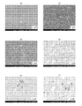
- FIG. 1 is a scanning electron microscope image of a STA-treated sample of the molded product obtained in Example 1 and Comparative Example 1
- FIGS. 1 (a) to 1 (c) are images of the molded product of Example 1.
- 1 (d) to 1 (f) are images of the molded product of Comparative Example 1.
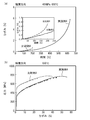
- Figure 2 is an image obtained by observing an enlarged Y 2 O 3 particles in the slow cooling heat treatment samples of 50 ° C. / h resulting molded article from 1180 ° C. to 1040 ° C. in Example 1 by a transmission electron microscope 3 (a) and 3 (b) are graphs showing the creep characteristics and the oxidation characteristics of the molded products obtained in Example 1 and Comparative Example 1, respectively.
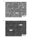
- FIG. 4 (a) and 4 (b) are scanning electron microscope images of the molded product obtained in Example 2 and Comparative Example 2, respectively.
- FIG. 5 is a graph showing the creep characteristics of the molded products obtained in Example 2 and Comparative Example 2.
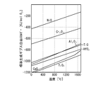
- FIG. 6 is a diagram showing an Ellingham diagram of each oxide.
- FIG. 7A is a diagram showing the creep characteristics of the orthogonal sample in Example 3, and
- FIG. 7B is a diagram showing the creep lifetime and creep ductility with respect to the Y content.
- FIG. 8A is a diagram showing the creep characteristics of the DA sample in the stacking direction in Example 3
- FIG. 8B is a diagram showing the creep life and creep ductility with respect to the Y content.
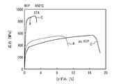
- FIG. 9 is a diagram showing a stress-strain curve in Example 3.
- FIG. 9 is a diagram showing a stress-strain curve in Example 3.
- FIG. 10A is a diagram showing creep characteristics in Example 4 and Comparative Example 4
- FIG. 10B is a diagram showing a stress-strain curve.
- 11 (a) and 11 (b) are diagrams showing creep characteristics in the orthogonal direction and the stacking direction after molding of Example 5 and Comparative Example 5.
- 12 (a) and 12 (b) are diagrams showing creep characteristics in the orthogonal direction and the stacking direction after the ST treatment of Example 5 and Comparative Example 5.
- FIG. 13 is a diagram showing element mapping using FE-EPMA in Example 6.
- FIG. 14 is a diagram showing element mapping using FE-EPMA in Comparative Example 6.
- FIG. 15 is a diagram showing an example of a method for manufacturing a heat-resistant alloy molded product.
- the heat-resistant alloy material of the present embodiment is a heat-resistant alloy material that can be laminated and formed by a laser or an electron beam, and is characterized by containing a main component metal and Y.
- a detailed description will be given.
- main component metal examples include Ni, Ti (tungsten), Al (aluminum), Fe (iron), Cr (chromium), Co (cobalt), Nb (niobium), Cu (copper), Mn (manganese), and Mo.
- Metallic elements such as (molybdenum), Ta (tantal), W (tungsten), Re (rhenium), Ru (rhenium), Hf (hafnium), Zr (zirconium), NiO, TiO, Al 2 O 3 , Cr 2 O
- metal oxides such as 3 and the like can be mentioned, and when used, they can be used alone or as a mixture of two or more kinds.
- Ni, Ti, Al, oxides thereof (NiO, TiO, Al 2 O 3 ) and a mixture thereof can be preferably used.
- these main component metals are preferably contained in the molded body as an oxidation-resistant film or an oxide dispersion-strengthening phase.
- the blending amount of each component in the main component metal is arbitrary depending on the composition, but for example, when Ni is the main component, it is preferable to blend Ni so as to contain 40% by mass or more in the entire alloy material.
- Al and Ti are the main components without using Ni, Al and Ti are blended so as to contain 50% by mass or more, and further 90% by mass or more in the total heat-resistant alloy material. Moreover, it is preferable to mix both so as to contain 5% by mass or more.
- each component used as the main component metal is preferably used in a particulate form (that is, powder).
- the average particle size is not particularly limited, and a desired particle size can be used. (Measurement method of average particle size)
- the average particle size can be obtained by visually measuring the particle size confirmed by a transmission electron microscope and taking the average. It is also possible to measure the distribution density of particles with a scanning electron microscope reflected electron image and obtain the average.
- Y ⁇ Y (yttrium)>
- Y those having a purity of 99.9% or more can be preferably used, and a commercially available metal Y can be used as an additive element without particular limitation as long as it satisfies this purity.
- Y is preferably in the form of Y 2 O 3 particles in combination with O, and the average particle size thereof is preferably 10 to 200 nm, more preferably 50 to 150 nm. Further, the average particle size at this time can be obtained in the same manner as in the above method.
- the additive manufacturing method using metal is a method in which metal powder is placed on a flat surface, laser irradiation is performed only on the necessary parts, and the metal powder is melted and solidified. At this time, there is a risk that the residual oxygen on the powder surface will dissolve and remain in the molded product as it is, and the characteristics of the sintered material will be deteriorated. Further, oxygen has a problem that it combines with Al which is a strengthening element to form alumina and consumes Al to deteriorate the high temperature strength and oxidation resistance of the alloy. In this respect, Y (yttrium) binds to oxygen cheaper than Al and forms a stable oxide (Y 2 O 3). Therefore, in the additive manufacturing method using a laser in which oxygen is inevitably mixed, the heat resistance and oxidation resistance of the obtained molded product can be improved by containing Y as an essential component.
- Y 2 O 3 which is an oxide of Y, contributes to high temperature strengthening as an oxide.
- yttria which is an oxide of Y
- the mechanical alloying method using yttria particles is extremely costly and it is impossible to form a material having a complicated shape. It was applied only for extremely limited applications.
- the selective laser melting method it is possible to form a complex-shaped material in which yttria particles, which are compounds of Y, are uniformly finely dispersed at a density described later due to the presence of solid solution oxygen.
- the amount of oxygen is as low as 20 ppm or less, so when Y is added, Y becomes oxygen. It combines with other alloying elements to form a harmful TCP (Topologically Close Packed) phase (see Non-Patent Document 1). Further, even in a polycrystalline alloy, Y hardly binds to oxygen, segregates and mainly binds to an alloy element to form a harmful compound, and the formation is non-uniform and an oxide of Y is formed throughout the molded product. No (Non-Patent Document 2). However, by forming an alloy powder material containing Y as an additive element in advance as in the present embodiment into a molded body by a layered manufacturing method using a laser, an oxide of Y can be uniformly and finely produced.
- ⁇ Mixing ratio> As for the blending ratio of the main component metal and Y, it is preferable to blend Y 2 O 3 oxide as Y 2 O 3 oxide in a molded product in which the blending ratio of Y is obtained so that Y is 2 atoms with respect to 3 atoms of mixed oxygen. Specifically, it is preferably adjusted to be 0.005% by mass or more and less than 1.0% by mass in the entire alloy material, and more preferably 0.01 to 0.5% by mass.
- the blending ratio of Y is 0.01% by mass or more and less than 1.0% by mass in the entire alloy material. It is preferably adjusted to 0.05 to 0.7% by mass, more preferably 0.1 to 0.5% by mass, and most preferably 0.1 to 0.5% by mass.
- the heat-resistant alloy material can be appropriately mixed with the additive elements usually used in this type of heat-resistant alloy material.
- the additive element include C (carbon), Si (silicon), B (boron), Ta, Re, Ru, Hf, Zr and the like.
- Hf and Zr form more stable oxides than Al and Ti, and thus have the same effect as Y.
- the heat-resistant alloy material of the present embodiment can be used by mixing the above-mentioned main component metal and Y by a known method.
- a heat-resistant alloy powder heat-resistant alloy material
- a method such as an atomization method in which a molten metal to which a Y element is added is sprayed, and this powder is heat-resistant for forming various molded bodies. It can be used as an alloy material.
- the heat-resistant alloy material of the present invention can be suitably used for the additive manufacturing method, and it is not that it cannot be used for other than the additive manufacturing method. It can also be applied to other methods.
- the molded product of the present embodiment is a molded product obtained by performing laminated molding with a laser or an electron beam using the powder of the heat-resistant alloy material of the present embodiment described above.
- the laser is usually carried out in a rare gas atmosphere such as Ar (argon), and the electron beam is usually carried out in a vacuum.
- the main component metal since it is formed by using the heat-resistant alloy material, the main component metal, is constituted by oxides and Y 2 O 3 of the main component metal and Y 2 O 3 is It is uniformly produced throughout the molded body and exists in a dispersed state.
- Such a component composition can be confirmed qualitatively as shown in Examples described later, but cannot be accurately shown by quantitatively quantifying or the like. Therefore, it is appropriate to express it methodically as described above.
- Y 2 O 3 particles and Y particles preferably are finely dispersed in 30 / [mu] m 2 or more densities.
- the manufacturing method of the molded body of the present embodiment will be described in detail.
- a predetermined portion of the laminated molding apparatus is used.
- the method used in ordinary powder mixing can be used without particular limitation.
- the laminated modeling apparatus may be any apparatus capable of melting and solidifying powder by laser irradiation without particular limitation.
- the laser to be used include a high-power Yb fiber laser and the like.
- the predetermined location depends on the device and means a location where laser irradiation is possible in the device to be used.
- the predetermined thickness is arbitrary depending on the output of the laser, but it is preferably 20 to 50 ⁇ m from the viewpoint of performing melt solidification to the extent that a desired effect is obtained.
- the laser irradiation conditions in the irradiation step are preferably such that the output is 100 to 400 W and the scanning speed is 1 to 7 m / sec.
- the above repeating step will be performed until the molded product is completed.
- the preferred conditions for laser irradiation and lamination are as follows.
- Stack thickness 40 ⁇ m
- the removal step can be performed by using a generally known method for removing powder, for example, a sandblaster or the like without particular limitation.
- Example 1 is an example of an IN718 alloy as a Ni-based alloy.
- a powder of a heat-resistant alloy material was prepared with the composition shown in Table 1 below. The powder was prepared by using a normal gas atomization method. The metal powder and other additives used are Y, Ni, Fe, Cr, Co, Al, Nb, Cu, Mn, Ti, Mo, C, and B.
- a molded product was prepared from the heat-resistant alloy powder obtained by the gas atomization method. The molded product was produced by using a laminated molding apparatus that irradiates the powder with a laser. The thickness of the molded body is a block block having a thickness of 45 mm.
- the molded product was subjected to solution treatment and aging (STA).
- STA solution treatment and aging
- the treatment conditions are solution heat treatment at 980 ° C. for 1 hour, first stage aging heat treatment at 718 ° C. for 8 hours after air cooling, second stage aging heat treatment at 621 ° C. for 10 hours after cooling in a heat treatment furnace, and then air cooling. ..
- the cross section of the obtained molded product was observed using an SEM (Scanning Electron Microscope) and a TEM (Transmission Electron Microscope).
- Creep characteristics A creep test was conducted in which a stress of 550 MPa was applied at a temperature of 650 ° C. and the elongation with time was examined.
- Oxidation characteristics Oxidation test was performed at a temperature of 800 ° C. in the atmosphere. The mass increase of the molded product with respect to the oxidation time was measured using an electronic balance.
- Example 1 The heat-resistant alloy material was prepared in the same manner as in Example 1 except that Y was not added, and a molded product was prepared. The obtained molded product was subjected to SEM observation in the same manner as in Example 1 to measure creep characteristics and oxidation characteristics.
- Table 1 shows the elemental compositions of the heat-resistant alloy powders not found in Example 1 and Comparative Example 1.
- 1 (a) to 1 (f) are diagrams showing images of SEM observation of samples after STA treatment of the molded product in Example 1 and Comparative Example 1.
- 1 (a) to 1 (c) are SEM images of the first embodiment, and the magnification increases from FIG. 1 (a) to FIG. 1 (c).
- 1 (d) to 1 (f) are SEM images of Comparative Example 1, and the magnification increases from FIG. 1 (d) to FIG. 1 (f).
- the magnifications of FIGS. 1 (a) to 1 (c) and FIGS. 1 (d) to 1 (f) are substantially the same.
- FIG. 2 shows a TEM observation image of the molded product in Example 1, which is a TEM image after heat treatment in which the molded product is laminated and decooled from 1180 ° C. to 1040 ° C. at a cooling rate of 50 ° C./h (hours). is there.
- FIG. 3A is a diagram showing the creep characteristics of the STA-treated sample of the molded product in Example 1 and Comparative Example 1
- FIG. 3B is a diagram showing the oxidation characteristics.
- FIG. 3 (a) is a diagram showing strain with respect to time
- FIG. 3 (b) is a diagram showing mass gain with respect to time (Mass Gain).
- the dots are measurement points and the curve is an approximate curve.
- Example 2 As shown in FIG. 2, it can be seen that form a Y 2 O 3 particles having a clear contour by slow cooling heat treatment of 50 ° C. / h from 1180 ° C. to 1040 ° C..
- the rupture time indicating the creep life was 134 hours, and the strain at the rupture point indicating the creep ductility was 1.29%. is there.
- the creep lifetime is 396 hours and the creep ductility is 5.76%.
- FIG. 3B the mass increase due to oxidation is smaller in Example 1 than in Comparative Example 1.
- the creep life, creep ductility and oxidation resistance were significantly improved as compared with Comparative Example 1.
- Example 2 The powder of the heat-resistant alloy material having the composition shown in Table 1 obtained in Example 1 and Comparative Example 1 was vacuum-sealed in a stainless steel capsule and hot isostatic pressed for 4 hours under the conditions of a temperature of 1180 ° C. and a pressure of 175 MPa. Each of them was subjected to hot isostatic pressing (HIP) sintering to obtain a molded product. An SEM photograph was taken of the obtained molded product in the same manner as in Example 1, and the creep characteristics were measured.
- HIP hot isostatic pressing
- FIG. 4 (a) and 4 (b) are diagrams showing SEM images of the molded products in Example 2 and Comparative Example 2, respectively.
- FIG. 5 is a diagram showing the creep characteristics of the molded product in Example 2 and Comparative Example 2. As shown in FIG. 4A, in Example 2, a white Laves phase and carbides are observed at the old particle interface, but Al 2 O 3 is not observed. On the other hand, as shown in FIG. 4 (b), in Comparative Example 2, a white Laves phase and fine Al 2 O 3 are observed along the old particle interface. As shown in FIG. 5, in Comparative Example 2, the creep life is 20.4 hours and the creep ductility is 0.13%. In Example 2, the creep lifetime is 322.5 hours and the creep ductility is 0.68%. As described above, it can be seen that the creep characteristics of Example 2 are improved as compared with Comparative Example 2.
- the elongated and bright region in FIGS. 1 (d) to 1 (f) is the ⁇ phase (Ni 3 Nb).
- the dark punctate region is Al 2 O 3 .
- the reaction formula in which the ⁇ phase and the Al 2 O 3 phase are formed in the IN718 alloy is considered to be as follows. Ni 3 (Al, Ti) + O ⁇ Ni + Al 2 O 3 + TiO (reaction formula 1) 3Ni + Nb ⁇ Ni 3 Nb ( ⁇ phase) (Reaction equation 2)
- Example 1 As shown in FIGS. 1 (a) to 1 (c), the bright ⁇ phase is hardly observed. It is known from the elemental mapping of FE-EPMA (Field Emission Electron Probe Micro Analysis) that Y and O are mainly present in the gray region in FIG. 1 (c). Accordingly, the gray area is considered to be Y 2 O 3 phase.
- FE-EPMA Field Emission Electron Probe Micro Analysis
- Example 1 The reason why the creep characteristics and the oxidation resistance performance were improved in Example 1 is that the reaction of Reaction Scheme 1 was suppressed because Y was contained in Example 1, and Y was oxidized to generate Y 2 O 3 instead. it is conceivable that.
- FIG. 6 is a diagram showing an Ellingham diagram of each oxide and a diagram showing the standard Gibbs free energy with respect to temperature.
- Ni, Cr, Al relative to the oxide NiO, Cr 2 O 3, Al 2 O 3 and the standard Gibbs free energy of TiO of Ti, Ca, oxides of Hf and Y CaO, HfO
- the standard Gibbs free energy of 2 and Y 2 O 3 is low.
- the standard enthalpy of Gibbs free energy of Y 2 O 3 is the lowest. Therefore, O contained in the alloy is mainly used for oxidation of Y, and is not used for oxidation of Ni, Cr, Ti and Al.
- Example 1 it is considered that the formation of the ⁇ phase, which is a harmful phase, is suppressed, and the creep characteristics and the oxidation resistance performance are improved.
- Example 3 In the IN718 alloy, in order to investigate the appropriate content of Y with respect to the content of O, IN718 alloys having different contents of Y were prepared.
- the method for producing the molded body was the same as that in Example 1, and the molded body was formed by using the additive manufacturing method, and then the STA treatment was performed.
- M280 manufactured by EOS (Electro Optical Systems) was used as the laminated modeling apparatus.
- Table 2 is a table showing the elemental composition of the alloy powder in the samples A to E. Sample A is Comparative Example 1, Sample C is Example 1, and Samples B, D and E are Example 3. Sample B'is a molded product molded using Sample B. Min and Max are the minimum and maximum values of the alloy composition standard, respectively. Bal. Is Balance and shows the rest. The same applies to the table showing the elemental composition of the following examples. The Fe content was converted from the content of other elements.
- Y / O indicates the ratio of the mass-equivalent content of yttrium to the mass-equivalent content of oxygen.
- the theoretical value of Y / O in Y 2 O 3 is 3.9.
- Y / O is a theoretical value of 3.9 and all Y are Y 2 O 3 , most of the O in the alloy is consumed by Y 2 O 3.
- Y / O is 0.
- the Y / O is 5.2, which is almost a theoretical value.
- the Y / O is 10.0, which is about 3 times the theoretical value
- sample D of Example 3 the Y / O is 45.7, which is about 10 times the theoretical value.
- sample E of Example 3 although the Y content is large, the O content is also large, so the Y / O is 40.8, which is about 10 times the theoretical value.
- a sample was prepared for measuring the creep characteristics in the stacking direction of the additive manufacturing method and in the direction orthogonal to the stacking direction.
- a sample whose creep direction (direction in which stress is applied) is the stacking direction is a stacking direction sample, and a sample whose creep direction is orthogonal to the stacking direction is an orthogonal direction sample.
- FIG. 7 (a) is a diagram showing the creep characteristics of the sample in the stacking direction in Example 3
- FIG. 7 (b) is a diagram showing the creep life and creep ductility (strain at the rupture point) with respect to the Y content. As shown in FIGS. 7 (a) and 7 (b), the creep life becomes longer as the Y content increases. Sample C having a Y content of 0.0 mass and 7% has the largest creep ductility.
- FIG. 8A is a diagram showing the creep characteristics of the orthogonal sample in Example 3
- FIG. 8B is a diagram showing the creep life and creep ductility (strain at the rupture point) with respect to the Y content.
- the creep life and the creep ductility of the sample C having a Y content of 0.07% by mass are the largest.
- the creep life and creep ductility of sample C having a Y / O of 10 are the largest.
- the creep lifetime and creep ductility of sample B having a Y / O of 5.2 are not as large as those of sample C but larger than that of sample A of Comparative Example 1.
- the creep lifetime and creep ductility in the orthogonal direction and the creep ductility in the stacking direction of sample D having a Y / O of 45.7 are smaller than sample C but larger than sample A.
- Sample E has a Y content higher than that of Sample D, but Y / O is similar to that of Sample D.
- the creep life and creep ductility of sample E are not significantly different from those of sample D. Thus, it is considered that Y / O affects the creep characteristics rather than the Y content.
- a molded product was prepared by the HIP method using the powders of Samples A and C. As for the production conditions, a pressure of 175 MPa was applied for 4 hours at a temperature of 1180 ° C. The molded product produced by the HIP method was subjected to STA treatment. The stress-strain curve was measured at 650 ° C. for the samples after preparation by the HIP method and after STA treatment.
- FIG. 9 is a diagram showing a stress-strain curve in Example 3. The test was conducted at a tensile strain rate of 4.25 ⁇ 10 -4 seconds -1.
- as-HIP is a sample immediately after preparation by HIP
- STA is a sample after STA treatment.
- sample C has a lower proof stress than sample A but has higher ductility.
- the ductility of both samples A and C becomes small.
- Sample C has a high breaking stress and a large ductility.
- the sample C having a Y / O of 10 has a higher ductility than the sample A of the comparative example 1.
- Example 4 is an example of IN625 (INCONEL (registered trademark) 625 alloy (hereinafter referred to as IN625)).
- An alloy powder was produced using the atomizing method, and a molded product was produced using the additive manufacturing method. M280 manufactured by EOS Co., Ltd. was used as the laminated modeling apparatus. After that, STA treatment was performed.
- the STA conditions are 1 hour heat treatment at 1120 ° C (sample for creep characteristics in FIG. 10 (a)) or 980 ° C (sample for stress-strain curve in FIG. 10 (b)), 8 hours treatment at 718 ° C after air cooling. After cooling in a heat treatment furnace, heat treatment is performed at 621 ° C. for 10 hours, followed by air cooling.
- Table 3 is a table showing the elemental composition in the alloy powder.
- the Y / O is 2.53. Comparative Example 4 does not contain Y.
- Example 4 the creep characteristics in the stacking direction were measured.
- the measurement conditions are a temperature of 650 ° C. and a stress of 550 MPa.
- the stress-strain curve was measured.
- the measurement temperature is 650 ° C.
- FIG. 10A shows the creep characteristics in Example 4 and Comparative Example 4
- FIG. 10B is a diagram showing a stress-strain curve.
- Example 4 has a larger creep life and creep ductility than Comparative Example 4.
- the proof stress is lower than that in Comparative Example 4, but the ductility is improved. It is considered that the proof stress decreased in Example 4 because the size and amount of the ⁇ phase decreased.
- Example 4 has improved creep characteristics and ductility as compared with Comparative Example 4.
- Example 5 is an example of Hastelloy® X, a Ni-based alloy containing Cr and Mo. An alloy powder was produced using the atomizing method, and a molded product was produced using the additive manufacturing method. M290 manufactured by EOS Co., Ltd. was used as the laminated modeling apparatus. As a heat treatment, a solution treatment (ST) was performed at a temperature of 1177 ° C. for 2 hours.
- Table 4 is a table showing the elemental composition in the alloy powder.
- the Y / O is 3.9. Comparative Example 5 does not contain Y. The Ni content was converted from the content of other elements.
- Example 5 the creep characteristics of the samples after molding and after ST treatment were measured.
- the measurement conditions are a temperature of 900 ° C. and a stress of 80 MPa.
- EDS Electronic Dispersive X-ray Spectroscopy
- 11 (a) and 11 (b) are diagrams showing creep characteristics in the stacking direction and the orthogonal direction after molding of Example 5 and Comparative Example 5, respectively.
- 12 (a) and 12 (b) are diagrams showing creep characteristics in the stacking direction and the orthogonal direction after the ST treatment of Example 5 and Comparative Example 5, respectively.
- Example 5 As shown in FIGS. 11 (a) to 12 (b), the creep life of Example 5 is higher than that of Comparative Example 5 in both the post-mold production and the ST treatment, and in both the stacking direction and the orthogonal direction. Is long and has a large creep ductility. As described above, the creep characteristics of Example 5 are improved as compared with Comparative Example 5. As in Example 5, the creep characteristics are improved by adding Y even in the solid solution reinforced alloy containing no Nb, Al and Ti.
- Example 6 is an example of the TiAl4822 alloy as the TiAl alloy.
- An alloy powder was prepared using the atomizing method, and a molded product was prepared using the discharge plasma sintering (SPS) method.
- SPS method is a method of sintering a work piece in a vacuum by mechanical pressurization and pulse energization heating. Then heat treatment was performed. Each condition is as follows.
- the pressing force in the SPS method was 50 MPa, and the temperature was kept at 1075 ° C. for 10 minutes.
- As the heat treatment after heat treatment at a temperature of 1205 ° C. for 5 hours in vacuum, homogenization heat treatment for furnace cooling was performed.
- Table 5 is a table showing the elemental composition in the alloy powder.
- the Y / O is 2.63.
- Y is not contained. The Ti content was converted from the content of other elements.
- FIG. 13 is a diagram showing element mapping using FE-EPMA in Example 6
- FIG. 14 is a diagram showing element mapping using FE-EPMA in Comparative Example 6.
- COMPO is an SEM reflected electron composition image.
- a coarse white phase is observed in the SEM image.
- This phase contains a large amount of Ti and O, and is a segregated phase of Ti and O.
- the segregated phase of Ti and O was not observed.
- the oxygen concentration can be reduced by producing alloys using the Cast & Wrought (C & W) method, the casting method and the forging method. With these methods, it is difficult to produce a molded product having a complicated shape.
- Laminate molding methods such as SLM (Selective Laser Melting) method using laser light and EBM (Electron Beam Melting) method using electron beam, hot isostatic pressing (HIP) method, powder bed melt bonding (PBF: A molded alloy is formed using the Powder Bed fusion) method and the Direct Energy Deposition (DED) method. This makes it possible to manufacture a molded product having a complicated shape.
- These methods form moldings from alloy powders. Since the alloy powder has a large surface area, oxygen is easily taken into the alloy. As a result, a large amount of oxygen is contained in the molded body formed from the alloy powder.
- Molds other than those molded from heat-resistant alloy powder may also contain a large amount of oxygen. Such a heat-resistant alloy molded product deteriorates in performance such as creep characteristics.
- heat-resistant alloys containing at least one element of Al, Ti, Ni, Cr and Mo have a harmful phase formed by oxidation of these elements and the performance of the alloy deteriorates. .. Therefore, as shown in FIG. 6, Y, which has a lower standard enthalpy of formation Gibbs free energy of oxide than Al, Ti, Ni, Cr and Mo, is added to the alloy.
- the ratio Y / O of the reduced mass-equivalent content of Y to the mass-equivalent content of O in the stoichiometric composition ratio of yttria (Y 2 O 3) is 3.9. Therefore, the Y / O is set to 0.5 or more and 100 or less. Oxidation of at least one of Al, Ti, Ni, Cr and Mo can be suppressed. Therefore, it is possible to improve the performance such as creep characteristics of the heat-resistant alloy.
- the Y / O is preferably 1.0 or more, more preferably 2.6 or more, and even more preferably 3.9 or more. Further, from the viewpoint of suppressing excess Y, the Y / O is preferably 71 or less, more preferably 40 or less, and further preferably 10 or less.
- the Ni content is 40.0% by mass or more, for example, 50.0% by mass or more.
- the O content in the casting forging method, the casting method, and the alloy produced by the forging method is, for example, 5 ppm to 20 ppm.
- the O content in the alloy powder and the molded product molded from the alloy powder is, for example, 50 ppm to 200 ppm.
- the O content in the alloy is 0.002% by mass (20 ppm) or more, the performance is deteriorated due to the oxide as compared with the casting forging method, the casting method and the alloy produced by the forging method. Therefore, it is preferable to add Y.
- the content of O in the alloy is preferably 0.1% by mass (1000 ppm) or less, and more preferably 0.05% by mass (500 ppm) or less so as not to deteriorate the performance of the alloy.
- Ni-based alloy when the content of at least one element of Al, Ti, Cr and Mo is 0.01% by mass or more, at least one element of Al, Ti, Cr and Mo is oxidized and the performance of the alloy is obtained. Deteriorates. Therefore, it is preferable to add Y.
- the content of at least one element of Al, Ti, Cr and Mo is 0.1% by mass or more, at least one element of Al, Ti, Cr and Mo is oxidized, and the performance of the alloy is further deteriorated. Therefore, it is preferable to add Y.
- the content of at least one element of Al and Ti in the alloy is 0.01% by mass or more and 1.0% by mass or less, and the content of Nb is 1.0% by mass or more and 10.0% by mass or less.
- Ni content is 50.0% by mass or more and 55.0% by mass or less
- Cr content is 17.0% by mass or more and 21.0% by mass or less
- Fe content is 11.0% by mass or more and 25.0% by mass or less
- Mo content is 2.8% by mass or more and 3.3% by mass or less
- the content of Nb is 4.75% by mass or more and 5.50% by mass or less.
- Al content is 0.20% by mass or more and 0.80% by mass or less
- the Ti content is 0.65% by mass or more and 1.15% by mass or less.
- Ni content is 58.0% by mass or more
- Cr content is 20.0% by mass or more and 23.0% by mass or less
- Mo content is 8.0% by mass or more and 10.0% by mass or less
- the content of Nb is 3.15% by mass or more and 4.15% by mass or less.
- Y it is preferable to add Y to the Ni-based alloy when the content of at least one of Cr and Mo is 1% by mass or more, as in Hastelloy® X alloy in Example 5.
- the content of at least one element of Cr and Mo is more preferably 5% by mass or more.
- Hastelloy® X alloy the contents of the main elements are as shown in Table 4.
- Ni content is 41.0% by mass or more and 54.0% by mass or less
- Cr content is 20.5% by mass or more and 23.0% by mass or less
- Mo content is 8.0% by mass or more and 10.0% by mass or less
- Fe content is 17.0% by mass or more and 20.0% by mass or less
- W content is 0.2% by mass or more and 1.0% by mass or less
- the content of Co is 0.5% by mass or more and 2.5% by mass or less.
- the Ti content is 50% by mass or more, for example, 60% by mass or more.
- the Ti content is 30% by mass or more, for example, 50% by mass or more.
- the Al content is 3% by mass or more, for example, 10% by mass or more, and for example, 30% by mass or more.
- the O content in the casting forging method, the casting method and the alloy produced by the forging method is, for example, 250 ppm to 500 ppm.
- the O content in the alloy powder and the molded product molded from the alloy powder is, for example, 700 ppm to 1100 ppm.
- the O content in the alloy is 0.05% by mass (500 ppm) or more, the performance is deteriorated due to the oxide as compared with the casting forging method, the casting method and the alloy produced by the forging method. Therefore, it is preferable to add Y.
- the O content in the alloy is 0.07% by mass (700 ppm) or more, the performance of the alloy is further deteriorated. Therefore, it is preferable to add Y to the alloy.
- the content of O in the alloy is preferably 1.0% by mass (10000 ppm) or less, more preferably 0.2% by mass (2000 ppm) or less so as not to deteriorate the performance of the alloy.
- the content of the main elements is as shown in Table 5.
- the Ti content is 56.0% by mass or more and 64.0% by mass or less.
- Al content is 33.0% by mass or more and 35.0% by mass or less, Cr content is 2.2% by mass or more and 2.7% by mass or less,
- the Nb content is 4.5% by mass or more and 5.1% by mass or less. Is.
- Y may be added to the Ti64 alloy.
- the content of the main elements is The Ti content is bal, which is 88.0% by mass or more and 91.0% by mass or less.
- Al content is 5.5% by mass or more and 6.75% by mass or less,
- the V content is 3.5% by mass or more and 4.5% by mass or less, Is.
- FIG. 15 is a diagram showing an example of a method for manufacturing a heat-resistant alloy molded product.
- an alloy powder is prepared (step S10).
- the alloy powder is produced, for example, by using an atomizing method.
- an alloy molded product is produced by molding the alloy powder (step S12).
- a hot dowel pressure processing method for example, a hot dowel pressure processing method, a powder bed melt bonding method and a directed energy deposition method can be used.
- the molded product is heat-treated (step S14).
- As the heat treatment for example, solution aging treatment and direct aging treatment (DA: Direct Aging) can be used.
- DA Direct Aging
- the heat-resistant alloy may be the heat-resistant alloy powder produced in step S10, or the heat-resistant alloy molded body produced in steps S12 and S14.
- the heat-resistant alloy of the present embodiment is useful in fields such as aircraft engines, rocket engines, industrial gas turbines, and automobile engines because its high-temperature strength characteristics and oxidation resistance are improved.
Abstract
This heat-resistant alloy contains: at least one element from among Al, Ti, Ni, Cr, and Mo; O; and Y, the ratio of the Y content in terms of mass to the O content in terms of mass being 5-100 inclusive.
Description
本発明は、耐熱合金、耐熱合金粉末、耐熱合金成形体およびその製造方法に関する。
The present invention relates to a heat-resistant alloy, a heat-resistant alloy powder, a heat-resistant alloy molded product, and a method for producing the same.
航空機のエンジン等に耐熱合金が用いられている。耐熱合金の成形体の形成方法として積層造形法が知られている(例えば特許文献1)。柱状晶を有する合金における結晶粒内および結晶粒界にY(イットリウム)等を有するセラミックス粒子を分散させることが知られている(例えば特許文献2)。Ni(ニッケル)基合金に、Yを添加することが知られている(例えば非特許文献1および2)。
Heat-resistant alloys are used in aircraft engines, etc. A layered manufacturing method is known as a method for forming a heat-resistant alloy molded body (for example, Patent Document 1). It is known that ceramic particles having Y (yttrium) or the like are dispersed in crystal grains and at grain boundaries in an alloy having columnar crystals (for example, Patent Document 2). It is known to add Y to a Ni (nickel) -based alloy (for example, Non-Patent Documents 1 and 2).
例えば積層造形法を用い形成した合金の成形体にはO(酸素)が多く含まれる。酸素が多く含まれる合金では合金の性能が劣化することがある。特許文献2、非特許文献1および2には、合金にYを添加することが記載されているが、Oとの関係については記載されていない。
For example, an alloy molded body formed by using the additive manufacturing method contains a large amount of O (oxygen). Alloys containing a large amount of oxygen may deteriorate the performance of the alloy. Patent Document 2 and Non-Patent Documents 1 and 2 describe that Y is added to the alloy, but do not describe the relationship with O.
本発明は上記課題に鑑みなされたものであり、酸素とイットリウムとの比を特定することにより合金の性能を向上させることを目的とする。
The present invention has been made in view of the above problems, and an object of the present invention is to improve the performance of an alloy by specifying the ratio of oxygen and yttrium.
本発明は、Al、Ti、Ni、CrおよびMoの少なくとも1つの元素、OおよびYを含有し、Oの質量換算の含有量に対するYの質量換算の含有量の比は0.5以上かつ100以下である耐熱合金である。
The present invention contains at least one element of Al, Ti, Ni, Cr and Mo, O and Y, and the ratio of the reduced mass-equivalent content of Y to the mass-equivalent content of O is 0.5 or more and 100. It is the following heat-resistant alloy.
上記構成において、Niの含有量は40.0質量%以上であり、Oの含有量は0.002質量%以上かつ0.1質量%以下である構成とすることができる。
In the above configuration, the Ni content can be 40.0% by mass or more, and the O content can be 0.002% by mass or more and 0.1% by mass or less.
上記構成において、Niの含有量は50.0質量%以上かつ55.0質量%以下、Crの含有量は17.0質量%以上かつ21.0質量%以下、Feの含有量は11.0質量%以上かつ25.0質量%以下、Moの含有量は2.8質量%以上かつ3.3質量%以下、Nbの含有量は4.75質量%以上かつ5.50質量%以下、Alの含有量は0.20質量%以上かつ0.80質量%以下、Tiの含有量は0.65質量%以上かつ1.15質量%以下、およびOの含有量は0.002質量%以上かつ0.1質量%以下である構成とすることができる。
In the above configuration, the Ni content is 50.0% by mass or more and 55.0% by mass or less, the Cr content is 17.0% by mass or more and 21.0% by mass or less, and the Fe content is 11.0. Mass% or more and 25.0 mass% or less, Mo content is 2.8 mass% or more and 3.3 mass% or less, Nb content is 4.75 mass% or more and 5.50 mass% or less, Al The content of is 0.20% by mass or more and 0.80% by mass or less, the content of Ti is 0.65% by mass or more and 1.15% by mass or less, and the content of O is 0.002% by mass or more and 0.002% by mass or less. It can be configured to be 0.1% by mass or less.
上記構成において、Niの含有量は58.0質量%以上、Crの含有量は20.0質量%以上かつ23.0質量%以下、Moの含有量は8.0質量%以上かつ10.0質量%以下、Nbの含有量は3.15質量%以上かつ4.15質量%以下、およびOの含有量は0.002質量%以上かつ0.1質量%以下である構成とすることができる。
In the above configuration, the Ni content is 58.0% by mass or more, the Cr content is 20.0% by mass or more and 23.0% by mass or less, and the Mo content is 8.0% by mass or more and 10.0% by mass. The composition may be such that the content of Nb is 3.15% by mass or more and 4.15% by mass or less, and the content of O is 0.002% by mass or more and 0.1% by mass or less. ..
上記構成において、Niの含有量は41.0質量%以上かつ54.0質量%以下、Crの含有量は20.5質量%以上かつ23.0質量%以下、Moの含有量は8.0質量%以上かつ10.0質量%以下、Feの含有量は17.0質量%以上かつ20.0質量%以下、Wの含有量は0.2質量%以上かつ1.0質量%以下、Coの含有量は0.5質量%以上かつ2.5質量%以下、およびOの含有量は0.002質量%以上かつ0.1質量%以下である構成とすることができる。
In the above configuration, the Ni content is 41.0% by mass or more and 54.0% by mass or less, the Cr content is 20.5% by mass or more and 23.0% by mass or less, and the Mo content is 8.0. Mass% or more and 10.0% by mass or less, Fe content is 17.0% by mass or more and 20.0% by mass or less, W content is 0.2% by mass or more and 1.0% by mass or less, Co. The content of is 0.5% by mass or more and 2.5% by mass or less, and the content of O is 0.002% by mass or more and 0.1% by mass or less.
上記構成において、Tiの含有量は50質量%以上、またはTiの含有量は30質量%以上かつAlの含有量は3質量%以上であり、Oの含有量は0.05質量%以上かつ1.0質量%以下である構成とすることができる。
In the above configuration, the Ti content is 50% by mass or more, the Ti content is 30% by mass or more and the Al content is 3% by mass or more, and the O content is 0.05% by mass or more and 1 It can be configured to be 0.0% by mass or less.
上記構成において、Tiの含有量は56.0質量%以上かつ64.0質量%以下、Alの含有量は33.0質量%以上かつ35.0質量%以下、Crの含有量は2.2質量%以上かつ2.7質量%以下、Nbの含有量は4.5質量%以上かつ5.1質量%以下、およびOの含有量は0.06質量%以上かつ1.0質量%以下である構成とすることができる。
In the above configuration, the Ti content is 56.0% by mass or more and 64.0% by mass or less, the Al content is 33.0% by mass or more and 35.0% by mass or less, and the Cr content is 2.2. The content of Nb is 4.5% by mass or more and 5.1% by mass or less, and the content of O is 0.06% by mass or more and 1.0% by mass or less. It can have a certain configuration.
上記構成において、Oの質量換算の含有量に対するYの質量換算の含有量の比は2.0以上かつ43以下である構成とすることができる。
In the above configuration, the ratio of the mass-converted content of Y to the mass-converted content of Y can be 2.0 or more and 43 or less.
上記構成において、Yの少なくとも一部はイットリアとして含有する構成とすることができる。
In the above configuration, at least a part of Y can be contained as yttria.
本発明は、上記耐熱合金を含む耐熱合金粉末である。
The present invention is a heat-resistant alloy powder containing the above heat-resistant alloy.
本発明は、上記耐熱合金を含む耐熱合金成形体である。
The present invention is a heat-resistant alloy molded product containing the above heat-resistant alloy.
本発明は、上記耐熱合金粉末を成形することにより成形体を形成する工程を含む耐熱合金成形体の製造方法である。
The present invention is a method for producing a heat-resistant alloy molded product, which comprises a step of forming a molded product by molding the heat-resistant alloy powder.
本発明によれば、合金の性能を向上させることができる。
According to the present invention, the performance of the alloy can be improved.
以下、本発明の実施形態をさらに詳細に説明する。本実施形態の耐熱合金材料は、レーザー又は電子ビームで積層造形可能な耐熱合金材料であって、主成分金属とYとを含有することを特徴とする。以下、詳細に説明する。
Hereinafter, embodiments of the present invention will be described in more detail. The heat-resistant alloy material of the present embodiment is a heat-resistant alloy material that can be laminated and formed by a laser or an electron beam, and is characterized by containing a main component metal and Y. Hereinafter, a detailed description will be given.
<主成分金属>
上記主成分金属としては、Ni、Ti(チタン)、Al(アルミニウム)、Fe(鉄)、Cr(クロム)、Co(コバルト)、Nb(ニオブ)、Cu(銅)、Mn(マンガン)、Mo(モリブデン)、Ta(タンタル)、W(タングステン)、Re(レニウム)、Ru(ルテニウム)、Hf(ハフニウム)、Zr(ジルコニウム)等の金属元素、NiO、TiO、Al2O3、Cr2O3等の金属酸化物等を挙げることができ、使用に際してはそれぞれ単独もしくは2種以上の混合物として用いることができる。本実施形態においては、特に、上記主成分金属が、Ni、Ti、Al及びこれらの酸化物(NiO、TiO、Al2O3)並びにこれらの混合物を好ましく用いることができる。 <Main component metal>
Examples of the main component metal include Ni, Ti (tungsten), Al (aluminum), Fe (iron), Cr (chromium), Co (cobalt), Nb (niobium), Cu (copper), Mn (manganese), and Mo. Metallic elements such as (molybdenum), Ta (tantal), W (tungsten), Re (rhenium), Ru (rhenium), Hf (hafnium), Zr (zirconium), NiO, TiO, Al 2 O 3 , Cr 2 O Examples of metal oxides such as 3 and the like can be mentioned, and when used, they can be used alone or as a mixture of two or more kinds. In the present embodiment, in particular, as the main component metal, Ni, Ti, Al, oxides thereof (NiO, TiO, Al 2 O 3 ) and a mixture thereof can be preferably used.
本実施形態の耐熱合金材料を用いてなる成形体において、これらの主成分金属、特に金属酸化物は、耐酸化皮膜または酸化物分散強化相として成形体に含有されるのが好ましい。主成分金属における各成分の配合量は、組成により任意であるが、例えばNiを主成分とする場合には、Niを合金材料全体において40質量%以上含有するように配合するのが好ましい。また、Niを用いずにAlとTiとを主成分とする場合には、AlとTiとを合計で耐熱合金材料全体において50質量%以上、更には90質量%以上含有するように配合し、且つ両者共に5質量%以上含有するように配合するのが好ましい。
In the molded body using the heat-resistant alloy material of the present embodiment, these main component metals, particularly metal oxides, are preferably contained in the molded body as an oxidation-resistant film or an oxide dispersion-strengthening phase. The blending amount of each component in the main component metal is arbitrary depending on the composition, but for example, when Ni is the main component, it is preferable to blend Ni so as to contain 40% by mass or more in the entire alloy material. When Al and Ti are the main components without using Ni, Al and Ti are blended so as to contain 50% by mass or more, and further 90% by mass or more in the total heat-resistant alloy material. Moreover, it is preferable to mix both so as to contain 5% by mass or more.
また、上記主成分金属として用いる各成分は粒子状の形態(すなわち粉末)にて使用に供するのが好ましい。その平均粒子径は特に制限されず、所望の粒子径にて使用することができる。
(平均粒子径の測定法)
上記平均粒子径は、透過電子顕微鏡で確認される粒子径を目視により計測し、平均をとることで求めることができる。また、走査電子顕微鏡反射電子像で粒子の分布密度を計測して、平均を求めることもできる。 Further, each component used as the main component metal is preferably used in a particulate form (that is, powder). The average particle size is not particularly limited, and a desired particle size can be used.
(Measurement method of average particle size)
The average particle size can be obtained by visually measuring the particle size confirmed by a transmission electron microscope and taking the average. It is also possible to measure the distribution density of particles with a scanning electron microscope reflected electron image and obtain the average.
<Y(イットリウム)>
Yとしては、純度99.9%以上のものを好ましく用いることができ、この純度を満足するものであれば市販の金属Yを添加元素として特に制限なく用いることができる。また、Yは、Oと結びついてY2O3粒子状であるのが好ましく、その平均粒子径は、好ましくは、10~200nmであるのが好ましく、50~150nmであるのが更に好ましい。また、この際の平均粒子径は、上記の方法と同様にして求めることができる。 <Y (yttrium)>
As Y, those having a purity of 99.9% or more can be preferably used, and a commercially available metal Y can be used as an additive element without particular limitation as long as it satisfies this purity. Further, Y is preferably in the form of Y 2 O 3 particles in combination with O, and the average particle size thereof is preferably 10 to 200 nm, more preferably 50 to 150 nm. Further, the average particle size at this time can be obtained in the same manner as in the above method.
金属を用いた積層造形法は、金属粉末を平面上に載置し、その必要箇所だけにレーザー照射を行い、溶融凝固させることにより造形する方法である。この際、粉末表面の酸素の残存がそのまま造形品に固溶および残存して焼結材の特性を劣化させてしまうリスクがある。また、酸素は、強化元素であるAlと結合してアルミナを形成して、Alを消耗して合金の高温強度や耐酸化性を劣化させるという問題もある。この点、Y(イットリウム)はAlよりも酸素と結びつき安く、安定な酸化物(Y2O3)を形成する。このため、酸素の混入が不可避のレーザーを用いた積層造形法において、Yを必須成分として含有することにより、得られる成形体の耐熱性や耐酸化性を向上させることができる。
The additive manufacturing method using metal is a method in which metal powder is placed on a flat surface, laser irradiation is performed only on the necessary parts, and the metal powder is melted and solidified. At this time, there is a risk that the residual oxygen on the powder surface will dissolve and remain in the molded product as it is, and the characteristics of the sintered material will be deteriorated. Further, oxygen has a problem that it combines with Al which is a strengthening element to form alumina and consumes Al to deteriorate the high temperature strength and oxidation resistance of the alloy. In this respect, Y (yttrium) binds to oxygen cheaper than Al and forms a stable oxide (Y 2 O 3). Therefore, in the additive manufacturing method using a laser in which oxygen is inevitably mixed, the heat resistance and oxidation resistance of the obtained molded product can be improved by containing Y as an essential component.
また、Yの酸化物であるY2O3(イットリア)は、酸化物として高温強化に寄与する。しかし、イットリア粒子を使用するメカニカルアロイング法(固体の状態で機械的に混合して合金を作る方法)は、コストが極めて高いことや、複雑形状の素材を成形することが不可能であり、極めて限定的な用途のみの適用となっていた。しかし、選択的レーザー溶融法では、固溶酸素の存在によりYの化合物であるイットリア粒子が後述する密度で均一に微細分散させた複雑形状素材を成形可能である。
In addition, Y 2 O 3 (yttria), which is an oxide of Y, contributes to high temperature strengthening as an oxide. However, the mechanical alloying method using yttria particles (a method of mechanically mixing in a solid state to form an alloy) is extremely costly and it is impossible to form a material having a complicated shape. It was applied only for extremely limited applications. However, in the selective laser melting method, it is possible to form a complex-shaped material in which yttria particles, which are compounds of Y, are uniformly finely dispersed at a density described later due to the presence of solid solution oxygen.
また、合金粉末を用いる積層造形法以外の特殊溶解精錬プロセスを経た鋳造法(鋳造後鍛造する鍛造法も含む)においては、酸素量が20ppm以下と低いために、Yを添加すると、Yは酸素と結びつかずに、他の合金元素と結合して有害なTCP(Topologically Close Packed)相を形成する(非特許文献1参照)。また、多結晶合金においてもYはほとんど酸素と結合しないで、偏析して主として合金元素と結合して有害な化合物を形成し、生成が不均一で成形体全体に亘ってYの酸化物が生成しない(非特許文献2)。しかし、本実施形態のようにYを予め添加元素とした合金粉末材料を、レーザーを用いる積層造形法によって成形体とすることで、Yの酸化物を均一に微細生成させることができる。
In addition, in the casting method (including the forging method for forging after casting) that has undergone a special melt refining process other than the laminated molding method using alloy powder, the amount of oxygen is as low as 20 ppm or less, so when Y is added, Y becomes oxygen. It combines with other alloying elements to form a harmful TCP (Topologically Close Packed) phase (see Non-Patent Document 1). Further, even in a polycrystalline alloy, Y hardly binds to oxygen, segregates and mainly binds to an alloy element to form a harmful compound, and the formation is non-uniform and an oxide of Y is formed throughout the molded product. No (Non-Patent Document 2). However, by forming an alloy powder material containing Y as an additive element in advance as in the present embodiment into a molded body by a layered manufacturing method using a laser, an oxide of Y can be uniformly and finely produced.
<配合割合>
上記主成分金属とYとの配合割合は、Yの配合割合が得られる成形体においてY2O3酸化物として、混入酸素3原子に対しYが2原子となるように配合するのが好ましい。具体的には、合金材料全体中0.005質量%以上、1.0質量%未満となるように調整するのが好ましく、0.01~0.5質量%とするのが更に好ましい。 <Mixing ratio>
As for the blending ratio of the main component metal and Y, it is preferable to blend Y 2 O 3 oxide as Y 2O 3 oxide in a molded product in which the blending ratio of Y is obtained so that Y is 2 atoms with respect to 3 atoms of mixed oxygen. Specifically, it is preferably adjusted to be 0.005% by mass or more and less than 1.0% by mass in the entire alloy material, and more preferably 0.01 to 0.5% by mass.
上記主成分金属とYとの配合割合は、Yの配合割合が得られる成形体においてY2O3酸化物として、混入酸素3原子に対しYが2原子となるように配合するのが好ましい。具体的には、合金材料全体中0.005質量%以上、1.0質量%未満となるように調整するのが好ましく、0.01~0.5質量%とするのが更に好ましい。 <Mixing ratio>
As for the blending ratio of the main component metal and Y, it is preferable to blend Y 2 O 3 oxide as Y 2
また、上記主成分金属がTiおよびAlとなる、Ti合金およびTiAl合金である場合には、Yの配合割合が、合金材料全体中0.01質量%以上、1.0質量%未満となるように調整するのが好ましく、0.05~0.7質量%とするのが更に好ましく、0.1~0.5質量%とするのが最も好ましい。
Further, in the case of Ti alloy and TiAl alloy in which the main component metals are Ti and Al, the blending ratio of Y is 0.01% by mass or more and less than 1.0% by mass in the entire alloy material. It is preferably adjusted to 0.05 to 0.7% by mass, more preferably 0.1 to 0.5% by mass, and most preferably 0.1 to 0.5% by mass.
下限未満であると十分に性能の向上が得られず、0.5質量%以上添加すると、最終的に得られる成形物に劣化が見られるので、上記範囲内とするのが好ましい。このように添加量によって得られる効果に差が生じるのは、積層造形の場合、真空中で造形しても微量な酸素量を抑えるのが難しく、積層造形するに際して不要な酸化物が生成して耐熱性や耐酸化性を低下させるが、Yを上述の添加量で含有することにより、Y2O3が他の金属元素の酸化物よりも早く生成し、Ti合金およびTiAl合金では固溶酸素量を下げ、組織を安定化し基材の脆化を防ぎ、INCONEL(登録商標)718合金(以下IN718)では有害なδ(デルタ)相の量と大きさが減少しり、結果各特性を高くすることができる。また、酸素の量を考慮してもYの添加量を上述の範囲内とすることで添加したYが、合金元素と化合物を生成するのを抑制して、効果的にOをY2O3に転換することができる。
If it is less than the lower limit, the performance cannot be sufficiently improved, and if 0.5% by mass or more is added, deterioration is observed in the finally obtained molded product. The difference in the effect obtained depending on the amount of addition is that in the case of laminated molding, it is difficult to suppress a small amount of oxygen even when molding in vacuum, and unnecessary oxides are generated during laminated molding. Although it lowers heat resistance and oxidation resistance, by containing Y in the above-mentioned addition amount, Y 2 O 3 is formed faster than oxides of other metal elements, and solid-dissolved oxygen in Ti alloys and TiAl alloys. Lowers the amount, stabilizes the structure and prevents embrittlement of the substrate, reduces the amount and size of the harmful δ (delta) phase in INCONEL® 718 alloy (hereinafter IN718), resulting in higher properties. be able to. Further, even if the amount of oxygen is taken into consideration, the amount of Y added is kept within the above range to suppress the formation of alloying elements and compounds, and effectively change O to Y 2 O 3. Can be converted to.
<他の成分>
また、本実施形態においては、耐熱合金材料に、通常この種の耐熱合金材料において用いられる添加元素を適宜混合して用いることができる。上記添加元素としては、例えば、C(炭素)、Si(シリコン)、B(ボロン)、Ta、Re、Ru、Hf、Zr等を挙げることができる。とくに,Hf,Zrは,AlおよびTiよりも安定な酸化物を形成することから、Yと同様な効果を有する。 <Other ingredients>
Further, in the present embodiment, the heat-resistant alloy material can be appropriately mixed with the additive elements usually used in this type of heat-resistant alloy material. Examples of the additive element include C (carbon), Si (silicon), B (boron), Ta, Re, Ru, Hf, Zr and the like. In particular, Hf and Zr form more stable oxides than Al and Ti, and thus have the same effect as Y.
<耐熱合金材料の製造方法及び使用方法(成形体)>
本実施形態の耐熱合金材料は、上記主成分金属とYとを公知の手法により混合して、使用に供することができる。具体的には例えばY元素を添加した溶湯を噴霧するアトマイズ法等の手法を用いて耐熱合金の粉末(耐熱合金材料)を得ることができ、この粉末を、各種成形体を形成するための耐熱合金材料として用いることができる。なお、本発明の耐熱合金材料は、積層造形法に好適に使用できるのであって、積層造形法以外に使用できないわけではなく、熱間等方圧加圧法(HIP:Hot Isostatic Pressing)法等の他の方法にも適用可能である。 <Manufacturing method and usage method of heat-resistant alloy material (molded body)>
The heat-resistant alloy material of the present embodiment can be used by mixing the above-mentioned main component metal and Y by a known method. Specifically, for example, a heat-resistant alloy powder (heat-resistant alloy material) can be obtained by using a method such as an atomization method in which a molten metal to which a Y element is added is sprayed, and this powder is heat-resistant for forming various molded bodies. It can be used as an alloy material. The heat-resistant alloy material of the present invention can be suitably used for the additive manufacturing method, and it is not that it cannot be used for other than the additive manufacturing method. It can also be applied to other methods.
すなわち、本実施形態の成形体は、上述の本実施形態の耐熱合金材料の粉末を用いて、レーザー又は電子ビームによる積層造形を行って得られる成形体である。レーザーはAr(アルゴン)等の希ガス雰囲気下で、また電子ビームは真空中にて行うのが通常である。
That is, the molded product of the present embodiment is a molded product obtained by performing laminated molding with a laser or an electron beam using the powder of the heat-resistant alloy material of the present embodiment described above. The laser is usually carried out in a rare gas atmosphere such as Ar (argon), and the electron beam is usually carried out in a vacuum.
本実施形態の成形体は、上記耐熱合金材料を用いて形成されているので、上記主成分金属、上記主成分金属の酸化物及びY2O3により構成されており、且つY2O3が成形体全体に亘って均一に生成し、分散された状態で存在するものである。このような成分構成は後述する実施例において示すように定性的には確認することができるが、定量的に数値化等して正確に示すことはできない。したがって、上述のように方法的に表すことが妥当なものである。
Molded body of the present embodiment, since it is formed by using the heat-resistant alloy material, the main component metal, is constituted by oxides and Y 2 O 3 of the main component metal and Y 2 O 3 is It is uniformly produced throughout the molded body and exists in a dispersed state. Such a component composition can be confirmed qualitatively as shown in Examples described later, but cannot be accurately shown by quantitatively quantifying or the like. Therefore, it is appropriate to express it methodically as described above.
また、本実施形態の成形体においては、Y2O3粒子およびY粒子が30個/μm2以上の密度で微細分散しているのが好ましい。
In the molded article of the present embodiment, Y 2 O 3 particles and Y particles preferably are finely dispersed in 30 / [mu] m 2 or more densities.
ここで、本実施形態の成形体の製造法について、詳細に説明すると、本実施形態の成形体の製造方法は、上記耐熱合金材料の粉末を均一に分散混合した後、積層造形装置の所定箇所において所定厚さに散布し耐熱合金材料の粉体層を形成する層形成工程と、上記粉体層の所定位置にレーザーを照射する照射工程と、層形成工程と照射工程を繰り返す工程と、最終に不要な粉体状の耐熱合金材料を除去する除去工程を行うことにより実施することができる。
Here, the manufacturing method of the molded body of the present embodiment will be described in detail. In the manufacturing method of the molded body of the present embodiment, after the powder of the heat-resistant alloy material is uniformly dispersed and mixed, a predetermined portion of the laminated molding apparatus is used. A layer forming step of spraying to a predetermined thickness to form a powder layer of a heat-resistant alloy material, an irradiation step of irradiating a predetermined position of the powder layer with a laser, a step of repeating the layer forming step and the irradiation step, and a final step. It can be carried out by performing a removal step of removing unnecessary powdery heat-resistant alloy material.
上記層形成工程における分散混合は、通常の粉体の混合において用いられる手法を特に制限なく用いることができる。また、積層造形装置は特に制限なくレーザー照射により粉体を溶融固化させ得る装置であればよい。用いるレーザーとしては、高出力のYbファイバーレーザー等を挙げることができる。上記所定箇所は、装置に依存するものであり、用いる装置におけるレーザー照射可能な場所を意味する。また所定厚さは、レーザーの出力により任意であるが、20~50μmとするのが溶融固化を所望の効果を得る程度に行う観点から好ましい。
For the dispersion mixing in the layer forming step, the method used in ordinary powder mixing can be used without particular limitation. Further, the laminated modeling apparatus may be any apparatus capable of melting and solidifying powder by laser irradiation without particular limitation. Examples of the laser to be used include a high-power Yb fiber laser and the like. The predetermined location depends on the device and means a location where laser irradiation is possible in the device to be used. The predetermined thickness is arbitrary depending on the output of the laser, but it is preferably 20 to 50 μm from the viewpoint of performing melt solidification to the extent that a desired effect is obtained.
上記照射工程におけるレーザーの照射条件は、その出力が100~400Wであり、走査速度が1~7m/秒であるのが好ましい。上記繰り返す工程は、成形体が完成するまで行うことになる。レーザー照射及び積層の好ましい条件は以下である。
レーザー出力:200W~400W
レーザー照射径:100μm
照射速度:<7m/s
積層ピッチ:20μm
積層厚:40μm
上記除去工程は、通常公知の粉体の除去に際して用いられる手法、例えばサンドブラスター等を特に制限なく用いて行うことができる。 The laser irradiation conditions in the irradiation step are preferably such that the output is 100 to 400 W and the scanning speed is 1 to 7 m / sec. The above repeating step will be performed until the molded product is completed. The preferred conditions for laser irradiation and lamination are as follows.
Laser output: 200W-400W
Laser irradiation diameter: 100 μm
Irradiation speed: <7 m / s
Stacking pitch: 20 μm
Stack thickness: 40 μm
The removal step can be performed by using a generally known method for removing powder, for example, a sandblaster or the like without particular limitation.
以下、実施例及び比較例により本実施形態を具体的に説明するが、本発明はこれらに限定されるものではない。
Hereinafter, the present embodiment will be specifically described with reference to Examples and Comparative Examples, but the present invention is not limited thereto.
〔実施例1〕
実施例1は、Ni基合金としてIN718合金の例である。下記表1に示す組成で耐熱合金材料の粉末を調製した。なお、粉末の調製は通常のガスアトマイズ法を用いた。用いた金属粉末及び他の添加剤は、Y、Ni、Fe、Cr、Co、Al、Nb、Cu、Mn、Ti、Mo、C、およびBである。
ガスアトマイズ法により得られた耐熱合金粉末から成形体を作製した。成形体は、粉体にレーザーを照射する積層造形装置を用いて作製した。成形体の厚さは45mmの塊状ブロックである。ブロックから平行部寸法19.6mm×2.8mm×3.0mmの試験片を切り出した後、成形体に溶体化時効処理(STA:Solution Treatment and Aging)を行った。処理条件は、980℃において1時間の溶体化熱処理、空冷後718℃において8時間の第1段時効熱処理、熱処理炉内で冷却後621℃において10時間の第2段時効熱処理、その後空冷である。 [Example 1]
Example 1 is an example of an IN718 alloy as a Ni-based alloy. A powder of a heat-resistant alloy material was prepared with the composition shown in Table 1 below. The powder was prepared by using a normal gas atomization method. The metal powder and other additives used are Y, Ni, Fe, Cr, Co, Al, Nb, Cu, Mn, Ti, Mo, C, and B.
A molded product was prepared from the heat-resistant alloy powder obtained by the gas atomization method. The molded product was produced by using a laminated molding apparatus that irradiates the powder with a laser. The thickness of the molded body is a block block having a thickness of 45 mm. After cutting out a test piece having a parallel portion size of 19.6 mm × 2.8 mm × 3.0 mm from the block, the molded product was subjected to solution treatment and aging (STA). The treatment conditions are solution heat treatment at 980 ° C. for 1 hour, first stage aging heat treatment at 718 ° C. for 8 hours after air cooling, second stage aging heat treatment at 621 ° C. for 10 hours after cooling in a heat treatment furnace, and then air cooling. ..
得られた成形体についてSEM(Scanning Electron Microscope)およびTEM(Transmission Electron Microscope)を用い断面を観察した。また、以下に示す条件でクリープ特性と酸化特性とを測定した。
クリープ特性:温度が650℃において550MPaの応力を加え、時間に対する延びを調べるクリープ試験を行った。
酸化特性:大気中において800℃の温度で酸化試験を行った。酸化時間に対する成形体の質量増加は電子天秤を用い測定した。 The cross section of the obtained molded product was observed using an SEM (Scanning Electron Microscope) and a TEM (Transmission Electron Microscope). In addition, creep characteristics and oxidation characteristics were measured under the conditions shown below.
Creep characteristics: A creep test was conducted in which a stress of 550 MPa was applied at a temperature of 650 ° C. and the elongation with time was examined.
Oxidation characteristics: Oxidation test was performed at a temperature of 800 ° C. in the atmosphere. The mass increase of the molded product with respect to the oxidation time was measured using an electronic balance.
〔比較例1〕
Yを添加しない以外は実施例1と同様にして耐熱合金材料を調整し、且つ成形体を作製した。得られた成形体について、実施例1と同様に、SEM観察を行い、クリープ特性および酸化特性を測定した。 [Comparative Example 1]
The heat-resistant alloy material was prepared in the same manner as in Example 1 except that Y was not added, and a molded product was prepared. The obtained molded product was subjected to SEM observation in the same manner as in Example 1 to measure creep characteristics and oxidation characteristics.
実施例1および比較例1におけるない耐熱合金粉末の各元素組成を表1に示す。

Table 1 shows the elemental compositions of the heat-resistant alloy powders not found in Example 1 and Comparative Example 1.
図1(a)~図1(f)は実施例1および比較例1における成形体のSTA処理後サンプルのSEM観察の画像を示す図である。図1(a)から図1(c)は実施例1のSEM画像であり、図1(a)から図1(c)に行くにしたがい、倍率が大きくなっている。図1(d)から図1(f)は比較例1のSEM画像であり、図1(d)から図1(f)に行くにしたがい、倍率が大きくなっている。図1(a)~図1(c)と、図1(d)~図1(f)と、の倍率はそれぞれほぼ同じである。
1 (a) to 1 (f) are diagrams showing images of SEM observation of samples after STA treatment of the molded product in Example 1 and Comparative Example 1. 1 (a) to 1 (c) are SEM images of the first embodiment, and the magnification increases from FIG. 1 (a) to FIG. 1 (c). 1 (d) to 1 (f) are SEM images of Comparative Example 1, and the magnification increases from FIG. 1 (d) to FIG. 1 (f). The magnifications of FIGS. 1 (a) to 1 (c) and FIGS. 1 (d) to 1 (f) are substantially the same.
図2は、実施例1における成形体のTEM観察画像を示し、成形体を積層造形後、1180℃から1040℃まで50℃/h(時間)の冷却速度で除冷却する熱処理後のTEM画像である。図3(a)は、実施例1および比較例1における成形体のSTA処理後サンプルのクリープ特性を示す図、図3(b)は、酸化特性を示す図である。図3(a)は、時間に対するひずみ(strain)を示し、図3(b)は、時間に対する質量増加(Mass Gain)を示す図である。図3(b)では、ドットが測定点であり、曲線は近似曲線である。
FIG. 2 shows a TEM observation image of the molded product in Example 1, which is a TEM image after heat treatment in which the molded product is laminated and decooled from 1180 ° C. to 1040 ° C. at a cooling rate of 50 ° C./h (hours). is there. FIG. 3A is a diagram showing the creep characteristics of the STA-treated sample of the molded product in Example 1 and Comparative Example 1, and FIG. 3B is a diagram showing the oxidation characteristics. FIG. 3 (a) is a diagram showing strain with respect to time, and FIG. 3 (b) is a diagram showing mass gain with respect to time (Mass Gain). In FIG. 3B, the dots are measurement points and the curve is an approximate curve.
(実施例1の考察)
図1(a)~図1(f)に示す結果から明らかなように本実施形態の耐熱合金材料を用いて形成された実施例1の成形体では強度を低下させる要因となる有害相δ相の密度と量が低下し,アルミ酸化物等の酸化物が比較例1の成形体のように発生していないことがわかる。また、実施例1の成形体では強度等の諸性能を向上させるY2O3が均一に分散された状態で生成していることがわかる。 (Discussion of Example 1)
As is clear from the results shown in FIGS. 1 (a) to 1 (f), the harmful phase δ phase that causes a decrease in strength in the molded product of Example 1 formed by using the heat-resistant alloy material of the present embodiment. It can be seen that the density and amount of the oxides are reduced, and oxides such as aluminum oxide are not generated as in the molded product of Comparative Example 1. Further, it can be seen that in the molded product of Example 1, Y 2 O 3 that improves various performances such as strength is produced in a uniformly dispersed state.
図2に示すように,1180℃から1040℃まで50℃/hの徐冷熱処理によりはっきりとした輪郭を有するY2O3粒子を形成しているのがわかる。また、図3(a)に示すように、比較例1ではクリープ寿命(Creep life)を示す破断時間(Rupture time)が134時間であり、クリープ延性を示す破断点のひずみは1.29%である。実施例1では、クリープ寿命は396時間であり、クリープ延性は5.76%である。図3(b)に示すように、酸化による質量増加は比較例1に比べ実施例1では小さい。以上のように、実施例1では比較例1に比べ、クリープ寿命、クリープ延性および耐酸化性が著しく向上した。
As shown in FIG. 2, it can be seen that form a Y 2 O 3 particles having a clear contour by slow cooling heat treatment of 50 ° C. / h from 1180 ° C. to 1040 ° C.. Further, as shown in FIG. 3A, in Comparative Example 1, the rupture time indicating the creep life was 134 hours, and the strain at the rupture point indicating the creep ductility was 1.29%. is there. In Example 1, the creep lifetime is 396 hours and the creep ductility is 5.76%. As shown in FIG. 3B, the mass increase due to oxidation is smaller in Example 1 than in Comparative Example 1. As described above, in Example 1, the creep life, creep ductility and oxidation resistance were significantly improved as compared with Comparative Example 1.
〔実施例2〕
実施例1及び比較例1で得られた表1に示す組成の耐熱合金材料の粉末をステンレス製カプセルに真空封入して1180℃の温度および175MPaの圧力の条件で4時間熱間等方圧加圧法(HIP)焼結をそれぞれ行い、成形体を得た。得られた成形体について、実施例1と同様にしてSEM写真を撮影し、クリープ特性を測定した。 [Example 2]
The powder of the heat-resistant alloy material having the composition shown in Table 1 obtained in Example 1 and Comparative Example 1 was vacuum-sealed in a stainless steel capsule and hot isostatic pressed for 4 hours under the conditions of a temperature of 1180 ° C. and a pressure of 175 MPa. Each of them was subjected to hot isostatic pressing (HIP) sintering to obtain a molded product. An SEM photograph was taken of the obtained molded product in the same manner as in Example 1, and the creep characteristics were measured.
図4(a)および図4(b)は、それぞれ実施例2および比較例2における成形体のSEM画像を示す図である。図5は、実施例2および比較例2における成形体のクリープ特性を示す図である。図4(a)に示すように、実施例2では、旧粒子界面に白いラーベス(Laves)相および炭化物が観察されるが、Al2O3は観察されない。これに対し、図4(b)に示すように、比較例2では旧粒子界面に沿って白いラーベス相と微細なAl2O3が観察される。図5に示すように、比較例2では、クリープ寿命が20.4時間であり、クリープ延性は0.13%である。実施例2では、クリープ寿命が322.5時間であり、クリープ延性は0.68%である。このように、実施例2ではクリープ特性が比較例2に比して改善されているのがわかる。
4 (a) and 4 (b) are diagrams showing SEM images of the molded products in Example 2 and Comparative Example 2, respectively. FIG. 5 is a diagram showing the creep characteristics of the molded product in Example 2 and Comparative Example 2. As shown in FIG. 4A, in Example 2, a white Laves phase and carbides are observed at the old particle interface, but Al 2 O 3 is not observed. On the other hand, as shown in FIG. 4 (b), in Comparative Example 2, a white Laves phase and fine Al 2 O 3 are observed along the old particle interface. As shown in FIG. 5, in Comparative Example 2, the creep life is 20.4 hours and the creep ductility is 0.13%. In Example 2, the creep lifetime is 322.5 hours and the creep ductility is 0.68%. As described above, it can be seen that the creep characteristics of Example 2 are improved as compared with Comparative Example 2.
比較例1において、図1(d)~図1(f)における細長く明るい領域はδ相(Ni3Nb)である。暗い点状の領域はAl2O3である。IN718合金においてδ相とAl2O3相が形成される反応式は以下と考えられる。
Ni3(Al,Ti)+O→Ni+Al2O3+TiO (反応式1)
3Ni+Nb→Ni3Nb(δ相) (反応式2) In Comparative Example 1, the elongated and bright region in FIGS. 1 (d) to 1 (f) is the δ phase (Ni 3 Nb). The dark punctate region is Al 2 O 3 . The reaction formula in which the δ phase and the Al 2 O 3 phase are formed in the IN718 alloy is considered to be as follows.
Ni 3 (Al, Ti) + O → Ni + Al 2 O 3 + TiO (reaction formula 1)
3Ni + Nb → Ni 3 Nb (δ phase) (Reaction equation 2)
実施例1において、図1(a)~図1(c)のように、明るいδ相はほとんど観察されない。図1(c)における灰色の領域には、FE-EPMA(Field Emission Electron Probe Micro Analysis)の元素マッピングにより、主にYとOが存在することが分かっている。これにより、灰色の領域はY2O3相であると考えられる。
In Example 1, as shown in FIGS. 1 (a) to 1 (c), the bright δ phase is hardly observed. It is known from the elemental mapping of FE-EPMA (Field Emission Electron Probe Micro Analysis) that Y and O are mainly present in the gray region in FIG. 1 (c). Accordingly, the gray area is considered to be Y 2 O 3 phase.
実施例1においてクリープ特性および耐酸化性能が向上した理由は、実施例1ではYを含有することから、反応式1の反応が抑制され、代わりにYが酸化しY2O3が生成されたためと考えられる。
The reason why the creep characteristics and the oxidation resistance performance were improved in Example 1 is that the reaction of Reaction Scheme 1 was suppressed because Y was contained in Example 1, and Y was oxidized to generate Y 2 O 3 instead. it is conceivable that.
図6は、各酸化物のエリンガムダイヤグラムを示す図であり、温度に対する標準生成ギブス自由エネルギーを示す図である。図6に示すように、Ni、Cr、Al、Tiの酸化物NiO、Cr2O3、Al2O3およびTiOの標準生成ギブス自由エネルギーに対し、Ca、HfおよびYの酸化物CaO、HfO2およびY2O3の標準生成ギブス自由エネルギーは低い。特に、Y2O3の標準生成ギブス自由エネルギーは最も低い。このため、合金中に含まれるOは主にYの酸化に用いられ、Ni,Cr、TiおよびAlの酸化に用いられない。これにより、実施例1では、有害相であるδ相の生成が抑制され、クリープ特性および耐酸化性能が向上したものと考えられる。
FIG. 6 is a diagram showing an Ellingham diagram of each oxide and a diagram showing the standard Gibbs free energy with respect to temperature. As shown in FIG. 6, Ni, Cr, Al, relative to the oxide NiO, Cr 2 O 3, Al 2 O 3 and the standard Gibbs free energy of TiO of Ti, Ca, oxides of Hf and Y CaO, HfO The standard Gibbs free energy of 2 and Y 2 O 3 is low. In particular, the standard enthalpy of Gibbs free energy of Y 2 O 3 is the lowest. Therefore, O contained in the alloy is mainly used for oxidation of Y, and is not used for oxidation of Ni, Cr, Ti and Al. As a result, in Example 1, it is considered that the formation of the δ phase, which is a harmful phase, is suppressed, and the creep characteristics and the oxidation resistance performance are improved.
〔実施例3〕
IN718合金において、Oの含有量に対し、Yの適切な含有量を調べるため、Yの含有量の異なるIN718合金を作製した。成形体の作製方法は実施例1と同じあり、積層造形法を用い成形体を形成し、その後STA処理を行った。積層造形装置としてEOS(Electro Optical Systems)社製M280を用いた。表2は、サンプルA~Eにおける合金粉末の元素組成を示す表である。サンプルAは比較例1であり、サンプルCは実施例1、サンプルB、DおよびEは実施例3である。サンプルB´は、サンプルBを用いて成形した成形体である。MinおよびMaxはそれぞれ合金の組成規格の最小値及び最大値である。Bal.はBalanceであり残部を示す。以下の実施例の元素組成を示す表も同じである。Feの含有率は他の元素の含有率から換算した。

[Example 3]
In the IN718 alloy, in order to investigate the appropriate content of Y with respect to the content of O, IN718 alloys having different contents of Y were prepared. The method for producing the molded body was the same as that in Example 1, and the molded body was formed by using the additive manufacturing method, and then the STA treatment was performed. M280 manufactured by EOS (Electro Optical Systems) was used as the laminated modeling apparatus. Table 2 is a table showing the elemental composition of the alloy powder in the samples A to E. Sample A is Comparative Example 1, Sample C is Example 1, and Samples B, D and E are Example 3. Sample B'is a molded product molded using Sample B. Min and Max are the minimum and maximum values of the alloy composition standard, respectively. Bal. Is Balance and shows the rest. The same applies to the table showing the elemental composition of the following examples. The Fe content was converted from the content of other elements.
IN718合金において、Oの含有量に対し、Yの適切な含有量を調べるため、Yの含有量の異なるIN718合金を作製した。成形体の作製方法は実施例1と同じあり、積層造形法を用い成形体を形成し、その後STA処理を行った。積層造形装置としてEOS(Electro Optical Systems)社製M280を用いた。表2は、サンプルA~Eにおける合金粉末の元素組成を示す表である。サンプルAは比較例1であり、サンプルCは実施例1、サンプルB、DおよびEは実施例3である。サンプルB´は、サンプルBを用いて成形した成形体である。MinおよびMaxはそれぞれ合金の組成規格の最小値及び最大値である。Bal.はBalanceであり残部を示す。以下の実施例の元素組成を示す表も同じである。Feの含有率は他の元素の含有率から換算した。
In the IN718 alloy, in order to investigate the appropriate content of Y with respect to the content of O, IN718 alloys having different contents of Y were prepared. The method for producing the molded body was the same as that in Example 1, and the molded body was formed by using the additive manufacturing method, and then the STA treatment was performed. M280 manufactured by EOS (Electro Optical Systems) was used as the laminated modeling apparatus. Table 2 is a table showing the elemental composition of the alloy powder in the samples A to E. Sample A is Comparative Example 1, Sample C is Example 1, and Samples B, D and E are Example 3. Sample B'is a molded product molded using Sample B. Min and Max are the minimum and maximum values of the alloy composition standard, respectively. Bal. Is Balance and shows the rest. The same applies to the table showing the elemental composition of the following examples. The Fe content was converted from the content of other elements.
Y/Oは、酸素の質量換算の含有量に対するイットリウムの質量換算の含有量の比を示す。Y2O3におけるY/Oの理論値は3.9である。Y/Oが理論値3.9のとき、全てのYがY2O3となったとき、合金内のOはほとんどY2O3に消費される。比較例1のサンプルAではY/Oは0である。実施例3のサンプルBではY/Oは5.2であり、ほぼ理論値である。実施例1のサンプルCではY/Oは10.0であり、理論値の約3倍、実施例3のサンプルDではY/Oは45.7であり理論値の約10倍である。実施例3のサンプルEでは、Y含有量が大きいもののO含有量も大きいため、Y/Oは40.8であり理論値の約10倍である。
Y / O indicates the ratio of the mass-equivalent content of yttrium to the mass-equivalent content of oxygen. The theoretical value of Y / O in Y 2 O 3 is 3.9. When Y / O is a theoretical value of 3.9 and all Y are Y 2 O 3 , most of the O in the alloy is consumed by Y 2 O 3. In sample A of Comparative Example 1, Y / O is 0. In sample B of Example 3, the Y / O is 5.2, which is almost a theoretical value. In sample C of Example 1, the Y / O is 10.0, which is about 3 times the theoretical value, and in sample D of Example 3, the Y / O is 45.7, which is about 10 times the theoretical value. In sample E of Example 3, although the Y content is large, the O content is also large, so the Y / O is 40.8, which is about 10 times the theoretical value.
サンプルBとサンプルB´を比較すると粉末と成形体ではOを含め各元素の含有量はほぼ同じである。これにより、粉末における各元素の含有量は成形体の各元素の含有量とほぼ同じと考えられる。
Comparing sample B and sample B', the content of each element including O is almost the same in the powder and the molded product. Therefore, it is considered that the content of each element in the powder is almost the same as the content of each element in the molded product.
各サンプルにおいて、積層造形法の積層方向および積層方向と直交する方向のクリープ特性を測定するためのサンプルを作製した。クリープ方向(応力を加える方向)を積層方向とするサンプルを積層方向サンプル、クリープ方向を積層方向に直交する方向とするサンプルを直交方向サンプルとする。
For each sample, a sample was prepared for measuring the creep characteristics in the stacking direction of the additive manufacturing method and in the direction orthogonal to the stacking direction. A sample whose creep direction (direction in which stress is applied) is the stacking direction is a stacking direction sample, and a sample whose creep direction is orthogonal to the stacking direction is an orthogonal direction sample.
各サンプルについて温度が650℃において550MPaの応力を加えたクリープ特性を測定した。図7(a)は、実施例3における積層方向サンプルのクリープ特性を示す図、図7(b)は、Y含有量に対するクリープ寿命およびクリープ延性(破断点でのひずみ)を示す図である。図7(a)および図7(b)に示すように、Yの含有量が大きくなるとクリープ寿命が長くなる。クリープ延性はY含有量が0.0質量7%のサンプルCが最も大きい。
The creep characteristics of each sample were measured at a temperature of 650 ° C. with a stress of 550 MPa. FIG. 7 (a) is a diagram showing the creep characteristics of the sample in the stacking direction in Example 3, and FIG. 7 (b) is a diagram showing the creep life and creep ductility (strain at the rupture point) with respect to the Y content. As shown in FIGS. 7 (a) and 7 (b), the creep life becomes longer as the Y content increases. Sample C having a Y content of 0.0 mass and 7% has the largest creep ductility.
図8(a)は、実施例3における直交方向サンプルのクリープ特性を示す図、図8(b)は、Y含有量に対するクリープ寿命およびクリープ延性(破断点でのひずみ)を示す図である。図8(a)および図8(b)に示すように、積層方向のクリープ寿命を除き、クリープ寿命およびクリープ延性はY含有量が0.07質量%のサンプルCが最も大きくなる。
FIG. 8A is a diagram showing the creep characteristics of the orthogonal sample in Example 3, and FIG. 8B is a diagram showing the creep life and creep ductility (strain at the rupture point) with respect to the Y content. As shown in FIGS. 8 (a) and 8 (b), except for the creep life in the stacking direction, the creep life and the creep ductility of the sample C having a Y content of 0.07% by mass are the largest.
以上のように、積層方向のクリープ寿命を除き、Y/Oが10のサンプルCのクリープ寿命およびクリープ延性が最も大きい。Y/Oが5.2のサンプルBのクリープ寿命及びクリープ延性は、サンプルCほどは大きくないが比較例1のサンプルAよりは大きい。Y/Oが45.7のサンプルDの直交方向のクリープ寿命およびクリープ延性並びに積層方向のクリープ延性は、サンプルCより小さいがサンプルAより大きい。サンプルEは、Y含有量はサンプルDより大きいが、Y/OはサンプルDと同程度である。サンプルEのクリープ寿命およびクリープ延性はサンプルDと大きく違わない。このように、Y含有量よりY/Oがクリープ特性に影響すると考えられる。
As described above, except for the creep life in the stacking direction, the creep life and creep ductility of sample C having a Y / O of 10 are the largest. The creep lifetime and creep ductility of sample B having a Y / O of 5.2 are not as large as those of sample C but larger than that of sample A of Comparative Example 1. The creep lifetime and creep ductility in the orthogonal direction and the creep ductility in the stacking direction of sample D having a Y / O of 45.7 are smaller than sample C but larger than sample A. Sample E has a Y content higher than that of Sample D, but Y / O is similar to that of Sample D. The creep life and creep ductility of sample E are not significantly different from those of sample D. Thus, it is considered that Y / O affects the creep characteristics rather than the Y content.
サンプルAとCの粉末を用い、HIP法により成形体を作製した。作製条件は、温度が1180℃において175MPaの圧力を4時間かけた。HIP法を用い作製した成形体をSTA処理した。HIP法による作製後とSTA処理後のサンプルについて、650℃において応力ひずみ曲線を測定した。
A molded product was prepared by the HIP method using the powders of Samples A and C. As for the production conditions, a pressure of 175 MPa was applied for 4 hours at a temperature of 1180 ° C. The molded product produced by the HIP method was subjected to STA treatment. The stress-strain curve was measured at 650 ° C. for the samples after preparation by the HIP method and after STA treatment.
図9は、実施例3における応力ひずみ曲線を示す図である。引張ひずみ速度4.25×10⁻⁴秒-1で試験を行った。図9において、as-HIPはHIPにより作製直後のサンプルであり、STAは、STA処理後のサンプルである。図9に示すように、as-HIPでは、サンプルCはサンプルAに比べ耐力が低いものの延性が大きい。STA処理では、サンプルAおよびCとも延性が小さくなる。サンプルCは破断する応力が高く、延性も大きい。このように、Y/Oが10のサンプルCは比較例1のサンプルAより延性が大きくなる。
FIG. 9 is a diagram showing a stress-strain curve in Example 3. The test was conducted at a tensile strain rate of 4.25 × 10 -4 seconds -1. In FIG. 9, as-HIP is a sample immediately after preparation by HIP, and STA is a sample after STA treatment. As shown in FIG. 9, in as-HIP, sample C has a lower proof stress than sample A but has higher ductility. In the STA treatment, the ductility of both samples A and C becomes small. Sample C has a high breaking stress and a large ductility. As described above, the sample C having a Y / O of 10 has a higher ductility than the sample A of the comparative example 1.
積層造形法により作製したサンプルBおよびDのFE-EPMAの元素マッピングの結果、サンプルBでは、AlとOが存在する領域が観察され、Al2O3が存在していると考えられる。サンプルDではNbとYが存在する領域が観察され、NbとYの化合物が存在すると考えられる。このように、Y/Oが理論値のサンプルBではAlと結合する酸素が存在し、δ相も存在すると考えられる。Y/Oが理論値の10倍のサンプルDでは、Yが過剰となりNbと反応すると考えられる。
As a result of elemental mapping of FE-EPMA of Samples B and D prepared by the additive manufacturing method, in Sample B, a region in which Al and O exist was observed, and it is considered that Al 2 O 3 is present. In sample D, a region where Nb and Y are present is observed, and it is considered that a compound of Nb and Y is present. As described above, in sample B having a theoretical value of Y / O, it is considered that oxygen that binds to Al exists and a δ phase also exists. In sample D where Y / O is 10 times the theoretical value, it is considered that Y becomes excessive and reacts with Nb.
Y/Oが10であり理論値の約3倍のサンプルCでは、Al2O3がほとんど形成されず、かつδ相の大きさと量が減少したため、最もクリープ特性が向上するものと考えられる。
In sample C in which the Y / O is 10 and which is about 3 times the theoretical value, Al 2 O 3 is hardly formed, and the size and amount of the δ phase are reduced, so that it is considered that the creep characteristics are most improved.
〔実施例4〕
実施例4はIN625(INCONEL(登録商標)625合金(以下IN625))の例である。アトマイズ法を用い合金粉末を作製し、積層造形法を用い成形体を作製した。積層造形装置としてEOS社製M280を用いた。その後STA処理を行った。STA条件は、1120℃(図10(a)のクリープ特性用サンプル)または980℃(図10(b)の応力ひずみ曲線用サンプル)において1時間の熱処理、空冷後718℃において8時間の処理、熱処理炉内で冷却後621℃において10時間の熱処理、その後空冷である。 [Example 4]
Example 4 is an example of IN625 (INCONEL (registered trademark) 625 alloy (hereinafter referred to as IN625)). An alloy powder was produced using the atomizing method, and a molded product was produced using the additive manufacturing method. M280 manufactured by EOS Co., Ltd. was used as the laminated modeling apparatus. After that, STA treatment was performed. The STA conditions are 1 hour heat treatment at 1120 ° C (sample for creep characteristics in FIG. 10 (a)) or 980 ° C (sample for stress-strain curve in FIG. 10 (b)), 8 hours treatment at 718 ° C after air cooling. After cooling in a heat treatment furnace, heat treatment is performed at 621 ° C. for 10 hours, followed by air cooling.
表3は、合金粉末における元素組成を示す表である。実施例4ではY/Oは2.53である。比較例4にはYが含有していない。

Table 3 is a table showing the elemental composition in the alloy powder. In Example 4, the Y / O is 2.53. Comparative Example 4 does not contain Y.
実施例4および比較例4について、積層方向のクリープ特性を測定した。測定条件は温度が650℃であり応力が550MPaである。また、応力ひずみ曲線を測定した。測定温度は650℃である。
For Example 4 and Comparative Example 4, the creep characteristics in the stacking direction were measured. The measurement conditions are a temperature of 650 ° C. and a stress of 550 MPa. In addition, the stress-strain curve was measured. The measurement temperature is 650 ° C.
図10(a)は、実施例4および比較例4におけるクリープ特性を示す図10(b)は、応力ひずみ曲線を示す図である。図10(a)に示すように、実施例4は比較例4に比べクリープ寿命およびクリープ延性とも大きい。図10(b)に示すように、実施例4は、比較例4に比べ耐力が低下しているものの延性が向上している。実施例4において耐力が低下したのはδ相の大きさおよび量が減少したためと考えられる。以上のように実施例4は比較例4に比べクリープ特性が向上し、延性が向上している。
FIG. 10A shows the creep characteristics in Example 4 and Comparative Example 4, and FIG. 10B is a diagram showing a stress-strain curve. As shown in FIG. 10A, Example 4 has a larger creep life and creep ductility than Comparative Example 4. As shown in FIG. 10B, in Example 4, the proof stress is lower than that in Comparative Example 4, but the ductility is improved. It is considered that the proof stress decreased in Example 4 because the size and amount of the δ phase decreased. As described above, Example 4 has improved creep characteristics and ductility as compared with Comparative Example 4.
〔実施例5〕
実施例5はCrおよびMoを含むNi基合金HASTELLOY(登録商標) Xの例である。アトマイズ法を用い合金粉末を作製し、積層造形法を用い成形体を作製した。積層造形装置としてEOS社製M290を用いた。熱処理として温度が1177℃において2時間の溶体化処理(ST:Solution Treatment)を行った。 [Example 5]
Example 5 is an example of Hastelloy® X, a Ni-based alloy containing Cr and Mo. An alloy powder was produced using the atomizing method, and a molded product was produced using the additive manufacturing method. M290 manufactured by EOS Co., Ltd. was used as the laminated modeling apparatus. As a heat treatment, a solution treatment (ST) was performed at a temperature of 1177 ° C. for 2 hours.
表4は、合金粉末における元素組成を示す表である。実施例5ではY/Oは3.9である。比較例5にはYが含有していない。Niの含有率は他の元素の含有率から換算した。

Table 4 is a table showing the elemental composition in the alloy powder. In Example 5, the Y / O is 3.9. Comparative Example 5 does not contain Y. The Ni content was converted from the content of other elements.
実施例5および比較例5について、成形後とST処理後のサンプルについてクリープ特性を測定した。測定条件は温度が900℃であり応力が80MPaである。実施例5の成形後サンプルをEDS(Energy Dispersive X-ray Spectroscopy)法を用い元素マッピングを行ったところ、YとOが偏在する領域が観察された。これによりY2O3相が存在することがわかった。
For Example 5 and Comparative Example 5, the creep characteristics of the samples after molding and after ST treatment were measured. The measurement conditions are a temperature of 900 ° C. and a stress of 80 MPa. When the sample after molding of Example 5 was subjected to element mapping using the EDS (Energy Dispersive X-ray Spectroscopy) method, a region where Y and O were unevenly distributed was observed. Thus it was found that the Y 2 O 3 phases are present.
図11(a)および図11(b)は、実施例5および比較例5の成形後のそれぞれ積層方向および直交方向におけるクリープ特性を示す図である。図12(a)および図12(b)は、実施例5および比較例5のST処理後のそれぞれ積層方向および直交方向におけるクリープ特性を示す図である。
11 (a) and 11 (b) are diagrams showing creep characteristics in the stacking direction and the orthogonal direction after molding of Example 5 and Comparative Example 5, respectively. 12 (a) and 12 (b) are diagrams showing creep characteristics in the stacking direction and the orthogonal direction after the ST treatment of Example 5 and Comparative Example 5, respectively.
図11(a)から図12(b)に示すように、成形体作製後、ST処理後のいずれにおいても、積層方向および直交方向のいずれにおいても、実施例5は比較例5に比べクリープ寿命が長くクリープ延性が大きい。このように、実施例5は比較例5に比べクリープ特性が向上する。実施例5のように、Nb、AlおよびTiを含まない固溶強化合金においてもYを添加することで、クリープ特性が向上する。
As shown in FIGS. 11 (a) to 12 (b), the creep life of Example 5 is higher than that of Comparative Example 5 in both the post-mold production and the ST treatment, and in both the stacking direction and the orthogonal direction. Is long and has a large creep ductility. As described above, the creep characteristics of Example 5 are improved as compared with Comparative Example 5. As in Example 5, the creep characteristics are improved by adding Y even in the solid solution reinforced alloy containing no Nb, Al and Ti.
〔実施例6〕
実施例6はTiAl合金としてTiAl4822合金の例である。アトマイズ法を用い合金粉末を作製し、放電プラズマ焼結(SPS:Spark Plasma Sintering)法を用いて成形体を作製した。SPS法は、機械的な加圧とパルス通電加熱とによって、被加工物を真空中で焼結する方法である。その後熱処理を行った。各条件は以下である。SPS法における加圧力は50MPa、温度は1075℃で10分保持した。熱処理として、真空中で1205℃の温度で5時間の熱処理後、炉冷する均質化熱処理を行った。 [Example 6]
Example 6 is an example of the TiAl4822 alloy as the TiAl alloy. An alloy powder was prepared using the atomizing method, and a molded product was prepared using the discharge plasma sintering (SPS) method. The SPS method is a method of sintering a work piece in a vacuum by mechanical pressurization and pulse energization heating. Then heat treatment was performed. Each condition is as follows. The pressing force in the SPS method was 50 MPa, and the temperature was kept at 1075 ° C. for 10 minutes. As the heat treatment, after heat treatment at a temperature of 1205 ° C. for 5 hours in vacuum, homogenization heat treatment for furnace cooling was performed.
表5は、合金粉末における元素組成を示す表である。実施例6ではY/Oは2.63である。比較例6ではYが含有していない。Tiの含有率は他の元素の含有率から換算した。

Table 5 is a table showing the elemental composition in the alloy powder. In Example 6, the Y / O is 2.63. In Comparative Example 6, Y is not contained. The Ti content was converted from the content of other elements.
実施例6および比較例6について、FE-EPMAを用い元素マッピングを行った。図13は、実施例6におけるFE-EPMAを用いた元素マッピングを示す図、図14は、比較例6におけるFE-EPMAを用いた元素マッピングを示す図である。COMPOはSEM反射電子組成画像である。図14に示すように、比較例6では、SEM画像に粗大な白い相が観察される。この相にはTiとOが多く含まれており、TiとOの偏析相である。図13に示すように、実施例6では、TiとOの偏析相は観測されなかった。このように、TiAl合金にYを添加することで、TiとOが偏析することが抑制され、組織安定性が向上する。
Element mapping was performed using FE-EPMA for Example 6 and Comparative Example 6. FIG. 13 is a diagram showing element mapping using FE-EPMA in Example 6, and FIG. 14 is a diagram showing element mapping using FE-EPMA in Comparative Example 6. COMPO is an SEM reflected electron composition image. As shown in FIG. 14, in Comparative Example 6, a coarse white phase is observed in the SEM image. This phase contains a large amount of Ti and O, and is a segregated phase of Ti and O. As shown in FIG. 13, in Example 6, the segregated phase of Ti and O was not observed. By adding Y to the TiAl alloy in this way, segregation of Ti and O is suppressed, and the structure stability is improved.
〔実施例のまとめ〕
鋳造鍛造(C&W:Cast & Wrought)法、鋳造法および鍛造法を用い合金を製造すると、酸素濃度を低くることができる。これらの方法では複雑な形状の成形体を製造することが難しい。レーザー光を用いるSLM(Selective Laser Melting)法および電子ビームを用いるEBM(Electron Beam Melting)法等の積層造形法、熱間当方圧加工(HIP:Hot Isostatic Pressing)法、粉末床溶融結合(PBF:Powder Bed fusion)法、並びに指向性エネルギー堆積(DED:Direct Energy Deposition)法を用い合金の成形体を形成する。これにより、複雑な形状の成形体を製造することができる。これらの方法は合金粉末から成形体を形成する。合金粉末は表面積が大きいため、酸素が合金に取り込まれやすくなる。これにより、合金粉末から形成された成形体内にも酸素が多く含まれる。 [Summary of Examples]
The oxygen concentration can be reduced by producing alloys using the Cast & Wrought (C & W) method, the casting method and the forging method. With these methods, it is difficult to produce a molded product having a complicated shape. Laminate molding methods such as SLM (Selective Laser Melting) method using laser light and EBM (Electron Beam Melting) method using electron beam, hot isostatic pressing (HIP) method, powder bed melt bonding (PBF: A molded alloy is formed using the Powder Bed fusion) method and the Direct Energy Deposition (DED) method. This makes it possible to manufacture a molded product having a complicated shape. These methods form moldings from alloy powders. Since the alloy powder has a large surface area, oxygen is easily taken into the alloy. As a result, a large amount of oxygen is contained in the molded body formed from the alloy powder.
耐熱合金粉末から成形された成形体以外の成形体でも酸素が多く含まれる場合がある。このような耐熱合金成形体はクリープ特性等の性能が劣化する。比較例1~6のように、Al、Ti、Ni、CrおよびMoの少なくとも一つの元素を含有する耐熱合金は、これらの元素が酸化することにより、有害相が形成され合金の性能が劣化する。そこで、図6のように、Al、Ti、Ni、CrおよびMoに比べ酸化物の標準生成ギブス自由エネルギーの低いYを合金に添加する。イットリア(Y2O3)の化学量論的な組成比におけるOの質量換算の含有量に対するYの質量換算の含有量の比Y/Oは3.9である。そこで、Y/Oを0.5以上かつ100以下とする。Al、Ti、Ni、CrおよびMoの少なくとも1つの酸化を抑制できる。よって、耐熱合金のクリープ特性等の性能を向上させることができる。
Molds other than those molded from heat-resistant alloy powder may also contain a large amount of oxygen. Such a heat-resistant alloy molded product deteriorates in performance such as creep characteristics. As in Comparative Examples 1 to 6, heat-resistant alloys containing at least one element of Al, Ti, Ni, Cr and Mo have a harmful phase formed by oxidation of these elements and the performance of the alloy deteriorates. .. Therefore, as shown in FIG. 6, Y, which has a lower standard enthalpy of formation Gibbs free energy of oxide than Al, Ti, Ni, Cr and Mo, is added to the alloy. The ratio Y / O of the reduced mass-equivalent content of Y to the mass-equivalent content of O in the stoichiometric composition ratio of yttria (Y 2 O 3) is 3.9. Therefore, the Y / O is set to 0.5 or more and 100 or less. Oxidation of at least one of Al, Ti, Ni, Cr and Mo can be suppressed. Therefore, it is possible to improve the performance such as creep characteristics of the heat-resistant alloy.
有害相を抑制する観点から、Y/Oは1.0以上が好ましく、2.6以上がより好ましく、3.9以上がさらに好ましい。また、余剰なYを抑制する観点から、Y/Oは71以下が好ましく、40以下がより好ましく、10以下がさらに好ましい。
From the viewpoint of suppressing the harmful phase, the Y / O is preferably 1.0 or more, more preferably 2.6 or more, and even more preferably 3.9 or more. Further, from the viewpoint of suppressing excess Y, the Y / O is preferably 71 or less, more preferably 40 or less, and further preferably 10 or less.
実施例1~4のようなNi基合金においては、Niの含有量が40.0質量%以上であり、例えば50.0質量%以上である。Ni基合金では、鋳造鍛造法、鋳造法および鍛造法により作製した合金におけるO含有量は例えば5ppm~20ppmである。これに対し、合金粉末および合金粉末から成形した成形体におけるO含有量は例えば50ppm~200ppmである。合金におけるOの含有量が0.002質量%(20ppm)以上の場合、鋳造鍛造法、鋳造法および鍛造法により作製した合金に比べ酸化物に起因した性能の劣化が生じる。よって、Yを添加することが好ましい。合金におけるOの含有量が0.005質量%(50ppm)以上の場合合金の性能がより劣化する。よって、合金にYを添加することが好ましい。合金の性能を劣化させないため、合金におけるOの含有量は0.1質量%(1000ppm)以下が好ましく、0.05質量%(500ppm)以下がより好ましい。
In the Ni-based alloys as in Examples 1 to 4, the Ni content is 40.0% by mass or more, for example, 50.0% by mass or more. In the Ni-based alloy, the O content in the casting forging method, the casting method, and the alloy produced by the forging method is, for example, 5 ppm to 20 ppm. On the other hand, the O content in the alloy powder and the molded product molded from the alloy powder is, for example, 50 ppm to 200 ppm. When the O content in the alloy is 0.002% by mass (20 ppm) or more, the performance is deteriorated due to the oxide as compared with the casting forging method, the casting method and the alloy produced by the forging method. Therefore, it is preferable to add Y. When the O content in the alloy is 0.005% by mass (50 ppm) or more, the performance of the alloy is further deteriorated. Therefore, it is preferable to add Y to the alloy. The content of O in the alloy is preferably 0.1% by mass (1000 ppm) or less, and more preferably 0.05% by mass (500 ppm) or less so as not to deteriorate the performance of the alloy.
Ni基合金の場合、Al、Ti、CrおよびMoの少なくとも1つの元素の含有量が0.01質量%以上のとき、Al、Ti、CrおよびMoの少なくとも1つの元素が酸化し、合金の性能が劣化する。よって、Yを添加することが好ましい。Al、Ti、CrおよびMoの少なくとも1つの元素の含有量が0.1質量%以上のとき、Al、Ti、CrおよびMoの少なくとも1つの元素が酸化し、合金の性能がより劣化する。よって、Yを添加することが好ましい。
In the case of a Ni-based alloy, when the content of at least one element of Al, Ti, Cr and Mo is 0.01% by mass or more, at least one element of Al, Ti, Cr and Mo is oxidized and the performance of the alloy is obtained. Deteriorates. Therefore, it is preferable to add Y. When the content of at least one element of Al, Ti, Cr and Mo is 0.1% by mass or more, at least one element of Al, Ti, Cr and Mo is oxidized, and the performance of the alloy is further deteriorated. Therefore, it is preferable to add Y.
IN718およびIN625のように、Ni基合金にAl、TiおよびNbが含まれるとδ相が形成され、合金の性能が劣化する。よって、合金におけるAlおよびTiの少なくとも一方の元素の含有量は0.01質量%以上かつ1.0質量%以下であり、Nbの含有量は1.0質量%以上かつ10.0質量%以下である場合にYを添加することが好ましい。AlおよびTiの少なくとも一方の元素の含有量が0.05質量%以上、または0.1質量%以上のとき、Yを添加することがより好ましい。Nbの含有量が2.0質量%以上のときYを添加することがより好ましい。
When Al, Ti and Nb are contained in the Ni-based alloy such as IN718 and IN625, a δ phase is formed and the performance of the alloy deteriorates. Therefore, the content of at least one element of Al and Ti in the alloy is 0.01% by mass or more and 1.0% by mass or less, and the content of Nb is 1.0% by mass or more and 10.0% by mass or less. When is the case, it is preferable to add Y. It is more preferable to add Y when the content of at least one of Al and Ti is 0.05% by mass or more, or 0.1% by mass or more. It is more preferable to add Y when the content of Nb is 2.0% by mass or more.
IN718合金では、主な元素の含有量は表2のように、
Niの含有量は50.0質量%以上かつ55.0質量%以下、
Crの含有量は17.0質量%以上かつ21.0質量%以下、
Feの含有量は11.0質量%以上かつ25.0質量%以下、
Moの含有量は2.8質量%以上かつ3.3質量%以下、
Nbの含有量は4.75質量%以上かつ5.50質量%以下、
Alの含有量は0.20質量%以上かつ0.80質量%以下、
Tiの含有量は0.65質量%以上かつ1.15質量%以下である。 In the IN718 alloy, the contents of the main elements are as shown in Table 2.
Ni content is 50.0% by mass or more and 55.0% by mass or less,
Cr content is 17.0% by mass or more and 21.0% by mass or less,
Fe content is 11.0% by mass or more and 25.0% by mass or less,
Mo content is 2.8% by mass or more and 3.3% by mass or less,
The content of Nb is 4.75% by mass or more and 5.50% by mass or less.
Al content is 0.20% by mass or more and 0.80% by mass or less,
The Ti content is 0.65% by mass or more and 1.15% by mass or less.
IN625合金では、主な元素の含有量は表3のように、
Niの含有量は58.0質量%以上、
Crの含有量は20.0質量%以上かつ23.0質量%以下、
Moの含有量は8.0質量%以上かつ10.0質量%以下、
Nbの含有量は3.15質量%以上かつ4.15質量%以下である。 In the IN625 alloy, the contents of the main elements are as shown in Table 3.
Ni content is 58.0% by mass or more,
Cr content is 20.0% by mass or more and 23.0% by mass or less,
Mo content is 8.0% by mass or more and 10.0% by mass or less,
The content of Nb is 3.15% by mass or more and 4.15% by mass or less.
実施例5におけるHASTELLOY(登録商標) X合金のように、Ni基合金にCrおよびMoの少なくとも一方の含有量が1質量%以上の場合に、Yを添加することが好ましい。CrおよびMoの少なくとも一方の元素の含有量は5質量%以上がより好ましい。
It is preferable to add Y to the Ni-based alloy when the content of at least one of Cr and Mo is 1% by mass or more, as in Hastelloy® X alloy in Example 5. The content of at least one element of Cr and Mo is more preferably 5% by mass or more.
HASTELLOY(登録商標) X合金では、主な元素の含有量は表4のように、
Niの含有量は41.0質量%以上かつ54.0質量%以下、
Crの含有量は20.5質量%以上かつ23.0質量%以下、
Moの含有量は8.0質量%以上かつ10.0質量%以下、
Feの含有量は17.0質量%以上かつ20.0質量%以下、
Wの含有量は0.2質量%以上かつ1.0質量%以下、
Coの含有量は0.5質量%以上かつ2.5質量%以下である。 In Hastelloy® X alloy, the contents of the main elements are as shown in Table 4.
Ni content is 41.0% by mass or more and 54.0% by mass or less,
Cr content is 20.5% by mass or more and 23.0% by mass or less,
Mo content is 8.0% by mass or more and 10.0% by mass or less,
Fe content is 17.0% by mass or more and 20.0% by mass or less,
W content is 0.2% by mass or more and 1.0% by mass or less,
The content of Co is 0.5% by mass or more and 2.5% by mass or less.
Ti基合金では、Tiの含有量は50質量%以上であり、例えば60質量%以上である。TiAl合金では、Tiの含有量は30質量%以上であり、例えば50質量%以上である。Alの含有量は3質量%以上であり、例えば10質量%以上であり、例えば30質量%以上である。Ti基合金およびTiAl合金では、鋳造鍛造法、鋳造法および鍛造法により作製した合金におけるO含有量は例えば250ppm~500ppmである。これに対し、合金粉末および合金粉末から成形した成形体におけるO含有量は例えば700ppm~1100ppmである。合金におけるOの含有量が0.05質量%(500ppm)以上の場合、鋳造鍛造法、鋳造法および鍛造法により作製した合金に比べ酸化物に起因した性能の劣化が生じる。よって、Yを添加することが好ましい。合金におけるOの含有量が0.07質量%(700ppm)以上の場合合金の性能がより劣化する。よって、合金にYを添加することが好ましい。合金の性能を劣化させないため、合金におけるOの含有量は1.0質量%(10000ppm)以下が好ましく、0.2質量%(2000ppm)以下がより好ましい。
In the Ti-based alloy, the Ti content is 50% by mass or more, for example, 60% by mass or more. In the TiAl alloy, the Ti content is 30% by mass or more, for example, 50% by mass or more. The Al content is 3% by mass or more, for example, 10% by mass or more, and for example, 30% by mass or more. In the Ti-based alloy and the TiAl alloy, the O content in the casting forging method, the casting method and the alloy produced by the forging method is, for example, 250 ppm to 500 ppm. On the other hand, the O content in the alloy powder and the molded product molded from the alloy powder is, for example, 700 ppm to 1100 ppm. When the O content in the alloy is 0.05% by mass (500 ppm) or more, the performance is deteriorated due to the oxide as compared with the casting forging method, the casting method and the alloy produced by the forging method. Therefore, it is preferable to add Y. When the O content in the alloy is 0.07% by mass (700 ppm) or more, the performance of the alloy is further deteriorated. Therefore, it is preferable to add Y to the alloy. The content of O in the alloy is preferably 1.0% by mass (10000 ppm) or less, more preferably 0.2% by mass (2000 ppm) or less so as not to deteriorate the performance of the alloy.
TiAl4822合金では、主な元素の含有量は表5のように、
Tiの含有量は56.0質量%以上かつ64.0質量%以下、
Alの含有量は33.0質量%以上かつ35.0質量%以下、
Crの含有量は2.2質量%以上かつ2.7質量%以下、
Nbの含有量は4.5質量%以上かつ5.1質量%以下、
である。 In the TiAl4822 alloy, the content of the main elements is as shown in Table 5.
The Ti content is 56.0% by mass or more and 64.0% by mass or less.
Al content is 33.0% by mass or more and 35.0% by mass or less,
Cr content is 2.2% by mass or more and 2.7% by mass or less,
The Nb content is 4.5% by mass or more and 5.1% by mass or less.
Is.
また、Ti64合金にYを添加してもよい。Ti64合金では、主な元素の含有量は、
Tiの含有量はbalであり、88.0質量%以上かつ91.0質量%以下、
Alの含有量は5.5質量%以上かつ6.75質量%以下、
Vの含有量は3.5質量%以上かつ4.5質量%以下、
である。 Further, Y may be added to the Ti64 alloy. In the Ti64 alloy, the content of the main elements is
The Ti content is bal, which is 88.0% by mass or more and 91.0% by mass or less.
Al content is 5.5% by mass or more and 6.75% by mass or less,
The V content is 3.5% by mass or more and 4.5% by mass or less,
Is.
図15は、耐熱合金成形体の製造方法の例を示す図である。図15に示すように、まず、合金粉末を作製する(ステップS10)。合金粉末は、例えばアトマイズ法を用い作製する。次に合金粉末を成形することにより合金成形体を作製する(ステップS12)。合金成形体の作製には、例えば積層造形法、熱間当方圧加工法、粉末床溶融結合法および指向性エネルギー堆積法を用いることができる。次に成形体を熱処理する(ステップS14)。熱処理としては、例えば溶体化時効処理および直接時効処理(DA:Direct Aging)を用いることができる。
FIG. 15 is a diagram showing an example of a method for manufacturing a heat-resistant alloy molded product. As shown in FIG. 15, first, an alloy powder is prepared (step S10). The alloy powder is produced, for example, by using an atomizing method. Next, an alloy molded product is produced by molding the alloy powder (step S12). For the production of the alloy molded body, for example, a layered manufacturing method, a hot dowel pressure processing method, a powder bed melt bonding method and a directed energy deposition method can be used. Next, the molded product is heat-treated (step S14). As the heat treatment, for example, solution aging treatment and direct aging treatment (DA: Direct Aging) can be used.
耐熱合金はステップS10により作製された耐熱合金粉末でもよいし、ステップS12およびS14により作製された耐熱合金成形体でもよい。
The heat-resistant alloy may be the heat-resistant alloy powder produced in step S10, or the heat-resistant alloy molded body produced in steps S12 and S14.
以上のように、本実施形態の耐熱合金は、高温強度特性および耐酸化性が改善されるため、航空機エンジン,ロケットエンジン、産業ガスタービンおよび自動車エンジン等の分野において有用である。
As described above, the heat-resistant alloy of the present embodiment is useful in fields such as aircraft engines, rocket engines, industrial gas turbines, and automobile engines because its high-temperature strength characteristics and oxidation resistance are improved.
以上、本発明の好ましい実施形態について詳述したが、本発明は係る特定の実施形態に限定されるものではなく、特許請求の範囲に記載された本発明の要旨の範囲内において、種々の変形・変更が可能である。
Although the preferred embodiments of the present invention have been described in detail above, the present invention is not limited to the specific embodiments, and various modifications are made within the scope of the gist of the present invention described in the claims.・ Can be changed.
Although the preferred embodiments of the present invention have been described in detail above, the present invention is not limited to the specific embodiments, and various modifications are made within the scope of the gist of the present invention described in the claims.・ Can be changed.
Claims (12)
- Al、Ti、Ni、CrおよびMoの少なくとも1つの元素、OおよびYを含有し、Oの質量換算の含有量に対するYの質量換算の含有量の比は0.5以上かつ100以下である耐熱合金。 Heat resistant that contains at least one element of Al, Ti, Ni, Cr and Mo, O and Y, and the ratio of the reduced mass-equivalent content of Y to the mass-equivalent content of O is 0.5 or more and 100 or less. alloy.
- Niの含有量は40.0質量%以上であり、
Oの含有量は0.002質量%以上かつ0.1質量%以下である請求項1に記載の耐熱合金。 The Ni content is 40.0% by mass or more,
The heat-resistant alloy according to claim 1, wherein the content of O is 0.002% by mass or more and 0.1% by mass or less. - Niの含有量は50.0質量%以上かつ55.0質量%以下、
Crの含有量は17.0質量%以上かつ21.0質量%以下、
Feの含有量は11.0質量%以上かつ25.0質量%以下、
Moの含有量は2.8質量%以上かつ3.3質量%以下、
Nbの含有量は4.75質量%以上かつ5.50質量%以下、
Alの含有量は0.20質量%以上かつ0.80質量%以下、
Tiの含有量は0.65質量%以上かつ1.15質量%以下、および
Oの含有量は0.002質量%以上かつ0.1質量%以下である請求項1に記載の耐熱合金。 Ni content is 50.0% by mass or more and 55.0% by mass or less,
Cr content is 17.0% by mass or more and 21.0% by mass or less,
Fe content is 11.0% by mass or more and 25.0% by mass or less,
Mo content is 2.8% by mass or more and 3.3% by mass or less,
The content of Nb is 4.75% by mass or more and 5.50% by mass or less.
Al content is 0.20% by mass or more and 0.80% by mass or less,
The heat-resistant alloy according to claim 1, wherein the Ti content is 0.65% by mass or more and 1.15% by mass or less, and the O content is 0.002% by mass or more and 0.1% by mass or less. - Niの含有量は58.0質量%以上、
Crの含有量は20.0質量%以上かつ23.0質量%以下、
Moの含有量は8.0質量%以上かつ10.0質量%以下、
Nbの含有量は3.15質量%以上かつ4.15質量%以下、および
Oの含有量は0.002質量%以上かつ0.1質量%以下である請求項1に記載の耐熱合金。 Ni content is 58.0% by mass or more,
Cr content is 20.0% by mass or more and 23.0% by mass or less,
Mo content is 8.0% by mass or more and 10.0% by mass or less,
The heat-resistant alloy according to claim 1, wherein the content of Nb is 3.15% by mass or more and 4.15% by mass or less, and the content of O is 0.002% by mass or more and 0.1% by mass or less. - Niの含有量は41.0質量%以上かつ54.0質量%以下、
Crの含有量は20.5質量%以上かつ23.0質量%以下、
Moの含有量は8.0質量%以上かつ10.0質量%以下、
Feの含有量は17.0質量%以上かつ20.0質量%以下、
Wの含有量は0.2質量%以上かつ1.0質量%以下、
Coの含有量は0.5質量%以上かつ2.5質量%以下、および
Oの含有量は0.002質量%以上かつ0.1質量%以下である請求項1に記載の耐熱合金。 Ni content is 41.0% by mass or more and 54.0% by mass or less,
Cr content is 20.5% by mass or more and 23.0% by mass or less,
Mo content is 8.0% by mass or more and 10.0% by mass or less,
Fe content is 17.0% by mass or more and 20.0% by mass or less,
W content is 0.2% by mass or more and 1.0% by mass or less,
The heat-resistant alloy according to claim 1, wherein the content of Co is 0.5% by mass or more and 2.5% by mass or less, and the content of O is 0.002% by mass or more and 0.1% by mass or less. - Tiの含有量は50質量%以上、またはTiの含有量は30質量%以上かつAlの含有量は3質量%以上であり、
Oの含有量は0.05質量%以上かつ1.0質量%以下である請求項1に記載の耐熱合金。 The Ti content is 50% by mass or more, or the Ti content is 30% by mass or more and the Al content is 3% by mass or more.
The heat-resistant alloy according to claim 1, wherein the content of O is 0.05% by mass or more and 1.0% by mass or less. - Tiの含有量は56.0質量%以上かつ64.0質量%以下、
Alの含有量は33.0質量%以上かつ35.0質量%以下、
Crの含有量は2.2質量%以上かつ2.7質量%以下、
Nbの含有量は4.5質量%以上かつ5.1質量%以下、および
Oの含有量は0.06質量%以上かつ1.0質量%以下である請求項1に記載の耐熱合金。 The Ti content is 56.0% by mass or more and 64.0% by mass or less.
Al content is 33.0% by mass or more and 35.0% by mass or less,
Cr content is 2.2% by mass or more and 2.7% by mass or less,
The heat-resistant alloy according to claim 1, wherein the content of Nb is 4.5% by mass or more and 5.1% by mass or less, and the content of O is 0.06% by mass or more and 1.0% by mass or less. - Oの質量換算の含有量に対するYの質量換算の含有量の比は2.0以上かつ43以下である請求項1から7のいずれか一項に記載の耐熱合金。 The heat-resistant alloy according to any one of claims 1 to 7, wherein the ratio of the mass-equivalent content of Y to the mass-equivalent content of O is 2.0 or more and 43 or less.
- Yの少なくとも一部はイットリアとして含有する請求項1から8のいずれか一項に記載の耐熱合金。 The heat-resistant alloy according to any one of claims 1 to 8, wherein at least a part of Y is contained as yttria.
- 請求項1から9のいずれか一項に記載の耐熱合金を含む耐熱合金粉末。 A heat-resistant alloy powder containing the heat-resistant alloy according to any one of claims 1 to 9.
- 請求項1から9のいずれか一項に記載の耐熱合金を含む耐熱合金成形体。 A heat-resistant alloy molded product containing the heat-resistant alloy according to any one of claims 1 to 9.
- 請求項10に記載の耐熱合金粉末を成形することにより成形体を形成する工程を含む耐熱合金成形体の製造方法。
A method for producing a heat-resistant alloy molded product, which comprises a step of forming a molded product by molding the heat-resistant alloy powder according to claim 10.
Priority Applications (5)
| Application Number | Priority Date | Filing Date | Title |
|---|---|---|---|
| CN202080068736.6A CN114466943A (en) | 2019-10-03 | 2020-10-02 | Heat-resistant alloy, heat-resistant alloy powder, heat-resistant alloy molded body, and method for producing same |
| EP20871968.2A EP4039389A4 (en) | 2019-10-03 | 2020-10-02 | Heat-resistant alloy, heat-resistant alloy powder, heat-resistant alloy molded article, and method for producing same |
| US17/764,880 US11846006B2 (en) | 2019-10-03 | 2020-10-02 | Heat-resistant alloy, heat-resistant alloy powder, heat-resistant alloy structural component, and manufacturing method of the same |
| JP2021551481A JPWO2021066142A1 (en) | 2019-10-03 | 2020-10-02 | |
| US18/384,449 US20240076763A1 (en) | 2019-10-03 | 2023-10-27 | Heat-resistant alloy, heat-resistant alloy powder, heat-resistant alloy structural component, and manufacturing method of the same |
Applications Claiming Priority (2)
| Application Number | Priority Date | Filing Date | Title |
|---|---|---|---|
| JP2019182842 | 2019-10-03 | ||
| JP2019-182842 | 2019-10-03 |
Related Child Applications (2)
| Application Number | Title | Priority Date | Filing Date |
|---|---|---|---|
| US17/764,880 A-371-Of-International US11846006B2 (en) | 2019-10-03 | 2020-10-02 | Heat-resistant alloy, heat-resistant alloy powder, heat-resistant alloy structural component, and manufacturing method of the same |
| US18/384,449 Division US20240076763A1 (en) | 2019-10-03 | 2023-10-27 | Heat-resistant alloy, heat-resistant alloy powder, heat-resistant alloy structural component, and manufacturing method of the same |
Publications (1)
| Publication Number | Publication Date |
|---|---|
| WO2021066142A1 true WO2021066142A1 (en) | 2021-04-08 |
Family
ID=75338148
Family Applications (1)
| Application Number | Title | Priority Date | Filing Date |
|---|---|---|---|
| PCT/JP2020/037543 WO2021066142A1 (en) | 2019-10-03 | 2020-10-02 | Heat-resistant alloy, heat-resistant alloy powder, heat-resistant alloy molded article, and method for producing same |
Country Status (5)
| Country | Link |
|---|---|
| US (2) | US11846006B2 (en) |
| EP (1) | EP4039389A4 (en) |
| JP (1) | JPWO2021066142A1 (en) |
| CN (1) | CN114466943A (en) |
| WO (1) | WO2021066142A1 (en) |
Cited By (2)
| Publication number | Priority date | Publication date | Assignee | Title |
|---|---|---|---|---|
| WO2023074613A1 (en) * | 2021-10-25 | 2023-05-04 | 山陽特殊製鋼株式会社 | Ni alloy powder suited to additive manufacturing and additively manufactured article obtained using same |
| JP7339412B2 (en) | 2021-10-25 | 2023-09-05 | 山陽特殊製鋼株式会社 | Ni-based alloy powder for additive manufacturing and additive manufacturing |
Families Citing this family (1)
| Publication number | Priority date | Publication date | Assignee | Title |
|---|---|---|---|---|
| CN116287873B (en) * | 2023-05-19 | 2023-08-04 | 北京煜鼎增材制造研究院股份有限公司 | Nickel-based superalloy for 1100 ℃ and additive manufacturing method thereof |
Citations (20)
| Publication number | Priority date | Publication date | Assignee | Title |
|---|---|---|---|---|
| JPS58193335A (en) * | 1982-05-06 | 1983-11-11 | Sumitomo Electric Ind Ltd | Dispersion strengthened type nickel base heat resistant sintered alloy and preparation thereof |
| JPS6263626A (en) * | 1985-09-13 | 1987-03-20 | Mitsui Eng & Shipbuild Co Ltd | Production of low oxygen ti alloy |
| JPH01262048A (en) * | 1988-04-14 | 1989-10-18 | Nippon Steel Corp | Production of high corrosion resistant stainless steel having excellent hot workability and reducing segregation |
| JPH01290731A (en) * | 1988-04-01 | 1989-11-22 | Inco Alloys Internatl Inc | Oxidation-resistant alloy |
| JPH03197633A (en) * | 1989-12-25 | 1991-08-29 | Nippon Steel Corp | Oxide added intermetallic compound ti-al base alloy |
| JPH04228533A (en) * | 1990-05-07 | 1992-08-18 | Pm Hochtemperatur Metall Gmbh | Nickel-based superalloy |
| JPH1085804A (en) * | 1996-09-13 | 1998-04-07 | Nippon Steel Corp | Manufacture of seamless tube consisting of alpha-type or alpha+beta type titanium alloy containing substance for inhibiting coarsening of structure |
| JPH10251785A (en) * | 1997-03-17 | 1998-09-22 | Toshiba Corp | Oxide dispersion strengthened type alloy, its production and high temperature parts for gas turbine |
| JPH1161303A (en) * | 1997-08-11 | 1999-03-05 | Toshiba Corp | Oxide dispersion strengthened alloy, production of the alloy, and high temperature heat resistant parts using the alloy |
| JP2003027109A (en) * | 2001-07-23 | 2003-01-29 | Sanyo Special Steel Co Ltd | Method for producing oxide dispersion type alloy |
| WO2005078148A1 (en) * | 2004-02-12 | 2005-08-25 | Sumitomo Metal Industries, Ltd. | Metal tube for use in carburizing gas atmosphere |
| CN101070570A (en) * | 2007-06-14 | 2007-11-14 | 上海交通大学 | Method for mixed addition of rare earth and boron element in titanium alloy |
| WO2015020007A1 (en) * | 2013-08-05 | 2015-02-12 | 独立行政法人物質・材料研究機構 | Ni-group superalloy strengthened by oxide-particle dispersion |
| JP2017529453A (en) * | 2014-07-21 | 2017-10-05 | ヌオーヴォ ピニォーネ ソチエタ レスポンサビリタ リミタータNuovo Pignone S.R.L. | Method for manufacturing machine components by additive manufacturing |
| JP2018083959A (en) | 2016-11-21 | 2018-05-31 | 冨士ダイス株式会社 | Method for producing powder metallurgy sintered compact by lamination molding method |
| WO2018125313A2 (en) * | 2016-09-09 | 2018-07-05 | Arconic Inc. | Metal powder feedstocks for additive manufacturing, and system and methods for producing the same |
| JP2019060006A (en) | 2017-09-28 | 2019-04-18 | 株式会社日立製作所 | Alloy member and article produced using the same |
| WO2019124344A1 (en) * | 2017-12-18 | 2019-06-27 | 日立金属株式会社 | Method for producing tial intermetallic compound powder, and tial intermetallic compound powder |
| JP2019112687A (en) * | 2017-12-25 | 2019-07-11 | 日本製鉄株式会社 | Ni-BASED HEAT RESISTANT ALLOY |
| WO2019146504A1 (en) * | 2018-01-26 | 2019-08-01 | 日本製鉄株式会社 | Cr-Ni ALLOY AND SEAMLESS STEEL PIPE FORMED OF Cr-Ni ALLOY |
Family Cites Families (6)
| Publication number | Priority date | Publication date | Assignee | Title |
|---|---|---|---|---|
| JPS467855Y1 (en) | 1968-03-14 | 1971-03-19 | ||
| GB2311997A (en) | 1996-04-10 | 1997-10-15 | Sanyo Special Steel Co Ltd | Oxide-dispersed powder metallurgically produced alloys. |
| WO2007080856A1 (en) * | 2006-01-11 | 2007-07-19 | Sumitomo Metal Industries, Ltd. | Metallic material having excellent metal dusting resistance |
| JP5670929B2 (en) * | 2012-02-07 | 2015-02-18 | 三菱マテリアル株式会社 | Ni-based alloy forging |
| CN104308167A (en) * | 2014-09-25 | 2015-01-28 | 西安欧中材料科技有限公司 | Preparation method of IN718 alloy spherical powder |
| JP6519007B2 (en) * | 2015-04-03 | 2019-05-29 | 日本製鉄株式会社 | Method of manufacturing Ni-based heat resistant alloy welded joint |
-
2020
- 2020-10-02 WO PCT/JP2020/037543 patent/WO2021066142A1/en unknown
- 2020-10-02 EP EP20871968.2A patent/EP4039389A4/en active Pending
- 2020-10-02 JP JP2021551481A patent/JPWO2021066142A1/ja active Pending
- 2020-10-02 US US17/764,880 patent/US11846006B2/en active Active
- 2020-10-02 CN CN202080068736.6A patent/CN114466943A/en active Pending
-
2023
- 2023-10-27 US US18/384,449 patent/US20240076763A1/en active Pending
Patent Citations (20)
| Publication number | Priority date | Publication date | Assignee | Title |
|---|---|---|---|---|
| JPS58193335A (en) * | 1982-05-06 | 1983-11-11 | Sumitomo Electric Ind Ltd | Dispersion strengthened type nickel base heat resistant sintered alloy and preparation thereof |
| JPS6263626A (en) * | 1985-09-13 | 1987-03-20 | Mitsui Eng & Shipbuild Co Ltd | Production of low oxygen ti alloy |
| JPH01290731A (en) * | 1988-04-01 | 1989-11-22 | Inco Alloys Internatl Inc | Oxidation-resistant alloy |
| JPH01262048A (en) * | 1988-04-14 | 1989-10-18 | Nippon Steel Corp | Production of high corrosion resistant stainless steel having excellent hot workability and reducing segregation |
| JPH03197633A (en) * | 1989-12-25 | 1991-08-29 | Nippon Steel Corp | Oxide added intermetallic compound ti-al base alloy |
| JPH04228533A (en) * | 1990-05-07 | 1992-08-18 | Pm Hochtemperatur Metall Gmbh | Nickel-based superalloy |
| JPH1085804A (en) * | 1996-09-13 | 1998-04-07 | Nippon Steel Corp | Manufacture of seamless tube consisting of alpha-type or alpha+beta type titanium alloy containing substance for inhibiting coarsening of structure |
| JPH10251785A (en) * | 1997-03-17 | 1998-09-22 | Toshiba Corp | Oxide dispersion strengthened type alloy, its production and high temperature parts for gas turbine |
| JPH1161303A (en) * | 1997-08-11 | 1999-03-05 | Toshiba Corp | Oxide dispersion strengthened alloy, production of the alloy, and high temperature heat resistant parts using the alloy |
| JP2003027109A (en) * | 2001-07-23 | 2003-01-29 | Sanyo Special Steel Co Ltd | Method for producing oxide dispersion type alloy |
| WO2005078148A1 (en) * | 2004-02-12 | 2005-08-25 | Sumitomo Metal Industries, Ltd. | Metal tube for use in carburizing gas atmosphere |
| CN101070570A (en) * | 2007-06-14 | 2007-11-14 | 上海交通大学 | Method for mixed addition of rare earth and boron element in titanium alloy |
| WO2015020007A1 (en) * | 2013-08-05 | 2015-02-12 | 独立行政法人物質・材料研究機構 | Ni-group superalloy strengthened by oxide-particle dispersion |
| JP2017529453A (en) * | 2014-07-21 | 2017-10-05 | ヌオーヴォ ピニォーネ ソチエタ レスポンサビリタ リミタータNuovo Pignone S.R.L. | Method for manufacturing machine components by additive manufacturing |
| WO2018125313A2 (en) * | 2016-09-09 | 2018-07-05 | Arconic Inc. | Metal powder feedstocks for additive manufacturing, and system and methods for producing the same |
| JP2018083959A (en) | 2016-11-21 | 2018-05-31 | 冨士ダイス株式会社 | Method for producing powder metallurgy sintered compact by lamination molding method |
| JP2019060006A (en) | 2017-09-28 | 2019-04-18 | 株式会社日立製作所 | Alloy member and article produced using the same |
| WO2019124344A1 (en) * | 2017-12-18 | 2019-06-27 | 日立金属株式会社 | Method for producing tial intermetallic compound powder, and tial intermetallic compound powder |
| JP2019112687A (en) * | 2017-12-25 | 2019-07-11 | 日本製鉄株式会社 | Ni-BASED HEAT RESISTANT ALLOY |
| WO2019146504A1 (en) * | 2018-01-26 | 2019-08-01 | 日本製鉄株式会社 | Cr-Ni ALLOY AND SEAMLESS STEEL PIPE FORMED OF Cr-Ni ALLOY |
Non-Patent Citations (3)
| Title |
|---|
| JOURNAL OF THE JAPAN INSTITUTE OF METALS AND MATERIALS, vol. 70, no. 4, 2006, pages 380 - 383 |
| MATERIALS SCIENCE AND ENGINEERING A, vol. 551, 2012, pages 236 - 240 |
| See also references of EP4039389A4 |
Cited By (2)
| Publication number | Priority date | Publication date | Assignee | Title |
|---|---|---|---|---|
| WO2023074613A1 (en) * | 2021-10-25 | 2023-05-04 | 山陽特殊製鋼株式会社 | Ni alloy powder suited to additive manufacturing and additively manufactured article obtained using same |
| JP7339412B2 (en) | 2021-10-25 | 2023-09-05 | 山陽特殊製鋼株式会社 | Ni-based alloy powder for additive manufacturing and additive manufacturing |
Also Published As
| Publication number | Publication date |
|---|---|
| US20220325383A1 (en) | 2022-10-13 |
| EP4039389A1 (en) | 2022-08-10 |
| US20240076763A1 (en) | 2024-03-07 |
| JPWO2021066142A1 (en) | 2021-04-08 |
| EP4039389A4 (en) | 2024-01-17 |
| US11846006B2 (en) | 2023-12-19 |
| CN114466943A (en) | 2022-05-10 |
Similar Documents
| Publication | Publication Date | Title |
|---|---|---|
| JP6690789B2 (en) | Alloy material, product using the alloy material, and fluid machine having the product | |
| JP6690790B2 (en) | Alloy material, method for manufacturing the alloy material, product using the alloy material, and fluid machine having the product | |
| WO2021066142A1 (en) | Heat-resistant alloy, heat-resistant alloy powder, heat-resistant alloy molded article, and method for producing same | |
| KR101928329B1 (en) | Method for manufacturing nanocrystalline high entropy alloy(hea) and high entropy alloy(hea) manufactured therefrom | |
| CN113862543A (en) | Method for manufacturing alloy member | |
| KR20180040513A (en) | Ni-based superalloy powder for lamination molding | |
| JP7006852B2 (en) | Manufacturing method of WC-based cemented carbide member and WC-based cemented carbide member | |
| EP4083244A1 (en) | Heat-resistant powdered aluminium material | |
| US20240109123A1 (en) | Composite member | |
| KR20220085777A (en) | Printable Powder Material of FeCrAl for Additive Manufacturing and Additive Manufacturing Objects and Their Uses | |
| Narayana et al. | High temperature isothermal oxidation behavior of electron beam melted multi-phase γ-TiAl alloy | |
| JP6259978B2 (en) | Ni-based intermetallic compound sintered body and method for producing the same | |
| JPWO2020179766A1 (en) | Ni-based alloy member made of laminated model, manufacturing method of Ni-based alloy member, and product using Ni-based alloy member | |
| WO2022080319A1 (en) | Metal powder for additive manufacturing, method for manufacturing additive-manufactured article using same, and additive-manufactured article | |
| US20220341008A1 (en) | Ni-Cr-Mo-Based Alloy Member, Ni-Cr-Mo-Based Alloy Powder, and Composite Member | |
| Gülsoy et al. | Injection molding of mechanical alloyed Ti–Fe–Zr powder | |
| DellaCorte | Improved Processing Techniques for Inclusion-Free Steel for Bearing and Mechanical Component Applications | |
| WO2023176650A1 (en) | Ni-cr alloy member comprising additively manufactured article, method for manufacturing ni-cr alloy member, and product using ni-cr alloy member | |
| JP6217638B2 (en) | Target material and manufacturing method thereof | |
| WO2022260044A1 (en) | Alloy material, alloy product using alloy material, and machine device provided with alloy product | |
| KR102319905B1 (en) | Alloy for high temperature and manufacturing method thereof | |
| RU2771192C1 (en) | Powder of a cobalt-based alloy, sintered body made of a cobalt-based alloy, and method for manufacturing a sintered body from a cobalt-based alloy | |
| EP4223898A1 (en) | Alloy material, alloy product in which alloy material is used, and machine device having alloy product | |
| RU2771192C9 (en) | Cobalt-based alloy powder, cobalt-based alloy sintered body, and method for producing cobalt-based alloy sintered body | |
| WO2023095805A1 (en) | Composite material, manufacturing method for composite material, and mold |
Legal Events
| Date | Code | Title | Description |
|---|---|---|---|
| 121 | Ep: the epo has been informed by wipo that ep was designated in this application |
Ref document number: 20871968 Country of ref document: EP Kind code of ref document: A1 |
|
| ENP | Entry into the national phase |
Ref document number: 2021551481 Country of ref document: JP Kind code of ref document: A |
|
| NENP | Non-entry into the national phase |
Ref country code: DE |
|
| ENP | Entry into the national phase |
Ref document number: 2020871968 Country of ref document: EP Effective date: 20220503 |