WO2021065992A1 - 発泡抑制方法および発泡抑制システム - Google Patents
発泡抑制方法および発泡抑制システム Download PDFInfo
- Publication number
- WO2021065992A1 WO2021065992A1 PCT/JP2020/037096 JP2020037096W WO2021065992A1 WO 2021065992 A1 WO2021065992 A1 WO 2021065992A1 JP 2020037096 W JP2020037096 W JP 2020037096W WO 2021065992 A1 WO2021065992 A1 WO 2021065992A1
- Authority
- WO
- WIPO (PCT)
- Prior art keywords
- foaming
- parameter value
- defoaming agent
- value
- absorption liquid
- Prior art date
- Legal status (The legal status is an assumption and is not a legal conclusion. Google has not performed a legal analysis and makes no representation as to the accuracy of the status listed.)
- Ceased
Links
Images






Classifications
-
- B—PERFORMING OPERATIONS; TRANSPORTING
- B01—PHYSICAL OR CHEMICAL PROCESSES OR APPARATUS IN GENERAL
- B01D—SEPARATION
- B01D19/00—Degasification of liquids
- B01D19/02—Foam dispersion or prevention
- B01D19/04—Foam dispersion or prevention by addition of chemical substances
-
- B—PERFORMING OPERATIONS; TRANSPORTING
- B01—PHYSICAL OR CHEMICAL PROCESSES OR APPARATUS IN GENERAL
- B01D—SEPARATION
- B01D53/00—Separation of gases or vapours; Recovering vapours of volatile solvents from gases; Chemical or biological purification of waste gases, e.g. engine exhaust gases, smoke, fumes, flue gases, aerosols
- B01D53/14—Separation of gases or vapours; Recovering vapours of volatile solvents from gases; Chemical or biological purification of waste gases, e.g. engine exhaust gases, smoke, fumes, flue gases, aerosols by absorption
-
- B—PERFORMING OPERATIONS; TRANSPORTING
- B01—PHYSICAL OR CHEMICAL PROCESSES OR APPARATUS IN GENERAL
- B01D—SEPARATION
- B01D53/00—Separation of gases or vapours; Recovering vapours of volatile solvents from gases; Chemical or biological purification of waste gases, e.g. engine exhaust gases, smoke, fumes, flue gases, aerosols
- B01D53/34—Chemical or biological purification of waste gases
- B01D53/46—Removing components of defined structure
- B01D53/48—Sulfur compounds
- B01D53/50—Sulfur oxides
-
- B—PERFORMING OPERATIONS; TRANSPORTING
- B01—PHYSICAL OR CHEMICAL PROCESSES OR APPARATUS IN GENERAL
- B01D—SEPARATION
- B01D53/00—Separation of gases or vapours; Recovering vapours of volatile solvents from gases; Chemical or biological purification of waste gases, e.g. engine exhaust gases, smoke, fumes, flue gases, aerosols
- B01D53/34—Chemical or biological purification of waste gases
- B01D53/74—General processes for purification of waste gases; Apparatus or devices specially adapted therefor
- B01D53/77—Liquid phase processes
- B01D53/78—Liquid phase processes with gas-liquid contact
-
- B—PERFORMING OPERATIONS; TRANSPORTING
- B01—PHYSICAL OR CHEMICAL PROCESSES OR APPARATUS IN GENERAL
- B01D—SEPARATION
- B01D53/00—Separation of gases or vapours; Recovering vapours of volatile solvents from gases; Chemical or biological purification of waste gases, e.g. engine exhaust gases, smoke, fumes, flue gases, aerosols
- B01D53/34—Chemical or biological purification of waste gases
- B01D53/92—Chemical or biological purification of waste gases of engine exhaust gases
Definitions
- the present disclosure relates to a foaming suppression method for suppressing foaming generated in an absorption liquid for desulfurizing the exhaust gas in contact with the exhaust gas introduced into the absorption tower, and a foaming suppression system.
- the exhaust gas discharged from a combustion facility such as a boiler contains air pollutants such as sulfur oxides (SOx)
- SOx sulfur oxides
- SOx air pollutants
- sulfur oxides are removed from the exhaust gas in the flue gas desulfurization device before being released into the atmosphere.
- the flue gas desulfurization device As a flue gas desulfurization device, the exhaust gas introduced into the absorption tower is brought into contact with an absorption liquid (for example, limestone slurry) to absorb sulfur oxides (for example, sulfurous acid gas) in the exhaust gas into the absorption liquid.
- an absorption liquid for example, limestone slurry
- sulfur oxides for example, sulfurous acid gas
- the absorption liquid in the absorption tower often foams.
- the absorbing liquid stored in the storage unit entrains the exhaust gas that comes into contact with the exhaust gas during desulfurization of the exhaust gas, so that fine bubbles may be generated.
- the absorption liquid stored in the storage portion may generate bubbles due to the action of the components contained in the fine soot and dust collected from the exhaust gas and dispersed in the absorption liquid when the exhaust gas is desulfurized.
- the liquid level of the absorption liquid stored in the storage portion may rise and overflow from the inlet (exhaust gas introduction port) of the absorption tower.
- a method of adding a defoaming agent to the absorbing liquid in the absorbing tower has been adopted, and after the foaming of the absorbing liquid is confirmed from the outside of the absorbing tower, the defoaming agent is empirically used. It was sometimes done to put it in.
- Patent Document 1 the power consumption of a pump that feeds an absorbing liquid is measured, and the measured value is compared with a preset set value to increase or decrease the amount of defoaming agent added to the absorbing liquid. It is disclosed that the content of air bubbles in the absorbing liquid is kept constant. In the invention described in Patent Document 1, even if the power consumption of the pump is small, the defoaming agent is added to the absorbing liquid, so that the amount of the defoaming agent supplied to the absorbing liquid may be excessive.
- Patent Document 2 the oxidation-reduction potential of the absorption liquid in the wet flue gas desulfurization apparatus is measured, and the supply amount of the gas containing oxygen is adjusted according to the measured value of the oxidation-reduction potential of the absorption liquid. It is disclosed that when the measured value becomes higher than the adjustment range by the supply amount of the gas, a predetermined amount of an oxidation inhibitor is supplied to the absorption liquid to adjust the oxidation-reduction potential of the absorption liquid.
- This Patent Document 2 has an object of reducing the COD (Chemical Oxygen Demand) of wastewater discharged from a wet flue gas desulfurization apparatus, and does not describe the foaming state of the absorption liquid described above.
- COD Chemical Oxygen Demand
- an object of at least one embodiment of the present disclosure is a foaming suppressing method capable of suppressing the foaming of the absorbing liquid while suppressing the deterioration of the oxidizing performance of the absorbing liquid stored in the storage portion, and foaming suppressing. To provide the system.
- the foaming suppression method is It is a foaming suppression method for suppressing foaming generated in an absorption liquid for desulfurizing the exhaust gas by contacting it with the exhaust gas introduced into the absorption tower.
- a parameter value acquisition step for acquiring at least one parameter value relating to the foaming state of the absorbing liquid, and It is determined whether or not foaming has occurred in the absorbing liquid based on at least the parameter value acquired in the parameter value acquisition step, and when it is determined that foaming has occurred in the absorbing liquid, the exhaust gas is exhausted.
- the first defoaming agent supply amount control step of starting the supply of the defoaming agent or increasing the supply amount of the defoaming agent to the storage portion configured to store the absorbing liquid brought into contact with the Based on at least the new parameter value which is the parameter value newly acquired after the first defoaming agent supply amount control step, it is determined whether or not the foaming of the absorbing liquid is eliminated, and the absorbing liquid of the absorbing liquid
- a second defoaming agent supply amount control step that reduces the supply amount of the defoaming agent to the storage portion when it is determined that the foaming has been eliminated, and To be equipped.
- the foaming suppression system is It is a foaming suppression system for suppressing foaming generated in the absorption liquid for desulfurizing the exhaust gas in contact with the exhaust gas introduced into the absorption tower.
- At least one parameter value acquisition device configured to acquire at least one parameter value regarding the foaming state of the absorbent liquid
- a defoamer storage device configured to store the defoamer
- a defoaming agent supply line configured to send the defoaming agent from the defoaming agent storage device to a storage unit configured to store the absorbing liquid in contact with the exhaust gas.
- a defoamer supply amount adjusting device configured to be able to adjust the amount of the defoaming agent sent from the defoaming agent storage device to the storage unit through the defoaming agent supply line is provided.
- the defoaming agent supply amount adjusting device is Based on the parameter values acquired by at least one of the parameter value acquisition devices, it is determined whether or not foaming has occurred in the absorbing liquid, and when it is determined that foaming has occurred in the absorbing liquid, the said It is configured to start supplying the defoaming agent to the reservoir or increase the supply amount of the defoaming agent, and at the same time.
- a foaming suppressing method and a foaming suppressing system capable of suppressing the foaming of the absorbing liquid while suppressing the deterioration of the oxidizing performance of the absorbing liquid stored in the storage portion.
- expressions such as “same”, “equal”, and “homogeneous” that indicate that things are in the same state not only represent exactly the same state, but also have tolerances or differences to the extent that the same function can be obtained. It shall also represent the existing state.
- the expression representing a shape such as a quadrangular shape or a cylindrical shape not only represents a shape such as a quadrangular shape or a cylindrical shape in a geometrically strict sense, but also an uneven portion or chamfering within a range where the same effect can be obtained.
- the shape including the part and the like shall also be represented.
- the expression “includes”, “includes”, or “has” one component is not an exclusive expression that excludes the existence of another component.
- the same reference numerals may be given to the same configurations, and the description thereof may be omitted.
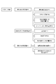
- FIG. 1 is a flow chart of a foaming suppression method according to an embodiment of the present disclosure.
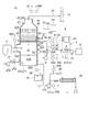
- FIG. 2 is a schematic configuration diagram schematically showing the configuration of a flue gas desulfurization system including the foam suppression system according to the embodiment of the present disclosure.
- the foaming suppression method according to some embodiments of the present disclosure will be described by exemplifying a case where it is applied to a flue gas desulfurization system as shown in FIG.
- the flue gas desulfurization system 10 discharges from a wet flue gas desulfurization device 20 for desulfurizing exhaust gas discharged from a combustion facility 11 such as an engine or a boiler, and a flue gas desulfurization device 20.
- a gypsum separator 30 for dehydrating the gypsum slurry to be produced is provided.
- the flue gas desulfurization apparatus 20 brings the exhaust gas discharged from the combustion equipment 11 into contact with the absorbing liquid to absorb sulfur oxides (for example, sulfurous acid gas) in the exhaust gas into the absorbing liquid, thereby oxidizing sulfur from the exhaust gas. It is configured to remove objects.
- sulfur oxides for example, sulfurous acid gas
- a slurry containing an alkaline component such as a limestone slurry in which limestone is dissolved (dispersed) is used as an absorption liquid
- a gypsum slurry (absorption liquid containing gypsum) is produced as a by-product.
- the slurry is not strictly a liquid, it is treated as a liquid in the present specification for convenience.
- the flue gas desulfurization apparatus 20 includes an absorption tower 20A configured to desulfurize the exhaust gas introduced into the flue gas desulfurization apparatus 20.
- the absorption tower 20A includes an absorption tower main body 22 configured to internally define an internal space 21 into which the exhaust gas discharged from the combustion equipment 11 is introduced, and an exhaust gas introduction port 23 for introducing the exhaust gas into the internal space 21. And an exhaust gas discharge port 24 for discharging exhaust gas from the internal space 21.
- the absorption tower 20A includes an exhaust gas supply line 12 for sending exhaust gas from the combustion equipment 11 to the exhaust gas introduction port 23, and an exhaust gas discharge line 14 for sending exhaust gas from the exhaust gas discharge port 24 to the chimney 13.
- the internal space 21 is located below the gas-liquid contact portion 21A for bringing the exhaust gas and the absorbed liquid into gas-liquid contact, and the sulfur oxide (for example, sulfur oxide in the exhaust gas) in the gas-liquid contact portion 21A.
- a storage unit 21B in which an absorption liquid that has absorbed (sulfurous acid gas) is stored.
- the exhaust gas introduction port 23 communicates with the internal space 21 below the gas-liquid contact portion 21A and above the storage portion 21B.
- the exhaust gas discharge port 24 communicates with the internal space 21 above the gas-liquid contact portion 21A.
- the exhaust gas discharged from the combustion equipment 11 is introduced into the internal space 21 via the exhaust gas supply line 12 and the exhaust gas introduction port 23.
- the exhaust gas guided to the internal space 21 flows while rising in the internal space 21 and is washed by the absorbing liquid when passing through the gas-liquid contact portion 21A, and sulfur oxides and the like in the exhaust gas are removed.
- the exhaust gas after the sulfur oxides and the like in the exhaust gas are removed in the gas-liquid contact portion 21A is the purified exhaust gas from the exhaust gas discharge port 24 via the exhaust gas discharge port 24 and the exhaust gas discharge line 14. Is also discharged into the atmosphere from the chimney 13 provided on the downstream side in the flow direction of the purified gas (exhaust gas).
- mist eliminator 25 configured to remove water from the purified gas (exhaust gas) is provided downstream of the gas-liquid contact portion 21A in the flow direction of the purified gas (exhaust gas). Good.
- the absorption tower 20A includes a spray device 26 arranged at the gas-liquid contact portion 21A.
- the spraying device 26 is configured to spray an absorbing liquid (limestone slurry) on the exhaust gas passing through the gas-liquid contact portion 21A.
- the absorbing liquid sprayed from the spraying device 26 comes into contact with the exhaust gas and absorbs and removes sulfur oxides (for example, sulfurous acid gas) contained in the exhaust gas.
- the spray device 26 includes a spray pipe 261 extending along a horizontal direction that intersects the flow direction of exhaust gas, and a plurality of spray nozzles 262 provided in the spray pipe 261. As shown in FIG. 2, the spray nozzle 262 has a spray port 263 that sprays the absorbing liquid toward the downstream side in the flow direction of the exhaust gas, that is, upward in the vertical direction. In some other embodiments, the spray nozzle 262 may have a spray port for spraying the absorbing liquid downward in the vertical direction.
- the exhaust gas guided to the internal space 21 is sprayed from the spray port 263 of the spray nozzle 262, and the absorbing liquid that has absorbed and removed the sulfur oxide contained in the exhaust gas falls and is stored.
- the absorption liquid stored in the storage unit 21B may include sulfites produced by sulfur oxides absorbed from exhaust gas and gypsum (calcium sulfate) produced by oxidation of sulfites.
- the absorption tower main body 22 has absorption liquid outlets 221 and 222 for extracting the absorption liquid stored in the storage unit 21B to the outside, and an oxidizing gas (for example, air) in the absorption liquid stored in the storage unit 21B.
- the nozzle insertion port 223 for inserting the supply nozzle 271 into the storage unit 21B from the outside of the absorption tower main body 22 is open.
- Each of the absorption liquid outlets 221 and 222 and the nozzle insertion port 223 communicate with the storage unit 21B.
- the absorption tower main body 22 is opened with a limestone slurry supply port 224 for introducing the limestone slurry.
- the limestone slurry supply port 224 communicates with the internal space 21 above the storage unit 21B.
- the absorption tower 20A includes a gas supply device 27 configured to supply an oxidizing gas (for example, air) to the absorption liquid stored in the storage unit 21B.
- the gas supply device 27 has a tubular nozzle 271 inserted through the nozzle insertion port 223, a pump 272 that pumps the oxidation gas to the nozzle 271, and an oxidation gas sent to the nozzle 271.
- the air in the atmosphere (oxidizing gas) is supplied into the nozzle 271 from one end side of the tubular nozzle 271 by the pump 272, and is stored in the storage unit 21B from the outlet 274 formed on the other end side of the nozzle 271. It is dispersed by the absorbing liquid. As a result, the sulfite in the absorption liquid stored in the storage unit 21B can be oxidized to form gypsum.
- the absorption tower 20A is configured to send the limestone slurry supply line 15 configured to supply the limestone slurry to the storage portion 21B of the absorption tower 20A and the absorption liquid extracted from the storage portion 21B to the spray device 26.
- the absorption liquid circulation line 16 and the absorption liquid extraction line 17 configured to send the absorption liquid extracted from the storage unit 21B to the gypsum separator 30 are included.
- the absorption tower 20A circulates the absorption liquid through the spray device 26, the storage unit 21B, and the absorption liquid circulation line 16, which are the absorption liquid circulation systems.
- the absorption liquid stored in the storage unit 21B serves as a considerable amount of desulfurization raw material for adjusting the pH of the absorption liquid that circulates while absorbing and neutralizing the sulfur oxides in the exhaust gas introduced into the absorption tower 20A to a predetermined value. Since limestone is circulated in the absorption liquid circulation system while being adjusted and supplied and repeatedly used for cleaning the exhaust gas in the absorption tower 20A, gypsum is gradually accumulated in the storage portion 21B.
- gypsum slurry (absorption liquid containing gypsum) to the gypsum separator 30 via the absorption liquid extraction line 17
- concentration of the gypsum slurry in the storage unit 21B is set to, for example, 20.
- the extraction amount is adjusted so as to be constant at ⁇ 30 wt%.
- the limestone slurry is appropriately supplied into the absorption liquid via the limestone slurry supply line 15 so that the pH of the absorption liquid in the circulation system described above is in the range of 5 to 6.
- the limestone slurry supply line 15 is arranged outside the absorption tower 20A, and one end side is connected to the limestone slurry tank 151 configured to store the limestone slurry and the limestone slurry tank 151.
- the valve 153 has a movable mechanism for opening and closing the limestone slurry supply pipe 152, and is configured to be able to adjust the amount of the limestone slurry supplied to the storage unit 21B through the limestone slurry supply pipe 152. By opening the valve 153, the limestone slurry is sent from the limestone slurry tank 151 to the storage unit 21B.
- the absorption liquid circulation line 16 is provided in the absorption liquid circulation pipe 161 and the absorption liquid circulation pipe 161 in which one end side is connected to the absorption liquid outlet 221 and the other end side is connected to the spray pipe 261.
- a circulation pump 162 configured to send the absorption liquid from one end side to the other end side of the absorption liquid circulation pipe 161 is included.
- the absorption liquid extraction line 17 is provided in the absorption liquid extraction pipe 171 and the absorption liquid extraction pipe 171 in which one end side is connected to the absorption liquid extraction outlet 222 and the other end side is connected to the plaster separator 30, and the absorption liquid extraction pipe is provided.
- Includes a extraction pump 172 configured to send the absorbing liquid from one end side to the other end side of the 171.
- the gypsum separator 30 is configured to dehydrate the gypsum slurry (absorption liquid containing gypsum) sent from the storage unit 21B via the absorption liquid extraction pipe 171 and separate it into gypsum and a filtrate.
- the foaming suppression method 1 is a method for suppressing foaming generated in the absorption liquid for desulfurizing the exhaust gas by contacting with the exhaust gas introduced into the absorption tower 20A. As shown in FIG. 1, the foaming suppressing method 1 includes a parameter value acquisition step S1, a first defoaming agent supply amount control step S2, and a second defoaming agent supply amount control step S3.
- the parameter value acquisition step S1 at least one parameter value P relating to the foaming state of the absorbing liquid is acquired.
- the acquisition of the parameter value P is continuously performed.
- the parameter value P may be acquired every moment, or may be acquired intermittently, for example, every predetermined period.
- FIG. 3 is an explanatory diagram for explaining the parameter values in one embodiment of the present disclosure.
- the parameter value P varies depending on the foaming state of the absorbing liquid stored in the storage unit 21B, and when foaming occurs in the absorbing liquid, it fluctuates greatly as compared with the case where the absorbing liquid does not foam. Will be adopted.
- the parameter value P includes the state value PA of the absorbing liquid in contact with the exhaust gas, the state value PB of the absorbing liquid pump 4 for sending the absorbing liquid in contact with the exhaust gas, and absorption. Examples include the state value PC of the exhaust gas that has come into contact with the liquid.
- the "absorption liquid in contact with the exhaust gas" corresponds to the absorption liquid stored in the storage unit 21B and the absorption liquid existing inside the absorption liquid circulation pipe 161 and the absorption liquid extraction pipe 171.
- the state value PA of the absorbing liquid in contact with the exhaust gas includes the oxidation-reduction potential PA1 of the absorbing liquid, the slurry concentration PA2 of the absorbing liquid, the supply flow rate PA3 of the absorbing liquid to the gypsum separator 30, and the temperature of the overflow pipe 9. Examples include PA4.
- the absorbent liquid pump 4 includes the above-mentioned circulation pump 162 and the above-mentioned extraction pump 172.
- Examples of the state value PB of the absorbent liquid pump 4 include a current value PB1 of the absorbent liquid pump 4, a discharge pressure PB2 of the absorbent liquid pump 4, and a flow rate PB3 of the absorbent liquid pump 4.
- Examples of the exhaust gas state value PC include a sulfur oxide concentration PC1 in the exhaust gas, a pressure difference PC2 between the exhaust gas at the inlet and the outlet of the absorption tower 20A, and the like.
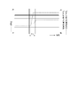
- FIGS. 4 to 7 are explanatory diagram for explaining the change in the parameter value due to the foaming of the absorbing liquid.
- the output of the combustion equipment 11 and the amount of the oxidizing gas supplied to the storage unit 21B by the gas supply device 27 are constant.
- the horizontal axes of FIGS. 4 to 7 are time axes indicating the passage of time, the time axes in FIGS. 4 to 7 are common, and the period T1 indicates the same time.
- FIG. 4 is an explanatory diagram showing a change in the redox potential with the passage of time.
- FIG. 5 is an explanatory diagram showing changes in the slurry concentration of the absorbing liquid and the flow rate of the absorbing liquid supplied to the gypsum separator with the passage of time.
- FIG. 6 is an explanatory diagram showing a change in the current value of the absorption liquid pump with the passage of time.
- FIG. 7 is an explanatory diagram showing a change in the concentration of sulfur oxides in the exhaust gas with the passage of time.
- the swing widths X1, X2, and X3 of the supply flow rate PA3 are schematically shown, but the swing width of the supply flow rate PA3 increases from X1 to X2 during the period T1.
- the value V2 of the current value PB1 of the absorption liquid pump 4 drops sharply (largely fluctuates) during the period T1.
- the swing widths Y1 and Y2 of the current value PB1 are schematically shown, but the swing width of the current value PB1 increases from Y1 to Y2 during the period T1.
- the concentration of sulfur oxides in the exhaust gas at the inlet (near the exhaust gas introduction port 23) of the absorption tower 20A during the period T1 does not fluctuate, whereas the concentration of the sulfur oxide in the exhaust gas during the period T1 does not change.
- the concentration PC1 of sulfur oxides in the exhaust gas at the outlet (near the exhaust gas discharge port 24) is rapidly increasing (varies greatly).
- Parameter values P other than the parameter values P shown in FIGS. 4 to 7 also fluctuate significantly during the period T1.
- first defoaming agent supply amount control step S2 As shown in FIG. 1, whether or not foaming is generated in the absorbing liquid is determined based on at least the parameter value P acquired in the parameter value acquisition step S1.
- first determination step S21 the determination is made (first determination step S21) and it is determined that foaming has occurred in the absorbing liquid (when "YES" in S21)
- the supply of the defoaming agent to the storage unit 21B is started or the defoaming agent is started.
- the supply amount of the above is increased (first supply amount adjustment step S22).
- the absorption tower 20A in which the predetermined amount of the defoaming agent is continuously charged at predetermined intervals, before the first supply amount adjustment step S22. It also includes increasing the amount of the defoaming agent supplied at one time and shortening the supply interval of the defoaming agent. It also includes increasing the rate of supply of the defoaming agent to the reservoir 21B. If it is determined that foaming has not occurred in the absorption liquid (in the case of "NO" in S21), the parameter value P is newly acquired while the absorption tower 20A is in operation (step S41). Based on this parameter value P, the determination in the first determination step S21 is performed again.
- the defoaming agent in the present disclosure includes silicon-based, oil-based, fatty acid-based, mineral oil-based, alcohol-based, amide-based, phosphoric acid ester-based, and metal soap-based defoaming agents.
- the parameter value P acquired before the first supply amount adjustment step S22 is set as the old parameter value OP, and the parameter value P acquired after the first supply amount adjustment step S22 is set as the new parameter value NP.
- the parameter value acquisition step S1 includes a step S1A for acquiring the old parameter value OP and a step S1B for acquiring the new parameter value NP.
- the second defoaming agent supply amount control step S3 it is determined whether or not the foaming of the absorbing liquid is eliminated at least based on the new parameter value NP acquired in the parameter value acquisition step S1.
- the supply amount of the defoaming agent to the storage unit 21B can be reduced. It is performed (second supply amount adjustment step S32).
- second supply amount adjustment step S32 In order to "reduce the amount of defoaming agent supplied to the storage unit 21B", after the first supply amount adjusting step S22 in the absorption tower 20A in which a predetermined amount of defoaming agent is continuously charged at predetermined intervals.
- the supply amount of the defoaming agent per time is reduced and the supply interval of the defoaming agent is lengthened as compared with that before the second supply amount adjusting step S32. It also includes reducing the supply rate of the defoaming agent to the storage unit 21B and stopping the supply of the defoaming agent to the storage unit 21B.
- a new parameter value NP is newly acquired while the absorption tower 20A is in operation (step S42), and at least. Based on this new parameter value NP, the determination in the second determination step S31 is performed again. Further, after the execution of the second supply amount adjustment step S32, while the operation of the absorption tower 20A is continuing (step S43), a new parameter value P is acquired, and at least based on this parameter value P, the first determination is made again. The determination in step S21 is performed.
- each step in the foam suppression method 1 is performed by the foam suppression system 5.
- the foam suppression system 5 includes at least one parameter value acquisition device 50, a defoamer storage device 6, a defoamer supply line 7, a defoamer supply amount adjusting device 8, and the defoamer supply amount adjusting device 8.
- Each step in the foam suppression method 1 may be performed by using a device or device other than the device or device of the foam suppression system 5, or may be performed manually.
- At least one parameter value acquisition device 50 is configured to acquire at least one parameter value P regarding the foaming state of the absorbing liquid. At least one parameter value P is acquired by the parameter value acquisition device 50 (parameter value acquisition step S1).
- the defoamer storage device 6 (for example, a defoamer storage tank) is configured to store the defoamer.
- the defoamer storage device 6 is arranged outside the absorption tower 20A.
- the defoaming agent supply line 7 is configured to send the defoaming agent from the defoaming agent storage device 6 to the storage unit 21B.
- the defoaming agent supply port 225 for introducing the defoaming agent is opened in the absorption tower main body 22.
- the defoamer supply port 225 communicates with the internal space 21 above the storage unit 21B.
- the defoamer supply line 7 includes a defoamer supply pipe 71 having one end connected to the defoamer storage device 6 and the other end connected to the defoamer supply port 225.
- the defoaming agent supply amount adjusting device 8 is configured to be able to adjust the amount of the defoaming agent sent from the defoaming agent storage device 6 to the storage unit 21B through the defoaming agent supply line 7. "Adjusting the amount of defoaming agent” includes starting and stopping the supply of the defoaming agent. Each of the first defoamer supply amount control step S2 and the second defoamer supply amount control step S3 is performed by the defoamer supply amount adjusting device 8.
- the defoamer supply amount adjusting device 8 is an adjusting mechanism for adjusting the amount of the defoaming agent sent from the defoaming agent storage device 6 to the storage unit 21B, as shown in FIG.
- a defoaming agent supply amount adjusting unit 81 having a defoaming agent supply amount adjusting unit 81, and a control device 82 (FIG. 8) configured to instruct the operation of the adjusting mechanism to the defoaming agent supply amount adjusting unit 81.
- the defoaming agent supply amount adjusting unit 81 includes a valve 81A provided in the defoaming agent supply pipe 71.
- the valve 81A has a movable mechanism for opening and closing the defoaming agent supply pipe 71, and the amount of the defoaming agent supplied to the storage unit 21B through the defoaming agent supply pipe 71 can be adjusted by the movable mechanism. It is configured in.
- FIG. 8 is a block diagram showing the function of the defoamer supply amount adjusting device according to the embodiment of the present disclosure.
- the control device 82 includes a database unit 83, a determination data generation unit 84, a first determination unit 85, a second determination unit 86, and an eraser.
- the foaming agent supply amount indicator 87 and the like are included.
- the database unit 83 is configured to store the parameter value P acquired by the parameter value acquisition device 50 together with the time series information.
- the determination data generation unit 84 is configured to generate determination data from the information (for example, the parameter value P) stored in the database unit 83.
- the first determination unit 85 determines whether or not foaming has occurred in the absorbing liquid so as to perform the first determination step S21, that is, based on at least the old parameter value OP (parameter value P). It is configured in.
- the second determination unit 86 determines whether or not the foaming of the absorbing liquid has been eliminated so as to perform the second determination step S31, that is, based on at least the new parameter value NP (parameter value P). It is configured.
- the defoamer supply amount indicating unit 87 is configured to instruct the valve 81A of the opening degree according to the determination result of at least one of the first determination unit 85 and the second determination unit 86.
- the valve 81A is electrically controlled by a signal sent from the defoaming agent supply amount indicating unit 87, and is configured to have an instructed opening degree in response to the signal.
- the defoaming agent supply amount indicating unit 87 increases the opening degree of the valve 81A (for example, fully open). ) (First supply amount adjustment step S22).
- the valve 81A increases its opening degree in response to the instruction of the defoaming agent supply amount indicating unit 87, starts supplying the defoaming agent to the storage unit 21B, or increases the supply amount of the defoaming agent.
- the defoaming agent supply amount indicating unit 87 reduces the opening degree of the valve 81A (for example, all). (Closed) is instructed (second supply amount adjustment step S32).
- the valve 81A reduces its opening degree in response to the instruction of the defoaming agent supply amount indicating unit 87, and reduces the amount of the defoaming agent supplied to the storage unit 21B. At this time, the valve 81A may be fully closed to stop the supply of the defoaming agent to the storage unit 21B.
- the control device 82 is an electronic control unit for controlling the supply amount of the defoaming agent to the storage unit 21B, and is a CPU (processor) (not shown), a memory such as ROM or RAM, a storage device such as an external storage device, or I. It may be configured as a microcomputer including a / O interface, a communication interface, and the like. Then, for example, the above-mentioned parts may be realized by the CPU operating (for example, data calculation) according to the instruction of the program loaded in the main storage device of the memory.
- the foaming suppressing method 1 includes the above-mentioned parameter value acquisition step S1, the above-mentioned first defoaming agent supply amount control step S2, and the above-mentioned second defoaming agent supply amount control step S2.
- a defoaming agent supply amount control step S3 is provided.
- at least one parameter value P relating to the foaming state of the absorbing liquid is acquired in the parameter value acquisition step S1.
- This parameter value P fluctuates according to the foaming state of the absorbing liquid stored in the storage unit 21B, and when foaming occurs in the absorbing liquid, it fluctuates greatly as compared with the case where foaming does not occur in the absorbing liquid.
- the amount of the defoaming agent supplied to the storage unit 21B is reduced (second defoaming agent supply amount control). Since the excessive supply of the defoaming agent after step S3) can be suppressed, the deterioration of the oxidizing performance of the absorbing liquid can be suppressed.
- the foam suppression system 5 suppresses foaming generated in the absorption liquid for desulfurizing the exhaust gas by contacting the exhaust gas introduced into the absorption tower 20A.
- the defoamer supply amount adjusting device 8 determines whether or not foaming has occurred in the absorbing liquid based on at least the parameter value P (old parameter value OP) acquired by the parameter value acquiring device 50, and makes the absorbing liquid into the absorbing liquid.
- the supply of the defoaming agent to the storage unit 21B is started or the amount of the defoaming agent is increased, and at least the parameter value acquired by the parameter value acquisition device 50 is configured.
- P new parameter value NP
- At least one parameter value P regarding the foaming state of the absorbing liquid is acquired by at least one parameter value acquisition device 50.
- This parameter value P varies depending on the foaming state of the absorbing liquid stored in the storage unit 21B.
- the defoaming agent supply amount adjusting device 8 is used to supply the defoaming agent to the storage unit 21B.
- the foaming state of the absorbing liquid stored in the storage unit 21B can be estimated accurately, and the foaming of the absorbing liquid can be quickly performed. Can be suppressed.
- the defoaming agent supply amount adjusting device 8 reduces the amount of the defoaming agent supplied to the storage unit 21B. Since the excessive supply of the defoamer can be suppressed, the deterioration of the oxidation performance of the absorbing liquid can be suppressed.
- the at least one parameter value P described above comprises the redox potential PA1 of the absorption liquid in contact with the exhaust gas.
- the at least one parameter value acquisition device 50 includes a redox potential meter (ORP meter) 51 configured to acquire the redox potential of the absorption liquid in contact with the exhaust gas.
- the redox potential meter 51 is provided in the absorption liquid circulation line 16 and measures the redox potential of the absorption liquid flowing through the absorption liquid circulation pipe 161.
- the redox potential (ORP value) PA1 of the absorption liquid acquired in the parameter value acquisition step S1 rises sharply.
- the redox potential PA1 of the absorption liquid as the parameter value P described above, the foaming state of the absorption liquid stored in the storage unit 21B can be estimated accurately.
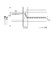
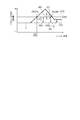
- FIG. 9 is an explanatory diagram for explaining an example of determination in one embodiment of the present disclosure.
- L in FIG. 9 is an estimated straight line calculated from the redox potential (ORP value) PA1 acquired by the redox potential meter 51.
- the at least one parameter value P described above comprises the redox potential PA1 of the absorption liquid in contact with the exhaust gas.
- the appropriate range R1 of the redox potential PA1 of the absorption liquid in contact with the exhaust gas is defined in advance by the upper limit value UT1 and the lower limit value LT1.
- the appropriate range R1 (upper limit value UT1, lower limit value LT1) is set in advance before the first determination step S21 and is stored in the database unit 83.
- the defoamer supply amount adjusting device 8 compares the measured value of the redox potential PA1 acquired by the redox potential meter 51 with the appropriate range R1, adjusts the opening degree of the valve 81A, and erases the valve 81A into the storage unit 21B. Adjust the amount of foam supplied.
- the redox potential PA1 of the absorption liquid is in a peroxidation state exceeding the upper limit value UT1, there is a possibility that peroxide is generated in the absorption liquid.
- the measured value of the redox potential PA1 acquired by the redox potential meter 51 is compared with the upper limit value UT1, and the measured value becomes the upper limit value UT1.
- point P1 or when the measured value exceeds the upper limit value UT1 it is determined that foaming has occurred in the absorbing liquid.
- the valve 81A increases its opening degree and starts supplying the defoaming agent to the storage unit 21B (first supply amount adjusting step S22).
- the upper limit value UT1 is preferably 100 mV or more and 600 mV or less. In some embodiments, the upper limit UT1 is 400 mV.
- the oxidation-reduction potential PA1 of the absorption liquid is lower than the lower limit value LT1
- the oxidation performance of the absorption liquid is significantly lowered, so that the desulfurization performance of the exhaust gas by the absorption liquid is lowered, and the flue gas desulfurization apparatus 20 (absorption tower 20A) It may be difficult to maintain sound operation.
- the second determination step S31 the measured value of the redox potential PA1 acquired by the redox potential meter 51 is compared with the lower limit value LT1, and the measured value becomes the lower limit value LT1.
- the valve 81A closes its opening fully and stops supplying the defoaming agent to the storage unit 21B (second supply amount adjusting step S32).
- the redox potential PA1 of the absorbing liquid becomes the lower limit value LT1 or less
- the supply of the defoaming agent to the storage unit 21B is stopped, so that the absorbing liquid due to the excessive supply of the defoaming agent Since the deterioration of the oxidation performance of the flue gas desulfurization apparatus 20 can be suppressed, the sound operation of the flue gas desulfurization apparatus 20 can be maintained.
- the lower limit value LT1 is preferably 50 mV or more and 400 mV or less. In some embodiments, the lower limit LT1 is 50 mV.
- the measured value of the redox potential PA1 acquired by the redox potential meter 51 after the second supply amount adjusting step S32 is a predetermined value having a value larger than the lower limit value LT1 (for example, the upper limit).
- the value UT1) is reached or the value exceeds a predetermined value
- the supply of the defoaming agent to the storage unit 21B may be started. Further, as a condition for starting the supply of the defoaming agent to the storage unit 21B, it may be added that the sulfite concentration of the absorption liquid measured by the sulfite concentration meter 18 (see FIG. 2) is not more than a predetermined concentration. ..
- the sulfite concentration meter 18 is provided in the absorption liquid circulation line 16 and is configured to measure the concentration of sulfite in the absorption liquid flowing through the absorption liquid circulation pipe 161.
- the foaming suppression method 1 described above further comprises a defoaming agent supply amount adjusting step S5, as shown in FIG.
- a defoaming agent supply amount adjusting step S5 Prior to the defoamer supply amount adjusting step S5, each of the maximum value UV1 and the minimum value UV2 of the parameter value P assumed according to the type of the parameter value P, and at least one between the maximum value UV1 and the minimum value UV2.
- An intermediate value IV which is one of the two values, is defined and stored in the database unit 83.
- the defoaming agent supply amount adjusting step S5 when the parameter value P reaches the intermediate value IV, the amount of the defoaming agent supplied to the storage unit 21B is adjusted.
- the defoaming agent supply amount adjusting device 8 is configured to be able to execute the defoaming agent supply amount adjusting step S5.
- the upper limit value UT1 is defined as one of the intermediate values IV.
- the defoamer supply amount adjusting device 8 sets the measured value to the upper limit value. It is configured to increase the supply amount of the defoaming agent to the storage portion 21B as compared with the case of less than UT1. For example, it may be configured to increase the opening degree of the valve 81A, or it may be configured to open the valve 81A and increase the number of times the defoaming agent is supplied.
- the threshold value TH which is smaller than the upper limit value UT1 and larger than the lower limit value LT1 as one of the intermediate values IV, is preset before the defoamer supply amount adjusting step S5. It is stored in the database unit 83.
- the defoaming agent is supplied to the storage unit 21B as compared with the case where the measured value exceeds the threshold value TH. It is configured to reduce the amount. For example, the opening degree of the valve 81A may be reduced, or the valve 81A may be opened to reduce the number of times the defoaming agent is supplied.
- the threshold TH is 100 mV.
- a plurality of intermediate values IV may be specified, and each time the measured value becomes one of the plurality of intermediate values IV, the defoaming agent to the storage unit 21B is used. The supply may be adjusted.
- the defoaming agent is excessively supplied or insufficiently supplied. Can be effectively suppressed.
- the appropriate range (upper limit value, lower limit value) of each parameter value P is set in advance before the first determination step S21, and the database unit is used. It may be stored in 83. Further, for each of the parameter values P other than the redox potential PA1 of the absorbing liquid, the maximum and minimum values of the parameter values assumed according to the type of each parameter value P, and the intermediate value between them are erased. It may be set in advance before the foaming agent supply amount adjusting step S5 and stored in the database unit 83. Further, with respect to each of the parameter values P other than the redox potential PA1 of the absorbing liquid, the amount of the defoaming agent supplied to the storage unit 21B may be increased or decreased when each parameter value reaches an intermediate value.
- FIG. 10 is an explanatory diagram for explaining an example of determination in one embodiment of the present disclosure.
- the measured value of the parameter value P is used when determining the foaming state of the absorbing liquid (for example, in the first determination step S21 and the second determination step S31).
- At least one of the fluctuation width, mean value, variance, standard deviation, effective value, fluctuation amount, fluctuation rate, and difference amount of the parameter value P calculated from the measured value of the parameter value is used as the judgment data. May be good.
- the determination data generation unit 84 is configured to generate determination data such as an average value of the parameter value P from the measured value of the parameter value P.
- the determination data in the first determination step S21 (first determination unit 85), the determination data (in FIG. 10, the fluctuation amount ⁇ P of the parameter value P in the predetermined period T2).
- a predetermined threshold value point P3
- the second determination step S31 second determination unit 86
- the determination data becomes equal to or less than a predetermined threshold value, it may be determined that the foaming of the absorbing liquid has been eliminated.
- FIG. 11 is an explanatory diagram for explaining a method of setting a threshold value in one embodiment of the present disclosure.
- the determination criteria such as the appropriate range (upper limit value, lower limit value) and the threshold value of the parameter value P are the determination of the foaming state of the absorbing liquid (for example, the first determination step S21, the second determination step S21, the second.
- the data set in advance before the determination step S31) and stored in the database unit 83 is referred to at the time of determination, etc., but the determination of the foaming state of the absorbing liquid (for example, the first determination step) At the time of S21, the second determination step S31), etc., or before that, the determination data generation unit 84 generates the data based on the data stored in the database unit 83 (for example, the measured value of the parameter value P). You may.
- the determination data generation unit 84 includes an appropriate range R2 (within the range) the parameter value P at the time when it is determined that foaming has occurred in the absorbing liquid (point P3).
- the upper limit value UT2 and the lower limit value LT2) may be generated.
- the appropriate range R2 generated by the determination data generation unit 84 may be used as the determination standard in the second determination step S31.
- second determination step S31 second determination unit 86
- when the newly acquired parameter value P is within the appropriate range R2 (point P4) it is determined that the foaming of the absorbing liquid has been eliminated. It may be.
- the determination data generation unit 84 sets the parameter value P in the stable state before the time (point P3) when it is determined that the absorption liquid is foamed within the range.
- An appropriate range R2 (upper limit value UT2, lower limit value LT2) including the appropriate range R2 may be generated and used as a determination criterion in the second determination step S31.
- the determination data generation unit 84 has foamed in the absorbing liquid at least based on the parameter value P (old parameter value OP) acquired in the parameter value acquisition step S1.
- the predicted value PV of the parameter value assuming that there is no parameter value may be generated.
- the predicted value PV generated by the determination data generation unit 84 may be used as a determination index in each determination (for example, the first determination step S21 and the second determination step S31).
- first determination step S21 first determination unit 85
- the absorbing liquid may be used. It may be determined that the foaming of the above has been eliminated.
- a preset value may be stored in the database unit 83.
- the fluctuation width of the parameter value P (for example, X1 to X3 in FIG. 5 and Y1 and Y2 in FIG. 6) is the parameter value P. It may be determined that foaming has occurred in the absorbing liquid when it exceeds the predetermined swing width (for example, the predicted swing width of the parameter value assuming that the absorbing liquid does not have foaming). Further, in the second determination step S31 (second determination unit 86), the swing width of the parameter value P is a predetermined swing width (for example, prediction of the parameter value assuming that foaming does not occur in the absorbing liquid). When it becomes less than or equal to the swing width), it may be determined that the foaming of the absorbing liquid has been eliminated. A preset value may be stored in the database unit 83, or the predetermined fluctuation width may be generated by the determination data generation unit 84.
- the parameter value P acquired in the parameter value acquisition step S1 and the parameter value assuming that the absorbent liquid is not foamed Based on the predicted value PV and, it is determined whether or not foaming is generated in the absorbing liquid. It should be noted that the swing width of the parameter value P and the swing width of the predicted value PV may be compared to determine whether or not foaming has occurred in the absorbing liquid.
- the parameter value P varies depending on the foaming state of the absorbing liquid stored in the storage unit 21B, and when foaming occurs in the absorbing liquid, the parameter value P is compared with the case where foaming does not occur in the absorbing liquid. , The deviation of the parameter value from the predicted value PV becomes large.
- the parameter value P acquired in the parameter value acquisition step S1 has a large deviation from the predicted value PV of the parameter value, it is highly probable that foaming has occurred in the absorption liquid stored in the storage unit 21B.
- first defoaming agent supply amount control step S2 By starting the supply of the defoaming agent to the storage unit 21B or increasing the supply amount of the defoaming agent, the foaming of the absorbing liquid is rapidly suppressed.
- the foaming state of the absorbing liquid stored in the storage unit 21B can be estimated accurately, and the foaming of the absorbing liquid can be estimated. Can be quickly suppressed.
- the parameter value P acquired in the parameter value acquisition step S1 and the parameter value assuming that the absorbent liquid is not foamed Based on the predicted value PV, it is determined whether or not the foaming of the absorbing liquid has been eliminated. It should be noted that the swing width of the parameter value P and the swing width of the predicted value PV may be compared to determine whether or not the foaming of the absorbing liquid has been eliminated.
- the determination data generation unit 84 was acquired at least before the determination of the foaming state of the absorbing liquid (for example, the first determination step S21 and the second determination step S31). From the measured value of the parameter value P, the frequency distribution is calculated with respect to the predicted value PV of the parameter value P and the deviation of each measured value with respect to the predicted value PV, and the predicted value PV of the parameter value P (deviation is 0) is included from the frequency distribution.
- An appropriate range R3 (upper limit value UT3, lower limit value LT3) may be generated and used as a determination criterion in each determination (for example, first determination step S21, second determination step S31).
- the proper range R3 is set to include 80% of the measured value of the parameter value P.
- the foam suppression method 1 in the foam suppression method 1 described above, it is determined that foaming has occurred in the absorbing liquid during the supply of the defoaming agent to the storage unit 21B.
- the old parameter value OP and the new parameter value NP which are parameter values of either the time point (point P3) or the time point when it is determined that foaming does not occur in the absorbent liquid before the time point of foaming (point P3).
- the defoaming agent supply amount is adjusted according to the difference D1.
- the second determination unit 86 compares the old parameter value OP and the new parameter value NP, and when the difference D1 is less than the preset allowable value D0, the storage unit 21B is deleted. The amount of foaming agent supplied is reduced.
- the difference D can be reduced by comparing the new parameter value NP and the old parameter value OP and adjusting the amount of the defoaming agent supplied according to the difference D1. Can be brought closer to the state before the parameter value P fluctuates greatly due to foaming. In this case, it is possible to effectively suppress the excessive supply and shortage of the defoaming agent.
- the at least one parameter value P described above comprises the slurry concentration PA2 of the absorbent.
- the at least one parameter value acquisition device 50 includes a slurry concentration meter 52 configured to acquire the slurry concentration PA2 of the absorbing liquid in contact with the exhaust gas.
- the slurry concentration meter 52 is provided on the absorption liquid circulation line 16 and measures the slurry concentration of the absorption liquid flowing through the absorption liquid circulation pipe 161.
- the slurry densitometer 52 comprises a differential pressure type slurry densitometer that converts the pressure difference of the absorbing liquid generated between the two points into the slurry concentration. In this case, as shown in FIG.
- the value of the slurry concentration PA2 of the absorbing liquid becomes smaller than that in the case where the absorbing liquid does not foam, and the value of the slurry concentration PA2 is smaller than the predicted value of the slurry concentration PA2.
- the deviation becomes large.
- the parameter value P (for example, the slurry concentration PA2 of the absorption liquid) may vary depending on the operation data of the plant including the absorption tower 20A, in some embodiments, the absorption liquid at the time when the absorption liquid is not foamed.
- Plant operation data is taken into account when predicting the slurry concentration PA2 of.
- the plant operation data includes the flow rate of exhaust gas introduced into the internal space 21 of the absorption tower 20A, the concentration of sulfurous acid gas in the exhaust gas, the amount of gypsum slurry sent to the gypsum separator 30 via the absorption liquid extraction line 17, and absorption. At least one of the amounts of limestone slurry supplied through the limestone slurry supply port 224 of the tower body 22 is included.
- the at least one parameter value P described above includes at least one of the current value PB1 of the absorption liquid pump 4 and the parameter obtained by numerically analyzing the current value PB1.
- the parameters include the fluctuation width and standard deviation of the current value PB1 obtained from the measured values.
- At least one parameter value acquisition device 50 is configured to acquire the current value of the ammeter 53A configured to acquire the current value of the circulation pump 162 and the extraction pump 172 as shown in FIG. Includes at least one of the ammeters 53B. In this case, as shown in FIG.
- the specific gravity of the absorbing liquid becomes lighter and the load applied to the absorbing liquid pump 4 becomes smaller, so that the case where the absorbing liquid does not foam is compared with the case where the absorbing liquid does not foam.
- the value of the current value PB1 of the absorbent pump 4 becomes smaller, and the fluctuation width of the current value PB1 becomes larger.
- the at least one parameter value P described above includes at least one of the discharge pressure PB2 of the absorption liquid pump 4 and the swing width of the discharge pressure PB2.
- At least one parameter value acquisition device 50 is configured to acquire the discharge pressure of the pressure gauge 54A configured to acquire the discharge pressure of the circulation pump 162 and the extraction pump 172 as shown in FIG. Includes at least one of the pressure gauges 54B.
- the pressure gauge 54A is provided on the downstream side of the circulation pump 162 of the absorption liquid circulation line 16.
- the pressure gauge 54B is provided on the downstream side of the extraction pump 172 of the absorption liquid extraction line 17.
- the value of the current value PB1 of the absorbing liquid pump 4 becomes smaller and the fluctuation width of the current value PB1 becomes larger as compared with the case where the absorbing liquid does not foam.
- the value of the discharge pressure PB2 of the absorbing liquid pump 4 becomes small, and the swing width of the discharge pressure PB2 becomes large.
- the at least one parameter value P described above includes at least one of the flow rate PB3 of the absorption liquid pump 4 and the swing width of the flow rate PB3.
- At least one parameter value acquisition device 50 is configured to acquire the flow rate of the flow meter 55A configured to acquire the flow rate of the circulation pump 162 and the extraction pump 172 as shown in FIG. Includes at least one of the flow meters 55B.
- the flow meter 55A is provided on the downstream side of the circulation pump 162 of the absorption liquid circulation line 16.
- the flow meter 55B is provided on the downstream side of the extraction pump 172 of the absorption liquid extraction line 17.
- the value of the current value PB1 of the absorbing liquid pump 4 becomes smaller and the fluctuation width of the current value PB1 becomes larger than in the case where the absorbing liquid does not foam.
- the value of the flow rate PB3 of the absorption liquid pump 4 becomes small, and the fluctuation width of the flow rate PB3 becomes large.
- the at least one parameter value P described above is the gypsum separator 30 for the absorption liquid flowing through the pipe (absorption liquid extraction pipe 171) for supplying the absorption liquid from the storage unit 21B to the gypsum separator 30.
- At least one parameter value acquisition device 50 includes a flow meter 56 configured to acquire the supply flow rate of the absorption liquid flowing through the absorption liquid extraction pipe 171 to the gypsum separator 30 as shown in FIG. Including.
- the flow meter 56 is provided on the downstream side of the circulation pump 162 of the absorption liquid circulation line 16.
- the absorbing liquid is driven by the absorbing liquid pump 4 (specifically, the extraction pump 172), flows from the storage unit 21B through the pipe 171 and is supplied to the gypsum separator 30.
- the value of the current value PB1 of the absorbing liquid pump 4 (extraction pump 172) becomes smaller than that in the case where the absorbing liquid does not foam, and the current value (PB1).
- the swing width of the above pipe 171 increases, the value of the supply flow rate PA3 of the absorbing liquid flowing through the pipe 171 to the gypsum separator 30 decreases, and the swing width of the supply flow rate PA3 increases.
- the foaming state of the absorbing liquid stored in the storage unit 21B can be estimated accurately.
- the at least one parameter value P described above deviates from the predicted parameters of the sulfur oxide concentration PC1 in the exhaust gas and the sulfur oxide concentration PC1 in the exhaust gas in contact with the absorbing liquid. Of these, at least one of them is included.
- At least one parameter value acquisition device 50 is configured to acquire the sulfur oxide concentration PC1 in the exhaust gas in contact with the absorbing liquid as shown in FIG. 2 (for example, a sulfur oxide concentration meter 57 (for example). SO 2 densitometer) is included.
- the sulfur oxide concentration meter 57 is provided in the exhaust gas discharge line 14.
- the storage unit 21B can be used. The foaming state of the stored absorption liquid can be estimated accurately.
- the at least one parameter value P described above is the predicted parameter of the pressure difference PC2, the pressure difference PC2, between the pressure of the exhaust gas at the inlet of the absorption tower 20A and the pressure of the exhaust gas at the outlet of the absorption tower 20A. Includes at least one of the deviations of.
- At least one parameter value acquisition device 50 obtains the pressure of the exhaust gas at the outlet of the absorption tower 20A and the pressure gauge 58A configured to acquire the pressure of the exhaust gas at the inlet of the absorption tower 20A as shown in FIG. Includes a pressure gauge 58B, which is configured to acquire.
- the pressure gauge 58A is provided in the vicinity of the exhaust gas introduction port 23 in the exhaust gas supply line 12, and the pressure gauge 58B is provided in the vicinity of the exhaust gas discharge port 24 in the exhaust gas discharge line 14.
- the determination data generation unit 84 is configured to calculate the pressure difference PC2 from the inlet pressure acquired by the pressure gauge 58A and the outlet pressure acquired by the pressure gauge 58B. In this case, when the absorbing liquid foams, the circulating flow rate of the absorbing liquid fluctuates and the liquid level of the absorbing liquid in the storage unit 21B becomes unstable. As the swing width of the difference PC2 increases, the deviation of the pressure difference PC2 from the predicted value PV increases.
- the exhaust gas is stored in the storage unit 21B.
- the foaming state of the absorbed liquid can be estimated accurately.
- the at least one parameter value P described above includes the temperature PA4 of the overflow pipe 9 connected to the reservoir 21B.
- the overflow pipe 9 is configured so that the absorption liquid flows from the storage unit 21B when the liquid level of the absorption liquid in the storage unit 21B exceeds a predetermined liquid level.
- the absorption liquid that has flowed in from one end side of the overflow pipe 9 is discharged from the other end side of the overflow pipe 9 and is stored in the absorption liquid tank 91 configured to store the absorption liquid.
- At least one parameter value acquisition device 50 includes a thermometer 59 configured to acquire the temperature PA4 of the overflow pipe 9 as shown in FIG. In the illustrated embodiment, the thermometer 59 measures the temperature of the outer surface of the overflow pipe 9 projecting to the outside of the absorption tower 20A. In this case, it is possible to easily measure the temperature PA4 of the overflow pipe 9.
- the temperature PA4 of the overflow pipe 9 rises as compared with the case where the absorbing liquid does not foam.
- a plurality of parameter values P (see FIG. 3) having different types of parameter values P are acquired.
- the fact that the types of the parameter values P are different means that the symbols attached to the respective parameter values are different, for example, the redox potential PA1 and the slurry concentration PA2 of the absorbing liquid shown in FIG. ..
- the first defoaming agent supply amount control step S2 described above it is said that foaming has occurred in the absorbing liquid based on at least two parameter values P among the plurality of parameter values P acquired in the parameter value acquisition step S1.
- the second defoaming agent supply amount control step S3 foaming of the absorbing liquid is eliminated based on at least two parameter values P among the plurality of parameter values P acquired in the parameter value acquisition step S1.
- the amount of the defoaming agent supplied to the storage unit 21B may be reduced when it is determined that the treatment has been performed.
- a plurality of parameter values P having different types of parameter values P are acquired in the parameter value acquisition step S1.
- the absorbing liquid stored in the storage unit 21B has a larger fluctuation than when one parameter value P fluctuates significantly. Since there is a high probability of foaming, by starting the supply of the defoaming agent to the storage unit 21B or increasing the supply amount of the defoaming agent (first defoaming agent supply amount control step S2), Foaming of the absorbing liquid can be suppressed quickly and accurately.
- the foaming state of the absorbing liquid stored in the storage unit 21B is estimated accurately. It is possible to suppress the foaming of the absorbing liquid quickly and accurately.
- a plurality of parameter values P (see FIG. 3) having different types of parameter values P are acquired.
- the first defoaming agent supply amount control step S2 described above it is said that foaming has occurred in the absorbing liquid based on at least two parameter values P among the plurality of parameter values P acquired in the parameter value acquisition step S1.
- the supply of the defoaming agent to the storage unit 21B is started or the supply amount of the defoaming agent is increased.
- the at least two parameter values P include the redox potential PA1 of the absorbing liquid in contact with the exhaust gas.
- the redox potential PA1 of the absorbing liquid is excellent as an estimation index of the foaming state of the absorbing liquid. According to the above method, by setting one of at least two parameter values P described above as the redox potential PA1 of the absorbing liquid, the foaming state of the absorbing liquid stored in the storage unit 21B can be estimated accurately. As a result, foaming of the absorbing liquid can be suppressed quickly and accurately.
- the parameter value P does not fluctuate according to the supply amount of the oxidation gas (FIG. 3).
- the opening degree of the adjusting valve 273 is not changed. May be good.
- the fluctuation of the redox potential PA1 of the absorbing liquid due to the fluctuation of the supply amount of the oxidizing gas can be suppressed, the estimation accuracy of the foaming state of the absorbing liquid by the redox potential PA1 of the absorbing liquid can be improved. Can be done.
- a plurality of parameter values P having different classifications of the parameter values P (absorption liquid state value PA, absorption liquid pump state value PB, exhaust gas state value PC). (See FIG. 3) is acquired.
- the first defoaming agent supply amount control step S2 described above it is said that foaming has occurred in the absorbing liquid based on at least two parameter values P among the plurality of parameter values P acquired in the parameter value acquisition step S1.
- the supply of the defoaming agent to the storage unit 21B is started or the supply amount of the defoaming agent is increased.
- the foaming state of the absorbing liquid stored in the storage unit 21B can be changed from various aspects. Since it can be estimated, the foaming state of the absorbing liquid stored in the storage unit 21B can be estimated accurately.
- the present disclosure is not limited to the above-described embodiment, and includes a modified form of the above-described embodiment and a combination of these embodiments as appropriate.
- the foaming suppression method (1) is A foaming suppression method (1) for suppressing foaming generated in an absorption liquid for desulfurizing the exhaust gas by contacting the exhaust gas introduced into the absorption tower (20A).
- a parameter value acquisition step (S1) for acquiring at least one parameter value (P) relating to the foaming state of the absorbing liquid, and a parameter value acquisition step (S1). Based on the parameter value (P) acquired in the parameter value acquisition step (S1), it was determined whether or not foaming had occurred in the absorbing liquid, and it was determined that foaming had occurred in the absorbing liquid.
- the supply of the defoaming agent to the storage unit (21B) configured to store the absorbing liquid in contact with the exhaust gas is started or the supply amount of the defoaming agent is increased.
- At least one parameter value (P) relating to the foaming state of the absorbing liquid is acquired in the parameter value acquisition step (S1).
- This parameter value (P) fluctuates according to the foaming state of the absorbing liquid stored in the storage portion (21B), and when foaming occurs in the absorbing liquid, it is larger than that in the case where the absorbing liquid does not foam. fluctuate. If the parameter value (P) fluctuates significantly, it is highly probable that foaming has occurred in the absorbent liquid stored in the storage section (21B), so supply of the defoaming agent to the storage section (21B) is started.
- the foaming of the absorbing liquid can be rapidly suppressed.
- the method 1) above by adopting the parameter value (P) as an estimation index of the foaming state of the absorbing liquid, the foaming state of the absorbing liquid stored in the storage portion (21B) can be accurately estimated and absorbed. The foaming of the liquid can be suppressed quickly.
- the foaming suppression method (1) according to 1) above is used.
- the predicted value (PV) and the value it is determined whether or not foaming is generated in the absorption liquid.
- the parameter value (P) fluctuates according to the foaming state of the absorbing liquid stored in the storage portion (21B), and when foaming occurs in the absorbing liquid, foaming occurs in the absorbing liquid.
- the deviation of the parameter value from the predicted value (PV) is larger than that in the case where the parameter value is not set.
- the parameter value (P) acquired in the parameter value acquisition step (S1) has a large deviation from the predicted value (PV) of the parameter value, foaming occurs in the absorbing liquid stored in the storage unit (21B).
- the foaming state of the absorbing liquid stored in the storage unit (21B) is estimated accurately by adopting the predicted value (PV) of the parameter value as a determination index of the foaming state of the absorbing liquid. It is possible to quickly suppress the foaming of the absorbing liquid.
- the foaming suppression method (1) according to 1) or 2) above. At least one value between the maximum value (UV1) and the minimum value (LV2) of the assumed parameter value (P) is defined as an intermediate value (IV), and the parameter value (P) is the intermediate value (IV). ),
- the defoamer supply amount adjusting step (S5) for adjusting the supply amount of the defoaming agent to the storage unit (21B) is further provided.
- the defoaming agent is extinguished by adjusting the amount of the defoaming agent supplied to the storage unit (21B) according to the parameter value (P) in the defoaming agent supply amount adjusting step (S5). It is possible to effectively suppress the oversupply and shortage of foaming agent.
- the at least one parameter value (P) includes the redox potential (PA1) of the absorption liquid, which is the state value (PA) of the absorption liquid in contact with the exhaust gas.
- the value of the redox potential (PA1) of the absorption liquid acquired in the parameter value acquisition step (S1) rises sharply.
- the redox potential (PA1) of the absorbing liquid as the above-mentioned parameter value (P)
- the foaming state of the absorbing liquid stored in the storage portion can be estimated accurately.
- the foaming suppression method (1) according to 4) above is used.
- the appropriate range (R1) of the redox potential (PA1) of the absorption liquid is defined in advance by the upper limit value (UT1) and the lower limit value (LT1), and during the supply of the defoaming agent to the storage portion (21B).
- the redox potential (PA1) of the absorption liquid reaches the lower limit value (LT1) or falls below the lower limit value (LT1), the defoaming agent is added to the storage portion (21B). Stop supply.
- the oxidation-reduction potential of the absorption liquid falls below the lower limit, the oxidation performance of the absorption liquid will be significantly reduced, and the desulfurization performance of the exhaust gas by the absorption liquid will be reduced, making it difficult to maintain the sound operation of the flue gas desulfurization equipment. There is a risk of becoming.
- the method of 5) above when the redox potential of the absorbing liquid falls below the lower limit value, the supply of the defoaming agent to the storage portion is stopped, so that the absorbing liquid due to the excessive supply of the defoaming agent is used. Since the deterioration of the oxidation performance can be suppressed, the sound operation of the flue gas desulfurization apparatus can be maintained.
- the foaming suppression method (1) according to any one of 1) to 5) above.
- foaming did not occur in the absorbing liquid at the time when foaming was determined to have occurred in the absorbing liquid or before the foaming generation time.
- the old parameter value (OP) which is the parameter value at any one of the time points determined to be, is compared with the new parameter value (NP), and the defoamer supply amount is adjusted according to the difference (D1). To do.
- the difference can be reduced by comparing the new parameter value (NP) and the old parameter value (OP) and adjusting the amount of defoaming agent supplied according to the difference. It is possible to approach the state before the absorption liquid foams and the parameter value (P) fluctuates greatly. In this case, it is possible to effectively suppress the excessive supply and shortage of the defoaming agent.
- the at least one parameter value (P) includes a slurry concentration (PA2) of the absorption liquid, which is a state value (PA) of the absorption liquid in contact with the exhaust gas.
- the value of the slurry concentration (PA2) of the absorbing liquid becomes smaller than that in the case where the absorbing liquid does not foam, and the value of the slurry concentration (PA2) is relative to the predicted value.
- the deviation becomes large.
- the at least one parameter value (P) is a state value (PB) of the absorbent liquid pump (4) for feeding the absorbent liquid, and is a current value (PB1) and a current of the absorbent liquid pump (4). It includes at least one of the parameters obtained by numerically analyzing the value (PB1).
- the specific gravity of the absorbent liquid becomes lighter and the load applied to the absorbent liquid pump becomes smaller. Therefore, the current of the absorbent liquid pump is smaller than that in the case where the absorbent liquid is not foamed.
- the value of the value (PB1) becomes smaller, and the fluctuation range of the current value (PB1) becomes larger.
- the at least one parameter value (P) is the state value (PB) of the absorbent liquid pump (4) for feeding the absorbent liquid, the discharge pressure (PB2) of the absorbent liquid pump (4), and the said. It includes at least one of the fluctuation widths of the discharge pressure (PB2).
- the current value (PB1) of the absorbing liquid pump becomes smaller than that when the absorbing liquid does not foam, and the fluctuation width of the current value (PB1) becomes smaller.
- the value of the discharge pressure (PB2) of the absorbing liquid pump decreases, and the fluctuation width of the discharge pressure (PB2) increases.
- the foaming state of the absorption liquid stored in the storage portion Can be estimated accurately.
- the at least one parameter value (P) is a state value (PB) of the absorption liquid pump (4) for sending the absorption liquid, the flow rate (PB3) of the absorption liquid pump (4) and the flow rate. Includes at least one of the swing widths of (PB3).
- the current value (PB1) of the absorbing liquid pump becomes smaller than that when the absorbing liquid does not foam, and the fluctuation width of the current value (PB1) becomes smaller.
- the value of the flow rate (PB3) of the absorption liquid pump decreases, and the fluctuation width of the flow rate (PB3) increases.
- the absorption liquid stored in the storage unit can be used. The foaming state can be estimated accurately.
- the foaming suppression method (1) according to any one of 1) to 10) above.
- the at least one parameter value (P) is a state value (state value) of the absorption liquid flowing in the pipe (absorption liquid extraction pipe 171) for supplying the absorption liquid from the storage unit (21B) to the gypsum separator (30).
- PA) includes at least one of a flow rate (PA3) of the absorption liquid supplied to the gypsum separator (30) and a fluctuation width of the supply flow rate (PA3).
- the absorbing liquid is driven by the absorbing liquid pump (specifically, the extraction pump), flows from the storage part in the above pipe, and is supplied to the gypsum separator.
- the current value (PB1) of the absorbing liquid pump (extraction pump) becomes smaller than that when the absorbing liquid does not foam, and the current value (PB1) becomes smaller.
- the swing width of PB1) increases, the value of the supply flow rate (PA3) of the absorbing liquid flowing in the pipe to the gypsum separator becomes smaller, and the swing width of the supply flow rate (PA3) becomes larger.
- the foaming suppression method (1) according to any one of 1) to 11) above.
- the at least one parameter value (P) is the state value (PC) of the exhaust gas in contact with the absorption liquid, the concentration of sulfur oxides in the exhaust gas in contact with the absorption liquid (PC1), and the said. It contains at least one of deviations from the expected parameters of the concentration of sulfur oxides (PC1) in the exhaust gas.
- the absorbing liquid foams when the absorption liquid foams, the bubble content of the absorption liquid increases and the amount of the absorption liquid in contact with the exhaust gas decreases, so that the desulfurization performance of the exhaust gas in the absorption tower deteriorates. Therefore, when the absorbing liquid foams, the deviation of the sulfur oxide concentration (PC1) in the exhaust gas from the predicted value becomes larger than that in the case where the absorbing liquid does not foam.
- the at least one parameter value (P) is the state value (PC) of the exhaust gas in contact with the absorption liquid, that is, the pressure of the exhaust gas at the inlet of the absorption tower (20A) and the pressure at the outlet of the absorption tower. It includes at least one of a pressure difference from the pressure of the exhaust gas (PC2) and a deviation from the predicted parameter of the pressure difference (PC2).
- the circulating flow rate of the absorption liquid fluctuates and the liquid level of the absorption tower in the storage portion (21B) becomes unstable.
- the fluctuation width of the pressure difference (PC2) described above becomes large, and the deviation of the pressure difference (PC2) from the predicted value becomes large.
- the at least one parameter value (P) is the temperature (PA4) of the overflow pipe (9) connected to the storage unit (21B), which is the state value (PA) of the absorbing liquid in contact with the exhaust gas. Including.
- the temperature of the overflow pipe rises as compared with the case where the absorbing liquid does not foam.
- the foaming suppression method (1) according to any one of 1) to 14) above.
- the parameter value acquisition step (S1) a plurality of parameter values (P) having different types of the parameter values (P) are acquired.
- the first defoaming agent supply amount control step (S2) based on at least two parameter values (P) of the plurality of parameter values (P) acquired in the parameter value acquisition step (S1).
- a plurality of parameter values (P) having different types of parameter values (P) are acquired in the parameter value acquisition step (S1).
- the storage unit As compared with the case where one parameter value (P) fluctuates significantly. Since it is highly probable that the absorbed liquid is foaming, the supply of the defoaming agent to the reservoir is started or the supply amount of the defoaming agent is increased (first defoaming agent supply amount control). Step S2), foaming of the absorbing liquid can be suppressed quickly and accurately.
- the foaming of the absorbing liquid stored in the storage portion is performed.
- the state can be estimated accurately, and the foaming of the absorbing liquid can be suppressed quickly and accurately.
- the at least two parameter values (P) include the redox potential (PA1) of the absorption liquid, which is the state value (PA) of the absorption liquid in contact with the exhaust gas.
- the value of the redox potential (PA1) of the absorption liquid acquired in the parameter value acquisition step (S1) rises sharply. Therefore, the redox potential (PA1) of the absorbing liquid is excellent as an estimation index of the foaming state of the absorbing liquid.
- the foaming state of the absorption liquid stored in the storage portion can be changed. It can be estimated with high accuracy, and the foaming of the absorbing liquid can be suppressed quickly and accurately.
- the foaming suppression system (5) is A foaming suppression system (5) for suppressing foaming generated in an absorption liquid for desulfurizing the exhaust gas in contact with the exhaust gas introduced into the absorption tower (20A).
- At least one parameter value acquisition device (50) configured to acquire at least one parameter value (P) relating to the foaming state of the absorbing liquid
- a defoamer storage device (6) configured to store the defoamer
- a defoaming agent supply line configured to send the defoaming agent from the defoaming agent storage device (6) to a storage unit (21B) configured to store the absorbing liquid in contact with the exhaust gas.
- the defoaming agent supply amount adjusting device (8) is Based on the parameter value (P) acquired by at least one parameter value acquisition device (50), it is determined whether or not foaming has occurred in the absorbing liquid, and it is determined that foaming has occurred in the absorbing liquid. When this is done, the supply of the defoaming agent to the storage portion (21B) is started or the supply amount of the defoaming agent is increased, and the supply amount of the defoaming agent is increased.
- At least one parameter value (P) relating to the foaming state of the absorbing liquid is acquired by at least one parameter value acquiring device.
- This parameter value (P) varies depending on the foaming state of the absorbing liquid stored in the storage unit. If the parameter value (P) fluctuates significantly, it is highly probable that foaming has occurred in the absorbent liquid stored in the storage unit, so the defoamer supply amount adjusting device supplies the defoaming agent to the storage unit. By starting the above or increasing the supply amount of the defoaming agent, the foaming of the absorbing liquid can be rapidly suppressed.
- the foaming state of the absorbing liquid stored in the storage portion can be accurately estimated, and the foaming state of the absorbing liquid can be estimated accurately. Can be quickly suppressed.
- the defoamer supply amount adjusting device reduces the amount of the defoaming agent supplied to the storage unit. Since the excessive supply of the defoamer can be suppressed, the deterioration of the oxidation performance of the absorbing liquid can be suppressed.
- Foam suppression method 4 Absorbent pump 5 Foam suppression system 50 Parameter value acquisition device 51 Oxidation-reduction potential meter 52 Slurry concentration meter 53A, 53B Current meter 54A, 54B, 58A, 58B Pressure gauge 55A, 55B, 56 Flow meter 57 Sulfur oxidation Material densitometer 59 Thermometer 6 Defoaming agent storage device 7 Defoaming agent supply line 71 Defoaming agent supply piping 8 Defoaming agent supply amount adjusting device 81 Defoaming agent supply amount adjusting unit 81A Valve 82 Control device 83 Database unit 84 Judgment Data generation unit 85 1st judgment unit 86 2nd judgment unit 87 Defoaming agent supply amount indicator 9 Overflow pipe 91 Absorbent tank 10 Smoke exhaust desulfurization system 11 Combustion equipment 12 Exhaust gas supply line 13 Chimney 14 Exhaust gas discharge line 15 Limestone slurry supply line 151 Limestone slurry tank 152 Limestone
Landscapes
- Chemical & Material Sciences (AREA)
- Engineering & Computer Science (AREA)
- Chemical Kinetics & Catalysis (AREA)
- Analytical Chemistry (AREA)
- Oil, Petroleum & Natural Gas (AREA)
- Health & Medical Sciences (AREA)
- General Chemical & Material Sciences (AREA)
- Environmental & Geological Engineering (AREA)
- Biomedical Technology (AREA)
- Dispersion Chemistry (AREA)
- Combustion & Propulsion (AREA)
- Toxicology (AREA)
- Treating Waste Gases (AREA)
Abstract
吸収液に発生する発泡を抑制するための発泡抑制方法であって、吸収液の発泡状態に関する少なくとも一つのパラメータ値を取得するパラメータ値取得ステップと、少なくともパラメータ値取得ステップで取得されたパラメータ値に基づいて、吸収液に発泡が発生したと判定された場合に、貯留部への消泡剤の供給を開始または消泡剤の供給量を増加させる第1の消泡剤供給量制御ステップと、少なくとも第1の消泡剤供給量制御ステップの後に新たに取得されたパラメータ値に基づいて、吸収液の発泡が解消されたと判定された場合に、貯留部への消泡剤の供給量を減少させる第2の消泡剤供給量制御ステップと、を備える。
Description
本開示は、吸収塔に導入された排ガスに接触させて排ガスを脱硫するための吸収液に発生する発泡を抑制するための発泡抑制方法、および発泡抑制システムに関する。
例えばボイラなどの燃焼設備から排出される排ガスには、硫黄酸化物(SOx)などの大気汚染物質が含まれるので、大気放出前に、排煙脱硫装置において排ガス中から硫黄酸化物が除去される。排煙脱硫装置としては、吸収塔に導入された排ガスと吸収液(例えば、石灰石スラリー)とを接触させて、排ガス中の硫黄酸化物(例えば、亜硫酸ガス)を吸収液に吸収させることで、排ガス中から硫黄酸化物を除去する湿式の排煙脱硫装置が知られている(例えば、特許文献1、2)。
湿式の排煙脱硫装置では、しばしば吸収塔内の吸収液が発泡することがある。例えば、貯留部に貯留された吸収液は、排ガスの脱硫時に接触した排ガスを巻き込むので、微細な気泡が発生することがある。また、貯留部に貯留された吸収液は、排ガスを脱硫する際に排ガスから捕集されて吸収液中に分散している微粒ばいじんに含まれる成分の作用により、気泡が生じることがある。
吸収塔内の吸収液が発泡すると、様々な問題が生じる。例えば、貯留部に貯留された吸収液の液位が上昇し、吸収塔の入口(排ガスの導入口)から溢れ出すことがある。従来は、吸収液の発泡の対策として、吸収塔内の吸収液に消泡剤を投入する方法が採用され、吸収液の発泡が吸収塔の外部から確認された後に、消泡剤を経験的に投入することが行われることがあった。
しかしながら、吸収塔内における吸収液の発泡状態を外部から把握することは困難であるため、吸収液に適切な量の消泡剤が供給されていない虞があった。吸収液への消泡剤の供給量が不十分であると、吸収液の発泡状態が解消されない虞がある。また、吸収液への消泡剤の供給量が過剰であると、吸収液の酸化性能が低下するため、吸収液による排ガスの脱硫性能が低下する虞がある。吸収液への消泡剤の供給量を適量とするためには、吸収塔内における吸収液の発泡状態を精度良く推定することが必要となる。
特許文献1には、吸収液を送液するポンプの消費動力を測定し、この測定値と予め設定された設定値とを比較して吸収液に添加される消泡剤の量を増減させることで、吸収液中の気泡の含有量を一定に維持することが開示されている。特許文献1に記載された発明では、ポンプの消費動力が小さくても、消泡剤が吸収液に添加されるため、吸収液への消泡剤の供給量が過剰となる虞がある。
また、特許文献2には、湿式の排煙脱硫装置における吸収液の酸化還元電位を測定し、吸収液の酸化還元電位の測定値に応じて酸素を含む気体の供給量を調整すること、および上記測定値が上記気体の供給量による調整範囲を超えて高くなった場合に、吸収液に所定量の酸化抑制剤を供給して吸収液の酸化還元電位を調整することが開示されている。この特許文献2は、湿式の排煙脱硫装置から排出される排水のCOD(化学的酸素要求量)の低減を課題とするものであり、上述した吸収液の発泡状態に関する記載はない。
上述した事情に鑑みて、本開示の少なくとも一実施形態の目的は、貯留部に貯留された吸収液の酸化性能の低下を抑制しつつ、吸収液の発泡を抑制できる発泡抑制方法、および発泡抑制システムを提供することにある。
本開示にかかる発泡抑制方法は、
吸収塔に導入された排ガスに接触させて前記排ガスを脱硫するための吸収液に発生する発泡を抑制するための発泡抑制方法であって、
前記吸収液の発泡状態に関する少なくとも一つのパラメータ値を取得するパラメータ値取得ステップと、
少なくとも前記パラメータ値取得ステップで取得された前記パラメータ値に基づいて、前記吸収液に発泡が発生しているか否かを判定し、前記吸収液に発泡が発生したと判定された場合に、前記排ガスに接触させた前記吸収液を貯留するように構成された貯留部への消泡剤の供給を開始または前記消泡剤の供給量を増加させる第1の消泡剤供給量制御ステップと、
少なくとも前記第1の消泡剤供給量制御ステップの後に新たに取得された前記パラメータ値である新パラメータ値に基づいて、前記吸収液の発泡が解消されたか否かを判定し、前記吸収液の発泡が解消されたと判定された場合に、前記貯留部への前記消泡剤の供給量を減少させる第2の消泡剤供給量制御ステップと、
を備える。
吸収塔に導入された排ガスに接触させて前記排ガスを脱硫するための吸収液に発生する発泡を抑制するための発泡抑制方法であって、
前記吸収液の発泡状態に関する少なくとも一つのパラメータ値を取得するパラメータ値取得ステップと、
少なくとも前記パラメータ値取得ステップで取得された前記パラメータ値に基づいて、前記吸収液に発泡が発生しているか否かを判定し、前記吸収液に発泡が発生したと判定された場合に、前記排ガスに接触させた前記吸収液を貯留するように構成された貯留部への消泡剤の供給を開始または前記消泡剤の供給量を増加させる第1の消泡剤供給量制御ステップと、
少なくとも前記第1の消泡剤供給量制御ステップの後に新たに取得された前記パラメータ値である新パラメータ値に基づいて、前記吸収液の発泡が解消されたか否かを判定し、前記吸収液の発泡が解消されたと判定された場合に、前記貯留部への前記消泡剤の供給量を減少させる第2の消泡剤供給量制御ステップと、
を備える。
本開示にかかる発泡抑制システムは、
吸収塔に導入された排ガスに接触させて前記排ガスを脱硫するための吸収液に発生する発泡を抑制するための発泡抑制システムであって、
前記吸収液の発泡状態に関する少なくとも一つのパラメータ値を取得するように構成された少なくとも一つのパラメータ値取得装置と、
消泡剤を貯留するように構成された消泡剤貯留装置と、
前記排ガスに接触させた前記吸収液を貯留するように構成された貯留部に、前記消泡剤貯留装置から前記消泡剤を送るように構成された消泡剤供給ラインと、
前記消泡剤供給ラインを通り、前記消泡剤貯留装置から前記貯留部に送られる前記消泡剤の量を調整可能に構成された消泡剤供給量調整装置と、を備え、
前記消泡剤供給量調整装置は、
少なくとも前記少なくとも一つのパラメータ値取得装置が取得したパラメータ値に基づいて、前記吸収液に発泡が発生しているか否かを判定し、前記吸収液に発泡が発生したと判定された場合に、前記貯留部への前記消泡剤の供給を開始または前記消泡剤の供給量を増加させるように構成されるとともに、
少なくとも前記吸収液に発泡が発生したと判定された後に取得された前記パラメータ値である新パラメータ値に基づいて、前記吸収液の発泡が解消されたか否かを判定し、前記吸収液の発泡が解消されたと判定された場合に、前記貯留部への前記消泡剤の供給量を減少させるように構成された。
吸収塔に導入された排ガスに接触させて前記排ガスを脱硫するための吸収液に発生する発泡を抑制するための発泡抑制システムであって、
前記吸収液の発泡状態に関する少なくとも一つのパラメータ値を取得するように構成された少なくとも一つのパラメータ値取得装置と、
消泡剤を貯留するように構成された消泡剤貯留装置と、
前記排ガスに接触させた前記吸収液を貯留するように構成された貯留部に、前記消泡剤貯留装置から前記消泡剤を送るように構成された消泡剤供給ラインと、
前記消泡剤供給ラインを通り、前記消泡剤貯留装置から前記貯留部に送られる前記消泡剤の量を調整可能に構成された消泡剤供給量調整装置と、を備え、
前記消泡剤供給量調整装置は、
少なくとも前記少なくとも一つのパラメータ値取得装置が取得したパラメータ値に基づいて、前記吸収液に発泡が発生しているか否かを判定し、前記吸収液に発泡が発生したと判定された場合に、前記貯留部への前記消泡剤の供給を開始または前記消泡剤の供給量を増加させるように構成されるとともに、
少なくとも前記吸収液に発泡が発生したと判定された後に取得された前記パラメータ値である新パラメータ値に基づいて、前記吸収液の発泡が解消されたか否かを判定し、前記吸収液の発泡が解消されたと判定された場合に、前記貯留部への前記消泡剤の供給量を減少させるように構成された。
本開示の少なくとも一実施形態によれば、貯留部に貯留された吸収液の酸化性能の低下を抑制しつつ、吸収液の発泡を抑制できる発泡抑制方法、および発泡抑制システムが提供される。
以下、添付図面を参照して本開示の幾つかの実施形態について説明する。ただし、実施形態として記載されている又は図面に示されている構成部品の寸法、材質、形状、その相対的配置等は、本開示の範囲をこれに限定する趣旨ではなく、単なる説明例にすぎない。
例えば、「ある方向に」、「ある方向に沿って」、「平行」、「直交」、「中心」、「同心」或いは「同軸」等の相対的或いは絶対的な配置を表す表現は、厳密にそのような配置を表すのみならず、公差、若しくは、同じ機能が得られる程度の角度や距離をもって相対的に変位している状態も表すものとする。
例えば、「同一」、「等しい」及び「均質」等の物事が等しい状態であることを表す表現は、厳密に等しい状態を表すのみならず、公差、若しくは、同じ機能が得られる程度の差が存在している状態も表すものとする。
例えば、四角形状や円筒形状等の形状を表す表現は、幾何学的に厳密な意味での四角形状や円筒形状等の形状を表すのみならず、同じ効果が得られる範囲で、凹凸部や面取り部等を含む形状も表すものとする。
一方、一の構成要素を「備える」、「含む」、又は、「有する」という表現は、他の構成要素の存在を除外する排他的な表現ではない。
なお、同様の構成については同じ符号を付し説明を省略することがある。
例えば、「ある方向に」、「ある方向に沿って」、「平行」、「直交」、「中心」、「同心」或いは「同軸」等の相対的或いは絶対的な配置を表す表現は、厳密にそのような配置を表すのみならず、公差、若しくは、同じ機能が得られる程度の角度や距離をもって相対的に変位している状態も表すものとする。
例えば、「同一」、「等しい」及び「均質」等の物事が等しい状態であることを表す表現は、厳密に等しい状態を表すのみならず、公差、若しくは、同じ機能が得られる程度の差が存在している状態も表すものとする。
例えば、四角形状や円筒形状等の形状を表す表現は、幾何学的に厳密な意味での四角形状や円筒形状等の形状を表すのみならず、同じ効果が得られる範囲で、凹凸部や面取り部等を含む形状も表すものとする。
一方、一の構成要素を「備える」、「含む」、又は、「有する」という表現は、他の構成要素の存在を除外する排他的な表現ではない。
なお、同様の構成については同じ符号を付し説明を省略することがある。
図1は、本開示の一実施形態にかかる発泡抑制方法のフロー図である。図2は、本開示の一実施形態にかかる発泡抑制システムを備える排煙脱硫システムの構成を概略的に示す概略構成図である。以下、本開示の幾つかの実施形態にかかる発泡抑制方法について、図2に示されるような、排煙脱硫システムに適用する場合を例に挙げて説明する。
(排煙脱硫システム)
排煙脱硫システム10は、図2に示されるように、例えばエンジンやボイラなどの燃焼設備11から排出される排ガスを脱硫するための湿式の排煙脱硫装置20と、排煙脱硫装置20から排出される石膏スラリーを脱水するための石膏分離機30と、を備える。
排煙脱硫システム10は、図2に示されるように、例えばエンジンやボイラなどの燃焼設備11から排出される排ガスを脱硫するための湿式の排煙脱硫装置20と、排煙脱硫装置20から排出される石膏スラリーを脱水するための石膏分離機30と、を備える。
排煙脱硫装置20は、燃焼設備11から排出される排ガスと吸収液とを接触させて、排ガス中の硫黄酸化物(例えば、亜硫酸ガス)を吸収液に吸収させることで、排ガス中から硫黄酸化物を除去するように構成されている。例えば、石灰石膏法を用いた排煙脱硫装置20では、石灰石を溶解(分散)させた石灰石スラリーなどのアルカリ成分を含むスラリーを吸収液とし、石膏スラリー(石膏を含む吸収液)が副生される。なお、スラリーは、厳密には液体ではないが、本明細書では便宜的に液体として扱うものとする。
排煙脱硫装置20は、その内部に導入される排ガスを脱硫するように構成された吸収塔20Aを含む。吸収塔20Aは、燃焼設備11から排出された排ガスが導入される内部空間21を内部に画定するように構成された吸収塔本体22と、内部空間21に排ガスを導入するための排ガス導入口23と、内部空間21から排ガスを排出するための排ガス排出口24と、を含む。吸収塔20Aは、燃焼設備11から排ガス導入口23に排ガスを送るための排ガス供給ライン12と、排ガス排出口24から煙突13に排ガスを送るための排ガス排出ライン14と、を含む。
内部空間21は、排ガスと吸収液を気液接触させるための気液接触部21Aと、気液接触部21Aよりも下方に位置するとともに、気液接触部21Aにおいて排ガス中の硫黄酸化物(例えば、亜硫酸ガス)を吸収した吸収液が貯留される貯留部21Bと、を含む。排ガス導入口23は、気液接触部21Aよりも下方、且つ貯留部21Bよりも上方における内部空間21に連通している。排ガス排出口24は、気液接触部21Aよりも上方における内部空間21に連通している。
燃焼設備11から排出された排ガスは、排ガス供給ライン12および排ガス導入口23を介して内部空間21に導入される。内部空間21に導かれた排ガスは、内部空間21を上昇しながら流れて気液接触部21Aを通過する際に吸収液により洗浄され、排ガス中の硫黄酸化物などが除去される。気液接触部21Aにおいて排ガス中の硫黄酸化物などが除去された後の排ガスは、浄化済みの排ガスである浄化ガスとして、排ガス排出口24および排ガス排出ライン14を介して、排ガス排出口24よりも浄化ガス(排ガス)の流れ方向の下流側に設けられた煙突13から大気中に放出される。
図2に示されるように、浄化ガス(排ガス)から水分を除去するように構成されるミストエリミネータ25を、気液接触部21Aよりも浄化ガス(排ガス)の流れ方向の下流側に設けてもよい。
図示される実施形態では、吸収塔20Aは、気液接触部21Aに配置される噴霧装置26を含む。噴霧装置26は、気液接触部21Aを通過する排ガスに対して吸収液(石灰石スラリー)を噴霧するように構成されている。噴霧装置26から噴霧された吸収液は、排ガスに接触して排ガス中に含まれる硫黄酸化物(例えば、亜硫酸ガス)を吸収除去する。
噴霧装置26は、排ガスの流れ方向に交差する方向である水平方向に沿って延在する噴霧管261と、噴霧管261に設けられた複数の噴霧ノズル262と、を含む。噴霧ノズル262は、図2に示されるように、排ガスの流れ方向における下流側に向かって、すなわち、鉛直方向における上方に向かって、吸収液を噴霧する噴霧口263を有する。なお、他の幾つかの実施形態では、噴霧ノズル262は、鉛直方向における下方に向かって、吸収液を噴霧する噴霧口を有していてもよい。
貯留部21Bには、内部空間21に導かれた排ガスに対して噴霧ノズル262の噴霧口263から噴霧され、排ガス中に含まれる硫黄酸化物を吸収除去した吸収液が落下して貯留される。貯留部21Bに貯留される吸収液には、排ガスから吸収した硫黄酸化物により生じた亜硫酸塩や、亜硫酸塩が酸化することで生成される石膏(硫酸カルシウム)が含まれることがある。
吸収塔本体22には、貯留部21Bに貯留される吸収液を外部に抜き出すための吸収液抜出口221、222、および貯留部21Bに貯留される吸収液に酸化用気体(例えば、空気)を供給するノズル271を、吸収塔本体22の外部から貯留部21B内に挿入するノズル挿通口223が開口している。吸収液抜出口221、222およびノズル挿通口223の夫々は、貯留部21Bに連通している。また、吸収塔本体22には、石灰石スラリーを導入するための石灰石スラリー供給口224が開口している。石灰石スラリー供給口224は、貯留部21Bよりも上方における内部空間21に連通している。
吸収塔20Aは、貯留部21Bに貯留される吸収液に酸化用気体(例えば、空気)を供給するように構成された気体供給装置27を含む。図示される実施形態では、気体供給装置27は、ノズル挿通口223に挿通された筒状のノズル271と、ノズル271に酸化用気体を圧送するポンプ272と、ノズル271に送られる酸化用気体を調整するように構成された調整バルブ273と、を含む。大気中の空気(酸化用気体)は、ポンプ272により筒状のノズル271の一端側からノズル271内に供給され、ノズル271の他端側に形成された吹き出し口274から貯留部21Bに貯留される吸収液に散気される。これにより、貯留部21Bに貯留される吸収液中の亜硫酸塩を酸化させ、石膏を生じさせることができる。
吸収塔20Aは、吸収塔20Aの貯留部21Bに石灰石スラリーを供給するように構成された石灰石スラリー供給ライン15と、貯留部21Bから抜き出された吸収液を噴霧装置26に送るように構成された吸収液循環ライン16と、貯留部21Bから抜き出された吸収液を石膏分離機30に送るように構成された吸収液抜き出しライン17と、を含む。吸収塔20Aは、吸収液の循環系統である噴霧装置26、貯留部21Bおよび吸収液循環ライン16に吸収液を循環させている。貯留部21Bに貯留される吸収液は、吸収塔20Aに導入される排ガス中の硫黄酸化物を吸収し中和しつつ循環する吸収液のpHを所定値に調整する相当分の脱硫原料としての石灰石が調整供給されながら吸収液の循環系統で循環され、吸収塔20Aにおける排ガスの洗浄に繰り返し使用されるため、徐々に貯留部21Bに石膏が蓄積される。
石膏スラリー(石膏を含む吸収液)を吸収液抜き出しライン17を介して、石膏分離機30に送ることで、吸収液の上述した循環系統から石膏を抜き出し、貯留部21Bの石膏スラリー濃度を例えば20~30wt%と一定になるように抜き出し量を調整している。また、吸収液による排ガス中の硫黄酸化物の吸収除去(pHが高い方が効率が良好)と、吸収液中の亜硫酸塩の酸化(pHが低い方が効率が良好)とを両立させるべく、上述した循環系統における吸収液のpHが5~6の範囲となるように、適宜、石灰石スラリー供給ライン15を介した吸収液中への石灰石スラリーの供給が行われる。
図示される実施形態では、石灰石スラリー供給ライン15は、吸収塔20Aの外部に配置されるとともに、石灰石スラリーを貯留するように構成された石灰石スラリータンク151と、石灰石スラリータンク151に一端側が接続され、他端側が石灰石スラリー供給口224に接続された石灰石スラリー供給配管152と、石灰石スラリー供給配管152に設けられるバルブ153と、を含む。バルブ153は、石灰石スラリー供給配管152を開閉するための可動機構を有し、石灰石スラリー供給配管152を通り、貯留部21Bに供給される石灰石スラリーの量を調整可能に構成されている。バルブ153を開くことで、石灰石スラリーが石灰石スラリータンク151から貯留部21Bに送られる。
図示される実施形態では、吸収液循環ライン16は、吸収液抜出口221に一端側が接続され、他端側が噴霧管261に接続される吸収液循環配管161と、吸収液循環配管161に設けられるとともに、吸収液循環配管161の一端側から他端側に吸収液を送るように構成された循環ポンプ162と、を含む。吸収液抜き出しライン17は、吸収液抜出口222に一端側が接続され、他端側が石膏分離機30に接続される吸収液抜き出し配管171と、吸収液抜き出し配管171に設けられるとともに、吸収液抜き出し配管171の一端側から他端側に吸収液を送るように構成された抜出ポンプ172と、を含む。
石膏分離機30は、吸収液抜き出し配管171を介して、貯留部21Bから送られる石膏スラリー(石膏を含む吸収液)を脱水し、石膏とろ液に分離するように構成されている。
(発泡抑制方法)
幾つかの実施形態にかかる発泡抑制方法1は、吸収塔20Aに導入された排ガスに接触させて排ガスを脱硫するための吸収液に発生する発泡を抑制するための方法である。発泡抑制方法1は、図1に示されるように、パラメータ値取得ステップS1と、第1の消泡剤供給量制御ステップS2と、第2の消泡剤供給量制御ステップS3と、を備える。
幾つかの実施形態にかかる発泡抑制方法1は、吸収塔20Aに導入された排ガスに接触させて排ガスを脱硫するための吸収液に発生する発泡を抑制するための方法である。発泡抑制方法1は、図1に示されるように、パラメータ値取得ステップS1と、第1の消泡剤供給量制御ステップS2と、第2の消泡剤供給量制御ステップS3と、を備える。
パラメータ値取得ステップS1では、吸収液の発泡状態に関する少なくとも一つのパラメータ値Pを取得することが行われる。パラメータ値Pの取得は、継続的に行われる。なお、パラメータ値Pは、時々刻々と取得してもよいし、例えば、所定期間毎などのように断続的に取得してもよい。
図3は、本開示の一実施形態におけるパラメータ値を説明するための説明図である。
パラメータ値Pには、貯留部21Bに貯留された吸収液の発泡状態に応じて変動し、吸収液に発泡が発生すると、吸収液に発泡が生じていない場合に比べて、大きく変動するものが採用される。図3に示されるように、パラメータ値Pとしては、排ガスに接触させた吸収液の状態値PAや、排ガスに接触させた吸収液を送液するための吸収液ポンプ4の状態値PB、吸収液に接触させた排ガスの状態値PCなどが挙げられる。
パラメータ値Pには、貯留部21Bに貯留された吸収液の発泡状態に応じて変動し、吸収液に発泡が発生すると、吸収液に発泡が生じていない場合に比べて、大きく変動するものが採用される。図3に示されるように、パラメータ値Pとしては、排ガスに接触させた吸収液の状態値PAや、排ガスに接触させた吸収液を送液するための吸収液ポンプ4の状態値PB、吸収液に接触させた排ガスの状態値PCなどが挙げられる。
「排ガスに接触させた吸収液」には、貯留部21Bに貯留された吸収液や、吸収液循環配管161や吸収液抜き出し配管171の内部に存在する吸収液が該当する。排ガスに接触させた吸収液の状態値PAとしては、該吸収液の酸化還元電位PA1、該吸収液のスラリー濃度PA2、吸収液の石膏分離機30への供給流量PA3、およびオーバーフロー管9の温度PA4などが挙げられる。吸収液ポンプ4は、上述した循環ポンプ162や上述した抜出ポンプ172を含む。吸収液ポンプ4の状態値PBとしては、吸収液ポンプ4の電流値PB1、吸収液ポンプ4の吐出圧力PB2および吸収液ポンプ4の流量PB3などが挙げられる。排ガスの状態値PCとしては、排ガス中の硫黄酸化物の濃度PC1、吸収塔20Aの入口と出口の排ガスの圧力差PC2などが挙げられる。
図4から図7の夫々は、吸収液の発泡によるパラメータ値の変化を説明するための説明図である。図4から図7の夫々の計測時において、燃焼設備11の出力および気体供給装置27により貯留部21Bに供給される酸化用気体の量は一定である。図4から図7の夫々の横軸は、時間の経過を示す時間軸であり、図4から図7における時間軸は、共通しており、期間T1は同じ時間を示している。図4は、時間の経過に伴う酸化還元電位の変化を示す説明図である。図5は、時間の経過に伴う吸収液のスラリー濃度や吸収液の石膏分離機への供給流量の変化を示す説明図である。図6は、時間の経過に伴う吸収液ポンプの電流値の変化を示す説明図である。図7は、時間の経過に伴う排ガス中の硫黄酸化物の濃度の変化を示す説明図である。
図4に示されるように、一定期間毎に吸収液に消泡剤を供給する場合でも、吸収液に消泡剤を供給しない場合と同様に、排ガスを接触させた吸収液に発泡が生じて酸化還元電位PA1が急激に上昇する(大きく変動する)ことがある。図4では、期間T1の間において酸化還元電位が急激に上昇している。図5では、期間T1の間において吸収液のスラリー濃度PA2および吸収液の石膏分離機30への供給流量PA3の値V1の夫々が急激に下降している(大きく変動している)。また、図5では、供給流量PA3の振れ幅X1、X2、X3を模式的に示しているが、期間T1の間において供給流量PA3の振れ幅がX1からX2に増大している。図6では、期間T1の間において吸収液ポンプ4の電流値PB1の値V2が急激に下降している(大きく変動している)。また、図6では、電流値PB1の振れ幅Y1、Y2を模式的に示しているが、期間T1の間において電流値PB1の振れ幅がY1からY2に増大している。図7では、期間T1の間における吸収塔20Aの入口(排ガス導入口23の近傍)における排ガス中の硫黄酸化物の濃度が変動していないのに対して、期間T1の間において吸収塔20Aの出口(排ガス排出口24の近傍)における排ガス中の硫黄酸化物の濃度PC1が急激に上昇している(大きく変動している)。図4から図7の夫々に図示されたパラメータ値P以外のパラメータ値Pも期間T1の間において大きく変動するようになっている。
第1の消泡剤供給量制御ステップS2では、図1に示されるように、少なくともパラメータ値取得ステップS1で取得されたパラメータ値Pに基づいて、吸収液に発泡が発生しているか否かを判定し(第1の判定ステップS21)、吸収液に発泡が発生したと判定された場合に(S21で「YES」の場合)、貯留部21Bへの消泡剤の供給を開始又は消泡剤の供給量を増加させることが行われる(第1の供給量調整ステップS22)。「貯留部21Bへの消泡剤の供給量を増加させる」には、所定期間毎に所定量の消泡剤を継続して投入する吸収塔20Aにおいて、第1の供給量調整ステップS22の前に比べて、1回当たりの消泡剤の供給量を増量することや、消泡剤の供給間隔を短くすることも含まれる。また、貯留部21Bへの消泡剤の供給速度を上昇させることも含まれる。なお、吸収液に発泡が発生していないと判定された場合には(S21で「NO」の場合)、吸収塔20Aの運転継続中は(ステップS41)、新たにパラメータ値Pを取得し、このパラメータ値Pに基づいて、再度第1の判定ステップS21における判定が行われる。本開示における消泡剤には、シリコン系、油脂系、脂肪酸系、鉱油系、アルコール系、アミド系、リン酸エステル系、金属せっけん系の消泡剤が含まれる。
第1の供給量調整ステップS22の前に取得されたパラメータ値Pを旧パラメータ値OPとし、第1の供給量調整ステップS22の後に取得されたパラメータ値Pを新パラメータ値NPとする。パラメータ値取得ステップS1は、旧パラメータ値OPを取得するステップS1Aと、新パラメータ値NPを取得するステップS1Bと、を含む。上述した第1の判定ステップS21では、少なくとも旧パラメータ値OPに基づいて、吸収液に発泡が発生しているか否かの判定が行われる。
第2の消泡剤供給量制御ステップS3では、図1に示されるように、少なくともパラメータ値取得ステップS1で取得された新パラメータ値NPに基づいて、吸収液の発泡が解消されたか否かを判定し(第2の判定ステップS31)、吸収液の発泡が解消されたと判定された場合に(S31で「YES」の場合)、貯留部21Bへの消泡剤の供給量を減少させることが行われる(第2の供給量調整ステップS32)。「貯留部21Bへの消泡剤の供給量を減少させる」には、所定期間毎に所定量の消泡剤を継続して投入する吸収塔20Aにおいて、第1の供給量調整ステップS22の後、且つ第2の供給量調整ステップS32の前に比べて、1回当たりの消泡剤の供給量を減量することや、消泡剤の供給間隔を長くすることも含まれる。また、貯留部21Bへの消泡剤の供給速度を減少させることや貯留部21Bへの消泡剤の供給を停止することも含まれる。
吸収液の発泡が解消されていないと判定された場合には(S31で「NO」の場合)、吸収塔20Aの運転継続中は(ステップS42)、新たに新パラメータ値NPを取得し、少なくともこの新パラメータ値NPに基づいて、再度第2の判定ステップS31における判定が行われる。また、第2の供給量調整ステップS32の実行後、吸収塔20Aの運転継続中は(ステップS43)、新たにパラメータ値Pを取得し、少なくともこのパラメータ値Pに基づいて、再度第1の判定ステップS21における判定が行われる。
図示される実施形態では、発泡抑制方法1における各ステップは、発泡抑制システム5により行われる。発泡抑制システム5は、図2に示されるように、少なくとも一つのパラメータ値取得装置50と、消泡剤貯留装置6と、消泡剤供給ライン7と、消泡剤供給量調整装置8と、を備える。なお、発泡抑制方法1における各ステップは、発泡抑制システム5の装置や機器以外の装置や機器を用いてもよいし、手動により行うようにしてもよい。
少なくとも一つのパラメータ値取得装置50は、吸収液の発泡状態に関する少なくとも一つのパラメータ値Pを取得するように構成されている。パラメータ値取得装置50により、少なくとも一つのパラメータ値Pが取得される(パラメータ値取得ステップS1)。
消泡剤貯留装置6(例えば、消泡剤貯留タンク)は、消泡剤を貯留するように構成されている。図示される実施形態では、消泡剤貯留装置6は、吸収塔20Aの外部に配置されている。消泡剤供給ライン7は、消泡剤貯留装置6から貯留部21Bに消泡剤を送るように構成されている。図示される実施形態では、吸収塔本体22には、消泡剤を導入するための消泡剤供給口225が開口している。消泡剤供給口225は、貯留部21Bよりも上方における内部空間21に連通している。消泡剤供給ライン7は、消泡剤貯留装置6に一端側が接続され、他端側が消泡剤供給口225に接続された消泡剤供給配管71を含む。
消泡剤供給量調整装置8は、消泡剤供給ライン7を通り、消泡剤貯留装置6から貯留部21Bに送られる消泡剤の量を調整可能に構成されている。「消泡剤の量の調整」には、消泡剤の供給を開始することや停止することが含まれる。第1の消泡剤供給量制御ステップS2及び第2の消泡剤供給量制御ステップS3の夫々は、消泡剤供給量調整装置8により行われる。
図示される実施形態では、消泡剤供給量調整装置8は、図2に示されるように、消泡剤貯留装置6から貯留部21Bに送られる消泡剤の量を調整するための調整機構を有する消泡剤供給量調整部81と、消泡剤供給量調整部81に対して調整機構の動作を指示するように構成された制御装置82(図8)と、を含む。図2に示される実施形態では、消泡剤供給量調整部81は、消泡剤供給配管71に設けられるバルブ81Aからなる。バルブ81Aは、消泡剤供給配管71を開閉するための可動機構を有し、該可動機構によって、消泡剤供給配管71を通り、貯留部21Bに供給される消泡剤の量を調整可能に構成されている。
図8は、本開示の一実施形態における消泡剤供給量調整装置の機能を示すブロック図である。図示される実施形態では、制御装置82は、図8に示されるように、データベース部83と、判定用データ生成部84と、第1の判定部85と、第2の判定部86と、消泡剤供給量指示部87と、を含む。データベース部83は、パラメータ値取得装置50により取得されたパラメータ値Pを時系列情報とともに記憶可能に構成されている。判定用データ生成部84は、データベース部83に記憶された情報(例えば、パラメータ値P)から判定用データを生成するように構成されている。第1の判定部85は、第1の判定ステップS21を行うように、すなわち、少なくとも旧パラメータ値OP(パラメータ値P)に基づいて、吸収液に発泡が発生しているか否かを判定するように構成されている。第2の判定部86は、第2の判定ステップS31を行うように、すなわち、少なくとも新パラメータ値NP(パラメータ値P)に基づいて、吸収液の発泡が解消されたか否かを判定するように構成されている。消泡剤供給量指示部87は、第1の判定部85および第2の判定部86の少なくとも一方の判定結果に応じて、バルブ81Aに対して開度を指示するように構成されている。バルブ81Aは、消泡剤供給量指示部87から送られる信号により電気的に制御され、該信号に応じて、指示された開度になるように構成されている。
第1の判定部85において、吸収液に発泡が発生していると判定された場合には、消泡剤供給量指示部87は、バルブ81Aに対してその開度を大きくする(例えば、全開)ように指示する(第1の供給量調整ステップS22)。バルブ81Aは、消泡剤供給量指示部87の指示に応じて、その開度を大きくし、貯留部21Bへの消泡剤の供給を開始または消泡剤の供給量を増加させる。第2の判定部86において、吸収液の発泡が解消されていると判定された場合には、消泡剤供給量指示部87は、バルブ81Aに対してその開度を小さくする(例えば、全閉)ように指示する(第2の供給量調整ステップS32)。バルブ81Aは、消泡剤供給量指示部87の指示に応じて、その開度を小さくし、貯留部21Bへの消泡剤の供給量を減少させる。なお、この際に、バルブ81Aを全閉し、貯留部21Bへの消泡剤の供給を停止してもよい。
制御装置82は、貯留部21Bへの消泡剤の供給量を制御するための電子制御ユニットであり、図示しないCPU(プロセッサ)や、ROMやRAMといったメモリ、外部記憶装置などの記憶装置、I/Oインターフェース、通信インターフェースなどからなるマイクロコンピュータとして構成されていてもよい。そして、例えば上記メモリの主記憶装置にロードされたプログラムの命令に従ってCPUが動作(例えばデータの演算など)することで、前述する各部を実現してもよい。
幾つかの実施形態にかかる発泡抑制方法1は、図1に示されるように、上述したパラメータ値取得ステップS1と、上述した第1の消泡剤供給量制御ステップS2と、上述した第2の消泡剤供給量制御ステップS3と、を備える。上記の方法によれば、パラメータ値取得ステップS1において、吸収液の発泡状態に関する少なくとも一つのパラメータ値Pが取得される。このパラメータ値Pは、貯留部21Bに貯留された吸収液の発泡状態に応じて変動し、吸収液に発泡が発生すると、吸収液に発泡が生じていない場合に比べて、大きく変動する。パラメータ値Pが大きく変動した場合には、貯留部21Bに貯留された吸収液に発泡が発生している蓋然性が高いので、貯留部21Bへの消泡剤の供給を開始するか、または消泡剤の供給量を増加させることにより(第1の消泡剤供給量制御ステップS2)、吸収液の発泡を速やかに抑制できる。上記の方法によれば、吸収液の発泡状態の推定指標としてパラメータ値Pを採用することで、貯留部21Bに貯留された吸収液の発泡状態を精度良く推定でき、吸収液の発泡を速やかに抑制できる。
また、上記の方法によれば、貯留部21Bへの消泡剤の供給を開始、または消泡剤の供給量を増加させた後に、新パラメータ値NPが大きく変動する前の値に戻った場合には、貯留部21Bに貯留された吸収液の発泡が解消されている蓋然性が高いので、貯留部21Bへの消泡剤の供給量を減少させることにより(第2の消泡剤供給量制御ステップS3)、それ以降の消泡剤の過剰供給を抑制できるため、吸収液の酸化性能の低下を抑制できる。
幾つかの実施形態にかかる発泡抑制システム5は、図2に示されるように、吸収塔20Aに導入された排ガスに接触させて該排ガスを脱硫するための吸収液に発生する発泡を抑制するための発泡抑制システム5であって、上述した少なくとも一つのパラメータ値取得装置50と、上述した消泡剤貯留装置6と、上述した消泡剤供給ライン7と、上述した消泡剤供給量調整装置8と、を備えている。消泡剤供給量調整装置8は、少なくともパラメータ値取得装置50が取得したパラメータ値P(旧パラメータ値OP)に基づいて、吸収液に発泡が発生しているか否かを判定し、吸収液に発泡が発生したと判定された場合に、貯留部21Bへの消泡剤の供給を開始または消泡剤の量を増加させるように構成されるとともに、少なくともパラメータ値取得装置50が取得したパラメータ値P(新パラメータ値NP)に基づいて、吸収液の発泡が解消されたか否かを判定し、吸収液の発泡が解消されたと判定された場合に、貯留部21Bへの消泡剤の供給量を減少させるように構成された。
上記の構成によれば、少なくとも一つのパラメータ値取得装置50により、吸収液の発泡状態に関する少なくとも一つのパラメータ値Pが取得される。このパラメータ値Pは、貯留部21Bに貯留された吸収液の発泡状態に応じて変動する。パラメータ値Pが大きく変動した場合には、貯留部21Bに貯留された吸収液に発泡が発生している蓋然性が高いので、消泡剤供給量調整装置8が貯留部21Bへの消泡剤の供給を開始するか、または消泡剤の供給量を増加させることにより、吸収液の発泡を速やかに抑制できる。上記の構成によれば、吸収液の発泡状態の推定指標としてパラメータ値Pを採用することで、貯留部21Bに貯留された吸収液の発泡状態を精度良く推定でき、吸収液の発泡を速やかに抑制できる。
また、上記の構成によれば、貯留部21Bへの消泡剤の供給を開始、または消泡剤の供給量を増加させた後に、新パラメータ値NPが大きく変動する前の値に戻った場合には、貯留部21Bに貯留された吸収液の発泡が解消されている蓋然性が高いので、消泡剤供給量調整装置8が貯留部21Bへの消泡剤の供給量を減少させることにより、消泡剤の過剰供給を抑制できるため、吸収液の酸化性能の低下を抑制できる。
幾つかの実施形態では、上述した少なくとも一つのパラメータ値Pは、排ガスに接触させた吸収液の酸化還元電位PA1を含む。少なくとも一つのパラメータ値取得装置50は、図2に示されるように、排ガスに接触させた吸収液の酸化還元電位を取得するように構成された酸化還元電位計(ORP計)51を含む。図示される実施形態では、酸化還元電位計51は、吸収液循環ライン16に設けられて、吸収液循環配管161を流れる吸収液の酸化還元電位を測定する。
上記の方法によれば、図4に示されるように、吸収液が発泡すると、パラメータ値取得ステップS1で取得される吸収液の酸化還元電位(ORP値)PA1が急激に上昇する。上述したパラメータ値Pとして吸収液の酸化還元電位PA1を採用することで、貯留部21Bに貯留された吸収液の発泡状態を精度良く推定できる。
図9は、本開示の一実施形態における判定の一例を説明するための説明図である。図9におけるLは、酸化還元電位計51で取得した酸化還元電位(ORP値)PA1から算出した推定直線である。
幾つかの実施形態では、上述した少なくとも一つのパラメータ値Pは、排ガスに接触させた吸収液の酸化還元電位PA1を含む。図9に示されるように、排ガスに接触させた吸収液の酸化還元電位PA1の適正範囲R1を予め上限値UT1と下限値LT1とにより規定している。適正範囲R1(上限値UT1、下限値LT1)は、第1の判定ステップS21よりも前に予め設定され、データベース部83に記憶されている。消泡剤供給量調整装置8は、酸化還元電位計51が取得した酸化還元電位PA1の測定値と、適正範囲R1とを比較し、バルブ81Aの開度を調整して貯留部21Bへの消泡剤の供給量を調整する。
仮に吸収液の酸化還元電位PA1が上限値UT1を上回る過酸化状態となると、吸収液中に過酸化物が生成される虞がある。第1の判定ステップS21(第1の判定部85)では、酸化還元電位計51が取得した酸化還元電位PA1の測定値と、上限値UT1とを比較し、測定値が上限値UT1になったとき(点P1)、又は測定値が上限値UT1を上回ったときに、吸収液に発泡が発生していると判定する。バルブ81Aは、その開度を大きくして貯留部21Bへの消泡剤の供給を開始する(第1の供給量調整ステップS22)。上記の方法によれば、吸収液の酸化還元電位PA1を上限値UT1以下に維持することで、吸収液中に過酸化物の生成を抑制することができる。上限値UT1は、好ましくは、100mV以上600mV以下である。或る実施形態では、上限値UT1は、400mVである。
仮に吸収液の酸化還元電位PA1が下限値LT1を下回ると、吸収液の酸化性能が大幅に低下するため、吸収液による排ガスの脱硫性能が低下し、排煙脱硫装置20(吸収塔20A)の健全な運転を維持することが困難になる虞がある。第2の判定ステップS31(第2の判定部86)では、酸化還元電位計51が取得した酸化還元電位PA1の測定値と、下限値LT1とを比較し、測定値が下限値LT1になったとき(点P2)、又は測定値が下限値LT1を下回ったときに、吸収液の発泡が解消されたと判定する。バルブ81Aは、その開度を全閉にして貯留部21Bへの消泡剤の供給を停止する(第2の供給量調整ステップS32)。上記の方法によれば、吸収液の酸化還元電位PA1が下限値LT1以下になったときに、貯留部21Bへの消泡剤の供給を停止することで、消泡剤の過剰供給による吸収液の酸化性能の低下を抑制できるため、排煙脱硫装置20の健全な運転を維持することができる。下限値LT1は、好ましくは、50mV以上400mV以下である。或る実施形態では、下限値LT1は、50mVである。
消泡剤供給量調整装置8は、第2の供給量調整ステップS32後に酸化還元電位計51が取得した酸化還元電位PA1の測定値が、下限値LT1よりも値が大きい所定値(例えば、上限値UT1)になったとき、又は所定値を上回ったときに、貯留部21Bへの消泡剤の供給を開始するように構成されていてもよい。また、貯留部21Bへの消泡剤の供給を開始するための条件として、亜硫酸濃度計18(図2参照)により測定される吸収液の亜硫酸濃度が所定濃度以下であることを加えてもよい。図示される実施形態では、亜硫酸濃度計18は、吸収液循環ライン16に設けられて、吸収液循環配管161を流れる吸収液の亜硫酸の濃度を測定するように構成されている。
幾つかの実施形態では、上述した発泡抑制方法1は、図1に示されるように、消泡剤供給量調整ステップS5をさらに備える。消泡剤供給量調整ステップS5の前に、パラメータ値Pの種類に応じて想定されるパラメータ値Pの最大値UV1および最小値UV2の夫々と、最大値UV1と最小値UV2の間の少なくとも一つの値である中間値IVと、が規定され、データベース部83に記憶されている。消泡剤供給量調整ステップS5では、パラメータ値Pが中間値IVとなったときに、貯留部21Bへの消泡剤の供給量を調整することが行われる。図示される実施形態では、消泡剤供給量調整装置8が、消泡剤供給量調整ステップS5を実行可能に構成されている。
図示される実施形態では、中間値IVの一つとして上限値UT1が規定されている。消泡剤供給量調整装置8は、酸化還元電位計51が取得した酸化還元電位PA1の測定値が上昇して上限値UT1(中間値IV)となった場合には、該測定値が上限値UT1未満の場合に比べて、貯留部21Bへの消泡剤の供給量を上昇させるように構成されている。例えば、バルブ81Aの開度を大きくするように構成されてもよいし、バルブ81Aを開いて、消泡剤を供給する回数を増やすように構成されてもよい。
図示される実施形態では、中間値IVの一つとして上限値UT1よりも値が小さく、且つ下限値LT1よりも値が大きい閾値THが、消泡剤供給量調整ステップS5よりも前に予め設定されて、データベース部83に記憶されている。酸化還元電位計51が取得した酸化還元電位PA1の測定値が減少して閾値THとなった場合には、測定値が閾値THを超える場合に比べて、貯留部21Bへの消泡剤の供給量を減少させるように構成されている。例えば、バルブ81Aの開度を小さくするように構成されてもよいし、バルブ81Aを開いて、消泡剤を供給する回数を減らすように構成されてもよい。或る実施形態では、閾値THは、100mVである。なお、図示される実施形態のように、複数の中間値IVが規定されていてもよく、測定値が複数の中間値IVのうちの一つになる度に貯留部21Bへの消泡剤の供給量を調整してもよい。
上記の方法によれば、消泡剤供給量調整ステップS5により、パラメータ値Pに応じて、貯留部21Bへの消泡剤の供給量を調整することで、消泡剤の過剰供給や供給不足を効果的に抑制できる。
吸収液の酸化還元電位PA1以外のパラメータ値Pの夫々についても、各々のパラメータ値Pの適正範囲(上限値、下限値)を、第1の判定ステップS21よりも前に予め設定し、データベース部83に記憶してもよい。また、吸収液の酸化還元電位PA1以外のパラメータ値Pの夫々についても、各々のパラメータ値Pの種類に応じて想定されるパラメータ値の最大値や最小値、これらの間の中間値を、消泡剤供給量調整ステップS5の前に予め設定し、データベース部83に記憶してもよい。また、吸収液の酸化還元電位PA1以外のパラメータ値Pの夫々についても、各々のパラメータ値が中間値となったときに、貯留部21Bへの消泡剤の供給量を増減させてもよい。
図10は、本開示の一実施形態における判定の一例を説明するための説明図である。
上述した幾つかの実施形態では、吸収液の発泡状態の判定(例えば、第1の判定ステップS21、第2の判定ステップS31)の際などに、パラメータ値Pの測定値を用いていたが、パラメータ値の測定値から算出されるパラメータ値Pの振れ幅、平均値、分散、標準偏差、実効値、変動量、変動率及び差分量のうちの、少なくとも何れかを判定用のデータとして用いてもよい。判定用データ生成部84は、パラメータ値Pの測定値からパラメータ値Pの平均値などの判定用のデータを生成するように構成されている。
上述した幾つかの実施形態では、吸収液の発泡状態の判定(例えば、第1の判定ステップS21、第2の判定ステップS31)の際などに、パラメータ値Pの測定値を用いていたが、パラメータ値の測定値から算出されるパラメータ値Pの振れ幅、平均値、分散、標準偏差、実効値、変動量、変動率及び差分量のうちの、少なくとも何れかを判定用のデータとして用いてもよい。判定用データ生成部84は、パラメータ値Pの測定値からパラメータ値Pの平均値などの判定用のデータを生成するように構成されている。
例えば、図10に示される実施形態のように、第1の判定ステップS21(第1の判定部85)では、判定用のデータ(図10では、所定期間T2におけるパラメータ値Pの変動量ΔP)が、所定の閾値以上になったとき(点P3)に、吸収液に発泡が発生していると判定するようにしてもよい。また、第2の判定ステップS31(第2の判定部86)でも、判定用のデータが所定の閾値以下になったときに、吸収液の発泡が解消されたと判定するようにしてもよい。
図11は、本開示の一実施形態における閾値の設定方法を説明するための説明図である。
上述した幾つかの実施形態では、パラメータ値Pの適正範囲(上限値、下限値)や閾値などの判定基準は、吸収液の発泡状態の判定(例えば、第1の判定ステップS21、第2の判定ステップS31)などの前に予め設定されてデータベース部83に記憶されたものを判定などの際に参照するようになっているが、吸収液の発泡状態の判定(例えば、第1の判定ステップS21、第2の判定ステップS31)などの際、又はその前に判定用データ生成部84がデータベース部83に記憶されたデータ(例えば、パラメータ値Pの測定値)に基づいて、生成するようにしてもよい。
上述した幾つかの実施形態では、パラメータ値Pの適正範囲(上限値、下限値)や閾値などの判定基準は、吸収液の発泡状態の判定(例えば、第1の判定ステップS21、第2の判定ステップS31)などの前に予め設定されてデータベース部83に記憶されたものを判定などの際に参照するようになっているが、吸収液の発泡状態の判定(例えば、第1の判定ステップS21、第2の判定ステップS31)などの際、又はその前に判定用データ生成部84がデータベース部83に記憶されたデータ(例えば、パラメータ値Pの測定値)に基づいて、生成するようにしてもよい。
図10に示される実施形態のように、判定用データ生成部84は、吸収液に発泡が発生していると判断された時点(点P3)におけるパラメータ値Pを範囲内に含む適正範囲R2(上限値UT2、下限値LT2)を生成してもよい。判定用データ生成部84が生成した適正範囲R2を第2の判定ステップS31の際の判定基準としてもよい。第2の判定ステップS31(第2の判定部86)では、新たに取得されたパラメータ値Pが適正範囲R2内となったとき(点P4)に、吸収液の発泡が解消されたと判定するようにしてもよい。なお、他の幾つかの実施形態では、判定用データ生成部84は、吸収液に発泡が発生していると判断された時点(点P3)より前の安定状態におけるパラメータ値Pを範囲内に含む適正範囲R2(上限値UT2、下限値LT2)を生成し、第2の判定ステップS31の際の判定基準としてもよい。
図10に示される実施形態のように、判定用データ生成部84は、少なくともパラメータ値取得ステップS1で取得されたパラメータ値P(旧パラメータ値OP)に基づいて、吸収液に発泡が発生していない場合を想定したパラメータ値の予測値PVを生成してもよい。判定用データ生成部84が生成した予測値PVを各判定(例えば、第1の判定ステップS21、第2の判定ステップS31)における判定指標としてもよい。第1の判定ステップS21(第1の判定部85)では、パラメータ値Pの予測値PVに対する差Dが第1の所定値PD1以上になったときに、吸収液に発泡が発生したと判定するようにしてもよく、また、第2の判定ステップS31(第2の判定部86)では、パラメータ値Pの予測値PVに対する差Dが第2の所定値PD2以下になったときに、吸収液の発泡が解消されたと判定するようにしてもよい。なお、予測値PVは、予め設定された値がデータベース部83に記憶されていてもよい。
他の実施形態では、第1の判定ステップS21(第1の判定部85)では、パラメータ値Pの振れ幅(例えば、図5のX1~X3、図6のY1、Y2)が、パラメータ値Pの所定の振れ幅(例えば、吸収液に発泡が発生していない場合を想定したパラメータ値の予測振れ幅)以上になったときに、吸収液に発泡が発生したと判定するようにしてもよく、また、第2の判定ステップS31(第2の判定部86)では、パラメータ値Pの振れ幅が所定の振れ幅(例えば、吸収液に発泡が発生していない場合を想定したパラメータ値の予測振れ幅)以下になったときに、吸収液の発泡が解消されたと判定するようにしてもよい。所定の振れ幅は、予め設定された値がデータベース部83に記憶されていてもよいし、判定用データ生成部84が生成してもよい。
幾つかの実施形態では、上述した第1の消泡剤供給量制御ステップS2では、パラメータ値取得ステップS1で取得されたパラメータ値Pと、吸収液が発泡していない場合を想定したパラメータ値の予測値PVと、に基づいて、吸収液に発泡が発生しているか否かを判定する。なお、パラメータ値Pの振れ幅と予測値PVの振れ幅とを比較し、吸収液に発泡が発生しているか否かを判定してもよい。
上記の方法によれば、パラメータ値Pは、貯留部21Bに貯留された吸収液の発泡状態に応じて変動し、吸収液に発泡が発生すると、吸収液に発泡が生じていない場合に比べて、パラメータ値の予測値PVに対する偏差が大きくなる。パラメータ値取得ステップS1で取得されるパラメータ値Pが、パラメータ値の予測値PVに対する偏差が大きくなった場合には、貯留部21Bに貯留された吸収液に発泡が発生している蓋然性が高いので、貯留部21Bへの消泡剤の供給を開始するか、または消泡剤の供給量を増加させることにより(第1の消泡剤供給量制御ステップS2)、吸収液の発泡を速やかに抑制できる。上記の方法によれば、吸収液の発泡状態の判定指標としてパラメータ値の予測値PVを採用することで、貯留部21Bに貯留された吸収液の発泡状態を精度良く推定でき、吸収液の発泡を速やかに抑制できる。
幾つかの実施形態では、上述した第2の消泡剤供給量制御ステップS3では、パラメータ値取得ステップS1で取得されたパラメータ値Pと、吸収液が発泡していない場合を想定したパラメータ値の予測値PVと、に基づいて、吸収液の発泡が解消されたか否かを判定する。なお、パラメータ値Pの振れ幅と予測値PVの振れ幅とを比較し、吸収液の発泡が解消されたか否かを判定してもよい。
上記の方法によれば、パラメータ値取得ステップS1で取得されるパラメータ値Pが、パラメータ値の予測値PVに対する偏差が小さくなった場合には、貯留部21Bに貯留された吸収液の発泡が解消された蓋然性が高いので、貯留部21Bへの消泡剤の供給量を減少させることにより(第2の消泡剤供給量制御ステップS3)、吸収塔の酸化性能の低下を速やかに抑制できる。
図11に示される実施形態のように、判定用データ生成部84は、少なくとも吸収液の発泡状態の判定(例えば、第1の判定ステップS21、第2の判定ステップS31)の前に取得されたパラメータ値Pの測定値から、パラメータ値Pの予測値PV、予測値PVに対する各測定値の偏差に関して頻度分布を算出し、該頻度分布からパラメータ値Pの予測値PV(偏差が0)を含む適正範囲R3(上限値UT3、下限値LT3)を生成し、各判定(例えば、第1の判定ステップS21、第2の判定ステップS31)における判定基準としてもよい。第1の判定ステップS21(第1の判定部85)では、パラメータ値Pが適正範囲R3外(パラメータ値Pが上限値UT3以上又は下限値LT3以下)となったときに、吸収液に発泡が発生したと判定するようにしてもよく、また、第2の判定ステップS31(第2の判定部86)では、パラメータ値Pが適正範囲R3内(パラメータ値Pが上限値UT3より小さく、下限値LT3より大きい)となったときに、吸収液の発泡が解消されたと判定するようにしてもよい。例えば、図示される実施形態では、適正範囲R3は、パラメータ値Pの測定値の80%が含まれるように設定されている。
幾つかの実施形態では、例えば図10に示されるように、上述した発泡抑制方法1は、貯留部21Bへの消泡剤の供給中に、吸収液に発泡が発生したと判定された発泡発生時点(点P3)、又は発泡発生時点(点P3)より前の前記吸収液に発泡が生じていないと判定された時点の何れか一方のパラメータ値である旧パラメータ値OPと、新パラメータ値NPとを比較し、その差D1に応じて消泡剤供給量を調整するように構成されている。図示される実施形態では、第2の判定部86が旧パラメータ値OPと新パラメータ値NPとを比較し、その差D1が予め設定された許容値D0を下回る場合に、貯留部21Bへの消泡剤の供給量を減少させることが行われる。
上記の方法によれば、新パラメータ値NPと旧パラメータ値OPとを比較し、その差D1に応じて消泡剤供給量を調整することで、上記差Dを小さくすることができ、吸収液が発泡してパラメータ値Pが大きく変動する前の状態に近付けることができる。この場合には、消泡剤の過剰供給や供給不足を効果的に抑制できる。
幾つかの実施形態では、上述した少なくとも一つのパラメータ値Pは、吸収液のスラリー濃度PA2を含む。少なくとも一つのパラメータ値取得装置50は、図2に示されるように、排ガスに接触させた吸収液のスラリー濃度PA2を取得するように構成されたスラリー濃度計52を含む。図示される実施形態では、スラリー濃度計52は、吸収液循環ライン16に設けられて、吸収液循環配管161を流れる吸収液のスラリー濃度を測定する。或る実施形態では、スラリー濃度計52は、二点間に生じる吸収液の圧力差をスラリー濃度に換算する差圧式のスラリー濃度計からなる。この場合には、図5に示されるように、吸収液が発泡すると、吸収液が発泡していない場合に比べて、吸収液のスラリー濃度PA2の値が小さくなり、スラリー濃度PA2の予測値に対する偏差が大きくなる。上述したパラメータ値Pとして吸収液のスラリー濃度PA2を採用することで、貯留部21Bに貯留された吸収液の発泡状態を精度良く推定できる。
パラメータ値P(例えば、吸収液のスラリー濃度PA2)は、吸収塔20Aを含むプラントの運転データにより変動することがあるため、幾つかの実施形態では、吸収液が発泡していない時点の吸収液のスラリー濃度PA2を予測する際に、プラントの運転データが考慮される。プラントの運転データには、吸収塔20Aの内部空間21に導入される排ガスの流量と排ガス中の亜硫酸ガス濃度、吸収液抜き出しライン17を介して石膏分離機30に送られる石膏スラリーの量、吸収塔本体22の石灰石スラリー供給口224を通じて供給される石灰石スラリーの量、の少なくとも一つが含まれる。プラントの運転データを考慮し、各判定時における吸収液が発泡していない場合のパラメータ値Pを予測し、予測値PVと取得されたパラメータ値Pとの差をモニタリングすることで、より精度良く、貯留部21Bに貯留された吸収液の発泡状態を推定できる。
幾つかの実施形態では、上述した少なくとも一つのパラメータ値Pは、吸収液ポンプ4の電流値PB1および電流値PB1を数値解析したパラメータのうち、少なくとも何れか一方を含む。該パラメータには、測定値から求められる電流値PB1の振れ幅や標準偏差などが含まれる。少なくとも一つのパラメータ値取得装置50は、図2に示されるような、循環ポンプ162の電流値を取得するように構成された電流計53A、および抜出ポンプ172の電流値を取得するように構成された電流計53Bの少なくとも一方を含む。この場合には、図6に示されるように、吸収液が発泡すると、吸収液の比重が軽くなり吸収液ポンプ4にかかる負荷が小さくなるので、吸収液が発泡していない場合に比べて、吸収液ポンプ4の電流値PB1の値が小さくなり、電流値PB1の振れ幅が大きくなる。上述したパラメータ値Pとして吸収液ポンプ4の電流値PB1及び電流値PB1を数値解析したパラメータのうち、少なくとも何れか一方を採用することで、貯留部21Bに貯留された吸収液の発泡状態を精度良く推定できる。
幾つかの実施形態では、上述した少なくとも一つのパラメータ値Pは、吸収液ポンプ4の吐出圧力PB2および吐出圧力PB2の振れ幅のうち、少なくとも何れか一方を含む。少なくとも一つのパラメータ値取得装置50は、図2に示されるような、循環ポンプ162の吐出圧力を取得するように構成された圧力計54A、および抜出ポンプ172の吐出圧力を取得するように構成された圧力計54Bの少なくとも一方を含む。図示される実施形態では、圧力計54Aは、吸収液循環ライン16の循環ポンプ162よりも下流側に設けられる。圧力計54Bは、吸収液抜き出しライン17の抜出ポンプ172よりも下流側に設けられる。この場合には、吸収液が発泡すると、吸収液が発泡していない場合に比べて、吸収液ポンプ4の電流値PB1の値が小さくなり、電流値PB1の振れ幅が大きくなるのに伴い、吸収液ポンプ4の吐出圧力PB2の値が小さくなり、吐出圧力PB2の振れ幅が大きくなる。上述したパラメータ値Pとして吸収液ポンプ4の吐出圧力PB2及び吐出圧力PB2の振れ幅のうち、少なくとも何れか一方を採用することで、貯留部21Bに貯留された吸収液の発泡状態を精度良く推定できる。
幾つかの実施形態では、上述した少なくとも一つのパラメータ値Pは、吸収液ポンプ4の流量PB3および流量PB3の振れ幅のうち、少なくとも何れか一方を含む。少なくとも一つのパラメータ値取得装置50は、図2に示されるような、循環ポンプ162の流量を取得するように構成された流量計55A、および抜出ポンプ172の流量を取得するように構成された流量計55Bの少なくとも一方を含む。図示される実施形態では、流量計55Aは、吸収液循環ライン16の循環ポンプ162よりも下流側に設けられる。流量計55Bは、吸収液抜き出しライン17の抜出ポンプ172よりも下流側に設けられる。この場合には、吸収液が発泡すると、吸収液が発泡していない場合に比べて、吸収液ポンプ4の電流値PB1の値が小さくなり、電流値PB1の振れ幅が大きくなるのに伴い、吸収液ポンプ4の流量PB3の値が小さくなり、流量PB3の振れ幅が大きくなる。上述したパラメータ値Pとして吸収液ポンプ4の流量PB3及び吸収液ポンプ4の流量PB3の振れ幅のうち、少なくとも何れか一方を採用することで、貯留部21Bに貯留された吸収液の発泡状態を精度良く推定できる。
幾つかの実施形態では、上述した少なくとも一つのパラメータ値Pは、吸収液を貯留部21Bから石膏分離機30へ供給する配管(吸収液抜き出し配管171)の中を流れる吸収液の石膏分離機30への供給流量PA3、及び供給流量(PA3)の振れ幅のうち、少なくとも何れか一方を含む。少なくとも一つのパラメータ値取得装置50は、図2に示されるような、吸収液抜き出し配管171の中を流れる吸収液の石膏分離機30への供給流量を取得するように構成された流量計56を含む。流量計56は、吸収液循環ライン16の循環ポンプ162よりも下流側に設けられる。この場合には、吸収液は、吸収液ポンプ4(具体的には、抜出ポンプ172)が駆動することで、貯留部21Bから上記配管171内を流れて石膏分離機30に供給される。上記の方法によれば、吸収液が発泡すると、吸収液が発泡していない場合に比べて、吸収液ポンプ4(抜出ポンプ172)の電流値PB1の値が小さくなり、電流値(PB1)の振れ幅が大きくなるのに伴い、上記配管171の中を流れる吸収液の石膏分離機30への供給流量PA3の値が小さくなり、供給流量PA3の振れ幅が大きくなる。上述したパラメータ値Pとして供給流量PA3及び供給流量PA3の振れ幅のうち、少なくとも何れか一方を採用することで、貯留部21Bに貯留された吸収液の発泡状態を精度良く推定できる。
幾つかの実施形態では、上述した少なくとも一つのパラメータ値Pは、吸収液に接触させた排ガス中の硫黄酸化物の濃度PC1、及び排ガス中の硫黄酸化物の濃度PC1の予想したパラメータとの偏差のうち、少なくとも何れか一方を含む。少なくとも一つのパラメータ値取得装置50は、図2に示されるような、吸収液に接触させた排ガス中の硫黄酸化物の濃度PC1を取得するように構成された硫黄酸化物濃度計57(例えば、SO2濃度計)を含む。図示される実施形態では、硫黄酸化物濃度計57は、排ガス排出ライン14に設けられる。この場合には、吸収液が発泡すると、吸収液の気泡含有率が高くなり排ガスに接触する吸収液の量が減少するので、吸収塔20A内における排ガスの脱硫性能が低下する。このため、図7に示されるように、吸収液が発泡すると、吸収液が発泡していない場合に比べて、排ガス中の硫黄酸化物の濃度PC1の予測値PVに対する偏差が大きくなる。上述したパラメータ値Pとして排ガス中の硫黄酸化物の濃度PC1、及び排ガス中の硫黄酸化物の濃度PC1の予想したパラメータとの偏差のうち、少なくとも何れか一方を採用することで、貯留部21Bに貯留された吸収液の発泡状態を精度良く推定できる。
幾つかの実施形態では、上述した少なくとも一つのパラメータ値Pは、吸収塔20Aの入口における排ガスの圧力と吸収塔20Aの出口における排ガスの圧力との圧力差PC2、圧力差PC2の予想したパラメータとの偏差のうち、少なくとも何れか一方を含む。少なくとも一つのパラメータ値取得装置50は、図2に示されるような、吸収塔20Aの入口における排ガスの圧力を取得するように構成された圧力計58Aと、吸収塔20Aの出口における排ガスの圧力を取得するように構成された圧力計58Bと、を含む。図示される実施形態では、圧力計58Aは、排ガス供給ライン12における排ガス導入口23の近傍に設けられ、圧力計58Bは、排ガス排出ライン14における排ガス排出口24の近傍に設けられる。判定用データ生成部84は、圧力計58Aが取得した入口圧力と圧力計58Bが取得した出口圧力から、圧力差PC2を算出するように構成されている。この場合には、吸収液が発泡すると、吸収液の循環流量が振れて貯留部21Bにおける吸収液の液位が不安定となるため、吸収液が発泡していない場合に比べて、上述した圧力差PC2の振れ幅が大きくなるとともに、圧力差PC2の予測値PVに対する偏差が大きくなる。上述したパラメータ値Pとして吸収塔20Aの入口と出口の排ガスの圧力差PC2、及び圧力差PC2の予想したパラメータとの偏差のうち、少なくとも何れか一方を採用することで、貯留部21Bに貯留された吸収液の発泡状態を精度良く推定できる。
幾つかの実施形態では、上述した少なくとも一つのパラメータ値Pは、貯留部21Bに接続されたオーバーフロー管9の温度PA4を含む。オーバーフロー管9は、貯留部21Bにおける吸収液の液位が所定の液位を上回った場合に、貯留部21Bから吸収液が流れるように構成されたものである。オーバーフロー管9の一端側から流入した吸収液は、オーバーフロー管9の他端側から排出され、吸収液を貯留するように構成された吸収液タンク91に貯留される。少なくとも一つのパラメータ値取得装置50は、図2に示されるような、オーバーフロー管9の温度PA4を取得するように構成された温度計59を含む。図示される実施形態では、温度計59は、吸収塔20Aの外部に突出したオーバーフロー管9の外面の温度を測定している。この場合には、オーバーフロー管9の温度PA4の測定を容易に行うことが可能である。
上記の方法によれば、吸収液が発泡すると、貯留部21Bにおける吸収液の液位が上昇し、オーバーフロー管9内を吸収液が流れる。このため、吸収液が発泡すると、吸収液が発泡していない場合に比べて、オーバーフロー管9の温度PA4が上昇する。上述したパラメータ値Pとしてオーバーフロー管9の温度PA4を採用することで、貯留部21Bに貯留された吸収液の発泡状態を精度良く推定できる。
幾つかの実施形態では、上述したパラメータ値取得ステップS1では、パラメータ値Pの種類が異なる複数のパラメータ値P(図3参照)を取得することが行われる。ここで、パラメータ値Pの種類が異なるとは、例えば、図3に示される吸収液の酸化還元電位PA1やスラリー濃度PA2のように、各々のパラメータ値に付された符号が異なることを意味する。上述した第1の消泡剤供給量制御ステップS2では、パラメータ値取得ステップS1で取得された複数のパラメータ値Pのうちの少なくとも二つのパラメータ値Pに基づいて、吸収液に発泡が発生したと判定された場合に、貯留部21Bへの消泡剤の供給を開始または消泡剤の供給量を増加させる。なお、上述した第2の消泡剤供給量制御ステップS3では、パラメータ値取得ステップS1で取得された複数のパラメータ値Pのうちの少なくとも二つのパラメータ値Pに基づいて、吸収液の発泡が解消されたと判定された場合に、貯留部21Bへの消泡剤の供給量を減少させてもよい。
上記の方法によれば、パラメータ値取得ステップS1でパラメータ値Pの種類が異なる複数のパラメータ値Pが取得される。複数のパラメータ値Pのうちの少なくとも二つのパラメータ値Pが大きく変動している場合には、一つのパラメータ値Pが大きく変動している場合に比べて、貯留部21Bに貯留された吸収液が発泡している蓋然性が高いので、貯留部21Bへの消泡剤の供給を開始するか、または消泡剤の供給量を増加させることにより(第1の消泡剤供給量制御ステップS2)、吸収液の発泡を迅速且つ的確に抑制できる。上記の方法によれば、吸収液の発泡状態の推定指標としてパラメータ値Pの種類が異なる複数のパラメータ値Pを採用することで、貯留部21Bに貯留された吸収液の発泡状態を精度良く推定でき、吸収液の発泡を迅速且つ的確に抑制できる。
幾つかの実施形態では、上述したパラメータ値取得ステップS1では、パラメータ値Pの種類が異なる複数のパラメータ値P(図3参照)を取得することが行われる。上述した第1の消泡剤供給量制御ステップS2では、パラメータ値取得ステップS1で取得された複数のパラメータ値Pのうちの少なくとも二つのパラメータ値Pに基づいて、吸収液に発泡が発生したと判定された場合に、貯留部21Bへの消泡剤の供給を開始または消泡剤の供給量を増加させる。この少なくとも二つのパラメータ値Pは、排ガスに接触させた吸収液の酸化還元電位PA1を含む。
吸収液が発泡すると、パラメータ値取得ステップS1で取得される吸収液の酸化還元電位PA1の値が急激に上昇する。このため、吸収液の酸化還元電位PA1は、吸収液の発泡状態の推定指標として優れている。上記の方法によれば、上述した少なくとも二つのパラメータ値Pのうちの一方を吸収液の酸化還元電位PA1とすることで、貯留部21Bに貯留された吸収液の発泡状態を精度良く推定でき、ひいては吸収液の発泡を迅速且つ的確に抑制できる。この吸収液の酸化還元電位PA1は、ノズル271から貯留部21Bに供給される酸化用気体の供給量に応じて変動するため、酸化用気体の供給量に応じて変動しないパラメータ値P(図3における酸化還元電位PA1以外のパラメータ値P)も吸収液の発泡状態の推定指標として用いることで、貯留部21Bに貯留された吸収液の発泡状態を精度良く推定できる。
幾つかの実施形態では、吸収液の発泡状態の判定(例えば、第1の判定ステップS21、第2の判定ステップS31)を行う際に、調整バルブ273の開度変更が行われないようにしてもよい。この場合には、酸化用気体の供給量の変動による吸収液の酸化還元電位PA1の変動を抑制することができるので、吸収液の酸化還元電位PA1による吸収液の発泡状態の推定精度を高めることができる。
幾つかの実施形態では、上述したパラメータ値取得ステップS1では、パラメータ値Pの分類(吸収液の状態値PA、吸収液ポンプの状態値PB、排ガスの状態値PC)が異なる複数のパラメータ値P(図3参照)を取得することが行われる。上述した第1の消泡剤供給量制御ステップS2では、パラメータ値取得ステップS1で取得された複数のパラメータ値Pのうちの少なくとも二つのパラメータ値Pに基づいて、吸収液に発泡が発生したと判定された場合に、貯留部21Bへの消泡剤の供給を開始または消泡剤の供給量を増加させる。
上記の方法によれば、吸収液の発泡状態の推定指標としてパラメータ値Pの分類の異なる複数のパラメータ値Pを採用することで、貯留部21Bに貯留された吸収液の発泡状態を多方面から推定することができるため、貯留部21Bに貯留された吸収液の発泡状態を精度良く推定できる。
本開示は上述した実施形態に限定されることはなく、上述した実施形態に変形を加えた形態や、これらの形態を適宜組み合わせた形態も含む。
上述した幾つかの実施形態に記載の内容は、例えば以下のように把握されるものである。
1)本開示の少なくとも一実施形態にかかる発泡抑制方法(1)は、
吸収塔(20A)に導入された排ガスに接触させて前記排ガスを脱硫するための吸収液に発生する発泡を抑制するための発泡抑制方法(1)であって、
前記吸収液の発泡状態に関する少なくとも一つのパラメータ値(P)を取得するパラメータ値取得ステップ(S1)と、
前記パラメータ値取得ステップ(S1)で取得された前記パラメータ値(P)に基づいて、前記吸収液に発泡が発生しているか否かを判定し、前記吸収液に発泡が発生したと判定された場合に、前記排ガスに接触させた前記吸収液を貯留するように構成された貯留部(21B)への消泡剤の供給を開始または消泡剤の供給量を増加させる第1の消泡剤供給量制御ステップ(S2)と、
少なくとも前記第1の消泡剤供給量制御ステップ(S2)の後に新たに取得された前記パラメータ値(P)である新パラメータ値(NP)に基づいて、前記吸収液の発泡が解消されたか否かを判定し、前記吸収液の発泡が解消されたと判定された場合に、前記貯留部(21B)への前記消泡剤の供給量を減少させる第2の消泡剤供給量制御ステップ(S3)と、
を備える。
吸収塔(20A)に導入された排ガスに接触させて前記排ガスを脱硫するための吸収液に発生する発泡を抑制するための発泡抑制方法(1)であって、
前記吸収液の発泡状態に関する少なくとも一つのパラメータ値(P)を取得するパラメータ値取得ステップ(S1)と、
前記パラメータ値取得ステップ(S1)で取得された前記パラメータ値(P)に基づいて、前記吸収液に発泡が発生しているか否かを判定し、前記吸収液に発泡が発生したと判定された場合に、前記排ガスに接触させた前記吸収液を貯留するように構成された貯留部(21B)への消泡剤の供給を開始または消泡剤の供給量を増加させる第1の消泡剤供給量制御ステップ(S2)と、
少なくとも前記第1の消泡剤供給量制御ステップ(S2)の後に新たに取得された前記パラメータ値(P)である新パラメータ値(NP)に基づいて、前記吸収液の発泡が解消されたか否かを判定し、前記吸収液の発泡が解消されたと判定された場合に、前記貯留部(21B)への前記消泡剤の供給量を減少させる第2の消泡剤供給量制御ステップ(S3)と、
を備える。
上記1)の方法によれば、パラメータ値取得ステップ(S1)において、吸収液の発泡状態に関する少なくとも一つのパラメータ値(P)が取得される。このパラメータ値(P)は、貯留部(21B)に貯留された吸収液の発泡状態に応じて変動し、吸収液に発泡が発生すると、吸収液に発泡が生じていない場合に比べて、大きく変動する。パラメータ値(P)が大きく変動した場合には、貯留部(21B)に貯留された吸収液に発泡が発生している蓋然性が高いので、貯留部(21B)への消泡剤の供給を開始するか、または消泡剤の供給量を増加させることにより(第1の消泡剤供給量制御ステップS2)、吸収液の発泡を速やかに抑制できる。上記1)の方法によれば、吸収液の発泡状態の推定指標としてパラメータ値(P)を採用することで、貯留部(21B)に貯留された吸収液の発泡状態を精度良く推定でき、吸収液の発泡を速やかに抑制できる。
また、上記1)の方法によれば、貯留部(21B)への消泡剤の供給を開始、または消泡剤の供給量を増加させた後に、新パラメータ値(NP)が大きく変動する前の値に戻った場合には、貯留部(21B)に貯留された吸収液の発泡が解消されている蓋然性が高いので、貯留部(21B)への消泡剤の供給量を減少させることにより(第2の消泡剤供給量制御ステップS3)、それ以降の消泡剤の過剰供給を抑制できるため、吸収液の酸化性能の低下を抑制できる。
2)幾つかの実施形態では、上記1)に記載の発泡抑制方法(1)であって、
前記第1の消泡剤供給量制御ステップ(S2)では、前記パラメータ値取得ステップ(S1)で取得された前記パラメータ値(P)と、前記吸収液が発泡していない場合を想定した前記パラメータ値の予測値(PV)と、に基づいて、前記吸収液に発泡が発生しているか否かを判定する。
前記第1の消泡剤供給量制御ステップ(S2)では、前記パラメータ値取得ステップ(S1)で取得された前記パラメータ値(P)と、前記吸収液が発泡していない場合を想定した前記パラメータ値の予測値(PV)と、に基づいて、前記吸収液に発泡が発生しているか否かを判定する。
上記2)の方法によれば、パラメータ値(P)は、貯留部(21B)に貯留された吸収液の発泡状態に応じて変動し、吸収液に発泡が発生すると、吸収液に発泡が生じていない場合に比べて、パラメータ値の予測値(PV)に対する偏差が大きくなる。パラメータ値取得ステップ(S1)で取得されるパラメータ値(P)が、パラメータ値の予測値(PV)に対する偏差が大きくなった場合には、貯留部(21B)に貯留された吸収液に発泡が発生している蓋然性が高いので、貯留部(21B)への消泡剤の供給を開始するか、または消泡剤の供給量を増加させることにより(第1の消泡剤供給量制御ステップS2)、吸収液の発泡を速やかに抑制できる。上記2)の方法によれば、吸収液の発泡状態の判定指標としてパラメータ値の予測値(PV)を採用することで、貯留部(21B)に貯留された吸収液の発泡状態を精度良く推定でき、吸収液の発泡を速やかに抑制できる。
3)幾つかの実施形態では、上記1)又は2)に記載の発泡抑制方法(1)であって、
想定される前記パラメータ値(P)の最大値(UV1)と最小値(LV2)の間の少なくとも一つの値を中間値(IV)と規定し、前記パラメータ値(P)が前記中間値(IV)となったときに、前記貯留部(21B)への前記消泡剤の供給量を調整する消泡剤供給量調整ステップ(S5)をさらに備える。
想定される前記パラメータ値(P)の最大値(UV1)と最小値(LV2)の間の少なくとも一つの値を中間値(IV)と規定し、前記パラメータ値(P)が前記中間値(IV)となったときに、前記貯留部(21B)への前記消泡剤の供給量を調整する消泡剤供給量調整ステップ(S5)をさらに備える。
上記3)の方法によれば、消泡剤供給量調整ステップ(S5)により、パラメータ値(P)に応じて、貯留部(21B)への消泡剤の供給量を調整することで、消泡剤の過剰供給や供給不足を効果的に抑制できる。
4)幾つかの実施形態では、上記1)~3)の何れかに記載の発泡抑制方法(1)であって、
前記少なくとも一つのパラメータ値(P)は、前記排ガスに接触させた前記吸収液の状態値(PA)である、前記吸収液の酸化還元電位(PA1)を含む。
前記少なくとも一つのパラメータ値(P)は、前記排ガスに接触させた前記吸収液の状態値(PA)である、前記吸収液の酸化還元電位(PA1)を含む。
上記4)の方法によれば、吸収液が発泡すると、パラメータ値取得ステップ(S1)で取得される吸収液の酸化還元電位(PA1)の値が急激に上昇する。上述したパラメータ値(P)として吸収液の酸化還元電位(PA1)を採用することで、貯留部に貯留された吸収液の発泡状態を精度良く推定できる。
5)幾つかの実施形態では、上記4)に記載の発泡抑制方法(1)であって、
前記吸収液の酸化還元電位(PA1)の適正範囲(R1)を予め上限値(UT1)と下限値(LT1)とにより規定し、前記貯留部(21B)への前記消泡剤の供給中に、前記吸収液の酸化還元電位(PA1)が、前記下限値(LT1)になったとき、又は前記下限値(LT1)を下回ったときに、前記貯留部(21B)への前記消泡剤の供給を停止する。
前記吸収液の酸化還元電位(PA1)の適正範囲(R1)を予め上限値(UT1)と下限値(LT1)とにより規定し、前記貯留部(21B)への前記消泡剤の供給中に、前記吸収液の酸化還元電位(PA1)が、前記下限値(LT1)になったとき、又は前記下限値(LT1)を下回ったときに、前記貯留部(21B)への前記消泡剤の供給を停止する。
吸収液の酸化還元電位が下限値を下回ると、吸収液の酸化性能が大幅に低下するため、吸収液による排ガスの脱硫性能が低下し、排煙脱硫装置の健全な運転を維持することが困難になる虞がある。上記5)の方法によれば、吸収液の酸化還元電位が下限値以下になったときに、貯留部への消泡剤の供給を停止することで、消泡剤の過剰供給による吸収液の酸化性能の低下を抑制できるため、排煙脱硫装置の健全な運転を維持することができる。
6)幾つかの実施形態では、上記1)~5)の何れかに記載の発泡抑制方法(1)であって、
前記貯留部(21B)への前記消泡剤の供給中に、前記吸収液に発泡が発生したと判定された発泡発生時点、又は前記発泡発生時点より前の前記吸収液に発泡が生じていないと判定された時点の何れか一方の前記パラメータ値である旧パラメータ値(OP)と、前記新パラメータ値(NP)とを比較し、その差(D1)に応じて消泡剤供給量を調整する。
前記貯留部(21B)への前記消泡剤の供給中に、前記吸収液に発泡が発生したと判定された発泡発生時点、又は前記発泡発生時点より前の前記吸収液に発泡が生じていないと判定された時点の何れか一方の前記パラメータ値である旧パラメータ値(OP)と、前記新パラメータ値(NP)とを比較し、その差(D1)に応じて消泡剤供給量を調整する。
上記6)の方法によれば、新パラメータ値(NP)と旧パラメータ値(OP)とを比較し、その差に応じて消泡剤供給量を調整することで、上記差を小さくすることができ、吸収液が発泡してパラメータ値(P)が大きく変動する前の状態に近付けることができる。この場合には、消泡剤の過剰供給や供給不足を効果的に抑制できる。
7)幾つかの実施形態では、上記1)~6)の何れかに記載の発泡抑制方法(1)であって、
前記少なくとも一つのパラメータ値(P)は、前記排ガスに接触させた前記吸収液の状態値(PA)である、前記吸収液のスラリー濃度(PA2)を含む。
前記少なくとも一つのパラメータ値(P)は、前記排ガスに接触させた前記吸収液の状態値(PA)である、前記吸収液のスラリー濃度(PA2)を含む。
上記7)の方法によれば、吸収液が発泡すると、吸収液が発泡していない場合に比べて、吸収液のスラリー濃度(PA2)の値が小さくなり、スラリー濃度(PA2)の予測値に対する偏差が大きくなる。上述したパラメータ値(P)として吸収液のスラリー濃度(PA2)を採用することで、貯留部に貯留された吸収液の発泡状態を精度良く推定できる。
8)幾つかの実施形態では、上記1)~7)の何れかに記載の発泡抑制方法(1)であって、
前記少なくとも一つのパラメータ値(P)は、前記吸収液を送液するための吸収液ポンプ(4)の状態値(PB)である、前記吸収液ポンプ(4)の電流値(PB1)及び電流値(PB1)を数値解析したパラメータのうち少なくとも何れか一方を含む。
前記少なくとも一つのパラメータ値(P)は、前記吸収液を送液するための吸収液ポンプ(4)の状態値(PB)である、前記吸収液ポンプ(4)の電流値(PB1)及び電流値(PB1)を数値解析したパラメータのうち少なくとも何れか一方を含む。
上記8)の方法によれば、吸収液が発泡すると、吸収液の比重が軽くなり吸収液ポンプにかかる負荷が小さくなるので、吸収液が発泡していない場合に比べて、吸収液ポンプの電流値(PB1)の値が小さくなり、電流値(PB1)の振れ幅が大きくなる。上述したパラメータ値(P)として吸収液ポンプの電流値(PB1)及び電流値(PB1)を数値解析したパラメータのうち、少なくとも何れか一方を採用することで、貯留部に貯留された吸収液の発泡状態を精度良く推定できる。
9)幾つかの実施形態では、上記1)~8)の何れかに記載の発泡抑制方法(1)であって、
前記少なくとも一つのパラメータ値(P)は、前記吸収液を送液するための吸収液ポンプ(4)の状態値(PB)である、前記吸収液ポンプ(4)の吐出圧力(PB2)及び前記吐出圧力(PB2)の振れ幅のうち少なくとも何れか一方を含む。
前記少なくとも一つのパラメータ値(P)は、前記吸収液を送液するための吸収液ポンプ(4)の状態値(PB)である、前記吸収液ポンプ(4)の吐出圧力(PB2)及び前記吐出圧力(PB2)の振れ幅のうち少なくとも何れか一方を含む。
上記9)の方法によれば、吸収液が発泡すると、吸収液が発泡していない場合に比べて、吸収液ポンプの電流値(PB1)の値が小さくなり、電流値(PB1)の振れ幅が大きくなるのに伴い、吸収液ポンプの吐出圧力(PB2)の値が小さくなり、吐出圧力(PB2)の振れ幅が大きくなる。上述したパラメータ値(P)として吸収液ポンプの吐出圧力(PB2)及び吐出圧力(PB2)の振れ幅のうち、少なくとも何れか一方を採用することで、貯留部に貯留された吸収液の発泡状態を精度良く推定できる。
10)幾つかの実施形態では、上記1)~9)の何れかに記載の発泡抑制方法(1)であって、
前記少なくとも一つのパラメータ値(P)は、前記吸収液を送液するための吸収液ポンプ(4)の状態値(PB)である、前記吸収液ポンプ(4)の流量(PB3)及び前記流量(PB3)の振れ幅のうち少なくとも何れか一方を含む。
前記少なくとも一つのパラメータ値(P)は、前記吸収液を送液するための吸収液ポンプ(4)の状態値(PB)である、前記吸収液ポンプ(4)の流量(PB3)及び前記流量(PB3)の振れ幅のうち少なくとも何れか一方を含む。
上記10)の方法によれば、吸収液が発泡すると、吸収液が発泡していない場合に比べて、吸収液ポンプの電流値(PB1)の値が小さくなり、電流値(PB1)の振れ幅が大きくなるのに伴い、吸収液ポンプの流量(PB3)の値が小さくなり、流量(PB3)の振れ幅が大きくなる。上述したパラメータ値(P)として吸収液ポンプの流量(PB3)及び吸収液ポンプの流量(PB3)の振れ幅のうち、少なくとも何れか一方を採用することで、貯留部に貯留された吸収液の発泡状態を精度良く推定できる。
11)幾つかの実施形態では、上記1)~10)の何れかに記載の発泡抑制方法(1)であって、
前記少なくとも一つのパラメータ値(P)は、前記吸収液を前記貯留部(21B)から石膏分離機(30)へ供給する配管(吸収液抜き出し配管171)の中を流れる前記吸収液の状態値(PA)である、前記吸収液の前記石膏分離機(30)への供給流量(PA3)及び前記供給流量(PA3)の振れ幅のうち少なくとも何れか一方を含む。
前記少なくとも一つのパラメータ値(P)は、前記吸収液を前記貯留部(21B)から石膏分離機(30)へ供給する配管(吸収液抜き出し配管171)の中を流れる前記吸収液の状態値(PA)である、前記吸収液の前記石膏分離機(30)への供給流量(PA3)及び前記供給流量(PA3)の振れ幅のうち少なくとも何れか一方を含む。
吸収液は、吸収液ポンプ(具体的には、抜出ポンプ)が駆動することで、貯留部から上記配管内を流れて石膏分離機に供給される。上記11)の方法によれば、吸収液が発泡すると、吸収液が発泡していない場合に比べて、吸収液ポンプ(抜出ポンプ)の電流値(PB1)の値が小さくなり、電流値(PB1)の振れ幅が大きくなるのに伴い、上記配管の中を流れる吸収液の石膏分離機への供給流量(PA3)の値が小さくなり、供給流量(PA3)の振れ幅が大きくなる。上述したパラメータ値(P)として供給流量(PA3)及び供給流量(PA3)の振れ幅のうち、少なくとも何れか一方を採用することで、貯留部に貯留された吸収液の発泡状態を精度良く推定できる。
12)幾つかの実施形態では、上記1)~11)の何れかに記載の発泡抑制方法(1)であって、
前記少なくとも一つのパラメータ値(P)は、前記吸収液に接触させた前記排ガスの状態値(PC)である、前記吸収液に接触させた前記排ガス中の硫黄酸化物の濃度(PC1)及び前記排ガス中の硫黄酸化物の濃度(PC1)の予想したパラメータとの偏差のうち少なくとも何れか一方を含む。
前記少なくとも一つのパラメータ値(P)は、前記吸収液に接触させた前記排ガスの状態値(PC)である、前記吸収液に接触させた前記排ガス中の硫黄酸化物の濃度(PC1)及び前記排ガス中の硫黄酸化物の濃度(PC1)の予想したパラメータとの偏差のうち少なくとも何れか一方を含む。
上記12)の方法によれば、吸収液が発泡すると、吸収液の気泡含有率が高くなり排ガスに接触する吸収液の量が減少するので、吸収塔内における排ガスの脱硫性能が低下する。このため、吸収液が発泡すると、吸収液が発泡していない場合に比べて、排ガス中の硫黄酸化物の濃度(PC1)の予測値に対する偏差が大きくなる。上述したパラメータ値(P)として排ガスの硫黄酸化物の濃度(PC1)、及び排ガス中の硫黄酸化物の濃度(PC1)の予想したパラメータとの偏差のうち、少なくとも何れか一方を採用することで、貯留部に貯留された吸収液の発泡状態を精度良く推定できる。
13)幾つかの実施形態では、上記1)~12)の何れかに記載の発泡抑制方法(1)であって、
前記少なくとも一つのパラメータ値(P)は、前記吸収液に接触させた前記排ガスの状態値(PC)である、前記吸収塔(20A)の入口における前記排ガスの圧力と前記吸収塔の出口における前記排ガスの圧力との圧力差(PC2)及び前記圧力差(PC2)の予想したパラメータとの偏差のうち少なくとも何れか一方を含む。
前記少なくとも一つのパラメータ値(P)は、前記吸収液に接触させた前記排ガスの状態値(PC)である、前記吸収塔(20A)の入口における前記排ガスの圧力と前記吸収塔の出口における前記排ガスの圧力との圧力差(PC2)及び前記圧力差(PC2)の予想したパラメータとの偏差のうち少なくとも何れか一方を含む。
上記13)の方法によれば、吸収液が発泡すると、吸収液の循環流量が振れて貯留部(21B)における吸収塔の液位が不安定となるため、吸収液が発泡していない場合に比べて、上述した圧力差(PC2)の振れ幅が大きくなるとともに、圧力差(PC2)の予測値に対する偏差が大きくなる。上述したパラメータ値(P)として吸収塔の入口と出口の排ガスの圧力差(PC2)、及び圧力差(PC2)の予想したパラメータとの偏差のうち、少なくとも何れか一方を採用することで、貯留部に貯留された吸収液の発泡状態を精度良く推定できる。
14)幾つかの実施形態では、上記1)~13)の何れかに記載の発泡抑制方法(1)であって、
前記少なくとも一つのパラメータ値(P)は、前記排ガスに接触させた前記吸収液の状態値(PA)である、前記貯留部(21B)に接続されたオーバーフロー管(9)の温度(PA4)を含む。
前記少なくとも一つのパラメータ値(P)は、前記排ガスに接触させた前記吸収液の状態値(PA)である、前記貯留部(21B)に接続されたオーバーフロー管(9)の温度(PA4)を含む。
上記14)の方法によれば、吸収液が発泡すると、貯留部における吸収液の液位が上昇し、オーバーフロー管内を吸収液が流れる。このため、吸収液が発泡すると、吸収液が発泡していない場合に比べて、オーバーフロー管の温度が上昇する。上述したパラメータ値(P)としてオーバーフロー管の温度(PA4)を採用することで、貯留部に貯留された吸収液の発泡状態を精度良く推定できる。
15)幾つかの実施形態では、上記1)~14)の何れかに記載の発泡抑制方法(1)であって、
前記パラメータ値取得ステップ(S1)では、前記パラメータ値(P)の種類が異なる複数のパラメータ値(P)を取得し、
前記第1の消泡剤供給量制御ステップ(S2)では、前記パラメータ値取得ステップ(S1)で取得された前記複数のパラメータ値(P)のうちの少なくとも二つのパラメータ値(P)に基づいて、前記吸収液に発泡が発生したと判定された場合に、前記貯留部(21B)への消泡剤の供給を開始または前記消泡剤の供給量を増加させる。
前記パラメータ値取得ステップ(S1)では、前記パラメータ値(P)の種類が異なる複数のパラメータ値(P)を取得し、
前記第1の消泡剤供給量制御ステップ(S2)では、前記パラメータ値取得ステップ(S1)で取得された前記複数のパラメータ値(P)のうちの少なくとも二つのパラメータ値(P)に基づいて、前記吸収液に発泡が発生したと判定された場合に、前記貯留部(21B)への消泡剤の供給を開始または前記消泡剤の供給量を増加させる。
上記15)の方法によれば、パラメータ値取得ステップ(S1)でパラメータ値(P)の種類が異なる複数のパラメータ値(P)が取得される。複数のパラメータ値(P)のうちの少なくとも二つのパラメータ値(P)が大きく変動している場合には、一つのパラメータ値(P)が大きく変動している場合に比べて、貯留部に貯留された吸収液が発泡している蓋然性が高いので、貯留部への消泡剤の供給を開始するか、または消泡剤の供給量を増加させることにより(第1の消泡剤供給量制御ステップS2)、吸収液の発泡を迅速且つ的確に抑制できる。上記15)の方法によれば、吸収液の発泡状態の推定指標としてパラメータ値(P)の種類が異なる複数のパラメータ値(P)を採用することで、貯留部に貯留された吸収液の発泡状態を精度良く推定でき、吸収液の発泡を迅速且つ的確に抑制できる。
16)幾つかの実施形態では、上記15)に記載の発泡抑制方法(1)であって、
前記少なくとも二つのパラメータ値(P)は、前記排ガスに接触させた前記吸収液の状態値(PA)である、前記吸収液の酸化還元電位(PA1)を含む。
前記少なくとも二つのパラメータ値(P)は、前記排ガスに接触させた前記吸収液の状態値(PA)である、前記吸収液の酸化還元電位(PA1)を含む。
吸収液が発泡すると、パラメータ値取得ステップ(S1)で取得される吸収液の酸化還元電位(PA1)の値が急激に上昇する。このため、吸収液の酸化還元電位(PA1)は、吸収液の発泡状態の推定指標として優れている。上記16)の方法によれば、上述した少なくとも二つのパラメータ値(P)のうちの一方を吸収液の酸化還元電位(PA1)とすることで、貯留部に貯留された吸収液の発泡状態を精度良く推定でき、ひいては吸収液の発泡を迅速且つ的確に抑制できる。
17)本開示の少なくとも一実施形態にかかる発泡抑制システム(5)は、
吸収塔(20A)に導入された排ガスに接触させて前記排ガスを脱硫するための吸収液に発生する発泡を抑制するための発泡抑制システム(5)であって、
前記吸収液の発泡状態に関する少なくとも一つのパラメータ値(P)を取得するように構成された少なくとも一つのパラメータ値取得装置(50)と、
消泡剤を貯留するように構成された消泡剤貯留装置(6)と、
前記排ガスに接触させた前記吸収液を貯留するように構成された貯留部(21B)に、前記消泡剤貯留装置(6)から前記消泡剤を送るように構成された消泡剤供給ライン(7)と、
前記消泡剤供給ライン(7)を通り、前記消泡剤貯留装置(7)から前記貯留部(21B)に送られる前記消泡剤の量を調整可能に構成された消泡剤供給量調整装置(8)と、を備え、
前記消泡剤供給量調整装置(8)は、
少なくとも前記少なくとも一つのパラメータ値取得装置(50)が取得したパラメータ値(P)に基づいて、前記吸収液に発泡が発生しているか否かを判定し、前記吸収液に発泡が発生したと判定された場合に、前記貯留部(21B)への前記消泡剤の供給を開始または消泡剤の供給量を増加させるように構成されるとともに、
少なくとも前記吸収液に発泡が発生したと判定された後に取得された前記パラメータ値(P)である新パラメータ値(NP)に基づいて、前記吸収液の発泡が解消されたか否かを判定し、前記吸収液の発泡が解消されたと判定された場合に、前記貯留部(21B)への前記消泡剤の供給量を減少させるように構成された。
吸収塔(20A)に導入された排ガスに接触させて前記排ガスを脱硫するための吸収液に発生する発泡を抑制するための発泡抑制システム(5)であって、
前記吸収液の発泡状態に関する少なくとも一つのパラメータ値(P)を取得するように構成された少なくとも一つのパラメータ値取得装置(50)と、
消泡剤を貯留するように構成された消泡剤貯留装置(6)と、
前記排ガスに接触させた前記吸収液を貯留するように構成された貯留部(21B)に、前記消泡剤貯留装置(6)から前記消泡剤を送るように構成された消泡剤供給ライン(7)と、
前記消泡剤供給ライン(7)を通り、前記消泡剤貯留装置(7)から前記貯留部(21B)に送られる前記消泡剤の量を調整可能に構成された消泡剤供給量調整装置(8)と、を備え、
前記消泡剤供給量調整装置(8)は、
少なくとも前記少なくとも一つのパラメータ値取得装置(50)が取得したパラメータ値(P)に基づいて、前記吸収液に発泡が発生しているか否かを判定し、前記吸収液に発泡が発生したと判定された場合に、前記貯留部(21B)への前記消泡剤の供給を開始または消泡剤の供給量を増加させるように構成されるとともに、
少なくとも前記吸収液に発泡が発生したと判定された後に取得された前記パラメータ値(P)である新パラメータ値(NP)に基づいて、前記吸収液の発泡が解消されたか否かを判定し、前記吸収液の発泡が解消されたと判定された場合に、前記貯留部(21B)への前記消泡剤の供給量を減少させるように構成された。
上記17)の構成によれば、少なくとも一つのパラメータ値取得装置により、吸収液の発泡状態に関する少なくとも一つのパラメータ値(P)が取得される。このパラメータ値(P)は、貯留部に貯留された吸収液の発泡状態に応じて変動する。パラメータ値(P)が大きく変動した場合には、貯留部に貯留された吸収液に発泡が発生している蓋然性が高いので、消泡剤供給量調整装置が貯留部への消泡剤の供給を開始するか、または消泡剤の供給量を増加させることにより、吸収液の発泡を速やかに抑制できる。上記15)の構成によれば、吸収液の発泡状態の推定指標としてパラメータ値(P)を採用することで、貯留部に貯留された吸収液の発泡状態を精度良く推定でき、吸収液の発泡を速やかに抑制できる。
また、上記17)の構成によれば、貯留部への消泡剤の供給を開始、または消泡剤の供給量を増加させた後に、新パラメータ値(NP)が大きく変動する前の値に戻った場合には、貯留部に貯留された吸収液の発泡が解消されている蓋然性が高いので、消泡剤供給量調整装置が貯留部への消泡剤の供給量を減少させることにより、消泡剤の過剰供給を抑制できるため、吸収液の酸化性能の低下を抑制できる。
1 発泡抑制方法
4 吸収液ポンプ
5 発泡抑制システム
50 パラメータ値取得装置
51 酸化還元電位計
52 スラリー濃度計
53A,53B 電流計
54A,54B,58A,58B 圧力計
55A,55B,56 流量計
57 硫黄酸化物濃度計
59 温度計
6 消泡剤貯留装置
7 消泡剤供給ライン
71 消泡剤供給配管
8 消泡剤供給量調整装置
81 消泡剤供給量調整部
81A バルブ
82 制御装置
83 データベース部
84 判定用データ生成部
85 第1の判定部
86 第2の判定部
87 消泡剤供給量指示部
9 オーバーフロー管
91 吸収液タンク
10 排煙脱硫システム
11 燃焼設備
12 排ガス供給ライン
13 煙突
14 排ガス排出ライン
15 石灰石スラリー供給ライン
151 石灰石スラリータンク
152 石灰石スラリー供給配管
153 バルブ
16 吸収液循環ライン
161 吸収液循環配管
162 循環ポンプ
17 吸収液抜き出しライン
171 吸収液抜き出し配管
172 抜出ポンプ
18 亜硫酸濃度計
20 排煙脱硫装置
20A 吸収塔
21 内部空間
21A 気液接触部
21B 貯留部
22 吸収塔本体
221,222 吸収液抜出口
223 ノズル挿通口
224 石灰石スラリー供給口
225 消泡剤供給口
23 排ガス導入口
24 排ガス排出口
25 ミストエリミネータ
26 噴霧装置
261 噴霧管
262 噴霧ノズル
263 噴霧口
27 気体供給装置
271 ノズル
272 ポンプ
273 調整バルブ
274 吹き出し口
30 石膏分離機
D0 許容差
D1 差
LT1,LT2,LT3 下限値
NP 新パラメータ値
OP 旧パラメータ値
P パラメータ値
PA 吸収液の状態値
PA1 吸収液の酸化還元電位
PA2 吸収液のスラリー濃度
PA3 吸収液の石膏分離機への供給流量
PA4 オーバーフロー管の温度
PB 吸収液ポンプの状態値
PB1 吸収液ポンプの電流値
PB2 吸収液ポンプの吐出圧力
PB3 吸収液ポンプの流量
PC 排ガスの状態値
PC1 排ガスの硫黄酸化物の濃度
PC2 吸収塔の入口と出口の排ガスの圧力差
P1,P2,P3,P4 点
R1,R2,R3 適正範囲
S1,S1A,S1B パラメータ値取得ステップ
S2 第1の消泡剤供給量制御ステップ
S21 第1の判定ステップ
S22 第1の供給量調整ステップ
S3 第2の消泡剤供給量制御ステップ
S31 第2の判定ステップ
S32 第2の供給量調整ステップ
T1 期間
T2 所定期間
TH 閾値
UT1,UT2,UT3 上限値
4 吸収液ポンプ
5 発泡抑制システム
50 パラメータ値取得装置
51 酸化還元電位計
52 スラリー濃度計
53A,53B 電流計
54A,54B,58A,58B 圧力計
55A,55B,56 流量計
57 硫黄酸化物濃度計
59 温度計
6 消泡剤貯留装置
7 消泡剤供給ライン
71 消泡剤供給配管
8 消泡剤供給量調整装置
81 消泡剤供給量調整部
81A バルブ
82 制御装置
83 データベース部
84 判定用データ生成部
85 第1の判定部
86 第2の判定部
87 消泡剤供給量指示部
9 オーバーフロー管
91 吸収液タンク
10 排煙脱硫システム
11 燃焼設備
12 排ガス供給ライン
13 煙突
14 排ガス排出ライン
15 石灰石スラリー供給ライン
151 石灰石スラリータンク
152 石灰石スラリー供給配管
153 バルブ
16 吸収液循環ライン
161 吸収液循環配管
162 循環ポンプ
17 吸収液抜き出しライン
171 吸収液抜き出し配管
172 抜出ポンプ
18 亜硫酸濃度計
20 排煙脱硫装置
20A 吸収塔
21 内部空間
21A 気液接触部
21B 貯留部
22 吸収塔本体
221,222 吸収液抜出口
223 ノズル挿通口
224 石灰石スラリー供給口
225 消泡剤供給口
23 排ガス導入口
24 排ガス排出口
25 ミストエリミネータ
26 噴霧装置
261 噴霧管
262 噴霧ノズル
263 噴霧口
27 気体供給装置
271 ノズル
272 ポンプ
273 調整バルブ
274 吹き出し口
30 石膏分離機
D0 許容差
D1 差
LT1,LT2,LT3 下限値
NP 新パラメータ値
OP 旧パラメータ値
P パラメータ値
PA 吸収液の状態値
PA1 吸収液の酸化還元電位
PA2 吸収液のスラリー濃度
PA3 吸収液の石膏分離機への供給流量
PA4 オーバーフロー管の温度
PB 吸収液ポンプの状態値
PB1 吸収液ポンプの電流値
PB2 吸収液ポンプの吐出圧力
PB3 吸収液ポンプの流量
PC 排ガスの状態値
PC1 排ガスの硫黄酸化物の濃度
PC2 吸収塔の入口と出口の排ガスの圧力差
P1,P2,P3,P4 点
R1,R2,R3 適正範囲
S1,S1A,S1B パラメータ値取得ステップ
S2 第1の消泡剤供給量制御ステップ
S21 第1の判定ステップ
S22 第1の供給量調整ステップ
S3 第2の消泡剤供給量制御ステップ
S31 第2の判定ステップ
S32 第2の供給量調整ステップ
T1 期間
T2 所定期間
TH 閾値
UT1,UT2,UT3 上限値
Claims (17)
- 吸収塔に導入された排ガスに接触させて前記排ガスを脱硫するための吸収液に発生する発泡を抑制するための発泡抑制方法であって、
前記吸収液の発泡状態に関する少なくとも一つのパラメータ値を取得するパラメータ値取得ステップと、
少なくとも前記パラメータ値取得ステップで取得された前記パラメータ値に基づいて、前記吸収液に発泡が発生しているか否かを判定し、前記吸収液に発泡が発生したと判定された場合に、前記排ガスに接触させた前記吸収液を貯留するように構成された貯留部への消泡剤の供給を開始または前記消泡剤の供給量を増加させる第1の消泡剤供給量制御ステップと、
少なくとも前記第1の消泡剤供給量制御ステップの後に新たに取得された前記パラメータ値である新パラメータ値に基づいて、前記吸収液の発泡が解消されたか否かを判定し、前記吸収液の発泡が解消されたと判定された場合に、前記貯留部への前記消泡剤の供給量を減少させる第2の消泡剤供給量制御ステップと、
を備える発泡抑制方法。 - 前記第1の消泡剤供給量制御ステップでは、前記パラメータ値取得ステップで取得された前記パラメータ値と、前記吸収液が発泡していない場合を想定した前記パラメータ値の予測値と、に基づいて、前記吸収液に発泡が発生しているか否かを判定する、
請求項1に記載の発泡抑制方法。 - 想定される前記パラメータ値の最大値と最小値の間の少なくとも一つの値を中間値と規定し、前記パラメータ値が前記中間値となったときに、前記貯留部への前記消泡剤の供給量を調整する消泡剤供給量調整ステップをさらに備える、
請求項1又は2に記載の発泡抑制方法。 - 前記少なくとも一つのパラメータ値は、
前記排ガスに接触させた前記吸収液の状態値である、前記吸収液の酸化還元電位を含む、
請求項1乃至3の何れか1項に記載の発泡抑制方法。 - 前記吸収液の酸化還元電位の適正範囲を予め上限値と下限値とにより規定し、前記貯留部への前記消泡剤の供給中に、前記吸収液の酸化還元電位が、前記下限値になったとき、又は前記下限値を下回ったときに、前記貯留部への前記消泡剤の供給を停止する、
請求項4に記載の発泡抑制方法。 - 前記貯留部への前記消泡剤の供給中に、前記吸収液に発泡が発生したと判定された発泡発生時点、又は前記発泡発生時点より前の前記吸収液に発泡が生じていないと判定された時点の何れか一方の前記パラメータ値である旧パラメータ値と、前記新パラメータ値とを比較し、その差に応じて消泡剤供給量を調整する、
請求項1乃至5の何れか1項に記載の発泡抑制方法。 - 前記少なくとも一つのパラメータ値は、
前記排ガスに接触させた前記吸収液の状態値である、前記吸収液のスラリー濃度を含む、
請求項1乃至6の何れか1項に記載の発泡抑制方法。 - 前記少なくとも一つのパラメータ値は、
前記吸収液を送液するための吸収液ポンプの状態値である、前記吸収液ポンプの電流値及び前記電流値を数値解析したパラメータのうち少なくとも何れか一方を含む、
請求項1乃至7の何れか1項に記載の発泡抑制方法。 - 前記少なくとも一つのパラメータ値は、
前記吸収液を送液するための吸収液ポンプの状態値である、前記吸収液ポンプの吐出圧力及び前記吐出圧力の振れ幅のうち少なくとも何れか一方を含む、
請求項1乃至8の何れか1項に記載の発泡抑制方法。 - 前記少なくとも一つのパラメータ値は、
前記吸収液を送液するための吸収液ポンプの状態値である、前記吸収液ポンプの流量及び前記流量の振れ幅のうち少なくとも何れか一方を含む、
請求項1乃至9の何れか1項に記載の発泡抑制方法。 - 前記少なくとも一つのパラメータ値は、
前記吸収液を前記貯留部から石膏分離機へ供給する配管の中を流れる前記吸収液の状態値である、前記吸収液の前記石膏分離機への供給流量及び前記供給流量の振れ幅のうち少なくとも何れか一方を含む、
請求項1乃至10の何れか1項に記載の発泡抑制方法。 - 前記少なくとも一つのパラメータ値は、
前記吸収液に接触させた前記排ガスの状態値である、前記吸収液に接触させた前記排ガス中の硫黄酸化物の濃度及び前記排ガス中の硫黄酸化物の濃度の予想したパラメータとの偏差のうち少なくとも何れか一方を含む、
請求項1乃至11の何れか1項に記載の発泡抑制方法。 - 前記少なくとも一つのパラメータ値は、
前記吸収液に接触させた前記排ガスの状態値である、前記吸収塔の入口における前記排ガスの圧力と前記吸収塔の出口における前記排ガスの圧力との圧力差及び前記圧力差の予想したパラメータとの偏差のうち少なくとも何れか一方を含む、
請求項1乃至12の何れか1項に記載の発泡抑制方法。 - 前記少なくとも一つのパラメータ値は、
前記排ガスに接触させた前記吸収液の状態値である、前記貯留部に接続されたオーバーフロー管の温度を含む、
請求項1乃至13の何れか1項に記載の発泡抑制方法。 - 前記パラメータ値取得ステップでは、前記パラメータ値の種類が異なる複数のパラメータ値を取得し、
前記第1の消泡剤供給量制御ステップでは、前記パラメータ値取得ステップで取得された前記複数のパラメータ値のうちの少なくとも二つのパラメータ値に基づいて、前記吸収液に発泡が発生したと判定された場合に、前記貯留部への消泡剤の供給を開始または前記消泡剤の供給量を増加させる、
請求項1乃至14の何れか1項に記載の発泡抑制方法。 - 前記少なくとも二つのパラメータ値は、前記排ガスに接触させた前記吸収液の状態値である、前記吸収液の酸化還元電位を含む、
請求項15に記載の発泡抑制方法。 - 吸収塔に導入された排ガスに接触させて前記排ガスを脱硫するための吸収液に発生する発泡を抑制するための発泡抑制システムであって、
前記吸収液の発泡状態に関する少なくとも一つのパラメータ値を取得するように構成された少なくとも一つのパラメータ値取得装置と、
消泡剤を貯留するように構成された消泡剤貯留装置と、
前記排ガスに接触させた前記吸収液を貯留するように構成された貯留部に、前記消泡剤貯留装置から前記消泡剤を送るように構成された消泡剤供給ラインと、
前記消泡剤供給ラインを通り、前記消泡剤貯留装置から前記貯留部に送られる前記消泡剤の量を調整可能に構成された消泡剤供給量調整装置と、を備え、
前記消泡剤供給量調整装置は、
少なくとも前記少なくとも一つのパラメータ値取得装置が取得したパラメータ値に基づいて、前記吸収液に発泡が発生しているか否かを判定し、前記吸収液に発泡が発生したと判定された場合に、前記貯留部への前記消泡剤の供給を開始または前記消泡剤の供給量を増加させるように構成されるとともに、
少なくとも前記吸収液に発泡が発生したと判定された後に取得された前記パラメータ値である新パラメータ値に基づいて、前記吸収液の発泡が解消されたか否かを判定し、前記吸収液の発泡が解消されたと判定された場合に、前記貯留部への前記消泡剤の供給量を減少させるように構成された、
発泡抑制システム。
Applications Claiming Priority (4)
| Application Number | Priority Date | Filing Date | Title |
|---|---|---|---|
| JP2019184163 | 2019-10-04 | ||
| JP2019-184163 | 2019-10-04 | ||
| JP2019-238715 | 2019-12-27 | ||
| JP2019238715A JP7461143B2 (ja) | 2019-10-04 | 2019-12-27 | 発泡抑制方法および発泡抑制システム |
Publications (1)
| Publication Number | Publication Date |
|---|---|
| WO2021065992A1 true WO2021065992A1 (ja) | 2021-04-08 |
Family
ID=75336968
Family Applications (1)
| Application Number | Title | Priority Date | Filing Date |
|---|---|---|---|
| PCT/JP2020/037096 Ceased WO2021065992A1 (ja) | 2019-10-04 | 2020-09-30 | 発泡抑制方法および発泡抑制システム |
Country Status (1)
| Country | Link |
|---|---|
| WO (1) | WO2021065992A1 (ja) |
Citations (8)
| Publication number | Priority date | Publication date | Assignee | Title |
|---|---|---|---|---|
| JPH11197449A (ja) * | 1998-01-12 | 1999-07-27 | Ishikawajima Harima Heavy Ind Co Ltd | 吸収塔内液レベル制御方法 |
| JPH11244649A (ja) * | 1998-03-05 | 1999-09-14 | Ishikawajima Harima Heavy Ind Co Ltd | 吸収塔内液レベル制御方法 |
| JP2000202204A (ja) * | 1999-01-13 | 2000-07-25 | Babcock Hitachi Kk | 液中の気泡含有量の制御方法及び装置 |
| JP2001120947A (ja) * | 1999-10-25 | 2001-05-08 | Babcock Hitachi Kk | 排煙脱硫装置の制御方法および装置 |
| JP2004012226A (ja) * | 2002-06-05 | 2004-01-15 | Ishikawajima Harima Heavy Ind Co Ltd | 泡立ち現象検知装置 |
| CN204364956U (zh) * | 2014-12-10 | 2015-06-03 | 中国石油天然气股份有限公司 | 一种醇胺脱硫工艺中消泡剂自动加注装置 |
| WO2016158781A1 (ja) * | 2015-03-27 | 2016-10-06 | 三菱日立パワーシステムズ株式会社 | 湿式排煙脱硫装置及び湿式排煙脱硫装置の運転方法 |
| CN208465257U (zh) * | 2018-07-09 | 2019-02-05 | 大唐环境产业集团股份有限公司 | 一种脱硫吸收塔浆液起泡自动消除装置 |
-
2020
- 2020-09-30 WO PCT/JP2020/037096 patent/WO2021065992A1/ja not_active Ceased
Patent Citations (8)
| Publication number | Priority date | Publication date | Assignee | Title |
|---|---|---|---|---|
| JPH11197449A (ja) * | 1998-01-12 | 1999-07-27 | Ishikawajima Harima Heavy Ind Co Ltd | 吸収塔内液レベル制御方法 |
| JPH11244649A (ja) * | 1998-03-05 | 1999-09-14 | Ishikawajima Harima Heavy Ind Co Ltd | 吸収塔内液レベル制御方法 |
| JP2000202204A (ja) * | 1999-01-13 | 2000-07-25 | Babcock Hitachi Kk | 液中の気泡含有量の制御方法及び装置 |
| JP2001120947A (ja) * | 1999-10-25 | 2001-05-08 | Babcock Hitachi Kk | 排煙脱硫装置の制御方法および装置 |
| JP2004012226A (ja) * | 2002-06-05 | 2004-01-15 | Ishikawajima Harima Heavy Ind Co Ltd | 泡立ち現象検知装置 |
| CN204364956U (zh) * | 2014-12-10 | 2015-06-03 | 中国石油天然气股份有限公司 | 一种醇胺脱硫工艺中消泡剂自动加注装置 |
| WO2016158781A1 (ja) * | 2015-03-27 | 2016-10-06 | 三菱日立パワーシステムズ株式会社 | 湿式排煙脱硫装置及び湿式排煙脱硫装置の運転方法 |
| CN208465257U (zh) * | 2018-07-09 | 2019-02-05 | 大唐环境产业集团股份有限公司 | 一种脱硫吸收塔浆液起泡自动消除装置 |
Similar Documents
| Publication | Publication Date | Title |
|---|---|---|
| CN104736225B (zh) | 气体洗涤器的海水量控制装置、气体洗涤器的海水量控制方法、碱量控制装置及碱量控制方法 | |
| US9821268B2 (en) | Exhaust gas treatment device and waste water treatment method for exhaust gas treatment device | |
| KR101740678B1 (ko) | 스크러버의 해수량 제어장치, 스크러버의 해수량 제어방법 및 알칼리량 제어장치 | |
| CN107427766B (zh) | 湿式排烟脱硫装置及湿式排烟脱硫装置的运转方法 | |
| CN103958419B (zh) | 控制来自海水烟道气体洗涤器的流出物的处理的方法及系统 | |
| JP7461143B2 (ja) | 発泡抑制方法および発泡抑制システム | |
| WO2014156984A1 (ja) | 海水排煙脱硫装置とその運転方法 | |
| JP2020508855A (ja) | 改善された煙道ガス脱硫実行のための酸化制御 | |
| WO2013118683A1 (ja) | 脱硫海水処理システム | |
| JP2015116520A (ja) | 湿式排煙脱硫装置と該湿式排煙脱硫装置の運用方法 | |
| JP7394692B2 (ja) | スラリー濃度取得装置、スラリー濃度取得方法および排煙脱硫設備の改造方法 | |
| KR101701015B1 (ko) | 배연탈황 시스템 | |
| JP3831136B2 (ja) | 液中の気泡含有量の制御方法及び装置 | |
| JP3701526B2 (ja) | 排煙脱硫装置の制御方法および装置 | |
| JP5019361B2 (ja) | 排煙脱硫装置における吸収剤スラリ濃度上昇時の対応方法 | |
| JP3693778B2 (ja) | スラリ中の炭酸塩濃度の制御方法と装置 | |
| JPH11244649A (ja) | 吸収塔内液レベル制御方法 | |
| JPH11197449A (ja) | 吸収塔内液レベル制御方法 | |
| CN120860642A (zh) | 一种用于湿法脱硫吸收塔泡沫的消除系统及方法 | |
| CN120399760A (zh) | 一种焦炉煤气湿法脱硫系统碱度控制方法和系统 | |
| JPH0125625Y2 (ja) | ||
| JP2000237533A (ja) | 排煙脱硫装置のso2濃度補正方法 |
Legal Events
| Date | Code | Title | Description |
|---|---|---|---|
| 121 | Ep: the epo has been informed by wipo that ep was designated in this application |
Ref document number: 20871344 Country of ref document: EP Kind code of ref document: A1 |
|
| NENP | Non-entry into the national phase |
Ref country code: DE |
|
| 122 | Ep: pct application non-entry in european phase |
Ref document number: 20871344 Country of ref document: EP Kind code of ref document: A1 |