WO2021065529A1 - Unité de connexion étanche à l'air, ensemble de connexion étanche à l'air, récipient étanche à l'air et vaporisateur, ainsi que procédé de fabrication d'ensemble de connexion étanche à l'air - Google Patents
Unité de connexion étanche à l'air, ensemble de connexion étanche à l'air, récipient étanche à l'air et vaporisateur, ainsi que procédé de fabrication d'ensemble de connexion étanche à l'air Download PDFInfo
- Publication number
- WO2021065529A1 WO2021065529A1 PCT/JP2020/035184 JP2020035184W WO2021065529A1 WO 2021065529 A1 WO2021065529 A1 WO 2021065529A1 JP 2020035184 W JP2020035184 W JP 2020035184W WO 2021065529 A1 WO2021065529 A1 WO 2021065529A1
- Authority
- WO
- WIPO (PCT)
- Prior art keywords
- hole
- assembly
- airtight
- sealing member
- sealing
- Prior art date
Links
- 238000000034 method Methods 0.000 title claims description 81
- 239000006200 vaporizer Substances 0.000 title claims description 55
- 238000004519 manufacturing process Methods 0.000 title claims description 27
- 238000007789 sealing Methods 0.000 claims abstract description 228
- 238000005192 partition Methods 0.000 claims abstract description 84
- 239000003566 sealing material Substances 0.000 claims abstract description 44
- 239000012530 fluid Substances 0.000 claims abstract description 29
- 230000002093 peripheral effect Effects 0.000 claims abstract description 28
- 230000008878 coupling Effects 0.000 claims abstract description 16
- 238000010168 coupling process Methods 0.000 claims abstract description 16
- 238000005859 coupling reaction Methods 0.000 claims abstract description 16
- 239000002994 raw material Substances 0.000 claims description 27
- 238000001514 detection method Methods 0.000 claims description 12
- 239000000126 substance Substances 0.000 claims description 11
- 230000000149 penetrating effect Effects 0.000 claims description 5
- 238000012546 transfer Methods 0.000 abstract description 2
- 239000007789 gas Substances 0.000 description 75
- 239000000463 material Substances 0.000 description 15
- 230000008569 process Effects 0.000 description 14
- 230000000694 effects Effects 0.000 description 9
- WABPQHHGFIMREM-UHFFFAOYSA-N lead(0) Chemical compound [Pb] WABPQHHGFIMREM-UHFFFAOYSA-N 0.000 description 9
- 230000003287 optical effect Effects 0.000 description 9
- 239000000470 constituent Substances 0.000 description 8
- 229910052751 metal Inorganic materials 0.000 description 8
- 239000002184 metal Substances 0.000 description 8
- 238000003780 insertion Methods 0.000 description 7
- 230000037431 insertion Effects 0.000 description 7
- 239000012159 carrier gas Substances 0.000 description 6
- 239000007788 liquid Substances 0.000 description 6
- 229910052782 aluminium Inorganic materials 0.000 description 5
- XAGFODPZIPBFFR-UHFFFAOYSA-N aluminium Chemical compound [Al] XAGFODPZIPBFFR-UHFFFAOYSA-N 0.000 description 5
- 238000010438 heat treatment Methods 0.000 description 5
- XEEYBQQBJWHFJM-UHFFFAOYSA-N Iron Chemical compound [Fe] XEEYBQQBJWHFJM-UHFFFAOYSA-N 0.000 description 4
- 230000005540 biological transmission Effects 0.000 description 4
- 239000013307 optical fiber Substances 0.000 description 4
- 239000011253 protective coating Substances 0.000 description 4
- 238000004880 explosion Methods 0.000 description 3
- 239000011521 glass Substances 0.000 description 3
- 239000012212 insulator Substances 0.000 description 3
- 238000012856 packing Methods 0.000 description 3
- 229920005989 resin Polymers 0.000 description 3
- 239000011347 resin Substances 0.000 description 3
- 238000005452 bending Methods 0.000 description 2
- 239000002131 composite material Substances 0.000 description 2
- 238000010586 diagram Methods 0.000 description 2
- 239000008393 encapsulating agent Substances 0.000 description 2
- 238000005516 engineering process Methods 0.000 description 2
- 239000011261 inert gas Substances 0.000 description 2
- 238000009413 insulation Methods 0.000 description 2
- 229910052742 iron Inorganic materials 0.000 description 2
- 239000011368 organic material Substances 0.000 description 2
- 229920000642 polymer Polymers 0.000 description 2
- 239000004590 silicone sealant Substances 0.000 description 2
- -1 vapors Substances 0.000 description 2
- IJGRMHOSHXDMSA-UHFFFAOYSA-N Atomic nitrogen Chemical compound N#N IJGRMHOSHXDMSA-UHFFFAOYSA-N 0.000 description 1
- XUIMIQQOPSSXEZ-UHFFFAOYSA-N Silicon Chemical compound [Si] XUIMIQQOPSSXEZ-UHFFFAOYSA-N 0.000 description 1
- 239000000853 adhesive Substances 0.000 description 1
- 230000001070 adhesive effect Effects 0.000 description 1
- 230000000712 assembly Effects 0.000 description 1
- 238000000429 assembly Methods 0.000 description 1
- QVGXLLKOCUKJST-UHFFFAOYSA-N atomic oxygen Chemical compound [O] QVGXLLKOCUKJST-UHFFFAOYSA-N 0.000 description 1
- 230000000903 blocking effect Effects 0.000 description 1
- 230000005587 bubbling Effects 0.000 description 1
- 229910010293 ceramic material Inorganic materials 0.000 description 1
- 238000002485 combustion reaction Methods 0.000 description 1
- 238000007796 conventional method Methods 0.000 description 1
- 238000009795 derivation Methods 0.000 description 1
- 230000006866 deterioration Effects 0.000 description 1
- 229910001873 dinitrogen Inorganic materials 0.000 description 1
- 239000000428 dust Substances 0.000 description 1
- 230000005611 electricity Effects 0.000 description 1
- 239000003822 epoxy resin Substances 0.000 description 1
- 239000002360 explosive Substances 0.000 description 1
- 230000006698 induction Effects 0.000 description 1
- 238000012986 modification Methods 0.000 description 1
- 230000004048 modification Effects 0.000 description 1
- 239000001301 oxygen Substances 0.000 description 1
- 229910052760 oxygen Inorganic materials 0.000 description 1
- 229920000647 polyepoxide Polymers 0.000 description 1
- 238000011160 research Methods 0.000 description 1
- 230000000717 retained effect Effects 0.000 description 1
- 230000000630 rising effect Effects 0.000 description 1
- 239000000565 sealant Substances 0.000 description 1
- 229910052710 silicon Inorganic materials 0.000 description 1
- 239000010703 silicon Substances 0.000 description 1
- 238000005476 soldering Methods 0.000 description 1
- 239000007787 solid Substances 0.000 description 1
- 229920001169 thermoplastic Polymers 0.000 description 1
- 229920001187 thermosetting polymer Polymers 0.000 description 1
- 239000004416 thermosoftening plastic Substances 0.000 description 1
- 238000003466 welding Methods 0.000 description 1
Images


Classifications
-
- H—ELECTRICITY
- H01—ELECTRIC ELEMENTS
- H01R—ELECTRICALLY-CONDUCTIVE CONNECTIONS; STRUCTURAL ASSOCIATIONS OF A PLURALITY OF MUTUALLY-INSULATED ELECTRICAL CONNECTING ELEMENTS; COUPLING DEVICES; CURRENT COLLECTORS
- H01R9/00—Structural associations of a plurality of mutually-insulated electrical connecting elements, e.g. terminal strips or terminal blocks; Terminals or binding posts mounted upon a base or in a case; Bases therefor
- H01R9/16—Fastening of connecting parts to base or case; Insulating connecting parts from base or case
-
- H—ELECTRICITY
- H05—ELECTRIC TECHNIQUES NOT OTHERWISE PROVIDED FOR
- H05K—PRINTED CIRCUITS; CASINGS OR CONSTRUCTIONAL DETAILS OF ELECTRIC APPARATUS; MANUFACTURE OF ASSEMBLAGES OF ELECTRICAL COMPONENTS
- H05K5/00—Casings, cabinets or drawers for electric apparatus
- H05K5/06—Hermetically-sealed casings
-
- H—ELECTRICITY
- H01—ELECTRIC ELEMENTS
- H01R—ELECTRICALLY-CONDUCTIVE CONNECTIONS; STRUCTURAL ASSOCIATIONS OF A PLURALITY OF MUTUALLY-INSULATED ELECTRICAL CONNECTING ELEMENTS; COUPLING DEVICES; CURRENT COLLECTORS
- H01R13/00—Details of coupling devices of the kinds covered by groups H01R12/70 or H01R24/00 - H01R33/00
- H01R13/46—Bases; Cases
- H01R13/52—Dustproof, splashproof, drip-proof, waterproof, or flameproof cases
- H01R13/5202—Sealing means between parts of housing or between housing part and a wall, e.g. sealing rings
-
- F—MECHANICAL ENGINEERING; LIGHTING; HEATING; WEAPONS; BLASTING
- F02—COMBUSTION ENGINES; HOT-GAS OR COMBUSTION-PRODUCT ENGINE PLANTS
- F02M—SUPPLYING COMBUSTION ENGINES IN GENERAL WITH COMBUSTIBLE MIXTURES OR CONSTITUENTS THEREOF
- F02M19/00—Details, component parts, or accessories of carburettors, not provided for in, or of interest apart from, the apparatus of groups F02M1/00 - F02M17/00
-
- H—ELECTRICITY
- H01—ELECTRIC ELEMENTS
- H01L—SEMICONDUCTOR DEVICES NOT COVERED BY CLASS H10
- H01L23/00—Details of semiconductor or other solid state devices
- H01L23/02—Containers; Seals
- H01L23/04—Containers; Seals characterised by the shape of the container or parts, e.g. caps, walls
-
- H—ELECTRICITY
- H01—ELECTRIC ELEMENTS
- H01R—ELECTRICALLY-CONDUCTIVE CONNECTIONS; STRUCTURAL ASSOCIATIONS OF A PLURALITY OF MUTUALLY-INSULATED ELECTRICAL CONNECTING ELEMENTS; COUPLING DEVICES; CURRENT COLLECTORS
- H01R13/00—Details of coupling devices of the kinds covered by groups H01R12/70 or H01R24/00 - H01R33/00
- H01R13/46—Bases; Cases
- H01R13/502—Bases; Cases composed of different pieces
-
- H—ELECTRICITY
- H01—ELECTRIC ELEMENTS
- H01R—ELECTRICALLY-CONDUCTIVE CONNECTIONS; STRUCTURAL ASSOCIATIONS OF A PLURALITY OF MUTUALLY-INSULATED ELECTRICAL CONNECTING ELEMENTS; COUPLING DEVICES; CURRENT COLLECTORS
- H01R13/00—Details of coupling devices of the kinds covered by groups H01R12/70 or H01R24/00 - H01R33/00
- H01R13/46—Bases; Cases
- H01R13/52—Dustproof, splashproof, drip-proof, waterproof, or flameproof cases
- H01R13/5205—Sealing means between cable and housing, e.g. grommet
- H01R13/5208—Sealing means between cable and housing, e.g. grommet having at least two cable receiving openings
-
- H—ELECTRICITY
- H01—ELECTRIC ELEMENTS
- H01R—ELECTRICALLY-CONDUCTIVE CONNECTIONS; STRUCTURAL ASSOCIATIONS OF A PLURALITY OF MUTUALLY-INSULATED ELECTRICAL CONNECTING ELEMENTS; COUPLING DEVICES; CURRENT COLLECTORS
- H01R13/00—Details of coupling devices of the kinds covered by groups H01R12/70 or H01R24/00 - H01R33/00
- H01R13/46—Bases; Cases
- H01R13/533—Bases, cases made for use in extreme conditions, e.g. high temperature, radiation, vibration, corrosive environment, pressure
-
- H—ELECTRICITY
- H01—ELECTRIC ELEMENTS
- H01R—ELECTRICALLY-CONDUCTIVE CONNECTIONS; STRUCTURAL ASSOCIATIONS OF A PLURALITY OF MUTUALLY-INSULATED ELECTRICAL CONNECTING ELEMENTS; COUPLING DEVICES; CURRENT COLLECTORS
- H01R43/00—Apparatus or processes specially adapted for manufacturing, assembling, maintaining, or repairing of line connectors or current collectors or for joining electric conductors
- H01R43/20—Apparatus or processes specially adapted for manufacturing, assembling, maintaining, or repairing of line connectors or current collectors or for joining electric conductors for assembling or disassembling contact members with insulating base, case or sleeve
-
- H—ELECTRICITY
- H02—GENERATION; CONVERSION OR DISTRIBUTION OF ELECTRIC POWER
- H02B—BOARDS, SUBSTATIONS OR SWITCHING ARRANGEMENTS FOR THE SUPPLY OR DISTRIBUTION OF ELECTRIC POWER
- H02B13/00—Arrangement of switchgear in which switches are enclosed in, or structurally associated with, a casing, e.g. cubicle
- H02B13/02—Arrangement of switchgear in which switches are enclosed in, or structurally associated with, a casing, e.g. cubicle with metal casing
- H02B13/035—Gas-insulated switchgear
- H02B13/0358—Connections to in or out conductors
-
- H—ELECTRICITY
- H05—ELECTRIC TECHNIQUES NOT OTHERWISE PROVIDED FOR
- H05K—PRINTED CIRCUITS; CASINGS OR CONSTRUCTIONAL DETAILS OF ELECTRIC APPARATUS; MANUFACTURE OF ASSEMBLAGES OF ELECTRICAL COMPONENTS
- H05K5/00—Casings, cabinets or drawers for electric apparatus
- H05K5/06—Hermetically-sealed casings
- H05K5/069—Other details of the casing, e.g. wall structure, passage for a connector, a cable, a shaft
Definitions
- the present invention is an airtight connection unit capable of transmitting and receiving an electric signal or the like between the inside and the outside of the airtight container while maintaining the airtightness of the airtight container containing an electric device or the like, and an airtight related product thereof.
- connection assemblies airtight containers and vaporizers.
- the present invention also relates to a method for manufacturing the airtight connection assembly.
- the above technique is effective even when a flammable substance is present inside the airtight container.
- a tank in which a flammable substance is stored is housed in an airtight container, and the inside of the airtight container is filled with an inert gas.
- the flammable substance can be retained inside the airtight container.
- the pressure of the gas inside the airtight container higher than the pressure of the surrounding air, it is possible to prevent the surrounding air from entering the inside of the airtight container, so that the oxygen concentration inside the airtight container can be increased. It is possible to prevent the combustion and explosion of combustible substances by suppressing the concentration below the lower limit of explosion.
- electric power is supplied from the outside of the airtight container to the electric device housed inside the airtight container, or an electric signal output from the electric device housed inside the airtight container or a sensor provided in the tank. May need to be taken out of the airtight container.
- the metal outer ring and the lead wire are hermetically sealed via glass, the metal outer ring and the lead wire are electrically insulated, and the airtight container is provided.
- the airtightness is maintained (see, for example, Patent Document 2).
- the cable or the like for electrically connecting to another device outside the airtight container and the lead wire can be connected by a method such as welding or soldering.
- the cable or the like and the lead wire can be connected via, for example, a connector.
- hermetic connectors there are a wide variety of hermetic connectors currently on the market, for example, having different configurations such as the size and shape of the metal outer ring, the thickness, shape and material of the lead wire, and the material of the sealing material (for example, glass). There are many variations. However, the number of variations is finite, and it is not always easy to obtain a hermetic connector suitable for the required specifications in the intended application.
- the cable or the like for electrical connection with other devices inside and / or inside the airtight container and the lead wire constituting the hermetic connector may be connected via, for example, a connector. it can.
- the conventional hermetic connector there is no unified standard or the like regarding the lead wire configuration (thickness, shape and material of each lead wire, arrangement of lead wires, etc.). Therefore, in order to facilitate the connection between the lead wires constituting the conventional hermetic connector and the cable as described above, it is necessary to prepare a dedicated connector corresponding to each hermetic connector (the configuration of the lead wire in). There is. As a result, there is a risk of leading to problems such as an increase in the cost of an apparatus (for example, a vaporizer) including an airtight container or the like provided with a hermetic connector.
- the present inventor has realized the three functions of insulation, sealing, and connection realized by a single structure in a conventional hermetic connector by realizing by a plurality of structures. We have found that we can meet the above requirements.
- the airtight connection unit according to the present invention (hereinafter, may be referred to as “the unit of the present invention") is one or more inserted into the first hole penetrating the partition wall of the airtight container. It is an airtight connection unit that enables transmission and reception of a signal or fluid between the inside and the outside of the airtight container via the conductive member of the above.
- the unit of the present invention includes a sealing portion and a connecting portion.
- the sealing portion includes a first sealing member which is a member having a shape capable of covering the first hole.
- the connector includes a connector that can be connected to either one or both ends of the conductive member, respectively.
- a second hole is formed so as to penetrate the first sealing member so that the conductive member inserted through the first hole can be further inserted.
- the assembly for airtight connection according to the present invention includes the above-mentioned unit of the present invention and the conductive member, and the sealing portion further includes a sealing material. It is an assembly for airtight connection. Further, the conductive member is individually inserted into the second hole, and a sealing material is filled between the conductive member and the inner peripheral surface of the second hole. In addition, the connector is connected to one or both ends of the conductive member.
- the airtight container according to the present invention (hereinafter, may be referred to as "the container of the present invention") is an airtight container provided with the above-mentioned assembly of the present invention. Further, the first hole is closed by the first sealing member covering the first hole. In addition, the conductive member is inserted into the first hole through the second hole and extends from the inside to the outside of the airtight container.
- the vaporizer according to the present invention includes the above-mentioned airtight container of the present invention, a tank housed inside the airtight container of the present invention, and the like.
- a vaporizer comprising a sensor and / or a heater.
- the sensor is configured to output a detection signal corresponding to the amount and / or state of the gas contained inside the tank and / or the gas raw material which is the substance from which the gas is generated.
- the heater is configured to be supplied with electric power to heat the gas raw material.
- the vaporizer of the present invention is configured such that gas and / or a detection signal and / or electric power is transmitted and received between the inside and the outside of the container of the present invention via a conductive member included in the assembly of the present invention.
- the method for manufacturing an assembly for airtight connection according to the present invention (hereinafter, may be referred to as “the method of the present invention") is the above-described method for manufacturing the assembly of the present invention, and each step listed below. including.
- the connector Connect the connector to either or both ends of the conductive member, insert the conductive member individually into the second hole, and fill the sealing material between the inner peripheral surface of the second hole and the conductive member.
- the sealing portion that achieves the function of insulating and sealing the conductive member and the connector that achieves the function of connecting the conductive member are configured as independent members that are different from each other. Wider choice of stop and connector configurations. Therefore, the assembly of the present invention, the container of the present invention, and the vaporizer of the present invention are assembled by a simple configuration with a high degree of freedom, and electricity is supplied between the inside and the outside of the airtight container while maintaining the airtightness of the airtight container. It is possible to provide the container of the present invention capable of sending and receiving signals and the like.
- the sealing portion and the connector can be configured more freely as compared with the conventional technique, it is possible to easily realize an airtight connection unit optimal for the required specifications. Further, since the unit of the present invention and / or the assembly of the present invention has a simple configuration, it is not necessary to prepare a dedicated connector, and the cost of the device including the airtight container can be reduced.
- FIG. 6 is a schematic exploded perspective view when the assembly of the embodiment shown in FIG. 14 is turned upside down.
- 14 is a schematic exploded perspective view showing a positional relationship between a recess formed on a surface of the first sealing member facing the airtight container and the second sealing member included in the assembly of the embodiment shown in FIGS. 14 and 15. ..
- the conductive member connected to the external connector included in the assembly of the embodiment shown in FIGS. 14 to 16 was inserted into the first hole formed in the partition wall of the airtight container and the second hole formed in the first sealing member. It is a schematic disassembled perspective view which shows the state. It is a schematic perspective view which shows the situation which the Example assembly shown in FIG. 14 to FIG. 17 is attached to an airtight container.
- Airtight Connection Unit an airtight connection unit according to the first embodiment of the present invention (hereinafter, may be referred to as a “first unit”) will be described with reference to the drawings.
- the first unit is airtight so that signals or fluids can be exchanged between the inside and the outside of the airtight container via one or two or more conductive members inserted into the first hole penetrating the partition wall of the airtight container. It is a connection unit.
- the first unit includes a sealing portion and a connecting portion.
- the sealing portion includes a first sealing member which is a member having a shape capable of covering the first hole.
- the shape of the first sealing member is not particularly limited as long as it can cover the first hole, which is a through hole formed in the partition wall of the airtight container.
- the first sealing member is a plate-shaped member that is larger than the first hole.
- the material constituting the first sealing member is not particularly limited as long as it can withstand the usage environment in the use of the airtight container to which the first unit is attached.
- the material constituting the first sealing member is a metal or resin such as aluminum and iron, or a composite material thereof.
- the connecting portion includes a connector that can be connected to either one or both ends of the conductive member.
- the conductive member for example, the signal line or fluid included in the sensor
- the conductive member provided in another device or equipment is used. It is possible to connect a connector to one end or both ends of the conductive member for communicating the (pipe, etc. flowing inside) and the conductive member provided in the equipment or equipment arranged inside the airtight container to which the first unit is applied. It is configured to be possible.
- the connector When the signal is an electric signal, the connector may be, for example, a plug or jack (including a receptacle) or a male or female of a Giboshi terminal.
- the connector When the signal is an optical signal, the connector may be, for example, an optical connector.
- the connector when the fluid flows through the passage formed by the conductive member, the connector may be, for example, a joint or the like.
- the number of connectors connected to any one end of the conductive member may be one, or may be plural (ie, two or more). In the latter case, the plurality of connectors may be the same type of connector or different types of connectors.
- a commercially available general connector and / or a joint or the like can be adopted as the connector included in the connection portion.
- the first sealing member is a member having a shape capable of covering the first hole.
- the first sealing member is arranged so as to cover the first hole.
- the means and / or method for achieving and maintaining such a state is not particularly limited.
- the first sealing member may be fixed to the partition wall of the airtight container by a fastening member such as a bolt or a screw inserted into a through hole formed in the partition wall of the airtight container and / or the first sealing member, or, for example, an adhesive.
- the first sealing member may be fixed to the partition wall of the airtight container by the first sealing member or the like, and the first hole may be covered with the first sealing member. Even in such a state, in order to enable the transmission and reception of signals and / or fluids via the conductive member between the inside and the outside of the airtight container, the first seal arranged so as to cover the first hole. It is necessary that the conductive member can be extended from the inside to the outside of the airtight container via the stop member.
- a second hole penetrating the first sealing member is formed so that the conductive member inserted through the first hole can be further inserted.
- the number, size, shape, etc. of the second hole are appropriately designed according to, for example, the number, thickness, and shape of the conductive members inserted into the second hole.
- the arrangement of the second hole does not necessarily correspond to the arrangement of the connection portion between the connector and the conductive member in the connection portion.
- the space between the plurality of second holes is sufficient for the purpose of facilitating the work of filling the sealing material between the inner peripheral surface of the second hole and the conductive member. It may be secured widely, or individual second holes may be arranged at positions easily reachable from the surroundings. Thereby, even when the first hole is covered with the first sealing member, it is possible to send and receive a signal and / or a fluid via the conductive member between the inside and the outside of the airtight container. ..
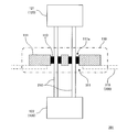
- FIG. 1 is a schematic cross-sectional view showing an example of the configuration of the first unit.
- the partition wall 310 and the conductive member 210 of the airtight container 300 to which the first unit is attached are drawn by broken lines.
- the airtight container 300 and the conductive member 210 are not included in the constituent members of the first unit.
- the first unit 101 illustrated in FIG. 1 is a signal or fluid via a conductive member 210 which is a member constituting a signal or fluid passage between the inside and the outside of the airtight container 300 while maintaining the airtightness of the airtight container 300. Can be exchanged.
- the first unit 101 includes a sealing portion 110 (a portion surrounded by a thick alternate long and short dash line) and a connecting portion 120.
- the sealing portion 110 includes a first sealing member 111 which is a member having a shape capable of covering the first hole 311 which is a through hole formed in the partition wall 310 of the airtight container 300.
- the first sealing member 111 illustrated in FIG. 1 is a plate-shaped member made of aluminum (a portion provided with a diagonal line rising to the right).
- the first sealing member 111 is fixed to the partition wall 310 of the airtight container 300 by a bolt (not shown) so as to cover the first hole 311 to close the first hole 311.
- the second hole 111a which is a through hole formed so as to communicate with the first hole 311, is formed in the first sealing member 111.
- the first hole 311 is formed in the partition wall 310 of the airtight container 300 so as to have a size and a shape capable of communicating with all the second holes 111a.
- the connection unit 120 illustrated in FIG. 1 includes an external connector 121 and an internal connector 122 as the above-mentioned connectors.
- the external connector 121 is connected to the conductive member 210 at the end of the conductive member 210 located outside the airtight container 300, and is provided with a conductive member (not shown) provided by another device or equipment (not shown) outside the airtight container 300.
- a conductive member not shown
- it is a connector configured to be able to send and receive signals and / or fluids between a signal line or a pipe through which a fluid flows inside a sensor) and a conductive member 210.
- the internal connector 122 is connected to the conductive member 210 at the end of the conductive member 210 located inside the airtight container 300, and is provided with other equipment or equipment (not shown) inside the airtight container 300. It is a connector configured to be able to send and receive signals and / or fluids between a member (for example, a signal line provided in a sensor or a pipe through which a fluid flows inside) and a conductive member 210.
- the external connector 121 and the internal connector 122 are commercially available connectors having terminals that can be electrically connected to each of the conductive members 210 that are electric wires.
- the number, size, shape, etc. of the second hole 111a formed in the first sealing member 111 are adjusted according to the number, thickness, and shape of the conductive members 210 inserted through the second hole 111a. Designed accordingly.
- two second holes 111a are arranged at positions that are easily reachable from the surroundings at a sufficient distance from each other. As a result, the work of filling the sealing material between the inner peripheral surface of the second hole 111a and the conductive member 210 can be facilitated (details will be described later).
- first assembly the airtight connection assembly according to the first embodiment of the present invention (hereinafter, may be referred to as “first assembly”) will be described with reference to the drawings.
- the present invention relates not only to the unit of the present invention having the above-mentioned characteristics, but also to an assembly for airtight connection.
- the "assembly for airtight connection” is provided with the unit of the present invention, and enables transmission and reception of electric signals and the like between the inside and the outside of the airtight container while maintaining the airtightness of the airtight container in which the electric equipment and the like are housed. It is an assembly.
- the first assembly is an assembly for airtight connection including the above-mentioned first unit and a conductive member, and the sealing portion further provided with a sealing material. Further, the conductive member is individually inserted into the second hole, and a sealing material is filled between the conductive member and the inner peripheral surface of the second hole. In addition, the connector is connected to one or both ends of the conductive member. Since the first unit has already been described in detail in the above-described description of the first unit, the description thereof will be omitted here.
- the conductive member is a member that constitutes a signal and / or fluid passage.
- the signal transmitted by the conductive member is not particularly limited, and for example, not only an electric signal (for example, a detection signal output from a sensor or the like and an instruction signal output from a control device or the like, but also a power output from a power supply device or the like) is used. Including) or a signal such as an optical signal.
- the conductive member is an electric wire, and the electric wire may be covered with, for example, an insulator and / or a protective coating.
- the signal is an optical signal
- the conductive member is an optical fiber, and the optical fiber may be, for example, an optical cable covered with a protective coating or the like.
- the fluid flowing through the passage formed by the conductive member is also not particularly limited, and may be a fluid such as a gas or a liquid, for example.
- the conductive member may be, for example, a tubular member such as a tube or a pipe in which a space serving as a flow path for the fluid flows is formed inside.
- tubular members such as tubes or pipes do not necessarily have to be covered with an insulator and / or a protective coating.
- the number of conductive members included in the first assembly may be one or a plurality (that is, two or more).
- all of those flowing through the plurality of passages composed of the plurality of conductive members may be electric signals, all may be optical signals, and all may be optical signals.
- the sealing material is not particularly limited as long as it is a material capable of staying between the conductive member and the inner peripheral surface of the second hole to maintain airtightness in the usage environment of the airtight container to which the first assembly is attached. ..
- airtight as used herein is not necessarily limited to a state in which gas leakage is completely prevented, and gas leakage is prevented to the extent required in the application of an airtight container to which the first assembly is attached. It is a concept that includes the state of being present.
- the encapsulant as described above include polymer organic materials such as rubber such as silicon sealant and resin such as epoxy resin, and ceramic materials such as glass.
- the polymer organic material as described above may be room temperature curable, thermosetting or thermoplastic as long as it can withstand the usage environment in the application of the airtight container to which the first assembly is attached. Therefore, the material constituting the conductive member and the first sealing member needs to be able to withstand the conditions at the time of filling and / or curing of the sealing material.
- the sealing material may be a member made of a solid such as a grommet, which is preformed so as to follow the shape of the second hole and has a through hole through which the conductive member is inserted.
- the sealing material is not sufficiently filled between the plurality of conductive members, so that the airtightness is sufficiently improved by filling the sealing material. There is a risk that it cannot be increased. Therefore, in the first assembly, the conductive members are individually inserted into the second holes as described above. That is, one conductive member is inserted into one second hole, and a plurality of conductive members are not inserted into one second hole.
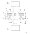
- FIG. 2 is a schematic cross-sectional view showing an example of the configuration of the first assembly.
- the partition wall 310 of the airtight container 300 to which the first assembly is attached is drawn by a broken line.
- the airtight container 300 is not included in the components of the first assembly.
- the first assembly 201 illustrated in FIG. 2 is an airtight connection assembly including two conductive members 210, a sealing portion 110 (a portion surrounded by a thick alternate long and short dash line), and a connecting portion 120.
- the first assembly 201 is an assembly for airtight connection including the above-mentioned first unit 101 and two conductive members 210, and the sealing portion 110 further includes a sealing material 113.
- the two conductive members 210 are individually inserted into the second hole 111a, and a sealing material 113 is filled between the individual conductive members 210 and the inner peripheral surface of the second hole 111a.
- An external connector 121 and an internal connector 122 are connected to both ends of the conductive member 210, respectively.
- the conductive member 210 is an electric wire that transmits an electric signal, and the electric wire is covered with a protective coating made of an insulator.
- the sealing portion 110 includes a first sealing member 111 and a sealing material 113 which are members having a shape capable of covering the first hole 311 which is a through hole formed in the partition wall 310 of the airtight container 300.
- the first sealing member 111 is a plate-shaped member made of aluminum (a portion shaded to the right), and the sealing member 113 is a room temperature curable silicone sealant (black-painted portion).
- 201 is drawn.
- the first hole 311 is formed in the partition wall 310 of the airtight container 300 so as to have a size and a shape capable of communicating with all the second holes 111a.
- the first sealing member 111 is fixed to the partition wall 310 of the airtight container 300 so as to cover the first hole 311.
- the two holes 111a are formed in the first sealing member 111, and the conductive member 210 is individually inserted into the second hole 111a and sealed between the conductive member 210 and the inner peripheral surface of the second hole 111a.
- Each of the materials 113 is filled.
- the two second holes 111a illustrated in FIG. 2 are arranged at positions that are easily reachable from the surroundings with a sufficient distance from each other. As a result, as described above, the work of filling the sealing material 113 between the inner peripheral surface of the second hole 111a and the conductive member 210 can be facilitated.
- Airtight Container an airtight container according to the first embodiment of the present invention (hereinafter, may be referred to as a “first container”) will be described with reference to the drawings.
- the present invention relates not only to the unit of the present invention and the assembly of the present invention having the characteristics described above, but also to an airtight container provided with the assembly of the present invention.
- the first container is an airtight container provided with the above-mentioned first assembly. Since the details of the first assembly have already been described in the above description of the first assembly, the description thereof will be omitted here.
- the size and shape of the airtight container that constitutes the first container, the material that constitutes the partition wall, and the like, the configuration of the airtight container are, for example, the properties of the equipment and / or equipment housed inside the airtight container, the properties of the fluid such as gas, and the airtightness. It can be appropriately selected according to the usage environment and the like in the application of the container.
- the first sealing member included in the first assembly covers the first hole, which is a through hole formed in the partition wall of the first container, so that the first hole is closed. Further, a conductive member inserted into the first hole through the second hole, which is a through hole formed in the first sealing member, extends from the inside to the outside of the first container.
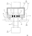
- FIG. 3 is a schematic cross-sectional view showing an example of the configuration of the first container.
- the first container 301 illustrated in FIG. 3 is an airtight container including the first assembly 201.
- the first assembly 201 included in the first container 301 has the same configuration as the first assembly 201 shown in FIG. 2, except that it does not include an internal connector.
- the first hole 311 which is a through hole is formed in the partition wall 310, and the first hole 311 is formed by the first sealing member 111 included in the sealing portion 110 included in the first assembly 201. Is blocked.
- the conductive member 210 inserted into the first hole 311 via the second hole 111a formed in the first sealing member 111 extends from the inside to the outside of the first container 301.
- the sensor 420 is housed inside the first container 301 (see the ellipse drawn by the broken line), and the conductive member 210 is, for example, an electric wire as a passage for transmitting a detection signal output from the sensor 420.
- the conductive member 210 may be a power line that supplies electric power to the equipment or equipment housed inside the first container 301, or the tank and the first container 301 housed inside the first container 301. It may be a pipe such as a tube or a pipe that exchanges fluid with the outside.
- the first assembly 201 included in the first container 301 illustrated in FIG. 3 does not have an internal connector. Therefore, in the example shown in FIG. 3, the signal lines 421 and 422 included in the sensor 420 and the two conductive members 210 included in the first assembly 201 are directly connected to each other. However, when the first assembly 201 included in the first container 301 includes an internal connector, these can be easily connected by the internal connector.
- first vaporizer the vaporizer according to the first embodiment of the present invention
- the present invention relates not only to the unit of the present invention, the assembly of the present invention and the container of the present invention having the above-mentioned characteristics, but also to a vaporizer provided with the container of the present invention.
- the first vaporizer is a vaporizer including the above-mentioned first container, a tank housed inside the first container, a sensor and / or a heater. Since the details of the first container have already been described in the above description of the first container, the description thereof will be omitted here.
- the tank is a container that houses the gas to be supplied by the first vaporizer and / or the gas raw material that is the substance that is the source of the gas, and is generated inside the gas and / or the tank.
- the gas is led out from the inside of the first container to the outside.
- the sensor is configured to output a detection signal corresponding to the amount and / or state of the gas contained inside the tank and / or the gas raw material which is the substance that is the source of the gas.
- the amount of gas and / or the gas raw material means, for example, the mass, volume and liquid level of the gas and / or the gas raw material (when the gas raw material is a liquid) and the like.
- the state of the gas and / or the gas raw material means, for example, the temperature, pressure, concentration of a specific component, etc. of the gas and / or the gas raw material.
- the heater is configured to be supplied with electric power to heat the above gas raw material.
- a heater include a resistance heating type heater, a dielectric heating type heater, a microwave heating type heater, an induction heating type heater, and the like.
- the heater is a resistance heating type heater.
- the first vaporizer is configured such that gas and / or detection signals and / or power are exchanged between the inside and outside of the first container via a conductive member included in the first assembly. ..
- the first vaporizer In the first vaporizer, at least one of the above-mentioned gas, detection signal, and electric power is transferred between the inside and the outside of the first container without going through the conductive member included in the first assembly. It may be configured in.
- the first vaporizer may be provided with a lead-out pipe as a flow path configured to lead out the gas from the inside of the tank to the outside of the airtight container separately from the conductive member.
- the configuration of the lead-out pipe is not particularly limited as long as the gas can be led out from the inside of the tank to the outside of the airtight container, and depends on, for example, the nature of the gas and the usage environment in the application of the vaporizer. It can be selected as appropriate.
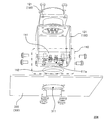
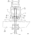
- FIG. 4 is a schematic diagram showing an example of the configuration of the first vaporizer.
- the first vaporizer 401 illustrated in FIG. 4 is a first container for the above-mentioned first container 301, a tank 410 housed inside the first container 301, a sensor 420, and a gas generated inside the tank 410.
- a lead-out pipe 430 that leads from the inside of the 301 to the outside is provided.
- the sensor 420 uses the temperature (T) of the gas raw material (substance that is the source of gas) stored inside the tank 410, the concentration (C) of a specific component in the gas raw material, and the gas. It is configured to detect the pressure (P) of the gas generated from the raw material.
- the heater is not shown.
- the first vaporizer 401 includes an introduction pipe 440 that introduces a carrier gas below the liquid level of the gas raw material stored inside the tank 410.
- the first vaporizer 401 includes a flow rate control device 510 that controls the flow rate of the carrier gas introduced into the tank 410, and a gas that is led out from the inside of the first container 301 to the outside by the lead-out pipe 430.
- a flow meter 520 for measuring the flow rate of a mixed gas of a gas generated from a raw material and a carrier gas is provided.
- the first vaporizer 401 having the above configuration keeps the temperature of the gas raw material stored inside the tank 410 and the pressure of the gas generated from the gas raw material constant, and the gas stored inside the tank 410. It is configured to introduce the carrier gas below the liquid level of the raw material at a predetermined flow rate. Then, the first vaporizer 401 guides the mixed gas of the gas generated from the gas raw material and the carrier gas from the exhaust port of the tank 410 to the outside of the first container 301 through the outlet pipe 430. That is, the first vaporizer 401 is a bubbling type vaporizer.
- the first vaporizer 401 is generated from the gas raw material by subtracting the carrier gas flow rate Q1 measured by the flow rate control device 510 from the mixed gas flow rate Q2 measured by the flow meter 520.
- the temperature (T) of the gas raw material and a specific component in the gas raw material In the process of supplying the gas generated from the gas raw material at a predetermined flow rate as described above to a predetermined supply destination (chamber 530 in FIG. 4), the temperature (T) of the gas raw material and a specific component in the gas raw material.
- a detection signal corresponding to the concentration (C) of the gas and the pressure (P) of the gas generated from the gas raw material is output from the sensor 420.
- These detection signals are transmitted from the inside to the outside of the first container 301 by the first assembly 201 included in the first container 301 while maintaining the airtightness of the first container 301, and are not shown in the first assembly 201. It is transmitted to a control device (not shown) or the like via a plug 450 connected to an external connector and a cable 460 connected to the plug 450, and is used for controlling the flow rate of gas.
- the conductive member is configured as a signal line (electric wire) for transmitting the detection signal output from the sensor from the inside to the outside.
- the conductive member is a member that constitutes a signal or fluid passage.
- the signal transmitted by the conductive member is not limited to an electric signal, and may be a signal such as an optical signal.
- the fluid flowing through the passage formed by the conductive member is also not particularly limited, and may be a fluid such as a gas or a liquid.
- the conductive member may be, for example, an electric wire or an optical fiber, or may be, for example, a tubular member such as a tube or a pipe in which a space serving as a flow path for a fluid flows is formed inside.
- the lead-out pipe 430 and the introduction pipe 440 included in the first vaporizer 401 illustrated in FIG. 4 are arranged so as to cover a through hole (not shown) formed in the partition wall 310 of the first container 301. Gas and gas raw materials may be exchanged between the inside and the outside of the first container 301 via one assembly 201.
- first method a method for manufacturing an assembly for airtight connection according to the first embodiment of the present invention will be referred to with reference to the drawings (hereinafter, may be referred to as "first method"). Will be described.
- the present invention relates not only to the unit of the present invention, the assembly of the present invention, the container of the present invention and the vaporizer of the present invention having the characteristics described above, but also to the method for manufacturing the assembly of the present invention. Also related.
- the first method is the method for manufacturing the first assembly described above. Since the details of the first assembly have already been described in the above description of the first assembly, the description thereof will be omitted here. Further, the first method includes each step listed below.
- Step A Connecting the connector to at least one end of the conducting member.
- Step B The conductive member is individually inserted into the second hole, which is a through hole formed in the first sealing member.
- Step C Filling a sealing material between the inner peripheral surface of the second hole and the conductive member.
- Step D Inserting the conductive member into the first hole, which is a through hole formed in the partition wall of the airtight container.
- Step E Fixing the first sealing member at a predetermined position on the partition wall of the airtight container and closing the first hole with the first sealing member.
- FIG. 5 is a flowchart showing an example of the flow of each process included in the first method.
- each step is executed in the order of S10, S20, S30, S40 and S50. That is, in the first method illustrated in FIG. 5, each of the above-mentioned steps is executed in the order of "step A-> step B-> step C-> step D-> step E".
- the execution order of the steps A to E included in the first method does not necessarily have to be as described above.
- the airtight container to which the first assembly is applied the configuration of the first assembly, and the periphery of the airtight container.
- the execution order of each process can be changed as appropriate according to the environment and the like.
- the first assembly 201 illustrated in FIG. 2 can be assembled from the first unit 101 illustrated in FIG. 1 by the procedure shown below.
- the external connector 121 is connected to one end of the two conductive members 210.
- each of the conductive members 210 connected to the external connector 121 is individually inserted into the two second holes 111a formed in the first sealing member 111 from the end opposite to the external connector 121.
- the sealing material 113 is filled between the inner peripheral surface of each second hole 111a and the conductive member 210 and cured.
- the end of the conductive member 210 opposite to the external connector 121 which constitutes an assembly composed of the external connector 121, the conductive member 210, and the first sealing member 111 assembled in this manner, is attached to the outside of the airtight container 300. From the side, it is inserted into the first hole 311 formed in the partition wall 310 of the airtight container 300.
- first sealing member 111 is fixed at a predetermined position on the partition wall 310 of the airtight container 300 by a bolt (not shown), and the first hole 311 is covered and closed by the first sealing member 111.
- the end of the conductive member 210 on the opposite side of the external connector 121 is connected to a device or equipment (not shown) such as a sensor arranged inside the airtight container 300.
- the connection may be a direct connection between a terminal or the like of the device or equipment and the conductive member 210, or may be a connection via an internal connector 122 included in the first unit 101 illustrated in FIG. Good.
- the conductive member 210 and the internal connector 122 are used before the first sealing member 111 is fixed at a predetermined position on the partition wall 310 of the airtight container 300. May be connected with.
- the sealing portion and the connecting portion can be configured by easily available general-purpose constituent members such as a commercially available metal plate and a connector.
- an airtight connection assembly capable of sending and receiving electric signals and the like between the inside and the outside of the airtight container while maintaining the airtightness of the airtight container by a simple configuration. Can be done.
- the first assembly is an assembly for airtight connection including the first unit and the conductive member, and the sealing portion further includes the sealing material.
- the conductive member is individually inserted into the second hole, and the conductive member is provided.
- a sealing material is filled between the hole and the inner peripheral surface of the second hole, and the connector is connected to one or both ends of the conductive member.
- the first container is an airtight container including the first assembly, the first hole is closed by the first sealing member, and the first hole is formed through the second hole formed in the first sealing member.
- a conductive member inserted through the hole extends from the inside to the outside of the first container.
- the first vaporizer is provided with a first container.
- a first container As a result, as already described in the explanation regarding the first container, it is possible to maintain the airtightness of the first container by a simple configuration while enabling the exchange of electric signals and the like between the inside and the outside of the first container. it can. Therefore, according to the first vaporizer, for example, gas leaks from the tank housed inside the first container to the outside of the first container and / or foreign matter (for example, foreign matter from the outside of the first container to the inside of the tank). Since it is possible to reduce the intrusion of ambient gas and the like), it is possible to provide a vaporizer having high safety with a simple configuration.
- the first method which is a method for manufacturing the first assembly having the above configuration
- the connection between the conductive member and the connector step A
- the insertion of the conductive member into the second hole of the first sealing member step B
- filling of a sealing material between the inner peripheral surface of the second hole and the conductive member step C
- insertion of the conductive member into the first hole of the airtight container step D
- the airtight container step E
- the closing of the first hole (step E) by fixing the first sealing member to a predetermined position of the partition wall of the above can be performed individually. Therefore, according to the first method, a first assembly capable of achieving the above-mentioned effects can be easily manufactured by a simple and highly flexible process.
- Airtight Connection Unit an airtight connection unit according to a second embodiment of the present invention (hereinafter, may be referred to as a “second unit”) will be described with reference to the drawings.
- the airtight connection unit (unit of the present invention) according to various embodiments of the present invention including the above-mentioned first unit, easily available general-purpose constituent members such as commercially available metal plates and connectors, for example.
- the sealing portion and the connecting portion can be configured by the above.
- the connector and / or the conductive member itself connected to one or both ends of the conductive member can move flexibly.
- the work of fixing the first sealing member may be performed.
- the conductive member may be damaged due to bending or deformation, for example, when assembling to an airtight container.
- the second unit is an airtight connection unit that further includes a connecting portion including a connecting member in addition to the constituent members included in the first unit described above.
- the coupling member is a member capable of coupling at least one of the above connectors and the first sealing member to fix the positional relationship between the connector and the first sealing member.
- the connecting member As a specific configuration of the connecting member, it is possible to connect the connector and the first sealing member so as to fix the positional relationship between the at least one connector included in the connecting portion and the first sealing member.
- the connecting member includes a connector holding member which is a member for holding the connector, and a connector supporting member which is a member for connecting the first sealing member and the connector holding member to support the connector holding member.
- the connector holding member and the connector supporting member may be configured as separate members or may be configured as an integral member.
- the conductive member inserted through the first hole which is a through hole formed in the partition wall of the airtight container, penetrates the first sealing member so that the conductive member can be further inserted.
- a second hole is formed. Then, when the first assembly is assembled from the first unit, the conductive member is individually inserted into the second hole, and the sealing material is filled between the conductive member and the inner peripheral surface of the second hole. .. Therefore, in the second unit, after the at least one connector included in the connecting portion and the first sealing member are connected by the connecting member, the sealing material between the conductive member and the inner peripheral surface of the second hole is provided. It is desirable that the connecting member has a structure that does not hinder or does not hinder the filling work of the sealing material even when filling is performed.
- the connecting member includes, for example, a pair of plate-shaped connector supporting members facing each other and a plate-shaped connector holding member connected so as to hang over one end of the pair of connector supporting members.
- the coupling member may include a plate-shaped connector holding member and a connector support member as a plurality of legs extending from the connector holding member toward the first sealing member.
- a sealing material is filled between the conductive member and the inner peripheral surface of the second hole through the space between the adjacent legs. be able to.
- the material constituting the connecting member is also not particularly limited as long as it can withstand the usage environment in the application of the airtight container to which the assembly for airtight connection composed of the second unit is attached.
- the material constituting the coupling member is a metal or resin such as aluminum and iron, or a composite material thereof.
- FIG. 6 is a schematic cross-sectional view showing an example of the configuration of the second unit.
- the second unit 102 drawn in FIG. 6 also has the first sealing member 111 fixed to the partition wall 310 of the airtight container 300 by a bolt (not shown) so as to cover the first hole 311. It is in a state of blocking the first hole 311.
- the partition wall 310 and the conductive member 210 of the airtight container 300 to which the airtight connection assembly composed of the second unit 102 is attached are drawn by broken lines.
- the second unit 102 illustrated in FIG. 6 is a member configured to connect the external connector 121 and the first sealing member 111 to fix the positional relationship between the external connector 121 and the first sealing member 111.
- a connector 130 including a connector 131 is further provided. Except for this point, the second unit 102 has the same configuration as the first unit 101 illustrated in FIG. Therefore, in the following description of the second unit 102, the above differences will be mainly described.
- the connecting member 131 included in the connecting portion 130 included in the second unit 102 is composed of a connector holding member 131a and a connector supporting member 131b (a portion provided with an oblique lattice pattern).
- the connector holding member 131a is a member for holding the external connector 121.
- the connector support member 131b is a pair of plate-shaped members facing each other, and the connector holding member 131a is coupled so as to span one end of the pair of connector support members 131b.
- the second assembly includes the above-mentioned second unit as an airtight connection unit in addition to the above-mentioned constituent members of the first assembly, and at least one connector and the first sealing member are connected by a connecting member to form a connector.
- This is an assembly for airtight connection in which the positional relationship between the first sealing member and the first sealing member is fixed. Since the specific configuration of the second unit constituting the second assembly and the joint portion included in the second unit has already been described in the above description of the second unit, the description thereof will be omitted here.
- FIG. 7 is a schematic cross-sectional view showing an example of the configuration of the second assembly.
- the connecting member 131 included in the connecting portion 130 included in the second assembly 202 includes a connector holding member 131a and a connector supporting member 131b (a portion provided with an oblique lattice pattern).
- the connector holding member 131a is a plate-shaped member for holding the external connector 121.
- the connector support member 131b is a plurality of columnar (rod-shaped) or plate-shaped members configured as legs extending from the connector holding member 131a toward the first sealing member 111.
- the connector holding member 131a is coupled so as to span one end of the plurality of connector supporting members 131b.
- the other ends of the plurality of connector support members 131b are fixed to the surface of the first sealing member 111 (the surface of the airtight container 300 opposite to the partition wall 310). As a result, the positional relationship between the external connector 121 and the first sealing member 111 is fixed. As a result, in the second assembly 202 illustrated in FIG. 7, the sealing material 113 is inserted between the conductive member 210 and the inner peripheral surface of the second hole 111a via the space between the plurality of connector support members 131b. It can be easily filled.
- the second container is an airtight connection assembly including the above-mentioned second assembly as the above-mentioned airtight connection assembly in addition to the above-mentioned components included in the first container. Since the specific configuration of the second assembly constituting the second container and the joint portion included in the second assembly has already been described in the above description of the second assembly, the description thereof will be omitted here.
- FIG. 8 is a schematic cross-sectional view showing an example of the configuration of the second container.
- the second container 302 illustrated in FIG. 8 is a member configured to connect the external connector 121 and the first sealing member 111 to fix the positional relationship between the external connector 121 and the first sealing member 111.
- a coupling portion 130 including a coupling member 131 is further provided. Except for this point, the second container 302 has the same configuration as the first container 301 illustrated in FIG. Therefore, in the following description of the second container 302, the above differences will be mainly described.
- the connecting member 131 included in the connecting portion 130 included in the second assembly 202 constituting the second container 302 is composed of the connector holding member 131a and the connector supporting member 131b (diagonal lattice pattern is applied). The part that was done).
- the connector holding member 131a is a plate-shaped member for holding the external connector 121.
- the connector support member 131b is a pair of plate-shaped members facing each other, and the connector holding member 131a is coupled so as to span one end of the pair of connector support members 131b.
- the second container 302 illustrated in FIG. 8 when assembling the second container 302 illustrated in FIG. 8, it is sealed between the conductive member 210 and the inner peripheral surface of the second hole 111a via the space between the pair of connector support members 131b.
- the material 113 can be easily filled.
- a vaporizer according to a second embodiment of the present invention (hereinafter, may be referred to as a "second vaporizer”) will be described.
- the second vaporizer is a vaporizer provided with a second container as an airtight container in place of the first container described above, in addition to the constituent members included in the first vaporizer described above. Since the details of the second container have already been described in the above description of the second container, the description and reference to the drawings are omitted here.
- the second method is a method of assembling the above-mentioned second assembly from the second unit instead of the above-mentioned first unit. That is, the airtight connection assembly manufactured by the second method is a member that connects at least one connector and the first sealing member to fix the positional relationship between the connector and the first sealing member. It further comprises a including joint. Therefore, the second method further includes the following step F in addition to the configuration provided in the first method described above.
- Step F Connecting at least one connector and the first sealing member with a connecting member to fix the positional relationship between the connector and the first sealing member.
- FIG. 9 is a flowchart showing an example of the flow of each step included in the second method.
- each step is executed in the order of S10, S20, S25, S30, S40 and S50. That is, in the second method illustrated in FIG. 9, each of the above-mentioned steps is executed in the order of "step A-> step B-> step F-> step C-> step D-> step E".
- the execution order of the steps A to E and F included in the second method does not necessarily have to be as described above.
- the execution order of each process can be appropriately changed according to the surrounding environment of the container and the like.
- the second unit in addition to the configuration provided in the first unit described above, at least one of the above connectors and the first sealing member are coupled to form the connector and the first sealing member. It is an airtight connection unit further including a connecting portion including a connecting member which is a member capable of fixing the positional relationship. Therefore, according to the second unit, the positional relationship between the connector and the first sealing member is fixed by connecting at least one connector included in the connecting portion and the first sealing member with the connecting member. Can be done. As a result, for example, even when the connector and / or the conductive member can move flexibly, the efficiency of the work of fixing the first sealing member in the process of assembling the second assembly is reduced and / or the conductive member is damaged. The problem can be reduced. Further, as a matter of course, the same effect is achieved in the process of assembling the second assembly in the manufacturing process of the second container and the second vaporizer.
- connection between the conductive member and the connector step A
- the insertion of the conductive member into the second hole of the first sealing member step B
- the connection between the connector and the first sealing member step F
- Bonding with a connecting member step F
- filling of a sealing material between the inner peripheral surface of the second hole and the conductive member step C
- insertion of the conductive member into the first hole of the airtight container step D
- the closing of the first hole step E) by fixing the first sealing member to a predetermined position on the partition wall of the airtight container can be individually executed.
- the second method it is possible to send and receive electric signals and the like between the inside and the outside of the airtight container while maintaining the airtightness of the airtight container by a simple and highly flexible process.
- a second assembly capable of achieving the above-mentioned effects can be easily manufactured.
- Airtight Connection Unit an airtight connection unit according to a third embodiment of the present invention (hereinafter, may be referred to as a “third unit”) will be described with reference to the drawings.
- the airtight container is formed on the partition wall.
- the first hole which is a through hole
- the first sealing member By covering the first hole, which is a through hole, with the first sealing member, the first hole is closed and airtightness is achieved.
- the airtight container it may be difficult to achieve sufficient airtightness by the above configuration.
- Specific examples of such a case include, for example, when the partition wall and / or the first sealing member of the airtight container does not have sufficient flatness, or for fixing the first sealing member to the partition wall of the airtight container. Examples thereof include the case where the partition wall and / or the first sealing member of the airtight container is deformed due to the stress acting together.
- the third unit is an airtight connection unit further including a second sealing member in addition to the constituent members included in the first unit or the second unit described above.
- the second sealing member surrounds the first hole in a state where the airtight connection assembly composed of the third unit is attached to the airtight container (hereinafter, may be referred to as "state A"). It is a member that can be interposed between the partition wall of the airtight container and the first sealing member.
- the second sealing member reduces gas leakage through the first hole, which is a through hole formed in the partition wall of the airtight container in the above state A, and the gap between the partition wall of the airtight container and the first sealing member. To improve the airtightness of the airtight container. Therefore, as described above, the second sealing member needs to surround the first hole in the state A and to be interposed between the partition wall of the airtight container and the first sealing member.
- the specific configuration of the second sealing member is not particularly limited, but typically, a sealing member well known in the art, such as an O-ring, packing and gasket, is second-sealed. It can be used as a stop member.
- a sealing member well known in the art such as an O-ring, packing and gasket
- the same material as the sealing material described above may be arranged so as to surround the first hole in the state A and to be interposed between the partition wall of the airtight container and the first sealing member.
- a structure such as a groove or a step is provided in the portion facing the second sealing member, and the assembly for airtight connection is assembled from the third unit.
- the positioning of the second sealing member may be facilitated in the process of performing the operation, or the deviation of the second sealing member from a predetermined position may be reduced.
- the airtightness of the airtight container may decrease due to gas leakage between the fastening member and the through hole.
- the second sealing member may be configured so as to surround not only the first hole formed in the partition wall of the airtight container in the state A but also the through hole through which the fastening member is inserted.
- the second sealing member may be configured so as to surround only the first hole formed in the partition wall of the airtight container in the state A and not surround the through hole through which the fastening member is inserted.
- a member such as a packing or a gasket may be interposed between the partition wall of the airtight container and the fastening member to reduce the decrease in the airtightness of the airtight container.
- FIG. 10 is a schematic cross-sectional view showing an example of the configuration of the third unit.
- the third unit 103 illustrated in FIG. 10 surrounds the first hole 311 formed in the partition wall 310 of the airtight container 300 in the above-mentioned state A, and is between the partition wall 310 of the airtight container 300 and the first sealing member 111.
- a second sealing member 112 is further provided so as to be interposed (a portion provided with a diagonal line downward to the right). Except for this point, the third unit 103 has the same configuration as the first unit 101 illustrated in FIG.
- the second sealing member 112 included in the third unit 103 illustrated in FIG. 10 is an O-ring.
- the third assembly includes the above-mentioned third unit as an airtight connection unit in addition to the above-mentioned components included in the first assembly or the second assembly. Further, in the third assembly, the second sealing member is arranged so as to surround the first hole in the above-mentioned state A and to intervene between the partition wall of the airtight container and the first sealing member. Since the specific configuration and arrangement of the second sealing member have already been described in the above description of the third unit, the description thereof will be omitted here.
- FIG. 11 is a schematic cross-sectional view showing an example of the configuration of the third assembly.
- the third assembly 203 illustrated in FIG. 11 in the state A, the first hole 311 formed in the partition wall 310 of the airtight container 300 is surrounded and interposed between the partition wall 310 of the airtight container 300 and the first sealing member 111.
- the second sealing member 112 is arranged so as to be (a portion provided with a diagonal line downward to the right). Except for this point, the third assembly 203 has the same configuration as the second assembly 202 illustrated in FIG. 7.
- the second sealing member 112 included in the third assembly 203 illustrated in FIG. 11 is an O-ring.
- the third container includes the above-mentioned third assembly as an assembly for airtight connection in addition to the above-mentioned components included in the first container or the second container, surrounds the first hole, and has a partition wall and a first seal of the third container.
- a second sealing member is arranged so as to be interposed between the stopping member. Since the specific configuration and arrangement of the second sealing member have already been described in the above description of the third assembly, the description thereof will be omitted here.
- FIG. 12 is a schematic cross-sectional view showing an example of the configuration of the third container.
- the third container 303 illustrated in FIG. 12 in the state A, the first hole 311 formed in the partition wall 310 of the third container 303 is surrounded and between the partition wall 310 of the third container 303 and the first sealing member 111.
- the second sealing member 112 is arranged so as to intervene in the (part provided with a diagonal line downward to the right). Except for this point, the third container 303 has the same configuration as the second container 302 illustrated in FIG.
- the second sealing member 112 included in the third assembly 203 constituting the third container 303 illustrated in FIG. 12 is an O-ring.
- a vaporizer according to a third embodiment of the present invention (hereinafter, may be referred to as a "third vaporizer”) will be described.
- the third vaporizer is a vaporizer equipped with the above-mentioned third container as an airtight container in addition to the above-mentioned constituent members of the first vaporizer or the second vaporizer. Since the details of the third container have already been described in the above-described description of the third container, the description and reference to the drawings are omitted here.
- the third method is a method of assembling the above-mentioned third assembly from the above-mentioned third unit. That is, the airtight connection assembly manufactured by the third method can surround the first hole, which is a through hole formed in the partition wall of the airtight container, and can be interposed between the partition wall and the first sealing member. A second sealing member, which is a new member, is further provided. Therefore, the third method further includes the following steps G and H in addition to the configuration provided in the first method or the second method described above.
- Step G Inserting the conductive member through the second sealing member.
- Step H The second sealing member is arranged so as to surround the first hole formed in the partition wall of the airtight container and to intervene between the partition wall and the first sealing member.
- FIG. 13 is a flowchart showing an example of the flow of each step included in the third method.
- each step is executed in the order of S10, S20, S25, S30, S35, S40, S45 and S50. That is, in the third method illustrated in FIG. 13, each of the above-mentioned steps is executed in the order of "step A-> step B-> step F-> step C-> step G-> step D-> step H-> step E".
- the execution order of the steps A to E and F to H included in the third method does not necessarily have to be as described above, and for example, the configuration of the airtight container to which the third assembly is applied and the third assembly. Further, the execution order of each process can be appropriately changed according to the surrounding environment of the airtight container and the like.
- the third unit is in a state (state) in which an airtight connection assembly composed of the third unit is attached to the airtight container in addition to the configuration provided in the first unit or the second unit described above.
- A) is an airtight connection unit further comprising a second sealing member that surrounds the first hole and is a member that can be interposed between the partition wall of the airtight container and the first sealing member. Therefore, according to the third unit, when the partition wall and / or the first sealing member of the airtight container does not have sufficient flatness as described above, or when the first sealing member is fixed to the partition wall of the airtight container.
- the airtight container provided with the third assembly which is the assembly for airtight connection composed of the third unit.
- the airtightness required in the application of the third vaporizer which is a vaporizer including the third container and / or the third container, can be sufficiently achieved.
- connection between the conductive member and the connector (step A), the insertion of the conductive member into the second hole of the first sealing member (step B), and the connection between the connector and the first sealing member.
- the third method it is possible to send and receive electric signals and the like between the inside and the outside of the airtight container while maintaining the airtightness of the airtight container by a simple and highly flexible process.
- a third assembly capable of achieving the above-mentioned effects can be easily manufactured.
- example assembly the airtight connection assembly according to the embodiment of the present invention
- FIG. 14 is a schematic exploded perspective view showing an example of the configuration of the embodiment assembly
- FIG. 15 is a schematic exploded perspective view when the embodiment assembly 204 shown in FIG. 14 is turned upside down.
- the number of the second holes 111a formed in the first sealing member 111 for inserting the conductive member is four
- the connecting portion 120 is an internal connector. It has the same configuration as the third assembly 203 shown in FIG. 11, except that the 122 is not provided.
- a part of the partition wall 310 of the airtight container 300 is also drawn for the purpose of facilitating the understanding of the configuration of the assembly of the embodiment.
- the sealing material to be filled in the second hole 111a formed in the first sealing member 111 and the conductive member to be inserted into the second hole 111a are omitted in both FIGS. 14 and 15. ..
- the embodiment assembly 204 is an airtight connection assembly including a conductive member (not shown), a sealing portion 110, and a connecting portion 120.
- the conductive member is a member that constitutes a signal or fluid passage.
- the sealing portion 110 is a plate-shaped member made of aluminum having a shape capable of covering the first hole 311 which is a through hole formed in the partition wall 310 of the airtight container 300, and the first sealing member 111 (not shown). Contains encapsulant.
- FIG. 16 shows the positional relationship between the recess formed on the surface of the first sealing member 111 included in the embodiment assembly 204 shown in FIGS. 14 and 15 facing the airtight container 300 and the second sealing member 112.
- FIGS. 14 to 16 the surface of the first sealing member 111 included in the assembly 204 facing the airtight container 300 has a circular shape corresponding to the shape of the O-ring as the second sealing member 112.
- the recess is formed. This facilitates the alignment of the O-rings when assembling the assembly 204 of the embodiment to the airtight container 300, and can prevent the O-rings from being displaced.
- connection portion 120 included in the embodiment assembly 204 does not include the internal connector but includes only the external connector 121 as the above-mentioned connector.
- the external connector 121 is a connector for electrically connecting the conductive member included in the embodiment assembly 204 and the conductive member provided in another device or equipment at the end of the conductive member on the outer side of the airtight container 300.
- the second hole 111a which is four through holes formed so as to communicate with the first hole 311 of the airtight container 300 in the state where the embodiment assembly 204 is attached to the airtight container 300 (state A), is the first. It is formed on the sealing member 111.
- Conductive members are individually inserted into these second holes 111a one by one, and a sealing material (not shown) is filled between the conductive members and the inner peripheral surface of the second hole 111a.
- a sealing material (not shown) is filled between the conductive members and the inner peripheral surface of the second hole 111a.
- the first hole 311 formed in the partition wall 310 of the airtight container 300 is surrounded by the above-mentioned state A and is interposed between the partition wall 310 of the airtight container 300 and the first sealing member 111.
- the sealing portion 110 further includes a second sealing member 112, which is a member to be arranged.
- the embodiment assembly 204 is a member configured to connect the external connector 121 and the first sealing member 111 to fix the positional relationship between the external connector 121 and the first sealing member 111.
- a coupling portion 130 including the member 131 is further provided.
- the connecting member 131 included in the connecting portion 130 included in the assembly 204 of the embodiment fixes the connector holding member, which is a plate-shaped member for holding the external connector 121, and both ends of the holding member to the first sealing member 111. It is composed of a connector support member which is a pair of plate-shaped members for the purpose, and these members are integrally formed.
- the external connector 121 is fixed and held by the connector holding member in a state where the connection terminal is inserted into the through hole formed in the plate-shaped connector holding member. That is, the external connector 121 illustrated in FIGS. 14 to 16 is a so-called "receptacle", and for example, a commercially available general-purpose receptacle can be used as the external connector 121.
- a connector selection is made compared to a conventional hermetic connector.
- the width expands.
- general purpose receptacles are generally available at low prices.
- FIG. 17 shows the first hole 311 and the first sealing member 111 in which the conductive member 210 connected to the external connector 121 included in the embodiment assembly 204 shown in FIGS. 14 to 16 is formed in the partition wall 310 of the airtight container 300. It is a schematic disassembled perspective view which shows the state which is inserted into the 2nd hole 111a formed in.
- FIG. 17 and the following description only two conductive members 210 are referred to for the purpose of making FIG. 17 easy to see and explaining the assembly procedure of the embodiment assembly 204 in an easy-to-understand manner.
- one conductive member 210 is inserted into each of the second holes 111a formed in the first sealing member 111, and the conductive member 210 is sealed between the inner peripheral surface of each second hole 111a and the conductive member 210.
- the material can be filled and sealed.
- the second hole 111a formed in the first sealing member 111 through which the conductive member 210 is not inserted remains, the second hole 111a is filled with a sealing material and sealed. Therefore, the airtightness of the airtight container 300 can be achieved.
- the conductive member 210 is connected to a predetermined terminal of the external connector 121 (step A), the conductive member 210 is inserted into the through hole formed in the coupling member 131, and the external connector 121 is inserted. It is fixed to the connecting member 131 by a fastening member.
- each of the conductive members 210 is inserted into each of the two second holes 111a formed in the first sealing member 111 (step B).
- the first sealing member 111 is fixed at a predetermined position on the side opposite to the external connector 121 of the coupling member 131 (step F).
- a room temperature curable silicone sealant as a sealing material (not shown) is filled between the inner peripheral surface of each second hole 111a and the conductive member 210 and cured (step C).
- the conductive member 210 is inserted into the O-ring as the second sealing member 112 and the first hole 311 formed in the partition wall 310 of the airtight container 300 (steps G and D). Then, in a state where the O-ring is partially fitted into the recess formed on the surface of the first sealing member 111 facing the airtight container 300 and aligned (step H), the airtight container 300 is provided with the fastening member.
- the first sealing member 111 is fixed at a predetermined position on the partition wall 310, and the first hole 311 is closed by the first sealing member 111 (step E). That is, the embodiment assembly 204 can be manufactured by the same procedure as the method for manufacturing the airtight connection assembly (third method) according to the third embodiment of the present invention described above.
- the end of the conductive member 210 on the opposite side of the external connector 121 is connected to a device or equipment (not shown) such as a sensor arranged inside the airtight container 300.
- the connection may be a connection via the internal connector 122 as in the first assembly 201 to the third assembly 203 illustrated in FIGS. 2, 7, and 11.
- the connection is a direct connection between the terminal or the like of the device or equipment and the conductive member 210 as in the first assembly 201 to the third assembly 203 exemplified in FIGS. 3, 8 and 12. May be good.
- FIG. 18 is a schematic perspective view showing a situation in which the embodiment assembly 204 shown in FIGS. 14 to 17 is attached to the airtight container 300.
- a plug 450 is connected to the external connector 121 included in the embodiment assembly 204 illustrated in FIG. 18, and a cable 460 is connected to the plug 450.
- a device or equipment such as a sensor arranged inside the airtight container 300 (not shown) and a control device or the like provided outside the airtight container 300 (not shown). Etc. can be exchanged.
- the sealing portion 110 and the connection are made by easily available general-purpose components such as a commercially available metal plate and a connector.
- the unit 120 can be configured.
- the member is arranged so as to surround the first hole 311 in the above-mentioned state A and to be interposed between the partition wall 310 of the airtight container 300 and the first sealing member 111.
- the sealing portion 110 further includes a sealing member 112. Therefore, as described above, when the partition wall 310 and / or the first sealing member 111 of the airtight container 300 does not have sufficient flatness, or when the first sealing member 111 is fixed to the partition wall 310 of the airtight container 300.
- the external connector 121 and the first sealing member 111 are connected by the coupling member 131, and the positional relationship between the external connector 121 and the first sealing member 111 is fixed. Therefore, for example, when it is difficult to fix the Example Assembly 204 to the airtight container 300 if the external connector 121 and / or the conductive member 210 can move flexibly, or when assembling to the airtight container 300, etc. Even when the conductive member 210 is damaged due to bending or deformation, problems such as a decrease in work efficiency and damage to the conductive member 210 can be reduced.
- Example Assembly 204 The effect achieved by the Example Assembly 204 as described above is similarly achieved in the airtight container to which the Example Assembly 204 is attached, the vaporizer provided with the airtight container, and the like.
Abstract
L'invention concerne un ensemble de connexion étanche à l'air comprenant : un élément de conduction qui configure un passage de signal ou de fluide ; une unité d'étanchéité qui comprend un premier élément d'étanchéité ayant une forme pour laquelle il est possible de recouvrir un premier trou formé sur une paroi de séparation d'un récipient étanche à l'air et un matériau d'étanchéité ; et une partie de connexion qui comprend un connecteur relié à l'une ou aux deux parties d'extrémité de l'élément de conduction ; un second trou qui est un trou traversant formé pour relier l'intérieur du récipient étanche à l'air et l'extérieur est formé sur le premier élément d'étanchéité, l'élément de conduction est inséré individuellement dans le second trou, et le matériau d'étanchéité est rempli entre l'élément de conduction et la paroi périphérique interne du second trou. Ceci permet de transférer des signaux électriques, etc, entre l'intérieur du récipient étanche à l'air et l'extérieur tout en maintenant l'étanchéité à l'air du récipient étanche à l'air à l'aide d'une configuration simple. Il est également possible de comprendre en outre un élément de couplage qui couple le connecteur et le premier élément d'étanchéité, fixant la relation de position du connecteur et du premier élément d'étanchéité. Il est également possible de comprendre en outre un second élément d'étanchéité qui entoure le premier trou et est interposé entre la paroi de séparation et le premier élément d'étanchéité.
Priority Applications (4)
| Application Number | Priority Date | Filing Date | Title |
|---|---|---|---|
| JP2021550598A JPWO2021065529A1 (fr) | 2019-09-30 | 2020-09-17 | |
| US17/763,314 US20220368066A1 (en) | 2019-09-30 | 2020-09-17 | Airtight connection unit, airtight connection assembly, airtight container and vaporizer, as well as production method of airtight connection assembly |
| KR1020227009432A KR20220069945A (ko) | 2019-09-30 | 2020-09-17 | 기밀 접속용 유닛, 기밀 접속용 어셈블리, 기밀 용기 및 기화기, 그리고 기밀 접속용 어셈블리의 제조 방법 |
| CN202080068914.5A CN114467364A (zh) | 2019-09-30 | 2020-09-17 | 气密连接用单元、气密连接用组件、气密容器和气化器、以及气密连接用组件的制造方法 |
Applications Claiming Priority (2)
| Application Number | Priority Date | Filing Date | Title |
|---|---|---|---|
| JP2019-179266 | 2019-09-30 | ||
| JP2019179266 | 2019-09-30 |
Publications (1)
| Publication Number | Publication Date |
|---|---|
| WO2021065529A1 true WO2021065529A1 (fr) | 2021-04-08 |
Family
ID=75338017
Family Applications (1)
| Application Number | Title | Priority Date | Filing Date |
|---|---|---|---|
| PCT/JP2020/035184 WO2021065529A1 (fr) | 2019-09-30 | 2020-09-17 | Unité de connexion étanche à l'air, ensemble de connexion étanche à l'air, récipient étanche à l'air et vaporisateur, ainsi que procédé de fabrication d'ensemble de connexion étanche à l'air |
Country Status (5)
| Country | Link |
|---|---|
| US (1) | US20220368066A1 (fr) |
| JP (1) | JPWO2021065529A1 (fr) |
| KR (1) | KR20220069945A (fr) |
| CN (1) | CN114467364A (fr) |
| WO (1) | WO2021065529A1 (fr) |
Cited By (1)
| Publication number | Priority date | Publication date | Assignee | Title |
|---|---|---|---|---|
| TWI819451B (zh) * | 2021-12-29 | 2023-10-21 | 唐虞企業股份有限公司 | 連接器總成及其母端連接器與公端連接器 |
Citations (7)
| Publication number | Priority date | Publication date | Assignee | Title |
|---|---|---|---|---|
| US4670623A (en) * | 1984-09-10 | 1987-06-02 | Walter Becker Gmbh | Edifice for confinement of equipment in mines and the like |
| JPS63211577A (ja) * | 1987-02-26 | 1988-09-02 | 株式会社デンソー | 燃料タンク用コネクタ |
| JPH0617780A (ja) * | 1992-07-01 | 1994-01-25 | Ubukata Seisakusho:Kk | 密閉形電動圧縮機 |
| US20060222507A1 (en) * | 2003-12-30 | 2006-10-05 | Nagaraj Jayanth | Compressor protection and diagnostic system |
| JP2009199787A (ja) * | 2008-02-20 | 2009-09-03 | Casio Comput Co Ltd | 発電装置、その制御装置、動作方法及び電子機器 |
| US20140138920A1 (en) * | 2012-11-21 | 2014-05-22 | National Oilwell Varco, L. P. | Sealing system |
| JP2015528630A (ja) * | 2012-08-08 | 2015-09-28 | エマソン エレクトリック コー. | 完全に絶縁された直接ワイヤ接続を備える気密端子 |
Family Cites Families (7)
| Publication number | Priority date | Publication date | Assignee | Title |
|---|---|---|---|---|
| JPS57211255A (en) | 1981-06-22 | 1982-12-25 | Nec Home Electronics Ltd | Manufacture of airtight terminal |
| US5101710A (en) | 1990-05-14 | 1992-04-07 | Bebco Industries, Inc. | Control apparatus or system for purged and pressurized enclosures for electrical equipment |
| KR0149896B1 (ko) * | 1992-06-05 | 1999-10-01 | 오까다 하지마 | 금속제 격벽부재의 부재관통공의 봉지구조 |
| JP5521777B2 (ja) * | 2010-05-26 | 2014-06-18 | 住友電装株式会社 | 電線引出孔のシール構造 |
| WO2014143179A1 (fr) * | 2013-03-15 | 2014-09-18 | Emerson Electric Co. | Terminal hermétique haute pression |
| US10136535B2 (en) * | 2014-12-24 | 2018-11-20 | Medtronic, Inc. | Hermetically-sealed packages including feedthrough assemblies |
| JP2017224493A (ja) * | 2016-06-15 | 2017-12-21 | 横河電機株式会社 | ハーメチック構造および製造方法 |
-
2020
- 2020-09-17 KR KR1020227009432A patent/KR20220069945A/ko unknown
- 2020-09-17 CN CN202080068914.5A patent/CN114467364A/zh active Pending
- 2020-09-17 WO PCT/JP2020/035184 patent/WO2021065529A1/fr active Application Filing
- 2020-09-17 JP JP2021550598A patent/JPWO2021065529A1/ja active Pending
- 2020-09-17 US US17/763,314 patent/US20220368066A1/en active Pending
Patent Citations (7)
| Publication number | Priority date | Publication date | Assignee | Title |
|---|---|---|---|---|
| US4670623A (en) * | 1984-09-10 | 1987-06-02 | Walter Becker Gmbh | Edifice for confinement of equipment in mines and the like |
| JPS63211577A (ja) * | 1987-02-26 | 1988-09-02 | 株式会社デンソー | 燃料タンク用コネクタ |
| JPH0617780A (ja) * | 1992-07-01 | 1994-01-25 | Ubukata Seisakusho:Kk | 密閉形電動圧縮機 |
| US20060222507A1 (en) * | 2003-12-30 | 2006-10-05 | Nagaraj Jayanth | Compressor protection and diagnostic system |
| JP2009199787A (ja) * | 2008-02-20 | 2009-09-03 | Casio Comput Co Ltd | 発電装置、その制御装置、動作方法及び電子機器 |
| JP2015528630A (ja) * | 2012-08-08 | 2015-09-28 | エマソン エレクトリック コー. | 完全に絶縁された直接ワイヤ接続を備える気密端子 |
| US20140138920A1 (en) * | 2012-11-21 | 2014-05-22 | National Oilwell Varco, L. P. | Sealing system |
Cited By (1)
| Publication number | Priority date | Publication date | Assignee | Title |
|---|---|---|---|---|
| TWI819451B (zh) * | 2021-12-29 | 2023-10-21 | 唐虞企業股份有限公司 | 連接器總成及其母端連接器與公端連接器 |
Also Published As
| Publication number | Publication date |
|---|---|
| US20220368066A1 (en) | 2022-11-17 |
| JPWO2021065529A1 (fr) | 2021-04-08 |
| CN114467364A (zh) | 2022-05-10 |
| KR20220069945A (ko) | 2022-05-27 |
Similar Documents
| Publication | Publication Date | Title |
|---|---|---|
| RU2398333C2 (ru) | Герметичный для текучей среды ввод проводов | |
| JP4364276B2 (ja) | 海底中継装置のフィードスルー及び海底中継装置 | |
| US8671753B2 (en) | Cable harness for a sensor | |
| KR101766144B1 (ko) | 온도센서 일체형 압력센서 | |
| JP2009030771A (ja) | 加熱・保温チューブを有する装置 | |
| WO2021065529A1 (fr) | Unité de connexion étanche à l'air, ensemble de connexion étanche à l'air, récipient étanche à l'air et vaporisateur, ainsi que procédé de fabrication d'ensemble de connexion étanche à l'air | |
| BR112018011891B1 (pt) | Sistemas de conexão elétrica modular para aplicações de contenção de pressão e para aplicações na cabeça de poço | |
| CN1182479A (zh) | 带高压隔离体装配件的压力变送器 | |
| US20100227492A1 (en) | Current connection apparatus for tanks | |
| BR112018011871B1 (pt) | Penetrador elétrico e montagems de passagem de aimentação resistentes ao fogo | |
| RU2622033C1 (ru) | Проходной узел передачи электроэнергии в низкотемпературную систему | |
| KR20100100709A (ko) | 전력 연결 장치 | |
| JP2020025025A (ja) | 防爆構造 | |
| US7244895B1 (en) | Electrical feedthrough for varied environmental conditions | |
| JP2013254688A (ja) | コネクタ | |
| CN102570142B (zh) | 电子设备保持用插座以及火焰传感器 | |
| CN104870989A (zh) | 用于内燃机的进气传感器 | |
| KR102437952B1 (ko) | 압력센서 | |
| JP2007311351A (ja) | 2つのハーフシェルから形成されたゲルシールを備えたコネクタ部材 | |
| WO2006124409A2 (fr) | Appareil et procede de connexion de cable | |
| CN211504538U (zh) | 一种电子设备及气密性测试系统 | |
| KR101691469B1 (ko) | 기밀 방식으로 하우징 벽을 통해 도체를 유도하기 위한 장치 | |
| US20180351285A1 (en) | Electrical connection assembly for subsea applications | |
| CN108432056B (zh) | 用于电连接器的灌注化合物腔室设计 | |
| WO2024083144A1 (fr) | Dispositif de refroidissement de liquide et bloc-batterie |
Legal Events
| Date | Code | Title | Description |
|---|---|---|---|
| 121 | Ep: the epo has been informed by wipo that ep was designated in this application |
Ref document number: 20871498 Country of ref document: EP Kind code of ref document: A1 |
|
| ENP | Entry into the national phase |
Ref document number: 2021550598 Country of ref document: JP Kind code of ref document: A |
|
| NENP | Non-entry into the national phase |
Ref country code: DE |
|
| 122 | Ep: pct application non-entry in european phase |
Ref document number: 20871498 Country of ref document: EP Kind code of ref document: A1 |