WO2021065408A1 - 操舵制御装置及び操舵制御方法 - Google Patents
操舵制御装置及び操舵制御方法 Download PDFInfo
- Publication number
- WO2021065408A1 WO2021065408A1 PCT/JP2020/034275 JP2020034275W WO2021065408A1 WO 2021065408 A1 WO2021065408 A1 WO 2021065408A1 JP 2020034275 W JP2020034275 W JP 2020034275W WO 2021065408 A1 WO2021065408 A1 WO 2021065408A1
- Authority
- WO
- WIPO (PCT)
- Prior art keywords
- steering
- gain
- steering angle
- wheel
- angle
- Prior art date
- Legal status (The legal status is an assumption and is not a legal conclusion. Google has not performed a legal analysis and makes no representation as to the accuracy of the status listed.)
- Ceased
Links
Images


Classifications
-
- B—PERFORMING OPERATIONS; TRANSPORTING
- B62—LAND VEHICLES FOR TRAVELLING OTHERWISE THAN ON RAILS
- B62D—MOTOR VEHICLES; TRAILERS
- B62D6/00—Arrangements for automatically controlling steering depending on driving conditions sensed and responded to, e.g. control circuits
- B62D6/002—Arrangements for automatically controlling steering depending on driving conditions sensed and responded to, e.g. control circuits computing target steering angles for front or rear wheels
-
- B—PERFORMING OPERATIONS; TRANSPORTING
- B62—LAND VEHICLES FOR TRAVELLING OTHERWISE THAN ON RAILS
- B62D—MOTOR VEHICLES; TRAILERS
- B62D5/00—Power-assisted or power-driven steering
- B62D5/04—Power-assisted or power-driven steering electrical, e.g. using an electric servo-motor connected to, or forming part of, the steering gear
- B62D5/0457—Power-assisted or power-driven steering electrical, e.g. using an electric servo-motor connected to, or forming part of, the steering gear characterised by control features of the drive means as such
-
- B—PERFORMING OPERATIONS; TRANSPORTING
- B62—LAND VEHICLES FOR TRAVELLING OTHERWISE THAN ON RAILS
- B62D—MOTOR VEHICLES; TRAILERS
- B62D15/00—Steering not otherwise provided for
- B62D15/02—Steering position indicators ; Steering position determination; Steering aids
- B62D15/021—Determination of steering angle
-
- B—PERFORMING OPERATIONS; TRANSPORTING
- B62—LAND VEHICLES FOR TRAVELLING OTHERWISE THAN ON RAILS
- B62D—MOTOR VEHICLES; TRAILERS
- B62D15/00—Steering not otherwise provided for
- B62D15/02—Steering position indicators ; Steering position determination; Steering aids
- B62D15/027—Parking aids, e.g. instruction means
-
- B—PERFORMING OPERATIONS; TRANSPORTING
- B62—LAND VEHICLES FOR TRAVELLING OTHERWISE THAN ON RAILS
- B62D—MOTOR VEHICLES; TRAILERS
- B62D6/00—Arrangements for automatically controlling steering depending on driving conditions sensed and responded to, e.g. control circuits
- B62D6/02—Arrangements for automatically controlling steering depending on driving conditions sensed and responded to, e.g. control circuits responsive only to vehicle speed
Definitions
- the present invention relates to a steering control device and a steering control method.
- the steering angle of the steering wheels is controlled according to the vehicle conditions in response to the driver's steering operation.
- the steering control device is provided with a variable steering mechanism that changes the gear ratio of the steering.
- Patent Document 1 and Patent Document 2 there are, for example, Patent Document 1 and Patent Document 2.
- the gear ratio Ga1 at the time of turning or the gear ratio Ga2 at the time of turning back is selected according to the turning direction of the steering wheel.
- the gear ratio Gb1 corresponding to the vehicle speed V is determined by the speed-gear ratio map
- the gear ratio gain Gb2 corresponding to the vehicle speed V is determined by the steering angle speed-gear ratio gain map
- the gear ratio Gb1 is set to the gear.
- the gear ratio Ga1 at the time of addition is calculated by multiplying the specific gain Gb2.
- the gear ratio Gb1 is set high so that the actual steering angle by the steering wheels can be largely cut even if the steering angle by the steering operation is small, and in the case of sudden steering, the gear ratio gain Gb2 Is lower than 1 to prevent a delay in following the steering operation.
- a gear ratio Ga2 different from the gear ratio Ga1 at the time of turning back is selected so that the steering is positioned at the neutral position.
- An object of the present invention is to provide a steering control device and a steering control method capable of reducing the driving load of a driver during low-speed operation.
- the present invention provides steering equipped with a calculation device that drives a steering wheel actuator to change the steering angle of the steering wheel based on the amount of steering operation and calculates the control amount of the steering wheel actuator.
- a control device the arithmetic device controls the steering wheel actuator by a first gain in which the ratio of the actual steering angle of the steering wheel to the steering steering angle changes at the turning of the steering, and the steering is turned off.
- the return is characterized in that the steering wheel actuator is controlled by a second gain different from the first gain.
- the present invention is a steering control method for steering a steering wheel by controlling a steering wheel actuator based on a steering operation amount, and when the steering is cut, the actual steering angle of the steering wheel with respect to the steering steering angle.
- the steering wheel is steered by the first gain in which the ratio of the above changes, and the steering wheel is steered by a second gain different from the first gain when the steering is turned back.
- the various components of the present invention do not necessarily have to be independent of each other, and one component is composed of a plurality of members, a plurality of components are composed of one member, and a certain component is different. It is allowed that a part of one component overlaps with a part of another component.
- a steer-by-wire system having no mechanical connection between the steering wheel and the tire will be described as an example.
- the steer-by-wire system can independently control the steering amount and the change in the turning angle of the tire by steering.
- FIG. 1 is a schematic configuration diagram of a vehicle 1 equipped with a steering control device 2 in this embodiment.
- the vehicle 1 includes a steering wheel 3 operated by a driver, a steering angle sensor 4 that detects the steering angle of the steering wheel 3, a steering torque sensor 5 that detects the steering torque input to the steering wheel 3, and actual wheels 11.
- the actual steering angle control unit 6 that controls the steering angle
- the steering wheel actuator 7 that is controlled by the actual steering angle control unit 6 to change the steering angle of the wheels 11 (right front wheel 11FR, left front wheel 11FL), and the reaction force due to a step or the like.
- a pseudo steering reaction force generator 8 that generates a pseudo reaction force to transmit a pseudo reaction force to the steering 3, an acceleration sensor 9 that detects the acceleration of the vehicle 1, and a gyro sensor 10 that detects the inclination of the vehicle 1. I have.
- the detection signals of the acceleration sensor 9 and the gyro sensor 10 are transmitted to the steering control device 2.
- Vehicle 1 is equipped with four wheels 11 (right front wheel 11FR, left front wheel 11FL, right rear wheel 11RR, left rear wheel 11RL).
- the right front wheel 11FR and the left front wheel 11FL are steering wheels driven by the steering wheel actuator 7 to change the traveling direction of the vehicle 1.
- each of the four wheels is provided with a wheel speed sensor 12 (right front wheel speed sensor 12FR, left front wheel speed sensor 12FL, right rear wheel speed sensor 12RR, left rear wheel speed sensor 12RL).
- an actual steering angle sensor 13 that detects the actual steering angle of the wheels 11 from the operating status of the steering wheel actuator 7 is provided. It is equipped.
- the steering wheel actuator 7 drives the steering wheel based on the amount of operation of the steering 3, and changes the steering angle of the steering wheel.
- the control amount of the steering wheel actuator 7 that drives the steering wheel is calculated by an arithmetic unit described later.
- the detection signals of the steering angle sensor 4, the steering torque sensor 5, the actual steering angle sensor 13, the right front wheel speed sensor 12FR, the left front wheel speed sensor 12FL, the right rear wheel speed sensor 12RR, and the left rear wheel speed sensor 12RL are the communication bus lines 14. It is transmitted to the steering control device 2 via.
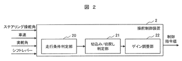
- FIG. 2 is a block diagram of the steering control device 2 according to the present embodiment.
- the steering control device 2 includes a traveling condition determination unit 20, a cut / cutback determination unit 21, and a gain adjustment unit 22.
- the steering control device 2 contains a signal related to the steering steering angle detected by the steering angle sensor 4, a signal related to the vehicle speed detected by the wheel speed sensor 12 and the acceleration sensor 9, and the wheel 11 detected by the actual steering angle sensor 13. Signals related to the vehicle's movement direction such as forward or reverse from the position of the shift lever are input.
- the steering control device 2 is a function of an ECU (Electronic Control Unit) equipped with hardware such as an arithmetic unit such as a CPU (Central Processing Unit), a main storage device, an auxiliary storage device, and a communication device. is there. Then, the arithmetic unit executes the program loaded in the main storage device while referring to the database stored in the auxiliary storage device, so that the traveling condition determination unit 20, the cut / cutback determination unit 21, and the gain adjustment unit 22 are executed. Realize each function of.
- ECU Electronic Control Unit
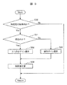
- FIG. 3 is a flowchart showing the processing of the steering control device according to the present embodiment
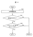
- FIG. 4 is a flowchart showing the processing of step S30 in FIG. 3
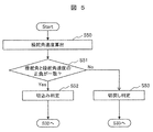
- FIG. 5 is a flowchart showing the processing of step S31 in FIG.
- step S30 the traveling condition determination unit 20 of the steering control device 2 determines whether or not the vehicle 1 is within a specific traveling condition.
- the specific driving condition means, for example, backward parking such as entering a garage.
- the process of step S30 in the traveling condition determination unit 20 will be described with reference to FIG.
- the own vehicle information such as the activation state of the own vehicle is acquired (step S40).
- step S41 it is determined whether or not the vehicle 1 is traveling at an extremely low speed from the signals detected by the wheel speed sensor 12 and the acceleration sensor 9 (step S41).
- the extremely low speed is a speed of less than 5 km / h, for example, when entering the garage.
- an acceleration sensor 9 is used in addition to the wheel speed sensor 12 to detect the speed (vehicle speed) of the vehicle 1.
- the acceleration sensor 9 is used in addition to the wheel speed sensor 12.
- step S41 when the vehicle is traveling at an extremely low speed, it is determined whether or not the shift lever has entered the R position (reverse position) even once (step S42).
- step S42 In parking patterns such as parallel parking and backward parking, the vehicle 1 often repeats forward and backward, and the shift lever enters the R (Reverse) position at least once. If the shift lever enters the R position (backward position) even once, the process proceeds to step S31.
- step S41 when the vehicle 1 is stopped or at a low speed or higher (for example, 5 km / h or higher) (No), the process returns to Start and the process is repeated.
- step S42 if the shift lever has never entered the R position (No), the process returns to Start and the process is repeated.
- the Nos in steps S41 and S42 correspond to the Nos in step S30.
- the arithmetic unit of the present embodiment controls the steering wheel actuator 7 by the first gain and the second gain, which will be described later, on condition that the vehicle speed is less than a predetermined speed and the shift lever has entered the reverse direction. There is.
- step S31 the cut / cutback determination unit 21 of the steering control device 2 determines whether or not the steering 3 is a cut.
- the process of step S31 in the cut / cutback determination unit 21 will be described with reference to FIG.
- the steering angle sensor 4 calculates the steering angular velocity of the steering 3.
- step S51 it is determined whether or not the positive and negative of the steering steering angle ⁇ and the steering steering angular velocity ⁇ ′ match.
- FIG. 6 is a diagram showing the relationship between the steering steering angle ⁇ and the steering steering angular velocity ⁇ 'according to the present embodiment.
- the intersection of the vertical axis and the horizontal axis indicates a state in which the steering wheel 3 is in a neutral position (neutral point) and the rotation of the steering wheel 3 is stopped (speed is 0). Since the steering 3 cuts to the left and right, the steering steering angle ⁇ and the steering steering angular velocity ⁇ 'change positively and negatively with the neutral point as a boundary. For example, if the steering steering angle ⁇ when the steering 3 is turned to the right is positive (the area on the right side), the steering angle ⁇ when the steering 3 is turned to the left is negative (the area on the left). Become.
- the steering angular velocity ⁇ 'when the steering wheel 3 is turned to the right side is positive (upper region)
- the steering wheel 3 is turned to the left side and the steering wheel 3 cut to the right side is turned off.
- the steering angular velocity ⁇ 'when returning is negative (lower region).
- the steering angular velocity ⁇ 'when turning back the steering 3 cut to the left side becomes positive (upper region).
- the first quadrant (upper right) and the third quadrant (lower left) are in the cut-back state of the steering wheel 3, and the second quadrant (upper left) and the fourth quadrant (lower right) are in the cut-back state of the steering wheel 3. That is, when the positive and negative of the steering steering angle ⁇ and the steering steering angle speed ⁇ 'are the same (first quadrant and third quadrant: positive or negative), the steering 3 is in the cut state, and the steering steering angle ⁇ and the steering are steered. When the positive and negative of the steering angle speed ⁇ 'do not match (second quadrant and fourth quadrant: positive or negative or negative positive), the steering 3 is in the switchback state.
- step S51 when the positive and negative of the steering steering angle ⁇ and the steering steering angular velocity ⁇ 'match (Yes), the steering 3 determines that the steering is incision (step S52), and the process proceeds to step S32.
- step S51 if the positive / negative of the steering steering angle ⁇ and the steering angular velocity ⁇ 'do not match (No), the steering 3 determines that the steering is turned back (step S53), and the process proceeds to step S33.
- the steering wheel actuator 7 is controlled by a gain (first gain) in which the ratio of the actual steering angle of the steering wheels (right front wheel 11FR, left front wheel 11FL) to the steering steering angle changes.
- the steering wheel actuator 7 is controlled by a gain (second gain) different from that of the first gain.
- step S31 when the steering wheel 3 is notched, a gain (first gain) of a continuous function in which the ratio of the actual steering angle of the steering wheel to the steering angle of the steering wheel is convex upward is selected (step S32).
- the upwardly convex continuous function is calculated based on the steering angle ⁇ and the steering angular velocity ⁇ '.
- a linear gain (second gain) is selected so as to be a function in which the ratio of the actual steering angle to the steering angle of the steering is proportional (step S33). ..
- step S34 the control amount according to each gain is calculated, the calculation result is transmitted from the steering control device 2 to the actual steering angle control unit 6, and the steering wheel actuator 7 is controlled by the actual steering angle control unit 6. Rudder. Then, the wheels 11 are steered by the steering wheel actuator 7.
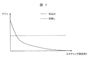
- FIG. 7 is a diagram showing the relationship between the gain and the steering steering angle ⁇ , and the vertical axis shows the gain and the horizontal axis shows the steering steering angle ⁇ .
- the gain at the time of turning of the steering wheel 3 is high at a position where the steering steering angle ⁇ is small, and changes so as to become a downward-sloping curve as the steering steering angle ⁇ becomes large.
- the gain is kept constant without changing due to the steering steering angle ⁇ .
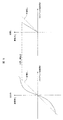
- FIG. 8 is a diagram showing the relationship between the steering steering angle ⁇ and the actual steering angle ⁇ f at the time of turning and turning back of the steering 3 according to the present embodiment.
- the steering angle ⁇ is shown on the horizontal axis and the actual steering angle ⁇ f is shown on the vertical axis, which are shown as gains of a function that changes the ratio of the actual steering angle ⁇ f (output) to the steering steering angle ⁇ (input). ing.
- the gain (first gain) of the continuous function that is convex upward with respect to the dotted line (without control) is set when the steering wheel 3 is turned.
- the upwardly convex gain is a continuously smooth curve. Further, the inclination of the continuous function that is convex upward increases as the absolute value of the steering steering angle ⁇ decreases, and the inclination approaches 0 as the absolute value of the steering steering angle ⁇ approaches the limit value. ..
- the actual steering angle ⁇ f of the wheel 11 with respect to the steering steering angle ⁇ is increased, and as the steering steering angle ⁇ increases, the actual steering angle ⁇ f of the wheel 11 with respect to the steering steering angle ⁇ f. Is gradually increased.
- the gain (first gain) is set so as to be convex upward with respect to the dotted line (without control), and the actual steering angle ⁇ f of the wheel 11 with respect to the steering steering angle ⁇ is changed. Therefore, it is possible to reduce the amount of cutting operation of the steering wheel 3 in reverse parking such as entering the garage, and it is possible to reduce the driving burden on the driver.
- the steering 3 is quickly turned back. Therefore, in the present embodiment, when the steering wheel 3 is turned back, the actual steering angle ⁇ f of the wheel 11 with respect to the steering steering angle ⁇ is increased, and the actual steering angle ⁇ f of the wheel 11 with respect to the steering steering angle ⁇ is quickly returned to the neutral position.
- the slope of the linear gain (second gain) may be changed based on the actual steering angle of the steering wheel.
- the arithmetic unit of the steering control device 2 calculates the ratio of the steering steering angle ⁇ to the actual steering angle of the steering wheel based on the actual steering angle of the steering wheel at the start of turning back of the steering wheel, and is linear.
- the amount of operation for turning back the steering wheel 3 in reverse parking such as entering the garage can be reduced, and the driving burden on the driver can be reduced.
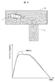
- FIG. 9 is a diagram showing the relationship between the steering steering angle ⁇ and time during reverse parking according to the present embodiment.
- Vehicle 1 is stopped on the roadway 70, and the driver is trying to park backward toward the parking space 71.
- the vehicle 1 moves like a locus P and moves to the parking space 71.
- the driver is required to perform a large steering operation.
- the relationship between the steering steering angle ⁇ and the time t becomes a curve as shown by the dotted line in the turning-back operation of the steering wheel 3.
- the steering steering angle ⁇ when the actual steering angle with respect to the steering steering angle ⁇ is controlled by using a gain that is convex upward at the cut of the steering 3 as shown in FIG. 8, the solid line shows. It becomes a curve like. That is, in the reverse parking, in the present embodiment, the steering steering angle ⁇ can be made smaller than in the case where the actual steering angle with respect to the steering steering angle ⁇ is not controlled, so that the amount of operation of the driver's steering 3 can be reduced. The driving burden on the driver can be reduced.
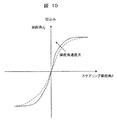
- FIG. 10 is a diagram showing the relationship between the steering steering angle ⁇ , the actual steering angle ⁇ f, and the steering angular velocity when the steering wheel 3 is turned according to the present embodiment.
- the actual steering angle ⁇ f with respect to the steering steering angle ⁇ is changed by using a gain that is convex upward, but the gain for changing the actual steering angle ⁇ f is changed according to the steering angular velocity. You may do so.
- the inclination of the continuous function that is convex upward increases as the absolute value of the steering angular velocity increases, and the inclination approaches 0 as the absolute value of the steering angle ⁇ approaches the limit value.
- a plurality of patterns are stored in the auxiliary storage device in advance, an appropriate gain is selected from the plurality of gains from the result calculated based on the steering steering angle ⁇ and the steering angular velocity, and the selected gain is selected.
- the program may be loaded into the main storage device and executed by the arithmetic unit.
- the gain can be switched according to the cutting speed of the driver's steering 3, and the driver's driving burden. Can be reduced.
Landscapes
- Engineering & Computer Science (AREA)
- Chemical & Material Sciences (AREA)
- Combustion & Propulsion (AREA)
- Transportation (AREA)
- Mechanical Engineering (AREA)
- Physics & Mathematics (AREA)
- Mathematical Physics (AREA)
- Steering Control In Accordance With Driving Conditions (AREA)
- Power Steering Mechanism (AREA)
Abstract
本発明は低速運転時におけるドライバの運転負荷を軽減することのできる操舵制御装置及び操舵制御方法を提供することを目的とする。本発明はステアリング3の操作量に基づき転舵輪アクチュエータ7を駆動して車輪11の舵角を変更し、転舵輪アクチュエータ7の制御量を演算する演算装置を備える。演算装置は、ステアリング3の切込みにおいては、ステアリング操舵角δに対する車輪11の実舵角の比率が変化する第1ゲインにより転舵輪アクチュエータ7を制御する。また、ステアリング3の切戻しにおいては第1ゲインと異なる第2ゲインにより転舵輪アクチュエータ7を制御する。
Description
本発明は、操舵制御装置及び操舵制御方法に関する。
運転者のステアリング操作を電動モータのアシスト力により操舵輪に伝達するようにした操舵制御装置においては、運転者のステアリング操作に対し、車両の状況に応じて操舵輪の操舵角を制御するようにした技術がある。操舵角を制御するために操舵制御装置には、ステアリングのギヤ比を変更する可変操舵機構が備えられている。このような技術として、例えば特許文献1及び特許文献2がある。
特許文献1に記載の技術においては、ステアリングの切り回し方向に応じて、切増し時のギヤ比Ga1、あるいは切戻し時のギヤ比Ga2を選択するようにしている。切増し時においては、速度-ギヤ比マップによって車速Vに対応したギヤ比Gb1を決定し、操舵角速度-ギヤ比ゲインマップによって車速Vに対応したギヤ比利得Gb2を決定し、ギヤ比Gb1にギヤ比利得Gb2を乗算して切増し時におけるギヤ比Ga1を算出するようにしている。そして、速度Vが低い場合においては、ギヤ比Gb1が高く設定され、ステアリング操作による操舵角が小さくても操舵輪による実舵角が大きく切れるようにし、急操舵の場合には、ギヤ比利得Gb2が1より低くしてステアリング操作に対する追従遅れを防止するようにしている。また、切戻し時においては、切増し時におけるギヤ比Ga1と異なるギヤ比Ga2を選択し、ステアリングを中立位置に位置させるようにしている。
次に、特許文献2に記載の技術においては、操舵トルク及びアシストトルクが小さい領域において、出力が小さくなるようにゲインを調整し、ハンドル戻し制御による滑らかな戻りの操舵感を実現するようにした技術が開示されている。
特許文献1に記載の技術においては、図6(A)(b)に示すように、ギヤ比Ga1とギヤ比Ga2は、所定の速度まで所定の傾きで直線的に変更され、所定の速度に達すると直線的な傾きが、別の傾きに変更されるように制御されている。したがって、ギヤ比の傾きが変更される速度においてギヤ比の急激な変化が起こり、ステアリング操作に違和感が残るといった課題があった。
特許文献2に記載の技術においては、操舵トルク及びアシストトルクのゲインを変更しているが、ステアリング操作に対する操舵角は変更されていないので、低速で運転を行う車庫入れ等後退駐車時においてはステアリングを大きく切り込まなければならず、ドライバの運転負荷がかかるといった課題があった。
本発明の目的は、低速運転時におけるドライバの運転負荷を軽減することのできる操舵制御装置及び操舵制御方法を提供することにある。
上記目的を達成するために本発明は、ステアリングの操作量に基づいて転舵輪アクチュエータを駆動して転舵輪の舵角を変更し、前記転舵輪アクチュエータの制御量を演算する演算装置を備えた操舵制御装置であって、前記演算装置は、前記ステアリングの切込みにおいては、ステアリング操舵角に対する前記転舵輪の実舵角の比率が変化する第1ゲインにより前記転舵輪アクチュエータを制御し、前記ステアリングの切戻しにおいては前記第1ゲインと異なる第2ゲインにより前記転舵輪アクチュエータを制御することを特徴とするものである。
また、本発明は、ステアリングの操作量に基づき、転舵輪アクチュエータを制御して転舵輪を操舵する操舵制御方法であって、前記ステアリングの切込みにおいては、ステアリング操舵角に対する前記転舵輪の実舵角の比率が変化する第1ゲインにより前記転舵輪が操舵され、前記ステアリングの切戻しにおいては前記第1ゲインと異なる第2ゲインにより前記転舵輪が操舵されることを特徴とするものである。
本発明によれば、低速運転時におけるドライバの運転負荷を軽減することのできる操舵制御装置及び操舵制御方法を提供することができる。
以下、本発明の実施例について添付の図面を参照しつつ説明する。同様の構成要素には同様の符号を付し、同様の説明は繰り返さない。
本発明の各種の構成要素は必ずしも個々に独立した存在である必要はなく、一の構成要素が複数の部材から成ること、複数の構成要素が一の部材から成ること、或る構成要素が別の構成要素の一部であること、或る構成要素の一部と他の構成要素の一部とが重複すること、などを許容する。
本実施例では、ステアリングとタイヤの間に機械的な結合を持たないステアバイワイヤシステムを例として説明する。ステアバイワイヤシステムは、ステアリングによる操舵量とタイヤの切れ角の変更を独立に制御できるものである。
図1は、本実施例に操舵制御装置2を搭載した車両1の概略構成図である。図1において、車両1にはドライバが操作するステアリング3と、ステアリング3の操舵角を検出する操舵角センサ4と、ステアリング3に入力した操舵トルクを検出する操舵トルクセンサ5と、車輪11の実舵角を制御する実舵角制御ユニット6と、実舵角制御ユニット6によって制御され車輪11(右前輪11FR、左前輪11FL)の舵角を変更する転舵輪アクチュエータ7と、段差等による反力を疑似的に発生させてステアリング3に疑似反力を伝達する疑似操舵反力発生装置8と、車両1の加速度を検出する加速度センサ9と、車両1の傾きを検出するジャイロセンサ10と、を備えている。加速度センサ9とジャイロセンサ10の検出信号は、操舵制御装置2に送信される。
車両1には4本の車輪11(右前輪11FR、左前輪11FL、右後輪11RR,左後輪11RL)が備えられている。右前輪11FR及び左前輪11FLは、転舵輪アクチュエータ7によって車両1の進行方向を変更するよう駆動される転舵輪となる。また、4本の車輪のそれぞれには車輪速センサ12(右前車輪速センサ12FR、左前車輪速センサ12FL、右後車輪速センサ12RR,左後車輪速センサ12RL)が備えられている。
車輪11(右前輪11FR、左前輪11FL:転舵輪)と転舵輪アクチュエータ7とを繋ぐ伝達部には、転舵輪アクチュエータ7の動作状況から車輪11の実舵角を検出する実舵角センサ13が備えられている。
転舵輪アクチュエータ7は、ステアリング3の操作量に基づいて転舵輪を駆動し、転舵輪の舵角を変更させる。転舵輪を駆動する転舵輪アクチュエータ7の制御量は、後述する演算装置で演算される。
操舵角センサ4、操舵トルクセンサ5、実舵角センサ13、右前車輪速センサ12FR、左前車輪速センサ12FL、右後車輪速センサ12RR,左後車輪速センサ12RLの検出信号は、通信バスライン14を介して操舵制御装置2に送信される。
次に、操舵制御装置2の構成について説明する。図2は、本実施例に係る操舵制御装置2のブロック図である。操舵制御装置2は、走行条件判定部20と、切込み/切戻し判定部21と、ゲイン調整部22が備えられている。操舵制御装置2には、操舵角センサ4で検出されたステアリング操舵角に関する信号と、車輪速センサ12,加速度センサ9で検出された車速に関する信号と、実舵角センサ13で検出された車輪11の実舵角と、シフトレバーの位置から前進あるいは後進といった車両の移動方向に関する信号が入力される。図示はしないが、操舵制御装置2は、CPU(Central Processing Unit)等の演算装置、主記憶装置、補助記憶装置、及び通信装置などのハードウェアを備えたECU(Electronic Control Unit)の一機能である。そして、補助記憶装置に記憶されたデータベースを参照しながら、主記憶装置にロードされたプログラムを演算装置が実行することで、走行条件判定部20、切込み/切戻し判定部21、ゲイン調整部22の各機能を実現する。
次に、操舵制御装置2の演算装置での処理について説明する。図3は本実施例に係る操舵制御装置の処理を示すフローチャート、図4は図3におけるステップS30の処理を示すフローチャート、図5は図3におけるステップS31の処理を示すフローチャートである。
ステップS30において、操舵制御装置2の走行条件判定部20は、車両1が特定の走行条件内に有るか否かを判断する。特定走行条件とは、例えば、車庫入れ等の後退駐車を意味している。走行条件判定部20におけるステップS30の処理について、図4を用いて説明する。図4において、自車が起動状態等の自車情報を取得する(ステップS40)。次に、車輪速センサ12、加速度センサ9で検出された信号から、車両1が極低速で走行しているか否かを判断する(ステップS41)。極低速とは、例えば車庫入れを行うような5km/h未満の速度である。本実施例では、車両1の速度(車速)を検出するにあたり、車輪速センサ12に加え、加速度センサ9を用いている。車輪11がスリップしている場合、車速を誤検知する場合があるので、本実施例では車輪速センサ12に加え、加速度センサ9を用いている。
ステップS41において、車速が極低速で走行している場合、シフトレバーが1回でもR位置(後退位置)に入ったか否かを判断する(ステップS42)。縦列駐車や後退駐車などの駐車パターンでは、車両1は前進と後退を繰り返すことが多く、少なくとも1回はシフトレバーがR(Reverse:後退)の位置に入る。シフトレバーが1回でもR位置(後退位置)に入れば、ステップS31へ進む。
ステップS41において、車両1が停止中、あるいは低速以上(例えば5km/h以上)である場合(Noの場合)には、Startに戻り、処理を繰り返す。ステップS42において、シフトレバーが一度でもR位置に入っていない場合(Noの場合)には、Startに戻り、処理を繰り返す。ステップS41及びステップS42のNoは、ステップS30のNoに該当する。
本実施例の演算装置は、車速が所定の速度未満であり、シフトレバーが後退に入ったことを条件として、後述する第1ゲイン及び第2ゲインによる転舵輪アクチュエータ7の制御を行うようにしている。
図3に戻り、ステップS31において、操舵制御装置2の切込み/切戻し判定部21は、ステアリング3が切込みであるか否かを判定する。切込み/切戻し判定部21におけるステップS31の処理を図5にて説明する。
図5において、操舵角センサ4にてステアリング3の操舵角速度を算出する。ステップS51において、ステアリング操舵角δとステアリング操舵角速度δ’の正負が一致しているか否かを判断する。
ここで、ステアリング操舵角δとステアリング操舵角速度δ’の正負について、図6を用いて説明する。図6は、本実施例に係るステアリング操舵角δとステアリング操舵角速度δ’の関係を示す図である。図中、縦軸と横軸の交点はステアリング3が中立の位置(中立点)にあり、ステアリング3の回転が停止(速度が0)している状態を示している。
ステアリング3は左右に切込みすることから、中立点を境にステアリング操舵角δ及びステアリング操舵角速度δ’が正負に変化する。例えば、ステアリング3が右側に切り込まれた場合のステアリング操舵角δを正(右側の領域)とすると、ステアリング3が左側に切り込まれた場合のステアリング操舵角δは負(左側の領域)となる。
ステアリング3は左右に切込みすることから、中立点を境にステアリング操舵角δ及びステアリング操舵角速度δ’が正負に変化する。例えば、ステアリング3が右側に切り込まれた場合のステアリング操舵角δを正(右側の領域)とすると、ステアリング3が左側に切り込まれた場合のステアリング操舵角δは負(左側の領域)となる。
また、ステアリング3が右側に切り込まれた場合のステアリング操舵角速度δ’を正(上側の領域)とすると、ステアリング3が左側に切り込まれた場合、及び右側に切り込まれたステアリング3を切戻す場合のステアリング操舵角速度δ’は負(下側の領域)となる。加えて、左側に切り込まれたステアリング3を切戻す場合のステアリング操舵角速度δ’は正(上側の領域)となる。
以上を纏めると、図6のような四象限の図となる。第一象限(右上)及び第三象限(左下)はステアリング3の切込み状態となり、第二象限(左上)及び第四象限(右下)はステアリング3の切戻し状態となる。すなわち、ステアリング操舵角δとステアリング操舵角速度δ’の正負が一致している場合(第一象限及び第三象限:正正もしくは負負)は、ステアリング3が切込み状態となり、ステアリング操舵角δとステアリング操舵角速度δ’の正負が一致していない場合(第二象限及び第四象限:正負もしくは負正)は、ステアリング3が切戻し状態となる。
図5に戻り、ステップS51において、ステアリング操舵角δとステアリング操舵角速度δ’の正負が一致している場合(Yes)は、ステアリング3が切込みと判定(ステップS52)し、ステップS32へと進む。ステップS51において、ステアリング操舵角δとステアリング操舵角速度δ’の正負が一致していない場合(No)は、ステアリング3が切戻しと判定(ステップS53)し、ステップS33へ進む。
図3に戻り、ステアリング3の切込み時と切戻し時の処理について説明する。本実施例では、ステアリング3の切込みにおいては、ステアリング操舵角に対する転舵輪(右前輪11FR、左前輪11FL)の実舵角の比率が変化するゲイン(第1ゲイン)により転舵輪アクチュエータ7を制御し、ステアリング3の切戻しにおいては第1ゲインと異なるゲイン(第2ゲイン)により転舵輪アクチュエータ7を制御することを特徴としている。
ステップS31において、ステアリング3が切込みである場合には、ステアリングの操舵角に対する転舵輪の実舵角の比率が上に凸な連続関数のゲイン(第1ゲイン)を選択する(ステップS32)。上に凸な連続関数は、ステアリング操舵角δとステアリング操舵角速度δ’に基づいて演算される。
一方、ステアリング3が切込みでない場合(切戻しの場合)には、ステアリングの操舵角に対する実舵角の比率が比例する関数となるような線形のゲイン(第2ゲイン)を選択する(ステップS33)。
そして、ステップS34において、それぞれのゲインに合わせた制御量が計算され、計算結果が操舵制御装置2から実舵角制御ユニット6に送信され、実舵角制御ユニット6よって転舵輪アクチュエータ7が制御される。そして、転舵輪アクチュエータ7により車輪11が操舵される。
次にステアリング操舵角δとゲインの関係について、図7を用いて説明する。図7は、ゲインとステアリング操舵角δとの関係を示す図であり、縦軸にゲイン、横軸にステアリング操舵角δを示している。図7において、ステアリング3の切込み時のゲインは、ステアリング操舵角δが小さい位置で高く、ステアリング操舵角δが大きくなるに従い、右下がりの曲線になるように変化している。一方、ステアリング3の切戻し時は、ステアリング操舵角δよって変化せず、ゲインが一定になるようにしている。
次に、図7のゲインを用いた場合におけるステアリング操舵角δと実舵角δfとの関係について説明する。
図8は、本実施例に係るステアリング3の切込み時と切戻し時におけるステアリング操舵角δと実舵角δfの関係を示す図である。図8では、横軸にステアリング操舵角δ、縦軸に実舵角δfを示しており、ステアリング操舵角δ(入力)に対する実舵角δf(出力)の比率が変化する関数のゲインとして示されている。
ステアリング3の切込み時と切戻し時において、ゲインを変更する制御を行わない場合、ステアリング操舵角δに対する実舵角δfのゲインは、点線(制御無し)のようになる。
本実施例では、ステアリング3の切込み時において、点線(制御無し)に対して上に凸な連続関数のゲイン(第1ゲイン)としている。上に凸となるゲインは、連続的に滑らかな曲線としている。また、上に凸な連続関数の傾きは、ステアリング操舵角δの絶対値が小さいほど大きくなっており、ステアリング操舵角δの絶対値が限界値に近づくほど傾きが0に近づくようになっている。
例えば、車庫入れ等の後退駐車を行う場合、ステアリング3の切込み量は大きくなる。
そこで、本実施例ではステアリング3の切始めは、ステアリング操舵角δに対する車輪11の実舵角δfを大きくし、ステアリング操舵角δが大きくなるに従い、ステアリング操舵角δに対する車輪11の実舵角δfを緩やかに増加させてゆく。
そこで、本実施例ではステアリング3の切始めは、ステアリング操舵角δに対する車輪11の実舵角δfを大きくし、ステアリング操舵角δが大きくなるに従い、ステアリング操舵角δに対する車輪11の実舵角δfを緩やかに増加させてゆく。
本実施例では、ステアリング3の切込み時において、点線(制御無し)に対して上に凸となるようなゲイン(第1ゲイン)とし、ステアリング操舵角δに対する車輪11の実舵角δfを変更するようにしているので、車庫入れ等の後退駐車でのステアリング3の切込み操作量を減少でき、ドライバの運転負担を軽減することができる。
また、本実施例では、ステアリング3の切戻し時において、ステアリング操舵角δが最大値付近でない場合(据え切りに近い状態ではない)、点線(制御無し)に対して傾きが大きくなるような線形のゲイン(第2ゲイン)としている。
例えば、車庫入れ等の後退駐車を行う場合、車両1の向きが駐車スペースの後退方向と一致した場合には、ステアリング3は素早く切戻した方が好ましい。そこで、本実施例ではステアリング3の切戻しは、ステアリング操舵角δに対する車輪11の実舵角δfを大きくし、ステアリング操舵角δに対する車輪11の実舵角δfを素早く中立位置に戻す。
線形のゲイン(第2ゲイン)の傾きは、転舵輪の実舵角に基づいて変更するようにしてもよい。その際、操舵制御装置2の演算装置では、ステアリングの切戻し開始時における転舵輪の実舵角に基づいて、ステアリング操舵角δと転舵輪の実舵角の比率を演算するようにして、線形のゲイン(第2ゲイン)を算出する。
本実施例では、車庫入れ等の後退駐車でのステアリング3の切戻し操作量を減少でき、ドライバの運転負担を軽減することができる。
次に、車両1の後退駐車時におけるステアリング操舵角δと時間の関係を説明する。図9は、本実施例に係る後退駐車時におけるステアリング操舵角δと時間の関係を示す図である。
車両1は車道70上に停止しており、ドライバは駐車スペース71に向かって後退駐車を行おうとしている。車両1は軌跡Pのように動き、駐車スペース71に移動する。後退駐車にあたり、ドライバは大きなステアリング操作が要求される。ステアリング操舵角δに対する実舵角に制御を行わない場合、ステアリング3の切込みから切戻し操作において、ステアリング操舵角δと時間tとの関係は、点線に示すような曲線となる。
これに対し、本実施例では、図8のようにステアリング3の切込みにおいて、上に凸となるようなゲインを用いて、ステアリング操舵角δに対する実舵角に制御を加えた場合、実線に示すような曲線となる。すなわち、後退駐車において本実施例では、ステアリング操舵角δに対する実舵角に制御を行わない場合に比べ、ステアリング操舵角δを小さくできるので、ドライバのステアリング3の操作量を減少することができ、ドライバの運転負担を軽減することができる。
図10は、本実施例に係るステアリング3の切込み時におけるステアリング操舵角δ、実舵角δf、操舵角速度の関係を示す図である。
本実施例では、上に凸となるようなゲインを用いてステアリング操舵角δに対する実舵角δfを変更するようにしたが、実舵角δfを変更するゲインは、操舵角速度に応じて変更するようにしても良い。
上に凸な連続関数の傾きは、操舵角速度の絶対値が大きいほど大きくなっており、ステアリング操舵角δの絶対値が限界値に近づくほど傾きが0に近づくようになっている。
上に凸な連続関数の傾きが大きくなると、操舵角速度が大きくなり、ステアリング操舵角δに対する実舵角δfを大きくすることができる。
ゲインは、予め複数のパターンを補助記憶装置に記憶するようにし、ステアリング操舵角δと操舵角速度に基づいて演算した結果から、複数のゲインの中から適切なゲインを選択し、選択されたゲインのプログラムを主記憶装置にロードして演算装置が実行するようにしてもよい。
本実施例によれば、ステアリング操舵角δと操舵角速度に応じて適切なゲインを選択するようにしているので、ドライバのステアリング3の切込み速度に応じてゲインを切り替えることができ、ドライバの運転負担を軽減することができる。
なお、本発明は、上述した実施例に限定するものではなく、様々な変形例が含まれる。
上述した実施例は本発明を分かり易く説明するために詳細に説明したものであり、必ずしも説明した全ての構成を備えるものに限定するものではない。
上述した実施例は本発明を分かり易く説明するために詳細に説明したものであり、必ずしも説明した全ての構成を備えるものに限定するものではない。
1…車両、2…操舵制御装置、3…ステアリング、4…操舵角センサ、5…操舵トルクセンサ、6…実舵角制御ユニット、7…転舵輪アクチュエータ、8…疑似操舵反力発生装置、9…加速度センサ、10…ジャイロセンサ、11…車輪、11FL…左前輪、11FR…右前輪、11RL…左後輪、11RR…右後輪、12…車輪速センサ、12FL…左前車輪速センサ、12FR…右前車輪速センサ、12RL…左後車輪速センサ、12RR…右後車輪速センサ、13…実舵角センサ、14…通信バスライン、20…走行条件判定部、21…切戻し判定部、22…ゲイン調整部、70…車道、71…駐車スペース
Claims (14)
- ステアリングの操作量に基づいて転舵輪アクチュエータを駆動して転舵輪の舵角を変更し、前記転舵輪アクチュエータの制御量を演算する演算装置を備えた操舵制御装置であって、
前記演算装置は、
前記ステアリングの切込みにおいては、ステアリング操舵角に対する前記転舵輪の実舵角の比率が変化する第1ゲインにより前記転舵輪アクチュエータを制御し、
前記ステアリングの切戻しにおいては前記第1ゲインと異なる第2ゲインにより前記転舵輪アクチュエータを制御することを特徴とする操舵制御装置。 - 請求項1において、
前記第1ゲインは、連続的な値であることを特徴とする操舵制御装置。 - 請求項1において、
前記第1ゲインはステアリング操舵角に対する前記転舵輪の実舵角の比率が上に凸な連続関数としたことを特徴とする操舵制御装置。 - 請求項3において、
前記上に凸な連続関数は、ステアリング操舵角と操舵角速度に基づいて演算することを特徴とする操舵制御装置。 - 請求項3において、
前記上に凸な連続関数の傾きは、ステアリング操舵角の絶対値が小さいほど大きくなることを特徴とする操舵制御装置。 - 請求項3において、
前記上に凸な連続関数の傾きは、操舵角速度の絶対値が大きいほど大きくなることを特徴とする操舵制御装置。 - 請求項3において、
前記上に凸な連続関数は、ステアリング操舵角の絶対値が限界値に近づくほど傾きが0に近づくことを特徴とする操舵制御装置。 - 請求項1乃至7の何れか1項において、
前記第2ゲインは、線形であることを特徴とする操舵制御装置。 - 請求項8において、
前記演算装置は、
前記ステアリングの切戻し開始時における前記転舵輪の実舵角に基づいて、ステアリング操舵角と前記転舵輪の実舵角の比率を演算することを特徴とする操舵制御装置。 - 請求項1において、
前記演算装置は、
車速が所定の速度未満であり、シフトレバーが後退に入ったことを条件として、前記第1ゲイン及び前記第2ゲインにより前記転舵輪アクチュエータを制御することを特徴とする操舵制御装置。 - ステアリングの操作量に基づき、転舵輪アクチュエータを制御して転舵輪を操舵する操舵制御方法であって、
前記ステアリングの切込みにおいては、ステアリング操舵角に対する前記転舵輪の実舵角の比率が変化する第1ゲインにより前記転舵輪が操舵され、
前記ステアリングの切戻しにおいては前記第1ゲインと異なる第2ゲインにより前記転舵輪が操舵されることを特徴とする操舵制御方法。 - 請求項11において、
前記第1ゲインは、連続的な値であることを特徴とする操舵制御方法。 - 請求項11において、
前記第1ゲインはステアリング操舵角に対する前記転舵輪の実舵角の比率が上に凸な連続関数としたことを特徴とする操舵制御方法。 - 請求項11乃至13の何れか1項において、
前記第2ゲインは、線形であることを特徴とする操舵制御方法。
Priority Applications (3)
| Application Number | Priority Date | Filing Date | Title |
|---|---|---|---|
| US17/761,340 US12221173B2 (en) | 2019-10-01 | 2020-09-10 | Steering control device and steering control method |
| CN202080061525.XA CN114340977B (zh) | 2019-10-01 | 2020-09-10 | 操舵控制装置及操舵控制方法 |
| DE112020003994.3T DE112020003994B4 (de) | 2019-10-01 | 2020-09-10 | Lenksteuerungsvorrichtung und lenksteuerungsverfahren |
Applications Claiming Priority (2)
| Application Number | Priority Date | Filing Date | Title |
|---|---|---|---|
| JP2019181089A JP7389605B2 (ja) | 2019-10-01 | 2019-10-01 | 操舵制御装置 |
| JP2019-181089 | 2019-10-01 |
Publications (1)
| Publication Number | Publication Date |
|---|---|
| WO2021065408A1 true WO2021065408A1 (ja) | 2021-04-08 |
Family
ID=75272137
Family Applications (1)
| Application Number | Title | Priority Date | Filing Date |
|---|---|---|---|
| PCT/JP2020/034275 Ceased WO2021065408A1 (ja) | 2019-10-01 | 2020-09-10 | 操舵制御装置及び操舵制御方法 |
Country Status (5)
| Country | Link |
|---|---|
| US (1) | US12221173B2 (ja) |
| JP (1) | JP7389605B2 (ja) |
| CN (1) | CN114340977B (ja) |
| DE (1) | DE112020003994B4 (ja) |
| WO (1) | WO2021065408A1 (ja) |
Families Citing this family (3)
| Publication number | Priority date | Publication date | Assignee | Title |
|---|---|---|---|---|
| JP7388335B2 (ja) * | 2020-10-23 | 2023-11-29 | 株式会社デンソー | 操舵制御装置、操舵制御方法、操舵制御プログラム |
| JP7553418B2 (ja) * | 2021-09-30 | 2024-09-18 | 本田技研工業株式会社 | 車両 |
| EP4588756B1 (en) * | 2024-01-16 | 2026-03-11 | Volvo Car Corporation | Method for providing a steering ratio for a steer-by-wire system, method for operating a steer-by-wire system, use, data processing apparatus, computer program, computer-readable storage medium, steer-by-wire system, and vehicle |
Citations (9)
| Publication number | Priority date | Publication date | Assignee | Title |
|---|---|---|---|---|
| JP2002046639A (ja) * | 2000-08-07 | 2002-02-12 | Koyo Seiko Co Ltd | 車両用操舵装置 |
| JP2003081109A (ja) * | 2001-09-10 | 2003-03-19 | Nissan Motor Co Ltd | 車両用舵角比制御装置 |
| JP2007090924A (ja) * | 2005-09-27 | 2007-04-12 | Toyota Motor Corp | 車両の操舵装置 |
| JP2007137400A (ja) * | 2005-10-20 | 2007-06-07 | Toyota Motor Corp | 車両の操舵装置 |
| JP2008062788A (ja) * | 2006-09-07 | 2008-03-21 | Toyota Motor Corp | 車両の操舵装置 |
| US20100025144A1 (en) * | 2008-07-31 | 2010-02-04 | Gm Global Technology Operations, Inc. | Control adaptation of variable gear ratio steering |
| JP2012228988A (ja) * | 2011-04-27 | 2012-11-22 | Jtekt Corp | 車両用操舵装置 |
| JP2012254705A (ja) * | 2011-06-08 | 2012-12-27 | Jtekt Corp | 車両用操舵装置及び荷役車両 |
| JP2016107871A (ja) * | 2014-12-08 | 2016-06-20 | 株式会社ジェイテクト | 車両用操舵装置 |
Family Cites Families (12)
| Publication number | Priority date | Publication date | Assignee | Title |
|---|---|---|---|---|
| JPH0128965Y2 (ja) | 1985-07-12 | 1989-09-04 | ||
| JP3646026B2 (ja) * | 1999-10-12 | 2005-05-11 | 光洋精工株式会社 | 車両用操舵装置 |
| JP2004042796A (ja) * | 2002-07-12 | 2004-02-12 | Toyoda Mach Works Ltd | 車両の運動制御方法および車両の運動制御装置 |
| JP2010095075A (ja) * | 2008-10-15 | 2010-04-30 | Jtekt Corp | 車両用操舵装置 |
| JP5298822B2 (ja) * | 2008-12-12 | 2013-09-25 | 日本精工株式会社 | 電動パワーステアリング装置 |
| EP2495156B1 (en) * | 2009-10-30 | 2015-10-21 | Toyota Jidosha Kabushiki Kaisha | Device for controlling vehicle travel |
| WO2011108688A1 (ja) * | 2010-03-04 | 2011-09-09 | 本田技研工業株式会社 | 車両の旋回制御装置 |
| CN104411558B (zh) * | 2012-07-06 | 2017-09-22 | 丰田自动车株式会社 | 车辆的行驶控制装置 |
| WO2015159762A1 (ja) * | 2014-04-16 | 2015-10-22 | 日本精工株式会社 | 電動パワーステアリング装置 |
| CN107428365B (zh) * | 2015-02-25 | 2018-10-23 | 日本精工株式会社 | 电动助力转向装置 |
| JP6270250B1 (ja) * | 2016-09-21 | 2018-01-31 | マツダ株式会社 | 車両用挙動制御装置 |
| US10618548B2 (en) | 2017-02-02 | 2020-04-14 | Nsk Ltd. | Electric power steering apparatus |
-
2019
- 2019-10-01 JP JP2019181089A patent/JP7389605B2/ja active Active
-
2020
- 2020-09-10 US US17/761,340 patent/US12221173B2/en active Active
- 2020-09-10 WO PCT/JP2020/034275 patent/WO2021065408A1/ja not_active Ceased
- 2020-09-10 DE DE112020003994.3T patent/DE112020003994B4/de active Active
- 2020-09-10 CN CN202080061525.XA patent/CN114340977B/zh active Active
Patent Citations (9)
| Publication number | Priority date | Publication date | Assignee | Title |
|---|---|---|---|---|
| JP2002046639A (ja) * | 2000-08-07 | 2002-02-12 | Koyo Seiko Co Ltd | 車両用操舵装置 |
| JP2003081109A (ja) * | 2001-09-10 | 2003-03-19 | Nissan Motor Co Ltd | 車両用舵角比制御装置 |
| JP2007090924A (ja) * | 2005-09-27 | 2007-04-12 | Toyota Motor Corp | 車両の操舵装置 |
| JP2007137400A (ja) * | 2005-10-20 | 2007-06-07 | Toyota Motor Corp | 車両の操舵装置 |
| JP2008062788A (ja) * | 2006-09-07 | 2008-03-21 | Toyota Motor Corp | 車両の操舵装置 |
| US20100025144A1 (en) * | 2008-07-31 | 2010-02-04 | Gm Global Technology Operations, Inc. | Control adaptation of variable gear ratio steering |
| JP2012228988A (ja) * | 2011-04-27 | 2012-11-22 | Jtekt Corp | 車両用操舵装置 |
| JP2012254705A (ja) * | 2011-06-08 | 2012-12-27 | Jtekt Corp | 車両用操舵装置及び荷役車両 |
| JP2016107871A (ja) * | 2014-12-08 | 2016-06-20 | 株式会社ジェイテクト | 車両用操舵装置 |
Also Published As
| Publication number | Publication date |
|---|---|
| DE112020003994T5 (de) | 2022-06-02 |
| DE112020003994B4 (de) | 2025-05-28 |
| CN114340977B (zh) | 2023-09-29 |
| CN114340977A (zh) | 2022-04-12 |
| US20220340195A1 (en) | 2022-10-27 |
| US12221173B2 (en) | 2025-02-11 |
| JP7389605B2 (ja) | 2023-11-30 |
| JP2021054337A (ja) | 2021-04-08 |
Similar Documents
| Publication | Publication Date | Title |
|---|---|---|
| CN115140157B (zh) | 用于车辆的转向控制方法、装置、存储介质及车辆 | |
| KR102274126B1 (ko) | 전동식 조향 시스템의 제어 장치 및 방법 | |
| JP2538939B2 (ja) | 車両の舵角制御装置 | |
| US20220126914A1 (en) | Method and System for Controlling In-Situ Rotation Mode of Four-Wheel Independent Steering Type Vehicle | |
| JP5338491B2 (ja) | 車両用操舵装置および車両用操舵方法 | |
| US20230038390A1 (en) | Steer-by-wire steering system with acceleration dependent steering torque feedback | |
| CN114340977B (zh) | 操舵控制装置及操舵控制方法 | |
| JP3896995B2 (ja) | 車両用走行支援装置 | |
| JP2004352110A (ja) | 車両用走行支援装置 | |
| KR102323885B1 (ko) | 차량의 조향 제어 방법 | |
| US7548807B2 (en) | Method for steering a vehicle with superimposed steering | |
| JP3934082B2 (ja) | 走行支援装置 | |
| JPH06263050A (ja) | パワーステアリング装置 | |
| US20250229831A1 (en) | Method to control a steer-by-wire steering system of a road vehicle with active inertia feedback | |
| US11312414B2 (en) | Motor driven power steering and control method thereof | |
| JP7861657B2 (ja) | 四輪操舵車両の制御装置 | |
| JP2006096187A (ja) | 車両用操舵装置 | |
| KR20110080758A (ko) | 능동 전륜 조향 시스템의 조향 제어방법 | |
| KR20200124366A (ko) | 차량용 조향 제어방법 및 시스템 | |
| JP2005059645A (ja) | ステア・バイ・ワイヤ式操舵装置におけるウインカーキャンセル装置 | |
| JP4576881B2 (ja) | 車両用自動操舵装置 | |
| KR101227163B1 (ko) | 조향 시스템 및 그 제어 방법 | |
| KR20210152284A (ko) | 차량용 후륜 조향 제어방법 | |
| JP3565264B2 (ja) | 車両用操舵制御装置 | |
| US20250108858A1 (en) | Rear wheel steering apparatus |
Legal Events
| Date | Code | Title | Description |
|---|---|---|---|
| 121 | Ep: the epo has been informed by wipo that ep was designated in this application |
Ref document number: 20873099 Country of ref document: EP Kind code of ref document: A1 |
|
| 122 | Ep: pct application non-entry in european phase |
Ref document number: 20873099 Country of ref document: EP Kind code of ref document: A1 |
|
| WWG | Wipo information: grant in national office |
Ref document number: 112020003994 Country of ref document: DE |