WO2021065355A1 - Refractory material - Google Patents
Refractory material Download PDFInfo
- Publication number
- WO2021065355A1 WO2021065355A1 PCT/JP2020/033680 JP2020033680W WO2021065355A1 WO 2021065355 A1 WO2021065355 A1 WO 2021065355A1 JP 2020033680 W JP2020033680 W JP 2020033680W WO 2021065355 A1 WO2021065355 A1 WO 2021065355A1
- Authority
- WO
- WIPO (PCT)
- Prior art keywords
- sic
- glass layer
- refractory
- mass
- base material
- Prior art date
Links
Images


Classifications
-
- C—CHEMISTRY; METALLURGY
- C04—CEMENTS; CONCRETE; ARTIFICIAL STONE; CERAMICS; REFRACTORIES
- C04B—LIME, MAGNESIA; SLAG; CEMENTS; COMPOSITIONS THEREOF, e.g. MORTARS, CONCRETE OR LIKE BUILDING MATERIALS; ARTIFICIAL STONE; CERAMICS; REFRACTORIES; TREATMENT OF NATURAL STONE
- C04B35/00—Shaped ceramic products characterised by their composition; Ceramics compositions; Processing powders of inorganic compounds preparatory to the manufacturing of ceramic products
- C04B35/66—Monolithic refractories or refractory mortars, including those whether or not containing clay
-
- C—CHEMISTRY; METALLURGY
- C04—CEMENTS; CONCRETE; ARTIFICIAL STONE; CERAMICS; REFRACTORIES
- C04B—LIME, MAGNESIA; SLAG; CEMENTS; COMPOSITIONS THEREOF, e.g. MORTARS, CONCRETE OR LIKE BUILDING MATERIALS; ARTIFICIAL STONE; CERAMICS; REFRACTORIES; TREATMENT OF NATURAL STONE
- C04B35/00—Shaped ceramic products characterised by their composition; Ceramics compositions; Processing powders of inorganic compounds preparatory to the manufacturing of ceramic products
- C04B35/515—Shaped ceramic products characterised by their composition; Ceramics compositions; Processing powders of inorganic compounds preparatory to the manufacturing of ceramic products based on non-oxide ceramics
- C04B35/56—Shaped ceramic products characterised by their composition; Ceramics compositions; Processing powders of inorganic compounds preparatory to the manufacturing of ceramic products based on non-oxide ceramics based on carbides or oxycarbides
- C04B35/565—Shaped ceramic products characterised by their composition; Ceramics compositions; Processing powders of inorganic compounds preparatory to the manufacturing of ceramic products based on non-oxide ceramics based on carbides or oxycarbides based on silicon carbide
-
- C—CHEMISTRY; METALLURGY
- C04—CEMENTS; CONCRETE; ARTIFICIAL STONE; CERAMICS; REFRACTORIES
- C04B—LIME, MAGNESIA; SLAG; CEMENTS; COMPOSITIONS THEREOF, e.g. MORTARS, CONCRETE OR LIKE BUILDING MATERIALS; ARTIFICIAL STONE; CERAMICS; REFRACTORIES; TREATMENT OF NATURAL STONE
- C04B41/00—After-treatment of mortars, concrete, artificial stone or ceramics; Treatment of natural stone
- C04B41/009—After-treatment of mortars, concrete, artificial stone or ceramics; Treatment of natural stone characterised by the material treated
-
- C—CHEMISTRY; METALLURGY
- C04—CEMENTS; CONCRETE; ARTIFICIAL STONE; CERAMICS; REFRACTORIES
- C04B—LIME, MAGNESIA; SLAG; CEMENTS; COMPOSITIONS THEREOF, e.g. MORTARS, CONCRETE OR LIKE BUILDING MATERIALS; ARTIFICIAL STONE; CERAMICS; REFRACTORIES; TREATMENT OF NATURAL STONE
- C04B41/00—After-treatment of mortars, concrete, artificial stone or ceramics; Treatment of natural stone
- C04B41/45—Coating or impregnating, e.g. injection in masonry, partial coating of green or fired ceramics, organic coating compositions for adhering together two concrete elements
- C04B41/50—Coating or impregnating, e.g. injection in masonry, partial coating of green or fired ceramics, organic coating compositions for adhering together two concrete elements with inorganic materials
- C04B41/5022—Coating or impregnating, e.g. injection in masonry, partial coating of green or fired ceramics, organic coating compositions for adhering together two concrete elements with inorganic materials with vitreous materials
-
- C—CHEMISTRY; METALLURGY
- C04—CEMENTS; CONCRETE; ARTIFICIAL STONE; CERAMICS; REFRACTORIES
- C04B—LIME, MAGNESIA; SLAG; CEMENTS; COMPOSITIONS THEREOF, e.g. MORTARS, CONCRETE OR LIKE BUILDING MATERIALS; ARTIFICIAL STONE; CERAMICS; REFRACTORIES; TREATMENT OF NATURAL STONE
- C04B41/00—After-treatment of mortars, concrete, artificial stone or ceramics; Treatment of natural stone
- C04B41/53—After-treatment of mortars, concrete, artificial stone or ceramics; Treatment of natural stone involving the removal of at least part of the materials of the treated article, e.g. etching, drying of hardened concrete
-
- C—CHEMISTRY; METALLURGY
- C04—CEMENTS; CONCRETE; ARTIFICIAL STONE; CERAMICS; REFRACTORIES
- C04B—LIME, MAGNESIA; SLAG; CEMENTS; COMPOSITIONS THEREOF, e.g. MORTARS, CONCRETE OR LIKE BUILDING MATERIALS; ARTIFICIAL STONE; CERAMICS; REFRACTORIES; TREATMENT OF NATURAL STONE
- C04B41/00—After-treatment of mortars, concrete, artificial stone or ceramics; Treatment of natural stone
- C04B41/80—After-treatment of mortars, concrete, artificial stone or ceramics; Treatment of natural stone of only ceramics
- C04B41/81—Coating or impregnation
- C04B41/85—Coating or impregnation with inorganic materials
- C04B41/86—Glazes; Cold glazes
-
- C—CHEMISTRY; METALLURGY
- C04—CEMENTS; CONCRETE; ARTIFICIAL STONE; CERAMICS; REFRACTORIES
- C04B—LIME, MAGNESIA; SLAG; CEMENTS; COMPOSITIONS THEREOF, e.g. MORTARS, CONCRETE OR LIKE BUILDING MATERIALS; ARTIFICIAL STONE; CERAMICS; REFRACTORIES; TREATMENT OF NATURAL STONE
- C04B41/00—After-treatment of mortars, concrete, artificial stone or ceramics; Treatment of natural stone
- C04B41/80—After-treatment of mortars, concrete, artificial stone or ceramics; Treatment of natural stone of only ceramics
- C04B41/81—Coating or impregnation
- C04B41/85—Coating or impregnation with inorganic materials
- C04B41/87—Ceramics
-
- C—CHEMISTRY; METALLURGY
- C04—CEMENTS; CONCRETE; ARTIFICIAL STONE; CERAMICS; REFRACTORIES
- C04B—LIME, MAGNESIA; SLAG; CEMENTS; COMPOSITIONS THEREOF, e.g. MORTARS, CONCRETE OR LIKE BUILDING MATERIALS; ARTIFICIAL STONE; CERAMICS; REFRACTORIES; TREATMENT OF NATURAL STONE
- C04B41/00—After-treatment of mortars, concrete, artificial stone or ceramics; Treatment of natural stone
- C04B41/80—After-treatment of mortars, concrete, artificial stone or ceramics; Treatment of natural stone of only ceramics
- C04B41/91—After-treatment of mortars, concrete, artificial stone or ceramics; Treatment of natural stone of only ceramics involving the removal of part of the materials of the treated articles, e.g. etching
-
- F—MECHANICAL ENGINEERING; LIGHTING; HEATING; WEAPONS; BLASTING
- F27—FURNACES; KILNS; OVENS; RETORTS
- F27D—DETAILS OR ACCESSORIES OF FURNACES, KILNS, OVENS, OR RETORTS, IN SO FAR AS THEY ARE OF KINDS OCCURRING IN MORE THAN ONE KIND OF FURNACE
- F27D1/00—Casings; Linings; Walls; Roofs
-
- C—CHEMISTRY; METALLURGY
- C04—CEMENTS; CONCRETE; ARTIFICIAL STONE; CERAMICS; REFRACTORIES
- C04B—LIME, MAGNESIA; SLAG; CEMENTS; COMPOSITIONS THEREOF, e.g. MORTARS, CONCRETE OR LIKE BUILDING MATERIALS; ARTIFICIAL STONE; CERAMICS; REFRACTORIES; TREATMENT OF NATURAL STONE
- C04B2235/00—Aspects relating to ceramic starting mixtures or sintered ceramic products
- C04B2235/02—Composition of constituents of the starting material or of secondary phases of the final product
- C04B2235/30—Constituents and secondary phases not being of a fibrous nature
- C04B2235/42—Non metallic elements added as constituents or additives, e.g. sulfur, phosphor, selenium or tellurium
- C04B2235/428—Silicon
-
- C—CHEMISTRY; METALLURGY
- C04—CEMENTS; CONCRETE; ARTIFICIAL STONE; CERAMICS; REFRACTORIES
- C04B—LIME, MAGNESIA; SLAG; CEMENTS; COMPOSITIONS THEREOF, e.g. MORTARS, CONCRETE OR LIKE BUILDING MATERIALS; ARTIFICIAL STONE; CERAMICS; REFRACTORIES; TREATMENT OF NATURAL STONE
- C04B2235/00—Aspects relating to ceramic starting mixtures or sintered ceramic products
- C04B2235/65—Aspects relating to heat treatments of ceramic bodies such as green ceramics or pre-sintered ceramics, e.g. burning, sintering or melting processes
- C04B2235/656—Aspects relating to heat treatments of ceramic bodies such as green ceramics or pre-sintered ceramics, e.g. burning, sintering or melting processes characterised by specific heating conditions during heat treatment
- C04B2235/6562—Heating rate
-
- C—CHEMISTRY; METALLURGY
- C04—CEMENTS; CONCRETE; ARTIFICIAL STONE; CERAMICS; REFRACTORIES
- C04B—LIME, MAGNESIA; SLAG; CEMENTS; COMPOSITIONS THEREOF, e.g. MORTARS, CONCRETE OR LIKE BUILDING MATERIALS; ARTIFICIAL STONE; CERAMICS; REFRACTORIES; TREATMENT OF NATURAL STONE
- C04B2235/00—Aspects relating to ceramic starting mixtures or sintered ceramic products
- C04B2235/65—Aspects relating to heat treatments of ceramic bodies such as green ceramics or pre-sintered ceramics, e.g. burning, sintering or melting processes
- C04B2235/656—Aspects relating to heat treatments of ceramic bodies such as green ceramics or pre-sintered ceramics, e.g. burning, sintering or melting processes characterised by specific heating conditions during heat treatment
- C04B2235/6567—Treatment time
-
- C—CHEMISTRY; METALLURGY
- C04—CEMENTS; CONCRETE; ARTIFICIAL STONE; CERAMICS; REFRACTORIES
- C04B—LIME, MAGNESIA; SLAG; CEMENTS; COMPOSITIONS THEREOF, e.g. MORTARS, CONCRETE OR LIKE BUILDING MATERIALS; ARTIFICIAL STONE; CERAMICS; REFRACTORIES; TREATMENT OF NATURAL STONE
- C04B2235/00—Aspects relating to ceramic starting mixtures or sintered ceramic products
- C04B2235/65—Aspects relating to heat treatments of ceramic bodies such as green ceramics or pre-sintered ceramics, e.g. burning, sintering or melting processes
- C04B2235/658—Atmosphere during thermal treatment
- C04B2235/6583—Oxygen containing atmosphere, e.g. with changing oxygen pressures
-
- C—CHEMISTRY; METALLURGY
- C04—CEMENTS; CONCRETE; ARTIFICIAL STONE; CERAMICS; REFRACTORIES
- C04B—LIME, MAGNESIA; SLAG; CEMENTS; COMPOSITIONS THEREOF, e.g. MORTARS, CONCRETE OR LIKE BUILDING MATERIALS; ARTIFICIAL STONE; CERAMICS; REFRACTORIES; TREATMENT OF NATURAL STONE
- C04B2235/00—Aspects relating to ceramic starting mixtures or sintered ceramic products
- C04B2235/70—Aspects relating to sintered or melt-casted ceramic products
- C04B2235/96—Properties of ceramic products, e.g. mechanical properties such as strength, toughness, wear resistance
Definitions
- Patent Document 1 Japanese Unexamined Patent Publication No. 2008-94652 discloses a refractory using a SiC-silicon substrate containing SiC particles as a main component and metallic Si between the SiC particles. .. Since the Si—SiC refractory has excellent thermal conductivity, a temperature difference is unlikely to occur in the refractory. Therefore, the Si—SiC refractory has an advantage that it can suppress damage due to thermal stress.
- the Si—SiC material base material is also excellent in heat resistance and fire resistance, and is promising as a material for producing a refractory material.
- a SiC-SiC refractory is produced by producing a SiC molded body, then bringing metallic Si into contact with the SiC molded body and heating it in an inert gas atmosphere under low pressure conditions.
- a Si component that is, a metallic Si or a Si compound that has not been impregnated in the SiC molding body remains. Therefore, in the case of a SiC-SiC refractory, a step of impregnating the inside of the SiC molding with metallic Si and then removing the Si component remaining on the surface is required.
- the surface of the SiC-SiC refractory may be scratched and cracks may occur starting from the scratch.
- the strength of the SiC-SiC refractory may decrease.
- the present specification provides a technique for suppressing a decrease in strength of a SiC-SiC refractory.
- the refractory material disclosed herein may include a SiC-SiC material base material and a glass layer.
- the SiC-SiC material base material is mainly composed of SiC particles, and metallic Si may be contained between the SiC particles.
- the glass layer may be mainly composed of SiO 2 that covers the surface of the SiC-silicon substrate.
- the mass ratio of the glass layer to the SiC-SiC material base material may be 0.001% by mass or more and 5% by mass or less.
- a flowchart for manufacturing a refractory is shown.
- An SEM photograph of the vicinity of the surface of the refractory is shown.
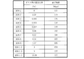
- the relationship between the mass ratio of the glass layer to the Si—SiC material substrate and the strength is shown.
- the refractory material disclosed in the present specification is used as a component constituting the firing furnace such as the inner wall of the firing furnace, or as a part used in the firing furnace such as a rack and a setter. Although not particularly limited, the refractory material disclosed in the present specification can be suitably used in an environment where the maximum temperature is 500 to 1350 ° C.
- the shape of the refractory may be flat plate, box, columnar, block, tubular or the like.
- the thickness of the refractory may be 0.1 to 20 mm.
- the refractory may include a SiC-silicon substrate and a glass layer that covers the surface of the SiC-SiC substrate.
- the conventional refractory made of a SiC material base material has a step of removing Si (or a Si compound) remaining on the surface after molding the SiC material fired body. Therefore, in the conventional refractory, even if a glass layer is formed on the surface in the process of producing the SiC-SiC refractory, the glass layer is also removed in the step of removing Si on the surface. That is, the refractory material made of the conventional SiC-SiC material base material does not have a glass layer on the surface.
- the surface of the SiC-silicon substrate By coating the surface of the SiC-silicon substrate with a glass layer, it is possible to prevent the refractory from being damaged starting from the recesses (scratches, etc.) on the surface of the SiC substrate.
- the surface of the SiC material base material by coating the surface of the SiC material base material with a glass layer, when stress is applied to the base material surface due to thermal expansion and contraction of the SiC material base material, the base material surface It is possible to suppress the concentration of stress in the recesses of the silicon and suppress the damage of the refractory.
- the SiC-SiC material base material is mainly composed of SiC particles, and metallic Si may be contained between the SiC particles.
- mainly SiC particles means that the ratio (mass%) of SiC particles to the SiC-SiC material base material is larger than 50% by mass.
- the ratio of SiC particles to the SiC-SiC material base material may be 55% by mass or more, 60% by mass or more, 70% by mass or more, and 80% by mass or more. May be.
- the size (average particle size) of the SiC particles may be 5 ⁇ m or more and 100 ⁇ m or less.
- the size (average particle size) of the SiC particles may be 10 ⁇ m or more, 20 ⁇ m or more, and 30 ⁇ m or more.
- the size of the SiC particles may be 80 ⁇ m or less, 70 ⁇ m or less, and 60 ⁇ m or less.
- the ratio (mass%) of metallic Si to the Si—SiC material base material may be 5 to 40% by mass. If the ratio of metallic Si to the SiC-silicon substrate is too small, the amount of voids between the SiC particles becomes large (the porosity of the SiC-silicon substrate is high), and the strength of the SiC-silicon substrate decreases. I have something to do. On the other hand, if the proportion of metallic Si in the SiC-silicon substrate is too large, cracks are likely to occur during use (when the refractory is exposed to high temperatures), and the strength of the SiC-silicon substrate becomes high. May decrease.
- the ratio of metallic Si to the SiC material base material is determined by the ratio of SiC particles to the SiC material base material.
- metallic Si is impregnated between the SiC particles so that the apparent porosity of the SiC-silicon substrate is 5% or less.
- the apparent porosity of the SiC-silicon substrate is more preferably 2% or less, and particularly preferably 1% or less.
- Concavities and convexities may be formed on the surface of the Si—SiC material base material.
- the surface roughness Rz (ISO 1997, JIS B 0601: 2001) of the unevenness on the surface of the SiC-silicon substrate may be 1 ⁇ m or more and 150 ⁇ m or less. By setting the surface roughness Rz of the unevenness to 1 ⁇ m or more, the adhesion between the SiC material base material and the glass layer is improved.
- the surface roughness Rz of the unevenness may be larger than the thickness (average thickness) of the glass layer, for example, 5 ⁇ m or more, 10 ⁇ m or more, 30 ⁇ m or more, 50 ⁇ m or more. You can.
- the surface roughness Rz of the unevenness may be 120 ⁇ m or less, 100 ⁇ m or less, 80 ⁇ m or less, and 60 ⁇ m or less.
- the SiC-SiC refractory has a step of impregnating the inside of the SiC molding with metallic Si and then removing the Si remaining on the surface.
- the irregularities on the surface of the Si—SiC material base material may be formed in the step of removing the Si component from the surface of the Si—SiC material base material, or may be performed separately from the step of removing the Si component.
- the surface of the Si—SiC material base material may be scratched in the step of removing the Si component, and cracks may occur starting from the scratches.
- the technique disclosed in the present specification can also be regarded as a technique for suppressing the occurrence of cracks in the fired product without removing the scratches generated in the step of removing the Si component.
- the glass layer may cover the entire surface of the SiC-silicon substrate.
- the thickness of the glass layer may be 0.1 ⁇ m or more and 150 ⁇ m or less.
- the effect of suppressing the occurrence of cracks can be sufficiently obtained.
- a force (stress) is applied from the glass layer to the SiC material base material to crack based on the difference in the coefficient of thermal expansion between the SiC material base material and the glass layer. Can be suppressed.
- the thickness (average thickness) of the glass layer is preferably thinner than the surface roughness Rz of the unevenness of the surface of the SiC material substrate, for example, it may be 100 ⁇ m or less, 60 ⁇ m or less, and 40 ⁇ m or less. May be.
- the thickness of the glass layer may be 0.5 ⁇ m or more, 1 ⁇ m or more, 5 ⁇ m or more, and 10 ⁇ m or more.
- the mass ratio of the glass layer to the Si—SiC material base material may be 0.001% by mass or more and 5% by mass or less. Within this range, the strength of the refractory can be improved and the occurrence of cracks can be suppressed. When the mass ratio is less than 0.001% by mass, it becomes difficult to obtain the effect of suppressing the occurrence of cracks. When the mass ratio exceeds 5% by mass, the ratio of the glass layer to the SiC-silicon substrate is too high, and it becomes difficult to obtain a high-strength refractory.
- the mass ratio of the glass layer to the Si—SiC material base material may be 0.003% by mass or more, 0.02% by mass or more, or 0.08% by mass or more. Further, the mass ratio of the glass layer to the SiC-SiC material base material may be 3% by mass or less, and may be 1% by mass or less.
- the mass ratio of the glass layer to the Si—SiC material base material can be calculated from the mass of the base material before the formation of the glass layer and the mass of the entire refractory after the formation of the glass layer, and the mass of both.
- the mass ratio of the glass layer to the SiC-silicon substrate is calculated by calculating the volume of the SiC-SiC substrate and the glass layer in the refractory from image analysis such as SEM and CT, and the SiC-SiC substrate and the glass.
- the masses of the SiC-silicon substrate and the glass layer can be calculated from the density of the layers, and can be calculated from the obtained masses of both.
- the glass layer may be mainly composed of SiO 2 , and may contain one or more of the elements Al, Ca, Fe, Na, K, Mg, Sr and Ba. That is, the glass layer may be a SiO 2 alone, it referred to as SiO 2 of more than 50 mass%, Al, Ca, Fe, Na, K, Mg, Sr, Ba elements (hereinafter, the auxiliary element ) Or a compound of the subcomponent element (for example, an oxide of the subcomponent element).
- the auxiliary element a compound of the subcomponent element
- the temperature at which the glass layer is formed can be lowered and the formation time can be shortened. That is, the glass layer containing the sub-component element can simplify the forming process as compared with the glass layer containing no sub-component element.
- the glass layer preferably contains one or more of the above-mentioned subcomponent elements, Al, Ca, Fe, Na and K elements (hereinafter, referred to as first subcomponent elements).
- the first subcomponent element (compound of the first subcomponent element) is relatively easily available and is chemically stable and therefore easy to handle.
- the subcomponent element may be present as a compound in the glass layer, and is particularly preferably present as an oxide.
- the glass layer can be formed by forming irregularities on the surface of the SiC-silicon substrate and then heating (firing) the SiC-SiC substrate in an oxidizing atmosphere.
- SiO 2 which is the main material of the glass layer, may be a partially oxidized version of Si constituting the SiC-silicon substrate, or the glass layer containing Si on the surface of the SiC-SiC substrate.
- the raw material for the glass layer may be arranged and the Si component contained in the raw material for the glass layer may be oxidized. When the glass layer contains the above-mentioned subcomponent elements, the raw material for the glass layer may contain the subcomponent elements.
- the raw material for the glass layer may be a solid such as powder or granular, or a fluid such as paste or liquid.
- the raw material for the glass layer is placed (coated) on the surface of the SiC material base material, and then the raw material for the glass layer is dried prior to heating (firing) in an oxidizing atmosphere. You may let me.
- the heating (baking) conditions for forming the glass layer depend on, for example, 900 to the desired thickness of the glass layer, the components contained in the glass layer, the presence or absence of the use of the raw material for the glass layer, and the type of the raw material for the glass layer. It may be adjusted at 1350 ° C. for 1 to 5 hours. Further, oxygen, ozone, carbon dioxide and the like can be used as the oxidizing gas to be introduced into the heating device (firing furnace).
- the object to be fired is a ceramic capacitor composed of barium titanate
- a zirconia compound or an yttria compound (Y 2 O 3) having low reactivity with barium titanate as the surface coating layer.
- a zirconia compound is selected as the surface coat layer
- a zirconia compound composed of at least one of stabilized zirconia stabilized with calcia (CaO) or yttria (Y 2 O 3 ), BaZrO 3 , and CaZrO 3 is to be fired.
- the optimum zirconia may be appropriately selected in consideration of the reactivity with respect to.
- a thermal spray coating containing a eutectic of alumina and zirconia can be used as the surface coat layer.
- the method for forming the surface coat layer is not particularly limited, and an appropriate optimum method such as a thermal spraying method or a spray coating method can be adopted.
- a zirconia compound is used as the surface coat layer, between the glass layer and the surface coat layer in order to suppress the occurrence of peeling due to the difference in thermal expansion between the SiC material base material and the zirconia surface coat layer.
- An intermediate layer of alumina or mullite may be provided on the surface.
- a flat-plate-shaped fired body of the SiC material base material is prepared (step S1), the Si component remaining on the surface of the SiC material fired body is removed, and unevenness is formed on the surface of the SiC material fired body.
- step S2 The apparent porosity of the Si—SiC material fired body was 2% or less.
- the surface roughness Rz (ISO 1997, JIS B 0601: 2001) of the surface of the Si—SiC material fired body was measured using a surface roughness meter (manufactured by Mitutoyo Co., Ltd .: SJ-210).
- the surface roughness Rz of the Si—SiC material fired body was 29 ⁇ m.
- the raw material for the glass layer was applied to the surface of the Si—SiC material fired body, the raw material for the glass layer was dried, and then the SiC material fired body was fired (step S3).
- a 10% NaCl aqueous solution was used as a raw material for the glass layer. Specifically, 10 g / m 2 of a 10% NaCl aqueous solution is applied to the entire surface of the SiC calcined product, dried at 100 ° C. for 1 hour in an air atmosphere, and glass is applied to the surface of the SiC calcined product. The raw material for the layer was fixed. Next, a SiC-silicon calcined body is placed in a calcining furnace in an air atmosphere, the temperature is raised to 1300 ° C.
- FIG. 2 shows an SEM photograph of the vicinity of the surface layer of the refractory.
- the glass layer covered the entire surface of the SiC-SiC material fired body.
- the average thickness of the glass layer was 6 ⁇ m, which was thinner than the surface roughness Rz of the Si—SiC material fired body. Therefore, unevenness was also confirmed on the surface of the refractory (the surface of the glass layer).
- the layer provided above the glass layer is a resin used when preparing a sample for taking an SEM photograph.
- Sample 2 had a predetermined temperature of 1200 ° C. and a predetermined time of 1 hour.
- Samples 3 to 12 were changed in a predetermined temperature and / or a predetermined time with respect to the sample 2 to change the amount of the glass layer deposited on the surface of the base material. Specifically, Samples 3 to 5 had a predetermined temperature lower than that of Sample 2, and / or a predetermined time was shortened. On the other hand, Samples 6 to 12 had a higher predetermined temperature and / or a longer predetermined time with respect to Sample 2.
- sample 1 was not calcined in an air atmosphere after obtaining a Si—SiC calcined body (the glass layer was not deposited).
- FIG. 3 shows the bending strength results of each sample.
- the samples (samples 2 to 11) in which the mass ratio of the glass layer to the SiC material base material is 0.001% by mass or more and 5% by mass or less can obtain high strength of 130 MPa or more.
- the samples (samples 2, 4 to 11) having a mass ratio of 0.003% by mass or more and 3% by mass or less can obtain higher strength (150 MPa or more).
Abstract
Description
本明細書で開示する耐火物は、焼成炉の内壁等の焼成炉を構成する部品、あるいは、ラック,セッター等の焼成炉内で使用される部品として用いられる。特に限定されないが、本明細書で開示する耐火物は、最高温度が500~1350℃となる環境で好適に使用することができる。耐火物の形状は、平板状、箱状、柱状、ブロック状、筒状等であってよい。耐火物の厚みは、0.1~20mmであってよい。耐火物は、Si-SiC質基材と、Si-SiC質基材の表面を被覆するガラス層を備えていてよい。なお、従来のSi-SiC質基材で作製された耐火物は、Si-SiC質焼成体を成形した後に、表面に残存したSi(あるいは、Si化合物)を除去する工程を有する。そのため、従来の耐火物は、Si-SiC質耐火物の作製過程で表面にガラス層が形成されたとしても、表面のSiを除去する工程にてガラス層も除去される。すなわち、従来のSi-SiC質基材で作製された耐火物は、表面にガラス層が設けられていない。 (Refractory)
The refractory material disclosed in the present specification is used as a component constituting the firing furnace such as the inner wall of the firing furnace, or as a part used in the firing furnace such as a rack and a setter. Although not particularly limited, the refractory material disclosed in the present specification can be suitably used in an environment where the maximum temperature is 500 to 1350 ° C. The shape of the refractory may be flat plate, box, columnar, block, tubular or the like. The thickness of the refractory may be 0.1 to 20 mm. The refractory may include a SiC-silicon substrate and a glass layer that covers the surface of the SiC-SiC substrate. The conventional refractory made of a SiC material base material has a step of removing Si (or a Si compound) remaining on the surface after molding the SiC material fired body. Therefore, in the conventional refractory, even if a glass layer is formed on the surface in the process of producing the SiC-SiC refractory, the glass layer is also removed in the step of removing Si on the surface. That is, the refractory material made of the conventional SiC-SiC material base material does not have a glass layer on the surface.
Si-SiC質基材は、SiC粒子を主体とし、SiC粒子間に金属Siが含まれていてよい。なお、「SiC粒子を主体とする」とは、Si-SiC質基材に占めるSiC粒子の割合(質量%)が50質量%より大きいことを意味する。特に限定されないが、Si-SiC質基材に占めるSiC粒子の割合は、55質量%以上であってよく、60質量%以上であってよく、70質量%以上であってよく、80質量%以上であってよい。SiC粒子のサイズ(平均粒子径)は、5μm以上100μm以下であってよい。SiC粒子のサイズが小さすぎるとSiC粒子間に金属Siが導入されにくくなり、SiC粒子のサイズが大きすぎるとSi-SiC質基材の強度が低下する。SiC粒子のサイズ(平均粒子径)は、10μm以上であってよく、20μm以上であってよく、30μm以上であってよい。また、SiC粒子のサイズは、80μm以下であってよく、70μm以下であってよく、60μm以下であってよい。 (Si-SiC material base material)
The SiC-SiC material base material is mainly composed of SiC particles, and metallic Si may be contained between the SiC particles. In addition, "mainly SiC particles" means that the ratio (mass%) of SiC particles to the SiC-SiC material base material is larger than 50% by mass. Although not particularly limited, the ratio of SiC particles to the SiC-SiC material base material may be 55% by mass or more, 60% by mass or more, 70% by mass or more, and 80% by mass or more. May be. The size (average particle size) of the SiC particles may be 5 μm or more and 100 μm or less. If the size of the SiC particles is too small, it becomes difficult to introduce metallic Si between the SiC particles, and if the size of the SiC particles is too large, the strength of the SiC-silicon substrate decreases. The size (average particle size) of the SiC particles may be 10 μm or more, 20 μm or more, and 30 μm or more. The size of the SiC particles may be 80 μm or less, 70 μm or less, and 60 μm or less.
ガラス層は、Si-SiC質基材の表面全体を被覆していてよい。特に限定されないが、ガラス層の厚みは、0.1μm以上150μm以下であってよい。ガラス層の厚みを0.1μm以上にすることにより、クラックの発生を抑制する効果が十分に得られる。また、ガラス層の厚みを150μm以下にすることにより、Si-SiC質基材とガラス層の熱膨張係数の相違に基づいてガラス層からSi-SiC質基材に力(応力)が加わってクラックが発生するという現象を抑制することができる。ガラス層の厚さ(平均厚さ)は、Si-SiC質基材表面の凹凸の表面粗さRzより薄いことが好ましく、例えば、100μm以下であってよく、60μm以下であってよく、40μm以下であってよい。また、ガラス層の厚さは、0.5μm以上であってよく、1μm以上であってよく、5μm以上であってよく、10μm以上であってよい。 (Glass layer)
The glass layer may cover the entire surface of the SiC-silicon substrate. Although not particularly limited, the thickness of the glass layer may be 0.1 μm or more and 150 μm or less. By setting the thickness of the glass layer to 0.1 μm or more, the effect of suppressing the occurrence of cracks can be sufficiently obtained. Further, by reducing the thickness of the glass layer to 150 μm or less, a force (stress) is applied from the glass layer to the SiC material base material to crack based on the difference in the coefficient of thermal expansion between the SiC material base material and the glass layer. Can be suppressed. The thickness (average thickness) of the glass layer is preferably thinner than the surface roughness Rz of the unevenness of the surface of the SiC material substrate, for example, it may be 100 μm or less, 60 μm or less, and 40 μm or less. May be. The thickness of the glass layer may be 0.5 μm or more, 1 μm or more, 5 μm or more, and 10 μm or more.
図1を参照し、耐火物の製造工程について説明する。なお、Si-SiC質基材の焼成体については、製造方法も含め公知である。そのため、以下の説明では、主にSi-SiC質基材の表面にガラス層を形成する工程について説明する。 (First Example: Refractory Manufacturing Process)
The manufacturing process of the refractory will be described with reference to FIG. The fired body of the Si—SiC material base material is known including the manufacturing method. Therefore, in the following description, a step of forming a glass layer on the surface of the SiC-silicon substrate will be mainly described.
ローラー状の耐火物を複数作製し、耐火物の強度評価を行った。まず、上記したステップS1及びS2の工程を経て、外径42mm、内径30mm、長さ1000mmのローラー形状のSi-SiC質焼成体を得た。得られたSi-SiC質焼成体の見掛け気孔率は、2%以下であった。次に、大気雰囲気の焼成炉内にSi-SiC質焼成体を配置し、昇温速度100℃/hで所定温度まで昇温し、所定温度で所定時間保持することにより、基材(Si-SiC質焼成体)に含まれるSiを酸化させ、基材表面にガラス層を堆積させ、室温まで自然降温させ、耐火物を作製した(試料1~12)。 (Second Example: Strength Evaluation of Refractory)
A plurality of roller-shaped refractories were prepared, and the strength of the refractories was evaluated. First, through the steps S1 and S2 described above, a roller-shaped SiC-silicon calcined product having an outer diameter of 42 mm, an inner diameter of 30 mm, and a length of 1000 mm was obtained. The apparent porosity of the obtained Si—SiC calcined product was 2% or less. Next, a SiC-SiC material fired body is placed in a firing furnace in an air atmosphere, the temperature is raised to a predetermined temperature at a heating rate of 100 ° C./h, and the temperature is maintained at a predetermined temperature for a predetermined time to obtain a substrate (Si- Si contained in (SiC material fired body) was oxidized, a glass layer was deposited on the surface of the base material, and the temperature was naturally lowered to room temperature to prepare refractories (Samples 1 to 12).
式(1):W=((W1-W0)/W0)×100 In each of the obtained refractories, it was confirmed visually and by a microscope (SEM) that a glass layer was formed on the entire surface of the refractory (excluding sample 1). Next, for Samples 2 to 12, the mass ratio (W) of the glass layer to the SiC material substrate was measured. The mass ratio of the glass layer to the Si—SiC material base material is the mass (W 0 ) of the Si—SiC material base material (Si—SiC material fired body) before the glass layer formation and the mass of the refractory after the glass layer formation. (W 1 ) was measured and calculated by the following formula (1). FIG. 3 shows the mass ratio (W) of each sample.
Equation (1): W = ((W 1- W 0 ) / W 0 ) × 100
試料1~12について曲げ強度を測定した。曲げ強度は、得られた試料をスパン600mmのスパン台上に載せ、常温で3点曲げ試験を実施し、測定した。図3に、各試料の曲げ強度結果を示す。図3に示すように、Si-SiC質基材に対するガラス層の質量比率が0.001質量%以上5質量%以下の試料(試料2~11)は、130MPa以上の高い強度が得らえることが確認された。特に、質量比率が0.003質量%以上3質量%以下の試料(試料2,4~11)は、一層高い強度(150MPa以上)が得られることが確認された。 (Strength evaluation)
Bending strength was measured for Samples 1-12. The bending strength was measured by placing the obtained sample on a span table having a span of 600 mm and performing a three-point bending test at room temperature. FIG. 3 shows the bending strength results of each sample. As shown in FIG. 3, the samples (samples 2 to 11) in which the mass ratio of the glass layer to the SiC material base material is 0.001% by mass or more and 5% by mass or less can obtain high strength of 130 MPa or more. Was confirmed. In particular, it was confirmed that the samples (samples 2, 4 to 11) having a mass ratio of 0.003% by mass or more and 3% by mass or less can obtain higher strength (150 MPa or more).
Claims (8)
- SiC粒子を主体とし、SiC粒子間に金属Siが含まれるSi-SiC質基材と、
前記Si-SiC質基材の表面を被覆するSiO2を主体とするガラス層と、
前記Si-SiC質基材に対するガラス層の質量比率が、0.001質量%以上5質量%以下である耐火物。 A SiC-silicon substrate that is mainly composed of SiC particles and contains metallic Si between the SiC particles.
A glass layer mainly composed of SiO 2 that covers the surface of the Si—SiC material substrate, and
A refractory in which the mass ratio of the glass layer to the Si—SiC material base material is 0.001% by mass or more and 5% by mass or less. - ガラス層の厚みが、前記Si-SiC質基材の表面の凹凸の深さより薄い請求項1に記載の耐火物。 The refractory according to claim 1, wherein the thickness of the glass layer is thinner than the depth of the unevenness on the surface of the SiC-SiC material base material.
- 前記Si-SiC質基材の表面の凹凸の表面粗さRzが、0.1μm以上150μm以下である請求項1または2に記載の耐火物。 The refractory according to claim 1 or 2, wherein the surface roughness Rz of the surface irregularities of the SiC-SiC material base material is 0.1 μm or more and 150 μm or less.
- ガラス層が、Al,Ca,Fe,Na,K,Mg,Sr及びBaから選択される少なくとも1種の元素を含む請求項1から3のいずれか一項に記載の耐火物。 The refractory according to any one of claims 1 to 3, wherein the glass layer contains at least one element selected from Al, Ca, Fe, Na, K, Mg, Sr and Ba.
- ガラス層が、Al,Ca,Fe,Na及びKから選択される少なくとも1種の元素を含む請求項4に記載の耐火物。 The refractory according to claim 4, wherein the glass layer contains at least one element selected from Al, Ca, Fe, Na and K.
- 前記Si-SiC質基材に対するガラス層の質量比率が、0.003質量%以上3質量%以下である請求項1から5のいずれか1項に記載の耐火物。 The refractory according to any one of claims 1 to 5, wherein the mass ratio of the glass layer to the Si—SiC material base material is 0.003% by mass or more and 3% by mass or less.
- 前記Si-SiC質基材の見掛け気孔率が5%以下である請求項1から6のいずれか一項に記載の耐火物。 The refractory according to any one of claims 1 to 6, wherein the Si—SiC material base material has an apparent porosity of 5% or less.
- ガラス層上に表面コート層が設けられている請求項1から7のいずれか一項に記載の耐火物。 The refractory according to any one of claims 1 to 7, wherein a surface coating layer is provided on the glass layer.
Priority Applications (3)
| Application Number | Priority Date | Filing Date | Title |
|---|---|---|---|
| KR1020217007470A KR102516641B1 (en) | 2019-10-02 | 2020-09-04 | Refractories |
| JP2021511676A JP7225376B2 (en) | 2019-10-02 | 2020-09-04 | Refractories |
| CN202080005371.2A CN114430733B (en) | 2019-10-02 | 2020-09-04 | Refractory material |
Applications Claiming Priority (2)
| Application Number | Priority Date | Filing Date | Title |
|---|---|---|---|
| JP2019-182486 | 2019-10-02 | ||
| JP2019182486 | 2019-10-02 |
Publications (1)
| Publication Number | Publication Date |
|---|---|
| WO2021065355A1 true WO2021065355A1 (en) | 2021-04-08 |
Family
ID=75337205
Family Applications (1)
| Application Number | Title | Priority Date | Filing Date |
|---|---|---|---|
| PCT/JP2020/033680 WO2021065355A1 (en) | 2019-10-02 | 2020-09-04 | Refractory material |
Country Status (5)
| Country | Link |
|---|---|
| JP (1) | JP7225376B2 (en) |
| KR (1) | KR102516641B1 (en) |
| CN (1) | CN114430733B (en) |
| TW (1) | TWI751709B (en) |
| WO (1) | WO2021065355A1 (en) |
Cited By (2)
| Publication number | Priority date | Publication date | Assignee | Title |
|---|---|---|---|---|
| JP7203296B1 (en) * | 2022-03-28 | 2023-01-12 | 日本碍子株式会社 | firing setter |
| WO2023188454A1 (en) * | 2022-03-28 | 2023-10-05 | 日本碍子株式会社 | Firing setter |
Citations (5)
| Publication number | Priority date | Publication date | Assignee | Title |
|---|---|---|---|---|
| JPH06144966A (en) * | 1992-11-02 | 1994-05-24 | Ngk Insulators Ltd | Si-sic refractory |
| JP2002284577A (en) * | 2001-03-26 | 2002-10-03 | Nichias Corp | Refractory and its manufacturing method |
| JP2012056813A (en) * | 2010-09-10 | 2012-03-22 | Nippon Crucible Co Ltd | Molded, fired product of refractory material |
| JP2015171985A (en) * | 2014-02-19 | 2015-10-01 | 日本碍子株式会社 | Composite refractory and production method thereof |
| JP2018002536A (en) * | 2016-06-30 | 2018-01-11 | 日本碍子株式会社 | Fire-resistant plate |
Family Cites Families (15)
| Publication number | Priority date | Publication date | Assignee | Title |
|---|---|---|---|---|
| JPS6169116A (en) * | 1984-09-13 | 1986-04-09 | Toshiba Ceramics Co Ltd | Susceptor for continuous cvd coating on silicon wafer |
| JP2548949B2 (en) * | 1987-09-01 | 1996-10-30 | 東芝セラミックス株式会社 | Semiconductor manufacturing components |
| JP2668119B2 (en) * | 1988-03-15 | 1997-10-27 | 東海高熱工業株式会社 | Method for producing silicon carbide-silicon metal material |
| JPH09268062A (en) * | 1996-03-29 | 1997-10-14 | Nippon Steel Corp | Silicon carbide sintered compact and its production |
| EP1043420A1 (en) * | 1999-04-07 | 2000-10-11 | Ngk Insulators, Ltd. | Silicon carbide body |
| JP4394343B2 (en) * | 2002-12-11 | 2010-01-06 | 日本碍子株式会社 | SILICON CARBIDE POROUS BODY, MANUFACTURING METHOD THEREOF, AND HONEYCOMB STRUCTURE |
| JP2006183972A (en) * | 2004-12-28 | 2006-07-13 | Ngk Insulators Ltd | Baking fixture for electronic component |
| JP5154276B2 (en) * | 2008-03-26 | 2013-02-27 | コバレントマテリアル株式会社 | Tools for firing electronic components |
| JP5465216B2 (en) * | 2010-08-11 | 2014-04-09 | 日本碍子株式会社 | Setter for firing |
| EP2671857B1 (en) * | 2011-02-04 | 2021-10-13 | NGK Insulators, Ltd. | Honeycomb structure in silicon carbide material, and electric-heating type catalyst carrier |
| JP2012211071A (en) * | 2011-03-18 | 2012-11-01 | Ngk Insulators Ltd | METHOD FOR MANUFACTURING Si-SiC COMPOSITE MATERIAL |
| JP6078885B2 (en) * | 2013-04-02 | 2017-02-15 | 日本碍子株式会社 | Composite refractory and method for producing composite refractory |
| JP6225093B2 (en) * | 2014-10-27 | 2017-11-01 | 日本碍子株式会社 | Compound refractory |
| CN105418086A (en) * | 2015-11-20 | 2016-03-23 | 中钢集团洛阳耐火材料研究院有限公司 | Silicon oxide bonded silicon carbide material |
| JP6876635B2 (en) * | 2018-01-10 | 2021-05-26 | 日本碍子株式会社 | Baking setter |
-
2020
- 2020-09-04 KR KR1020217007470A patent/KR102516641B1/en active IP Right Grant
- 2020-09-04 CN CN202080005371.2A patent/CN114430733B/en active Active
- 2020-09-04 WO PCT/JP2020/033680 patent/WO2021065355A1/en active Application Filing
- 2020-09-04 JP JP2021511676A patent/JP7225376B2/en active Active
- 2020-09-17 TW TW109132034A patent/TWI751709B/en active
Patent Citations (5)
| Publication number | Priority date | Publication date | Assignee | Title |
|---|---|---|---|---|
| JPH06144966A (en) * | 1992-11-02 | 1994-05-24 | Ngk Insulators Ltd | Si-sic refractory |
| JP2002284577A (en) * | 2001-03-26 | 2002-10-03 | Nichias Corp | Refractory and its manufacturing method |
| JP2012056813A (en) * | 2010-09-10 | 2012-03-22 | Nippon Crucible Co Ltd | Molded, fired product of refractory material |
| JP2015171985A (en) * | 2014-02-19 | 2015-10-01 | 日本碍子株式会社 | Composite refractory and production method thereof |
| JP2018002536A (en) * | 2016-06-30 | 2018-01-11 | 日本碍子株式会社 | Fire-resistant plate |
Cited By (2)
| Publication number | Priority date | Publication date | Assignee | Title |
|---|---|---|---|---|
| JP7203296B1 (en) * | 2022-03-28 | 2023-01-12 | 日本碍子株式会社 | firing setter |
| WO2023188454A1 (en) * | 2022-03-28 | 2023-10-05 | 日本碍子株式会社 | Firing setter |
Also Published As
| Publication number | Publication date |
|---|---|
| CN114430733B (en) | 2023-05-09 |
| CN114430733A (en) | 2022-05-03 |
| KR20210043638A (en) | 2021-04-21 |
| JP7225376B2 (en) | 2023-02-20 |
| KR102516641B1 (en) | 2023-03-30 |
| JPWO2021065355A1 (en) | 2021-10-21 |
| TW202116703A (en) | 2021-05-01 |
| TWI751709B (en) | 2022-01-01 |
Similar Documents
| Publication | Publication Date | Title |
|---|---|---|
| WO2021065355A1 (en) | Refractory material | |
| TWI615377B (en) | Method for manufacturing composite refractory and composite refractory | |
| TWI564266B (en) | A laminated structure, a member for a semiconductor manufacturing apparatus, and a method for manufacturing the laminated structure | |
| JP2009029692A (en) | Tool material for firing and its production method | |
| JP6948466B2 (en) | Firing jig | |
| JP5465143B2 (en) | Tool material for SiC firing | |
| JP4422044B2 (en) | Refractory | |
| US5268199A (en) | Alkali corrosion resistant coatings and ceramic foams having superfine open cell structure and method of processing | |
| JP7220527B2 (en) | baking tools | |
| JP6942543B2 (en) | Silicon carbide sintered body substrate and electronic component sintering jig equipped with it | |
| JP3659435B2 (en) | Corrosion resistant member, plasma processing apparatus, semiconductor manufacturing apparatus, liquid crystal manufacturing apparatus, and discharge vessel. | |
| JP7231367B2 (en) | Alumina sintered body | |
| JP2014051424A (en) | Member for heat treatment and vessel for heat treatment including the same | |
| JP4800990B2 (en) | Electrostatic chuck | |
| JP4448915B2 (en) | Laminated porous body, method for producing the same, and filter | |
| JP5100726B2 (en) | Setter | |
| JP2002316870A (en) | Member for heat treatment consisting of zirconia sintered compact | |
| TWI383965B (en) | A ceramic material for a ceramic ceramic container, a method for manufacturing the same, and a method for producing the same | |
| JP7154912B2 (en) | Alumina sintered body and its manufacturing method | |
| JP2004238215A (en) | Silicon carbide sintered member having non-reactive thermally sprayed film and method of manufacturing the same | |
| JP2023092016A (en) | Corrosion-resistant silicon carbide heating elements and method for manufacturing the same | |
| JP4054098B2 (en) | Firing jig | |
| JP2004299948A (en) | Rare earth silicate high temperature steam corrosion preventing coating film and method of manufacturing the same | |
| JP6541129B2 (en) | Raw material for fired body and method for producing fired body | |
| JP2004107125A (en) | Jig for baking electronic component |
Legal Events
| Date | Code | Title | Description |
|---|---|---|---|
| ENP | Entry into the national phase |
Ref document number: 2021511676 Country of ref document: JP Kind code of ref document: A |
|
| ENP | Entry into the national phase |
Ref document number: 20217007470 Country of ref document: KR Kind code of ref document: A |
|
| 121 | Ep: the epo has been informed by wipo that ep was designated in this application |
Ref document number: 20872397 Country of ref document: EP Kind code of ref document: A1 |
|
| NENP | Non-entry into the national phase |
Ref country code: DE |
|
| 122 | Ep: pct application non-entry in european phase |
Ref document number: 20872397 Country of ref document: EP Kind code of ref document: A1 |