WO2021064863A1 - レーザセンサ、ミラー制御方法、及びプログラム - Google Patents
レーザセンサ、ミラー制御方法、及びプログラム Download PDFInfo
- Publication number
- WO2021064863A1 WO2021064863A1 PCT/JP2019/038759 JP2019038759W WO2021064863A1 WO 2021064863 A1 WO2021064863 A1 WO 2021064863A1 JP 2019038759 W JP2019038759 W JP 2019038759W WO 2021064863 A1 WO2021064863 A1 WO 2021064863A1
- Authority
- WO
- WIPO (PCT)
- Prior art keywords
- amount
- scanning
- shift
- angle range
- range
- Prior art date
- Legal status (The legal status is an assumption and is not a legal conclusion. Google has not performed a legal analysis and makes no representation as to the accuracy of the status listed.)
- Ceased
Links
Images






Classifications
-
- G—PHYSICS
- G02—OPTICS
- G02B—OPTICAL ELEMENTS, SYSTEMS OR APPARATUS
- G02B7/00—Mountings, adjusting means, or light-tight connections, for optical elements
- G02B7/18—Mountings, adjusting means, or light-tight connections, for optical elements for prisms; for mirrors
- G02B7/182—Mountings, adjusting means, or light-tight connections, for optical elements for prisms; for mirrors for mirrors
- G02B7/1821—Mountings, adjusting means, or light-tight connections, for optical elements for prisms; for mirrors for mirrors for rotating or oscillating mirrors
-
- G—PHYSICS
- G02—OPTICS
- G02B—OPTICAL ELEMENTS, SYSTEMS OR APPARATUS
- G02B26/00—Optical devices or arrangements for the control of light using movable or deformable optical elements
- G02B26/08—Optical devices or arrangements for the control of light using movable or deformable optical elements for controlling the direction of light
- G02B26/10—Scanning systems
- G02B26/101—Scanning systems with both horizontal and vertical deflecting means, e.g. raster or XY scanners
-
- G—PHYSICS
- G01—MEASURING; TESTING
- G01S—RADIO DIRECTION-FINDING; RADIO NAVIGATION; DETERMINING DISTANCE OR VELOCITY BY USE OF RADIO WAVES; LOCATING OR PRESENCE-DETECTING BY USE OF THE REFLECTION OR RERADIATION OF RADIO WAVES; ANALOGOUS ARRANGEMENTS USING OTHER WAVES
- G01S17/00—Systems using the reflection or reradiation of electromagnetic waves other than radio waves, e.g. lidar systems
- G01S17/02—Systems using the reflection of electromagnetic waves other than radio waves
- G01S17/06—Systems determining position data of a target
- G01S17/08—Systems determining position data of a target for measuring distance only
-
- G—PHYSICS
- G01—MEASURING; TESTING
- G01S—RADIO DIRECTION-FINDING; RADIO NAVIGATION; DETERMINING DISTANCE OR VELOCITY BY USE OF RADIO WAVES; LOCATING OR PRESENCE-DETECTING BY USE OF THE REFLECTION OR RERADIATION OF RADIO WAVES; ANALOGOUS ARRANGEMENTS USING OTHER WAVES
- G01S17/00—Systems using the reflection or reradiation of electromagnetic waves other than radio waves, e.g. lidar systems
- G01S17/88—Lidar systems specially adapted for specific applications
- G01S17/89—Lidar systems specially adapted for specific applications for mapping or imaging
-
- G—PHYSICS
- G01—MEASURING; TESTING
- G01S—RADIO DIRECTION-FINDING; RADIO NAVIGATION; DETERMINING DISTANCE OR VELOCITY BY USE OF RADIO WAVES; LOCATING OR PRESENCE-DETECTING BY USE OF THE REFLECTION OR RERADIATION OF RADIO WAVES; ANALOGOUS ARRANGEMENTS USING OTHER WAVES
- G01S7/00—Details of systems according to groups G01S13/00, G01S15/00, G01S17/00
- G01S7/48—Details of systems according to groups G01S13/00, G01S15/00, G01S17/00 of systems according to group G01S17/00
- G01S7/481—Constructional features, e.g. arrangements of optical elements
- G01S7/4817—Constructional features, e.g. arrangements of optical elements relating to scanning
-
- G—PHYSICS
- G01—MEASURING; TESTING
- G01S—RADIO DIRECTION-FINDING; RADIO NAVIGATION; DETERMINING DISTANCE OR VELOCITY BY USE OF RADIO WAVES; LOCATING OR PRESENCE-DETECTING BY USE OF THE REFLECTION OR RERADIATION OF RADIO WAVES; ANALOGOUS ARRANGEMENTS USING OTHER WAVES
- G01S7/00—Details of systems according to groups G01S13/00, G01S15/00, G01S17/00
- G01S7/48—Details of systems according to groups G01S13/00, G01S15/00, G01S17/00 of systems according to group G01S17/00
- G01S7/497—Means for monitoring or calibrating
- G01S7/4972—Alignment of sensor
Definitions
- the present invention relates to a laser sensor, a mirror control method, and a program.
- the laser sensor can measure the distance to the measurement target, etc. by reflecting the laser light with, for example, a mirror rotating in the horizontal direction and the vertical direction and scanning the measurement target two-dimensionally.
- the angle of view of the laser sensor is fixed, when the distance to the measurement target is long, the measurement range is widened but the resolution is lowered, and when the distance to the measurement target is short, the measurement range is narrowed but the resolution is improved. Therefore, in order to maintain the resolution and expand the measurement range, a method of dynamically changing the angle of view according to the movement of the measurement target to change the measurement range has been proposed (see, for example, Patent Document 1). ..
- Japanese Unexamined Patent Publication No. 2017-181209 Japanese Unexamined Patent Publication No. 2011-180294 Japanese Unexamined Patent Publication No. 2013-205770
- a sine wave which is an example of a non-linear waveform
- a sawtooth wave which is an example of a linear waveform
- the sawtooth wave used for the vertical drive signal of the mirror is a low-pass filter (LPF:) in order to suppress the generation of vibration due to resonance point excitation at the sharp corners (peaks and valleys) at the upper and lower ends of the sawtooth wave.
- LPF low-pass filter
- the generation of vibration due to the excitation of the resonance point is suppressed, but the high frequency component is removed due to the characteristics of the LPF, so that the acute-angled portions at the upper and lower ends of the sawtooth wave are rounded.
- the degree of rounding of the acute-angled parts at the upper and lower ends of the sawtooth wave depends on the inclination of the straight part immediately before the acute-angled parts at the upper and lower ends. Therefore, when the angle of view of the laser sensor is fixed, the degree of rounding of the acute-angled portions at the upper and lower ends of the sawtooth wave is constant. Therefore, for example, by driving the mirror with a drive signal excluding the portion where the degree of rounding of the sharp corners at the upper and lower ends of the sawtooth wave is constant, it is possible to prevent a decrease in the measurement accuracy of the laser sensor in the vertical direction with respect to the measurement target.
- the degree of rounding of the acute-angled portion at the upper and lower ends of the first frame immediately after the movement changes.
- the drive signal is based on the lower end of the sawtooth wave, so the inclination of the straight line immediately before the acute-angled part at the upper end of the first frame immediately after the move is relatively gentle, and the drive signal. Since the high frequency component of is relatively small, the roundness of the acute-angled portion at the upper end is relatively small.
- the straight line portion immediately before the acute-angled portion at the upper end of the first frame immediately after the movement is steeply inclined, and the high-frequency component of the drive signal is large, so that the acute-angled portion at the upper end is rounded. Is big. This is because the drive signal is based on the lower end of the sawtooth wave, and when the measurement range moves upward, the straight portion immediately before the acute-angled portion at the upper end of the first frame immediately after the movement becomes longer.
- the drive signal is based on the lower end of the sawtooth wave, when the measurement range moves upward or downward, the inclination of the straight line portion immediately before the acute angle portion of the lower end of the first frame immediately after the movement is gentle, and the drive signal Since the high frequency component of is small, the roundness of the acute-angled part at the lower end is so small that it can be ignored.
- the measurement range in the vertical direction changes, and the angle of view of the first frame changes from the second frame onward. It will be different from the corner. If the angle of view differs between the first frame immediately after the measurement range moves in the vertical direction and the second and subsequent frames, the vertical position and size of the measurement target will change between the first frame and the second frame. Therefore, the measurement accuracy of the laser sensor for a measurement target having a particularly high moving speed is lowered.
- the acute angle of the upper and lower ends of the drive waveform is sharpened by driving the mirror through the LPF with a linear drive waveform.
- the part peak and valley part
- the generation of vibration due to resonance point excitation is suppressed.
- the high frequency component is removed due to the characteristics of the LPF, so that the acute-angled portions at the upper and lower ends of the drive waveform are rounded.
- the angle of view of the first frame differs from the angle of view of the second and subsequent frames. It ends up. If the angle of view differs between the first frame immediately after the measurement range is moved and the second and subsequent frames, the position and size of the measurement target in the predetermined direction will change between the first frame and the second frame. The measurement accuracy of the laser sensor for a measurement target having a high moving speed is lowered.
- a laser sensor, a mirror control method, and a program capable of equally controlling the angle of view in the first frame immediately after the measurement range moves in a predetermined direction and the second and subsequent frames are provided.
- the measurement target is scanned two-dimensionally by reflecting the laser beam with scanning mirrors rotating in the first and second directions orthogonal to each other and scanning the scanning angle range.
- the angle parameters of the laser sensor which are set based on the distance to the measurement target and the azimuth angle, and include the scanning angle range and the amount of shift of the scanning angle range in the second direction, the said.
- a correction amount generating means for generating a shift correction amount and a scanning angle range correction amount corresponding to the amount, a correction shift amount obtained by correcting the shift amount with the shift correction amount in the first frame in response to the signal, and a correction shift amount.
- a corrected angle parameter including the corrected scanning angle range obtained by modifying the scanning angle range with the scanning angle range correction amount is output, and in the second and subsequent frames, the angle parameter including the shift amount and the scanning angle range is output.
- the angle parameter correction means for outputting, and the scanning mirror are driven by generating a first drive signal having a non-linear waveform that rotationally drives the scanning mirror in the first direction, and the angle parameter correction means.
- a laser comprising a driving means for generating a second drive signal having a linear waveform for rotationally driving the scanning mirror in the second direction based on the output of the scanning mirror and driving the scanning mirror through a low-pass filter.
- a sensor is provided.
- the angle of view can be controlled equally between the first frame immediately after the measurement range moves in a predetermined direction and the second and subsequent frames.
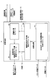
- FIG. 1 is a diagram showing an example of a laser sensor in one embodiment.
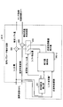
- the laser sensor shown in FIG. 1 has a sensor body 1 and a computer 4.
- the sensor main body 1 includes a light emitting unit 2, a light receiving unit 3, and an arithmetic circuit 5.
- the floodlight unit 2 includes an angle of view parameter correction circuit 20, a sensor drive control circuit 21, a laser drive circuit 22, a laser diode 23, a 2-axis scanning mirror 24, a 2-axis mirror controller 25, and a floodlight lens 26.
- the laser diode 23 is an example of a laser light source.
- the two-axis scanning mirror 24 can be formed by, for example, a two-dimensional MEMS (Micro Electro Mechanical System) mirror.
- the angle of view parameter correction circuit 20 corrects the angle of view parameter (or angle of view control amount) including the scanning angle range and the shift amount output by the arithmetic circuit 5 to the sensor drive control circuit 21. Supply.
- the sensor drive control circuit 21 supplies the laser drive circuit 22 with a light emission timing signal indicating the light emission timing of the laser diode 23.
- the laser drive circuit 22 causes the laser diode 23 to emit light at the light emission timing indicated by the light emission timing signal. Further, the sensor drive control circuit 21 supplies a drive control signal for driving the scanning mirror 24 on two axes to the mirror controller 25.
- the mirror controller 25 outputs a drive signal for driving the scanning mirror 24 on two axes according to the drive control signal, and drives the scanning mirror 24 with a well-known drive unit (not shown). For example, a sinusoidal drive signal (for example, a drive current), which is an example of a non-linear waveform, is used for driving the scanning mirror 24 in the horizontal direction, and a vertical driving signal orthogonal to the horizontal direction of the scanning mirror 24 is used for driving the scanning mirror 24 in the vertical direction.
- a sinusoidal drive signal for example, a drive current
- a vertical driving signal orthogonal to the horizontal direction of the scanning mirror 24 is used for driving the scanning mirror 24 in the vertical direction.
- a sawtooth drive signal (eg, drive current), which is an example of a linear waveform, is used.
- the mirror controller 25 includes an LPF 250 for suppressing the generation of vibration due to resonance point excitation in the sharp angle portion of the upper and lower ends of the sawtooth wave for driving the sawtooth wave used for driving the scanning mirror 24 in the vertical direction.
- the sawtooth drive signal used to drive the scanning mirror 24 in the vertical direction drives the scanning mirror 24 through the LPF 250. Therefore, the generation of vibration due to the excitation of the resonance point is suppressed, and the high frequency component is removed due to the characteristics of the LPF250.
- a linear waveform drive signal may be used to drive the scanning mirror 24 in the horizontal direction
- a non-linear waveform drive signal may be used to drive the scanning mirror 24 in the vertical direction.
- the horizontal direction is an example of the first direction
- the vertical direction is an example of the second direction orthogonal to the horizontal direction (first direction).
- the laser sensor may have an arbitrary angular arrangement with respect to a horizontal plane, for example.
- the mirror angle of the scanning mirror 24 is detected by a well-known detection unit (not shown), and an angle signal indicating the mirror angle is supplied to the mirror controller 25.
- the scanning mirror 24 is shown in a form including the driving unit and the detecting unit.
- the mirror controller 25 generates mirror angle data representing the mirror angle of the scanning mirror 24 according to the angle signal and supplies the mirror angle data to the arithmetic circuit 5.
- the laser light emitted from the laser diode 23 is reflected (or deflected) by the scanning mirror 24, and scans the scanning angle range through the projectile lens 26, for example, raster scanning.
- the laser beam (or laser pulse) scans the measurement range at a position separated from the sensor body 1 by a certain distance.
- This measurement range has a width corresponding to a distance in which the laser beam moves from one end to the other end of the scanning angle range, for example, substantially parallel to the horizontal plane (or the ground) at a position separated from the sensor body 1 by a certain distance.
- this measurement range is a height corresponding to the distance that the laser beam moves from the lowest point to the highest point of the scanning angle range in the vertical direction orthogonal to the horizontal plane at a position separated from the sensor body 1 by a certain distance.
- the measurement range refers to the entire region scanned by the laser beam at a position separated from the sensor body 1 by a certain distance. Therefore, when the emission timing of the laser beam is constant, the shorter the distance from the sensor body 1, the narrower the measurement range and the denser the sampling density within the measurement range. On the other hand, when the emission timing of the laser beam is constant, the longer the distance from the sensor body 1, the wider the measurement range and the coarser the sampling density within the measurement range.
- the light receiving unit 3 includes a light receiving lens 31, a photodetector 32, and a distance measuring circuit 33.
- the reflected light from the measurement target 100 is detected by the photodetector 32 via the light receiving lens 31.
- the photodetector 32 supplies a light receiving signal representing the detected reflected light to the distance measuring circuit 33.
- the distance measurement circuit 33 measures the round-trip time (TOF: TimeOfFlight) ⁇ T from when the laser beam is emitted from the light projecting unit 2 until the laser beam is reflected by the measurement target 100 and returned to the light receiving unit 3. To do.
- the distance measurement circuit 33 optically measures the distance to the measurement target 100, and supplies the distance data indicating the measured distance to the calculation circuit 5.
- the speed of light is expressed in c (about 300,000 km / s)
- the distance to the measurement target 100 can be obtained from, for example, (c ⁇ ⁇ T) / 2.
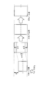
- FIG. 2 is a functional block diagram showing an example of the arithmetic circuit shown in FIG.
- the arithmetic circuit 5 can be formed by, for example, a processor.
- the processor can execute the functions of the modules 51 to 54 shown in FIG. 2 by executing the program stored in the memory.
- the arithmetic circuit 5 has a three-dimensional data and distance image generation module 51, a distance measurement module 52, a scanning angle range and shift amount calculation module 53, and an image processing and target extraction module 54.
- the arithmetic circuit 5 is an example of a changing means for changing the measurement range so that the sampling density becomes a certain value or more according to the measured distance to the measurement target and the detected orientation of the measurement target.
- Changing the measurement range means expanding or narrowing the size of the measurement range.
- the size of the measurement range is widened by widening the width of the scanning angle range, and narrowed by narrowing the width of the scanning angle range.
- the three-dimensional data and distance image generation module 51 inputs mirror angle data and distance data, generates a distance image from the distance data, and generates three-dimensional data from the distance image and the mirror angle data. This is an example. Further, the three-dimensional data and the distance image generation module 51 generates the projection angle data indicating the projection angle of the laser beam from the mirror angle data.
- the distance image is an image in which the distance values at each AF point are arranged in the order of the samples scanned by the raster.
- the three-dimensional data can be generated by converting using the distance value and the projection angle data.
- the three-dimensional data can be output to the computer 4. Similarly, the distance image can also be output to the computer 4.
- the image processing and target extraction module 54 is an example of a target extraction means that extracts data of the measurement target 100 from this distance image when the measurement target 100 exists within the scanning angle range scanned by the raster.
- the method for extracting the measurement target 100 from the distance image is not particularly limited, and for example, the measurement target 100 can be extracted by a well-known method. For example, if the measurement target 100 is a human being, the measurement target 100 can be extracted by detecting a shape such as a posture that the human can take from a distance image. Further, as another example of target designation, there is also an extraction method in which the acquired distance image or three-dimensional image is displayed on a display, and a desired position of the screen is designated (clicked) or a range is designated with a mouse or the like.
- the image processing and target extraction module 54 supplies the projection angle data, the distance data, and the extracted data of the measurement target 100 (hereinafter, also referred to as “target data”) to the distance measurement module 52, and scans the target data. It is supplied to the angle range and shift amount calculation module 53.
- the distance measurement module 52 calculates the distance from the extracted target data to the position of the center of gravity of the measurement target 100, and from the projection angle data and the extracted target data, determines the azimuth angle of the measurement target 100 to, for example, the position of the center of gravity.
- This is an example of a first calculation means (or a first calculation unit) for calculation.
- the method for calculating the center of gravity of the measurement target 100 is not particularly limited, and for example, it can be calculated by a well-known method. Further, the method of calculating the azimuth angle up to the measurement target 100 is not particularly limited, and for example, it can be calculated by a well-known method.
- the scanning angle range and shift amount calculation module 53 calculates the set values of the scanning angle range and the shift amount of the scanning angle range based on the distance to the center of gravity position of the measurement target 100 and the azimuth angle.
- the set values of the scanning angle range and the shift amount of the scanning angle range are desired sampling intervals (that is, sampling densities) input from the computer 4 in advance, and the measurement target 100 is detected near the center of the scanning angle range. Calculate to be done.
- the scanning angle range and shift amount calculation module 53 detects the set values of the scanning angle range and the shift amount based on the distance to the center of gravity position of the measurement target 100 and the azimuth angle when the measurement target 100 is near the center of the scanning angle range.
- the scanning angle range and shift amount calculation module 53 supplies the set values to the sensor drive control circuit 21 and proceeds to the next measurement. By shifting the scanning angle range, the center of the scanning angle range can be shifted to change the area covered by the scanning angle range.
- the scanning angle range and shift amount calculation module 53 sets the mirror drive conditions for supplying the drive control signal for driving the scanning mirror 24 on two axes to the mirror controller 25 via the angle of view parameter correction circuit 20 as a sensor drive control circuit. It is an example of the setting means to set to 21.
- the arithmetic circuit 5 measures even if the distance to the measurement target 100 changes, the interval (that is, the sampling interval) of the sampling points (or the distance measuring points) by the laser beam is a certain value or more. Can be done.
- the sampling interval is also referred to as "sampling density" below.
- the measurement distance becomes short and the scanning angle range exceeds the maximum scanning angle range (that is, the maximum operating angle range of the scanning mirror 24)
- the measurement can be performed in the maximum scanning angle range.
- the shift amount of the scanning angle range becomes large and one side of the scanning angle range exceeds the corresponding side of the maximum operating angle range (that is, the operating limit)
- the position of the operating limit of the maximum operating angle range is prioritized.
- the shift amount can be reduced.
- the image processing and target extraction module 54 does not output the target data.
- the scanning angle range and shift amount calculation module 53 may reset the scanning angle range to, for example, the maximum scanning angle range, and perform scanning according to the maximum scanning angle range.
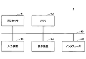
- the computer 4 may have, for example, the configuration shown in FIG. FIG. 3 is a block diagram showing an example of a computer.
- the computer 4 shown in FIG. 3 has a processor 41 connected to each other via a bus 40, a memory 42, an input device 43, a display device 44, and an interface (or communication device) 45.
- the processor 41 can be formed by, for example, a central processing unit (CPU: Central Processing Unit) or the like, executes a program stored in the memory 42, and controls the entire computer 4.
- the memory 42 is formed of a computer-readable storage medium including a non-transitory computer-readable storage medium such as a semiconductor storage device, a magnetic recording medium, an optical recording medium, a photomagnetic recording medium, and the like. It is possible.
- the memory 42 stores various programs including a distance measurement program executed by the processor 41, various data, and the like.
- the input device 43 can be formed by a user (or an operator), for example, a keyboard or the like, and is used to input commands and data to the processor 41.
- the display device 44 displays a message to the user, a measurement result of the distance measurement process, and the like.
- the interface 45 connects the computer 4 so as to be able to communicate with another computer or the like. In this example, the computer 4 is connected to the arithmetic circuit 5 via the interface 45.
- the computer 4 is not limited to a hardware configuration in which the components of the computer 4 are connected via the bus 40.
- a general-purpose computer may be used for the computer 4, for example, a general-purpose computer may be used.
- the input device 43 and the display device 44 of the computer 4 can be omitted. Further, in the case of a module, a semiconductor chip, or the like in which the interface 45 of the computer 4 is further omitted, the output of the sensor body 1 (that is, the output of the arithmetic circuit 5) is directly connected to the processor 41 even if it is connected to the bus 40. Is also good.
- the computer 4 when the computer 4 is made of a semiconductor chip or the like, the semiconductor chip or the like may be provided in the sensor main body 1.
- the computer 4 may include, for example, an arithmetic circuit 5.
- the computer 4 that is, the processor 41 and the memory 42
- the three-dimensional data and distance image generation module 51 of the arithmetic circuit 5 of the laser sensor generates a distance image and three-dimensional data, it is sometimes called a three-dimensional (3D: 3-Dimensional) sensor.
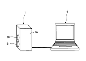
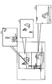
- FIG. 4 is a diagram showing an example of the housing of the sensor body.
- FIG. 4 shows an example in which the sensor body 1 of the distance measuring device is connected to a computer 4 formed of a personal computer (PC) for convenience of explanation.
- the sensor main body 1 has a housing 1A, and the light projecting unit 2, the light receiving unit 3, and the arithmetic circuit 5 are housed in the housing 1A.
- the light projecting lens 26 of the light projecting unit 2 and the light receiving lens 31 of the light receiving unit 3 are arranged on one side surface of the housing 1A.
- the computer 4 may be separate from the laser sensor.
- the laser sensor has only the sensor body 1, and the computer 4 may be formed by, for example, a cloud computing system.
- the angle of view parameter correction circuit 20, the sensor drive control circuit 21, and the mirror controller 25 may be formed by a processor forming the arithmetic circuit 5.
- the computer 4 may further execute at least a part of the processing of the arithmetic circuit 5, the angle of view parameter correction circuit 20, the sensor drive control circuit 21, and the mirror controller 25.
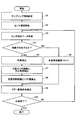
- FIG. 5 is a flowchart illustrating an example of the distance measurement process in the first embodiment.
- the computer 4 starts the distance measurement process and sets the setting data including the sampling interval (sampling density).
- the computer 4 starts the measurement by the sensor main body 1.
- step S3 the three-dimensional data of the arithmetic circuit 5 and the distance image generation module 51 acquire the measurement data from the sensor main body 1.
- the measurement data to be acquired includes the distance data from the distance measurement circuit 33 and the mirror angle data from the mirror controller 35. Therefore, in step S3, the three-dimensional data and distance image generation module 51 generates three-dimensional data from the distance data, generates a distance image from the three-dimensional data, and generates projection angle data from the mirror angle data.
- the three-dimensional data can be output to the computer 4 as needed.
- step S4 the image processing and target extraction module 54 of the arithmetic circuit 5 determines whether or not the measurement target 100 exists within the scanning angle range scanned by the raster, and if the determination result is NO, the processing is performed in step S5. If the determination result is YES, the process proceeds to step S6. Whether or not the measurement target 100 exists within the scanning angle range scanned by the raster can be determined by a well-known method.
- step S5 since the target data is not output from the image processing and target extraction module 54, the scanning angle range and shift amount calculation module 53 of the arithmetic circuit 5 reset the scanning angle range to the maximum scanning angle range, and the processing will be described later. Proceed to step S9.
- step S6 the image processing and target extraction module 54 of the arithmetic circuit 5 extracts the measurement target 100 from the distance image when the measurement target 100 exists within the scanning angle range scanned by the raster, and the extracted measurement is performed. The target data of the target 100 is obtained.
- step S7 the distance measurement module 52 of the arithmetic circuit 5 calculates the distance and the azimuth angle from the extracted target data and the projection angle data to the position of the center of gravity of the measurement target 100, and stores them as necessary.
- step S8 the scanning angle range and shift amount calculation module 53 of the arithmetic circuit 5 are input in advance from the computer 4 based on the distance to the center of gravity position and the azimuth angle of the measurement target 100 calculated or stored in step S7.
- the set values of the scanning angle range and the shift amount of the scanning angle range are calculated so as to obtain the desired sampling density.
- step S9 the sensor drive control circuit 21 sets the mirror drive conditions for the scanning angle range and shift amount calculation module 53 of the arithmetic circuit 5 to supply the drive control signal for driving the scanning mirror 24 on two axes to the mirror controller 25.
- the scanning angle range and shift amount calculation module 53 supplies the calculated scanning angle range and the set values of the shift amount in the scanning angle range to the sensor drive control circuit 21.
- the mirror drive condition is set in step S9 based on the reset scanning angle range.
- step S10 the computer 4 determines whether or not the distance measurement process has been completed. If the determination result is NO, the process returns to step S3, and if the determination result is YES, the process ends. Therefore, by repeating the above processing until the determination result in step S10 becomes YES, it is possible to perform measurement with a sampling interval of a certain value or longer even if the distance to the measurement target 100 changes.
- the distance to the measurement target can be measured at a constant or higher sampling density within the measurement range. This makes it possible to meet both the demand for widening the measurement range and stable high-precision measurement, and the demand for high-resolution measurement with a dense sampling density within the measurement range. Become.
- FIG. 6 is a functional block diagram showing an example of the angle of view parameter correction circuit in the first embodiment.
- the angle of view parameter correction circuit 20-1 shown in FIG. 6 includes an angle of view change detection unit 201, a correction amount reference table unit 202-1, a switching circuit 203, and addition circuits 204 and 205.
- the shift amount from the arithmetic circuit 5 shown in FIG. 1 is input to the angle of view change detection unit 201 and the addition circuit 204. Further, the scanning angle range from the arithmetic circuit 5 is input to the addition circuit 205.
- the angle of view change detection unit 201 detects an angle of view change from the shift amount, it supplies a signal indicating the first frame immediately after the change (hereinafter, also referred to as “the first frame after the change”) to the switching circuit 203 and shifts.
- the change amount is supplied to the correction amount reference table unit 202-1.
- the angle of view change detection unit 201 changes the angle of view based on the shift amount among the angle of view parameters including the scanning angle range and the shift amount of the scanning angle range, which are set based on the distance to the measurement target 100 and the azimuth angle.
- This is an example of an angle-of-view change detecting means (or an angle-of-view changing unit) for detecting an angle of view.
- the angle of view change detecting means outputs a signal indicating the first frame immediately after the change and a shift change amount.
- the shift amount in the scanning angle range is the shift amount in the vertical direction.
- the correction amount reference table unit 202-1 has, for example, a reference table and an interpolation unit, refers to the reference table based on the shift change amount, and corrects the shift correction amount and the scanning angle range corresponding to the assumed deviation amount d in the first frame. The amount is read out and supplied to the switching circuit 203.
- the correction amount reference table unit 202-1 uses at least the shift change amount to generate a shift correction amount and a scanning angle range correction amount corresponding to the assumed deviation amount d in the first frame. This is an example of the generator).
- the interpolation unit linearly interpolates using the front and rear shift change amounts. The corresponding shift correction amount and scanning angle range correction amount are obtained by the above means.
- the switching circuit 203 supplies the shift correction amount to the addition circuit 204 and the scanning angle range correction amount to the addition circuit 205 in response to the signal indicating the first frame after the change.
- the addition circuit 204 outputs a correction shift amount obtained by adding the shift amount and the shift correction amount to the sensor drive control circuit 21.
- the addition circuit 205 outputs the corrected scanning angle range obtained by adding the scanning angle range and the scanning angle range correction amount to the sensor drive control circuit 21 shown in FIG.
- the switching circuit 203 and the addition circuits 204 and 205 respond to the signal indicating the first frame after the change, and in the first frame, the angle-of-view parameter correction that outputs the correction angle-of-view parameter including the correction shift amount and the correction scanning angle range.
- the angle-of-view parameter correction means includes a correction shift amount in which the shift amount is corrected by the shift correction amount in the first frame, and a correction scanning angle range in which the scanning angle range is corrected by the scanning angle range correction amount. Output the angle of view parameter.
- the angle-of-view parameter correction means outputs the angle-of-view parameter including the shift amount and the scanning angle range in the second and subsequent frames.
- the sensor drive control circuit 21 and the mirror controller 25 shown in FIG. 1 generate and drive a first drive signal having a non-linear waveform that rotationally drives the scanning mirror 24 in the horizontal direction (or drive). Part) is an example.
- the drive means generates a second drive signal having a linear waveform that rotationally drives the scanning mirror 24 in the vertical direction based on the output of the angle of view parameter correction means, and drives the scanning mirror 24 through the LPF 250 of the mirror controller 25.
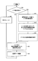
- FIG. 7 is a flowchart illustrating an example of processing of the angle of view parameter correction circuit 20-1, the sensor drive control circuit 21, and the mirror controller 25 in the first embodiment.
- the angle of view parameter correction circuit 20-1 can be formed by, for example, a processor. By executing the program stored in the memory, the processor can execute the functions of each part 201, 202-1, 203 to 205 shown in FIG.
- step S21 the processor executes the function of the angle of view change detection unit 201 to determine whether or not the shift amount from the arithmetic circuit 5 has changed. If the determination result in step S21 is YES, the process proceeds to step S22, and if the determination result in step S21 is NO, the process proceeds to step S25, which will be described later.
- step S22 the processor executes the function of the angle of view change detection unit 201, supplies a signal indicating the first frame after the change to the switching circuit 203, and calculates the shift change amount from the shift amount before and after the change.
- step S23-1 the processor executes the function of the correction amount reference table unit 202-1 and uses the shift change amount to refer to the shift correction amount and the scanning angle range correction amount corresponding to the assumed deviation amount in the first frame. Obtain from the table.
- step S24 the processor realizes the function of the switching circuit 203, and supplies the shift correction amount and the scanning angle range correction amount to the addition circuits 204 and 205 in response to the signal indicating the first frame after the change, and the angle of view. Modify the parameters.
- the addition circuit 204 outputs a correction shift amount obtained by adding the shift amount and the shift correction amount
- the addition circuit 205 outputs a correction scanning angle range obtained by adding the scanning angle range and the scanning angle range correction amount.
- step S25 the sensor drive control circuit 21 generates a drive control signal of the drive waveform according to the correction shift amount and the correction scanning angle range from the addition circuits 204 and 205.
- step S26 the mirror controller 25 drives the scanning mirror 24 with the driving signal of the sawtooth wave used for driving the scanning mirror 24 in the vertical direction according to the driving control signal.
- the sine wave drive signal used for driving the scanning mirror 24 in the horizontal direction is not subject to correction by the angle of view parameter correction circuit 20-1, and thus the description thereof will be omitted.
- step S27 the processor executes the function of the angle of view change detection unit 201 to acquire the shift amount of the next frame from the arithmetic circuit 5, and the process returns to step S21.
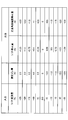
- FIG. 8 is a diagram showing an example of a reference table.
- the reference table has a shift change amount (%) which is an example of input, an assumed deviation amount (%) of the first frame, a shift correction amount (%) which is an example of output, and a scanning angle.
- the range correction amount (%) is stored.
- the shift change amount, the assumed shift amount, the shift correction amount, and the scanning angle range correction amount of the reference table are preliminarily under the condition that only the shift amount changes, and neither the scanning angle range nor the cutoff frequency of the LPF250 changes. It is possible to calculate.
- the assumed deviation amount changes according to the cutoff frequency and the shift amount of the LPF250.
- FIG. 9 is a diagram illustrating an example of a measurement range in the vertical direction.
- the measurement target 100 is a gymnast who performs a vaulting horse, and the angle of view is changed according to the movement of the gymnast.
- ST C indicates the measurement range in the angle of view of the standards, the measuring range that has moved upward about the ST C shown in ST U, the measurement range has been moved downward about the ST C in ST D Shown.
- gymnast measurement range ST C started is acting vaulting horse
- gymnast measurement range ST U is jumped vaulting horse
- gymnast measurement range ST D are landed.
- FIG. 10 is a diagram illustrating a process when the measurement range is moved downward.
- FIG. 10 corresponds to the case where the measurement range is moved from ST C to ST D in FIG. 9, for example.
- the angle of view parameters that is, the scanning angle range and the shift amount are changed as shown in FIG. 10 only for the first frame immediately after the movement of the measurement range.
- the entire measurement range of the first frame is offset downward by d / 2 (deg)
- the vertical height is narrowed by d (deg).
- the angle of view can be controlled equally between the first frame immediately after the movement of the measurement range and the second and subsequent frames.
- FIG. 11 is a diagram illustrating processing when the measurement range is moved upward.
- Figure 11 corresponds to the case where, for example, the measurement range in Fig. 9 has moved from ST C to ST U.
- the assumed deviation amount is d (deg)
- the angle of view parameters that is, the scanning angle range and the shift amount are changed as shown in FIG. 11 only for the first frame immediately after the movement of the measurement range.
- the entire measurement range of the first frame is offset upward by d / 2 (deg), and the vertical height is widened by d (deg).
- the angle of view can be controlled equally between the first frame immediately after the movement of the measurement range and the second and subsequent frames.
- FIG. 12 is a functional block diagram showing an example of the angle of view parameter correction circuit in the second embodiment.
- the angle of view parameter correction circuit 20-2 shown in FIG. 12 includes an angle of view change detection unit 201, a correction amount calculation unit 202-2, a switching circuit 203, and addition circuits 204 and 205.
- the shift amount from the arithmetic circuit 5 shown in FIG. 1 is input to the angle of view change detection unit 201 and the addition circuit 204. Further, the scanning angle range from the arithmetic circuit 5 is input to the correction amount calculation unit 202-2 and the addition circuit 205.
- the angle of view change detection unit 201 detects an angle of view change from the shift amount, it supplies a signal indicating the first frame after the change to the switching circuit 203 and supplies the shift change amount to the correction amount calculation unit 202-2.
- the correction amount calculation unit 202-2 corrects the shift correction amount and the scanning angle range corresponding to the assumed deviation amount d of the first frame obtained from the shift change amount, the scanning angle range, and the cutoff frequency of the LPF250 of the mirror controller 25.
- the amount is calculated and supplied to the switching circuit 203.
- the correction amount calculation unit 202-2 uses the shift change amount, the scanning angle range, and the cutoff frequency of the LPF250 to generate a correction amount and a scanning angle range correction amount corresponding to the assumed deviation amount d in the first frame. This is an example of a quantity generating means.
- the switching circuit 203 supplies the shift correction amount to the addition circuit 204 and the scanning angle range correction amount to the addition circuit 205 in response to the signal indicating the first frame after the change.
- the addition circuit 204 outputs a correction shift amount obtained by adding the shift amount and the shift correction amount to the sensor drive control circuit 21.
- the addition circuit 205 outputs the corrected scanning angle range obtained by adding the scanning angle range and the scanning angle range correction amount to the sensor drive control circuit 21 shown in FIG.
- the contents of the reference table are calculated in advance under the condition that only the shift amount changes and neither the scanning angle range nor the cutoff frequency of the LPF 250 of the mirror controller 25 changes. It is possible to keep it.
- the shift correction amount and the scanning angle range correction amount are calculated when the angle of view is dynamically changed as in this embodiment. Just do it.
- FIG. 13 is a flowchart illustrating an example of processing of the angle of view parameter correction circuit 20-2, the sensor drive control circuit 21, and the mirror controller 25 in the second embodiment.
- the angle of view parameter correction circuit 20-2 can be formed by, for example, a processor.
- the processor can execute the functions of each part 201, 202-2, 203 to 205 shown in FIG. 12 by executing the program stored in the memory.
- step S21 the processor executes the function of the angle of view change detection unit 201 to determine whether or not the shift amount from the arithmetic circuit 5 has changed. If the determination result in step S21 is YES, the process proceeds to step S22, and if the determination result in step S21 is NO, the process proceeds to step S25, which will be described later.
- step S22 the processor executes the function of the angle of view change detection unit 201, supplies a signal indicating the first frame after the change to the switching circuit 203, and calculates the shift change amount from the shift amount before and after the change.
- step S23-2 the processor executes the function of the correction amount calculation unit 202-2.
- the shift correction amount and the scanning angle range correction amount corresponding to the assumed deviation amount d of the first frame obtained by the processor from the shift change amount, the scanning angle range, and the cutoff frequency of the LPF250 of the mirror controller 25. Is calculated.
- the processor realizes the function of the switching circuit 203, and supplies the shift correction amount and the scanning angle range correction amount to the addition circuits 204 and 205 in response to the signal indicating the first frame after the change, and the angle of view. Modify the parameters.
- the addition circuit 204 outputs a correction shift amount obtained by adding the shift amount and the shift correction amount
- the addition circuit 205 outputs a correction scanning angle range obtained by adding the scanning angle range and the scanning angle range correction amount.
- step S25 the sensor drive control circuit 21 generates a drive control signal of the drive waveform according to the correction shift amount and the correction scanning angle range from the addition circuits 204 and 205.
- step S26 the mirror controller 25 drives the scanning mirror 24 with the driving signal of the sawtooth wave used for driving the scanning mirror 24 in the vertical direction according to the driving control signal.
- the sine wave drive signal used for driving the scanning mirror 24 in the horizontal direction is not subject to correction by the angle of view parameter correction circuit 20-2, and thus the description thereof will be omitted.
- step S27 the processor executes the function of the angle of view change detection unit 201 to acquire the shift amount of the next frame from the arithmetic circuit 5, and the process returns to step S21.
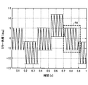
- FIG. 14 is a diagram illustrating an example of vertical movement of the measurement range when the angle of view parameter is not modified.
- the vertical axis represents the vertical mirror angle of the scanning mirror 24 in degrees (deg)
- the horizontal axis represents time in seconds (s).
- E1 indicates an assumed deviation amount that occurs in the first frame immediately after moving the measurement range in the vertical direction.
- FIG. 15 is a diagram illustrating a time when the measurement range is moved downward when the angle of view parameter is not modified.
- the vertical axis represents the vertical mirror angle of the scanning mirror 24 in degrees (deg)
- the horizontal axis represents time in seconds (s).
- FIG. 15 shows an enlarged portion R1 surrounded by a thick broken line in FIG. Further, F1 indicates an angle of view that changes only in the first frame immediately after moving the measurement range in the vertical direction.
- FIG. 16 is a diagram illustrating an example of vertical movement of the measurement range when the angle of view parameter is modified.
- the vertical axis represents the vertical mirror angle of the scanning mirror 24 in degrees (deg)
- the horizontal axis represents time in seconds (s).
- the assumed deviation amount E1 as shown in FIG. 14 does not occur in the first frame immediately after moving the measurement range in the vertical direction.
- FIG. 17 is a diagram for explaining the downward movement of the measurement range when the angle of view parameter is modified.
- the vertical axis represents the vertical mirror angle of the scanning mirror 24 in degrees (deg)
- the horizontal axis represents time in seconds (s).
- FIG. 17 shows an enlarged portion R2 surrounded by a thick broken line in FIG.
- the angles of view are the same in the first frame immediately after moving the measurement range in the vertical direction and in the second and subsequent frames.
- the angle of view parameters including the scanning angle range and the shift amount determined according to the position of the measurement target are acquired.
- the correction amount for adjustment including the scanning angle range correction amount and the shift correction amount to be applied to the first frame in which the angle of view is changed is determined.
- the angle of view parameter is corrected by the correction amount for adjustment, that is, the correction scanning angle range and the correction shift amount obtained by correcting the scanning angle range and the shift amount by the scanning angle range correction amount and the shift correction amount, respectively.
- the scanning mirror is controlled by applying the angle of view parameters including the scanning angle range and the shift amount.
- the scanning mirror is controlled by applying the angle of view parameters including the scanning angle range and the shift amount.
- the position and size of the measurement target in the predetermined direction do not change between the first frame and the second and subsequent frames. It is possible to suppress a decrease in the measurement accuracy of the laser sensor for a measurement target having a high speed.
- the laser sensor can be applied to scoring support systems, in-vehicle systems, etc.
- An example of a scoring support system supports scoring, for example, gymnastics performances based on the output of a laser sensor.
- the measurement target 100 is a gymnast
- scoring can be performed by, for example, the computer 4 shown in FIG. 1 executing a scoring program.
- the computer 4 may acquire the skeleton information of the gymnast by a well-known method based on the three-dimensional data from the arithmetic circuit 5 and the distance image. Since the skeletal information of the gymnast includes the three-dimensional position of each joint of the gymnast in each frame, it is possible to recognize the gymnastics technique from the skeletal information and score the gymnastics performance from the degree of completion of the technique. ..
- the movement speed of the gymnast is fast, and it is necessary to move the angle of view of the laser sensor according to the position of the gymnast.
- the angle of view can be controlled equally between the first frame immediately after the movement and the second and subsequent frames, so that the first frame and the second frame can be controlled equally.
- the vertical position and size of the gymnast does not change after the eyes.
- the reliability of the scoring support system can be improved.
- An example of an in-vehicle system recognizes, for example, the position, type, etc. of the measurement target 100 in front of the vehicle based on the output of the laser sensor.
- the type of the measurement target 100 includes a pedestrian, another vehicle, and the like, and the measurement target 100 can be recognized by, for example, the computer 4 shown in FIG. 1 executing a recognition program.
- the computer 4 may acquire the shape information of the measurement target 100 by a well-known method based on the three-dimensional data and the distance image from the arithmetic circuit 5. Since the shape information of the measurement target 100 includes the three-dimensional positions of each part of the measurement target 100 in each frame, the position, type, etc.
- the laser sensor When the laser sensor is applied to an in-vehicle system, the laser sensor itself moves together with the vehicle on which the laser sensor itself is mounted, so that the relative moving speed of the measurement target 100 may be high. However, even for the measurement target 100 having a high relative moving speed, according to each of the above embodiments, it is possible to suppress a decrease in the measurement accuracy of the laser sensor, so that the position, type, etc. of the measurement target 100 are high. It can be recognized accurately and the reliability of the in-vehicle system can be improved.
Landscapes
- Physics & Mathematics (AREA)
- Engineering & Computer Science (AREA)
- General Physics & Mathematics (AREA)
- Computer Networks & Wireless Communication (AREA)
- Radar, Positioning & Navigation (AREA)
- Remote Sensing (AREA)
- Electromagnetism (AREA)
- Optics & Photonics (AREA)
- Optical Radar Systems And Details Thereof (AREA)
- Measurement Of Optical Distance (AREA)
Priority Applications (5)
| Application Number | Priority Date | Filing Date | Title |
|---|---|---|---|
| PCT/JP2019/038759 WO2021064863A1 (ja) | 2019-10-01 | 2019-10-01 | レーザセンサ、ミラー制御方法、及びプログラム |
| CN201980100914.6A CN114467035A (zh) | 2019-10-01 | 2019-10-01 | 激光传感器、反射镜控制方法以及程序 |
| JP2021550813A JP7283560B2 (ja) | 2019-10-01 | 2019-10-01 | レーザセンサ、ミラー制御方法、及びプログラム |
| EP19947657.3A EP4040185A4 (en) | 2019-10-01 | 2019-10-01 | LASER SENSOR, MIRROR CONTROL METHOD AND PROGRAM |
| US17/700,333 US20220206251A1 (en) | 2019-10-01 | 2022-03-21 | Mirror control device, mirror control method, and storage medium |
Applications Claiming Priority (1)
| Application Number | Priority Date | Filing Date | Title |
|---|---|---|---|
| PCT/JP2019/038759 WO2021064863A1 (ja) | 2019-10-01 | 2019-10-01 | レーザセンサ、ミラー制御方法、及びプログラム |
Related Child Applications (1)
| Application Number | Title | Priority Date | Filing Date |
|---|---|---|---|
| US17/700,333 Continuation US20220206251A1 (en) | 2019-10-01 | 2022-03-21 | Mirror control device, mirror control method, and storage medium |
Publications (1)
| Publication Number | Publication Date |
|---|---|
| WO2021064863A1 true WO2021064863A1 (ja) | 2021-04-08 |
Family
ID=75337847
Family Applications (1)
| Application Number | Title | Priority Date | Filing Date |
|---|---|---|---|
| PCT/JP2019/038759 Ceased WO2021064863A1 (ja) | 2019-10-01 | 2019-10-01 | レーザセンサ、ミラー制御方法、及びプログラム |
Country Status (5)
| Country | Link |
|---|---|
| US (1) | US20220206251A1 (cg-RX-API-DMAC7.html) |
| EP (1) | EP4040185A4 (cg-RX-API-DMAC7.html) |
| JP (1) | JP7283560B2 (cg-RX-API-DMAC7.html) |
| CN (1) | CN114467035A (cg-RX-API-DMAC7.html) |
| WO (1) | WO2021064863A1 (cg-RX-API-DMAC7.html) |
Cited By (1)
| Publication number | Priority date | Publication date | Assignee | Title |
|---|---|---|---|---|
| CN113971705A (zh) * | 2021-09-13 | 2022-01-25 | 沈阳先进医疗设备技术孵化中心有限公司 | 图像重建方法、装置及设备 |
Families Citing this family (1)
| Publication number | Priority date | Publication date | Assignee | Title |
|---|---|---|---|---|
| CN118162742A (zh) * | 2024-03-18 | 2024-06-11 | 武汉锐科光纤激光技术股份有限公司 | 激光扫描幅面校准方法、装置及相关设备 |
Citations (6)
| Publication number | Priority date | Publication date | Assignee | Title |
|---|---|---|---|---|
| JP2010092018A (ja) * | 2008-09-10 | 2010-04-22 | Nippon Signal Co Ltd:The | アクチュエータの駆動装置 |
| JP2011154312A (ja) * | 2010-01-28 | 2011-08-11 | Nikon Corp | レーザ走査型顕微鏡および制御方法 |
| JP2011180294A (ja) | 2010-02-26 | 2011-09-15 | Shinano Kenshi Co Ltd | 光走査装置の駆動制御装置 |
| JP2013205770A (ja) | 2012-03-29 | 2013-10-07 | Kyocera Document Solutions Inc | 光走査装置及び画像形成装置 |
| JP2017181209A (ja) | 2016-03-29 | 2017-10-05 | 富士通株式会社 | 距離測定装置、距離測定方法及びプログラム |
| WO2019069369A1 (ja) * | 2017-10-03 | 2019-04-11 | 富士通株式会社 | 姿勢認識システム、画像補正プログラムおよび画像補正方法 |
Family Cites Families (7)
| Publication number | Priority date | Publication date | Assignee | Title |
|---|---|---|---|---|
| JP5769941B2 (ja) * | 2010-09-10 | 2015-08-26 | 日本信号株式会社 | アクチュエータの駆動装置 |
| US10078132B2 (en) * | 2013-04-11 | 2018-09-18 | Konica Minolta, Inc. | Scanning optical system and radar |
| US9897689B2 (en) * | 2014-08-15 | 2018-02-20 | Aeye, Inc. | Method and system for ladar transmission with interline skipping for dynamic scan patterns |
| CN110286388B (zh) * | 2016-09-20 | 2020-11-03 | 创新科技有限公司 | 激光雷达系统和使用其检测物体的方法及介质 |
| US11137498B2 (en) * | 2018-02-12 | 2021-10-05 | Microvision, Inc. | Scanning rangefinding system with variable field of view |
| JP7011164B2 (ja) * | 2018-03-15 | 2022-02-10 | ミツミ電機株式会社 | アクチュエータ及び光走査装置 |
| CN109270515B (zh) * | 2018-11-29 | 2020-06-16 | 北京理工大学 | 可变扫描区域同轴收发扫描激光雷达 |
-
2019
- 2019-10-01 CN CN201980100914.6A patent/CN114467035A/zh active Pending
- 2019-10-01 EP EP19947657.3A patent/EP4040185A4/en not_active Withdrawn
- 2019-10-01 JP JP2021550813A patent/JP7283560B2/ja active Active
- 2019-10-01 WO PCT/JP2019/038759 patent/WO2021064863A1/ja not_active Ceased
-
2022
- 2022-03-21 US US17/700,333 patent/US20220206251A1/en not_active Abandoned
Patent Citations (6)
| Publication number | Priority date | Publication date | Assignee | Title |
|---|---|---|---|---|
| JP2010092018A (ja) * | 2008-09-10 | 2010-04-22 | Nippon Signal Co Ltd:The | アクチュエータの駆動装置 |
| JP2011154312A (ja) * | 2010-01-28 | 2011-08-11 | Nikon Corp | レーザ走査型顕微鏡および制御方法 |
| JP2011180294A (ja) | 2010-02-26 | 2011-09-15 | Shinano Kenshi Co Ltd | 光走査装置の駆動制御装置 |
| JP2013205770A (ja) | 2012-03-29 | 2013-10-07 | Kyocera Document Solutions Inc | 光走査装置及び画像形成装置 |
| JP2017181209A (ja) | 2016-03-29 | 2017-10-05 | 富士通株式会社 | 距離測定装置、距離測定方法及びプログラム |
| WO2019069369A1 (ja) * | 2017-10-03 | 2019-04-11 | 富士通株式会社 | 姿勢認識システム、画像補正プログラムおよび画像補正方法 |
Non-Patent Citations (1)
| Title |
|---|
| See also references of EP4040185A4 |
Cited By (1)
| Publication number | Priority date | Publication date | Assignee | Title |
|---|---|---|---|---|
| CN113971705A (zh) * | 2021-09-13 | 2022-01-25 | 沈阳先进医疗设备技术孵化中心有限公司 | 图像重建方法、装置及设备 |
Also Published As
| Publication number | Publication date |
|---|---|
| JP7283560B2 (ja) | 2023-05-30 |
| EP4040185A1 (en) | 2022-08-10 |
| US20220206251A1 (en) | 2022-06-30 |
| EP4040185A4 (en) | 2022-09-21 |
| JPWO2021064863A1 (cg-RX-API-DMAC7.html) | 2021-04-08 |
| CN114467035A (zh) | 2022-05-10 |
Similar Documents
| Publication | Publication Date | Title |
|---|---|---|
| KR102385030B1 (ko) | 해상도가 조정가능한 깊이 매핑 장치 및 방법 | |
| KR102510119B1 (ko) | 레이더 전송을 위한 방법 및 시스템 | |
| US11754682B2 (en) | LIDAR system with spatial beam combining | |
| CN109565579B (zh) | 利用扫描激光图像投影提供深度映射的设备和方法 | |
| EP4067813A1 (en) | Distance measurement device, moving device, distance measurement method, control method for moving device, and storage medium | |
| CN111784836A (zh) | 高精地图生成方法、装置、设备及可读存储介质 | |
| US20230051900A1 (en) | Distance measurement apparatus, mirror control method, and computer-readable recording medium storing program | |
| US11828881B2 (en) | Steered LIDAR system with arrayed receiver | |
| CN116829978A (zh) | 振镜控制方法、装置、计算机可读存储介质及终端设备 | |
| JP2018063228A (ja) | 距離測定装置、距離測定方法、及び距離測定プログラム | |
| US20220206251A1 (en) | Mirror control device, mirror control method, and storage medium | |
| US11796643B2 (en) | Adaptive LIDAR scanning methods | |
| JP2014020963A (ja) | 距離測定装置、発光タイミング制御装置及びプログラム | |
| US11747476B2 (en) | Dynamically interlaced laser beam scanning 3D depth sensing system and method | |
| JPWO2020170932A1 (ja) | 形状計測システム、及び形状計測方法 | |
| JP6314688B2 (ja) | 入力装置 | |
| CN112799080A (zh) | 深度感测装置及方法 | |
| US11536952B2 (en) | Scanning mirror system with attached coil | |
| JP2014067035A (ja) | スキャナ補正システムおよびその補正方法 | |
| CN117631263A (zh) | 微机电系统的扫描轴的快速李萨如锁定控制和同步 | |
| US11525896B2 (en) | Scanning mirror system with attached magnet | |
| US9759909B1 (en) | Scanning platforms for scanning laser devices | |
| WO2021205647A1 (ja) | 距離測定装置、画角制御方法、及びプログラム | |
| WO2021032298A1 (en) | High resolution optical depth scanner | |
| CN109308684B (zh) | 一种图像倾斜矫正方法及计算机可读存储介质 |
Legal Events
| Date | Code | Title | Description |
|---|---|---|---|
| 121 | Ep: the epo has been informed by wipo that ep was designated in this application |
Ref document number: 19947657 Country of ref document: EP Kind code of ref document: A1 |
|
| ENP | Entry into the national phase |
Ref document number: 2021550813 Country of ref document: JP Kind code of ref document: A |
|
| NENP | Non-entry into the national phase |
Ref country code: DE |
|
| ENP | Entry into the national phase |
Ref document number: 2019947657 Country of ref document: EP Effective date: 20220502 |