WO2021064797A1 - 検出システム、検出方法、及び検出装置 - Google Patents
検出システム、検出方法、及び検出装置 Download PDFInfo
- Publication number
- WO2021064797A1 WO2021064797A1 PCT/JP2019/038524 JP2019038524W WO2021064797A1 WO 2021064797 A1 WO2021064797 A1 WO 2021064797A1 JP 2019038524 W JP2019038524 W JP 2019038524W WO 2021064797 A1 WO2021064797 A1 WO 2021064797A1
- Authority
- WO
- WIPO (PCT)
- Prior art keywords
- environmental
- optical fiber
- pattern
- period
- environmental pattern
- Prior art date
- Legal status (The legal status is an assumption and is not a legal conclusion. Google has not performed a legal analysis and makes no representation as to the accuracy of the status listed.)
- Ceased
Links
Images












Classifications
-
- G—PHYSICS
- G01—MEASURING; TESTING
- G01K—MEASURING TEMPERATURE; MEASURING QUANTITY OF HEAT; THERMALLY-SENSITIVE ELEMENTS NOT OTHERWISE PROVIDED FOR
- G01K11/00—Measuring temperature based upon physical or chemical changes not covered by groups G01K3/00, G01K5/00, G01K7/00 or G01K9/00
- G01K11/32—Measuring temperature based upon physical or chemical changes not covered by groups G01K3/00, G01K5/00, G01K7/00 or G01K9/00 using changes in transmittance, scattering or luminescence in optical fibres
-
- G—PHYSICS
- G01—MEASURING; TESTING
- G01D—MEASURING NOT SPECIALLY ADAPTED FOR A SPECIFIC VARIABLE; ARRANGEMENTS FOR MEASURING TWO OR MORE VARIABLES NOT COVERED IN A SINGLE OTHER SUBCLASS; TARIFF METERING APPARATUS; MEASURING OR TESTING NOT OTHERWISE PROVIDED FOR
- G01D21/00—Measuring or testing not otherwise provided for
-
- G—PHYSICS
- G01—MEASURING; TESTING
- G01D—MEASURING NOT SPECIALLY ADAPTED FOR A SPECIFIC VARIABLE; ARRANGEMENTS FOR MEASURING TWO OR MORE VARIABLES NOT COVERED IN A SINGLE OTHER SUBCLASS; TARIFF METERING APPARATUS; MEASURING OR TESTING NOT OTHERWISE PROVIDED FOR
- G01D21/00—Measuring or testing not otherwise provided for
- G01D21/02—Measuring two or more variables by means not covered by a single other subclass
-
- G—PHYSICS
- G01—MEASURING; TESTING
- G01D—MEASURING NOT SPECIALLY ADAPTED FOR A SPECIFIC VARIABLE; ARRANGEMENTS FOR MEASURING TWO OR MORE VARIABLES NOT COVERED IN A SINGLE OTHER SUBCLASS; TARIFF METERING APPARATUS; MEASURING OR TESTING NOT OTHERWISE PROVIDED FOR
- G01D5/00—Mechanical means for transferring the output of a sensing member; Means for converting the output of a sensing member to another variable where the form or nature of the sensing member does not constrain the means for converting; Transducers not specially adapted for a specific variable
- G01D5/26—Mechanical means for transferring the output of a sensing member; Means for converting the output of a sensing member to another variable where the form or nature of the sensing member does not constrain the means for converting; Transducers not specially adapted for a specific variable characterised by optical transfer means, i.e. using infrared, visible, or ultraviolet light
- G01D5/32—Mechanical means for transferring the output of a sensing member; Means for converting the output of a sensing member to another variable where the form or nature of the sensing member does not constrain the means for converting; Transducers not specially adapted for a specific variable characterised by optical transfer means, i.e. using infrared, visible, or ultraviolet light with attenuation or whole or partial obturation of beams of light
- G01D5/34—Mechanical means for transferring the output of a sensing member; Means for converting the output of a sensing member to another variable where the form or nature of the sensing member does not constrain the means for converting; Transducers not specially adapted for a specific variable characterised by optical transfer means, i.e. using infrared, visible, or ultraviolet light with attenuation or whole or partial obturation of beams of light the beams of light being detected by photocells
- G01D5/353—Mechanical means for transferring the output of a sensing member; Means for converting the output of a sensing member to another variable where the form or nature of the sensing member does not constrain the means for converting; Transducers not specially adapted for a specific variable characterised by optical transfer means, i.e. using infrared, visible, or ultraviolet light with attenuation or whole or partial obturation of beams of light the beams of light being detected by photocells influencing the transmission properties of an optical fibre
- G01D5/35338—Mechanical means for transferring the output of a sensing member; Means for converting the output of a sensing member to another variable where the form or nature of the sensing member does not constrain the means for converting; Transducers not specially adapted for a specific variable characterised by optical transfer means, i.e. using infrared, visible, or ultraviolet light with attenuation or whole or partial obturation of beams of light the beams of light being detected by photocells influencing the transmission properties of an optical fibre using other arrangements than interferometer arrangements
- G01D5/35354—Sensor working in reflection
- G01D5/35358—Sensor working in reflection using backscattering to detect the measured quantity
-
- G—PHYSICS
- G01—MEASURING; TESTING
- G01L—MEASURING FORCE, STRESS, TORQUE, WORK, MECHANICAL POWER, MECHANICAL EFFICIENCY, OR FLUID PRESSURE
- G01L1/00—Measuring force or stress, in general
- G01L1/24—Measuring force or stress, in general by measuring variations of optical properties of material when it is stressed, e.g. by photoelastic stress analysis using infrared, visible light, ultraviolet
- G01L1/242—Measuring force or stress, in general by measuring variations of optical properties of material when it is stressed, e.g. by photoelastic stress analysis using infrared, visible light, ultraviolet the material being an optical fibre
Definitions
- This disclosure relates to a detection system, a detection method, and a detection device.
- the technique described in Patent Document 1 monitors an optical signal from an optical fiber attached to a fence, and invades when the intensity of the optical signal continuously exceeds a preset threshold value for a predetermined time. Identify that there was an act.
- Patent Document 1 is suitable for detecting an event that can be determined instantaneously such as overcoming a fence, an event in which the situation gradually changes over a long period of time (for example, underground). It is difficult to accurately detect tunnel excavation, pipeline deterioration, etc.).
- tunnel excavation is erroneously detected due to the influence of an event that does not directly contribute to tunnel excavation (for example, construction that occurred in the vicinity of an optical fiber). There is a risk of doing so.
- an object of the present disclosure is to solve the above-mentioned problems and to provide a detection system, a detection method, and a detection device capable of more accurately detecting an event around an optical fiber by optical fiber sensing.
- the detection system is Optical fiber that detects environmental information and An acquisition unit that acquires the environmental information included in the optical signal received from the optical fiber, and an acquisition unit.
- the optical fiber is based on a first environmental pattern based on environmental information acquired from an optical signal corresponding to a first period and a second environmental pattern based on environmental information acquired from an optical signal corresponding to a second period.
- a detector that detects events around the To be equipped.
- the detection method is The acquisition step of acquiring the environmental information included in the optical signal received from the optical fiber for detecting the environmental information, and
- the optical fiber is based on a first environmental pattern based on environmental information acquired from an optical signal corresponding to a first period and a second environmental pattern based on environmental information acquired from an optical signal corresponding to a second period.
- the detection device is An acquisition unit that acquires the environmental information included in the optical signal received from the optical fiber that detects the environmental information,
- the optical fiber is based on a first environmental pattern based on environmental information acquired from an optical signal corresponding to a first period and a second environmental pattern based on environmental information acquired from an optical signal corresponding to a second period.
- a detector that detects events around the To be equipped.
- the optical fiber sensing can provide a detection system, a detection method, and a detection device capable of more accurately detecting an event around the optical fiber can be obtained.
- FIG. It is a figure which shows the configuration example of the detection system which concerns on Embodiment 1.
- FIG. It is a figure which shows the example of the generation operation of the environment pattern by the acquisition part which concerns on Embodiment 1.
- FIG. It is a figure which shows the specific example of the generation operation of the environment pattern by the acquisition part which concerns on Embodiment 1.
- FIG. It is a figure which shows the specific example of the generation operation of the environment pattern by the acquisition part which concerns on Embodiment 1.
- FIG. It is a figure which shows the example of the relationship between the transmission timing of a pulse light and the reception timing of an optical signal (backscattered light) in the acquisition part which concerns on Embodiment 1.
- FIG. It is a flow figure which shows the example of the flow of the whole operation of the detection system which concerns on Embodiment 1.
- FIG. It is a figure which shows the modification configuration example of the detection system which concerns on Embodiment 1.
- FIG. It is a figure which shows the configuration example of the detection system which concerns on Embodiment 2.
- FIG. It is a figure which shows the example of the correspondence table held by the acquisition part which concerns on Embodiment 2.
- FIG. It is a flow chart which shows the example of the flow of the whole operation of the detection system which concerns on Embodiment 2.
- FIG. It is a figure which shows the modification configuration example of the detection system which concerns on Embodiment 2.
- FIG. It is a figure which shows the configuration example of the detection system which concerns on Embodiment 3.
- FIG. It is a figure which shows the specific example of the generation operation of the environment pattern by the acquisition part which concerns on Embodiment 3.
- FIG. It is a figure which shows the specific example of the generation operation of the environment pattern by the acquisition part which concerns on Embodiment 3.
- FIG. It is a figure which shows the modification operation example of the detection system which concerns on Embodiment 3.
- FIG. It is a figure which shows the configuration example of the detection system which concerns on Embodiment 4.
- FIG. It is a figure which shows the specific example of the generation operation of the environment pattern by the acquisition part which concerns on Embodiment 4.
- FIG. It is a figure which shows the specific example of the generation operation of the environment pattern by the acquisition part which concerns on Embodiment 4.
- FIG. It is a figure which shows the specific example of the generation operation of the environment pattern by the acquisition part which concerns on Embodiment 4.
- FIG. It is a figure which shows the specific example of the generation operation of the environment pattern by the acquisition part which concerns on Embodiment
- the detection system according to the first embodiment includes an optical fiber 10 and a detection device 20. Further, the detection device 20 includes an acquisition unit 21 and a detection unit 22.
- the optical fiber 10 is an optical fiber for optical fiber sensing, and one end thereof is connected to the acquisition unit 21 of the detection device 20.
- the acquisition unit 21 transmits pulsed light to the optical fiber 10, and receives the backward scattered light generated as the pulsed light is transmitted through the optical fiber 10 as an optical signal.
- the optical fiber 10 can detect environmental information indicating the temperature of the optical fiber 10, the vibration of the optical fiber 10, the pressure applied to the optical fiber 10, and the like.
- the environmental information may indicate at least one of the temperature of the optical fiber 10, the vibration of the optical fiber 10, and the pressure applied to the optical fiber 10.
- the optical signal transmitted through the optical fiber 10 includes the environmental information detected by the optical fiber 10 because the characteristics change according to the environmental information detected by the optical fiber 10.
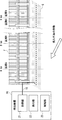
- the acquisition unit 21 sequentially acquires the environmental information included in the optical signal from the optical signal received from the optical fiber 10. Then, the acquisition unit 21 accumulates a plurality of environmental information acquired during the first period (Day 1 in the example of FIG. 2), and generates a first environmental pattern based on the accumulated plurality of environmental information. For example, the acquisition unit 21 generates a first environmental pattern by accumulating a plurality of environmental information acquired in the first period.
- the acquisition unit 21 accumulates a plurality of environmental information acquired during the second period (Day 2 in the example of FIG. 2), and generates a second environmental pattern based on the accumulated plurality of environmental information. ..
- the acquisition unit 21 generates a second environmental pattern by accumulating a plurality of environmental information acquired in the second period.
- the first period and the second period are set to the same time. Also, this time is a fixed length.
- the first period and the second period are set to one day, but the present invention is not limited to this, and may be, for example, one week, half a day (12 hours), one hour, or the like.
- the detection unit 22 detects an event around the optical fiber 10 based on the first environmental pattern in the first period and the second environmental pattern in the second period. More specifically, the detection unit 22 compares the first environmental pattern and the second environmental pattern, and based on the displacement between the first environmental pattern and the second environmental pattern, around the optical fiber 10. Detect the event. For example, when the displacement between the first environmental pattern and the second environmental pattern satisfies a predetermined condition, the detection unit 22 detects an event corresponding to the condition. For example, the detection unit 22 detects an abnormality when the displacement indicates an increase in vibration.
- FIG. 3 a specific example of the environment pattern generation operation by the acquisition unit 21 and the environment pattern comparison operation by the detection unit 22 will be described.
- environmental information indicating the magnitude [nm] of vibration of the optical fiber 10 is used.
- the acquisition unit 21 acquires three environmental information associated with the reception timings t4, t5, and t6 for receiving the optical signal from the optical fiber 10. Then, the acquisition unit 21 generates a second environmental pattern based on the acquired three environmental information.
- the second environment pattern may be generated by the same generation method as the first environment pattern.
- the detection unit 22 compares the first environmental pattern with the second environmental pattern. As a result of comparison, the displacement between the first environmental pattern and the second environmental pattern shows an increasing tendency of vibration. Therefore, the detection unit 22 detects an abnormality.
- an environmental pattern is generated based on the environmental information associated with the reception timing of receiving the optical signal (backscattered light) from the optical fiber 10, but the present invention is not limited to this.
- the environmental information may be associated with the transmission timing at which the pulsed light is transmitted to the optical fiber 10.
- the environmental information may be three environmental information associated with the transmission timings t1, t2, and t3 of transmitting the pulsed light to the optical fiber 10 in the first period. ..
- the environmental information may be three environmental information associated with the transmission timings t4, t5, and t6 at which the pulsed light is transmitted to the optical fiber 10.
- the acquisition unit 21 acquires three environmental information from each of the three optical signals received at the reception timings t1', t2', and t3'.
- the optical signal corresponding to the pulsed light transmitted at the transmission timing t3 is the optical signal received from the optical fiber 10 at the reception timing t3', but the reception timing t3'is in the second period. It has become. However, even in this case, the acquisition unit 21 acquires the environmental information associated with the transmission timing t3 as the environmental information in the first period.
- the acquisition unit 21 acquires environmental information from the optical signal received from the optical fiber 10 (step S11). Then, the acquisition unit 21 generates the first environmental pattern based on the environmental information acquired in the first period (step S12). Similarly, the acquisition unit 21 generates a second environmental pattern based on the environmental information acquired in the second period (step S13).
- the detection unit 22 detects an event around the optical fiber 10 based on the first environmental pattern in the first period and the second environmental pattern in the second period (step S14). .. Note that this detection may be performed, for example, based on the displacement between the first environmental pattern and the second environmental pattern, as described above.
- the acquisition unit 21 generates the first environmental pattern based on the environmental information acquired from the optical signal in the first period, and also generates the light in the second period.
- a second environmental pattern is generated based on the environmental information acquired from the signal.
- the detection unit 22 detects an event around the optical fiber 10 based on the first environmental pattern in the first period and the second environmental pattern in the second period. In this way, since the events around the optical fiber 10 are detected based on the environmental patterns in the two different periods, it is possible to accurately detect even the events in which the situation gradually changes over a long period of time. .. Therefore, by optical fiber sensing, events around the optical fiber 10 can be detected more accurately.
- the acquisition unit 21 may additionally generate a third environmental pattern in the third period (see FIG. 2) and a fourth environmental pattern in the fourth period. That is, the acquisition unit 21 may generate three or more environmental patterns in three or more periods. When generating three or more environmental patterns, a plurality of displacements are required (for example, when generating three environmental patterns, three displacements are required). Therefore, the detection unit 22 may detect an event (abnormality) around the optical fiber 10 when a plurality of displacements satisfy predetermined conditions.
- the acquisition unit 21 has a first environmental pattern in the first period, a second environmental pattern in the second period, a third environmental pattern in the third period, and a fourth environmental pattern in the fourth period. And assume that a fifth environmental pattern in the fifth period is generated.
- each period has passed in the order of the first period, the second period, the third period, the fourth period, and the fifth period.
- the first displacement between the first and second environmental patterns, the second displacement between the second and third environmental patterns, the third environmental pattern and the fourth A third displacement between the environmental patterns and a fourth displacement between the fourth and fifth environmental patterns are sought.
- the detection unit 22 detects an event (abnormality) around the optical fiber 10 when all of the obtained displacements satisfy a predetermined condition (for example, indicating an increase in vibration). Further, the detection unit 22 may detect an event (abnormality) around the optical fiber 10 when a predetermined number or more of the determined displacements satisfy a predetermined condition. For example, the detection unit 22 detects an event (abnormality) around the optical fiber 10 when three or more of the four displacements satisfy a predetermined condition.
- the predetermined number may be obtained by an arbitrary ratio with respect to the number of displacements.
- the first to fourth displacements are required, but the required displacements are not limited to this.
- the fifth displacement between the first environmental pattern and the third environmental pattern may be determined.
- the detection device 20 may further include a notification unit 23.
- the notification unit 23 notifies that the detection unit 22 has detected an event.
- Examples of the notification method of the notification unit 23 include a method of displaying a GUI (Graphical User Interface) screen on a display unit 30 such as a display or a monitor.
- the display unit 30 may be provided in the same facility as the facility in which the detection device 20 is provided, or may be provided in another facility.
- the notification method of the notification unit 23 may be a method of outputting a message by voice from a speaker (not shown).
- the detection system according to the second embodiment has the same basic configuration as the first embodiment described above, but operates differently. As shown in FIG. 8, in the detection system according to the second embodiment, the section in which the optical fiber 10 is laid is divided into a plurality of sections (in the example of FIG. 8, four sections A to D). Events around the optical fiber 10 are detected for each section.
- the acquisition unit 21 holds in advance a correspondence table in which the distance from the detection device 20 in the optical fiber 10 and each section are associated with each other. Further, the acquisition unit 21 generates the optical signal based on, for example, the time difference between transmitting the pulsed light to the optical fiber 10 and receiving the optical signal (backward scattered light), the intensity of the received optical signal, and the like. It is possible to specify at which position on the optical fiber 10 (distance from the detection device 20 in the optical fiber 10) the occurrence occurred.
- the acquisition unit 21 determines which section of the optical fiber 10 the environmental information contained in the optical signal is based on the position on the optical fiber 10 where the optical signal is generated and the corresponding table shown in FIG. It is possible to identify whether it is a thing.
- the acquisition unit 21 sequentially acquires the environmental information included in the optical signal of the section for each section from the optical signals received from the plurality of sections of the optical fiber 10. Then, the acquisition unit 21 accumulates a plurality of environmental information acquired in the first period for each section, and generates a first environmental pattern based on the accumulated plurality of environmental information. Similarly, the acquisition unit 21 accumulates a plurality of environmental information acquired in the second period for each section, and generates a second environmental pattern based on the accumulated plurality of environmental information. As in the first embodiment described above, the first period and the second period are set to the same time. Also, this time is a fixed length.
- the detection unit 22 detects an event around the optical fiber 10 based on the first environmental pattern in the first period and the second environmental pattern in the second period for each section. More specifically, the detection unit 22 compares the first environmental pattern and the second environmental pattern for each section, and based on the displacement between the first environmental pattern and the second environmental pattern, the optical fiber. Detect events around 10. For example, when the displacement between the first environmental pattern and the second environmental pattern satisfies a predetermined condition in a certain section, the detection unit 22 detects an event corresponding to the condition.
- the acquisition unit 21 acquires environmental information for each section from optical signals received from a plurality of sections of the optical fiber 10 (step S21). Then, the acquisition unit 21 generates a first environmental pattern for each section based on the environmental information acquired in the first period (step S22). Similarly, the acquisition unit 21 generates a second environmental pattern for each section based on the environmental information acquired in the second period (step S23).
- the detection unit 22 detects an event around the optical fiber 10 based on the first environmental pattern in the first period and the second environmental pattern in the second period for each section. (Step S24). Note that this detection may be performed, for example, based on the displacement between the first environmental pattern and the second environmental pattern for each section, as described above.
- the acquisition unit 21 generates the first environmental pattern in the first period and the second environmental pattern in the second period for each section. ..
- the detection unit 22 detects an event around the optical fiber 10 based on the first environmental pattern in the first period and the second environmental pattern in the second period for each section. Therefore, it is possible to more accurately detect the events around the optical fiber 10 for each section.
- Some sections may be monitored in a shorter period of time compared to other sections. For example, if it is desired to detect an event in section C early, the acquisition unit 21 may generate an environment pattern every 12 hours only in section C while generating an environment pattern every day in sections A, B, and D. good. As a result, the event can be detected in the section C earlier than in the other sections.
- the detection unit 22 determines the displacement between the first environment pattern and the second environment pattern in two or more sections. Suppose that the conditions are met. In this case, the section with the largest displacement is considered to be the section near the position where the event is occurring. Therefore, the detection unit 22 may specify the section having the largest displacement among the two or more sections in which the displacement satisfies a predetermined condition. This makes it possible to identify the section near the position where the event is occurring.
- the detection unit 22 may detect an event by comparing the displacements of the first environmental pattern and the second environmental pattern obtained for each section with each other between the sections. For example, when the event is an intrusion act, it is possible to specify the moving direction of the position where the intrusion act occurs by comparing the displacements obtained for each section with each other (details will be described later).
- the acquisition unit 21 may generate three or more environmental patterns in three or more periods. Further, when generating three or more environmental patterns, a plurality of displacements are required. Therefore, when the plurality of displacements satisfy a predetermined condition, an event around the optical fiber 10 ( Abnormality) may be detected.
- the detection device 20 may further include a notification unit 23.
- the notification destination of the notification unit 23 may be different for each section.
- the notification destination of the event occurring in the sections A and B is the display unit 30-1 provided in the facility # 1
- the notification destination of the event occurring in the sections C and D is the facility. It is a display unit 30-2 provided in # 2.
- the notification method of the notification unit 23 is a method of displaying the GUI screen on the display units 30-1 and 30-2.
- the notification method of the notification unit 23 may be a method of outputting a message by voice from a speaker (not shown).
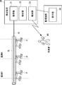
- the detection system according to the third embodiment detects an intrusion act such as tunnel excavation or movement in a tunnel as an event around the optical fiber 10.
- the basic configuration and operation of the detection system according to the third embodiment are the same as those of the first and second embodiments described above.
- the optical fiber 10 is laid in the underground G along the border, the boundary between the site and the outside, and the like.
- the optical fiber 10 may be laid inside the pipe provided in the underground G, or the optical fiber 10 may be laid directly in the underground G. good.
- the method of laying the optical fiber 10 is not limited to this.
- the optical fiber 10 may be attached to the fence F, the wall, or the like.
- the detection unit 22 detects an intrusion act when the displacement between the first environmental pattern and the second environmental pattern shows an increasing tendency of vibration.
- the notification unit 23 When the detection unit 22 detects an intrusion, the notification unit 23 notifies the monitoring facility of the occurrence of the intrusion and the section where the intrusion has occurred. Further, the notification unit 23 may specify the observer in the section where the intrusion act occurs, and notify the specified observer of the occurrence of the intrusion act and the section where the intrusion act occurs. In the example of FIG. 12, it is assumed that the notification method of the notification unit 23 is a method of displaying the GUI screen on the display unit 30 in the monitoring facility or the terminal 40 owned by the observer. However, the notification method of the notification unit 23 may be a method of outputting a message by voice from a speaker (not shown).
- the acquisition unit 21 receives an optical signal from the optical fiber 10 in the first period. Is generated, the first environment pattern is generated based on the three environment information associated with the reception timings t1, t2, and t3, respectively. Similarly, in the second period, the acquisition unit 21 also receives the optical signal from the optical fiber 10 based on the three environmental information associated with the reception timings t4, t5, and t6, respectively, in the second environment. Generate a pattern. In the case of tunnel excavation, environmental information is considered to change gradually over a long period of time. Therefore, the first period and the second period are long periods (for example, one day, half a day, etc.).
- the detection unit 22 compares the first environmental pattern with the second environmental pattern. As a result of comparison, the displacement between the first environmental pattern and the second environmental pattern shows an increasing tendency of vibration. Therefore, the detection unit 22 detects the tunnel excavation.
- the acquisition unit 21 receives light from the optical fiber 10 in the first period.
- the first environmental pattern is generated based on the three environmental information associated with the reception timings t1, t2, and t3 that received the signal.
- the acquisition unit 21 also receives the optical signal from the optical fiber 10 based on the three environmental information associated with the reception timings t4, t5, and t6, respectively, in the second environment. Generate a pattern.
- the environmental information is considered to change in a short period of time. Therefore, the first period and the second period are short periods (for example, 30 minutes, 10 minutes, etc.).
- the minimum values of the three environmental information are used as the first environmental pattern and the second environmental pattern.
- the first environmental pattern is 3 nm
- the second environmental pattern is 6 nm.
- the detection unit 22 compares the first environmental pattern with the second environmental pattern. As a result of comparison, the displacement between the first environmental pattern and the second environmental pattern shows an increasing tendency of vibration. Therefore, the detection unit 22 detects the movement in the tunnel.
- the detection unit 22 utilizes the fact that the position where the intrusion act occurs gradually approaches the optical fiber 10, and the first environment pattern and the second environment pattern Intrusion is detected when the displacement with and shows an increasing tendency of vibration. This makes it possible to detect intrusions by distinguishing vibrations from constant vibration events (construction in the neighborhood, parallel movement of ground guards, etc.) and momentary vibration events (earthquakes, accidents, shootings, etc.). it can.
- the detection unit 22 may compare the displacements of each section to obtain the moving direction of the position where the intrusion act occurs. For example, the displacement in the compartment B is larger than the displacement in the compartment A, and the displacement in the compartment A is larger than the displacement in the compartment B. Suppose the relationships are swapped. In this case, as shown in FIG. 15, the detection unit 22 can detect that the position where the intrusion act occurs is laterally moving from the section B toward the section A.
- the detection system according to the fourth embodiment detects the deterioration of the pipeline as an event around the optical fiber 10.
- the basic configuration and operation of the detection system according to the fourth embodiment are the same as those of the first and second embodiments described above.
- the optical fiber 10 is attached to the pipeline PL.
- a linear optical fiber 10 is passed through the inside of the pipeline PL along the pipeline PL, but the method of attaching the optical fiber 10 is not limited to this.
- the optical fiber 10 may be spiral, or the optical fiber 10 may crawl inside or outside the pipeline PL along the pipeline PL.
- the pipeline PL is supported by three pillars P and laid on the ground, but the laying place of the pipeline PL may be any place such as the ground, the ground, the ceiling, the floor, and the wall.
- the detection unit 22 detects the deterioration of the pipeline PL when the displacement between the first environmental pattern and the second environmental pattern shows an increasing tendency of vibration.
- the detection unit 22 detects the deterioration of the pipeline PL when the displacement between the first environmental pattern and the second environmental pattern shows an increasing tendency of the temperature.
- the notification unit 23 When the detection unit 22 detects the deterioration of the pipeline PL, the notification unit 23 notifies the monitoring facility of the occurrence of the deterioration of the pipeline PL and the position where the deterioration occurs. Further, the notification unit 23 may specify an operator near the position where the deterioration occurs, and notify the specified operator of the occurrence of the deterioration of the pipeline PL and the position where the deterioration occurs. In the example of FIG. 16, it is assumed that the notification method of the notification unit 23 is a method of displaying the GUI screen on the display unit 30 in the monitoring facility or the terminal 40 owned by the operator. However, the notification method of the notification unit 23 may be a method of outputting a message by voice from a speaker (not shown).
- the acquisition unit 21 is the first based on three environmental information associated with the reception timings t1, t2, and t3 of receiving the optical signal from the optical fiber 10 in the first period. Generate the environment pattern of 1. Similarly, in the second period, the acquisition unit 21 also receives the optical signal from the optical fiber 10 based on the three environmental information associated with the reception timings t4, t5, and t6, respectively, in the second environment. Generate a pattern. In the case of deterioration of the pipeline PL, it is considered that the environmental information gradually changes over a long period of time. Therefore, the first period and the second period are long periods (for example, one week, one day, etc.).
- the detection unit 22 compares the first environmental pattern with the second environmental pattern. As a result of comparison, the displacement between the first environmental pattern and the second environmental pattern shows an increasing tendency of vibration. Therefore, the detection unit 22 detects the deterioration of the pipeline PL.
- the acquisition unit 21 in the first period, is the first based on three environmental information associated with the reception timings t1, t2, and t3 of receiving the optical signal from the optical fiber 10. Generate the environment pattern of 1.
- the acquisition unit 21 also receives the optical signal from the optical fiber 10 based on the three environmental information associated with the reception timings t4, t5, and t6, respectively, in the second environment. Generate a pattern.
- the first period and the second period are long periods (for example, one week, one day, etc.) as in the case of Specific Example 1 of (D1) described above.
- the detection unit 22 compares the first environmental pattern with the second environmental pattern. As a result of comparison, the displacement between the first environmental pattern and the second environmental pattern shows an increasing tendency of temperature. Therefore, the detection unit 22 detects the deterioration of the pipeline PL.
- the detection unit 22 uses the fact that the vibration increases as the pipeline PL deteriorates to obtain the first environmental pattern and the second environmental pattern. Deterioration of the pipeline PL is detected when the displacement of is showing an increasing tendency of vibration. As a result, deterioration of the pipeline PL can be detected by distinguishing it from an event in which vibration is constant (operation of peripheral devices, etc.) or an event in which vibration occurs instantaneously (collision with the pipeline PL, etc.).
- the detection unit 22 utilizes the fact that the temperature rises as the pipeline PL deteriorates, and when the displacement between the first environmental pattern and the second environmental pattern shows an increasing tendency of the temperature. , Detects deterioration of pipeline PL. As a result, deterioration of the pipeline PL can be detected by distinguishing it from an event in which the temperature changes temporarily (change in outside air temperature).
- the optical fiber 10 may be attached to a structure such as a bridge, a building, or a road to detect deterioration of these structures.
- the method of attaching the optical fiber 10 to these structures may be the same as the method of attaching to the pipeline PL.
- the detection system according to the fifth embodiment detects a sediment-related disaster as an event around the optical fiber 10.
- the basic configuration and operation of the detection system according to the fifth embodiment are the same as those of the first and second embodiments described above.
- the optical fiber 10 is laid on the slope of a mountain. Further, the region in which the optical fiber 10 is laid is divided into a plurality of regions (in the example of FIG. 19, four regions A to D), and the vertical positional relationship of the plurality of regions is determined in advance. In the example of FIG. 19, the vertical positional relationship of the area A at the top and the area B at the bottom is defined, and the vertical positional relationship of the area D at the top and the area C at the bottom is defined.
- the acquisition unit 21 holds in advance a correspondence table in which the distance from the detection device 20 in the optical fiber 10 and each region are associated with each other. Further, as described above, the acquisition unit 21 is based on the time difference between the transmission of the pulsed light and the reception of the optical signal (backward scattered light), the intensity of the received optical signal (backward scattered light), and the like. It is possible to specify at which position on the optical fiber 10 the optical signal is generated (distance from the detection device 20 in the optical fiber 10).
- the acquisition unit 21 can obtain the environmental information contained in the optical signal in any region on the optical fiber 10 based on the position on the optical fiber 10 where the optical signal is generated and the corresponding table shown in FIG. It is possible to identify whether it is a thing.
- the detection unit 22 uses the pressure applied to the optical fiber 10 by the displacement between the first environmental pattern and the second environmental pattern in the upper region of the two regions in the vertical positional relationship. In the lower region, sediment disasters are detected when the displacement between the first environmental pattern and the second environmental pattern shows an increasing tendency of the pressure applied to the optical fiber 10.
- the notification unit 23 may cause a sediment-related disaster or flood the police station that has jurisdiction over the location of the sediment-related disaster or the residents living near the location where the sediment-related disaster occurs. Notify that there is.
- the notification method of the notification unit 23 is a method of displaying the GUI screen on the display unit 30 in the police station or the terminal 40 owned by the residents in the vicinity.
- the notification method of the notification unit 23 may be a method of outputting a message by voice from a speaker (not shown).
- FIG. 21 a specific example of the environment pattern generation operation by the acquisition unit 21 and the environment pattern comparison operation by the detection unit 22 when detecting a sediment-related disaster will be described.
- the environmental information indicating the pressure [nPa] applied to the optical fiber 10 is used, and the environmental information of the two regions A and B in the vertical positional relationship is shown.
- the acquisition unit 21 is used for each of the areas A and B in the first period.
- the first environmental pattern is generated based on the three environmental information associated with the reception timings t1, t2, and t3 that received the optical signal from the optical fiber 10.
- the acquisition unit 21 provides the three environmental information associated with the reception timings t4, t5, and t6 for receiving the optical signal from the optical fiber 10 for each of the regions A and B. Based on this, a second environmental pattern is generated.
- the first period and the second period are long periods (for example, one week, one day, etc.).
- the detection unit 22 compares the first environment pattern and the second environment pattern for each of the areas A and B. As a result of comparison, in the upper region A, the displacement between the first environmental pattern and the second environmental pattern shows a decreasing tendency of pressure. On the other hand, in the lower region B, the displacement between the first environmental pattern and the second environmental pattern shows an increasing tendency of pressure. Therefore, the detection unit 22 detects a sediment-related disaster.
- a sediment-related disaster was detected based on the environmental patterns of the two regions A and B in the vertical positional relationship, but the environmental patterns of the two regions D and C in the vertical positional relationship were detected. Sediment-related disasters may be detected based on.
- the detection unit 22 utilizes the fact that the amount of sediment gradually moves downward when a landslide or other sediment-related disaster occurs, and in the upper region, the detection unit 22 is the first.
- the displacement between the first environmental pattern and the second environmental pattern shows a decreasing tendency of the pressure applied to the optical fiber 10, and in the lower region, the displacement between the first environmental pattern and the second environmental pattern is on the optical fiber 10.
- a landslide disaster is detected when the applied pressure tends to increase. This makes it possible to detect sediment-related disasters by distinguishing them from events in which pressure is displaced within only one area (tunnel construction, building construction, etc.) and events in which pressure is instantaneously generated (earthquakes, etc.). ..
- the detection system according to the sixth embodiment detects the possibility of river flooding as an event around the optical fiber 10.
- the basic configuration and operation of the detection system according to the sixth embodiment are the same as those of the first and second embodiments described above.
- the optical fiber 10 is laid on the side surface of the river Rv along the longitudinal direction of the river Rv.
- the method of laying the optical fiber 10 is not limited to this, and for example, it may be laid on the bottom surface of the river Rv along the longitudinal direction of the river Rv.
- the detection unit 22 may inundate the river Rv when the displacement between the first environmental pattern and the second environmental pattern shows an increasing tendency of the pressure (water pressure) applied to the optical fiber 10. Is detected.
- the notification unit 23 may cause flooding to the police station that has jurisdiction over the location where there is a risk of flooding and the surrounding residents living near that location. Is notified.
- the notification method of the notification unit 23 is a method of displaying the GUI screen on the display unit 30 in the police station or the terminal 40 owned by the residents in the vicinity.
- the notification method of the notification unit 23 may be a method of outputting a message by voice from a speaker (not shown).
- FIG. 23 a specific example of the environment pattern generation operation by the acquisition unit 21 and the environment pattern comparison operation by the detection unit 22 when detecting the possibility of flooding of the river Rv will be described.
- environmental information indicating the pressure [nPa] applied to the optical fiber 10 is used.
- the acquisition unit 21 uses an optical fiber in the first period.
- the first environmental pattern is generated based on the three environmental information associated with the reception timings t1, t2, and t3 that received the optical signal from 10.
- the acquisition unit 21 also receives the optical signal from the optical fiber 10 based on the three environmental information associated with the reception timings t4, t5, and t6, respectively, in the second environment. Generate a pattern.
- environmental information is considered to change in a short period of time. Therefore, the first period and the second period are short periods (for example, 1 hour, 30 minutes, etc.).
- the detection unit 22 compares the first environmental pattern with the second environmental pattern. As a result of comparison, the displacement between the first environmental pattern and the second environmental pattern shows an increasing tendency of pressure. Therefore, the detection unit 22 detects the possibility of flooding of the river Rv.
- the detection unit 22 utilizes the fact that the amount of water in the river Rv increases when the risk of flooding of the river Rv increases, and the first environmental pattern and the second environmental pattern 22 When the displacement with the environmental pattern shows an increasing tendency of the pressure (water pressure) applied to the optical fiber 10, the possibility of flooding of the river Rv is detected. As a result, it is possible to detect the possibility of flooding of the river Rv by distinguishing it from an event in which the water pressure rises momentarily (passage of a ship, etc.).
- the optical fiber 10 may be laid at the floodgate of the dam, and an increase or decrease in the amount of water in the dam may be detected based on an increase / decrease tendency of the water pressure according to the flow rate of water passing through the floodgate.
- the detection system according to the seventh embodiment detects road congestion as an event around the optical fiber 10.
- the basic configuration and operation of the detection system according to the seventh embodiment are the same as those of the first and second embodiments described above.
- the optical fiber 10 is laid along the road Rd.
- the optical fiber 10 may be laid in a straight line or in a wavy shape along the road Rd. Further, the optical fiber 10 may be laid under the road Rd or may be laid beside the road Rd.
- the detection unit 22 detects congestion when the displacement between the first environmental pattern and the second environmental pattern shows an increasing tendency of pressure.
- the detection unit 22 detects congestion when the displacement between the first environmental pattern and the second environmental pattern shows a decreasing tendency of vibration.
- the notification unit 23 When the detection unit 22 detects a traffic jam, the notification unit 23 notifies the management facility of the road Rd of the occurrence of the traffic jam and the position where the traffic jam occurs.
- the notification method of the notification unit 23 is a method of displaying the GUI screen on the display unit 30 in the monitoring facility.
- the notification method of the notification unit 23 may be a method of outputting a message by voice from a speaker (not shown).
- the acquisition unit 21 is the first based on three environmental information associated with the reception timings t1, t2, and t3 of receiving the optical signal from the optical fiber 10. Generate the environment pattern of 1.
- the acquisition unit 21 also receives the optical signal from the optical fiber 10 based on the three environmental information associated with the reception timings t4, t5, and t6, respectively, in the second environment. Generate a pattern.
- the environmental information is considered to change in a short period of time. Therefore, the first period and the second period are short periods (for example, 1 hour, 30 minutes, etc.).
- the detection unit 22 compares the first environmental pattern with the second environmental pattern. As a result of comparison, the displacement between the first environmental pattern and the second environmental pattern shows an increasing tendency of pressure. Therefore, the detection unit 22 detects the traffic jam.
- the acquisition unit 21 in the first period, is the first based on three environmental information associated with the reception timings t1, t2, and t3 of receiving the optical signal from the optical fiber 10. Generate the environment pattern of 1.
- the acquisition unit 21 also receives the optical signal from the optical fiber 10 based on the three environmental information associated with the reception timings t4, t5, and t6, respectively, in the second environment. Generate a pattern.
- the first period and the second period are short periods (for example, 1 hour, 30 minutes, etc.) as in the case of Specific Example 1 of (G1) described above.
- the detection unit 22 compares the first environmental pattern with the second environmental pattern. As a result of comparison, the displacement between the first environmental pattern and the second environmental pattern shows a decreasing tendency of vibration. Therefore, the detection unit 22 detects the traffic jam.
- the detection unit 22 may detect traffic congestion by combining (G1) and (G2) described above. That is, the detection unit 22 may detect congestion when the displacement between the first environmental pattern and the second environmental pattern shows both an increasing tendency of pressure and a decreasing tendency of vibration.
- the detection unit 22 uses the fact that the density of the vehicle increases when the road Rd is congested to obtain the first environmental pattern and the second environmental pattern. Congestion is detected when the displacement of is showing an increasing tendency of pressure. This makes it possible to detect traffic congestion by distinguishing it from an event in which pressure is constant (road construction, etc.) or an event in which pressure is instantaneously generated (earthquake, passage of a heavy vehicle, etc.).
- the detection unit 22 utilizes the fact that the vehicle decelerates when a traffic jam occurs on the road Rd, and the traffic jam occurs when the displacement between the first environmental pattern and the second environmental pattern shows a decreasing tendency of vibration. Is detected. This makes it possible to detect traffic congestion by distinguishing it from an event in which vibration is constant (road construction, etc.) or an event in which vibration occurs instantaneously (earthquake, passage of a heavy vehicle, etc.).
- the detection unit 22 determines that the second environmental pattern is larger than the first environmental pattern regardless of the magnitude of the displacement between the first environmental pattern and the second environmental pattern. It was judged that it would show an increasing tendency, but it is not limited to this. For example, the detection unit 22 does not determine that when the displacement between the first environment pattern and the second environment pattern is equal to or less than the threshold value, it shows an increasing tendency, and when the displacement exceeds the threshold value, it shows an increasing tendency. You may judge that. The same applies when it is judged that a decreasing tendency is shown.
- the displacement between the first environmental pattern and the second environmental pattern shows a specific tendency (decreasing tendency or increasing tendency)
- a specific tendency decreasing tendency or increasing tendency
- the detection unit 22 may not detect the event. In this case, the acquisition unit 21 may repeatedly acquire the environmental information.
- the detection unit 22 shows a specific tendency in the displacement by one comparison between the environmental patterns (the first environmental pattern and the second environmental pattern), it is an event.
- the detection unit 22 performs comparisons between environmental patterns a plurality of times, and when a specific tendency is continuously shown more than the reference number of times, or when a specific tendency is shown more than the reference number of times, an event is detected. It may be detected.
- the detection unit 22 is not limited to comparing the environmental patterns of continuous periods (for example, the first period and the second period of FIG. 27) with each other, and the detection unit 22 is not limited to comparing the environmental patterns of continuous periods (for example, the first period of FIG. 27).
- the environmental patterns of the period and the third period may be compared with each other.
- the detection device 20 is provided with a plurality of components (acquisition unit 21, detection unit 22, and notification unit 23), but is not limited thereto.
- the components provided in the detection device 20 are not limited to being provided in one device, and may be distributed in a plurality of devices.
- the computer 50 includes a processor 501, a memory 502, a storage 503, an input / output interface (input / output I / F) 504, a communication interface (communication I / F) 505, and the like.
- the processor 501, the memory 502, the storage 503, the input / output interface 504, and the communication interface 505 are connected by a data transmission line for transmitting and receiving data to and from each other.
- the processor 501 is, for example, an arithmetic processing unit such as a CPU (Central Processing Unit) or a GPU (Graphics Processing Unit).
- the memory 502 is, for example, a memory such as a RAM (Random Access Memory) or a ROM (Read Only Memory).
- the storage 503 is, for example, a storage device such as an HDD (Hard Disk Drive), an SSD (Solid State Drive), or a memory card. Further, the storage 503 may be a memory such as a RAM or a ROM.
- the storage 503 stores a program that realizes the functions of the components (acquisition unit 21, detection unit 22, and notification unit 23) included in the detection device 20. By executing each of these programs, the processor 501 realizes the functions of the components included in the detection device 20. Here, when executing each of the above programs, the processor 501 may read these programs on the memory 502 and then execute the programs, or may execute the programs without reading them on the memory 502. The memory 502 and the storage 503 also play a role of storing information and data held by the components included in the detection device 20.
- Non-temporary computer-readable media include various types of tangible storage media.
- Examples of non-temporary computer-readable media include magnetic recording media (eg, flexible disks, magnetic tapes, hard disk drives), opto-magnetic recording media (eg, opto-magnetic discs), CD-ROMs (Compact Disc-ROMs), CDs. -R (CD-Recordable), CD-R / W (CD-ReWritable), semiconductor memory (for example, mask ROM, PROM (Programmable ROM), EPROM (Erasable PROM), flash ROM, RAM.
- the program also includes.
- the computer-readable medium can supply the program to the computer via a wired communication path such as an electric wire and an optical fiber, or a wireless communication path.
- the input / output interface 504 is connected to the display device 5041, the input device 5042, the sound output device 5043, and the like.
- the display device 5041 is a device that displays a screen corresponding to drawing data processed by the processor 501, such as an LCD (Liquid Crystal Display), a CRT (Cathode Ray Tube) display, and a monitor.
- the input device 5042 is a device that receives an operator's operation input, and is, for example, a keyboard, a mouse, a touch sensor, and the like.
- the display device 5041 and the input device 5042 may be integrated and realized as a touch panel.
- the sound output device 5043 is a device such as a speaker that acoustically outputs sound corresponding to acoustic data processed by the processor 501.
- the communication interface 505 sends and receives data to and from an external device.
- the communication interface 505 communicates with an external device via a wired communication path or a wireless communication path.
- (Appendix 1) Optical fiber that detects environmental information and An acquisition unit that acquires the environmental information included in the optical signal received from the optical fiber, and an acquisition unit.
- the optical fiber is based on a first environmental pattern based on environmental information acquired from an optical signal corresponding to a first period and a second environmental pattern based on environmental information acquired from an optical signal corresponding to a second period.
- a detector that detects events around the A detection system.
- (Appendix 2) The acquisition unit The first environmental pattern is generated by integrating the environmental information acquired from the optical signal corresponding to the first period.
- the second environmental pattern is generated by integrating the environmental information acquired from the optical signal corresponding to the second period.
- the detection system according to Appendix 1. (Appendix 3) The detection unit An event around the optical fiber is detected based on the displacement between the first environmental pattern and the second environmental pattern.
- the detection system according to Appendix 1 or 2. (Appendix 4) The acquisition unit The environmental information is acquired for each section from the optical signals received from the plurality of sections of the optical fiber. The first environmental pattern and the second environmental pattern are generated for each of the sections. The detection unit For each section, an event around the optical fiber is detected based on the first environmental pattern and the second environmental pattern.
- the detection system according to any one of Appendix 1 to 3. (Appendix 5) The detection unit For each section, the displacement between the first environmental pattern and the second environmental pattern is obtained. For each section, an event around the optical fiber is detected based on the displacement.
- the detection system according to Appendix 4.
- the acquisition unit The environmental information is acquired for each section from the optical signals received from the plurality of sections of the optical fiber.
- the first environmental pattern and the second environmental pattern are generated for each of the sections.
- the detection unit For each section, the displacement between the first environmental pattern and the second environmental pattern is obtained. Detecting events around the optical fiber based on the difference in displacement in different sections.
- the detection system according to any one of Appendix 1 to 3.
- the acquisition unit Acquires the environmental information indicating at least one of the temperature of the optical fiber, the vibration of the optical fiber, and the pressure applied to the optical fiber.
- the detection system according to any one of Appendix 1 to 6.
- a notification unit for notifying that the detection unit has detected an event is further provided.
- the detection system according to any one of Appendix 1 to 7.
- the detection unit Based on the first environmental pattern based on the environmental information acquired from the optical signal received in the first period and the second environmental pattern based on the environmental information acquired from the optical signal received in the second period. , Detecting events around the optical fiber, The detection system according to any one of Appendix 1 to 5.
- the detection unit The first environmental pattern based on the environmental information acquired from the backward scattered light generated in the optical fiber by the light emitted in the first period and the light emitted in the second period are generated in the optical fiber.
- the event around the optical fiber is detected based on the second environmental pattern based on the environmental information acquired from the backward scattered light.
- the detection system according to any one of Appendix 1 to 5.
- Appendix 11 It is a detection method by the detection system.
- the optical fiber is based on a first environmental pattern based on environmental information acquired from an optical signal corresponding to a first period and a second environmental pattern based on environmental information acquired from an optical signal corresponding to a second period.
- Appendix 12 In the acquisition step,
- the first environmental pattern is generated by integrating the environmental information acquired from the optical signal corresponding to the first period.
- the second environmental pattern is generated by integrating the environmental information acquired from the optical signal corresponding to the second period.
- the detection method according to Appendix 11. (Appendix 13) In the detection step, An event around the optical fiber is detected based on the displacement between the first environmental pattern and the second environmental pattern.
- the detection method according to Appendix 11 or 12. (Appendix 14) In the acquisition step, The environmental information is acquired for each section from the optical signals received from the plurality of sections of the optical fiber. The first environmental pattern and the second environmental pattern are generated for each of the sections. In the detection step, For each section, an event around the optical fiber is detected based on the first environmental pattern and the second environmental pattern.
- Appendix 17 In the acquisition step, Acquires the environmental information indicating at least one of the temperature of the optical fiber, the vibration of the optical fiber, and the pressure applied to the optical fiber.
- Appendix 18 A notification step for notifying that an event has been detected in the detection step is further included.
- Appendix 19 In the detection step, Based on the first environmental pattern based on the environmental information acquired from the optical signal received in the first period and the second environmental pattern based on the environmental information acquired from the optical signal received in the second period. , Detecting events around the optical fiber, The detection method according to any one of Appendix 11 to 15.
- the first environmental pattern based on the environmental information acquired from the backward scattered light generated in the optical fiber by the light emitted in the first period and the light emitted in the second period are generated in the optical fiber.
- the event around the optical fiber is detected based on the second environmental pattern based on the environmental information acquired from the backward scattered light.
- the detection method according to any one of Appendix 11 to 15.
- the optical fiber is based on a first environmental pattern based on environmental information acquired from an optical signal corresponding to a first period and a second environmental pattern based on environmental information acquired from an optical signal corresponding to a second period.
- a detector that detects events around the A detection device.
- Optical fiber 20 Detection device 21 Acquisition unit 22 Detection unit 23 Notification unit 30, 30-1, 30-2 Display unit 40 Terminal 50 Computer 501 Processor 502 Memory 503 Storage 504 Input / output interface 5041 Display device 5042 Input device 5043 Sound output device 505 Communication Interface F Fence G Underground PL Pipeline Rv River Rd Road
Landscapes
- Physics & Mathematics (AREA)
- General Physics & Mathematics (AREA)
- Optical Transform (AREA)
- Testing Or Calibration Of Command Recording Devices (AREA)
Priority Applications (3)
| Application Number | Priority Date | Filing Date | Title |
|---|---|---|---|
| PCT/JP2019/038524 WO2021064797A1 (ja) | 2019-09-30 | 2019-09-30 | 検出システム、検出方法、及び検出装置 |
| US17/763,363 US12222248B2 (en) | 2019-09-30 | 2019-09-30 | Detection system, detection method, and detection device |
| JP2021550756A JP7371693B2 (ja) | 2019-09-30 | 2019-09-30 | 検出システム、検出方法、及び検出装置 |
Applications Claiming Priority (1)
| Application Number | Priority Date | Filing Date | Title |
|---|---|---|---|
| PCT/JP2019/038524 WO2021064797A1 (ja) | 2019-09-30 | 2019-09-30 | 検出システム、検出方法、及び検出装置 |
Publications (1)
| Publication Number | Publication Date |
|---|---|
| WO2021064797A1 true WO2021064797A1 (ja) | 2021-04-08 |
Family
ID=75337773
Family Applications (1)
| Application Number | Title | Priority Date | Filing Date |
|---|---|---|---|
| PCT/JP2019/038524 Ceased WO2021064797A1 (ja) | 2019-09-30 | 2019-09-30 | 検出システム、検出方法、及び検出装置 |
Country Status (3)
| Country | Link |
|---|---|
| US (1) | US12222248B2 (https=) |
| JP (1) | JP7371693B2 (https=) |
| WO (1) | WO2021064797A1 (https=) |
Citations (6)
| Publication number | Priority date | Publication date | Assignee | Title |
|---|---|---|---|---|
| JP2001066117A (ja) * | 1999-08-30 | 2001-03-16 | Railway Technical Res Inst | トンネルひび割れおよび補強材剥離検知方法及び装置 |
| JP2002140774A (ja) * | 2000-11-01 | 2002-05-17 | Sumitomo Forestry Co Ltd | 住宅管理方法 |
| JP2005257570A (ja) * | 2004-03-12 | 2005-09-22 | Kajima Corp | 光ファイバによる構造物の診断方法及びシステム |
| US20100290734A1 (en) * | 2009-05-14 | 2010-11-18 | Celight, Inc. | Optical sensor for detecting and localizing events |
| JP2017220981A (ja) * | 2016-06-03 | 2017-12-14 | 東芝プラントシステム株式会社 | 電路温度監視システム、電路温度監視装置および電路温度監視方法 |
| JP2018190428A (ja) * | 2015-02-17 | 2018-11-29 | 富士通株式会社 | 判定装置、判定方法および判定プログラム |
Family Cites Families (9)
| Publication number | Priority date | Publication date | Assignee | Title |
|---|---|---|---|---|
| JP3312575B2 (ja) * | 1997-03-25 | 2002-08-12 | 日立電線株式会社 | 地形変位検知用光ファイバセンサの布設方法及び地形変位検知装置 |
| BRPI0414359A (pt) * | 2000-06-16 | 2006-11-14 | Bodymedia Inc | sistema para a monitoração e gerenciamento do peso corpóreo e demais condições psicológicas que abrangem um planejamento interativo e personalizado, intervenção e capacidade de formular relatórios |
| JP4418376B2 (ja) | 2005-01-26 | 2010-02-17 | 株式会社クレヴァシステムズ | 侵入検知センサー |
| WO2007008431A2 (en) * | 2005-07-06 | 2007-01-18 | The Penn State Research Foundation | A networked multiband waveguide intrusion detection and localization sensor |
| JP4665779B2 (ja) | 2006-01-27 | 2011-04-06 | パナソニック電工株式会社 | フェンス振動センサ装置 |
| US20090195401A1 (en) * | 2008-01-31 | 2009-08-06 | Andrew Maroney | Apparatus and method for surveillance system using sensor arrays |
| US9000918B1 (en) * | 2013-03-02 | 2015-04-07 | Kontek Industries, Inc. | Security barriers with automated reconnaissance |
| GB201408130D0 (en) * | 2014-05-08 | 2014-06-25 | Optasense Holdings Ltd | Improvements in fibre optic distributed sensing |
| US9268938B1 (en) * | 2015-05-22 | 2016-02-23 | Power Fingerprinting Inc. | Systems, methods, and apparatuses for intrusion detection and analytics using power characteristics such as side-channel information collection |
-
2019
- 2019-09-30 JP JP2021550756A patent/JP7371693B2/ja active Active
- 2019-09-30 US US17/763,363 patent/US12222248B2/en active Active
- 2019-09-30 WO PCT/JP2019/038524 patent/WO2021064797A1/ja not_active Ceased
Patent Citations (6)
| Publication number | Priority date | Publication date | Assignee | Title |
|---|---|---|---|---|
| JP2001066117A (ja) * | 1999-08-30 | 2001-03-16 | Railway Technical Res Inst | トンネルひび割れおよび補強材剥離検知方法及び装置 |
| JP2002140774A (ja) * | 2000-11-01 | 2002-05-17 | Sumitomo Forestry Co Ltd | 住宅管理方法 |
| JP2005257570A (ja) * | 2004-03-12 | 2005-09-22 | Kajima Corp | 光ファイバによる構造物の診断方法及びシステム |
| US20100290734A1 (en) * | 2009-05-14 | 2010-11-18 | Celight, Inc. | Optical sensor for detecting and localizing events |
| JP2018190428A (ja) * | 2015-02-17 | 2018-11-29 | 富士通株式会社 | 判定装置、判定方法および判定プログラム |
| JP2017220981A (ja) * | 2016-06-03 | 2017-12-14 | 東芝プラントシステム株式会社 | 電路温度監視システム、電路温度監視装置および電路温度監視方法 |
Also Published As
| Publication number | Publication date |
|---|---|
| US20220334006A1 (en) | 2022-10-20 |
| JPWO2021064797A1 (https=) | 2021-04-08 |
| JP7371693B2 (ja) | 2023-10-31 |
| US12222248B2 (en) | 2025-02-11 |
Similar Documents
| Publication | Publication Date | Title |
|---|---|---|
| JP7124876B2 (ja) | 状態特定システム、状態特定装置、状態特定方法、及びプログラム | |
| JP7315014B2 (ja) | 光ファイバセンシングシステム、光ファイバセンシング方法、及び光ファイバセンシング装置 | |
| JP2024014948A (ja) | 道路監視システム、道路監視装置、道路監視方法、及びプログラム | |
| JP7332020B2 (ja) | 光ファイバセンシングシステム、道路監視方法、及び光ファイバセンシング機器 | |
| CN113531399B (zh) | 光纤振动预警方法、装置、计算机设备及存储介质 | |
| JPWO2020116030A1 (ja) | 道路監視システム、道路監視装置、道路監視方法、及びプログラム | |
| JP2019529952A5 (https=) | ||
| JP7235115B2 (ja) | 光ファイバセンシングシステム、光ファイバセンシング機器、及び異常判断方法 | |
| JP7276356B2 (ja) | 光ファイバセンシングシステム、状態検知装置、状態検知方法、及びプログラム | |
| WO2020202654A1 (ja) | 監視システム、監視装置、監視方法、及び非一時的なコンピュータ可読媒体 | |
| JP2009281924A (ja) | 地盤崩壊予測警報システム及び地盤崩壊予測警報方法 | |
| JP7192879B2 (ja) | 線路監視システム、線路監視装置、線路監視方法、及びプログラム | |
| JP7268793B2 (ja) | 光ファイバセンシングシステム、光ファイバセンシング装置及び光ファイバセンシング方法 | |
| JP7338687B2 (ja) | 光ファイバセンシングシステム、光ファイバセンシング機器、及び地中行動監視方法 | |
| JP7533566B2 (ja) | 監視システム、監視装置、及び監視方法 | |
| WO2021064797A1 (ja) | 検出システム、検出方法、及び検出装置 | |
| KR20180061091A (ko) | 센서를 이용한 건축물의 지진감지 알림 시스템 | |
| KR101503878B1 (ko) | 공배관을 통한 층간 소음 통합 관리 시스템 | |
| JPWO2020100509A1 (ja) | 土木構造物監視システム、土木構造物監視装置、土木構造物監視方法、及びプログラム | |
| WO2023053184A1 (ja) | 光ファイバセンシングシステム、光ファイバセンシング機器、及び道路監視方法 | |
| JP2024092385A (ja) | 情報処理装置及び光ファイバセンシングシステム | |
| WO2023053179A1 (ja) | 光ファイバセンシングシステム、光ファイバセンシング機器、及び道路監視方法 | |
| WO2021171593A1 (ja) | 検出システム、検出装置、及び検出方法 | |
| US20240271972A1 (en) | Detection system, detection device, and detection method | |
| US20240361178A1 (en) | Monitoring system, monitoring apparatus, and monitoring method |
Legal Events
| Date | Code | Title | Description |
|---|---|---|---|
| 121 | Ep: the epo has been informed by wipo that ep was designated in this application |
Ref document number: 19947551 Country of ref document: EP Kind code of ref document: A1 |
|
| ENP | Entry into the national phase |
Ref document number: 2021550756 Country of ref document: JP Kind code of ref document: A |
|
| NENP | Non-entry into the national phase |
Ref country code: DE |
|
| 122 | Ep: pct application non-entry in european phase |
Ref document number: 19947551 Country of ref document: EP Kind code of ref document: A1 |