WO2021060543A1 - Corps d'affichage couleur, support d'authentification et procédé de détermination d'authenticité de corps d'affichage couleur - Google Patents
Corps d'affichage couleur, support d'authentification et procédé de détermination d'authenticité de corps d'affichage couleur Download PDFInfo
- Publication number
- WO2021060543A1 WO2021060543A1 PCT/JP2020/036474 JP2020036474W WO2021060543A1 WO 2021060543 A1 WO2021060543 A1 WO 2021060543A1 JP 2020036474 W JP2020036474 W JP 2020036474W WO 2021060543 A1 WO2021060543 A1 WO 2021060543A1
- Authority
- WO
- WIPO (PCT)
- Prior art keywords
- color display
- display body
- refractive index
- image
- wavy
- Prior art date
Links
- 238000000034 method Methods 0.000 title claims description 43
- 230000007704 transition Effects 0.000 claims abstract description 15
- 238000001228 spectrum Methods 0.000 claims description 63
- 239000004033 plastic Substances 0.000 claims description 15
- 229920003023 plastic Polymers 0.000 claims description 15
- 230000015572 biosynthetic process Effects 0.000 claims description 5
- 230000008569 process Effects 0.000 claims description 5
- 239000012528 membrane Substances 0.000 claims 4
- 239000010410 layer Substances 0.000 description 413
- 239000011241 protective layer Substances 0.000 description 46
- 239000000463 material Substances 0.000 description 44
- 101100153168 Arabidopsis thaliana TIC21 gene Proteins 0.000 description 28
- 102100033270 Cyclin-dependent kinase inhibitor 1 Human genes 0.000 description 28
- 101100273813 Homo sapiens CDKN1A gene Proteins 0.000 description 28
- 108700038981 SUMO-1 Proteins 0.000 description 28
- 101100083337 Schizosaccharomyces pombe (strain 972 / ATCC 24843) pic1 gene Proteins 0.000 description 28
- 238000004049 embossing Methods 0.000 description 27
- 101100083338 Saccharomyces cerevisiae (strain ATCC 204508 / S288c) PIC2 gene Proteins 0.000 description 24
- 102100027382 Membrane-bound transcription factor site-2 protease Human genes 0.000 description 22
- 238000012795 verification Methods 0.000 description 18
- 238000000151 deposition Methods 0.000 description 16
- 238000010586 diagram Methods 0.000 description 16
- 229920003002 synthetic resin Polymers 0.000 description 15
- 239000000057 synthetic resin Substances 0.000 description 15
- 230000008021 deposition Effects 0.000 description 13
- 230000008859 change Effects 0.000 description 12
- 238000010894 electron beam technology Methods 0.000 description 9
- 230000003287 optical effect Effects 0.000 description 8
- 229920005989 resin Polymers 0.000 description 8
- 239000011347 resin Substances 0.000 description 8
- 230000000694 effects Effects 0.000 description 7
- 238000004519 manufacturing process Methods 0.000 description 7
- 230000007423 decrease Effects 0.000 description 6
- 229910010413 TiO 2 Inorganic materials 0.000 description 5
- 239000011248 coating agent Substances 0.000 description 5
- 238000000576 coating method Methods 0.000 description 5
- 238000001459 lithography Methods 0.000 description 5
- 230000009471 action Effects 0.000 description 4
- 230000001815 facial effect Effects 0.000 description 4
- 208000016339 iris pattern Diseases 0.000 description 4
- 229910044991 metal oxide Inorganic materials 0.000 description 4
- 150000004706 metal oxides Chemical class 0.000 description 4
- 238000001878 scanning electron micrograph Methods 0.000 description 4
- 210000003462 vein Anatomy 0.000 description 4
- 230000002902 bimodal effect Effects 0.000 description 3
- 238000013461 design Methods 0.000 description 3
- 238000001514 detection method Methods 0.000 description 3
- 150000002736 metal compounds Chemical class 0.000 description 3
- 238000012986 modification Methods 0.000 description 3
- 230000004048 modification Effects 0.000 description 3
- 239000004925 Acrylic resin Substances 0.000 description 2
- 229920000178 Acrylic resin Polymers 0.000 description 2
- 229910009372 YVO4 Inorganic materials 0.000 description 2
- 239000005083 Zinc sulfide Substances 0.000 description 2
- 238000005452 bending Methods 0.000 description 2
- 230000005540 biological transmission Effects 0.000 description 2
- 238000011161 development Methods 0.000 description 2
- ORUIBWPALBXDOA-UHFFFAOYSA-L magnesium fluoride Chemical compound [F-].[F-].[Mg+2] ORUIBWPALBXDOA-UHFFFAOYSA-L 0.000 description 2
- 229910001635 magnesium fluoride Inorganic materials 0.000 description 2
- 239000002245 particle Substances 0.000 description 2
- 238000005289 physical deposition Methods 0.000 description 2
- 230000001902 propagating effect Effects 0.000 description 2
- 230000002195 synergetic effect Effects 0.000 description 2
- 238000012546 transfer Methods 0.000 description 2
- 238000001771 vacuum deposition Methods 0.000 description 2
- 229910052984 zinc sulfide Inorganic materials 0.000 description 2
- JOYRKODLDBILNP-UHFFFAOYSA-N Ethyl urethane Chemical compound CCOC(N)=O JOYRKODLDBILNP-UHFFFAOYSA-N 0.000 description 1
- 125000002066 L-histidyl group Chemical group [H]N1C([H])=NC(C([H])([H])[C@](C(=O)[*])([H])N([H])[H])=C1[H] 0.000 description 1
- 229910004298 SiO 2 Inorganic materials 0.000 description 1
- VYPSYNLAJGMNEJ-UHFFFAOYSA-N Silicium dioxide Chemical compound O=[Si]=O VYPSYNLAJGMNEJ-UHFFFAOYSA-N 0.000 description 1
- GWEVSGVZZGPLCZ-UHFFFAOYSA-N Titan oxide Chemical compound O=[Ti]=O GWEVSGVZZGPLCZ-UHFFFAOYSA-N 0.000 description 1
- XLOMVQKBTHCTTD-UHFFFAOYSA-N Zinc monoxide Chemical compound [Zn]=O XLOMVQKBTHCTTD-UHFFFAOYSA-N 0.000 description 1
- 239000006096 absorbing agent Substances 0.000 description 1
- 239000012790 adhesive layer Substances 0.000 description 1
- 238000000149 argon plasma sintering Methods 0.000 description 1
- 239000003086 colorant Substances 0.000 description 1
- 238000012937 correction Methods 0.000 description 1
- 239000003989 dielectric material Substances 0.000 description 1
- 238000005323 electroforming Methods 0.000 description 1
- 230000001771 impaired effect Effects 0.000 description 1
- 230000006698 induction Effects 0.000 description 1
- 230000001678 irradiating effect Effects 0.000 description 1
- 229910001512 metal fluoride Inorganic materials 0.000 description 1
- 229910052976 metal sulfide Inorganic materials 0.000 description 1
- 230000010355 oscillation Effects 0.000 description 1
- 230000003647 oxidation Effects 0.000 description 1
- 238000007254 oxidation reaction Methods 0.000 description 1
- 238000000059 patterning Methods 0.000 description 1
- 230000000737 periodic effect Effects 0.000 description 1
- 230000000704 physical effect Effects 0.000 description 1
- 238000003672 processing method Methods 0.000 description 1
- 229910052814 silicon oxide Inorganic materials 0.000 description 1
- 238000004544 sputter deposition Methods 0.000 description 1
- 239000000126 substance Substances 0.000 description 1
- 229920002803 thermoplastic polyurethane Polymers 0.000 description 1
- 229920005992 thermoplastic resin Polymers 0.000 description 1
- 229920001187 thermosetting polymer Polymers 0.000 description 1
- 238000002834 transmittance Methods 0.000 description 1
- 230000000007 visual effect Effects 0.000 description 1
- DRDVZXDWVBGGMH-UHFFFAOYSA-N zinc;sulfide Chemical compound [S-2].[Zn+2] DRDVZXDWVBGGMH-UHFFFAOYSA-N 0.000 description 1
Images


Classifications
-
- G—PHYSICS
- G02—OPTICS
- G02B—OPTICAL ELEMENTS, SYSTEMS OR APPARATUS
- G02B5/00—Optical elements other than lenses
- G02B5/18—Diffraction gratings
- G02B5/1861—Reflection gratings characterised by their structure, e.g. step profile, contours of substrate or grooves, pitch variations, materials
-
- G—PHYSICS
- G06—COMPUTING; CALCULATING OR COUNTING
- G06K—GRAPHICAL DATA READING; PRESENTATION OF DATA; RECORD CARRIERS; HANDLING RECORD CARRIERS
- G06K19/00—Record carriers for use with machines and with at least a part designed to carry digital markings
- G06K19/06—Record carriers for use with machines and with at least a part designed to carry digital markings characterised by the kind of the digital marking, e.g. shape, nature, code
- G06K19/06009—Record carriers for use with machines and with at least a part designed to carry digital markings characterised by the kind of the digital marking, e.g. shape, nature, code with optically detectable marking
- G06K19/06046—Constructional details
- G06K19/0614—Constructional details the marking being selective to wavelength, e.g. color barcode or barcodes only visible under UV or IR
-
- G—PHYSICS
- G02—OPTICS
- G02B—OPTICAL ELEMENTS, SYSTEMS OR APPARATUS
- G02B5/00—Optical elements other than lenses
- G02B5/18—Diffraction gratings
-
- B—PERFORMING OPERATIONS; TRANSPORTING
- B42—BOOKBINDING; ALBUMS; FILES; SPECIAL PRINTED MATTER
- B42D—BOOKS; BOOK COVERS; LOOSE LEAVES; PRINTED MATTER CHARACTERISED BY IDENTIFICATION OR SECURITY FEATURES; PRINTED MATTER OF SPECIAL FORMAT OR STYLE NOT OTHERWISE PROVIDED FOR; DEVICES FOR USE THEREWITH AND NOT OTHERWISE PROVIDED FOR; MOVABLE-STRIP WRITING OR READING APPARATUS
- B42D25/00—Information-bearing cards or sheet-like structures characterised by identification or security features; Manufacture thereof
- B42D25/30—Identification or security features, e.g. for preventing forgery
- B42D25/324—Reliefs
-
- B—PERFORMING OPERATIONS; TRANSPORTING
- B42—BOOKBINDING; ALBUMS; FILES; SPECIAL PRINTED MATTER
- B42D—BOOKS; BOOK COVERS; LOOSE LEAVES; PRINTED MATTER CHARACTERISED BY IDENTIFICATION OR SECURITY FEATURES; PRINTED MATTER OF SPECIAL FORMAT OR STYLE NOT OTHERWISE PROVIDED FOR; DEVICES FOR USE THEREWITH AND NOT OTHERWISE PROVIDED FOR; MOVABLE-STRIP WRITING OR READING APPARATUS
- B42D25/00—Information-bearing cards or sheet-like structures characterised by identification or security features; Manufacture thereof
- B42D25/30—Identification or security features, e.g. for preventing forgery
- B42D25/328—Diffraction gratings; Holograms
-
- G—PHYSICS
- G02—OPTICS
- G02B—OPTICAL ELEMENTS, SYSTEMS OR APPARATUS
- G02B5/00—Optical elements other than lenses
- G02B5/18—Diffraction gratings
- G02B5/1809—Diffraction gratings with pitch less than or comparable to the wavelength
-
- G—PHYSICS
- G02—OPTICS
- G02B—OPTICAL ELEMENTS, SYSTEMS OR APPARATUS
- G02B5/00—Optical elements other than lenses
- G02B5/18—Diffraction gratings
- G02B5/1847—Manufacturing methods
- G02B5/1852—Manufacturing methods using mechanical means, e.g. ruling with diamond tool, moulding
-
- G—PHYSICS
- G02—OPTICS
- G02B—OPTICAL ELEMENTS, SYSTEMS OR APPARATUS
- G02B5/00—Optical elements other than lenses
- G02B5/20—Filters
Definitions
- An embodiment of the present invention relates to a color display body, an authentication medium, and a method for determining authenticity of the color display body.
- This optical device includes a sub-wavelength grating that is a diffraction grating that is arranged at a period smaller than the wavelength of visible light.
- a sub-wavelength grating that is a diffraction grating that is arranged at a period smaller than the wavelength of visible light.
- GmbH mode resonance causes resonance by propagating light in a specific wavelength range while multiple reflections in the optical device, whereby the light in the wavelength range is reflected by the optical device as reflected light having high intensity. It is a phenomenon that is done.
- Such optical devices have begun to be used as color displays that impart at least one of forgery difficulty and design to an object (see, for example, Patent Document 1).
- the color display body reflects light having a specific wavelength, and , It is required to emit a plurality of lights having different wavelengths from each other.
- These demands are increasing in recent years when the above-mentioned applications, environments, and functions are diversified. Therefore, it is required to diversify the wavelength of the light reflected by the color display body by the waveguide mode resonance, and to be able to correspond to the environment in which the color display body is used and the functions expected of the color display body. ..
- visual detection of counterfeit products and authenticity verification using a verification machine are required.
- An embodiment of the present invention provides a color display body, an authentication medium, and a method for determining the authenticity of the color display body, which can diversify the wavelength of light reflected by the color display body by waveguide mode resonance. With the goal.
- the color display body for solving the above problems has a light-transmitting forming mold, a light-transmitting deposition film located on the formation mold, and a light-transmissive forming film on the deposition film. It is a color display with plastic protection located in.
- the formed mold has a first refractive index
- the plastic protection has a third refractive index
- the deposited film has a second refractive index
- the second refractive index is the first refractive index and the said. It is higher than the third refractive index.
- the forming mold includes a first wavy surface on a part or the whole of a surface in contact with the sedimentary film, and the wave period of the first wavy surface is included in the range of 250 nm or more and 500 nm or less.
- the deposited film follows the surface of the forming mold.
- the first wavy surface includes a plurality of rib surfaces, a plurality of groove surfaces, and a plurality of tapered surfaces connecting the rib surface and the groove surface.
- the deposited film includes a peak zone in contact with the rib surface, a valley zone in contact with the groove surface, and a transition zone in contact with the tapered surface.
- At least one of the peak zone, the valley zone, and the thickness and volume density of one of the transition zones is the thickness of the peak zone, the valley zone, and another one of the transition zones. And at least one of the volume densities.
- one of the peak zone, the valley zone, and the transition zone includes a portion in which at least one of the thickness and the volume density is different from each other.
- the authentication medium for solving the above problem includes the color display body and a support supporting the color display body.
- the color display formed from the forming mold, the deposition film, and the plastic protection includes a first waveguide layer, a second waveguide layer, and a third waveguide layer.
- the first waveguide layer is formed by a part of the forming mold and a part of the deposition film
- the second waveguide layer is formed by a part of the formation mold, a part of the deposition film, and a part of the plastic protection.
- the third waveguide layer is formed by a part of the sedimentary film and a part of the plastic protection.
- the peak zone is mainly contained in the first waveguide layer
- the valley zone is mainly contained in the third waveguide layer
- the transition zone is mainly contained in the second waveguide layer. Then, in each waveguide layer, the ratio occupied by the deposited film contributes to the value of the effective refractive index in the waveguide layer.
- the effective refractive index of each waveguide layer is used as a reference value.
- the first wavy surface includes the first wavy portion, and the first wavy portion includes the first rib surface and the second rib surface of the plurality of rib surfaces, and the plurality of rib surfaces.
- the first groove surface and the second groove surface are included, the first groove surface is adjacent to the first rib surface, and the second groove surface is the second groove surface.
- the distance between the first rib surface and the first groove surface is the first height in the thickness direction of the color display body, which is adjacent to the rib surface of the first rib surface.
- the distance between the rib surface and the second field groove surface is the second height, and the first height may be different from the second height.
- the induction is performed between the portion where the height of the wavy surface is the first height and the portion where the height of the wavy surface is the second height.
- the effective refractive index in the waveguide can be changed. Therefore, light having a wavelength different from that in the case where the refractive index in the first wavy portion is uniform can be reflected by the first wavy portion.
- the first wavy surface includes a second wavy portion
- the second wavy portion is a rib surface having a first width in a direction in which the rib surface and the groove surface are aligned.
- the rib surface having a second width different from the first width may be included.
- the width of the rib surface and the width of the groove surface are made uniform by making the width of the rib surface different from the width of the groove surface. It is possible to have a different effective index of refraction than in some cases. Therefore, the second wavy portion can reflect light having a wavelength different from that in the case where the width of the rib surface and the width of the groove surface are uniform.
- the first refractive index is higher than the third refractive index
- the width of the rib surface is larger than the width of the groove surface in the direction in which the rib surface and the groove surface are aligned. May be good.
- the first refractive index is lower than the third refractive index
- the width of the rib surface is smaller than the width of the groove surface in the direction in which the rib surface and the groove surface are aligned. May be good.
- the difference between the effective refractive index of the first waveguide including the forming mold and the effective refractive index of the third waveguide including plastic protection is determined by the first refractive index and the first. It is possible to make it larger than the difference from the three refractive indexes. Therefore, the difference between the wavelength of the light guided by the first waveguide layer and the wavelength of the light guided by the third waveguide layer is also larger than the difference between the first refractive index and the third refractive index. Become.
- the thickness of the sedimentary film in the peak zone is the peak thickness
- the thickness of the sedimentary film in the valley zone is the valley thickness
- the thickness in the peak zone is the valley thickness.
- the volume density of the deposit film is the peak density
- the volume density of the deposit film in the valley zone is the valley density
- the valley thickness is thicker than the peak thickness or in at least a part of the deposit film.
- the valley density may be higher than the peak density.
- the original plate for forming the forming mold may be formed by lithography using electron beam writing on a positive resist layer.
- the rib surface in the forming mold becomes the surface to which the portion patterned by lithography is transferred.
- the groove surface in the forming mold is a surface to which a portion not targeted for patterning by lithography is transferred.
- the flatness of the rib surface is lower than the flatness of the groove surface. According to the color display body, it is possible to increase the efficiency of light waveguide in the third waveguide layer including the groove surface as compared with the first waveguide layer including the rib surface. Therefore, it is possible to prevent the low flatness of the rib surface from lowering the brightness of the reflected light of the color display body.
- the first wavy surface includes a first wavy portion and a second wavy portion, and the wave period in the first wavy portion is equal to the wave period in the second wavy portion.
- the spectrum of the zero-order diffracted light reflected by the first wavy portion may have bimodality, and the spectrum of the zero-order diffracted light reflected by the color display of the second wavy portion may have a monomodal property. ..
- hash data of non-biological information, biometric information, or biometric feature amount data may be recorded.
- the forming mold further includes the first wavy surface as a part of the surface thereof, and the surface further includes a second wavy surface having a plurality of multi-step surfaces including a plurality of steps.
- the plurality of multi-stage surfaces are arranged at a predetermined period, and the period of the multi-stage surface is longer than the period of the first wavy surface and is a period of reflecting the primary diffracted light. Good.
- the surface of the forming mold has a first wavy surface and a second wavy surface, a color including the forming mold is provided as compared with the case where the surface of the forming mold has only the first wavy surface. It is difficult to forge the display.
- the angle formed by the plane on which the color display body is located and the plane including the line-of-sight direction of the observer observing the color display body is the observation angle
- the first wavy surface is the said.
- the image of the first motif observed in the first range at the observation angle is displayed, and the second wavy surface displays the image of the second motif observed in the second range at the observation angle.
- At least a part of the first range may not be included in the second range, and at least a part of the second range may not be included in the first range.
- the observation angle of the color display body includes an observation angle in which only the first motif is displayed and an observation angle in which only the second motif is displayed. The observer can see each image without being disturbed by other images.
- the second range is not included in the first range at the observation angle, and the color display body includes the image of the first motif and the image of the first motif in the third range at the observation angle. Both of the images of the second motif are not displayed, and the third range may include the observation angle between the first range and the second range.
- colors other than the image of the first motif and the image of the second motif displayed by the color display body are displayed by the observer observing the color display body within the third range of the observation angle.
- the state of the display body can be easily grasped by the observer.
- the image of the first motif may be a chromatic image
- the image of the second motif may be an achromatic image.
- both the image of the first motif and the image of the second motif are chromatic images
- both the image of the first motif and the image of the second motif are achromatic images.
- the position of the viewpoint at which the observer observes the color display body is the observation position, and the color display body is at the first position with the normal line of the plane on which the color display body spreads as the rotation axis.
- the second position is a position where the color display body is rotated by 90 ° from the first position about the rotation axis, and the first wavy surface is the color.
- the image of the second motif having the second brightness with respect to the observation position is displayed, and the second brightness may be different from the first brightness.
- the color display body can have two states capable of giving different impressions to the observer with respect to the image of the first motif, and the second motif. It is also possible for the image of the above to have two states that can give different impressions to the observer.
- the image of the first motif and the image of the second motif may be machine-readable codes. According to this configuration, the machine reading result of the image of the first motif and the machine reading result of the image of the second motif can be used to determine the authenticity of the color display body.
- the authenticity determination method of the color display body for solving the above problem is a method of determining the authenticity of the color display body. Difference between the step of visually detecting a counterfeit product by the reflected light of the color display, the spectrum of the zero-order diffracted light reflected by the first wavy portion, and the spectrum of the zero-order diffracted light reflected by the second wavy portion. Includes a step of verifying authenticity with the first wavy portion, the second wavy portion, or both separated by the verifier.
- the method for determining the authenticity of the color display body for solving the above problems is a method for determining the authenticity of the color display body, which is a step of mechanically reading the light reflected by the first wavy surface and the second method. Based on the step of mechanically reading the light reflected by the wavy surface and whether or not the light reflected by the first wavy surface forms the first motif, based on the result of the machine reading of the first wavy surface. A step of determining, a step of determining whether or not the light reflected by the second wavy surface forms the second motif, a step of determining based on the result of the machine reading of the second wavy surface, and the first wavy surface. When it is determined that the light reflected by the surface forms the first motif and the light reflected by the second wavy surface forms the second motif, it is determined that the color display body is genuine. Including the process of
- the color display body it is determined that the color display body is genuine based on the machine reading result of the light reflected by the first wavy surface and the machine reading result of the light reflected by the second wavy surface. It is possible.
- FIG. 6 is a schematic diagram for explaining a part of the color display body shown in FIG. 4 in an enlarged manner.
- FIG. 5 is a cross-sectional view showing a plurality of examples in the structure of a color display body.
- FIG. 5 is a cross-sectional view showing a plurality of examples in the structure of a color display body.
- the schematic diagram for demonstrating the relationship between the azimuth angle of a concavo-convex surface and the line-of-sight direction of an observer.
- the graph which shows the relationship between the azimuth angle of a concavo-convex surface and the reflectance in light of a predetermined wavelength.
- the schematic diagram which shows typically the state which an observer observes a color display body.
- the schematic diagram which shows typically the state which receives the zero-order diffracted light reflected by a color display body using a verifier.
- FIG. 3 is a partial cross-sectional view schematically showing a part of an embossed layer included in the color display body of the second embodiment.
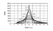
- a graph showing the relationship between the density of multi-stage surfaces and the diffraction angle.
- FIG. 3 is a plan view showing an example of arrangement of a first pixel forming a first uneven surface and a second pixel forming a second uneven surface.
- the schematic diagram which shows the relationship between the 1st range and the 2nd range at an observation angle. The schematic diagram explaining the state which an observer is observing a color display body.
- FIG. 3 is a plan view illustrating an image displayed by the first uneven surface and the second uneven surface at the second position.
- the schematic diagram which shows typically the state which receives the light reflected by a color display body using a verifier.
- the schematic diagram schematically explaining the result of machine reading using a verifier.
- FIG. 5 is a cross-sectional view showing the structure of a personal authentication medium including a color display body.
- the cross-sectional view which shows the structure of the 1st modification in a color display body.
- the embodiments of the present invention are a group of embodiments based on a single original invention. Further, each aspect of the present invention is an aspect of a group of embodiments based on a single invention.
- Each configuration of the present invention may have each aspect of the present disclosure.
- Each feature of the present invention can be combined to form each configuration. Therefore, each feature of the present invention, each configuration of the present invention, each aspect of the present disclosure, and each embodiment of the present invention can be combined, and the combination expresses a cooperative function and is synergistic. It can be effective.
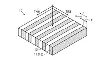
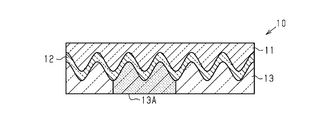
- the color display body 10 includes a resin forming mold (hereinafter, embossed layer) 11, a dielectric deposit film (hereinafter, high refractive index layer) 12, and a resin plastic protection 13 (hereinafter, high refractive index layer).
- the protective layer 13 is provided.
- the embossing layer 11, the high refractive index layer 12, and the protective layer 13 are laminated in the order described.
- Each of the layers 11, 12, and 13 has light transmission.
- the embossed layer 11 has a first refractive index n1
- the protective layer 13 has a third refractive index n3
- the high refractive index layer 12 has a second refractive index n2.
- the second refractive index n2 is higher than the first refractive index n1 and the third refractive index n3.
- the first refractive index n1 may be the same as the third refractive index n3, or may be different from the third refractive index n3.
- the variable element which contributes to the optical characteristics of the color display body 10 as compared with the case where the first refractive index n1 is the same as the third refractive index n3. It is possible to increase.
- the embossed layer 11 includes a first wavy surface (hereinafter, first uneven surface) 11S1 in at least a part of the surface 11S in contact with the high refractive index layer 12.
- first uneven surface a first wavy surface
- the period d of the first uneven surface 11S1 is included in the range of 250 nm or more and 500 nm or less.
- One concave surface and one convex surface are included in one cycle in the direction in which the concave surface and the convex surface included in the first uneven surface 11S1 are lined up, that is, in the left-right direction of the paper surface in the example shown in FIG.
- the first concavo-convex surface 11S1 has a wavy shape in a cross section orthogonal to the plane on which the color display body 10 spreads, and the wavy shape is continuous along the depth direction of the paper surface on the first concavo-convex surface 11S1.
- the high refractive index layer 12 has a thickness capable of following the surface 11S of the embossed layer 11.
- the high refractive index layer 12 has a shape that follows the surface 11S of the embossed layer 11.
- the high refractive index layer 12 may have a thickness of several nm or more and several tens of nm or less.
- the high refractive index layer 12 has a wave shape that imitates the first uneven surface 11S1, and in the high refractive index layer 12, the wave shape is the depth of the paper surface. It is continuous along the direction.
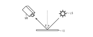
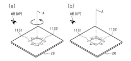
- the color display body 10 is observed by the observer OB with respect to the embossed layer 11 from the side opposite to the high refractive index layer 12.
- the observation position OP which is the position of the viewpoint of the observer OB, is an arbitrary position in the space opposite to the high refractive index layer 12 with respect to the embossed layer 11.
- the direction in which the observer OB visually recognizes the color display body 10 from the observation position OP is the line-of-sight direction DOB of the observer OB.
- the angle formed by the plane including the line-of-sight direction DOB and the plane on which the color display body 10 spreads is defined as an observation angle.
- the surface opposite to the surface 11S described above has substantially flatness. That is, the flatness of the surface opposite to the surface 11S described above is high to some extent because the surface can be treated as a flat surface.
- the specific numerical value of flatness can be measured in accordance with JIS0621-1984, and may be less than 10 mm in a square having a side of 100 mm, and further can be less than 1 mm. If the flatness is 0.1 mm or more, the surface opposite to the surface 11S may have sufficient flatness. Therefore, the observation angle can be defined as the angle formed by the plane including the line-of-sight direction DOB and the surface of the embossed layer 11 opposite to the surface 11S.
- the waveguide mode resonance that occurs in the color display body 10 will be described with reference to FIGS. 2 and 3.
- the waveguide mode resonance occurs in the color display 10 having at least three layers.
- the layer having the highest refractive index is in the center, and the layer located in the center is sandwiched between the two layers having a different refractive index from the layer located in the center. It is essential to generate waveguide mode resonance. That is, in the color display body 10, it is an essential condition that the above-mentioned high refractive index layer 12 is sandwiched between the embossing layer 11 and the protective layer 13.
- the high refractive index layer 12 is included in the waveguide layer.
- a part of the light diffracted by the high refractive index layer 12 includes the boundary between the embossed layer 11 and the high refractive index layer 12 and the high refractive index layer 12. It propagates through the high refractive index layer while being totally reflected at the boundary with the protective layer 13. Such light propagation occurs because the second refractive index n2 of the high refractive index layer 12 is higher than the first refractive index n1 of the embossed layer 11 and higher than the third refractive index n3 of the protective layer 13.
- the incident light ILs only the light having a wavelength satisfying the propagation propagation condition described below propagates through the high refractive index layer 12 as the waveguide light GL, and as a result of the propagation, it has high brightness. It is reflected in the color display as the reflected light RL. The reflected light RL is reflected in the direction of specular reflection. On the other hand, the light having a wavelength that does not satisfy the propagation condition exits from the color display body 10 as transmitted light TL transmitted through the color display body 10.
- FIG. 3 is a diagram schematically showing the color display body 10 for explaining the propagation conditions of waveguide.
- the color display body 10 when viewed from the light propagating in the color display body 10, the color display body 10 is a part of the high refractive index layer 12 in the direction in which the concave surface and the convex surface of the high refractive index layer 12 are aligned.
- the embossed layer 11 or a part of the protective layer 13 is alternately arranged. That is, the structure is such that the high bending portion and the low bending portion are alternately arranged in the direction in which the concave surface and the convex surface are arranged.
- the propagation conditions are derived from the following equation (1) using the occupancy rate F of the high refractive index layer 12 in the period d, the wavelength ⁇ of the incident light IL, the period d of the uneven surface, the wave number k, and the reciprocal lattice vector K. It can be expressed by the equation (6).
- the incident angle ⁇ of the incident light IL and the diffraction order m are integers.
- the propagation constant ⁇ of the waveguide layer, that is, the high refractive index layer 12 depends on the wavelength ⁇ of the incident light IL and the effective refractive index n eff of the high refractive index layer 12.
- Equation (1) shows the effective refractive index n eff of the high refractive index layer 12 with respect to TE waves
- equation (2) shows the effective refractive index n eff of the high refractive index layer 12 for the TM wave.
- the effective refractive index n eff of the high refractive index layer 12 when the period d of the uneven surface is shorter than the wavelength ⁇ of the incident light IL, a effective refractive index n eff for TE wave, the effective refractive index n eff for the TM wave are different from each other.
- Each effective refractive index n eff is determined by the occupancy of the high refractive index layer 12 in the period d.
- the width of the high refractive index layer 12 is a
- the width of the embossed layer 11 or the protective layer 13 is b. Therefore, the occupancy rate of the high refractive index layer 12 in the period d is the ratio of the width a to the period d, and the occupancy rate of the embossed layer 11 or the protective layer 13 in the period d is the ratio of the width b to the period d.
- n eff > n1, n3 ... Equation (7) ⁇ > d ... Equation (8)
- the wavelength of the light guided by the color display body 10 and the reflectance of the light having the wavelength by using the effective refractive index n eff. That is, by adjusting the effective refractive index n eff , it is possible to reflect chromatic light having high brightness to the color display body by using the waveguide mode resonance.
- the effective refractive index n eff and the propagation constant ⁇ are the parameters included in the equation for deriving them, that is, the first refractive index n1, the second refractive index n2, and the third refractive index.
- the waveguide layer WG that satisfies the above-mentioned propagation condition is defined by a plane that passes through the top of the embossed layer 11 and a plane that passes through the bottom of the protective layer 13.
- the waveguide layer WG can be divided into three regions in the thickness direction of the color display body 10.
- the waveguide layer WG can be divided into a first waveguide layer WG1, a second waveguide layer WG2, and a third waveguide layer WG3.
- the first waveguide layer WG1 of the color display body includes a part of the embossing layer 11 and a part of the high refractive index layer 12.
- the second waveguide layer WG2 includes a part of the embossing layer 11, a part of the high refractive index layer 12, and a part of the protective layer 13.
- the third waveguide layer WG3 includes a part of the high refractive index layer 12 and a part of the protective layer 13.
- the portion included in the first waveguide layer WG1 and the portion included in the second waveguide layer WG2 are different portions from each other.
- the portion included in the first waveguide layer WG1, the portion included in the second waveguide layer WG2, and the portion included in the third waveguide layer WG3 are different from each other.
- the portion included in the second waveguide layer WG2 and the portion included in the third waveguide layer WG3 are different portions from each other.
- the effective refractive index n eff of the first waveguide layer WG1 is derived from the relationship between the embossed layer 11 and the high refractive index layer 12 in the first waveguide layer WG1.
- the effective refractive index n eff of the second waveguide layer WG2 is derived from the relationship between the embossed layer 11, the high refractive index layer 12, and the protective layer 13 in the second waveguide layer WG2.
- the effective refractive index n eff of the third waveguide layer WG3 is derived from the relationship between the high refractive index layer 12 and the protective layer 13 in the third waveguide layer WG3.
- the intensity of the positively reflected light generated by the waveguide mode resonance is the intensity of the reflected light by the first waveguide layer WG1, the intensity of the reflected light by the second waveguide layer WG2, and the intensity of the third waveguide layer WG3. It is a superposition of the intensities of the reflected light due to.
- the second waveguide layer WG2 includes both a part of the embossing layer 11 and a part of the protective layer 13 in addition to a part of the high refractive index layer 12.
- the occupancy rate of the high refractive index layer 12 in the second waveguide layer WG2 is the occupancy rate of the high refractive index layer 12 in the first waveguide layer WG1 and the occupancy rate of the high refractive index layer 12 in the third waveguide layer WG3. It is smaller than the occupancy rate. Therefore, the contribution of the second waveguide layer WG2 to the reflectance due to the waveguide mode resonance is smaller than the contribution of the first waveguide layer WG1 and the third waveguide layer WG3.
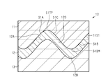
- FIG. 5 is an enlarged view of a part of the cross-sectional structure shown in FIG.
- the first uneven surface 11S1 includes a rib surface (hereinafter, convex surface) S1A, a groove surface (hereinafter, concave surface) S1B, and a tapered surface S1C.
- the convex surface S1A and the concave surface S1B are connected by the tapered surface S1C.
- the convex surface S1A is a portion including the top S1TP of one of the plurality of top S1TP included in the first uneven surface 11S1.
- the concave surface S1B is a portion including the bottom portion S1BM of one of the plurality of bottom portions S1BM included in the first concave-convex surface 11S1.
- the tapered surface S1C is neither parallel to nor perpendicular to both the convex surface S1A and the concave surface S1B.
- the convex surface S1A is a portion included in the first waveguide layer WG1
- the concave surface S1B is a portion included in the second waveguide layer WG2
- the tapered surface S1C is a portion. This is a portion straddling the first waveguide layer WG1 and the second waveguide layer WG2.
- the high refractive index layer 12 has a peak zone (hereinafter, convex portion) 12A in contact with the convex surface S1A, a valley zone (hereinafter, concave portion) 12B in contact with the concave surface S1B, and a transition zone (hereinafter, tapered surface portion) in contact with the tapered surface S1C. Contains 12C.
- the convex surface portion 12A is a portion included in the first waveguide layer WG1, and the concave surface portion 12B is formed into the second waveguide layer WG2 and the third waveguide layer WG3.
- the tapered surface portion 12C is a portion that straddles the first waveguide layer WG1 and the second waveguide layer WG2.
- the high refractive index layer 12 includes a convex surface portion 12A, a concave surface portion 12B, and a tapered surface portion 12C in which at least one of the thickness and the volume density is different from the others.
- the color display body 10 formed of the embossed layer 11, the high refractive index layer 12, and the protective layer 13 includes the first waveguide layer WG1, the second waveguide layer WG2, and the third waveguide. Includes layer WG3.
- the first waveguide layer WG1 is formed by a part of the embossing layer 11 and a part of the high refractive index layer 12
- the second waveguide layer WG2 is a part of the embossing layer 11 and one of the high refractive index layers 12.
- the third waveguide layer WG3 is formed by a part of the high refractive index layer 12 and a part of the protective layer 13.
- the convex surface portion 12A is mainly included in the first waveguide layer WG1
- the concave surface portion 12B is mainly included in the third waveguide layer WG3
- the tapered surface portion 12C is mainly included in the second guide. It is included in the waveguide WG2.
- the ratio occupied by the high refractive index layer 12 contributes to the value of the effective refractive index n eff in the waveguide layers WG1, WG2, WG3.
- the effective refractive index n eff of each waveguide layer WG1, WG2, WG3 when at least one of the thickness and the volume density of the high refractive index layer 12 is uniform in the entire high refractive index layer 12 is used as a reference value. ..
- the value of the effective refractive index n eff can be set to a value different from the reference value.
- the wavelength of the reflected light RL derived from the waveguide layers WG1, WG2, WG3 is determined by the value of the effective refractive index n eff in each waveguide layer WG1, WG2, WG3, the thickness and volume of the high refractive index layer 12 It is possible to adjust the wavelength of the reflected light RL derived from each waveguide layer WG1, WG2, WG3 by at least one of the densities. As a result, it is possible to diversify the wavelength of light reflected by the color display by waveguide mode resonance, depending on the number and location of the parts whose thickness and volume density have been changed.
- the high refractive index layer 12 includes a plurality of convex surface portions 12A, a plurality of concave surface portions 12B, and a plurality of tapered surface portions 12C, and at least a part of all of them has at least one of the thickness and the volume density. May be different from some others.
- both the thickness and the volume density may be the same in all the convex portions 12A, or at least one of the thickness and the volume density in at least a part of the plurality of convex portions 12A. May be different from some others.
- both the thickness and the volume density may be the same in all the concave surface portions 12B, and in at least a part of the plurality of concave surface portions 12B, the thickness and the volume density may be the same. At least one may differ from the other part.
- both the thickness and the volume density may be the same in all the tapered surface portions 12C, and at least a part of the plurality of tapered surface portions 12C may have the same thickness and volume density. At least one may differ from the other part.
- the occupancy rate of the high refractive index layer 12 in each waveguide layer WG1, WG2, WG3 changes by changing the thickness of the high refractive index layer 12.
- the effective refractive index n eff in each waveguide layer WG1, WG2, WG3 changes.
- the wavelength of the light guided in each of the waveguide layers WG1, WG2, WG3, and eventually the wavelength of the reflected light RL reflected by the color display body 10 changes.
- the color of the light reflected by the color display body 10 changes.
- the occupancy rate of the high refractive index layer 12 in each of the waveguide layers WG1, WG2, and WG3 tends to increase as the thickness of the high refractive index layer 12 increases. Further, the occupancy rate of the high refractive index layer 12 in each waveguide layer WG1, WG2, WG3 tends to decrease as the thickness of the high refractive index layer 12 decreases.
- each convex surface portion 12A larger than the thickness of each concave surface portion 12B and the thickness of each tapered surface portion 12C (change 1)
- the high refractive index in the first waveguide layer WG1 is obtained. It is possible to increase the occupancy rate of the rate layer 12.
- the thickness of each concave surface portion 12B larger than the thickness of each convex surface portion 12A and the thickness of each tapered surface portion 12C (change 2)
- the high refractive index in the third waveguide layer WG3 is obtained. It is possible to increase the occupancy rate of the rate layer 12.
- each tapered surface portion 12C can be made thicker than the thickness of each convex surface portion 12A and the thickness of each concave surface portion 12B (change 3). Further, in change 1, the thickness of each tapered surface portion 12C can be made thicker than the thickness of each concave surface portion 12B. Further, in change 2, the thickness of each tapered surface portion 12C can be made thicker than the thickness of each convex surface portion 12A.
- the refractive index of the high refractive index layer 12 changes as the volume density of the high refractive index layer 12 changes.
- the effective refractive index n eff in each waveguide layer WG1, WG2, WG3 changes.
- the wavelength of the light guided in each of the waveguide layers WG1, WG2, WG3, and eventually the wavelength of the reflected light RL reflected by the color display body 10 changes.
- the color of the light reflected by the color display body 10 changes.
- the refractive index of the high refractive index layer 12 tends to increase as the volume density increases. Further, the refractive index of the high refractive index layer 12 tends to decrease as the volume density decreases.
- each convex surface portion 12A higher than the volume density of each concave surface portion 12B and the volume density of each tapered surface portion 12C
- the effective refractive index n eff in the first waveguide layer WG1 is increased.
- the volume density of each concave surface portion 12B higher than the volume density of each convex surface portion 12A and the volume density of each tapered surface portion 12C
- the effective refractive index n eff in the third waveguide layer WG3 is obtained. Can be changed.
- the first waveguide layer WG1 and the second waveguide layer are formed.
- the effective refractive index n eff in WG2 can be changed.
- FIG. 6 is an SEM image of the cross-sectional structure of an example of the color display body 10 taken by a scanning electron microscope (SEM).
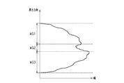
- FIG. 7 is a graph showing the relationship between the thickness direction of the color display body 10 and the width of the high refractive index layer 12 in the high refractive index layer 12 included in the SEM image shown in FIG.
- the width of the high refractive index layer 12 is the length of the high refractive index layer 12 in the direction in which the irregularities are lined up. That is, FIG. 7 shows a transition along the thickness of the color display body 10 in the width of the high refractive index layer 12.
- the third waveguide layer WG3 is the sum of the widths of the portions included in each waveguide layer WG1, WG2, WG3 in the high refractive index layer 12.
- the sum of the widths of the portions included in the first waveguide layer WG1 is referred to as the first sum
- the sum of the widths of the portions included in the second waveguide layer WG2 is referred to as the second sum
- the sum of the widths of the portions included in is referred to as the third sum.
- the color display body 10 includes an embossing layer 11, a high refractive index layer 12, and a protective layer 13.
- the high refractive index layer 12 has a thickness capable of having a shape that follows the surface 11S of the embossed layer 11.
- the surface 11S of the embossed layer 11 has a substantially sine-wave cross-sectional shape
- the high refractive index layer 12 has a substantially sine-wave cross-sectional shape similar to the surface 11S of the embossed layer 11.
- the maximum value of the third sum is larger than the maximum value of the first sum.
- the second sum is equal to the maximum value of the first sum at the boundary with the portion included in the first waveguide layer WG1
- the third sum is equal to the maximum value of the third sum at the boundary with the portion included in the third waveguide layer WG3. Equal to the maximum value.
- the third sum decreases in the direction from the surface in contact with the protective layer 13 to the surface in contact with the embossed layer 11.
- the first sum increases in the direction from the surface in contact with the embossed layer 11 to the surface in contact with the protective layer 13.
- the second sum has a minimum value substantially in the middle between the surface in contact with the embossed layer 11 and the surface in contact with the protective layer 13.
- the width of the concave surface S1B is larger than the width of the convex surface S1A. Therefore, the maximum value of the third sum is larger than the maximum value of the first sum.
- FIG. 8 shows a plurality of examples of the cross-sectional shape of the color display body 10.
- the first uneven surface 11S1 has a wavy shape.
- the width of the convex surface S1A is the convex surface width WA1
- the width of the concave surface S1B is the concave surface width WB1.
- the convex width WA1 is equal to the concave width WB1.
- the distance between the top S1TP and the bottom S1BM in the thickness direction of the color display body 10 is the height H1 of the first uneven surface 11S1.
- the thickness T of the high refractive index layer 12 is substantially constant throughout the high refractive index layer 12.
- the convex surface width WA1 is equal to the concave surface width WB1 as in the color display body 10A.
- the height H2 of the first uneven surface 11S1 is larger than the height H1 in the color display body 10A.
- the thickness of the second waveguide layer WG2 is thicker than that of the color display body 10A.
- the occupancy rate of the waveguide layer increases in the thickness direction of the color display body 10B.
- the occupancy rate of the embossed layer 11 and the protective layer 13 is high, while the occupancy rate of the high refractive index layer 12 is low.
- the effective refractive index n eff of the color display member 10B is lower than the effective refractive index n eff of the color display body 10A.
- the first uneven surface 11S1 of the color display body 10 can include a first wavy portion (hereinafter, first uneven portion). As described above, the distance between the top portion S1TP included in the convex surface S1A and the bottom portion S1BM included in the concave surface S1B adjacent to the convex surface S1A is the height of the first uneven surface 11S1. In the first uneven portion, the height of the first uneven surface 11S1 can include a first value and a second value different from the first value.
- the first concavo-convex portion can include both the first concavo-convex surface 11S1 of the color display body 10A and the first concavo-convex surface 11S1 of the color display body 10B in one surface 11S.
- the first concavo-convex portion waveguide is performed between the portion where the height of the first concavo-convex surface 11S1 is the first value and the portion where the height of the first concavo-convex surface 11S1 is the second value.
- the effective refractive index n eff in the layer can be changed. Therefore, light having a wavelength different from that in the case where the effective refractive index n eff in the first uneven portion is uniform can be reflected by the first uneven portion.
- the height H1 of the first uneven surface 11S1 is equal to the height H1 of the first uneven surface 11S1 in the color display body 10A.
- the convex surface width WA2 is smaller than the convex surface width WA1 in the color display body 10A.
- the concave surface width WB2 is smaller than the concave surface width WB1 in the color display body 10A, and the concave surface width WB2 is equal to the convex surface width WA2.
- the frequency with which the high refractive index layer 12 is included in each of the waveguide layers WG1, WG2, and WG3 increases.
- the effective refractive index n eff of the waveguide layer WG in the color display body 10C is higher than the effective refractive index n eff of the waveguide layer WG in the color display body 10A.
- the first uneven surface 11S1 of the color display body 10 can include a second wavy portion (hereinafter referred to as a second uneven portion).
- the second uneven portion can include a convex surface S1A having a first width and a concave surface S1B having a second width different from the first width in the direction in which the convex surface S1A and the concave surface S1B are aligned.
- the second concavo-convex portion can include a convex surface S1A included in the first concavo-convex surface 11S1 of the color display body 10A and a concave surface S1B included in the first concavo-convex surface 11S1 of the color display body 10C.
- the second concavo-convex portion can include a concave surface S1B included in the first concavo-convex surface 11S1 of the color display body 10A and a convex surface S1A included in the first concavo-convex surface 11S1 of the color display body 10C.
- the second uneven portion can include the convex surface S1A having the first width and the concave surface S1B having the second width.
- the second uneven portion has an effective refractive index different from the case where the width of the convex surface S1A and the width of the concave surface S1B are uniform. It is possible to have n eff. Therefore, the second uneven portion can reflect light having a wavelength different from the case where the width of the convex surface S1A and the width of the concave surface S1B are uniform.
- the width of the convex surface S1A is larger than the width of the concave surface S1B in the direction in which the convex surface S1A and the concave surface S1B are aligned. You may.
- the convex surface portion 12A in contact with the convex surface S1A mainly contributes to the value of the effective refractive index n eff of the first waveguide layer WG1, while the concave surface portion 12B in contact with the concave surface S1B is mainly the third guide.
- the occupancy rate of the high refractive index layer 12 in the first waveguide layer WG1 is higher than that when the width of the convex surface S1A and the width of the concave surface S1B are equal. 3 It is possible to increase the occupancy rate of the high refractive index layer 12 in the waveguide layer WG3.
- the effective refractive index n eff of the first waveguide layer WG1, the difference between the effective refractive index n eff of the third waveguide layer WG3, the above difference between the first refractive index n1 and a third refractive index n3 It can be made larger.
- the difference between the wavelength of the light waved by the first waveguide layer WG1 and the wavelength of the light waved by the third waveguide layer WG3 is also the first refractive index n1 and the third refractive index n3. It becomes larger than the difference of.
- the elastic modulus of the embossed layer 11 may be lower than the elastic modulus of the protective layer 13 in order to ensure the moldability of the embossed layer 11.
- the width of the convex surface S1A is larger than the width of the concave surface S1B, so that the curvature of the convex surface S1A can be made smaller than the curvature of the concave surface S1B.
- the concentration of stress on the convex surface S1A is suppressed, and as a result, the high refractive index layer 12 is suppressed from being peeled off from the embossed layer 11.
- the elastic modulus of the protective layer 13 has a higher elastic modulus than that of the embossed layer 11, stress concentration in the protective layer 13 is less likely to occur due to the elastic modulus of the protective layer 13. Therefore, peeling between the protective layer 13 and the high refractive index layer 12 is unlikely to occur.
- the first uneven surface 11S1 has a wavy shape.
- the width WA3 of the convex surface S1A is smaller than the width WB3 of the concave surface S1B in the direction in which the convex surface S1A and the concave surface S1B are aligned, as in the structure shown in FIG.
- the curvature of the concave surface S1B is smaller than the curvature of the convex surface S1A.
- the thickness of the concave surface portion 12B following the concave surface S1B in the high refractive index layer 12 is the convex surface S1A. It tends to be thicker than the thickness of the convex surface portion 12A that follows. More specifically, when the high refractive index layer 12 is formed on the embossed layer 11 by, for example, a vacuum deposition method, particles are likely to be deposited on the concave surface S1B having a relatively small curvature, but relatively. Particles are less likely to deposit on the convex surface S1A having a large curvature.
- the thickness of the concave surface portion 12B tends to be thicker than the thickness of the convex surface portion 12A. Further, in this case, since the curvature of the concave surface S1B, which is difficult to be filled with the resin at the time of embossing, can be increased, the embossing layer 11 can be easily formed.
- the width of the convex surface S1A is smaller than the width of the concave surface S1B in the direction in which the convex surface S1A and the concave surface S1B are aligned. You may.
- the high refractive index in the first waveguide layer WG1 is compared with the case where the width of the convex surface S1A and the width of the concave surface S1B are equal.
- the occupancy of the layer 12 can be made higher than the occupancy of the high refractive index layer 12 in the third waveguide layer WG3.
- the effective refractive index n eff of the first waveguide layer WG1, the difference between the effective refractive index n eff of the third waveguide layer WG3, the above difference between the first refractive index n1 and a third refractive index n3 It can be made larger.
- the difference between the wavelength of the light waved by the first waveguide layer WG1 and the wavelength of the light waved by the third waveguide layer WG3 is also the first refractive index n1 and the third refractive index n3. It becomes larger than the difference of.
- FIG. 9 shows a plurality of structures in the cross-sectional shape of the color display body 10.
- FIG. 8 referred to earlier illustrates two color display bodies 10A and 10B having different heights of the first concave-convex surface 11S1 and color display bodies 10A and 10C having different convex surface widths and concave surface widths. ..
- FIG. 9 referred to below shows a color display body in which the concave surface shape and the convex surface shape are different from each other.
- the first concave-convex surface 11S1 includes a plurality of convex surfaces S1A, a plurality of concave surfaces S1B, and a plurality of tapered surfaces S1C.
- the convex surface S1A and the concave surface S1B adjacent to the convex surface S1A are connected by the tapered surface S1C.
- the convex surface S1A, the tapered surface S1C, the concave surface S1B, and the tapered surface S1C are arranged in the order described.
- the surface group formed by the convex surface S1A, the tapered surface S1C, the concave surface S1B, and the tapered surface S1C is repeated along one direction.
- the surface of the embossed layer 11 having a small distance from the surface opposite to the first concavo-convex surface 11S1 is the convex surface S1A, and the distance from the surface opposite to the first concavo-convex surface 11S1.
- the surface with a large size is the concave surface S1B.
- the shape of the convex surface S1A is equal to the shape of the concave surface S1B.
- the convex surface S1A and the concave surface S1B are developable surfaces (developed curved surfaces), respectively.
- the developable surface is a curved surface formed by the movement of a straight line. On the developable surface, the curvature of Gauss at all points on the developable surface is "0".
- the convex surface S1A and the concave surface S1B have a substantially semicircular shape and are formed from a plurality of straight lines in a cross section orthogonal to the plane on which the color display body 10E spreads and orthogonal to the direction in which the convex surface S1A extends. ing. Therefore, the design and manufacture of the color display body 10E is easier than in the case where the convex surface S1A and the concave surface S1B are double curved surfaces.
- the double curved surface is a curved surface having no linear component.
- the tapered surface S1C has a linear approximation curve in a cross section orthogonal to the plane on which the color display body 10E spreads and orthogonal to the direction in which the convex surface S1A extends.
- the tapered surface S1C is not parallel to the convex surface S1A and the concave surface S1B, and is not perpendicular to the respective surfaces S1A and S1B.
- the tapered surface S1C is a forward tapered surface, but the tapered surface S1C may be a reverse tapered surface.
- the first uneven surface 11S1 has a tapered surface S1C as a surface connecting the convex surface S1A and the concave surface S1B, a first surface orthogonal to the plane on which the color display body 10E spreads is provided in place of the tapered surface S1C.
- the accuracy of the shape of the uneven surface 11S1 is enhanced. More specifically, when the embossed layer 11 is formed using the original plate, the resin formed by the original plate is easily separated from the original plate.
- the shape of the convex surface S1A is equal to the shape of the concave surface S1B.
- the convex surface S1A and the concave surface S1B each have a linear shape in a cross section orthogonal to the plane on which the color display body 10F spreads and orthogonal to the direction in which the convex surface S1A extends.
- the convex surface S1A and the concave surface S1B are substantially parallel to the surface of the embossed layer 11 opposite to the first uneven surface 11S1.
- the tapered surface S1C has a linear approximation curve in a cross section orthogonal to the plane on which the color display body 10F spreads and orthogonal to the direction in which the convex surface S1A extends.
- the tapered surface S1C is a forward tapered surface, but it may be a reverse tapered surface.
- the shape of the convex surface S1A and the shape of the concave surface S1B may be different from each other.
- the color display body 10 may include a convex surface S1A of the color display body 10E and a concave surface S1B of the color display body 10F.
- the color display body 10 may include a concave surface S1B of the color display body 10E and a convex surface S1A of the color display body 10F.
- the color display body 10 may include two types of convex surfaces S1A and two types of concave surfaces S1B.
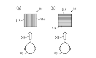
- FIG. 10 shows the relationship between the line-of-sight direction DOB of the observer OB and the azimuth angle of the first uneven surface 11S1.
- the direction in which the straight line shown in the color display body 10 extends is the direction in which the convex surface S1A extends.
- the convex surface S1A included in the color display body 10 extends along one direction.
- the convex surface S1A extends along the vertical direction of the paper surface.
- the azimuth angle of the first uneven surface 11S1 is an angle formed by a direction in which the convex surface S1A extends and a reference direction which is an arbitrary direction along a plane on which the color display body 10 spreads.
- the reference direction is set to the left-right direction of the paper surface.
- the angle formed by the reference direction and the direction in which the convex surface S1A extends is 90 °. Therefore, the azimuth angle of the first uneven surface 11S1 is 90 °.
- the projection direction in which the line-of-sight direction DOB of the observer OB is projected onto the plane on which the color display body 10 spreads is the vertical direction of the paper surface.
- the projection direction is parallel to the extending direction of the convex surface S1A. That is, the first uneven surface 11S1 is vertically oriented with respect to the observer OB.
- the convex surface S1A extends along the left-right direction of the paper surface. Since the left-right direction of the paper surface is the reference direction, the angle formed by the reference direction and the direction in which the convex surface S1A extends is 0 °. Therefore, the azimuth angle of the first uneven surface 11S1 is 0 °.
- the projection direction in which the line-of-sight direction DOB of the observer OB is projected onto the plane on which the color display body 10 spreads is the vertical direction of the paper surface.
- the projection direction is orthogonal to the extending direction of the convex surface S1A. That is, the first uneven surface 11S1 is oriented sideways with respect to the observer OB.
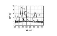
- FIG. 11 shows the relationship between the wavelength of the reflected light RL reflected by the color display body 10 and the reflectance.
- the spectrum shown by the solid line is the spectrum obtained by the color display body 10 in which the first uneven surface 11S1 is in the vertical direction
- the spectrum shown by the broken line is the spectrum in which the first uneven surface 11S1 is arranged in the horizontal direction. It is a spectrum obtained by the color display body 10.
- the direction from the light receiving element included in the measuring device toward the color display body 10 is set as the measuring direction, and the measuring direction is regarded as the above-mentioned line-of-sight direction DOB.
- the spectrum R of either the color display body 10 in which the first uneven surface 11S1 is arranged vertically or the color display body 10 in which the first uneven surface 11S1 is arranged horizontally It is possible to reflect the red light shown by, the green light shown by spectrum G, and the blue light shown by spectrum B.
- the peak intensities of the spectra R, G, and B shown by the solid line are higher than the peak intensities of the spectra R, G, and B shown by the broken line. Therefore, in the color display body 10, it is preferable that the first uneven surface 11S1 is oriented vertically with respect to the observer OB.
- the color display body 10 is configured to be able to display a predetermined image to the observer OB when the first uneven surface 11S1 is oriented vertically.
- a predetermined image can be displayed by a difference in structure in the color display body 10, that is, a motif formed by a plurality of structures different from each other.
- the motif can be formed by the difference in the structure of the color display body 10, and the motif can display an image.
- the color display body 10 may have a plurality of different regions having different structures.
- FIGS. 12 and 13 show the relationship between the wavelength of the reflected light RL reflected by the color display body 10 and the reflectance, as in FIG.
- the spectrum when the position of the color display body 10 is tilted by 20 ° with respect to the reference position is shown by a solid line
- the spectrum when tilted by 30 ° is shown by a broken line, which is tilted by 40 °.
- the spectrum at that time is shown by the alternate long and short dash line.
- the position of the color display body 10 when the color display body 10 is positioned on a horizontal plane is the reference position.
- FIG. 12 is a spectrum obtained by the color display body 10 arranged vertically.
- FIG. 13 is a spectrum obtained by the color display body 10 arranged sideways.
- the color display body 10 is tilted by 20 ° with respect to the reference position and 40 ° with respect to the reference position.
- the difference in wavelength between the peaks is less than 50 nm.
- the color display body 10 in which the first uneven surface 11S1 is oriented sideways as shown in FIG. 13, the color display body 10 is tilted by 20 ° with respect to the reference position and 40 ° with respect to the reference position.
- the difference in wavelength at the peak is 50 nm or more and less than 100 nm.
- the color display body 10 refers to the observer OB. Therefore, it is preferable that the first uneven surface 11S1 is oriented vertically. In other words, it is preferable that the color display body 10 is configured to be able to display a predetermined image on the observer OB when the first uneven surface 11S1 is oriented vertically.
- the reflected light RL of the color display body 10 may include primary diffracted light.
- the primary diffracted light is reflected on a plane orthogonal to the direction in which the convex surface S1A extends and orthogonal to the plane on which the color display body 10 spreads. Therefore, when the color display body 10 has the first uneven surface 11S1 sideways with respect to the observer OB, the observer OB may visually recognize the primary diffracted light reflected by the color display body 10. Further, the observer OB may mistakenly recognize the first-order refracted light that he / she sees as the 0th-order diffracted light, that is, the reflected light RL due to the waveguide mode resonance. When the color display body 10 is oriented vertically with respect to the observer OB, it is possible to reduce the possibility that the observer OB mistakenly recognizes the first-order diffracted light as the 0th-order diffracted light. Is.
- a part of the surface 11S of the embossed layer 11 is the first uneven surface 11S1.
- the region including the center of the surface 11S is the first uneven surface 11S1.
- the first refractive index n1 of the embossed layer 11 is equal to the third refractive index n3 of the protective layer 13.
- the first uneven surface 11S1 is formed of a first region R1 and a second region R2.
- the second region R2 is formed of a region having an O-shape of the alphabet and a region having a K-shape of the alphabet.
- the first region R1 has a shape surrounding the second region R2.
- the period of the unevenness in the first region R1 is equal to the period of the unevenness in the second region R2.
- the effective refractive index n eff of the first waveguide layer WG1 the first region R1 includes, the effective refractive index n eff of the third waveguide layer WG3 the first region R1 includes, and, first electrically contained in the second region R2 It is equal to the effective refractive index n eff of the waveguide WG1.
- the effective refractive index n eff of the first waveguide layer WG1 included in the first region R1 is different from the effective refractive index n eff of the third waveguide layer WG3 included in the second region R2.
- the above-mentioned changes 1, change 2, and change 3 can increase the occupancy of the high refractive index layer 12 in the first waveguide layer WG1 and the second waveguide layer WG2 in the first region R1 and the second region R2. Is. Thereby, the effective refractive index of the first waveguide layer WG1 and the second waveguide layer WG2 can be increased.
- the spectrum of the zero-order diffracted light reflected by the first region R1 may have a monomodal property.
- the spectrum of the zero-order diffracted light reflected by the first region R1 may have bimodality.
- the observer OB when the observer OB observes the color display body 10, the observer OB can observe the zero-order diffracted light reflected by the waveguide mode resonance in the direction of specular reflection.
- the incident angle ⁇ of the incident light IL is equal to the reflection angle ⁇ of the zero-order diffracted light which is the reflected light RL.
- the wavelength of the reflected light RL is included in the visible light range, whereby the color display body 10 can display a chromatic image.
- FIG. 16 is an example of the spectrum of the zero-order diffracted light reflected by the color display body 10.
- the spectrum of the zero-order diffracted light reflected by the color display body 10 may have bimodality.
- the peak with the highest reflection intensity is the first peak P1
- the peak with the second highest reflection intensity is the second peak P2.
- the spectrum of zero-order diffracted light has a first peak P1 at about 470 nm and a second peak P2 at about 460 nm.
- the first peak P1 is reflected by the waveguide in each of the first waveguide layer WG1 in the first region R1, the third waveguide layer WG3 in the first region R1, and the first waveguide layer WG1 in the second region R2. It is a peak derived from the reflected light RL.
- the second peak P2 is a peak derived from the reflected light RL reflected by the waveguide in the third waveguide layer WG3 of the second region R2.
- the effective refractive index n eff of the first waveguide layer WG1, the effective refractive index n eff of the third waveguide layer WG3 are different from each other.
- the observer OB of the color display body 10 separates the reflected light RL reflected by the color display body 10 into the reflected light RL corresponding to the first peak P1 and the reflected light RL corresponding to the second peak P2. I can't. Therefore, the observer OB visually recognizes one image having one chromatic color by observing the color display body 10.
- FIG. 17 is a spectrum of zero-order diffracted light reflected by another color display body.
- the spectrum of the zero-order diffracted light reflected by the color display may be monomodal.
- the spectrum has a third peak P3 at about 470 nm and no other peaks.
- the color display body that reflects the zero-order diffracted light having the spectrum shown in FIG. 17, it was reflected by the waveguide in each of the first waveguide layer WG1, the second waveguide layer WG2, and the third waveguide layer WG3.
- the wavelengths of the reflected light RL are equal to each other.
- the effective refractive index n eff of the first waveguide layer WG1 the effective refractive index n eff of the third waveguide layer WG3 are equal to each other.
- the color display body can have a structure capable of reflecting zero-order diffracted light having a spectrum having multimodality, and also has a zero-order spectrum having a monomodal spectrum. It is also possible to have a structure capable of reflecting the folding light.
- the verification machine VM As shown in FIG. 18, it is also possible to verify the authenticity of the color display body 10 by using the verification machine VM. As described above, the zero-order diffracted light is reflected in the direction of specular reflection. Therefore, even when the verification machine VM is used, the color display body 10 and the verification machine VM are arranged at positions where the specularly reflected light of the color display body 10 can be received.
- FIG. 19 is an image formed by the light received by the verification machine VM.
- the verification machine VM can separate the reflected light RL corresponding to the first peak P1 and the reflected light RL corresponding to the second peak P2. Therefore, in the image obtained by the verification machine VM, the first region R1 is separated from the second region R2.
- the verifier VM may be able to detect the light reflected by the first region R1, but may not be able to detect the light reflected by the second region R2. Even in this case, in the image obtained by the verification machine VM, the first region R1 is separated from the second region R2.
- the first region R1 and the second region R2 of the color display body 10 cannot be visually separated, while the first region R1 and the second region R2 are separated by the verification machine VM. It is possible to separate by. Authenticity can be verified by the first region R1, the second region R2, or both separated by the verification machine VM. Further, it is possible to visually detect a counterfeit product of the color display body 10 by the color development of the color display body 10. Therefore, the authenticity of the color display body 10 can be determined visually and by the verification machine VM. Therefore, the color display body 10 can be used to prevent forgery of the article to which the color display body 10 is attached.
- a part of the convex surface portion 12A, the concave surface portion 12B, and the tapered surface portion 12C included in the high refractive index layer 12 has a thickness different from the thickness of the other part. It is possible to have and to have a volume density different from that of other parts.
- the effective refractive index n eff in each of the waveguide layers WG1, WG2, and WG3 can be made equal to each other between the first waveguide layer WG1, the second waveguide layer WG2, and the third waveguide layer WG3. , It is possible to make them different from each other.
- the light reflected by the color display body 10 in other words, the entire image displayed by the color display body 10 may exhibit one color according to the effective refractive index n eff , or a part of the image may have another color. It is possible to give a different color to the part.
- the color display body 10 reflects according to the purpose of the color display body 10, the environment in which the color display body 10 is used, and the functions expected of the color display body 10. It is possible to increase the variety in the color of light.
- the method for manufacturing the color display body 10 includes a step of creating a stamper (step S11), a step of forming an embossed layer 11 (step S12), and a step of forming a high refractive index layer 12 (step S13). ), And the step of forming the protective layer 13 (step S14).
- the original plate is created by lithography using electron beam drawing.
- a positive resist material is prepared.
- a resist layer is formed with the resist material.
- the resist layer is irradiated with an electron beam according to the shape of the surface 11S of the embossed layer 11. Since the resist layer is formed of a positive resist, the portion of the resist layer to be removed from the resist layer after development is irradiated with an electron beam.
- the portion irradiated with the electron beam is removed from the developed resist layer. Therefore, in the developed resist layer, the flatness of the portion irradiated with the electron beam is lower than the flatness of the portion not irradiated with the electron beam.
- the embossed layer 11 is formed by using the original plate having a portion having a low flatness, the flatness of the portion formed by the transfer of the portion of the original plate having a low flatness in the embossed layer 11 is also lowered.
- the portion of the embossed layer 11 having a low flatness light scattering occurs as compared with the portion having a higher flatness, and waveguide mode resonance is less likely to occur. As a result, the intensity of the reflected light RL reflected by the color display body 10 becomes low.
- a stamper for transferring the uneven shape of the original plate to the embossed layer is created from the original plate by electroforming. Then, the embossed layer 11 is formed by transferring the uneven shape of the stamper to the resin layer for forming the embossed layer 11. Therefore, in the embossed layer 11, the flatness of the convex surface S1A is lower than the flatness of the concave surface S1B.
- the thickness of the convex surface portion 12A is the peak thickness (hereinafter, convex surface thickness)
- the thickness of the concave surface portion 12B is the valley thickness (hereinafter, concave surface thickness)
- the convex surface portion 12A is the peak thickness (hereinafter, convex surface density)
- the concave surface density is the peak density (hereinafter, convex surface density)
- the concave surface density can be thicker than the convex surface thickness, or the concave surface density can be higher than the convex surface density.
- the third waveguide layer WG3 including the concave surface S1B is lighter than the first waveguide layer WG1 including the convex surface S1A. It is possible to increase the efficiency of waveguide. Therefore, it is possible to prevent the low flatness of the convex surface S1A from lowering the intensity of the reflected light RL of the color display body 10.
- a synthetic resin for forming the embossed layer 11 is prepared.
- the synthetic resin for forming the embossed layer 11 may be a thermoplastic resin, a thermosetting resin, or a photocurable resin.
- the synthetic resin is, for example, an acrylic resin, a urethane resin, or a urethane acrylic resin. Then, after applying the coating film containing the synthetic resin for forming the embossing layer 11, the embossing layer 11 can be obtained by transferring the uneven shape of the transfer plate to the coating film.
- the high refractive index layer 12 is formed so as to cover the surface 11S of the embossed layer 11.
- the dielectric material for forming the high refractive index layer 12 may be a metal compound, silicon oxide (SiO 2 ), or the like.
- the metal compound may be a metal oxide, a metal sulfide, a metal fluoride, or the like.
- the metal compounds are, for example, zinc oxide (ZnO), titanium oxide (TIO 2 ), zinc sulfide (ZnS), and magnesium fluoride (MgF).
- TiO 2 has a high refractive index, and therefore TiO 2 is suitable as a material for forming the high refractive index layer 12.
- the volume density of TiO 2 may be changed from the first value to the second value. Assuming that the thickness of the high refractive index layer 12 is the same, the higher the volume density of the TiO 2 forming the high refractive index layer 12, the higher the refractive index of the high refractive index layer 12.
- the high refractive index layer 12 can be formed by using a deposition method.
- the deposition method may be a chemical volume method or a physical deposition method.
- the physical deposition method may be, for example, a sputtering method, a vacuum deposition method, or the like. Regardless of which deposition method is used, the film-forming species easily reach the concave surface S1B of the embossed layer 11, while the film-forming species do not easily reach the convex surface S1A of the embossed layer 11. Therefore, in the high refractive index layer 12, the concave surface thickness of the concave surface portion 12B tends to be thicker than the convex surface thickness of the convex surface portion 12A. Therefore, making the concave surface thickness thicker than the convex surface thickness is easier than making the convex surface thickness thicker than the concave surface thickness.
- a synthetic resin for forming the protective layer 13 is prepared.
- the synthetic resin for forming the protective layer 13 may be a synthetic resin that can be used for forming the embossed layer 11. After preparing a coating film containing a synthetic resin for forming the protective layer 13, the coating film is applied to the high refractive index layer 12 so as to cover the high refractive index layer 12. Then, by curing the coating film, it is possible to obtain the color display body 10 having the protective layer 13.
- the thickness of the high refractive index layer 12 is determined by the value of the effective refractive index n eff in each waveguide layer WG1, WG2, WG3, because the wavelength of the reflected light RL derived from the waveguide layers WG1, WG2, WG3 is determined. It is possible to adjust the wavelength of the reflected light RL derived from each waveguide layer WG1, WG2, WG3 by at least one of the sword and the volume density. As a result, it is possible to diversify the wavelength of light reflected by the color display by waveguide mode resonance, depending on the number and position of the parts whose thickness and volume density have been changed.
- waveguide is performed between a portion where the height of the first concavo-convex surface 11S1 is the first value and a portion where the height of the first concavo-convex surface 11S1 is the second value.
- the effective refractive index n eff in the layer can be changed. Therefore, light having a wavelength different from that in the case where the refractive index in the first uneven portion is uniform can be reflected by the first uneven portion.
- the second uneven portion is different from the case where the width of the convex surface S1A and the width of the concave surface S1B are uniform. It is possible to have an effective index of refraction n eff. Therefore, the second uneven portion can reflect light having a wavelength different from the case where the width of the convex surface S1A and the width of the concave surface S1B are uniform.
- the effective refractive index n eff of the first waveguide layer WG1, the difference between the effective refractive index n eff of the third waveguide layer WG3, the above difference between the first refractive index n1 and a third refractive index n3 It can be made larger.
- the difference between the wavelength of the light waved by the first waveguide layer WG1 and the wavelength of the light waved by the third waveguide layer WG3 is also the first refractive index n1 and the third refractive index n3. It becomes larger than the difference of.
- the first waveguide layer WG1 including the convex surface S1A It is possible to increase the efficiency of light waveguide. Therefore, it is possible to prevent the low flatness of the convex surface S1A from lowering the brightness of the reflected light RL of the color display body 10.
- a second embodiment of the color display body, the authentication medium, and the method for determining the authenticity of the color display body will be described with reference to FIGS. 21 to 31.
- the color display body of the second embodiment is different from the color display body 10 of the first embodiment in that it further includes an uneven surface having a shape different from that of the uneven surface of the color display body 10 of the first embodiment. ing. Therefore, in the following, the differences between the color display body of the second embodiment and the color display body 10 of the first embodiment will be described in detail.
- the configuration common to the color display body 10 of the first embodiment is designated by the same reference numerals as the color display body 10 of the first embodiment. Detailed explanation is omitted. Further, in the following, the actions of the embossing layer, the color display body, and the color display body will be described in order.
- FIG. 21 shows a part of the cross-sectional structure of the embossed layer 11.
- the cross-sectional structure shown in FIG. 21 is orthogonal to the plane on which the color display body spreads, and is orthogonal to the direction in which the convex surface S1A of the first concave-convex surface 11S1 described above extends.
- the surface 11S of the embossed layer 11 includes the second uneven surface 11S2.
- the surface 11S of the embossed layer 11 includes the second uneven surface 11S2 in addition to the first uneven surface 11S1 described above.
- the second uneven surface 11S2 has a plurality of multi-stage surfaces S2A including a plurality of stages. On the second uneven surface 11S2, a plurality of multi-stage surfaces S2A are lined up at a predetermined period d.
- the period d of the multi-stage surface S2A is longer than the period d of the first concavo-convex surface 11S1 and is a period of reflecting the first-order diffracted light. Since the surface 11S of the embossing layer 11 has the first uneven surface 11S1 and the second uneven surface 11S2, the collar including the embossing layer 11 is compared with the case where the surface 11S of the embossing layer 11 has only the first uneven surface 11S1. It is difficult to forge the display.
- the direction in which the plurality of multi-stage surfaces S2A are arranged and the direction in which the convex surface S1A and the concave surface S1B are arranged on the first concave-convex surface 11S1 may be the same direction or may be different from each other.
- the period d of the multi-stage surface S2A may be larger than 350 nm and 25000 nm or less.
- the period d of the multi-stage surface S2A can be set based on the following equation (10) when light diffraction is used in the design of the multi-stage surface S2A.
- d ⁇ d (sin ⁇ + sin ⁇ )... Equation (10)
- d is the period of the multi-stage surface S2A
- ⁇ is the wavelength of the light reflected on the second uneven surface 11S2
- ⁇ is the incident angle of the incident light incident on the second uneven surface 11S2.
- ⁇ is the diffraction angle of the light diffracted on the second uneven surface 11S2.
- the surfaces forming each stage mainly contribute to the diffraction of the light incident on the second uneven surface 11S2. Therefore, the larger the number of stages of the multi-stage surface S2A, the higher the diffraction efficiency of the second uneven surface 11S2.
- the surface forming each stage is a surface substantially parallel to the surface of the embossing layer 11 opposite to the surface 11S. Further, in this example, the number of stages of each multi-stage surface S2A is 3. The number of stages of each multi-stage surface S2A may be two or four or more.
- the second concavo-convex surface 11S2 has a wave shape in which a plurality of multi-stage waves are repeated in a cross section orthogonal to the plane on which the color display body 10 spreads and orthogonal to the direction in which the convex surface S1A of the first concavo-convex surface 11S1 extends.
- the wave shapes are continuous along the depth direction of the paper surface. According to the periodic structure formed by the multi-stage surface S2A, the reflection angle of the primary diffracted light reflected by the second uneven surface 11S2 can be set to only a positive range or only a negative range.
- the surface forming each stage may be a developable surface as in the case of the convex surface S1A and the concave surface S1B described above.
- the connecting surfaces connecting the surfaces forming each stage are substantially parallel to the thickness direction of the embossed layer 11.
- the connecting surface may be a forward tapered surface or a reverse tapered surface, as in the case of the tapered surface S1C described above.
- the multi-stage surface S2A may be a reflective surface based on geometrical optics instead of diffraction of light.
- the light reflected by the second uneven surface 11S2 on which the multi-stage surface S2A is formed does not exhibit a rainbow color or exhibits a slight rainbow color.
- the inclination angle of the multi-stage surface S2A is formed by a straight line passing through the center of the surface forming each stage of the multi-stage surface S2A and a surface opposite to the surface 11S of the embossed layer 11 in the direction in which the multi-stage surface S2A is repeated. It can be an angle.
- the direction in which the second uneven surface 11S2 reflects light is a direction corresponding to the inclination angle of the multi-stage surface S2A.
- the second uneven surface 11S2 includes only the multi-stage surface S2A having the same period d
- the primary diffracted light reflected by the second uneven surface 11S2 is dispersed.
- the observer OB can visually recognize the rainbow-colored image displayed by the second uneven surface 11S2.
- the period d is 500 nm or more and 20000 nm or less
- the second uneven surface 11S2 exhibits a remarkable rainbow color.
- the second uneven surface 11S2 can reflect achromatic light by being designed as follows. First, a predetermined period d calculated using the above equation (10) is set as the reference period dr. Then, in the positive direction with respect to the reference period dr, that is, in a range larger than the reference period dr, a plurality of periods d are set discretely, and in the negative direction with respect to the reference period dr, that is, in a range smaller than the reference period dr. , A plurality of periods d are set discretely. The second uneven surface 11S2 including the multi-stage surface S2A corresponding to each of the plurality of cycles d thus set is designed.
- the wavelength of the primary diffracted light reflected by the multi-stage surface S2A having each period d has a period d different from the period d of the multi-stage surface S2A. It is different from the wavelength of the primary diffracted light reflected by the multi-stage surface S2A.
- the achromatic color displayed by the second uneven surface 11S2 that is, white light is used. The formed image is visually recognized by the observer OB.
- the period d capable of reflecting light having a wavelength having high relative luminous efficiency can be set as the reference period dr.
- the light having a wavelength having high relative luminous efficiency is, for example, green light having a wavelength included in the range of 540 nm or more and 560 nm or less.
- green light having a high relative luminous efficiency and light having a relative luminous efficiency similar to the green light are included in the light reflected by the second uneven surface 11S2. Therefore, the image displayed by the second uneven surface 11S2 is easily visually recognized by the observer OB.
- the light reflected by the second uneven surface 11S2 can include red light having a longer wavelength and blue light having a shorter wavelength with reference to green light. This makes it easy to convert the light reflected by the second uneven surface 11S2 into achromatic light.
- the density of the multi-stage surface S2A having the reference period dr is the highest, and the density of the multi-stage surface S2A having a period d having a large deviation amount from the reference period dr is higher in the second uneven surface 11S2. Is preferably small. This makes it possible to reduce the intensity of the primary diffracted light reflected by the observation position OP other than the specific observation position OP described above.
- the second uneven surface 11S2 capable of reflecting achromatic light preferably satisfies the following formulas (11) to (13). However, in the following equation (11), r is 221 or less.
- FIG. 22 shows a curve satisfying the above equations (11) to (13).
- theta R ' is in the range of diffraction angle theta.
- ⁇ ' is the discrete interval, that is, the diffraction angle ⁇ of the first-order diffracted light on the multi-stage surface S2A and the diffraction angle ⁇ of the first-order diffracted light on the multi-stage surface S2A having the next largest period d or the smallest period d after the multi-stage surface S2A. Is the difference with.
- theta n ' is discrete angles, i.e., a difference between 1 and the diffraction angle of the diffracted light theta next, a first diffraction angle of the diffracted light theta in a multi surface S2A having a reference period dr at a multi-stage surface S2A.
- [rho n 'a particular discrete angle theta n' is the density of the multi-stage surface S2A having a accounts for all the multi-stage surface S2A.
- the primary diffraction angle of the multi-stage surface S2A is the diffraction angle ⁇ in each multi-stage surface S2A with reference to 0 ° corresponding to the reference period dr.
- the discrete angle ⁇ n' changes by the discrete interval ⁇ '.
- the density of the multi-stage surface S2A having the reference period dr has a maximum value, and the larger the discrete angle ⁇ n ′ of the multi-stage surface S2A, the higher the density of the multi-stage surface S2A. It becomes smaller.
- the second uneven surface 11S2 satisfying the formulas (11) to (13) includes a plurality of values in the period d of the multi-stage surface S2A. Therefore, as compared with the case where the second uneven surface 11S2 includes only one value in the period d of the multi-stage surface S2A, it is difficult to forge the second uneven surface 11S2 and, by extension, the color display body including the second uneven surface 11S2. is there.
- r value are parameters that contribute to the range theta R 'diffraction angle theta has.
- the r value is an important parameter for realizing that the light reflected by the second uneven surface 11S2 is achromatic.
- the r value is preferably 221 or less.
- FIG. 23 shows the spectra of reflected light in nine color displays having different r-values.
- the spectrum shown in FIG. 23 is a color display body based on the multi-stage surface S2A that is first-order diffracted at 25 ° when light having a wavelength of 540 nm is incident on the color display body from 0 °, that is, from directly above. Is the spectrum obtained by. Further, in each color display body, the r value is set to any of 255, 238, 221, 204, 187, 170, 153, 136, and 119.
- the first spectrum S1 is obtained
- the second spectrum S2 is obtained
- the r value is set to 221.
- the third spectrum S3 is obtained.
- the fourth spectrum S4 is obtained, when the r value is set to 187, the fifth spectrum S5 is obtained, and when the r value is set to 170, the sixth spectrum S6 is obtained.
- the seventh spectrum S7 is obtained
- the eighth spectrum S8 is obtained
- the ninth spectrum S9 is obtained. can get.
- the smaller the r value the wider the range of the light receiving angle of the light reflected from the color display body, in other words, the primary diffraction angle.
- the larger the r value the higher the intensity of the light received at 25 °, that is, the intensity of the first-order diffracted light reflected at 25 °. ..
- FIG. 24 shows the positions of the reflected light in the above-mentioned nine color display bodies in the xy chromaticity diagram.
- the reflected light having the first spectrum S1 and the reflected light having the second spectrum S2 have green color.
- the reflected light having any of the third spectrum S3 to the ninth spectrum S9 has a white color. Therefore, the r value in the above formula (11) is preferably 221 or less. Further, the r value is preferably included in the range of 204 or more and 221 or less. This makes it possible to suppress a decrease in the intensity of the reflected light.
- the second uneven surface 11S2 in the present embodiment is configured to display an achromatic second motif image by satisfying the above formulas (11) to (13). Therefore, when the image of the first motif is a chromatic image and the image of the second motif is an achromatic image, when both the image of the first motif and the image of the second motif are chromatic images, Further, the attractiveness of the color display can be enhanced as compared with the case where both the image of the first motif and the image of the second motif are achromatic images.
- the chromatic image is a chromatic image.
- the chromatic image may be an image using a difference in hue.
- the color value L * a * b * may be the color value L * a * b * in the range of 3 mm in diameter.
- An achromatic image is an achromatic or pale image.
- the achromatic image may be a gradation image of light and shade.
- the achromatic image may be colorless or monochromatic.
- the higher the saturation of the image the more the color diversity can be improved even if the color difference in the two regions is the same. This makes it possible to give a chromatic image the appearance of an intricate pattern. Further, the higher the saturation of the image, the easier it is to improve the aesthetic appearance of the chromatic image.
- the color display body will be described with reference to FIGS. 25 to 31.
- the color display body of the present embodiment can display two images, a first motif by the first uneven surface 11S1 and a second motif by the second uneven surface 11S2.
- the structure of the first concavo-convex surface 11S1 can form the first motif
- the structure of the second concavo-convex surface 11S2 can form the second motif. That is, the first uneven surface 11S1 may have a plurality of regions having different structures from each other. Further, the second uneven surface 11S2 may have a plurality of regions having different structures from each other.
- 25 is a diagram showing a planar structure of the color display body, and is a diagram for explaining the relationship between the position of the first uneven surface 11S1 and the position of the second uneven surface 11S2. Thereby, the counterfeit product of the color display body can be visually detected from the display state of the image of the first motif and the image of the second motif.
- the first uneven surface 11S1 is arranged at a position including the central portion of the surface 11S when viewed from the direction facing the plane on which the color display body 20 spreads.
- the second uneven surface 11S2 is arranged at a position including the central portion of the surface 11S, similarly to the first uneven surface 11S1.
- the outer shape of the first uneven surface 11S1 has a shape indicating the sun
- the outer shape of the second uneven surface 11S2 has a shape indicating a heart.
- the outer shape of the first uneven surface 11S1 and the outer shape of the second uneven surface 11S2 may have a shape other than these shapes.
- first pixel forming the first uneven surface 11S1 and the second pixel forming the second uneven surface 11S2 do not overlap each other when viewed from the direction facing the plane on which the color display body 20 spreads.
- the first pixel is a unit area forming the first uneven surface 11S1
- the second pixel is a unit area forming the second uneven surface 11S2. This point will be described later with reference to FIG.
- the outer shape of the second uneven surface 11S2 divides the region where the outer shape of the first uneven surface 11S1 is divided when viewed from the direction facing the plane on which the color display body 20 spreads. It does not have to overlap the area.
- FIG. 26 shows an arrangement of pixels in a portion of the surface 11S where the outer shape of the first uneven surface 11S1 is divided and a part of the outer shape of the second uneven surface 11S2 is divided. ing.
- the first uneven surface 11S1 is formed of a plurality of first pixels S1P.
- the first uneven surface 11S1 is a set of a plurality of first pixels S1P.
- the second uneven surface 11S2 is formed of a plurality of second pixels S2P.
- the second uneven surface 11S2 is a set of a plurality of second pixels S2P.
- each pixel S1P and S2P has a square shape.
- each side preferably has a length included in the range of 10 ⁇ m or more and 50 ⁇ m or less.
- the size of each pixel S1P, S2P becomes smaller than the resolution possessed by the human eye, so that each pixel S1P, S2P is not visually recognized by the observer OB.
- the extending directions of the convex surfaces S1A are the same in all the first pixels S1P forming the first uneven surface 11S1.
- the brightness of the first motif displayed by the first uneven surface 11S1 is increased as compared with the case where the first uneven surface 11S1 has a plurality of directions in the extending direction of the convex surface S1A.
- the direction in which the multi-stage surface S2A extends is the same, and the plurality of second pixel S2Ps extend the multi-stage surface S2A. It is preferable to include the second pixel S2P having different directions.
- the plurality of second pixel S2Ps include the second pixel S2P in which the multi-stage surface S2A extends in different directions, the second uneven surface 11S2 is observed from the observation position OP where the second uneven surface 11S2 is located. It is possible to include the second pixel S2P having different brightness from each other.
- the difference in the direction in which the multi-stage surface S2A extends is preferably 90 ° or less.
- the first pixel S1P and the second pixel S2P are arranged in a checkered pattern on a part of the surface 11S. Further, in the color display body 20 shown in FIG. 26B, the first pixel S1P and the second pixel S2P individually form a row on a part of the surface 11S, and the first pixel S1P is arranged in a row. , The row in which the second pixel S2P is lined up is alternately lined up. Further, in the color display body 20 shown in FIG. 26C, one second pixel S2P is surrounded by a plurality of first pixel S1Ps. The arrangement of the first pixel S1P and the second pixel S2P shown in FIG. 26 is an example of the arrangement of the pixels S1P and S2P, respectively.
- FIG. 27 shows an angle at which the first motif formed by the first uneven surface 11S1 can be observed and a second motif formed by the second uneven surface 11S2 when the observer OB observes the color display body 20. It shows the possible angles.
- the angle formed by the plane on which the color display body 20 is located and the plane including the line-of-sight direction DOB of the observer OB observing the color display body 20 is the observation angle ⁇ OB.
- the first uneven surface 11S1 displays an image of the first motif observed in the first range ⁇ OB1 at the observation angle ⁇ OB.
- the second uneven surface 11S2 displays an image of the second motif observed in the second range ⁇ OB2 at the observation angle ⁇ OB.
- the first range ⁇ OB1 includes an observation angle other than the observation angle ⁇ B included in the second range ⁇ OB2, and the second range ⁇ OB2 includes an observation angle ⁇ OB other than the observation angle ⁇ OB included in the first range ⁇ OB1. .. That is, at least a part of the first range ⁇ OB1 is not included in the second range ⁇ OB2, and at least a part of the second range ⁇ OB2 is not included in the first range ⁇ OB1.
- the observation angle ⁇ OB of the color display body 20 includes an observation angle ⁇ OB in which only the first motif is displayed and an observation angle ⁇ OB in which only the second motif is displayed. Therefore, at a specific observation angle ⁇ OB, the observer OB can visually recognize each image without being hindered by other images. In other words, the observer OB can observe the first motif when the viewpoint of the observer OB is located at the first observation position OP1. On the other hand, the observer OB can observe the second motif when the viewpoint of the observer OB is located at the second observation position value OP2.
- the second range ⁇ OB2 is a range different from the first range ⁇ OB1 in the observation angle ⁇ OB.
- the color display body 20 does not display both the first motif and the second motif in the third range ⁇ OB3 at the observation angle ⁇ OB.
- the third range ⁇ OB3 includes an observation angle ⁇ OB between the first range ⁇ OB1 and the second range ⁇ OB2.
- the first range ⁇ OB1 includes the direction of specular reflection.
- the observation angle ⁇ OB on which the second uneven surface 11S2 reflects light is determined by the period d of the multi-step surface S2A of the second uneven surface 11S2, the direction in which the multi-step surface S2A extends, and the inclination angle of the multi-step surface S2A.
- the second range ⁇ OB2 is a range different from the first range ⁇ OB1, but the second range ⁇ OB2 is a part of the first range ⁇ OB1 and the first range ⁇ OB1. May include different ranges.
- the third range ⁇ OB3 is set in addition to the observation angle ⁇ OB between the first range ⁇ OB1 and the second range ⁇ OB2 described above.
- the following ranges may be included. That is, the third range ⁇ OB3 may include a range between the plane on which the color display body 20 extends and the second range ⁇ OB2, and does not include the first range ⁇ OB1. Alternatively, the third range ⁇ OB3 may include a range between the plane on which the color display body 20 extends and the first range ⁇ OB1 and not including the second range ⁇ OB2.
- the observer OB of the authentication medium 30 may observe the authentication medium 30 while holding the authentication medium 30 in his / her hand.
- the observer OB observes the authentication medium 30 in a state where the authentication medium 30 is tilted by the first angle ⁇ 1 with respect to the reference plane Ph1 along the horizontal direction.
- the observer OB observes the authentication medium 30 in a state where the authentication medium 30 is tilted by the second angle ⁇ 2 with respect to the reference plane Ph1.
- the observer OB observes the authentication medium 30 in a state where the authentication medium 30 is tilted by the third angle ⁇ 3 with respect to the reference plane Ph1.
- the first angle ⁇ 1 is larger than the second angle ⁇ 2, and the second angle ⁇ 2 is larger than the third angle.
- FIG. 29 shows the state of the authentication medium 30 visually recognized by the observer OB according to the inclination of the authentication medium 30.
- the authentication medium 30 includes a color display body 20 and a support 31 that supports the color display body 20.
- the authentication medium 30 further includes an information recording medium 32 supported by the support 31.
- the support 31 is, for example, a sheet made of synthetic resin.
- Various types of information may be recorded on the support 31. These various types of information can be recorded on the support 31 as digital data.
- the various types of information are, for example, the type of the authentication medium 30, the biometric information and the non-biological information of the authentication medium 30, and both the biometric information and the non-biological information.
- biometric information examples include the owner's facial photograph, iris pattern, vein pattern, owner's self-signature, and owner's fingerprint. Further, the biometric information may be a feature amount of each of the owner's facial photograph, the iris pattern, the vein pattern, the owner's self-signature, and the owner's fingerprint. Furthermore, hash data of biological features can be recorded as biological information. As a result, it is possible to detect falsification of the stored feature amount of the living body.
- the support 31 can also record hash data of the data stored in the information recording medium 32.
- the hash data may be digital data.
- the hash data may be generated by a cryptographic hash function.
- non-biological information examples include the name of the owner, the nationality of the owner, the date of birth of the owner, the nationality code of the owner, the owner code, and the serial number.
- the information recording medium 32 may be, for example, an IC chip.
- the authentication medium 30 does not have to have the information recording medium 32.
- the information recording medium 32 can store digital data.
- the digital data is, for example, the type of the authentication medium 30, the biometric information and the non-biological information of the authentication medium 30, and the data of both the biometric information and the non-biological information.
- biometric information are the owner's facial photograph, iris pattern, vein pattern, owner's self-signature, and owner's fingerprint.
- the biometric information may be a feature amount of each of the owner's facial photograph, the iris pattern, the vein pattern, the owner's self-signature, and the owner's fingerprint.
- non-biological information are the name of the owner, the nationality of the owner, the date of birth of the owner, the nationality code of the owner, the owner code, and the serial number.
- the data stored in the information recording medium 32 can be collated cryptographically or non-cryptographically.
- the authentication medium 30 is in a state where the first uneven surface 11S1 does not display the image of the first motif and the second uneven surface 11S2 does not display the image of the second motif with respect to the observation position OP of the observer OB. Have.
- the counterfeit product of the authentication medium 30 can be visually detected from the display state of the image of the first motif and the image of the second motif.
- the authentication medium 30 when the observation angle ⁇ OB is in the third range ⁇ OB3, the authentication medium 30 does not display both the image of the first motif and the image of the second motif. That is, when the observer OB tilts the authentication medium 30 at the second angle ⁇ 2, the authentication medium 30 does not display both the image of the first motif and the image of the second motif.
- the authentication medium 30 does not display the image of the first motif and the image of the second motif
- the information recorded on the support 31 is easily read by the observer OB.
- the observer OB can easily read the information recorded on the support 31.
- the owner of the authentication medium 30 can be identified.
- the color display body 20 is observed by the observer OB within the third range ⁇ OB 3 at the observation angle ⁇ OB, the color display body 20 other than the first motif and the second motif displayed by the color display body 20 is 20. The state of is easily grasped by the observer.
- the first uneven surface 11S1 displays the image PIC1 of the first motif with respect to the observation position OP of the observer OB, while the second uneven surface 11S2 displays the image PIC1. It has a state in which the image of the second motif is not displayed.
- the authentication medium 30 displays the image PIC1 of the first motif, but does not display the image of the second motif. That is, when the observer OB tilts the authentication medium 30 at the first angle ⁇ 1, the authentication medium 30 displays the image PIC1 of the first motif and does not display the image of the second motif.
- the first uneven surface 11S1 does not display the image PIC1 of the first motif with respect to the observation position OP of the observer OB, while the second uneven surface 11S2 It has a state of displaying the image PIC2 of the second motif.
- the authentication medium 30 when the observation angle ⁇ OB is in the second range ⁇ OB2, the authentication medium 30 does not display the image PIC1 of the first motif, but displays the image PIC2 of the second motif. .. That is, when the observer OB tilts the authentication medium 30 at the third angle ⁇ 3, the authentication medium 30 does not display the image PIC1 of the first motif and displays the second motif PIC2.
- FIG. 30 shows a state in which the color display body 20 is rotated around a rotation axis with the observation position OP of the observer OB and the position of a light source (not shown) fixed.
- the normal line of the plane on which the color display body 20 extends is the rotation axis A.
- the color display body 20 is arranged at an arbitrary position along a plane parallel to a horizontal plane, for example. The arbitrary position is the first position of the color display body 20.
- the color display body 20 can have a second position different from the first position.
- the second position is a position where the color display body 20 is rotated by 90 ° from the first position about the rotation axis A.
- the position where the color display body 20 located at the first position is rotated counterclockwise by 90 ° is the second position, but the position where the color display body 20 located at the first position is rotated clockwise by 90 ° is the second position. You may.
- the first uneven surface 11S1 displays the image PIC1 of the first motif having the first color with respect to the observation position OP when the color display body 20 is located at the first position.
- the image PIC1 of the first motif described above with reference to FIG. 30B is the image PIC1 of the first motif having the first color.
- the first color is a predetermined color included in the chromatic color.
- the first uneven surface 11S1 has a first motif having a second color with respect to the observation position OP when the color display body 20 is located at the second position.
- Image PIC1 is displayed.
- the second color is different from the first color.
- the second color is also a predetermined color included in the chromatic color, like the first color.
- the color of the image PIC1 of the first motif when the color display body 20 is located at the first position and the color of the image PIC1 of the first motif when the color display body 20 is located at the second position are different from each other.
- the image PIC1 of the first motif is visually recognized by the observer OB.
- the second uneven surface 11S2 displays the image PIC2 of the second motif having the first brightness with respect to the observation position OP when the color display body 20 is located at the first position.
- the image PIC2 of the second motif described above with reference to FIG. 30B is the image PIC1 of the first motif having the first brightness.
- the first luminance is such that the observer OB can visually recognize that the color display body 20 is displaying the image of the second motif PIC2.
- the second uneven surface 11S2 has a second motif having a second brightness with respect to the observation position OP when the color display body 20 is located at the second position.
- Image PIC2 is displayed.
- the second brightness is different from the first brightness.
- the second brightness is lower than the first brightness, although the observer OB can visually recognize that the color display body 20 is displaying the image PIC2 of the second motif. Is.
- the second brightness may be higher than the first brightness.
- the orientation of the multi-stage surface S2A included in the second uneven surface 11S2 as seen from the observer OB changes from the orientation before rotation. Therefore, the proportion of the light that can be observed by the observer OB among the light reflected on the multi-stage surface S2A changes.
- the brightness of the image PIC2 of the second motif when the color display body 20 is located at the first position and the brightness of the image PIC2 of the second motif when the color display body 20 is located at the second position are mutually exclusive. Differently, the image PIC2 of the second motif is visually recognized by the observer OB.
- the color display body 20 can have two states in which the image PIC1 of the first motif can give different impressions to the observer OB, and the image PIC1 of the second motif can have different impressions.
- the image PIC2 can also have two states that can give different impressions to the observer OB.
- the surface 11S of the embossed layer 11 has the first uneven surface 11S1 and the second uneven surface 11S2, it is more complicated than the case where the surface 11S of the embossed layer 11 has only the first uneven surface 11S1. It is difficult to forge a color display body including the embossed layer 11.
- the observation angle ⁇ OB of the color display body 20 includes an observation angle ⁇ OB in which only the image PIC1 of the first motif is displayed and an observation angle ⁇ OB in which only the image PIC2 of the second motif is displayed. Therefore, at a specific observation angle ⁇ OB, the observer OB can visually recognize each image without being hindered by other images.
- the color display body 20 can have two states in which the image PIC1 of the first motif can give different impressions to the observer OB, and the image of the second motif.
- the PIC2 can also have two states that can give different impressions to the observer OB.
- the above-mentioned second embodiment can be modified and implemented as follows.
- the second uneven surface 11S2 may be capable of forming an image having a rainbow color by the primary diffracted light reflected with respect to the observation position OP. Even in this case, it is possible to obtain the effect according to (6) described above.
- the second uneven surface 11S2 may be able to display the image PIC2 of the second motif having the same brightness as each other when it is located at the first position and when it is located at the second position. Even in this case, when the first uneven surface 11S1 displays a chromatic image and the second uneven surface 11S2 displays an achromatic image, the effect according to (7) described above can be obtained. You can get it.
- the first range of the first uneven surface 11S1 and the second range of the second uneven surface 11S2 may be the same range. That is, the minimum value in the first range may be equal to the minimum value in the second range, and the maximum value in the first range may be equal to the maximum value in the second range. Even in this case, when the first uneven surface 11S1 displays a chromatic image and the second uneven surface 11S2 displays an achromatic image, the effect according to (7) described above can be obtained. You can get it.
- a third embodiment of the color display body, the authentication medium, and the method for determining the authenticity of the color display body will be described with reference to FIGS. 32 to 34.
- the color display body of the third embodiment is different from the color display body 20 of the second embodiment in that a machine-readable code can be displayed. Therefore, in the following, the differences between the color display body of the third embodiment and the color display body 20 of the second embodiment will be described in detail.
- the configuration common to the color display body 20 of the second embodiment is designated by the same reference numeral as that of the color display body 20 of the second embodiment. Detailed explanation is omitted. Further, the color display body and the authenticity determination method of the color display body will be described below.
- the embossed layer 11 of the color display body 40 is formed of a first uneven surface 11S1 and a second uneven surface 11S2.
- the first uneven surface 11S1 is formed of a first region S11 and a second region S12.
- the period d of the unevenness in the first region S11 is different from the period d of the unevenness in the second area S12.
- the second uneven surface 11S2 is formed of a first region S21 and a second region S22.
- the period d of the multi-stage surface S2A in the first region S21 is different from the period d of the multi-stage surface S2A in the second region S22.
- the first region S11 of the first uneven surface 11S1 When viewed from the direction facing the plane on which the color display body 40 spreads, the first region S11 of the first uneven surface 11S1 is formed of a portion having an O-shape of the alphabet and a portion having a K-shape of the alphabet. There is.
- the second region S12 of the first uneven surface 11S1 has a shape surrounding the first region S11.
- the first region S21 of the second concave-convex surface 11S2 has an O-shaped portion of the alphabet and a portion having an O-shape of the alphabet, similarly to the first region S11 of the first concave-convex surface 11S1. It has a K-shaped part of the alphabet.
- the first region S21 of the second uneven surface 11S2 is a normal line with respect to the plane on which the color display body 40 spreads, and is the first uneven surface 11S1 with respect to the rotation axis passing through the center of the color display body 40. It has a shape in which the first region S11 is rotated by 180 °.
- the first uneven surface 11S1 is formed by a plurality of first pixels S1P
- the second uneven surface 11S2 is formed by a plurality of second pixels S2P. Then, on the surface 11S, the portion where the plurality of first pixels S1P are located and the portion where the plurality of second pixels S2P are located are different from each other.
- the authenticity determination method of the color display body 40 includes mechanical reading of the light reflected by the first uneven surface 11S1 and mechanical reading of the light reflected by the second uneven surface 11S2. Includes.
- the first uneven surface 11S1 reflects the light incident on the first uneven surface 11S1 in the direction of specular reflection. Therefore, when the light reflected by the first uneven surface 11S1 is mechanically read, the verifier VM can detect the light reflected at the reflection angle ⁇ having an angle equal to the incident angle ⁇ . Be placed.
- the verifier VM can detect the light reflected by the reflection angle ⁇ different from the reflection angle ⁇ . Be placed.
- the reflection angle ⁇ is larger than the reflection angle ⁇ , but the reflection angle ⁇ may be smaller than the reflection angle ⁇ .
- the machine reading of the light reflected by the first uneven surface 11S1 may be performed before the machine of the light reflected by the second uneven surface 11S2.
- the mechanical reading of the light reflected by the second uneven surface 11S2 may be performed before the mechanical reading of the light reflected by the first uneven surface 11S1.
- FIG. 34 shows the result of mechanical reading of the light reflected by the color display body 40. Note that FIG. 34 (a) shows the result of mechanical reading of the light reflected by the first uneven surface 11S1, and FIG. 34 (b) shows the result of mechanical reading of the light reflected by the second uneven surface 11S2. The result.
- the wavelength of the light reflected by the first region S11 of the first uneven surface 11S1 is different from the wavelength of the light reflected by the second region S12 of the first uneven surface 11S1.
- the first region S11 and the second region S12 can be distinguished from each other. That is, the color display body 40 displays a machine-readable code formed by the first region S11 and the second region S12 as the image PIC1 of the first motif. Therefore, the machine reading result of the image PIC1 of the first motif can be used to determine the authenticity of the color display body 40.
- the verifier VM may be connected to a computer and the computer may make a determination based on the result of machine reading transmitted from the verifier VM.
- the computer sends the result of machine reading sent from the verifier VM to the server, and the server sends the result of judgment to the computer. Good.
- the brightness of the light reflected by the first region S21 of the second uneven surface 11S2 is different from the brightness of the light reflected by the second region S22 of the second uneven surface 11S2.
- the first region S21 and the second region S22 are distinguishable from each other. That is, the color display body 40 displays a machine-readable code formed by the first region S21 and the second region S22 as the image PIC2 of the second motif. Therefore, the machine reading result of the image PIC2 of the second motif can be used to determine the authenticity of the color display body 40.
- the authenticity determination method whether or not the light reflected by the second uneven surface 11S2 forms the image PIC2 of the second motif is determined based on the result of machine reading on the second uneven surface 11S2.
- the determination may be performed by the verification machine VM, may be performed by a computer, or may be performed by a server, as in the determination of the light reflected by the first uneven surface 11S1.
- the authenticity determination method further determines that the light reflected by the first uneven surface 11S1 forms the image PIC1 of the first motif, and the light reflected by the second uneven surface 11S2 forms the image PIC2 of the second motif.
- it includes determining that the color display body 40 is genuine.
- the determination for the first uneven surface 11S1 and the determination for the second uneven surface 11S2 are performed by the verification machine VM
- the determination that the color display body 40 is genuine may also be performed by the verification machine VM.
- the determination for the first uneven surface 11S1 and the determination for the second uneven surface 11S2 are performed by the computer described above, the determination that the color display body 40 is genuine may also be performed by the computer.
- the server may also determine that the color display body 40 is genuine.
- the color is based on the mechanical reading result of the light reflected by the first uneven surface 11S1 and the mechanical reading result of the light reflected by the second uneven surface 11S2. It is possible to determine that the display body 40 is genuine.
- the authentication medium As described above, according to the third embodiment of the color display body, the authentication medium, and the authenticity determination method of the color display body, the following effects can be obtained.
- (11) The machine reading result of the image PIC1 of the first motif and the machine reading result of the image PIC2 of the second motif can be used to determine the authenticity of the color display body.
- the above-mentioned third embodiment can be carried out by appropriately changing as follows.
- code -
- the code that can be machine-readable by the verification machine VM may be the above-mentioned characters, numbers and symbols, or a combination thereof.
- the code that can be machine-readable by the verification machine VM may be a one-dimensional bar code, a two-dimensional bar code, or the like.
- a fourth embodiment of the color display body, the authentication medium, and the method for determining the authenticity of the color display body will be described with reference to FIGS. 35 to 37.
- the color display body of the fourth embodiment is applied to a personal authentication medium having a layer that is denatured by irradiation with a laser beam. Further, the color display body of the fourth embodiment includes a layer whose refractive index changes depending on the irradiation of the color display body with a laser beam. Therefore, these points will be described in detail below.
- the personal authentication medium 50 includes a first base material 51, a second base material 52, and a third base material 54.
- the first base material 51, the second base material 52, and the third base material 54 are laminated in the order described.
- the color display body 10 is located between the second base material 52 and the third base material 54.
- the color display body 10 is located in the space formed between the second base material 52 and the third base material 54, in other words, the laminate formed by the second base material 52 and the third base material 54. It is contained in the body.
- the first base material 51 is a sheet made of synthetic resin. Various synthetic resins can be used as the material for forming the first base material 51.
- the first base material 51 may or may not have transparency to visible light.
- the second base material 52 is an irradiation target of the laser beam LB by the irradiation device ID.
- the second base material 52 is a sheet made of synthetic resin.
- the second base material 52 can be denatured by irradiation with a laser beam LB.
- the portion of the second base material 52 irradiated with the laser beam LB can have a different color from the portion of the second base material 52 not irradiated with the laser beam LB.
- the portion of the second base material 52 irradiated with the laser beam B can have a different light transmittance than the portion of the second base material 52 not irradiated with the laser beam LB. That is, the optical characteristics of the portion of the second base material 52 irradiated with the laser beam LB and the portion not irradiated with the laser beam LB are different from each other.
- the second base material 52 can record the engraving 52A due to the difference in optical characteristics between the portion irradiated with the laser beam LB and the portion not irradiated with the laser beam LB.
- the engraving 52A can include at least one piece of information that can be recorded by the authentication medium 30 described above.
- the personal authentication medium 50 further includes a print 53.
- the print 53 is located on the surface of the second base material 52 in contact with the third base material 54. That is, the print 53 is sandwiched between the second base material 52 and the third base material 54.
- the print 53 may be formed by printing with ink. Similar to the engraving 52A, the print 53 can record information that can be recorded by the authentication medium 30.
- the information recorded in the engraving 52A and the information recorded in the print 53 may be the same as each other or may be different from each other.
- the third base material 54 is a sheet made of synthetic resin. Various resins can be used as the material for forming the third base material 53.
- the third base material 53 has transparency to visible light. As a result, the light reflected by the engraving 52A, the print 53, and the color display body 10 is visually recognized through the third base material 53.
- the structure of the color display body 10 will be described with reference to FIGS. 36 and 37.
- the color display body 10 shown in FIGS. 36 and 37 is common to the color display body 10 of the first embodiment in that it includes an embossing layer 11, a high refractive index layer 12, and an adhesive layer 13.
- the color display body 10 of the fourth embodiment is different from the color display body 10 of the first embodiment in that it has a modulation unit described later.
- the embossing layer 11 may have a modulation unit 11A.
- the refractive index of the modulation section 11A is different from the refractive index of the portion of the embossed layer 11 other than the modulation section 11A.
- the modulation unit 11A is a portion of the embossed layer 11 irradiated with the laser beam LB.
- the modulation unit 11A is a portion modified by absorbing the energy of the laser beam LB irradiated to the embossed layer 11.
- the embossed layer 11 can record information by using the fact that the refractive index of the modulation unit 11A and the refractive index of the parts other than the modulation unit 11A are different from each other.
- the modulation unit 11A included in the embossed layer 11 is indistinguishable from the parts other than the modulation unit 11A in the embossed layer 11 when the observer observes the color display body 10 with the naked eye.
- the zero-order reflection spelltle of the modulator 11A is bimodal or monomodal.
- the zero-order reflection spelltle other than the modulation unit 11A is bimodal or monomodal.
- the zero-order reflection spelltle of the modulation unit 11A may be bimodal, and the zero-order reflection spelltle other than the modulation unit 11A may be monomodal.
- the embossed layer 11 capable of having the modulation section 11A by irradiation with the laser beam LB can be provided. It is possible to obtain.
- the protective layer 13 may have a modulation unit 13A.
- the modulation section 13A is a portion formed by irradiating the protection layer 13 with the laser beam LB, similarly to the modulation section 11A included in the embossing layer 11.
- the refractive index of the modulation unit 13A is different from the refractive index of the parts other than the modulation unit 13A.
- both the embossing layer 11 and the protective layer 13 may have the modulation units 11A and 13A.
- the information recorded by the color display body 10 may be a product number, location information, or personal information.
- the personal information may be biometric information or non-biological information, similar to the information recorded on the authentication medium 30.
- the information recorded by the color display body 10 may be digital data.
- the non-biological information may be hash data generated from the name of the owner, the nationality of the owner, the date of birth of the owner, the nationality code of the owner, the owner code, and the serial number.
- the hash data of biometric information or non-biological information may be digital data.
- the hash data may be generated by a cryptographic hash function. Falsification of the stored feature amount of the living body can be detected by the hash data of the living body information.
- the color display body 10 can also record hash data of data stored in the information recording medium 32.
- hash data generated by the cryptographic hash function is recorded, the forgery of the authentication medium requires both imitation of the color display and decryption of the code, so it is generated by the cryptographic hash function. It is more difficult to forge the color display body 10 than when the hash data that has not been used is used.
- the amount of digital data to be recorded may be 1 bit or more and less than 1 Gbit. This amount of data is suitable for 2D and 1D codes.
- the amount of digital data may be 2 bits or more and less than 10 kbit. This amount of data is particularly suitable for hash data.
- the data to be recorded may include an error detection or error correction code. Thereby, it is possible to detect that a part of the data is missing or to correct the missing data.
- the information recorded by the color display body 10 may be binary data. When the information recorded by the color display body 10 is binary data, it is possible to stabilize the recording of the information on the color display body 10 and the reading of the information from the color display body 10.
- the information recorded by the color display body 10 may be multi-valued data of 3 or more instead of binary data.
- at least one of the embossing layer 11 and the protective layer 13 includes a modulation unit having at least a first refractive index and a modulation unit having a second refractive index, so that the color display body 10 has multi-value data.
- the second refractive index is a value different from the first refractive index. Since the formation of the embossed layer 11 or the protective layer 13 on which the multi-valued data is recorded requires a more advanced manufacturing technique, it is possible to make the forgery of the personal authentication medium 50 even more difficult.
- the irradiation device ID of the laser beam LB may be a pulse laser.
- the power of the laser beam LB that the irradiation device ID irradiates the color display body 10 is insufficient, the refractive indexes of the embossing layer 11 and the protective layer 13 cannot be sufficiently modulated.
- the power of the laser beam LB is excessive, the embossing layer 11 and the protective layer 13 are discolored due to the heat generated in the color display body 10 by the irradiation of the laser beam LB.
- the irradiation device ID is a pulse laser, the power of the laser beam LB can be easily modulated by the transmission frequency.
- the pulse laser may be a solid-state laser.
- the solid-state laser may be a YVO4 laser or a YAG laser.
- the wavelength of the laser beam LB may be 1064 nm, 532 nm, or 355 nm. Of these wavelengths, 1064 nm is the wavelength of the fundamental waves of the YVO4 laser and the YAG laser, 532 nm is the wavelength of the second harmonic, and 355 nm is the wavelength of the third harmonic. Of these, the output of the fundamental wave having a wavelength of 1064 nm is the largest, and is suitable for engraving. This fundamental wave is infrared.
- the oscillation frequency of the pulse laser is preferably included in the range of 1 kHz or more and 1 MHz or less.
- the pulse width of the pulsed laser beam is preferably included in the range of 1 ns or more and 100 ns or less.
- the energy of one pulse in the pulsed laser beam is preferably included in the range of 0.02 mJ or more and 20 mJ or less.
- the laser output is preferably included in the range of 1 W or more and 20 W or less.
- the laser beam LB may be irradiated to both the second base material 52 and the color display body 10 at the same time.
- the shape of the engraving 52A formed on the second base material 52 and the shapes of the modulation units 11A and 13A formed on the color display body 10 can be made substantially equal. Therefore, when the color display body 10 is taken out from the personal authentication medium 50 including the second base material 52 and the color display body 10 and the color display body 10 is attached to another personal authentication medium or the like, a verifier Can be used to confirm the modulation units 11A and 13A of the color display body 10.
- a verifier Can be used to confirm the modulation units 11A and 13A of the color display body 10.
- the personal authentication medium 50 has the modulation units 11A and 11B, but does not have to have the engraving 52A of the second base material 52. In this case, since the modulation units 11A and 13A cannot be visually recognized by the naked eye as described above, the personal authentication medium 50 can record invisible information. According to the invisible information, the visibility and aesthetic appearance of the image displayed by the color display body 10 are not impaired. Therefore, according to the modulation units 11A and 13A, information can be recorded on the personal authentication medium 50 while maintaining the visibility and aesthetic appearance of the display image of the color display body 10.
- a color display body having a light-transmitting forming mold, a light-transmitting deposition film located on the formation mold, and a plastic protection located on the deposition film.
- the formed mold has a first refractive index
- the plastic protection has a third refractive index
- the deposited film has a second refractive index
- the second refractive index is the first refractive index and the said.
- the forming mold includes a first wavy surface in at least a part of the surface in contact with the sedimentary film, and the wave period of the first wavy surface is included in the range of 250 nm or more and 500 nm or less.
- the deposited film follows the surface of the forming mold and
- the color display forms a waveguide layer defined by the forming mold, the deposit film, and the plastic protection a plane passing through the top of the forming mold and a plane passing through the bottom of the plastic protection.
- a first waveguide layer, a second waveguide layer, and a third waveguide layer are laminated in this order, and the first waveguide layer is a part of the forming mold and one of the deposition films.
- the second waveguide is formed from a part of the forming mold, a part of the deposition film, and a part of the plastic protection
- the third waveguide layer is the deposition film.
- One is of the thickness and volume density of another one of the portion contained in the first waveguide layer, the portion contained in the second waveguide layer, and the portion contained in the third waveguide layer.
- a color display different from at least one of them.
- Physical existence can refer to a physical form or a spatial form surrounded by matter.
- the physical existence is its material, physical properties, physical quantity, psychophysical quantity, arrangement, shape, outer shape, the above-mentioned statistic, recorded information, recorded data, recorded code, readable information, readable data, readable code, It can be characterized by ability, performance, appearance, color, spectrum, image to be formed / displayed, processing method, detection method, verification method, judgment method. Also, due to the characteristics of its physical existence, the physical existence can have a specific function. A set of physical beings with a particular function can exhibit the synergistic effect of each function of each physical being.
Landscapes
- Physics & Mathematics (AREA)
- General Physics & Mathematics (AREA)
- Optics & Photonics (AREA)
- Engineering & Computer Science (AREA)
- Theoretical Computer Science (AREA)
- Manufacturing & Machinery (AREA)
- Diffracting Gratings Or Hologram Optical Elements (AREA)
- Credit Cards Or The Like (AREA)
Abstract
Priority Applications (5)
| Application Number | Priority Date | Filing Date | Title |
|---|---|---|---|
| CN202080067247.9A CN114450606B (zh) | 2019-09-25 | 2020-09-25 | 彩色显示体、认证介质以及彩色显示体的真伪判定方法 |
| EP20868623.8A EP4036616A4 (fr) | 2019-09-25 | 2020-09-25 | Corps d'affichage couleur, support d'authentification et procédé de détermination d'authenticité de corps d'affichage couleur |
| KR1020227013320A KR20220063259A (ko) | 2019-09-25 | 2020-09-25 | 컬러 표시체, 인증 매체, 및 컬러 표시체의 진안 판정 방법 |
| JP2021548470A JPWO2021060543A1 (fr) | 2019-09-25 | 2020-09-25 | |
| US17/699,665 US11977938B2 (en) | 2019-09-25 | 2022-03-21 | Color display, authentication medium, and method of determining authenticity of color display |
Applications Claiming Priority (2)
| Application Number | Priority Date | Filing Date | Title |
|---|---|---|---|
| JP2019-174228 | 2019-09-25 | ||
| JP2019174228 | 2019-09-25 |
Related Child Applications (1)
| Application Number | Title | Priority Date | Filing Date |
|---|---|---|---|
| US17/699,665 Continuation US11977938B2 (en) | 2019-09-25 | 2022-03-21 | Color display, authentication medium, and method of determining authenticity of color display |
Publications (1)
| Publication Number | Publication Date |
|---|---|
| WO2021060543A1 true WO2021060543A1 (fr) | 2021-04-01 |
Family
ID=75166263
Family Applications (1)
| Application Number | Title | Priority Date | Filing Date |
|---|---|---|---|
| PCT/JP2020/036474 WO2021060543A1 (fr) | 2019-09-25 | 2020-09-25 | Corps d'affichage couleur, support d'authentification et procédé de détermination d'authenticité de corps d'affichage couleur |
Country Status (6)
| Country | Link |
|---|---|
| US (1) | US11977938B2 (fr) |
| EP (1) | EP4036616A4 (fr) |
| JP (1) | JPWO2021060543A1 (fr) |
| KR (1) | KR20220063259A (fr) |
| CN (1) | CN114450606B (fr) |
| WO (1) | WO2021060543A1 (fr) |
Citations (6)
| Publication number | Priority date | Publication date | Assignee | Title |
|---|---|---|---|---|
| JPS58500916A (ja) * | 1981-07-20 | 1983-06-02 | ア−ルシ−エ− コ−ポレ−ション | 回折減光カラ−フィルタ及びその使用方法並びに認証物品 |
| WO2008143087A1 (fr) * | 2007-05-14 | 2008-11-27 | International Frontier Technology Laboratory, Inc. | Sujet de la validation d'authenticité, lecteur de puce de validation d'authenticité, et procédé de détermination d'authenticité |
| US20120162771A1 (en) * | 2010-11-01 | 2012-06-28 | CSEM Centre Suisse d'Electronique et de Microtechnique SA - Recherche et Développement | Pixelated optical filter and method for manufacturing thereof |
| US20150219807A1 (en) * | 2012-08-10 | 2015-08-06 | Giesecke & Devrient Gmbh | Security Element Having a Color-Effect-Producing Structure |
| JP2018013679A (ja) * | 2016-07-22 | 2018-01-25 | 大日本印刷株式会社 | 回折光学素子、光照射装置、回折光学素子の製造方法 |
| JP2018063305A (ja) * | 2016-10-11 | 2018-04-19 | 凸版印刷株式会社 | 表示体、および、表示体の製造方法 |
Family Cites Families (18)
| Publication number | Priority date | Publication date | Assignee | Title |
|---|---|---|---|---|
| WO2003059643A1 (fr) | 2002-01-18 | 2003-07-24 | Ovd Kinegram Ag | Element de securite a diffraction a guide d'onde optique integre |
| US20070178287A1 (en) * | 2006-01-30 | 2007-08-02 | Abraham Nigel C | Optically variable device mastering system, method of authenticating articles employing the same, and resultant article |
| ATE514756T1 (de) | 2006-05-31 | 2011-07-15 | Suisse Electronique Microtech | Bindemittel mit pigmenten mit farbeffekten auf basis einer beugung nullter ordnung |
| US7864424B2 (en) * | 2006-05-31 | 2011-01-04 | CSEM Centre Suisse d'Electronique et de Microtechnique SA-Recherche et Développement | Zero order pigments (ZOP) |
| JP5082378B2 (ja) * | 2006-10-24 | 2012-11-28 | 凸版印刷株式会社 | 表示体及び印刷物 |
| DE102007015934B4 (de) | 2007-04-02 | 2021-04-01 | Bundesdruckerei Gmbh | Dokument mit einem Sicherheitsmerkmal, Lesegerät und Verfahren zum Lesen eines Sicherheitsmerkmals |
| JP4978403B2 (ja) * | 2007-09-28 | 2012-07-18 | 凸版印刷株式会社 | 光学素子、ラベル付き物品、光学キット及び判別方法 |
| JP2010078821A (ja) * | 2008-09-25 | 2010-04-08 | Toppan Printing Co Ltd | 表示体、粘着ラベル及びラベル付き物品 |
| US8253536B2 (en) * | 2009-04-22 | 2012-08-28 | Simon Fraser University | Security document with electroactive polymer power source and nano-optical display |
| FR2973917B1 (fr) * | 2011-04-08 | 2014-01-10 | Hologram Ind | Composant optique de securite a effet transmissif, fabrication d'un tel composant et document securise equipe d'un tel composant |
| DE102011101635A1 (de) * | 2011-05-16 | 2012-11-22 | Giesecke & Devrient Gmbh | Zweidimensional periodisches, farbfilterndes Gitter |
| FR2979435B1 (fr) * | 2011-08-24 | 2016-11-11 | Hologram Ind | Composant optique de securite, fabrication d'un tel composant et produit securise equipe d'un tel composant |
| JP2014047284A (ja) | 2012-08-31 | 2014-03-17 | Toppan Printing Co Ltd | 顔料フレークとそれを用いた画像形成体及びその画像形成体の製造方法 |
| CN103149164A (zh) * | 2013-03-04 | 2013-06-12 | 暨南大学 | 基于光谱成像技术的国画真伪鉴别方法与装置 |
| JP6314580B2 (ja) * | 2014-03-24 | 2018-04-25 | 凸版印刷株式会社 | 情報表示媒体及び情報表示媒体の認証方法 |
| WO2018131665A1 (fr) * | 2017-01-11 | 2018-07-19 | 凸版印刷株式会社 | Structure colorante, corps d'affichage, feuille colorante, élément moulé, et procédé de fabrication d'une structure colorante |
| CN108693582A (zh) * | 2017-04-12 | 2018-10-23 | 中钞特种防伪科技有限公司 | 一种光学防伪元件和产品 |
| EP3692399B1 (fr) * | 2017-10-02 | 2023-06-07 | CSEM Centre Suisse d'Electronique et de Microtechnique SA - Recherche et Développement | Réseau de guides d'ondes résonants et ses applications |
-
2020
- 2020-09-25 KR KR1020227013320A patent/KR20220063259A/ko not_active Application Discontinuation
- 2020-09-25 CN CN202080067247.9A patent/CN114450606B/zh active Active
- 2020-09-25 JP JP2021548470A patent/JPWO2021060543A1/ja active Pending
- 2020-09-25 WO PCT/JP2020/036474 patent/WO2021060543A1/fr unknown
- 2020-09-25 EP EP20868623.8A patent/EP4036616A4/fr active Pending
-
2022
- 2022-03-21 US US17/699,665 patent/US11977938B2/en active Active
Patent Citations (6)
| Publication number | Priority date | Publication date | Assignee | Title |
|---|---|---|---|---|
| JPS58500916A (ja) * | 1981-07-20 | 1983-06-02 | ア−ルシ−エ− コ−ポレ−ション | 回折減光カラ−フィルタ及びその使用方法並びに認証物品 |
| WO2008143087A1 (fr) * | 2007-05-14 | 2008-11-27 | International Frontier Technology Laboratory, Inc. | Sujet de la validation d'authenticité, lecteur de puce de validation d'authenticité, et procédé de détermination d'authenticité |
| US20120162771A1 (en) * | 2010-11-01 | 2012-06-28 | CSEM Centre Suisse d'Electronique et de Microtechnique SA - Recherche et Développement | Pixelated optical filter and method for manufacturing thereof |
| US20150219807A1 (en) * | 2012-08-10 | 2015-08-06 | Giesecke & Devrient Gmbh | Security Element Having a Color-Effect-Producing Structure |
| JP2018013679A (ja) * | 2016-07-22 | 2018-01-25 | 大日本印刷株式会社 | 回折光学素子、光照射装置、回折光学素子の製造方法 |
| JP2018063305A (ja) * | 2016-10-11 | 2018-04-19 | 凸版印刷株式会社 | 表示体、および、表示体の製造方法 |
Non-Patent Citations (1)
| Title |
|---|
| See also references of EP4036616A4 * |
Also Published As
| Publication number | Publication date |
|---|---|
| EP4036616A1 (fr) | 2022-08-03 |
| CN114450606B (zh) | 2024-05-07 |
| US11977938B2 (en) | 2024-05-07 |
| US20220215215A1 (en) | 2022-07-07 |
| KR20220063259A (ko) | 2022-05-17 |
| EP4036616A4 (fr) | 2023-10-04 |
| CN114450606A (zh) | 2022-05-06 |
| JPWO2021060543A1 (fr) | 2021-04-01 |
Similar Documents
| Publication | Publication Date | Title |
|---|---|---|
| JP6237759B2 (ja) | 表示体およびラベル付き物品 | |
| US9718297B2 (en) | Security element for security papers, value documents or the like | |
| RU2309048C2 (ru) | Дифракционный защитный элемент с встроенным оптическим волноводом | |
| JP4961944B2 (ja) | 表示体及び印刷物 | |
| RU2370376C2 (ru) | Решетчатое изображение с одним или несколькими решетчатыми полями | |
| EP3427968B2 (fr) | Representation | |
| CN111032365B (zh) | 反射可见的光学安全部件、该部件的制造及配备该部件的安全文件 | |
| CN107835949B (zh) | 显示体、物品、原版以及原版的制造方法 | |
| JP5082378B2 (ja) | 表示体及び印刷物 | |
| JP2014191337A (ja) | 画像表示体および物品 | |
| JP6349834B2 (ja) | 表示体、表示体の製造方法、ラベル付き物品 | |
| JP2009168928A (ja) | 表示体及び表示体付き物品 | |
| JP2015068849A (ja) | 表示体及びラベル付き物品 | |
| KR20160114641A (ko) | 화상 표시 디바이스 및, 화상 표시 매체 | |
| AU2012299698B2 (en) | Optical security component, production of such a component and secure product provided with such a component | |
| WO2021060543A1 (fr) | Corps d'affichage couleur, support d'authentification et procédé de détermination d'authenticité de corps d'affichage couleur | |
| AU2019269553B2 (en) | Security device and method of manufacture thereof | |
| JP2016080848A (ja) | 表示体及び表示体付き物品 | |
| JP2010078821A (ja) | 表示体、粘着ラベル及びラベル付き物品 | |
| RU2811489C1 (ru) | Защищенный документ с персонализированным изображением, выполненным при помощи металлической голограммы, и способ его изготовления | |
| US20230031501A1 (en) | Color display, authentication medium, and method for determining authenticity of color display | |
| JP2021196530A (ja) | 表示体 | |
| JP2022527666A (ja) | プラズモン効果を有する光学セキュリティコンポーネント、そのようなコンポーネントの製造、そのようなコンポーネントを備えたセキュリティオブジェクト | |
| JP2016218093A (ja) | 表示体 | |
| JP2014066810A (ja) | 表示体および表示体の製造プロセス |
Legal Events
| Date | Code | Title | Description |
|---|---|---|---|
| 121 | Ep: the epo has been informed by wipo that ep was designated in this application |
Ref document number: 20868623 Country of ref document: EP Kind code of ref document: A1 |
|
| ENP | Entry into the national phase |
Ref document number: 2021548470 Country of ref document: JP Kind code of ref document: A |
|
| NENP | Non-entry into the national phase |
Ref country code: DE |
|
| ENP | Entry into the national phase |
Ref document number: 20227013320 Country of ref document: KR Kind code of ref document: A |
|
| ENP | Entry into the national phase |
Ref document number: 2020868623 Country of ref document: EP Effective date: 20220425 |