WO2021060220A1 - Système d'alimentation électrique de secours, procédé de secours d'alimentation électrique et programme - Google Patents
Système d'alimentation électrique de secours, procédé de secours d'alimentation électrique et programme Download PDFInfo
- Publication number
- WO2021060220A1 WO2021060220A1 PCT/JP2020/035647 JP2020035647W WO2021060220A1 WO 2021060220 A1 WO2021060220 A1 WO 2021060220A1 JP 2020035647 W JP2020035647 W JP 2020035647W WO 2021060220 A1 WO2021060220 A1 WO 2021060220A1
- Authority
- WO
- WIPO (PCT)
- Prior art keywords
- power supply
- auxiliary power
- load
- backup
- auxiliary
- Prior art date
Links
Images


Classifications
-
- H—ELECTRICITY
- H02—GENERATION; CONVERSION OR DISTRIBUTION OF ELECTRIC POWER
- H02J—CIRCUIT ARRANGEMENTS OR SYSTEMS FOR SUPPLYING OR DISTRIBUTING ELECTRIC POWER; SYSTEMS FOR STORING ELECTRIC ENERGY
- H02J7/00—Circuit arrangements for charging or depolarising batteries or for supplying loads from batteries
- H02J7/14—Circuit arrangements for charging or depolarising batteries or for supplying loads from batteries for charging batteries from dynamo-electric generators driven at varying speed, e.g. on vehicle
- H02J7/1423—Circuit arrangements for charging or depolarising batteries or for supplying loads from batteries for charging batteries from dynamo-electric generators driven at varying speed, e.g. on vehicle with multiple batteries
-
- B—PERFORMING OPERATIONS; TRANSPORTING
- B60—VEHICLES IN GENERAL
- B60R—VEHICLES, VEHICLE FITTINGS, OR VEHICLE PARTS, NOT OTHERWISE PROVIDED FOR
- B60R16/00—Electric or fluid circuits specially adapted for vehicles and not otherwise provided for; Arrangement of elements of electric or fluid circuits specially adapted for vehicles and not otherwise provided for
- B60R16/02—Electric or fluid circuits specially adapted for vehicles and not otherwise provided for; Arrangement of elements of electric or fluid circuits specially adapted for vehicles and not otherwise provided for electric constitutive elements
- B60R16/03—Electric or fluid circuits specially adapted for vehicles and not otherwise provided for; Arrangement of elements of electric or fluid circuits specially adapted for vehicles and not otherwise provided for electric constitutive elements for supply of electrical power to vehicle subsystems or for
- B60R16/033—Electric or fluid circuits specially adapted for vehicles and not otherwise provided for; Arrangement of elements of electric or fluid circuits specially adapted for vehicles and not otherwise provided for electric constitutive elements for supply of electrical power to vehicle subsystems or for characterised by the use of electrical cells or batteries
-
- B—PERFORMING OPERATIONS; TRANSPORTING
- B60—VEHICLES IN GENERAL
- B60T—VEHICLE BRAKE CONTROL SYSTEMS OR PARTS THEREOF; BRAKE CONTROL SYSTEMS OR PARTS THEREOF, IN GENERAL; ARRANGEMENT OF BRAKING ELEMENTS ON VEHICLES IN GENERAL; PORTABLE DEVICES FOR PREVENTING UNWANTED MOVEMENT OF VEHICLES; VEHICLE MODIFICATIONS TO FACILITATE COOLING OF BRAKES
- B60T13/00—Transmitting braking action from initiating means to ultimate brake actuator with power assistance or drive; Brake systems incorporating such transmitting means, e.g. air-pressure brake systems
- B60T13/74—Transmitting braking action from initiating means to ultimate brake actuator with power assistance or drive; Brake systems incorporating such transmitting means, e.g. air-pressure brake systems with electrical assistance or drive
-
- B—PERFORMING OPERATIONS; TRANSPORTING
- B60—VEHICLES IN GENERAL
- B60T—VEHICLE BRAKE CONTROL SYSTEMS OR PARTS THEREOF; BRAKE CONTROL SYSTEMS OR PARTS THEREOF, IN GENERAL; ARRANGEMENT OF BRAKING ELEMENTS ON VEHICLES IN GENERAL; PORTABLE DEVICES FOR PREVENTING UNWANTED MOVEMENT OF VEHICLES; VEHICLE MODIFICATIONS TO FACILITATE COOLING OF BRAKES
- B60T17/00—Component parts, details, or accessories of power brake systems not covered by groups B60T8/00, B60T13/00 or B60T15/00, or presenting other characteristic features
- B60T17/18—Safety devices; Monitoring
- B60T17/22—Devices for monitoring or checking brake systems; Signal devices
-
- H—ELECTRICITY
- H02—GENERATION; CONVERSION OR DISTRIBUTION OF ELECTRIC POWER
- H02J—CIRCUIT ARRANGEMENTS OR SYSTEMS FOR SUPPLYING OR DISTRIBUTING ELECTRIC POWER; SYSTEMS FOR STORING ELECTRIC ENERGY
- H02J7/00—Circuit arrangements for charging or depolarising batteries or for supplying loads from batteries
- H02J7/0013—Circuit arrangements for charging or depolarising batteries or for supplying loads from batteries acting upon several batteries simultaneously or sequentially
-
- H—ELECTRICITY
- H02—GENERATION; CONVERSION OR DISTRIBUTION OF ELECTRIC POWER
- H02J—CIRCUIT ARRANGEMENTS OR SYSTEMS FOR SUPPLYING OR DISTRIBUTING ELECTRIC POWER; SYSTEMS FOR STORING ELECTRIC ENERGY
- H02J7/00—Circuit arrangements for charging or depolarising batteries or for supplying loads from batteries
- H02J7/0063—Circuit arrangements for charging or depolarising batteries or for supplying loads from batteries with circuits adapted for supplying loads from the battery
-
- H—ELECTRICITY
- H02—GENERATION; CONVERSION OR DISTRIBUTION OF ELECTRIC POWER
- H02J—CIRCUIT ARRANGEMENTS OR SYSTEMS FOR SUPPLYING OR DISTRIBUTING ELECTRIC POWER; SYSTEMS FOR STORING ELECTRIC ENERGY
- H02J7/00—Circuit arrangements for charging or depolarising batteries or for supplying loads from batteries
- H02J7/34—Parallel operation in networks using both storage and other dc sources, e.g. providing buffering
-
- H—ELECTRICITY
- H02—GENERATION; CONVERSION OR DISTRIBUTION OF ELECTRIC POWER
- H02J—CIRCUIT ARRANGEMENTS OR SYSTEMS FOR SUPPLYING OR DISTRIBUTING ELECTRIC POWER; SYSTEMS FOR STORING ELECTRIC ENERGY
- H02J9/00—Circuit arrangements for emergency or stand-by power supply, e.g. for emergency lighting
- H02J9/04—Circuit arrangements for emergency or stand-by power supply, e.g. for emergency lighting in which the distribution system is disconnected from the normal source and connected to a standby source
- H02J9/06—Circuit arrangements for emergency or stand-by power supply, e.g. for emergency lighting in which the distribution system is disconnected from the normal source and connected to a standby source with automatic change-over, e.g. UPS systems
- H02J9/061—Circuit arrangements for emergency or stand-by power supply, e.g. for emergency lighting in which the distribution system is disconnected from the normal source and connected to a standby source with automatic change-over, e.g. UPS systems for DC powered loads
-
- B—PERFORMING OPERATIONS; TRANSPORTING
- B60—VEHICLES IN GENERAL
- B60T—VEHICLE BRAKE CONTROL SYSTEMS OR PARTS THEREOF; BRAKE CONTROL SYSTEMS OR PARTS THEREOF, IN GENERAL; ARRANGEMENT OF BRAKING ELEMENTS ON VEHICLES IN GENERAL; PORTABLE DEVICES FOR PREVENTING UNWANTED MOVEMENT OF VEHICLES; VEHICLE MODIFICATIONS TO FACILITATE COOLING OF BRAKES
- B60T2270/00—Further aspects of brake control systems not otherwise provided for
- B60T2270/40—Failsafe aspects of brake control systems
- B60T2270/406—Test-mode; Self-diagnosis
-
- B—PERFORMING OPERATIONS; TRANSPORTING
- B60—VEHICLES IN GENERAL
- B60T—VEHICLE BRAKE CONTROL SYSTEMS OR PARTS THEREOF; BRAKE CONTROL SYSTEMS OR PARTS THEREOF, IN GENERAL; ARRANGEMENT OF BRAKING ELEMENTS ON VEHICLES IN GENERAL; PORTABLE DEVICES FOR PREVENTING UNWANTED MOVEMENT OF VEHICLES; VEHICLE MODIFICATIONS TO FACILITATE COOLING OF BRAKES
- B60T2270/00—Further aspects of brake control systems not otherwise provided for
- B60T2270/40—Failsafe aspects of brake control systems
- B60T2270/414—Power supply failure
-
- F—MECHANICAL ENGINEERING; LIGHTING; HEATING; WEAPONS; BLASTING
- F16—ENGINEERING ELEMENTS AND UNITS; GENERAL MEASURES FOR PRODUCING AND MAINTAINING EFFECTIVE FUNCTIONING OF MACHINES OR INSTALLATIONS; THERMAL INSULATION IN GENERAL
- F16H—GEARING
- F16H61/00—Control functions within control units of change-speed- or reversing-gearings for conveying rotary motion ; Control of exclusively fluid gearing, friction gearing, gearings with endless flexible members or other particular types of gearing
- F16H2061/005—Supply of electric power, e.g. batteries for back up supply
-
- F—MECHANICAL ENGINEERING; LIGHTING; HEATING; WEAPONS; BLASTING
- F16—ENGINEERING ELEMENTS AND UNITS; GENERAL MEASURES FOR PRODUCING AND MAINTAINING EFFECTIVE FUNCTIONING OF MACHINES OR INSTALLATIONS; THERMAL INSULATION IN GENERAL
- F16H—GEARING
- F16H61/00—Control functions within control units of change-speed- or reversing-gearings for conveying rotary motion ; Control of exclusively fluid gearing, friction gearing, gearings with endless flexible members or other particular types of gearing
- F16H61/12—Detecting malfunction or potential malfunction, e.g. fail safe; Circumventing or fixing failures
- F16H2061/1256—Detecting malfunction or potential malfunction, e.g. fail safe; Circumventing or fixing failures characterised by the parts or units where malfunctioning was assumed or detected
- F16H2061/1292—Detecting malfunction or potential malfunction, e.g. fail safe; Circumventing or fixing failures characterised by the parts or units where malfunctioning was assumed or detected the failing part is the power supply, e.g. the electric power supply
-
- H—ELECTRICITY
- H02—GENERATION; CONVERSION OR DISTRIBUTION OF ELECTRIC POWER
- H02J—CIRCUIT ARRANGEMENTS OR SYSTEMS FOR SUPPLYING OR DISTRIBUTING ELECTRIC POWER; SYSTEMS FOR STORING ELECTRIC ENERGY
- H02J2310/00—The network for supplying or distributing electric power characterised by its spatial reach or by the load
- H02J2310/40—The network being an on-board power network, i.e. within a vehicle
- H02J2310/48—The network being an on-board power network, i.e. within a vehicle for electric vehicles [EV] or hybrid vehicles [HEV]
Definitions
- This disclosure generally relates to backup power systems, power backup methods and programs. More specifically, the present disclosure relates to backup power systems, power backup methods and programs capable of supplying power to a load in the event of a mains failure.
- Patent Document 1 describes a parking support device capable of causing a vehicle to execute a parking operation from the outside of the vehicle using a mobile terminal.
- the parking support device described in Patent Document 1 controls a P-lock actuator capable of fixing the shift of the vehicle to the P range and an EPB (Electronic Parking Brake) when a power failure occurs in the vehicle. Output the release method of the EPB actuator to the mobile terminal.
- P-lock actuator capable of fixing the shift of the vehicle to the P range
- EPB Electrical Parking Brake
- An object of the present disclosure is to provide a backup power supply system, a power supply backup method, and a program in which power is unlikely to be supplied to a load when the main power supply fails.
- the backup power supply system includes a first auxiliary power supply and a second auxiliary power supply capable of supplying power to a load when the main power supply fails.
- the second time is shorter than the first time.
- the first time is the time until the first auxiliary power source becomes able to supply electric power to the load.
- the second time is the time until the second auxiliary power source becomes able to supply electric power to the load.
- the power supply backup method is a power supply backup method used in a backup power supply system.
- the backup power supply system includes a first auxiliary power supply and a second auxiliary power supply capable of supplying power to a load when the main power supply fails.
- the second time is shorter than the first time.
- the first time is the time until the first auxiliary power source becomes able to supply electric power to the load.
- the second time is the time until the second auxiliary power source becomes able to supply electric power to the load.
- the program according to one aspect of the present disclosure is a program for causing one or more processors to execute the power backup method.
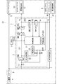
- FIG. 1 is a diagram showing a configuration of a drive system using the backup power supply system according to the embodiment.
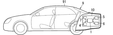
- FIG. 2 is a side view in which a part of the vehicle equipped with the backup power supply system of the above is broken.
- FIG. 3 is a flowchart showing an operation example 1 of the backup power supply system of the above.
- FIG. 4 is a time chart showing an operation example 2 of the backup power supply system of the above.
- FIG. 5 is a diagram showing a configuration of a backup power supply system according to the first modification of the embodiment.
- the backup power supply system 1 is mounted on the vehicle 9 (see FIG. 2), for example, and is used to supply electric power to the load when the main power supply 4 provided in the vehicle 9 fails. That is, the backup power supply system 1 is mounted on the vehicle 9 having the main power supply 4 and the load.
- the term "when the main power supply 4 fails" as used in the present disclosure means that the power supply from the main power supply 4 to the load or the like is stopped due to a failure, deterioration, disconnection, or the like of the main power supply 4.
- the vehicle 9 includes a drive system 10 and a vehicle body (vehicle body) 91 (see FIG. 2) on which the drive system 10 is mounted.
- the drive system 10 includes a backup power supply system 1, a main power supply 4, a plurality of loads (for example, a first load 5 and a second load 6), and an ECU (Electronic Control Unit) 7.
- the main power source 4 is, for example, a battery mounted on a vehicle 9 (a lead storage battery as an example), and is configured to supply electric power to a plurality of loads.
- the ECU 7 is configured to control a plurality of loads provided on the vehicle 9.
- the first load 5 is, for example, a brake system (hereinafter, also referred to as “brake system 5”).
- the second load 6 is, for example, a shift-by-wire system (hereinafter, also referred to as “shift-by-wire system 6”).
- shift-by-wire system 6 is referred to as the "SBW system 6".
- the brake system 5 is a system that electrically operates the brake mechanism provided on each wheel of the vehicle 9.
- the brake system 5 includes a drive control unit 51 and an actuator 52.
- the drive control unit 51 controls the drive of the actuator 52 by outputting a control signal to the actuator 52 based on the amount of operation of the brake pedal by the driver.
- the actuator 52 is configured to operate a braking mechanism provided on each wheel to apply a brake to each wheel in response to a control signal from the drive control unit 51.
- the shift-by-wire system 6 is a system that electrically switches the shift range of the automatic transmission mounted on the vehicle 9.
- the shift-by-wire system 6 includes a drive control unit 61 and an actuator 62.
- the drive control unit 61 controls the drive of the actuator 62 by outputting a control signal to the actuator 62 based on the position of the shift lever operated by the driver.
- the actuator 62 is configured to switch the shift range of the automatic transmission in response to a control signal from the drive control unit 61.
- the shift range of the automatic transmission includes a parking range (P range), a reverse range (R range), a neutral range (N range), and a drive range (D range).
- the drive range is used when the vehicle 9 is moving forward
- the reverse range is used when the vehicle 9 is moving backward
- the parking range is used when the vehicle 9 is parked.
- the actuator 62 locks the rotating shaft in the automatic transmission to lock the movement of the vehicle 9.
- the brake system 5 and the shift-by-wire system 6 are configured to operate by the electric power supplied from the main power supply 4 or the backup power supply system 1.
- the main power supply 4 When the main power supply 4 is normal, power is supplied from the main power supply 4 to the first load 5 and the second load 6 (that is, the brake system 5 and the shift-by-wire system 6). On the other hand, when the main power supply 4 fails, power is supplied from the backup power supply system 1 to the first load 5 and the second load 6. Therefore, even when the main power supply 4 fails, the first load 5 and the second load 6 can operate according to the operation of the driver.
- the backup power supply system 1 includes a first auxiliary power supply 22 and a second auxiliary power supply 3.
- Each of the first auxiliary power source 22 and the second auxiliary power source 3 is an auxiliary power source capable of supplying electric power to the first load (load) 5 when the main power source 4 fails.
- the second time is shorter than the first time.
- the first time is the time until the first auxiliary power supply 22 becomes able to supply electric power to the first load 5.
- the second time is the time until the second auxiliary power supply 3 becomes able to supply electric power to the first load 5. That is, the first time corresponds to the charging time of the first auxiliary power source 22, and the second time corresponds to the charging time of the second auxiliary power source 3.
- the first time and the second time are relative times, respectively.
- the second time corresponding to the charging time of the second auxiliary power supply 3 is shorter than the first time corresponding to the charging time of the first auxiliary power supply 22. Therefore, the charging of the second auxiliary power supply 3 can be completed before the first auxiliary power supply 22. Therefore, power can be supplied to the first load 5 by the second auxiliary power source 3 even during the period until the first time elapses. Therefore, compared to the case where the power is supplied to the first load 5 only by the first auxiliary power supply 22 when the main power supply 4 fails, the power is not supplied to the first load 5 when the main power supply 4 fails. It has the advantage of being less likely to be in a state.
- the backup power supply system 1 includes a backup power supply device 2 and a second auxiliary power supply 3.
- the backup power supply device 2 includes a control circuit 21, a first auxiliary power supply 22, a power supply circuit 23, a drive circuit 24, a plurality of switches SW1 to SW5 (five in FIG. 1), and a plurality of switches SW1 to SW5 (four in FIG. 1). )
- the diodes D1 to D4 are provided.
- the backup power supply device 2 further includes a plurality of input terminals T1 and T2 (two in FIG. 1) and one output terminal T3. That is, in the backup power supply system 1 according to the present embodiment, the first auxiliary power supply 22 and the second auxiliary power supply 3 are separately provided.
- the input terminal T1 is connected to the main power supply 4 via the ignition switch 8.
- the input terminal T1 is a terminal for inputting the power supplied from the main power supply 4 to the backup power supply device 2 when the ignition switch 8 is on.
- the input terminal T2 is connected to the second auxiliary power supply 3.
- the input terminal T2 is a terminal for inputting the power supplied from the second auxiliary power supply 3 to the backup power supply device 2.
- the output terminal T3 is connected to the brake system 5.
- the output terminal T3 is a terminal for outputting the electric power supplied from the first auxiliary power source 22 or the second auxiliary power source 3 to the brake system 5.
- main power supply 4 is connected to the brake system 5 via the ignition switch 8. Therefore, in the brake system 5, when the main power supply 4 is normal and the ignition switch 8 is on, power is also supplied from the main power supply 4.
- control circuit 21 is composed of, for example, a microcomputer having a processor and a memory. That is, the control circuit 21 is realized in a computer system having a processor and a memory. Then, when the processor executes an appropriate program, the computer system functions as the control circuit 21.
- the program may be pre-recorded in a memory, may be recorded through a telecommunication line such as the Internet, or may be recorded and provided on a non-temporary recording medium such as a memory card.
- the control circuit 21 controls at least the drive circuit 24. Specifically, the control circuit 21 outputs the first to fifth control signals for controlling the on / off of the switches SW1 to SW5 to the drive circuit 24.
- the drive circuit 24 controls the on / off of the switches SW1 to SW5 according to the first to fifth control signals from the control circuit 21.
- control circuit 21 has a failure diagnosis function related to the second auxiliary power supply 3.
- control circuit 21 has a first function and a second function.
- the first function is a function of determining whether or not the second auxiliary power supply 3 is normal.
- the second function is a function of determining whether or not the switches SW3 and SW4 provided in the second power supply path 102 from the second auxiliary power supply 3 to the brake system 5 are normal.
- the control circuit 21 measures the voltage at the first midpoint P1 between the input terminal T2 to which the second auxiliary power supply 3 is connected and the switch SW4. The control circuit 21 determines that the second auxiliary power supply 3 is normal if the voltage at the first midpoint P1 is equal to or higher than the first voltage, and if the voltage at the first midpoint P1 is smaller than the first voltage, the second auxiliary power supply 3 is second. It is determined that the auxiliary power supply 3 is abnormal.
- control circuit 21 detects a short circuit (short circuit) and an open (open) of the switches SW3 and SW4 by measuring the voltage of the second midpoint P2 between the switch SW3 and the switch SW4.
- the first auxiliary power supply 22 and the second auxiliary power supply 3 are backup (that is, auxiliary or spare) power supplies for the main power supply 4.
- the first auxiliary power source 22 and the second auxiliary power source 3 are auxiliary power sources capable of supplying electric power to the first load 5 when the main power source 4 fails.
- Each of the first auxiliary power supply 22 and the second auxiliary power supply 3 is, for example, an electric double layer capacitor (EDLC: Electric Double Layer Capacitor).
- EDLC Electric Double Layer Capacitor
- Each of the first auxiliary power source 22 and the second auxiliary power source 3 may be a secondary battery such as a lithium ion capacitor (LIC: Lithium Ion Capacitor) or a lithium ion battery (LIB: Lithium Ion Battery).
- a positive electrode is formed of a material similar to EDLC (for example, activated carbon), and a negative electrode is formed of a material similar to LIB (for example, a carbon material such as graphite).
- each of the first auxiliary power supply 22 and the second auxiliary power supply 3 is not limited to the electric double layer capacitor, and may be, for example, an electrochemical device having the configuration described below.
- the electrochemical device referred to here includes a positive electrode member, a negative electrode member, and a non-aqueous electrolytic solution.
- the positive electrode member includes a positive electrode current collector and a positive electrode material layer supported on the positive electrode current collector and containing a positive electrode active material.
- the positive electrode material layer contains a conductive polymer as a positive electrode active material that is doped and dedoped with anions (dopants).
- the negative electrode member has a negative electrode material layer containing a negative electrode active material.
- the negative electrode active material is, for example, a substance in which a redox reaction accompanied by occlusion and release of lithium ions proceeds, and specifically, a carbon material, a metal compound, an alloy, a ceramic material, or the like.
- the non-aqueous electrolyte solution has lithium ion conductivity as an example.
- This type of non-aqueous electrolyte contains a lithium salt and a non-aqueous solution that dissolves the lithium salt.
- An electrochemical device having such a configuration has a higher energy density than an electric double layer capacitor or the like.
- each of the first auxiliary power supply 22 and the second auxiliary power supply 3 is composed of two or more power storage devices (for example, an electric double layer capacitor) electrically connected in parallel, in series, or in parallel and in series. May be. That is, one first auxiliary power supply 22 and one second auxiliary power supply 3 may be realized by a parallel circuit or a series circuit of two or more power storage devices, or a combination thereof.
- the capacitance of the second auxiliary power supply 3 is smaller than the capacitance of the first auxiliary power supply 22. Therefore, when the first auxiliary power supply 22 and the second auxiliary power supply 3 are charged at the same time, the second time, which is the charging time of the second auxiliary power supply 3, is larger than the first time, which is the charging time of the first auxiliary power supply 22. Will also be shorter. In other words, during the second time until the second auxiliary power supply 3 can supply power to the first load 5, the first auxiliary power supply 22 can supply power to the first load 5. It is shorter than the first time to become.
- the second auxiliary power supply 3 is configured to supply power to both the first load 5 and the second load 6. Therefore, the second auxiliary power source 3 has a (electrostatic) capacity capable of supplying electric power to both the first load 5 and the second load 6.
- the first auxiliary power supply 22 and the second auxiliary power supply 3 are charged by the electric power supplied from the main power supply 4. Specifically, when the ignition switch 8 is turned on and the switch SW5 is turned on, the first auxiliary power source 22 is supplied with electric power from the main power source 4 and is charged by this electric power. Further, when the ignition switch 8 is turned on, the second auxiliary power source 3 is supplied with electric power from the main power source 4 and is charged by this electric power. Further, the first auxiliary power supply 22 and the second auxiliary power supply 3 are configured to discharge when the ignition switch 8 is turned off. Therefore, when the ignition switch 8 is turned on again, the first auxiliary power supply 22 and the second auxiliary power supply 3 are in an uncharged state.
- the "uncharged state" as used in the present disclosure means a fully charged state, that is, a state in which the remaining amount of electric energy is less than a state in which electric energy is sufficiently stored.
- the power supply circuit 23 is a circuit that generates an operating voltage of the control circuit 21.
- the power supply circuit 23 lowers the output voltage of the main power supply 4 input via the input terminals T1 and the diodes D1 and D3 to a predetermined voltage (for example, 5V) and outputs the output voltage to the control circuit 21. Further, the power supply circuit 23 lowers the output voltage of the first auxiliary power supply 22 input via the diode D2 to a predetermined voltage (for example, 5V) and outputs the output voltage to the control circuit 21. Further, the power supply circuit 23 lowers the output voltage of the second auxiliary power supply 3 input via the diode D4 to a predetermined voltage (for example, 5V) and outputs the output voltage to the control circuit 21.
- the control circuit 21 can be operated by the output power of the power supply circuit 23.
- the drive circuit 24 is configured to control a plurality of switches SW1 to SW5 separately. Specifically, the drive circuit 24 creates first to fifth drive signals for turning on / off the switches SW1 to SW5 according to the first to fifth control signals from the control circuit 21, and the created first first. The fifth drive signal is output to the switches SW1 to SW5. The switches SW1 to SW5 are turned on / off according to the first to fifth drive signals from the drive circuit 24.
- Each of the plurality of switches SW1 to SW5 is, for example, an enhancement type P-channel MOSFET (Metal Oxide Semiconductor Field Effect Transistor).
- the plurality of switches SW1 to SW5 are turned on / off according to the first to fifth drive signals output from the drive circuit 24.
- the switches SW1 and SW2 are provided between the first auxiliary power supply 22 and the output terminal T3 in the first power supply path 101 connecting the input terminal T1 and the output terminal T3.
- the switches SW1 and SW2 are connected in series with each other in the first power supply path 101.
- the source of the switch SW1 is connected to the first auxiliary power supply 22, and the drain of the switch SW1 is connected to the drain of the switch SW2. Further, the source of the switch SW2 is connected to the output terminal T3. Then, by turning on the switches SW1 and SW2 together, the electric power stored in the first auxiliary power source 22 can be supplied to the brake system 5 via the switches SW1 and SW2.
- the switches SW3 and SW4 are provided in the second power supply path 102 connecting the input terminal T2 and the output terminal T3.
- the switches SW3 and SW4 are connected in series with each other in the second power supply path 102.
- the source of the switch SW4 is connected to the input terminal T2, and the drain of the switch SW4 is connected to the drain of the switch SW3. Further, the source of the switch SW3 is connected to the output terminal T3. Then, by turning on the switches SW3 and SW4 together, the electric power stored in the second auxiliary power source 3 can be supplied to the brake system 5 via the switches SW3 and SW4.
- the backup power supply system 1 is configured to supply power to the brake system 5 from one of the auxiliary power supplies 22 of the first auxiliary power supply 22 and the second auxiliary power supply 3. Therefore, when the switches SW1 and SW2 are turned on to supply power to the brake system 5 from the first auxiliary power supply 22, the switches SW3 and SW4 are turned off to stop the power supply from the second auxiliary power supply 3. There is. When the switches SW3 and SW4 are turned on to supply power to the brake system 5 from the second auxiliary power supply 3, the switches SW1 and SW2 are turned off to stop the power supply from the first auxiliary power supply 22. There is.
- the switching circuit 25 is configured by the switches SW1 to SW4 and the drive circuit 24. That is, in the backup power supply system 1 according to the present embodiment, the first auxiliary power supply 22 supplies power to the first load 5 and the second auxiliary power supply 3 supplies power to the first load 5. A switching circuit 25 for switching between states is further provided.
- the switch SW5 is provided between the input terminal T1 and the first auxiliary power supply 22 in the first power supply path 101 connecting the input terminal T1 and the output terminal T3.
- the source of the switch SW5 is connected to the input terminal T1 via the diode D1, and the drain of the switch SW5 is connected to the first auxiliary power supply 22.
- the first auxiliary power supply 22 can be charged by turning on the ignition switch 8 and the switch SW5. Therefore, even if the ignition switch 8 is on, if the switch SW5 is off, the first auxiliary power supply 22 is not charged.
- the diode D1 is provided between the input terminal T1 and the switch SW5 in the first power supply path 101 connecting the input terminal T1 and the output terminal T3.
- the anode of the diode D1 is connected to the input terminal T1, and the cathode of the diode D1 is connected to the source of the switch SW5.
- the diode D2 is provided between the first auxiliary power supply 22 and the power supply circuit 23.
- the anode of the diode D2 is connected to the first auxiliary power supply 22, and the cathode of the diode D2 is connected to the power supply circuit 23.
- the diode D3 is provided between the connection point of the diode D1 and the switch SW5 and the power supply circuit 23.
- the anode of the diode D3 is connected to the connection point of the diode D1 and the switch SW5, and the cathode of the diode D3 is connected to the power supply circuit 23.
- the diode D4 is provided between the input terminal T2 and the power supply circuit 23.
- the anode of the diode D4 is connected to the input terminal T2, and the cathode of the diode D4 is connected to the power supply circuit 23.
- the diodes D1 and D3 are conductive and the diodes D2 and D4 are non-conducting, so that the main power supply 4
- the output voltage of is input to the power supply circuit 23 via the diodes D1 and D3.
- the power supply circuit 23 lowers the input output voltage of the main power supply 4 to a predetermined voltage (for example, 5V) and outputs it to the control circuit 21.
- the diodes D2 are conductive and the diodes D1, D3, and D4 are non-conducting, so that the first auxiliary power supply is not conducted.
- the output voltage of 22 is input to the power supply circuit 23 via the diode D2. Then, the power supply circuit 23 lowers the input output voltage of the first auxiliary power supply 22 to a predetermined voltage (for example, 5V) and outputs it to the control circuit 21.
- the diodes D4 are conductive and the diodes D1, D2, D3 are non-conducting, so that the second auxiliary power supply is not conducted.
- the output voltage of 3 is input to the power supply circuit 23 via the diode D4. Then, the power supply circuit 23 lowers the input output voltage of the second auxiliary power supply 3 to a predetermined voltage (for example, 5V) and outputs it to the control circuit 21.
- step S1 When the main power supply 4 has not failed, that is, when the main power supply 4 is normal (step S1: No), power is supplied from the main power supply 4 to the first load 5 (step S2).
- the control circuit 21 is configured so that it can be determined whether or not the main power supply 4 has failed by measuring the output voltage of the main power supply 4, for example.
- step S3: Yes When the main power supply 4 has failed (step S1: Yes), has the first time passed since the control circuit 21 started charging the first auxiliary power supply 22 and the second auxiliary power supply 3? Whether or not it is determined (step S3).
- step S3: Yes When the first time has elapsed (step S3: Yes), the control circuit 21 turns on the switches SW1 and SW2 and turns off the switches SW3 and SW4 to turn off the first auxiliary power source 22 to the first load 5. Is supplied with electric power (step S4).
- step S5 On the other hand, when the first time has not elapsed (step S3: No), the control circuit 21 determines whether or not the second time has elapsed (step S5). In this case, since the first time has not elapsed, the first auxiliary power source 22 is not charged until the first load 5 can be supplied with electric power.
- step S5 When the second time has elapsed (step S5: Yes), the control circuit 21 turns on the switches SW3 and SW4 and turns off the switches SW1 and SW2 to turn off the second auxiliary power source 3 to the first load 5. Is supplied with electric power (step S6). On the other hand, when the second time has not elapsed (step S5: No), the control circuit 21 turns off the switches SW1 to SW4 to supply power from both the first auxiliary power supply 22 and the second auxiliary power supply 3. Do not supply.
- the first auxiliary power source 22 Power may be supplied to the first load 5. Further, if the second time has passed while the main power supply 4 is supplying power to the first load 5, the second auxiliary power supply 3 is added to the power supply from the main power supply 4 to the first load 5. Power may be supplied to the first load 5.
- the first auxiliary power supply 22 becomes the first load 5 during the second time until the second auxiliary power supply 3 can supply power to the first load 5.
- power is not supplied to the first load 5 when the main power supply 4 fails, as compared with the case where power is supplied to the first load 5 only by the first auxiliary power supply 22 when the main power supply 4 fails.
- the vehicle 9 traveling at a speed of several km is stopped by the brake system 5, so that the vehicle 9 traveling at a speed of several tens of km is stopped as compared with the case where the vehicle 9 is stopped.
- the power consumption of the brake system 5 is small. Therefore, in remote parking, the vehicle 9 can be stopped even with the second auxiliary power supply 3 having a smaller capacitance than the first auxiliary power supply 22.
- the vehicle 9 running at a speed of several tens of kilometers is stopped, power is supplied to the brake system 5 from the first auxiliary power source 22 having a larger capacitance than the second auxiliary power source 3.
- the second auxiliary power supply 3 has a first load 5 rather than a first state in which the first auxiliary power supply 22 supplies power to the first load (brake system) 5. Power is supplied to the first load 5 in the second state where the power consumption of the first load is small.
- the user (driver or passenger) of the vehicle 9 gives an instruction for remote parking to the ECU 7 of the vehicle 9 using, for example, a dedicated remote controller.
- the ignition switch 8 is off. Therefore, in this case, power is not supplied from the main power source 4 to the first auxiliary power source 22 and the second auxiliary power source 3, and the first auxiliary power source 22 and the second auxiliary power source 3 are not charged. Further, when the ignition switch 8 is off, the electric power stored in the first auxiliary power supply 22 and the second auxiliary power supply 3 is discharged, so that the first auxiliary power supply 22 and the second auxiliary power supply 3 are in an uncharged state. is there.
- the ECU 7 When the remote parking instruction is given to the ECU 7, the ECU 7 turns on the ignition switch 8 and starts charging the second auxiliary power source 3.
- the ignition switch 8 When the ignition switch 8 is turned on, power is supplied from the main power supply 4 to the power supply circuit 23, and the control circuit 21 is activated by the output power of the power supply circuit 23.
- the permission flag F3 is turned off, and remote parking cannot be performed.
- all of the switches SW1 to SW5 are off.
- the first auxiliary power source 22 is not charged, and only the second auxiliary power source 3 is charged. That is, the second auxiliary power source 3 is charged with priority over the first auxiliary power source 22 by the electric power supplied from the main power source 4.
- the ECU 7 outputs a request signal (specific signal) Sig1 requesting the execution of remote parking to the control circuit 21.
- the control circuit 21 executes various processes shown below in order to perform remote parking.
- the ECU 7 of the vehicle 9 is an external system.
- the control circuit 21 detects a short circuit (short circuit) of the switches SW2 and SW3 before the time t1. At this time, the control circuit 21 detects a short circuit of the switch SW2 by measuring the voltage at the third midpoint between the switches SW1 and SW2 while the switches SW1 to SW4 are off, and detects a short circuit between the switches SW3 and SW4. A short circuit of the switch SW3 is detected by measuring the voltage at the midpoint P2. Further, the control circuit 21 turns on the switch SW3 at time t1 and measures the voltage between the switches SW3 and SW4 to detect the opening of the switch SW3. The control circuit 21 turns off the switch SW3 at the time t2.
- the control circuit 21 turns on the request flag F2 at time t2 if the switch SW3 is not short-circuited and is not open.
- the control circuit 21 measures the voltage at the first midpoint P1, and if this voltage is equal to or higher than the first voltage, it determines that power is being output from the second auxiliary power supply 3. Then, the control circuit 21 turns on the output flag F1 (see FIG. 4). At this time, since the switches SW3 and SW4 are off, the output power of the second auxiliary power supply 3 is supplied to the shift-by-wire system 6, but not to the brake system 5.
- the control circuit 21 detects a short circuit of the switch SW4 in the period from time t2 to time t3.
- the control circuit 21 detects a short circuit of the switch SW4 by measuring the voltage of the second midpoint P2 between the switches SW3 and SW4 while the switches SW3 and SW4 are off. If the switch SW4 is not short-circuited, the control circuit 21 detects the opening of the switch SW4 by turning on the switch SW4. The control circuit 21 detects the opening of the switch SW4 by measuring the voltage of the second midpoint P2 between the switches SW3 and SW4.
- the control circuit 21 turns on the switch SW3 at time t4 if the switch SW4 is not short-circuited and is not open. At this time, the control circuit 21 turns off the request flag F2. At this time, since the switches SW3 and SW4 are both turned on, the output power of the second auxiliary power source 3 is supplied to both the brake system 5 and the shift-by-wire system 6.
- the permission flag F3 is turned on because the second auxiliary power source 3 is in a state where power can be supplied to the brake system (first load) 5 and remote parking is possible.
- an authorization signal is output to the ECU 7.
- the ECU 7 Upon receiving the permission signal from the control circuit 21, the ECU 7 transmits an operable signal indicating that remote parking is possible to the remote controller. Remote parking is started when the user performs a specific operation (operation for performing remote parking) on the remote controller that has received the operable signal.
- the control circuit 21 turns on the charge permission flag F5 and turns on the switch SW5 to start charging the first auxiliary power source 22.
- the control circuit 21 turns off the output flag F1 because the output voltage of the second auxiliary power supply 3 is equal to or lower than the first voltage at time t6.
- the control circuit 21 turns off the permission flag F3 because the output voltage of the second auxiliary power supply 3 is equal to or lower than the first voltage and is not in a state where power can be supplied to the brake system 5.
- the control circuit 21 turns on the prohibition flag F4 when the permission flag F3 is turned from on to off at the time t8.
- the control circuit 21 turns off the switches SW3 and SW4 at time t9, and stops the power supply from the second auxiliary power source 3 to the brake system 5.
- the control circuit 21 detects a short circuit of the switch SW1 in the period from time t9 to time t10.
- the control circuit 21 detects a short circuit of the switch SW1 by measuring the voltage at the third midpoint between the switches SW1 and SW2 while the switches SW1 and SW2 are off.
- the control circuit 21 detects that the switches SW1 and SW2 are open if the switches SW1 and SW2 are not short-circuited.
- the control circuit 21 turns on the switches SW1 and SW2 at time t10 and measures the voltage at the third midpoint between the switches SW1 and SW2 to detect the opening of the switches SW1 and SW2.
- the control circuit 21 turns off the switches SW1 and SW2 and turns on the switches SW3 and SW4 at time t11. Then, at time t12, the control circuit 21 outputs because the output voltage of the second auxiliary power supply 3 is equal to or higher than the first voltage and is in a state where power can be supplied to the brake system 5.
- the flag F1 is turned on and the permission flag F3 is turned on.
- the control circuit 21 Since the first auxiliary power source 22 has been charged at time t13, the control circuit 21 turns off the switches SW3 and SW4 in order to stop the power supply from the second auxiliary power source 3 to the brake system 5. To do. As a result, the power supply from the second auxiliary power source 3 to the brake system 5 is stopped. Then, after time t13, since the first auxiliary power supply 22 is in a state where power can be supplied to the brake system 5, the control circuit 21 turns on the switches SW1 and SW2 to turn on the first auxiliary power supply 22. Power is supplied to the brake system 5.
- the first auxiliary power supply 22 becomes the first load 5 during the second time until the second auxiliary power supply 3 can supply power to the first load 5.
- power is not supplied to the first load 5 when the main power supply 4 fails, as compared with the case where power is supplied to the first load 5 only by the first auxiliary power supply 22 when the main power supply 4 fails.
- the first auxiliary power supply 22 and the second auxiliary power supply 3 are charged at the same time, as compared with the case where the second auxiliary power supply 3 is charged at the same time. , The charging time of the second auxiliary power supply 3 can be shortened.
- the second auxiliary power supply 3 when the control circuit 21 receives the request signal (specific signal) Sigma 1 input from the ECU 7 as an external system, the second auxiliary power supply 3 is the first load 5 If the power supply is possible, the second auxiliary power supply 3 is in the power supply capable state, that is, the above permission signal is output to the ECU 7.
- the second auxiliary power source 3 when the engine of the vehicle 9 is started before instructing remote parking with the remote controller, the second auxiliary power source 3 is used during the period from the start of the engine of the vehicle 9 to the instruction of remote parking. Can be charged. Therefore, the power supply to the first load 5 can be started at an earlier timing than in the case where the second auxiliary power supply 3 can be supplied with power after receiving the request signal Sigma 1 from the ECU 7.
- the "power supply enable state" referred to in the present disclosure means that the second auxiliary power supply 3 is charged and can supply power from the second auxiliary power supply 3 to the first load 5, and that the second auxiliary power supply 3 is normal and the switch SW3 is used. , SW4 is normal (the second power supply path 102 from the second auxiliary power source 3 to the first load 5 is normal).
- the above-described embodiment is only one of the various embodiments of the present disclosure.
- the above-described embodiment can be changed in various ways depending on the design and the like as long as the object of the present disclosure can be achieved.
- the same function as the backup power supply system 1 according to the above-described embodiment may be realized by a power supply backup method, a computer program, a non-temporary recording medium on which the computer program is recorded, or the like.
- the power supply backup method is the power supply backup method used for the backup power supply system 1.
- the backup power supply system 1 includes a first auxiliary power supply 22 and a second auxiliary power supply 3 capable of supplying power to the first load (load) 5 when the main power supply 4 fails.
- the second time is shorter than the first time.
- the first time is the time until the first auxiliary power supply 22 becomes able to supply electric power to the first load 5.
- the second time is the time until the second auxiliary power supply 3 becomes able to supply electric power to the first load 5.
- the program according to one aspect is a program for causing one or more processors to execute the above-mentioned power supply backup method.
- the control circuit 21 includes a computer system.
- a computer system mainly consists of a processor and a memory as hardware.
- the program may be pre-recorded in the memory of the computer system, may be provided through a telecommunications line, and may be recorded on a non-temporary recording medium such as a memory card, optical disk, hard disk drive, etc. that can be read by the computer system. May be provided.
- a processor in a computer system is composed of one or more electronic circuits including a semiconductor integrated circuit (IC) or a large scale integrated circuit (LSI).
- the integrated circuit such as IC or LSI referred to here has a different name depending on the degree of integration, and includes an integrated circuit called a system LSI, VLSI (Very Large Scale Integration), or ULSI (Ultra Large Scale Integration).
- an FPGA Field-Programmable Gate Array
- a plurality of electronic circuits may be integrated on one chip, or may be distributed on a plurality of chips.
- the plurality of chips may be integrated in one device, or may be distributed in a plurality of devices.
- the computer system referred to here includes a microprocessor having one or more processors and one or more memories. Therefore, the microprocessor is also composed of one or a plurality of electronic circuits including a semiconductor integrated circuit or a large-scale integrated circuit.
- the backup power supply system 1 it is not an essential configuration for the backup power supply system 1 that a plurality of functions in the backup power supply system 1 are integrated in one housing. That is, the components of the backup power supply system 1 may be distributed in a plurality of housings. Further, at least a part of the functions of the backup power supply system 1, for example, the functions of the control circuit 21 may be realized by the cloud (cloud computing) or the like.
- the backup power supply system 1A according to the first modification includes the backup power supply device 2A.
- the backup power supply device 2A includes a control circuit 21, a first auxiliary power supply 22A, a power supply circuit 23, a drive circuit 24, a plurality of switches SW1 to SW5 (five in FIG. 5), and a plurality of switches SW1 to SW5 (four in FIG. 5). )
- the diodes D1 to D4 are provided.
- the backup power supply device 2A further includes a plurality of input terminals T1 and T2 (two in FIG. 5) and one output terminal T3.
- the configurations other than the first auxiliary power supply 22A are the same as those of the backup power supply system 1 according to the above-described embodiment, and the description thereof will be omitted here.
- the first auxiliary power supply 22A has, for example, a series circuit in which five electric double layer capacitors are connected in series between the first power supply path 101 and the ground.
- the second auxiliary power supply 3A is made up of the electric double layer capacitors that are connected to the position closest to the ground. That is, in the backup power supply system 1A according to the first modification, the first auxiliary power supply 22A includes the second auxiliary power supply 3A.
- the electric double layer capacitor connected to the position closest to the ground is charged in order among the five electric double layer capacitors, so that the second auxiliary power supply 3A is preferentially charged. be able to.
- the backup power supply system 1A according to the first modification is configured to preferentially charge the second auxiliary power supply 3A as described above. Therefore, even during the period until the first auxiliary power source 22A is charged, the second auxiliary power source 3A can supply electric power to the first load 5. Therefore, as compared with the case where the power is supplied to the first load 5 only by the first auxiliary power supply 22A when the main power supply 4 fails, the power is not supplied to the first load 5 when the main power supply 4 fails. It has the advantage of being difficult to become.
- the power supplied from the main power supply 4 is used to prioritize the charging of the second auxiliary power supply 3 over the first auxiliary power supply 22, but the first auxiliary power supply 22 and the second auxiliary power supply 3 are charged.
- charging may be performed at the same time. In this case, for example, by turning on the switch SW5 at the timing when the control circuit 21 is activated, the first auxiliary power supply 22 and the second auxiliary power supply 3 can be charged at the same time.
- the switching circuit 25 switches between a state in which power is supplied from the first auxiliary power supply 22 to the first load 5 and a state in which power is supplied from the second auxiliary power supply 3 to the first load 5. ..
- it may be configured to supply power to the first load 5 from both the first auxiliary power source 22 and the second auxiliary power source 3.
- the second load is the shift-by-wire system 6, but the second load is not limited to the shift-by-wire system 6, and may be, for example, a door lock system that locks the door of the vehicle 9.
- remote parking is performed using a remote controller
- remote parking may be performed using a smartphone, tablet, or the like that has downloaded a dedicated application.
- the control circuit 21 when the control circuit 21 receives the request signal Sigma 1 from the ECU 7, if the second auxiliary power supply 3 is in a power supply capable state, the ECU 7 is informed that the second auxiliary power supply 3 is in a power supply possible state. It is outputting.
- the second auxiliary power source 3 after receiving the request signal Sigma 1 from the ECU 7, the second auxiliary power source 3 may be set to a state in which electric power can be supplied to the first load 5. As a result, the second auxiliary power supply 3 can be made available for power supply by the request signal Sigma 1 from the ECU 7.
- the backup power supply system (1; 1A) is the first auxiliary power supply (22;) capable of supplying power to the load (5) when the main power supply (4) fails. 22A) and a second auxiliary power source (3; 3A).
- the second time is shorter than the first time.
- the first time is the time until the first auxiliary power source (22; 22A) becomes able to supply electric power to the load (5).
- the second time is the time until the second auxiliary power source (3; 3A) becomes able to supply electric power to the load (5).
- the second auxiliary power supply (3; 3A) supplies power to the load (5) until the first auxiliary power supply (22; 22A) can supply power to the load (5). It can supply power.
- the load (4) fails when the main power source (4) fails, as compared with the case where power is supplied to the load (5) only by the first auxiliary power source (22; 22A) when the main power source (4) fails.
- 5) has the advantage that it is unlikely that power will not be supplied.
- the first auxiliary power supply (22; 22A) and the second auxiliary power supply (3; 3A) are supplied from the main power supply (4). It is charged by the electric power generated.
- the first auxiliary power supply (22; 22A) and the second auxiliary power supply (3; 3A) can be charged by the electric power supplied from the main power supply (4).
- the capacity of the second auxiliary power supply (3; 3A) is larger than the capacity of the first auxiliary power supply (22; 22A). small.
- the second auxiliary power supply (22; 22A) takes less time than the first auxiliary power supply (22; 22A).
- the power supply (3; 3A) can be charged.
- the second auxiliary power supply (3; 3A) is the second by the electric power supplied from the main power supply (4). 1 It is charged with priority over the auxiliary power supply (22; 22A).
- the second auxiliary power supply (3; 3A) is charged in a shorter time than when the first auxiliary power supply (22; 22A) and the second auxiliary power supply (3; 3A) are charged at the same time. be able to.
- the first auxiliary power supply (22A) includes the second auxiliary power supply (3A).
- the backup power supply system (1; 1A) according to the sixth aspect is mounted on the vehicle (9) including the main power source (4) and the load (5) in any one of the first to fifth aspects.
- the second auxiliary power supply (3; 3A) is the first load (5) and the first load as a load. Power can be supplied to both the second load (6), which is different from the load (5).
- power can be supplied to both the first load (5) and the second load (6) when the main power supply (4) fails.
- the second auxiliary power supply (3; 3A) is applied to at least both the first load (5) and the second load (6).
- it has a capacity that can supply electric power.
- power can be supplied to both the first load (5) and the second load (6) when the main power supply (4) fails.
- the second auxiliary power source (3; 3A) supplies power to the load (5) in the second state. To do. In the second state, the power consumption of the load (5) is smaller than that in the first state in which the first auxiliary power supply (22; 22A) supplies power to the load (5).
- the load (5) in the second state, can be operated by the electric power supplied from the second auxiliary power source (3; 3A).
- the backup power supply system (1; 1A) according to the tenth aspect further includes a switching circuit (25) in any one of the first to ninth aspects.
- the switching circuit (25) the first auxiliary power supply (22; 22A) supplies power to the load (5), and the second auxiliary power supply (3; 3A) supplies power to the load (5). Switch between the supply state and the supply state.
- a state in which the first auxiliary power supply (22; 22A) supplies power to the load (5) and a state in which the second auxiliary power supply (3; 3A) supplies power to the load (5). Can be switched.
- the backup power supply system (1; 1A) receives a specific signal (Sigma1) from the external system (7) in any one of the first to tenth aspects, and the second auxiliary power supply (1; 1A). If 3; 3A) is in a power supply capable state, the fact that the second auxiliary power supply (3; 3A) is in a power supply capable state is output to the external system (13).
- the power supply available state is a state in which the second auxiliary power source (3; 3A) can supply power to the load (5).
- the load (5) is more affected. Power supply can be started at an early timing.
- the backup power supply system (1; 1A) in any one of the first to tenth aspects, after receiving the specific signal (Sigma1) input from the external system (7), the second auxiliary power supply (1; 1A) 3; 3A) is put into a state where power can be supplied to the load (5).
- the second auxiliary power supply (3; 3A) can be made available for power supply by the specific signal (Sigma1) input from the external system (7).
- the backup power supply system (1; 1A) according to the thirteenth aspect has a failure diagnosis function regarding the second auxiliary power supply (3; 3A) in any one of the first to twelfth aspects.
- a failure diagnosis regarding the second auxiliary power supply (3; 3A) can be performed.
- the power supply backup method is the power supply backup method used in the backup power supply system (1; 1A).
- the backup power supply system (1; 1A) is a first auxiliary power supply (22; 22A) and a second auxiliary power supply (3; 3A) capable of supplying power to the load (5) when the main power supply (4) fails.
- the second time is shorter than the first time.
- the first time is the time until the first auxiliary power source (22; 22A) becomes able to supply electric power to the load (5).
- the second time is the time until the second auxiliary power source (3; 3A) becomes able to supply electric power to the load (5).
- the second auxiliary power supply (3; 3A) supplies power to the load (5) until the first auxiliary power supply (22; 22A) can supply power to the load (5). It can supply power.
- the load (4) fails when the main power source (4) fails, as compared with the case where power is supplied to the load (5) only by the first auxiliary power source (22; 22A) when the main power source (4) fails.
- 5) has the advantage that it is unlikely that power will not be supplied.
- the program according to the fifteenth aspect is a program for causing one or more processors to execute the power supply backup method according to the fourteenth aspect.
- the second auxiliary power supply (3; 3A) supplies power to the load (5) until the first auxiliary power supply (22; 22A) can supply power to the load (5). It can supply power.
- the load (4) fails when the main power source (4) fails, as compared with the case where power is supplied to the load (5) only by the first auxiliary power source (22; 22A) when the main power source (4) fails.
- 5) has the advantage that it is unlikely that power will not be supplied.
- the configurations according to the second to thirteenth aspects are not essential configurations for the backup power supply system (1; 1A) and can be omitted as appropriate.
Landscapes
- Engineering & Computer Science (AREA)
- Power Engineering (AREA)
- Mechanical Engineering (AREA)
- Business, Economics & Management (AREA)
- Emergency Management (AREA)
- Transportation (AREA)
- Stand-By Power Supply Arrangements (AREA)
Abstract
La présente invention concerne un système d'alimentation électrique de secours (1) qui est pourvu d'une première alimentation électrique auxiliaire (22) et d'une seconde alimentation électrique auxiliaire (3) qui sont aptes à fournir de l'électricité à une première charge (5) lorsqu'une défaillance d'une alimentation électrique principale (4) s'est produite. Dans le système d'alimentation électrique de secours (1), un second temps est plus court qu'un premier temps. Le premier temps est le temps nécessaire jusqu'à ce que la première alimentation auxiliaire (22) puisse fournir de l'électricité à la première charge (5). Le second temps est le temps nécessaire jusqu'à ce que la seconde alimentation auxiliaire (3) puisse fournir de l'électricité à la première charge (5).
Priority Applications (3)
| Application Number | Priority Date | Filing Date | Title |
|---|---|---|---|
| CN202080065257.9A CN114514668A (zh) | 2019-09-27 | 2020-09-18 | 备用电源系统、电源备用方法以及程序 |
| US17/640,996 US11945384B2 (en) | 2019-09-27 | 2020-09-18 | Backup power supply system, power supply backup method, and program |
| JP2021548897A JPWO2021060220A1 (fr) | 2019-09-27 | 2020-09-18 |
Applications Claiming Priority (2)
| Application Number | Priority Date | Filing Date | Title |
|---|---|---|---|
| JP2019-178085 | 2019-09-27 | ||
| JP2019178085 | 2019-09-27 |
Publications (1)
| Publication Number | Publication Date |
|---|---|
| WO2021060220A1 true WO2021060220A1 (fr) | 2021-04-01 |
Family
ID=75164916
Family Applications (1)
| Application Number | Title | Priority Date | Filing Date |
|---|---|---|---|
| PCT/JP2020/035647 WO2021060220A1 (fr) | 2019-09-27 | 2020-09-18 | Système d'alimentation électrique de secours, procédé de secours d'alimentation électrique et programme |
Country Status (4)
| Country | Link |
|---|---|
| US (1) | US11945384B2 (fr) |
| JP (1) | JPWO2021060220A1 (fr) |
| CN (1) | CN114514668A (fr) |
| WO (1) | WO2021060220A1 (fr) |
Cited By (1)
| Publication number | Priority date | Publication date | Assignee | Title |
|---|---|---|---|---|
| WO2024024034A1 (fr) * | 2022-07-28 | 2024-02-01 | 株式会社オートネットワーク技術研究所 | Dispositif de commande de sauvegarde embarqué |
Citations (4)
| Publication number | Priority date | Publication date | Assignee | Title |
|---|---|---|---|---|
| JPH1084628A (ja) * | 1996-09-10 | 1998-03-31 | Chugoku Electric Power Co Inc:The | モータ駆動用電源装置 |
| JP2011030362A (ja) * | 2009-07-24 | 2011-02-10 | Toyota Industries Corp | 車両用電源装置 |
| JP2018191440A (ja) * | 2017-05-08 | 2018-11-29 | 株式会社オートネットワーク技術研究所 | 車両用電源制御装置、車両用電源装置、及び車両用電源制御装置の制御回路 |
| JP2018191513A (ja) * | 2012-12-24 | 2018-11-29 | マグナ クロージャーズ インコーポレイテッド | 自動車システムのためのバックアップエネルギ源及び関連の制御方法 |
Family Cites Families (4)
| Publication number | Priority date | Publication date | Assignee | Title |
|---|---|---|---|---|
| FR2805843B1 (fr) * | 2000-03-03 | 2003-09-12 | Valeo Securite Habitacle | Ensemble de verrouillage d'une porte de vehicule automobile et procede de test du bon fonctionnement d'un module de serrure de cet ensemble |
| CA2544337A1 (fr) * | 2003-11-13 | 2005-05-26 | Intier Automotive Closures Inc. | Verrou electrique dote d'un verrou embarque a microcontroleur et d'une energie d'appoint integree |
| US9722231B2 (en) * | 2013-09-06 | 2017-08-01 | Johnson Controls Technology Company | Bladed fuse connectors for use in a vehicle battery module |
| JP6733572B2 (ja) | 2017-02-13 | 2020-08-05 | トヨタ自動車株式会社 | 駐車支援装置 |
-
2020
- 2020-09-18 CN CN202080065257.9A patent/CN114514668A/zh active Pending
- 2020-09-18 WO PCT/JP2020/035647 patent/WO2021060220A1/fr active Application Filing
- 2020-09-18 JP JP2021548897A patent/JPWO2021060220A1/ja active Pending
- 2020-09-18 US US17/640,996 patent/US11945384B2/en active Active
Patent Citations (4)
| Publication number | Priority date | Publication date | Assignee | Title |
|---|---|---|---|---|
| JPH1084628A (ja) * | 1996-09-10 | 1998-03-31 | Chugoku Electric Power Co Inc:The | モータ駆動用電源装置 |
| JP2011030362A (ja) * | 2009-07-24 | 2011-02-10 | Toyota Industries Corp | 車両用電源装置 |
| JP2018191513A (ja) * | 2012-12-24 | 2018-11-29 | マグナ クロージャーズ インコーポレイテッド | 自動車システムのためのバックアップエネルギ源及び関連の制御方法 |
| JP2018191440A (ja) * | 2017-05-08 | 2018-11-29 | 株式会社オートネットワーク技術研究所 | 車両用電源制御装置、車両用電源装置、及び車両用電源制御装置の制御回路 |
Cited By (1)
| Publication number | Priority date | Publication date | Assignee | Title |
|---|---|---|---|---|
| WO2024024034A1 (fr) * | 2022-07-28 | 2024-02-01 | 株式会社オートネットワーク技術研究所 | Dispositif de commande de sauvegarde embarqué |
Also Published As
| Publication number | Publication date |
|---|---|
| JPWO2021060220A1 (fr) | 2021-04-01 |
| CN114514668A (zh) | 2022-05-17 |
| US20220274551A1 (en) | 2022-09-01 |
| US11945384B2 (en) | 2024-04-02 |
Similar Documents
| Publication | Publication Date | Title |
|---|---|---|
| EP2982536B1 (fr) | Dispositif d'alimentation électrique | |
| JP6312597B2 (ja) | 車両用電源装置 | |
| JP6598542B2 (ja) | 電源装置および電源装置の制御方法 | |
| WO2014061137A1 (fr) | Système de gestion d'alimentation et procédé de gestion d'alimentation | |
| WO2022114197A1 (fr) | Système de source d'alimentation de secours et corps mobile | |
| WO2021060220A1 (fr) | Système d'alimentation électrique de secours, procédé de secours d'alimentation électrique et programme | |
| CN111002826A (zh) | 控制设备和控制方法 | |
| WO2018012302A1 (fr) | Dispositif d'alimentation électrique | |
| US11987191B2 (en) | Back-up power supply system and mobile body | |
| CN110832729A (zh) | 电源控制装置和电池单元 | |
| WO2021200774A1 (fr) | Système d'alimentation électrique de secours, procédé de secours d'alimentation électrique et programme | |
| WO2020166210A1 (fr) | Système d'alimentation électrique de secours pour shift-by-wire et programme de commande | |
| JP7021661B2 (ja) | 電源装置の制御装置 | |
| KR102263578B1 (ko) | 하이브리드 자동차의 듀얼 배터리 시스템 운영 방법 | |
| JP2022072398A (ja) | バックアップ電源システム、バックアップ電源システムの故障診断方法、及びプログラム | |
| JP2007104865A (ja) | 車両用電源システム | |
| JP2022093883A (ja) | 車載用のバックアップ制御装置及び車載用のバックアップ装置 | |
| JP2021164363A (ja) | 電源装置 | |
| WO2023182086A1 (fr) | Système de stockage d'énergie, procédé de commande de charge et programme | |
| US20190047494A1 (en) | Charging rate monitoring apparatus for in-vehicle power supply, and in-vehicle power supply system | |
| WO2024024034A1 (fr) | Dispositif de commande de sauvegarde embarqué | |
| JP5996386B2 (ja) | 充放電制御回路、車両用電源装置及び故障判定方法 | |
| US11643034B2 (en) | Vehicle power supply system and method for operating the same | |
| JP2023141347A (ja) | 車載補助電源システム、故障検知方法、及びプログラム | |
| WO2024004193A1 (fr) | Dispositif de commande de secours monté sur véhicule |
Legal Events
| Date | Code | Title | Description |
|---|---|---|---|
| 121 | Ep: the epo has been informed by wipo that ep was designated in this application |
Ref document number: 20869677 Country of ref document: EP Kind code of ref document: A1 |
|
| ENP | Entry into the national phase |
Ref document number: 2021548897 Country of ref document: JP Kind code of ref document: A |
|
| NENP | Non-entry into the national phase |
Ref country code: DE |
|
| 122 | Ep: pct application non-entry in european phase |
Ref document number: 20869677 Country of ref document: EP Kind code of ref document: A1 |