WO2021060220A1 - Backup power supply system, power supply backup method, and program - Google Patents
Backup power supply system, power supply backup method, and program Download PDFInfo
- Publication number
- WO2021060220A1 WO2021060220A1 PCT/JP2020/035647 JP2020035647W WO2021060220A1 WO 2021060220 A1 WO2021060220 A1 WO 2021060220A1 JP 2020035647 W JP2020035647 W JP 2020035647W WO 2021060220 A1 WO2021060220 A1 WO 2021060220A1
- Authority
- WO
- WIPO (PCT)
- Prior art keywords
- power supply
- auxiliary power
- load
- backup
- auxiliary
- Prior art date
Links
Images


Classifications
-
- H—ELECTRICITY
- H02—GENERATION; CONVERSION OR DISTRIBUTION OF ELECTRIC POWER
- H02J—CIRCUIT ARRANGEMENTS OR SYSTEMS FOR SUPPLYING OR DISTRIBUTING ELECTRIC POWER; SYSTEMS FOR STORING ELECTRIC ENERGY
- H02J7/00—Circuit arrangements for charging or depolarising batteries or for supplying loads from batteries
- H02J7/14—Circuit arrangements for charging or depolarising batteries or for supplying loads from batteries for charging batteries from dynamo-electric generators driven at varying speed, e.g. on vehicle
- H02J7/1423—Circuit arrangements for charging or depolarising batteries or for supplying loads from batteries for charging batteries from dynamo-electric generators driven at varying speed, e.g. on vehicle with multiple batteries
-
- B—PERFORMING OPERATIONS; TRANSPORTING
- B60—VEHICLES IN GENERAL
- B60R—VEHICLES, VEHICLE FITTINGS, OR VEHICLE PARTS, NOT OTHERWISE PROVIDED FOR
- B60R16/00—Electric or fluid circuits specially adapted for vehicles and not otherwise provided for; Arrangement of elements of electric or fluid circuits specially adapted for vehicles and not otherwise provided for
- B60R16/02—Electric or fluid circuits specially adapted for vehicles and not otherwise provided for; Arrangement of elements of electric or fluid circuits specially adapted for vehicles and not otherwise provided for electric constitutive elements
- B60R16/03—Electric or fluid circuits specially adapted for vehicles and not otherwise provided for; Arrangement of elements of electric or fluid circuits specially adapted for vehicles and not otherwise provided for electric constitutive elements for supply of electrical power to vehicle subsystems or for
- B60R16/033—Electric or fluid circuits specially adapted for vehicles and not otherwise provided for; Arrangement of elements of electric or fluid circuits specially adapted for vehicles and not otherwise provided for electric constitutive elements for supply of electrical power to vehicle subsystems or for characterised by the use of electrical cells or batteries
-
- B—PERFORMING OPERATIONS; TRANSPORTING
- B60—VEHICLES IN GENERAL
- B60T—VEHICLE BRAKE CONTROL SYSTEMS OR PARTS THEREOF; BRAKE CONTROL SYSTEMS OR PARTS THEREOF, IN GENERAL; ARRANGEMENT OF BRAKING ELEMENTS ON VEHICLES IN GENERAL; PORTABLE DEVICES FOR PREVENTING UNWANTED MOVEMENT OF VEHICLES; VEHICLE MODIFICATIONS TO FACILITATE COOLING OF BRAKES
- B60T13/00—Transmitting braking action from initiating means to ultimate brake actuator with power assistance or drive; Brake systems incorporating such transmitting means, e.g. air-pressure brake systems
- B60T13/74—Transmitting braking action from initiating means to ultimate brake actuator with power assistance or drive; Brake systems incorporating such transmitting means, e.g. air-pressure brake systems with electrical assistance or drive
-
- B—PERFORMING OPERATIONS; TRANSPORTING
- B60—VEHICLES IN GENERAL
- B60T—VEHICLE BRAKE CONTROL SYSTEMS OR PARTS THEREOF; BRAKE CONTROL SYSTEMS OR PARTS THEREOF, IN GENERAL; ARRANGEMENT OF BRAKING ELEMENTS ON VEHICLES IN GENERAL; PORTABLE DEVICES FOR PREVENTING UNWANTED MOVEMENT OF VEHICLES; VEHICLE MODIFICATIONS TO FACILITATE COOLING OF BRAKES
- B60T17/00—Component parts, details, or accessories of power brake systems not covered by groups B60T8/00, B60T13/00 or B60T15/00, or presenting other characteristic features
- B60T17/18—Safety devices; Monitoring
- B60T17/22—Devices for monitoring or checking brake systems; Signal devices
-
- H—ELECTRICITY
- H02—GENERATION; CONVERSION OR DISTRIBUTION OF ELECTRIC POWER
- H02J—CIRCUIT ARRANGEMENTS OR SYSTEMS FOR SUPPLYING OR DISTRIBUTING ELECTRIC POWER; SYSTEMS FOR STORING ELECTRIC ENERGY
- H02J7/00—Circuit arrangements for charging or depolarising batteries or for supplying loads from batteries
- H02J7/0013—Circuit arrangements for charging or depolarising batteries or for supplying loads from batteries acting upon several batteries simultaneously or sequentially
-
- H—ELECTRICITY
- H02—GENERATION; CONVERSION OR DISTRIBUTION OF ELECTRIC POWER
- H02J—CIRCUIT ARRANGEMENTS OR SYSTEMS FOR SUPPLYING OR DISTRIBUTING ELECTRIC POWER; SYSTEMS FOR STORING ELECTRIC ENERGY
- H02J7/00—Circuit arrangements for charging or depolarising batteries or for supplying loads from batteries
- H02J7/0063—Circuit arrangements for charging or depolarising batteries or for supplying loads from batteries with circuits adapted for supplying loads from the battery
-
- H—ELECTRICITY
- H02—GENERATION; CONVERSION OR DISTRIBUTION OF ELECTRIC POWER
- H02J—CIRCUIT ARRANGEMENTS OR SYSTEMS FOR SUPPLYING OR DISTRIBUTING ELECTRIC POWER; SYSTEMS FOR STORING ELECTRIC ENERGY
- H02J7/00—Circuit arrangements for charging or depolarising batteries or for supplying loads from batteries
- H02J7/34—Parallel operation in networks using both storage and other dc sources, e.g. providing buffering
-
- H—ELECTRICITY
- H02—GENERATION; CONVERSION OR DISTRIBUTION OF ELECTRIC POWER
- H02J—CIRCUIT ARRANGEMENTS OR SYSTEMS FOR SUPPLYING OR DISTRIBUTING ELECTRIC POWER; SYSTEMS FOR STORING ELECTRIC ENERGY
- H02J9/00—Circuit arrangements for emergency or stand-by power supply, e.g. for emergency lighting
- H02J9/04—Circuit arrangements for emergency or stand-by power supply, e.g. for emergency lighting in which the distribution system is disconnected from the normal source and connected to a standby source
- H02J9/06—Circuit arrangements for emergency or stand-by power supply, e.g. for emergency lighting in which the distribution system is disconnected from the normal source and connected to a standby source with automatic change-over, e.g. UPS systems
- H02J9/061—Circuit arrangements for emergency or stand-by power supply, e.g. for emergency lighting in which the distribution system is disconnected from the normal source and connected to a standby source with automatic change-over, e.g. UPS systems for DC powered loads
-
- B—PERFORMING OPERATIONS; TRANSPORTING
- B60—VEHICLES IN GENERAL
- B60T—VEHICLE BRAKE CONTROL SYSTEMS OR PARTS THEREOF; BRAKE CONTROL SYSTEMS OR PARTS THEREOF, IN GENERAL; ARRANGEMENT OF BRAKING ELEMENTS ON VEHICLES IN GENERAL; PORTABLE DEVICES FOR PREVENTING UNWANTED MOVEMENT OF VEHICLES; VEHICLE MODIFICATIONS TO FACILITATE COOLING OF BRAKES
- B60T2270/00—Further aspects of brake control systems not otherwise provided for
- B60T2270/40—Failsafe aspects of brake control systems
- B60T2270/406—Test-mode; Self-diagnosis
-
- B—PERFORMING OPERATIONS; TRANSPORTING
- B60—VEHICLES IN GENERAL
- B60T—VEHICLE BRAKE CONTROL SYSTEMS OR PARTS THEREOF; BRAKE CONTROL SYSTEMS OR PARTS THEREOF, IN GENERAL; ARRANGEMENT OF BRAKING ELEMENTS ON VEHICLES IN GENERAL; PORTABLE DEVICES FOR PREVENTING UNWANTED MOVEMENT OF VEHICLES; VEHICLE MODIFICATIONS TO FACILITATE COOLING OF BRAKES
- B60T2270/00—Further aspects of brake control systems not otherwise provided for
- B60T2270/40—Failsafe aspects of brake control systems
- B60T2270/414—Power supply failure
-
- F—MECHANICAL ENGINEERING; LIGHTING; HEATING; WEAPONS; BLASTING
- F16—ENGINEERING ELEMENTS AND UNITS; GENERAL MEASURES FOR PRODUCING AND MAINTAINING EFFECTIVE FUNCTIONING OF MACHINES OR INSTALLATIONS; THERMAL INSULATION IN GENERAL
- F16H—GEARING
- F16H61/00—Control functions within control units of change-speed- or reversing-gearings for conveying rotary motion ; Control of exclusively fluid gearing, friction gearing, gearings with endless flexible members or other particular types of gearing
- F16H2061/005—Supply of electric power, e.g. batteries for back up supply
-
- F—MECHANICAL ENGINEERING; LIGHTING; HEATING; WEAPONS; BLASTING
- F16—ENGINEERING ELEMENTS AND UNITS; GENERAL MEASURES FOR PRODUCING AND MAINTAINING EFFECTIVE FUNCTIONING OF MACHINES OR INSTALLATIONS; THERMAL INSULATION IN GENERAL
- F16H—GEARING
- F16H61/00—Control functions within control units of change-speed- or reversing-gearings for conveying rotary motion ; Control of exclusively fluid gearing, friction gearing, gearings with endless flexible members or other particular types of gearing
- F16H61/12—Detecting malfunction or potential malfunction, e.g. fail safe; Circumventing or fixing failures
- F16H2061/1256—Detecting malfunction or potential malfunction, e.g. fail safe; Circumventing or fixing failures characterised by the parts or units where malfunctioning was assumed or detected
- F16H2061/1292—Detecting malfunction or potential malfunction, e.g. fail safe; Circumventing or fixing failures characterised by the parts or units where malfunctioning was assumed or detected the failing part is the power supply, e.g. the electric power supply
-
- H—ELECTRICITY
- H02—GENERATION; CONVERSION OR DISTRIBUTION OF ELECTRIC POWER
- H02J—CIRCUIT ARRANGEMENTS OR SYSTEMS FOR SUPPLYING OR DISTRIBUTING ELECTRIC POWER; SYSTEMS FOR STORING ELECTRIC ENERGY
- H02J2310/00—The network for supplying or distributing electric power characterised by its spatial reach or by the load
- H02J2310/40—The network being an on-board power network, i.e. within a vehicle
- H02J2310/48—The network being an on-board power network, i.e. within a vehicle for electric vehicles [EV] or hybrid vehicles [HEV]
Definitions
- This disclosure generally relates to backup power systems, power backup methods and programs. More specifically, the present disclosure relates to backup power systems, power backup methods and programs capable of supplying power to a load in the event of a mains failure.
- Patent Document 1 describes a parking support device capable of causing a vehicle to execute a parking operation from the outside of the vehicle using a mobile terminal.
- the parking support device described in Patent Document 1 controls a P-lock actuator capable of fixing the shift of the vehicle to the P range and an EPB (Electronic Parking Brake) when a power failure occurs in the vehicle. Output the release method of the EPB actuator to the mobile terminal.
- P-lock actuator capable of fixing the shift of the vehicle to the P range
- EPB Electrical Parking Brake
- An object of the present disclosure is to provide a backup power supply system, a power supply backup method, and a program in which power is unlikely to be supplied to a load when the main power supply fails.
- the backup power supply system includes a first auxiliary power supply and a second auxiliary power supply capable of supplying power to a load when the main power supply fails.
- the second time is shorter than the first time.
- the first time is the time until the first auxiliary power source becomes able to supply electric power to the load.
- the second time is the time until the second auxiliary power source becomes able to supply electric power to the load.
- the power supply backup method is a power supply backup method used in a backup power supply system.
- the backup power supply system includes a first auxiliary power supply and a second auxiliary power supply capable of supplying power to a load when the main power supply fails.
- the second time is shorter than the first time.
- the first time is the time until the first auxiliary power source becomes able to supply electric power to the load.
- the second time is the time until the second auxiliary power source becomes able to supply electric power to the load.
- the program according to one aspect of the present disclosure is a program for causing one or more processors to execute the power backup method.
- FIG. 1 is a diagram showing a configuration of a drive system using the backup power supply system according to the embodiment.
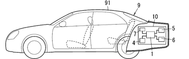
- FIG. 2 is a side view in which a part of the vehicle equipped with the backup power supply system of the above is broken.
- FIG. 3 is a flowchart showing an operation example 1 of the backup power supply system of the above.
- FIG. 4 is a time chart showing an operation example 2 of the backup power supply system of the above.
- FIG. 5 is a diagram showing a configuration of a backup power supply system according to the first modification of the embodiment.
- the backup power supply system 1 is mounted on the vehicle 9 (see FIG. 2), for example, and is used to supply electric power to the load when the main power supply 4 provided in the vehicle 9 fails. That is, the backup power supply system 1 is mounted on the vehicle 9 having the main power supply 4 and the load.
- the term "when the main power supply 4 fails" as used in the present disclosure means that the power supply from the main power supply 4 to the load or the like is stopped due to a failure, deterioration, disconnection, or the like of the main power supply 4.
- the vehicle 9 includes a drive system 10 and a vehicle body (vehicle body) 91 (see FIG. 2) on which the drive system 10 is mounted.
- the drive system 10 includes a backup power supply system 1, a main power supply 4, a plurality of loads (for example, a first load 5 and a second load 6), and an ECU (Electronic Control Unit) 7.
- the main power source 4 is, for example, a battery mounted on a vehicle 9 (a lead storage battery as an example), and is configured to supply electric power to a plurality of loads.
- the ECU 7 is configured to control a plurality of loads provided on the vehicle 9.
- the first load 5 is, for example, a brake system (hereinafter, also referred to as “brake system 5”).
- the second load 6 is, for example, a shift-by-wire system (hereinafter, also referred to as “shift-by-wire system 6”).
- shift-by-wire system 6 is referred to as the "SBW system 6".
- the brake system 5 is a system that electrically operates the brake mechanism provided on each wheel of the vehicle 9.
- the brake system 5 includes a drive control unit 51 and an actuator 52.
- the drive control unit 51 controls the drive of the actuator 52 by outputting a control signal to the actuator 52 based on the amount of operation of the brake pedal by the driver.
- the actuator 52 is configured to operate a braking mechanism provided on each wheel to apply a brake to each wheel in response to a control signal from the drive control unit 51.
- the shift-by-wire system 6 is a system that electrically switches the shift range of the automatic transmission mounted on the vehicle 9.
- the shift-by-wire system 6 includes a drive control unit 61 and an actuator 62.
- the drive control unit 61 controls the drive of the actuator 62 by outputting a control signal to the actuator 62 based on the position of the shift lever operated by the driver.
- the actuator 62 is configured to switch the shift range of the automatic transmission in response to a control signal from the drive control unit 61.
- the shift range of the automatic transmission includes a parking range (P range), a reverse range (R range), a neutral range (N range), and a drive range (D range).
- the drive range is used when the vehicle 9 is moving forward
- the reverse range is used when the vehicle 9 is moving backward
- the parking range is used when the vehicle 9 is parked.
- the actuator 62 locks the rotating shaft in the automatic transmission to lock the movement of the vehicle 9.
- the brake system 5 and the shift-by-wire system 6 are configured to operate by the electric power supplied from the main power supply 4 or the backup power supply system 1.
- the main power supply 4 When the main power supply 4 is normal, power is supplied from the main power supply 4 to the first load 5 and the second load 6 (that is, the brake system 5 and the shift-by-wire system 6). On the other hand, when the main power supply 4 fails, power is supplied from the backup power supply system 1 to the first load 5 and the second load 6. Therefore, even when the main power supply 4 fails, the first load 5 and the second load 6 can operate according to the operation of the driver.
- the backup power supply system 1 includes a first auxiliary power supply 22 and a second auxiliary power supply 3.
- Each of the first auxiliary power source 22 and the second auxiliary power source 3 is an auxiliary power source capable of supplying electric power to the first load (load) 5 when the main power source 4 fails.
- the second time is shorter than the first time.
- the first time is the time until the first auxiliary power supply 22 becomes able to supply electric power to the first load 5.
- the second time is the time until the second auxiliary power supply 3 becomes able to supply electric power to the first load 5. That is, the first time corresponds to the charging time of the first auxiliary power source 22, and the second time corresponds to the charging time of the second auxiliary power source 3.
- the first time and the second time are relative times, respectively.
- the second time corresponding to the charging time of the second auxiliary power supply 3 is shorter than the first time corresponding to the charging time of the first auxiliary power supply 22. Therefore, the charging of the second auxiliary power supply 3 can be completed before the first auxiliary power supply 22. Therefore, power can be supplied to the first load 5 by the second auxiliary power source 3 even during the period until the first time elapses. Therefore, compared to the case where the power is supplied to the first load 5 only by the first auxiliary power supply 22 when the main power supply 4 fails, the power is not supplied to the first load 5 when the main power supply 4 fails. It has the advantage of being less likely to be in a state.
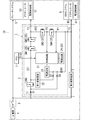
- the backup power supply system 1 includes a backup power supply device 2 and a second auxiliary power supply 3.
- the backup power supply device 2 includes a control circuit 21, a first auxiliary power supply 22, a power supply circuit 23, a drive circuit 24, a plurality of switches SW1 to SW5 (five in FIG. 1), and a plurality of switches SW1 to SW5 (four in FIG. 1). )
- the diodes D1 to D4 are provided.
- the backup power supply device 2 further includes a plurality of input terminals T1 and T2 (two in FIG. 1) and one output terminal T3. That is, in the backup power supply system 1 according to the present embodiment, the first auxiliary power supply 22 and the second auxiliary power supply 3 are separately provided.
- the input terminal T1 is connected to the main power supply 4 via the ignition switch 8.
- the input terminal T1 is a terminal for inputting the power supplied from the main power supply 4 to the backup power supply device 2 when the ignition switch 8 is on.
- the input terminal T2 is connected to the second auxiliary power supply 3.
- the input terminal T2 is a terminal for inputting the power supplied from the second auxiliary power supply 3 to the backup power supply device 2.
- the output terminal T3 is connected to the brake system 5.
- the output terminal T3 is a terminal for outputting the electric power supplied from the first auxiliary power source 22 or the second auxiliary power source 3 to the brake system 5.
- main power supply 4 is connected to the brake system 5 via the ignition switch 8. Therefore, in the brake system 5, when the main power supply 4 is normal and the ignition switch 8 is on, power is also supplied from the main power supply 4.
- control circuit 21 is composed of, for example, a microcomputer having a processor and a memory. That is, the control circuit 21 is realized in a computer system having a processor and a memory. Then, when the processor executes an appropriate program, the computer system functions as the control circuit 21.
- the program may be pre-recorded in a memory, may be recorded through a telecommunication line such as the Internet, or may be recorded and provided on a non-temporary recording medium such as a memory card.
- the control circuit 21 controls at least the drive circuit 24. Specifically, the control circuit 21 outputs the first to fifth control signals for controlling the on / off of the switches SW1 to SW5 to the drive circuit 24.
- the drive circuit 24 controls the on / off of the switches SW1 to SW5 according to the first to fifth control signals from the control circuit 21.
- control circuit 21 has a failure diagnosis function related to the second auxiliary power supply 3.
- control circuit 21 has a first function and a second function.
- the first function is a function of determining whether or not the second auxiliary power supply 3 is normal.
- the second function is a function of determining whether or not the switches SW3 and SW4 provided in the second power supply path 102 from the second auxiliary power supply 3 to the brake system 5 are normal.
- the control circuit 21 measures the voltage at the first midpoint P1 between the input terminal T2 to which the second auxiliary power supply 3 is connected and the switch SW4. The control circuit 21 determines that the second auxiliary power supply 3 is normal if the voltage at the first midpoint P1 is equal to or higher than the first voltage, and if the voltage at the first midpoint P1 is smaller than the first voltage, the second auxiliary power supply 3 is second. It is determined that the auxiliary power supply 3 is abnormal.
- control circuit 21 detects a short circuit (short circuit) and an open (open) of the switches SW3 and SW4 by measuring the voltage of the second midpoint P2 between the switch SW3 and the switch SW4.
- the first auxiliary power supply 22 and the second auxiliary power supply 3 are backup (that is, auxiliary or spare) power supplies for the main power supply 4.
- the first auxiliary power source 22 and the second auxiliary power source 3 are auxiliary power sources capable of supplying electric power to the first load 5 when the main power source 4 fails.
- Each of the first auxiliary power supply 22 and the second auxiliary power supply 3 is, for example, an electric double layer capacitor (EDLC: Electric Double Layer Capacitor).
- EDLC Electric Double Layer Capacitor
- Each of the first auxiliary power source 22 and the second auxiliary power source 3 may be a secondary battery such as a lithium ion capacitor (LIC: Lithium Ion Capacitor) or a lithium ion battery (LIB: Lithium Ion Battery).
- a positive electrode is formed of a material similar to EDLC (for example, activated carbon), and a negative electrode is formed of a material similar to LIB (for example, a carbon material such as graphite).
- each of the first auxiliary power supply 22 and the second auxiliary power supply 3 is not limited to the electric double layer capacitor, and may be, for example, an electrochemical device having the configuration described below.
- the electrochemical device referred to here includes a positive electrode member, a negative electrode member, and a non-aqueous electrolytic solution.
- the positive electrode member includes a positive electrode current collector and a positive electrode material layer supported on the positive electrode current collector and containing a positive electrode active material.
- the positive electrode material layer contains a conductive polymer as a positive electrode active material that is doped and dedoped with anions (dopants).
- the negative electrode member has a negative electrode material layer containing a negative electrode active material.
- the negative electrode active material is, for example, a substance in which a redox reaction accompanied by occlusion and release of lithium ions proceeds, and specifically, a carbon material, a metal compound, an alloy, a ceramic material, or the like.
- the non-aqueous electrolyte solution has lithium ion conductivity as an example.
- This type of non-aqueous electrolyte contains a lithium salt and a non-aqueous solution that dissolves the lithium salt.
- An electrochemical device having such a configuration has a higher energy density than an electric double layer capacitor or the like.
- each of the first auxiliary power supply 22 and the second auxiliary power supply 3 is composed of two or more power storage devices (for example, an electric double layer capacitor) electrically connected in parallel, in series, or in parallel and in series. May be. That is, one first auxiliary power supply 22 and one second auxiliary power supply 3 may be realized by a parallel circuit or a series circuit of two or more power storage devices, or a combination thereof.
- the capacitance of the second auxiliary power supply 3 is smaller than the capacitance of the first auxiliary power supply 22. Therefore, when the first auxiliary power supply 22 and the second auxiliary power supply 3 are charged at the same time, the second time, which is the charging time of the second auxiliary power supply 3, is larger than the first time, which is the charging time of the first auxiliary power supply 22. Will also be shorter. In other words, during the second time until the second auxiliary power supply 3 can supply power to the first load 5, the first auxiliary power supply 22 can supply power to the first load 5. It is shorter than the first time to become.
- the second auxiliary power supply 3 is configured to supply power to both the first load 5 and the second load 6. Therefore, the second auxiliary power source 3 has a (electrostatic) capacity capable of supplying electric power to both the first load 5 and the second load 6.
- the first auxiliary power supply 22 and the second auxiliary power supply 3 are charged by the electric power supplied from the main power supply 4. Specifically, when the ignition switch 8 is turned on and the switch SW5 is turned on, the first auxiliary power source 22 is supplied with electric power from the main power source 4 and is charged by this electric power. Further, when the ignition switch 8 is turned on, the second auxiliary power source 3 is supplied with electric power from the main power source 4 and is charged by this electric power. Further, the first auxiliary power supply 22 and the second auxiliary power supply 3 are configured to discharge when the ignition switch 8 is turned off. Therefore, when the ignition switch 8 is turned on again, the first auxiliary power supply 22 and the second auxiliary power supply 3 are in an uncharged state.
- the "uncharged state" as used in the present disclosure means a fully charged state, that is, a state in which the remaining amount of electric energy is less than a state in which electric energy is sufficiently stored.
- the power supply circuit 23 is a circuit that generates an operating voltage of the control circuit 21.
- the power supply circuit 23 lowers the output voltage of the main power supply 4 input via the input terminals T1 and the diodes D1 and D3 to a predetermined voltage (for example, 5V) and outputs the output voltage to the control circuit 21. Further, the power supply circuit 23 lowers the output voltage of the first auxiliary power supply 22 input via the diode D2 to a predetermined voltage (for example, 5V) and outputs the output voltage to the control circuit 21. Further, the power supply circuit 23 lowers the output voltage of the second auxiliary power supply 3 input via the diode D4 to a predetermined voltage (for example, 5V) and outputs the output voltage to the control circuit 21.
- the control circuit 21 can be operated by the output power of the power supply circuit 23.
- the drive circuit 24 is configured to control a plurality of switches SW1 to SW5 separately. Specifically, the drive circuit 24 creates first to fifth drive signals for turning on / off the switches SW1 to SW5 according to the first to fifth control signals from the control circuit 21, and the created first first. The fifth drive signal is output to the switches SW1 to SW5. The switches SW1 to SW5 are turned on / off according to the first to fifth drive signals from the drive circuit 24.
- Each of the plurality of switches SW1 to SW5 is, for example, an enhancement type P-channel MOSFET (Metal Oxide Semiconductor Field Effect Transistor).
- the plurality of switches SW1 to SW5 are turned on / off according to the first to fifth drive signals output from the drive circuit 24.
- the switches SW1 and SW2 are provided between the first auxiliary power supply 22 and the output terminal T3 in the first power supply path 101 connecting the input terminal T1 and the output terminal T3.
- the switches SW1 and SW2 are connected in series with each other in the first power supply path 101.
- the source of the switch SW1 is connected to the first auxiliary power supply 22, and the drain of the switch SW1 is connected to the drain of the switch SW2. Further, the source of the switch SW2 is connected to the output terminal T3. Then, by turning on the switches SW1 and SW2 together, the electric power stored in the first auxiliary power source 22 can be supplied to the brake system 5 via the switches SW1 and SW2.
- the switches SW3 and SW4 are provided in the second power supply path 102 connecting the input terminal T2 and the output terminal T3.
- the switches SW3 and SW4 are connected in series with each other in the second power supply path 102.
- the source of the switch SW4 is connected to the input terminal T2, and the drain of the switch SW4 is connected to the drain of the switch SW3. Further, the source of the switch SW3 is connected to the output terminal T3. Then, by turning on the switches SW3 and SW4 together, the electric power stored in the second auxiliary power source 3 can be supplied to the brake system 5 via the switches SW3 and SW4.
- the backup power supply system 1 is configured to supply power to the brake system 5 from one of the auxiliary power supplies 22 of the first auxiliary power supply 22 and the second auxiliary power supply 3. Therefore, when the switches SW1 and SW2 are turned on to supply power to the brake system 5 from the first auxiliary power supply 22, the switches SW3 and SW4 are turned off to stop the power supply from the second auxiliary power supply 3. There is. When the switches SW3 and SW4 are turned on to supply power to the brake system 5 from the second auxiliary power supply 3, the switches SW1 and SW2 are turned off to stop the power supply from the first auxiliary power supply 22. There is.
- the switching circuit 25 is configured by the switches SW1 to SW4 and the drive circuit 24. That is, in the backup power supply system 1 according to the present embodiment, the first auxiliary power supply 22 supplies power to the first load 5 and the second auxiliary power supply 3 supplies power to the first load 5. A switching circuit 25 for switching between states is further provided.
- the switch SW5 is provided between the input terminal T1 and the first auxiliary power supply 22 in the first power supply path 101 connecting the input terminal T1 and the output terminal T3.
- the source of the switch SW5 is connected to the input terminal T1 via the diode D1, and the drain of the switch SW5 is connected to the first auxiliary power supply 22.
- the first auxiliary power supply 22 can be charged by turning on the ignition switch 8 and the switch SW5. Therefore, even if the ignition switch 8 is on, if the switch SW5 is off, the first auxiliary power supply 22 is not charged.
- the diode D1 is provided between the input terminal T1 and the switch SW5 in the first power supply path 101 connecting the input terminal T1 and the output terminal T3.
- the anode of the diode D1 is connected to the input terminal T1, and the cathode of the diode D1 is connected to the source of the switch SW5.
- the diode D2 is provided between the first auxiliary power supply 22 and the power supply circuit 23.
- the anode of the diode D2 is connected to the first auxiliary power supply 22, and the cathode of the diode D2 is connected to the power supply circuit 23.
- the diode D3 is provided between the connection point of the diode D1 and the switch SW5 and the power supply circuit 23.
- the anode of the diode D3 is connected to the connection point of the diode D1 and the switch SW5, and the cathode of the diode D3 is connected to the power supply circuit 23.
- the diode D4 is provided between the input terminal T2 and the power supply circuit 23.
- the anode of the diode D4 is connected to the input terminal T2, and the cathode of the diode D4 is connected to the power supply circuit 23.
- the diodes D1 and D3 are conductive and the diodes D2 and D4 are non-conducting, so that the main power supply 4
- the output voltage of is input to the power supply circuit 23 via the diodes D1 and D3.
- the power supply circuit 23 lowers the input output voltage of the main power supply 4 to a predetermined voltage (for example, 5V) and outputs it to the control circuit 21.
- the diodes D2 are conductive and the diodes D1, D3, and D4 are non-conducting, so that the first auxiliary power supply is not conducted.
- the output voltage of 22 is input to the power supply circuit 23 via the diode D2. Then, the power supply circuit 23 lowers the input output voltage of the first auxiliary power supply 22 to a predetermined voltage (for example, 5V) and outputs it to the control circuit 21.
- the diodes D4 are conductive and the diodes D1, D2, D3 are non-conducting, so that the second auxiliary power supply is not conducted.
- the output voltage of 3 is input to the power supply circuit 23 via the diode D4. Then, the power supply circuit 23 lowers the input output voltage of the second auxiliary power supply 3 to a predetermined voltage (for example, 5V) and outputs it to the control circuit 21.
- step S1 When the main power supply 4 has not failed, that is, when the main power supply 4 is normal (step S1: No), power is supplied from the main power supply 4 to the first load 5 (step S2).
- the control circuit 21 is configured so that it can be determined whether or not the main power supply 4 has failed by measuring the output voltage of the main power supply 4, for example.
- step S3: Yes When the main power supply 4 has failed (step S1: Yes), has the first time passed since the control circuit 21 started charging the first auxiliary power supply 22 and the second auxiliary power supply 3? Whether or not it is determined (step S3).
- step S3: Yes When the first time has elapsed (step S3: Yes), the control circuit 21 turns on the switches SW1 and SW2 and turns off the switches SW3 and SW4 to turn off the first auxiliary power source 22 to the first load 5. Is supplied with electric power (step S4).
- step S5 On the other hand, when the first time has not elapsed (step S3: No), the control circuit 21 determines whether or not the second time has elapsed (step S5). In this case, since the first time has not elapsed, the first auxiliary power source 22 is not charged until the first load 5 can be supplied with electric power.
- step S5 When the second time has elapsed (step S5: Yes), the control circuit 21 turns on the switches SW3 and SW4 and turns off the switches SW1 and SW2 to turn off the second auxiliary power source 3 to the first load 5. Is supplied with electric power (step S6). On the other hand, when the second time has not elapsed (step S5: No), the control circuit 21 turns off the switches SW1 to SW4 to supply power from both the first auxiliary power supply 22 and the second auxiliary power supply 3. Do not supply.
- the first auxiliary power source 22 Power may be supplied to the first load 5. Further, if the second time has passed while the main power supply 4 is supplying power to the first load 5, the second auxiliary power supply 3 is added to the power supply from the main power supply 4 to the first load 5. Power may be supplied to the first load 5.
- the first auxiliary power supply 22 becomes the first load 5 during the second time until the second auxiliary power supply 3 can supply power to the first load 5.
- power is not supplied to the first load 5 when the main power supply 4 fails, as compared with the case where power is supplied to the first load 5 only by the first auxiliary power supply 22 when the main power supply 4 fails.
- the vehicle 9 traveling at a speed of several km is stopped by the brake system 5, so that the vehicle 9 traveling at a speed of several tens of km is stopped as compared with the case where the vehicle 9 is stopped.
- the power consumption of the brake system 5 is small. Therefore, in remote parking, the vehicle 9 can be stopped even with the second auxiliary power supply 3 having a smaller capacitance than the first auxiliary power supply 22.
- the vehicle 9 running at a speed of several tens of kilometers is stopped, power is supplied to the brake system 5 from the first auxiliary power source 22 having a larger capacitance than the second auxiliary power source 3.
- the second auxiliary power supply 3 has a first load 5 rather than a first state in which the first auxiliary power supply 22 supplies power to the first load (brake system) 5. Power is supplied to the first load 5 in the second state where the power consumption of the first load is small.
- the user (driver or passenger) of the vehicle 9 gives an instruction for remote parking to the ECU 7 of the vehicle 9 using, for example, a dedicated remote controller.
- the ignition switch 8 is off. Therefore, in this case, power is not supplied from the main power source 4 to the first auxiliary power source 22 and the second auxiliary power source 3, and the first auxiliary power source 22 and the second auxiliary power source 3 are not charged. Further, when the ignition switch 8 is off, the electric power stored in the first auxiliary power supply 22 and the second auxiliary power supply 3 is discharged, so that the first auxiliary power supply 22 and the second auxiliary power supply 3 are in an uncharged state. is there.
- the ECU 7 When the remote parking instruction is given to the ECU 7, the ECU 7 turns on the ignition switch 8 and starts charging the second auxiliary power source 3.
- the ignition switch 8 When the ignition switch 8 is turned on, power is supplied from the main power supply 4 to the power supply circuit 23, and the control circuit 21 is activated by the output power of the power supply circuit 23.
- the permission flag F3 is turned off, and remote parking cannot be performed.
- all of the switches SW1 to SW5 are off.
- the first auxiliary power source 22 is not charged, and only the second auxiliary power source 3 is charged. That is, the second auxiliary power source 3 is charged with priority over the first auxiliary power source 22 by the electric power supplied from the main power source 4.
- the ECU 7 outputs a request signal (specific signal) Sig1 requesting the execution of remote parking to the control circuit 21.
- the control circuit 21 executes various processes shown below in order to perform remote parking.
- the ECU 7 of the vehicle 9 is an external system.
- the control circuit 21 detects a short circuit (short circuit) of the switches SW2 and SW3 before the time t1. At this time, the control circuit 21 detects a short circuit of the switch SW2 by measuring the voltage at the third midpoint between the switches SW1 and SW2 while the switches SW1 to SW4 are off, and detects a short circuit between the switches SW3 and SW4. A short circuit of the switch SW3 is detected by measuring the voltage at the midpoint P2. Further, the control circuit 21 turns on the switch SW3 at time t1 and measures the voltage between the switches SW3 and SW4 to detect the opening of the switch SW3. The control circuit 21 turns off the switch SW3 at the time t2.
- the control circuit 21 turns on the request flag F2 at time t2 if the switch SW3 is not short-circuited and is not open.
- the control circuit 21 measures the voltage at the first midpoint P1, and if this voltage is equal to or higher than the first voltage, it determines that power is being output from the second auxiliary power supply 3. Then, the control circuit 21 turns on the output flag F1 (see FIG. 4). At this time, since the switches SW3 and SW4 are off, the output power of the second auxiliary power supply 3 is supplied to the shift-by-wire system 6, but not to the brake system 5.
- the control circuit 21 detects a short circuit of the switch SW4 in the period from time t2 to time t3.
- the control circuit 21 detects a short circuit of the switch SW4 by measuring the voltage of the second midpoint P2 between the switches SW3 and SW4 while the switches SW3 and SW4 are off. If the switch SW4 is not short-circuited, the control circuit 21 detects the opening of the switch SW4 by turning on the switch SW4. The control circuit 21 detects the opening of the switch SW4 by measuring the voltage of the second midpoint P2 between the switches SW3 and SW4.
- the control circuit 21 turns on the switch SW3 at time t4 if the switch SW4 is not short-circuited and is not open. At this time, the control circuit 21 turns off the request flag F2. At this time, since the switches SW3 and SW4 are both turned on, the output power of the second auxiliary power source 3 is supplied to both the brake system 5 and the shift-by-wire system 6.
- the permission flag F3 is turned on because the second auxiliary power source 3 is in a state where power can be supplied to the brake system (first load) 5 and remote parking is possible.
- an authorization signal is output to the ECU 7.
- the ECU 7 Upon receiving the permission signal from the control circuit 21, the ECU 7 transmits an operable signal indicating that remote parking is possible to the remote controller. Remote parking is started when the user performs a specific operation (operation for performing remote parking) on the remote controller that has received the operable signal.
- the control circuit 21 turns on the charge permission flag F5 and turns on the switch SW5 to start charging the first auxiliary power source 22.
- the control circuit 21 turns off the output flag F1 because the output voltage of the second auxiliary power supply 3 is equal to or lower than the first voltage at time t6.
- the control circuit 21 turns off the permission flag F3 because the output voltage of the second auxiliary power supply 3 is equal to or lower than the first voltage and is not in a state where power can be supplied to the brake system 5.
- the control circuit 21 turns on the prohibition flag F4 when the permission flag F3 is turned from on to off at the time t8.
- the control circuit 21 turns off the switches SW3 and SW4 at time t9, and stops the power supply from the second auxiliary power source 3 to the brake system 5.
- the control circuit 21 detects a short circuit of the switch SW1 in the period from time t9 to time t10.
- the control circuit 21 detects a short circuit of the switch SW1 by measuring the voltage at the third midpoint between the switches SW1 and SW2 while the switches SW1 and SW2 are off.
- the control circuit 21 detects that the switches SW1 and SW2 are open if the switches SW1 and SW2 are not short-circuited.
- the control circuit 21 turns on the switches SW1 and SW2 at time t10 and measures the voltage at the third midpoint between the switches SW1 and SW2 to detect the opening of the switches SW1 and SW2.
- the control circuit 21 turns off the switches SW1 and SW2 and turns on the switches SW3 and SW4 at time t11. Then, at time t12, the control circuit 21 outputs because the output voltage of the second auxiliary power supply 3 is equal to or higher than the first voltage and is in a state where power can be supplied to the brake system 5.
- the flag F1 is turned on and the permission flag F3 is turned on.
- the control circuit 21 Since the first auxiliary power source 22 has been charged at time t13, the control circuit 21 turns off the switches SW3 and SW4 in order to stop the power supply from the second auxiliary power source 3 to the brake system 5. To do. As a result, the power supply from the second auxiliary power source 3 to the brake system 5 is stopped. Then, after time t13, since the first auxiliary power supply 22 is in a state where power can be supplied to the brake system 5, the control circuit 21 turns on the switches SW1 and SW2 to turn on the first auxiliary power supply 22. Power is supplied to the brake system 5.
- the first auxiliary power supply 22 becomes the first load 5 during the second time until the second auxiliary power supply 3 can supply power to the first load 5.
- power is not supplied to the first load 5 when the main power supply 4 fails, as compared with the case where power is supplied to the first load 5 only by the first auxiliary power supply 22 when the main power supply 4 fails.
- the first auxiliary power supply 22 and the second auxiliary power supply 3 are charged at the same time, as compared with the case where the second auxiliary power supply 3 is charged at the same time. , The charging time of the second auxiliary power supply 3 can be shortened.
- the second auxiliary power supply 3 when the control circuit 21 receives the request signal (specific signal) Sigma 1 input from the ECU 7 as an external system, the second auxiliary power supply 3 is the first load 5 If the power supply is possible, the second auxiliary power supply 3 is in the power supply capable state, that is, the above permission signal is output to the ECU 7.
- the second auxiliary power source 3 when the engine of the vehicle 9 is started before instructing remote parking with the remote controller, the second auxiliary power source 3 is used during the period from the start of the engine of the vehicle 9 to the instruction of remote parking. Can be charged. Therefore, the power supply to the first load 5 can be started at an earlier timing than in the case where the second auxiliary power supply 3 can be supplied with power after receiving the request signal Sigma 1 from the ECU 7.
- the "power supply enable state" referred to in the present disclosure means that the second auxiliary power supply 3 is charged and can supply power from the second auxiliary power supply 3 to the first load 5, and that the second auxiliary power supply 3 is normal and the switch SW3 is used. , SW4 is normal (the second power supply path 102 from the second auxiliary power source 3 to the first load 5 is normal).
- the above-described embodiment is only one of the various embodiments of the present disclosure.
- the above-described embodiment can be changed in various ways depending on the design and the like as long as the object of the present disclosure can be achieved.
- the same function as the backup power supply system 1 according to the above-described embodiment may be realized by a power supply backup method, a computer program, a non-temporary recording medium on which the computer program is recorded, or the like.
- the power supply backup method is the power supply backup method used for the backup power supply system 1.
- the backup power supply system 1 includes a first auxiliary power supply 22 and a second auxiliary power supply 3 capable of supplying power to the first load (load) 5 when the main power supply 4 fails.
- the second time is shorter than the first time.
- the first time is the time until the first auxiliary power supply 22 becomes able to supply electric power to the first load 5.
- the second time is the time until the second auxiliary power supply 3 becomes able to supply electric power to the first load 5.
- the program according to one aspect is a program for causing one or more processors to execute the above-mentioned power supply backup method.
- the control circuit 21 includes a computer system.
- a computer system mainly consists of a processor and a memory as hardware.
- the program may be pre-recorded in the memory of the computer system, may be provided through a telecommunications line, and may be recorded on a non-temporary recording medium such as a memory card, optical disk, hard disk drive, etc. that can be read by the computer system. May be provided.
- a processor in a computer system is composed of one or more electronic circuits including a semiconductor integrated circuit (IC) or a large scale integrated circuit (LSI).
- the integrated circuit such as IC or LSI referred to here has a different name depending on the degree of integration, and includes an integrated circuit called a system LSI, VLSI (Very Large Scale Integration), or ULSI (Ultra Large Scale Integration).
- an FPGA Field-Programmable Gate Array
- a plurality of electronic circuits may be integrated on one chip, or may be distributed on a plurality of chips.
- the plurality of chips may be integrated in one device, or may be distributed in a plurality of devices.
- the computer system referred to here includes a microprocessor having one or more processors and one or more memories. Therefore, the microprocessor is also composed of one or a plurality of electronic circuits including a semiconductor integrated circuit or a large-scale integrated circuit.
- the backup power supply system 1 it is not an essential configuration for the backup power supply system 1 that a plurality of functions in the backup power supply system 1 are integrated in one housing. That is, the components of the backup power supply system 1 may be distributed in a plurality of housings. Further, at least a part of the functions of the backup power supply system 1, for example, the functions of the control circuit 21 may be realized by the cloud (cloud computing) or the like.
- the backup power supply system 1A according to the first modification includes the backup power supply device 2A.
- the backup power supply device 2A includes a control circuit 21, a first auxiliary power supply 22A, a power supply circuit 23, a drive circuit 24, a plurality of switches SW1 to SW5 (five in FIG. 5), and a plurality of switches SW1 to SW5 (four in FIG. 5). )
- the diodes D1 to D4 are provided.
- the backup power supply device 2A further includes a plurality of input terminals T1 and T2 (two in FIG. 5) and one output terminal T3.
- the configurations other than the first auxiliary power supply 22A are the same as those of the backup power supply system 1 according to the above-described embodiment, and the description thereof will be omitted here.
- the first auxiliary power supply 22A has, for example, a series circuit in which five electric double layer capacitors are connected in series between the first power supply path 101 and the ground.
- the second auxiliary power supply 3A is made up of the electric double layer capacitors that are connected to the position closest to the ground. That is, in the backup power supply system 1A according to the first modification, the first auxiliary power supply 22A includes the second auxiliary power supply 3A.
- the electric double layer capacitor connected to the position closest to the ground is charged in order among the five electric double layer capacitors, so that the second auxiliary power supply 3A is preferentially charged. be able to.
- the backup power supply system 1A according to the first modification is configured to preferentially charge the second auxiliary power supply 3A as described above. Therefore, even during the period until the first auxiliary power source 22A is charged, the second auxiliary power source 3A can supply electric power to the first load 5. Therefore, as compared with the case where the power is supplied to the first load 5 only by the first auxiliary power supply 22A when the main power supply 4 fails, the power is not supplied to the first load 5 when the main power supply 4 fails. It has the advantage of being difficult to become.
- the power supplied from the main power supply 4 is used to prioritize the charging of the second auxiliary power supply 3 over the first auxiliary power supply 22, but the first auxiliary power supply 22 and the second auxiliary power supply 3 are charged.
- charging may be performed at the same time. In this case, for example, by turning on the switch SW5 at the timing when the control circuit 21 is activated, the first auxiliary power supply 22 and the second auxiliary power supply 3 can be charged at the same time.
- the switching circuit 25 switches between a state in which power is supplied from the first auxiliary power supply 22 to the first load 5 and a state in which power is supplied from the second auxiliary power supply 3 to the first load 5. ..
- it may be configured to supply power to the first load 5 from both the first auxiliary power source 22 and the second auxiliary power source 3.
- the second load is the shift-by-wire system 6, but the second load is not limited to the shift-by-wire system 6, and may be, for example, a door lock system that locks the door of the vehicle 9.
- remote parking is performed using a remote controller
- remote parking may be performed using a smartphone, tablet, or the like that has downloaded a dedicated application.
- the control circuit 21 when the control circuit 21 receives the request signal Sigma 1 from the ECU 7, if the second auxiliary power supply 3 is in a power supply capable state, the ECU 7 is informed that the second auxiliary power supply 3 is in a power supply possible state. It is outputting.
- the second auxiliary power source 3 after receiving the request signal Sigma 1 from the ECU 7, the second auxiliary power source 3 may be set to a state in which electric power can be supplied to the first load 5. As a result, the second auxiliary power supply 3 can be made available for power supply by the request signal Sigma 1 from the ECU 7.
- the backup power supply system (1; 1A) is the first auxiliary power supply (22;) capable of supplying power to the load (5) when the main power supply (4) fails. 22A) and a second auxiliary power source (3; 3A).
- the second time is shorter than the first time.
- the first time is the time until the first auxiliary power source (22; 22A) becomes able to supply electric power to the load (5).
- the second time is the time until the second auxiliary power source (3; 3A) becomes able to supply electric power to the load (5).
- the second auxiliary power supply (3; 3A) supplies power to the load (5) until the first auxiliary power supply (22; 22A) can supply power to the load (5). It can supply power.
- the load (4) fails when the main power source (4) fails, as compared with the case where power is supplied to the load (5) only by the first auxiliary power source (22; 22A) when the main power source (4) fails.
- 5) has the advantage that it is unlikely that power will not be supplied.
- the first auxiliary power supply (22; 22A) and the second auxiliary power supply (3; 3A) are supplied from the main power supply (4). It is charged by the electric power generated.
- the first auxiliary power supply (22; 22A) and the second auxiliary power supply (3; 3A) can be charged by the electric power supplied from the main power supply (4).
- the capacity of the second auxiliary power supply (3; 3A) is larger than the capacity of the first auxiliary power supply (22; 22A). small.
- the second auxiliary power supply (22; 22A) takes less time than the first auxiliary power supply (22; 22A).
- the power supply (3; 3A) can be charged.
- the second auxiliary power supply (3; 3A) is the second by the electric power supplied from the main power supply (4). 1 It is charged with priority over the auxiliary power supply (22; 22A).
- the second auxiliary power supply (3; 3A) is charged in a shorter time than when the first auxiliary power supply (22; 22A) and the second auxiliary power supply (3; 3A) are charged at the same time. be able to.
- the first auxiliary power supply (22A) includes the second auxiliary power supply (3A).
- the backup power supply system (1; 1A) according to the sixth aspect is mounted on the vehicle (9) including the main power source (4) and the load (5) in any one of the first to fifth aspects.
- the second auxiliary power supply (3; 3A) is the first load (5) and the first load as a load. Power can be supplied to both the second load (6), which is different from the load (5).
- power can be supplied to both the first load (5) and the second load (6) when the main power supply (4) fails.
- the second auxiliary power supply (3; 3A) is applied to at least both the first load (5) and the second load (6).
- it has a capacity that can supply electric power.
- power can be supplied to both the first load (5) and the second load (6) when the main power supply (4) fails.
- the second auxiliary power source (3; 3A) supplies power to the load (5) in the second state. To do. In the second state, the power consumption of the load (5) is smaller than that in the first state in which the first auxiliary power supply (22; 22A) supplies power to the load (5).
- the load (5) in the second state, can be operated by the electric power supplied from the second auxiliary power source (3; 3A).
- the backup power supply system (1; 1A) according to the tenth aspect further includes a switching circuit (25) in any one of the first to ninth aspects.
- the switching circuit (25) the first auxiliary power supply (22; 22A) supplies power to the load (5), and the second auxiliary power supply (3; 3A) supplies power to the load (5). Switch between the supply state and the supply state.
- a state in which the first auxiliary power supply (22; 22A) supplies power to the load (5) and a state in which the second auxiliary power supply (3; 3A) supplies power to the load (5). Can be switched.
- the backup power supply system (1; 1A) receives a specific signal (Sigma1) from the external system (7) in any one of the first to tenth aspects, and the second auxiliary power supply (1; 1A). If 3; 3A) is in a power supply capable state, the fact that the second auxiliary power supply (3; 3A) is in a power supply capable state is output to the external system (13).
- the power supply available state is a state in which the second auxiliary power source (3; 3A) can supply power to the load (5).
- the load (5) is more affected. Power supply can be started at an early timing.
- the backup power supply system (1; 1A) in any one of the first to tenth aspects, after receiving the specific signal (Sigma1) input from the external system (7), the second auxiliary power supply (1; 1A) 3; 3A) is put into a state where power can be supplied to the load (5).
- the second auxiliary power supply (3; 3A) can be made available for power supply by the specific signal (Sigma1) input from the external system (7).
- the backup power supply system (1; 1A) according to the thirteenth aspect has a failure diagnosis function regarding the second auxiliary power supply (3; 3A) in any one of the first to twelfth aspects.
- a failure diagnosis regarding the second auxiliary power supply (3; 3A) can be performed.
- the power supply backup method is the power supply backup method used in the backup power supply system (1; 1A).
- the backup power supply system (1; 1A) is a first auxiliary power supply (22; 22A) and a second auxiliary power supply (3; 3A) capable of supplying power to the load (5) when the main power supply (4) fails.
- the second time is shorter than the first time.
- the first time is the time until the first auxiliary power source (22; 22A) becomes able to supply electric power to the load (5).
- the second time is the time until the second auxiliary power source (3; 3A) becomes able to supply electric power to the load (5).
- the second auxiliary power supply (3; 3A) supplies power to the load (5) until the first auxiliary power supply (22; 22A) can supply power to the load (5). It can supply power.
- the load (4) fails when the main power source (4) fails, as compared with the case where power is supplied to the load (5) only by the first auxiliary power source (22; 22A) when the main power source (4) fails.
- 5) has the advantage that it is unlikely that power will not be supplied.
- the program according to the fifteenth aspect is a program for causing one or more processors to execute the power supply backup method according to the fourteenth aspect.
- the second auxiliary power supply (3; 3A) supplies power to the load (5) until the first auxiliary power supply (22; 22A) can supply power to the load (5). It can supply power.
- the load (4) fails when the main power source (4) fails, as compared with the case where power is supplied to the load (5) only by the first auxiliary power source (22; 22A) when the main power source (4) fails.
- 5) has the advantage that it is unlikely that power will not be supplied.
- the configurations according to the second to thirteenth aspects are not essential configurations for the backup power supply system (1; 1A) and can be omitted as appropriate.
Abstract
A backup power supply system 1 according to the present invention is provided with a first auxiliary power supply 22 and a second auxiliary power supply 3 that are able to supply power to a first load 5 when failure of a main power supply 4 has occurred. In the backup power supply system 1, a second time is shorter than a first time. The first time is the time required until the first auxiliary power supply 22 can supply power to the first load 5. The second time is the time required until the second auxiliary power supply 3 can supply power to the first load 5.
Description
本開示は、一般にバックアップ電源システム、電源バックアップ方法及びプログラムに関する。より詳細には、本開示は、主電源の失陥時に負荷に対して電力を供給可能なバックアップ電源システム、電源バックアップ方法及びプログラムに関する。
This disclosure generally relates to backup power systems, power backup methods and programs. More specifically, the present disclosure relates to backup power systems, power backup methods and programs capable of supplying power to a load in the event of a mains failure.
特許文献1には、車両の外部から携帯端末を用いて車両に駐車動作を実行させることが可能な駐車支援装置が記載されている。特許文献1に記載の駐車支援装置では、車両に電源失陥が発生している場合に、車両のシフトをPレンジに固定させることが可能なPロックアクチュエータ、及びEPB(Electronic Parking Brake)を制御するEPBアクチュエータの解除方法を携帯端末に出力する。
Patent Document 1 describes a parking support device capable of causing a vehicle to execute a parking operation from the outside of the vehicle using a mobile terminal. The parking support device described in Patent Document 1 controls a P-lock actuator capable of fixing the shift of the vehicle to the P range and an EPB (Electronic Parking Brake) when a power failure occurs in the vehicle. Output the release method of the EPB actuator to the mobile terminal.
本開示の目的は、主電源の失陥時に負荷に対して電力が供給されない状態になりにくいバックアップ電源システム、電源バックアップ方法及びプログラムを提供することにある。
An object of the present disclosure is to provide a backup power supply system, a power supply backup method, and a program in which power is unlikely to be supplied to a load when the main power supply fails.
本開示の一態様に係るバックアップ電源システムは、主電源の失陥時に負荷に対して電力を供給可能な第1補助電源及び第2補助電源を備える。前記バックアップ電源システムでは、第2時間は、第1時間よりも短い。前記第1時間は、前記第1補助電源が前記負荷に対して電力を供給可能な状態になるまでの時間である。前記第2時間は、前記第2補助電源が前記負荷に対して電力を供給可能な状態になるまでの時間である。
The backup power supply system according to one aspect of the present disclosure includes a first auxiliary power supply and a second auxiliary power supply capable of supplying power to a load when the main power supply fails. In the backup power supply system, the second time is shorter than the first time. The first time is the time until the first auxiliary power source becomes able to supply electric power to the load. The second time is the time until the second auxiliary power source becomes able to supply electric power to the load.
本開示の一態様に係る電源バックアップ方法は、バックアップ電源システムに用いられる電源バックアップ方法である。前記バックアップ電源システムは、主電源の失陥時に負荷に対して電力を供給可能な第1補助電源及び第2補助電源を備える。前記バックアップ電源システムでは、第2時間は、第1時間よりも短い。前記第1時間は、前記第1補助電源が前記負荷に対して電力を供給可能な状態になるまでの時間である。前記第2時間は、前記第2補助電源が前記負荷に対して電力を供給可能な状態になるまでの時間である。
The power supply backup method according to one aspect of the present disclosure is a power supply backup method used in a backup power supply system. The backup power supply system includes a first auxiliary power supply and a second auxiliary power supply capable of supplying power to a load when the main power supply fails. In the backup power supply system, the second time is shorter than the first time. The first time is the time until the first auxiliary power source becomes able to supply electric power to the load. The second time is the time until the second auxiliary power source becomes able to supply electric power to the load.
本開示の一態様に係るプログラムは、前記電源バックアップ方法を、1以上のプロセッサに実行させるためのプログラムである。
The program according to one aspect of the present disclosure is a program for causing one or more processors to execute the power backup method.
本開示によれば、主電源の失陥時に負荷に対して電力が供給されない状態になりにくい、という効果がある。
According to the present disclosure, there is an effect that it is difficult for power to be supplied to the load when the main power supply fails.
(実施形態)
以下に説明する実施形態及び変形例は、本開示の一例に過ぎず、本開示は、下記の実施形態及び変形例に限定されない。下記の実施形態及び変形例以外であっても、本開示の技術的思想を逸脱しない範囲であれば、設計等に応じて種々の変更が可能である。 (Embodiment)
The embodiments and modifications described below are merely examples of the present disclosure, and the present disclosure is not limited to the following embodiments and modifications. Other than the following embodiments and modifications, various changes can be made according to the design and the like as long as they do not deviate from the technical idea of the present disclosure.
(1)概要
まず、実施形態に係るバックアップ電源システム1の概要について、図1及び図2を参照して説明する。 (1) Outline First, an outline of the backuppower supply system 1 according to the embodiment will be described with reference to FIGS. 1 and 2.
まず、実施形態に係るバックアップ電源システム1の概要について、図1及び図2を参照して説明する。 (1) Outline First, an outline of the backup
本実施形態に係るバックアップ電源システム1は、例えば、車両9(図2参照)に搭載され、車両9に設けられた主電源4の失陥時に負荷に対して電力を供給するために用いられる。つまり、バックアップ電源システム1は、主電源4と負荷とを備える車両9に搭載される。本開示でいう「主電源4の失陥時」とは、主電源4の故障、劣化又は断線等によって主電源4から負荷等への電力の供給が停止することをいう。
The backup power supply system 1 according to the present embodiment is mounted on the vehicle 9 (see FIG. 2), for example, and is used to supply electric power to the load when the main power supply 4 provided in the vehicle 9 fails. That is, the backup power supply system 1 is mounted on the vehicle 9 having the main power supply 4 and the load. The term "when the main power supply 4 fails" as used in the present disclosure means that the power supply from the main power supply 4 to the load or the like is stopped due to a failure, deterioration, disconnection, or the like of the main power supply 4.
車両9は、駆動システム10と、駆動システム10が搭載される車体(車両本体)91(図2参照)と、を備える。駆動システム10は、バックアップ電源システム1と、主電源4と、複数の負荷(一例として第1負荷5及び第2負荷6)と、ECU(Electronic Control Unit)7と、を有する。主電源4は、例えば、車両9に搭載されたバッテリ(一
例として鉛蓄電池)であり、複数の負荷に電力を供給するように構成されている。ECU7は、車両9に設けられた複数の負荷を制御するように構成されている。 Thevehicle 9 includes a drive system 10 and a vehicle body (vehicle body) 91 (see FIG. 2) on which the drive system 10 is mounted. The drive system 10 includes a backup power supply system 1, a main power supply 4, a plurality of loads (for example, a first load 5 and a second load 6), and an ECU (Electronic Control Unit) 7. The main power source 4 is, for example, a battery mounted on a vehicle 9 (a lead storage battery as an example), and is configured to supply electric power to a plurality of loads. The ECU 7 is configured to control a plurality of loads provided on the vehicle 9.
例として鉛蓄電池)であり、複数の負荷に電力を供給するように構成されている。ECU7は、車両9に設けられた複数の負荷を制御するように構成されている。 The
第1負荷5は、例えば、ブレーキシステム(以下、「ブレーキシステム5」ともいう)である。第2負荷6は、例えば、シフトバイワイヤシステム(以下、「シフトバイワイヤシステム6」ともいう)である。なお、図1では、「シフトバイワイヤシステム6」を「SBWシステム6」と表記している。
The first load 5 is, for example, a brake system (hereinafter, also referred to as “brake system 5”). The second load 6 is, for example, a shift-by-wire system (hereinafter, also referred to as “shift-by-wire system 6”). In FIG. 1, the "shift-by-wire system 6" is referred to as the "SBW system 6".
ブレーキシステム5は、車両9の各車輪に設けられたブレーキ機構を電動で動作させるシステムである。ブレーキシステム5は、駆動制御部51と、アクチュエータ52と、を備える。駆動制御部51は、運転者によるブレーキペダルの操作量に基づいて、アクチュエータ52に制御信号を出力することで、アクチュエータ52の駆動を制御する。アクチュエータ52は、駆動制御部51からの制御信号に応じて、各車輪に設けられたブレーキ機構を動作させて各車輪にブレーキを掛けるように構成されている。
The brake system 5 is a system that electrically operates the brake mechanism provided on each wheel of the vehicle 9. The brake system 5 includes a drive control unit 51 and an actuator 52. The drive control unit 51 controls the drive of the actuator 52 by outputting a control signal to the actuator 52 based on the amount of operation of the brake pedal by the driver. The actuator 52 is configured to operate a braking mechanism provided on each wheel to apply a brake to each wheel in response to a control signal from the drive control unit 51.
シフトバイワイヤシステム6は、車両9に搭載された自動変速機のシフトレンジを電動で切り替えるシステムである。シフトバイワイヤシステム6は、駆動制御部61と、アクチュエータ62と、を備える。駆動制御部61は、運転者が操作するシフトレバーの位置に基づいて、アクチュエータ62に制御信号を出力することで、アクチュエータ62の駆動を制御する。アクチュエータ62は、駆動制御部61からの制御信号に応じて、自動変速機のシフトレンジを切り替えるように構成されている。
The shift-by-wire system 6 is a system that electrically switches the shift range of the automatic transmission mounted on the vehicle 9. The shift-by-wire system 6 includes a drive control unit 61 and an actuator 62. The drive control unit 61 controls the drive of the actuator 62 by outputting a control signal to the actuator 62 based on the position of the shift lever operated by the driver. The actuator 62 is configured to switch the shift range of the automatic transmission in response to a control signal from the drive control unit 61.
自動変速機のシフトレンジには、パーキングレンジ(Pレンジ)、リバースレンジ(Rレンジ)、ニュートラルレンジ(Nレンジ)及びドライブレンジ(Dレンジ)が含まれる。ドライブレンジは、車両9の前進時に使用され、リバースレンジは、車両9の後退時に使用され、パーキングレンジは、車両9の駐車時に使用される。パーキングレンジでは、アクチュエータ62によって自動変速機内の回転シャフトがロックされて、車両9の動きがロックされる。
The shift range of the automatic transmission includes a parking range (P range), a reverse range (R range), a neutral range (N range), and a drive range (D range). The drive range is used when the vehicle 9 is moving forward, the reverse range is used when the vehicle 9 is moving backward, and the parking range is used when the vehicle 9 is parked. In the parking range, the actuator 62 locks the rotating shaft in the automatic transmission to lock the movement of the vehicle 9.
ブレーキシステム5及びシフトバイワイヤシステム6は、主電源4又はバックアップ電源システム1から供給される電力により動作するように構成されている。
The brake system 5 and the shift-by-wire system 6 are configured to operate by the electric power supplied from the main power supply 4 or the backup power supply system 1.
主電源4が正常である場合には、主電源4から第1負荷5及び第2負荷6(すなわちブレーキシステム5及びシフトバイワイヤシステム6)に電力が供給される。一方、主電源4の失陥時には、バックアップ電源システム1から第1負荷5及び第2負荷6に電力が供給される。したがって、主電源4の失陥時においても、第1負荷5及び第2負荷6は、運転者の操作に応じて動作可能となる。
When the main power supply 4 is normal, power is supplied from the main power supply 4 to the first load 5 and the second load 6 (that is, the brake system 5 and the shift-by-wire system 6). On the other hand, when the main power supply 4 fails, power is supplied from the backup power supply system 1 to the first load 5 and the second load 6. Therefore, even when the main power supply 4 fails, the first load 5 and the second load 6 can operate according to the operation of the driver.
バックアップ電源システム1は、第1補助電源22と、第2補助電源3と、を備える。第1補助電源22及び第2補助電源3の各々は、主電源4の失陥時に第1負荷(負荷)5に対して電力を供給可能な補助電源である。バックアップ電源システム1では、第2時間は、第1時間よりも短い。第1時間は、第1補助電源22が第1負荷5に対して電力を供給可能な状態になるまでの時間である。第2時間は、第2補助電源3が第1負荷5に対して電力を供給可能な状態になるまでの時間である。つまり、第1時間は第1補助電源22の充電時間に相当し、第2時間は第2補助電源3の充電時間に相当する。第1時間及び第2時間は、それぞれ相対的な時間である。
The backup power supply system 1 includes a first auxiliary power supply 22 and a second auxiliary power supply 3. Each of the first auxiliary power source 22 and the second auxiliary power source 3 is an auxiliary power source capable of supplying electric power to the first load (load) 5 when the main power source 4 fails. In the backup power supply system 1, the second time is shorter than the first time. The first time is the time until the first auxiliary power supply 22 becomes able to supply electric power to the first load 5. The second time is the time until the second auxiliary power supply 3 becomes able to supply electric power to the first load 5. That is, the first time corresponds to the charging time of the first auxiliary power source 22, and the second time corresponds to the charging time of the second auxiliary power source 3. The first time and the second time are relative times, respectively.
本実施形態に係るバックアップ電源システム1では、上述したように、第2補助電源3の充電時間に相当する第2時間は、第1補助電源22の充電時間に相当する第1時間よりも短い。したがって、第1補助電源22よりも先に第2補助電源3の充電を完了させることができる。そのため、第1時間が経過するまでの期間においても、第2補助電源3によって第1負荷5に対して電力を供給することができる。よって、主電源4の失陥時に第1補助電源22のみで第1負荷5に対して電力を供給する場合に比べて、主電源4の失陥時に第1負荷5に対して電力が供給されない状態になりにくい、という利点がある。
In the backup power supply system 1 according to the present embodiment, as described above, the second time corresponding to the charging time of the second auxiliary power supply 3 is shorter than the first time corresponding to the charging time of the first auxiliary power supply 22. Therefore, the charging of the second auxiliary power supply 3 can be completed before the first auxiliary power supply 22. Therefore, power can be supplied to the first load 5 by the second auxiliary power source 3 even during the period until the first time elapses. Therefore, compared to the case where the power is supplied to the first load 5 only by the first auxiliary power supply 22 when the main power supply 4 fails, the power is not supplied to the first load 5 when the main power supply 4 fails. It has the advantage of being less likely to be in a state.
(2)詳細
次に、実施形態に係るバックアップ電源システム1の詳細について、図1を参照して説明する。 (2) Details Next, the details of the backuppower supply system 1 according to the embodiment will be described with reference to FIG.
次に、実施形態に係るバックアップ電源システム1の詳細について、図1を参照して説明する。 (2) Details Next, the details of the backup
本実施形態に係るバックアップ電源システム1は、図1に示すように、バックアップ電源装置2と、第2補助電源3と、を備える。
As shown in FIG. 1, the backup power supply system 1 according to the present embodiment includes a backup power supply device 2 and a second auxiliary power supply 3.
バックアップ電源装置2は、制御回路21と、第1補助電源22と、電源回路23と、駆動回路24と、複数(図1では5つ)のスイッチSW1~SW5と、複数(図1では4つ)のダイオードD1~D4と、を備える。また、バックアップ電源装置2は、複数(図1では2つ)の入力端子T1,T2と、1つの出力端子T3と、を更に備える。つまり、本実施形態に係るバックアップ電源システム1では、第1補助電源22と第2補助電源3とが別々に設けられている。
The backup power supply device 2 includes a control circuit 21, a first auxiliary power supply 22, a power supply circuit 23, a drive circuit 24, a plurality of switches SW1 to SW5 (five in FIG. 1), and a plurality of switches SW1 to SW5 (four in FIG. 1). ) The diodes D1 to D4 are provided. Further, the backup power supply device 2 further includes a plurality of input terminals T1 and T2 (two in FIG. 1) and one output terminal T3. That is, in the backup power supply system 1 according to the present embodiment, the first auxiliary power supply 22 and the second auxiliary power supply 3 are separately provided.
(2.1)端子
入力端子T1は、イグニッションスイッチ8を介して主電源4に接続されている。入力端子T1は、イグニッションスイッチ8がオンのときに、主電源4から供給される電力をバックアップ電源装置2に入力するための端子である。 (2.1) Terminal The input terminal T1 is connected to themain power supply 4 via the ignition switch 8. The input terminal T1 is a terminal for inputting the power supplied from the main power supply 4 to the backup power supply device 2 when the ignition switch 8 is on.
入力端子T1は、イグニッションスイッチ8を介して主電源4に接続されている。入力端子T1は、イグニッションスイッチ8がオンのときに、主電源4から供給される電力をバックアップ電源装置2に入力するための端子である。 (2.1) Terminal The input terminal T1 is connected to the
入力端子T2は、第2補助電源3に接続されている。入力端子T2は、第2補助電源3から供給される電力をバックアップ電源装置2に入力するための端子である。
The input terminal T2 is connected to the second auxiliary power supply 3. The input terminal T2 is a terminal for inputting the power supplied from the second auxiliary power supply 3 to the backup power supply device 2.
出力端子T3は、ブレーキシステム5に接続されている。出力端子T3は、第1補助電源22又は第2補助電源3から供給される電力をブレーキシステム5に出力するための端子である。
The output terminal T3 is connected to the brake system 5. The output terminal T3 is a terminal for outputting the electric power supplied from the first auxiliary power source 22 or the second auxiliary power source 3 to the brake system 5.
また、ブレーキシステム5には、イグニッションスイッチ8を介して主電源4が接続されている。したがって、ブレーキシステム5は、主電源4が正常であり、かつイグニッションスイッチ8がオンのときには、主電源4からも電力が供給される。
Further, the main power supply 4 is connected to the brake system 5 via the ignition switch 8. Therefore, in the brake system 5, when the main power supply 4 is normal and the ignition switch 8 is on, power is also supplied from the main power supply 4.
(2.2)制御回路
制御回路21は、例えば、プロセッサ及びメモリを有するマイクロコンピュータで構成されている。つまり、制御回路21は、プロセッサ及びメモリを有するコンピュータシステムで実現されている。そして、プロセッサが適宜のプログラムを実行することにより、コンピュータシステムが制御回路21として機能する。プログラムは、メモリに予め記録されていてもよいし、インターネット等の電気通信回線を通じて、又はメモリカード等の非一時的記録媒体に記録されて提供されてもよい。 (2.2) Control circuit Thecontrol circuit 21 is composed of, for example, a microcomputer having a processor and a memory. That is, the control circuit 21 is realized in a computer system having a processor and a memory. Then, when the processor executes an appropriate program, the computer system functions as the control circuit 21. The program may be pre-recorded in a memory, may be recorded through a telecommunication line such as the Internet, or may be recorded and provided on a non-temporary recording medium such as a memory card.
制御回路21は、例えば、プロセッサ及びメモリを有するマイクロコンピュータで構成されている。つまり、制御回路21は、プロセッサ及びメモリを有するコンピュータシステムで実現されている。そして、プロセッサが適宜のプログラムを実行することにより、コンピュータシステムが制御回路21として機能する。プログラムは、メモリに予め記録されていてもよいし、インターネット等の電気通信回線を通じて、又はメモリカード等の非一時的記録媒体に記録されて提供されてもよい。 (2.2) Control circuit The
制御回路21は、少なくとも駆動回路24を制御する。具体的には、制御回路21は、駆動回路24に対して、スイッチSW1~SW5のオン/オフを制御するための第1~第5制御信号を出力する。駆動回路24は、制御回路21からの第1~第5制御信号に従って、スイッチSW1~SW5のオン/オフを制御する。
The control circuit 21 controls at least the drive circuit 24. Specifically, the control circuit 21 outputs the first to fifth control signals for controlling the on / off of the switches SW1 to SW5 to the drive circuit 24. The drive circuit 24 controls the on / off of the switches SW1 to SW5 according to the first to fifth control signals from the control circuit 21.
また、制御回路21は、第2補助電源3に関する故障診断の機能を有する。具体的には、制御回路21は、第1機能と、第2機能と、を有する。第1機能は、第2補助電源3が正常か否かを判定する機能である。第2機能は、第2補助電源3からブレーキシステム5への第2給電路102に設けられているスイッチSW3,SW4が正常か否かを判定する機能である。
Further, the control circuit 21 has a failure diagnosis function related to the second auxiliary power supply 3. Specifically, the control circuit 21 has a first function and a second function. The first function is a function of determining whether or not the second auxiliary power supply 3 is normal. The second function is a function of determining whether or not the switches SW3 and SW4 provided in the second power supply path 102 from the second auxiliary power supply 3 to the brake system 5 are normal.
制御回路21は、第1機能では、第2補助電源3が接続されている入力端子T2とスイッチSW4との間の第1中点P1の電圧を計測する。制御回路21は、第1中点P1の電圧が第1電圧以上であれば第2補助電源3が正常であると判定し、第1中点P1の電圧が第1電圧よりも小さければ第2補助電源3が異常であると判定する。
In the first function, the control circuit 21 measures the voltage at the first midpoint P1 between the input terminal T2 to which the second auxiliary power supply 3 is connected and the switch SW4. The control circuit 21 determines that the second auxiliary power supply 3 is normal if the voltage at the first midpoint P1 is equal to or higher than the first voltage, and if the voltage at the first midpoint P1 is smaller than the first voltage, the second auxiliary power supply 3 is second. It is determined that the auxiliary power supply 3 is abnormal.
制御回路21は、第2機能では、スイッチSW3とスイッチSW4との間の第2中点P2の電圧を計測することで、スイッチSW3,SW4の短絡(ショート)及び開放(オープン)を検出する。
In the second function, the control circuit 21 detects a short circuit (short circuit) and an open (open) of the switches SW3 and SW4 by measuring the voltage of the second midpoint P2 between the switch SW3 and the switch SW4.
(2.3)補助電源
第1補助電源22及び第2補助電源3は、主電源4のバックアップ用(すなわち補助又は予備)の電源である。言い換えると、第1補助電源22及び第2補助電源3は、主電源4の失陥時に第1負荷5に対して電力を供給可能な補助電源である。 (2.3) Auxiliary power supply The firstauxiliary power supply 22 and the second auxiliary power supply 3 are backup (that is, auxiliary or spare) power supplies for the main power supply 4. In other words, the first auxiliary power source 22 and the second auxiliary power source 3 are auxiliary power sources capable of supplying electric power to the first load 5 when the main power source 4 fails.
第1補助電源22及び第2補助電源3は、主電源4のバックアップ用(すなわち補助又は予備)の電源である。言い換えると、第1補助電源22及び第2補助電源3は、主電源4の失陥時に第1負荷5に対して電力を供給可能な補助電源である。 (2.3) Auxiliary power supply The first
第1補助電源22及び第2補助電源3の各々は、例えば、電気二重層キャパシタ(EDLC:Electrical Double Layer Capacitor)である。なお、第1補助電源22及び第2補助電源3の各々は、リチウムイオンキャパシタ(LIC:Lithium Ion Capacitor)、又はリチウムイオン電池(LIB:Lithium Ion Battery)等の二次電池であってもよい。リチウムイオンキャパシタでは、EDLCと同様の材質(例えば活性炭)で正極が形成され、LIBと同様の材質(例えば黒鉛等の炭素材料)で負極が形成される。
Each of the first auxiliary power supply 22 and the second auxiliary power supply 3 is, for example, an electric double layer capacitor (EDLC: Electric Double Layer Capacitor). Each of the first auxiliary power source 22 and the second auxiliary power source 3 may be a secondary battery such as a lithium ion capacitor (LIC: Lithium Ion Capacitor) or a lithium ion battery (LIB: Lithium Ion Battery). In a lithium ion capacitor, a positive electrode is formed of a material similar to EDLC (for example, activated carbon), and a negative electrode is formed of a material similar to LIB (for example, a carbon material such as graphite).
また、第1補助電源22及び第2補助電源3の各々は、電気二重層キャパシタに限らず、例えば、以下に説明する構成を有する電気化学デバイスであってもよい。ここでいう電気化学デバイスは、正極部材と、負極部材と、非水電解液と、を備える。正極部材は、正極集電体と、正極集電体に担持され正極活物質を含む正極材料層と、を有する。正極材料層は、アニオン(ドーパント)をドープ及び脱ドープする正極活物質として導電性高分子を含む。負極部材は、負極活物質を含む負極材料層を有する。負極活物質は、一例として、リチウムイオンの吸蔵及び放出を伴う酸化還元反応が進行する物質であり、具体的には、炭素材料、金属化合物、合金又はセラミックス材料等である。非水電解液は、一例として、リチウムイオン伝導性を有する。この種の非水電解液は、リチウム塩と、リチウム塩を溶解させる非水溶液と、を含んでいる。このような構成の電気化学デバイスは、電気二重層キャパシタ等に比べて、高いエネルギ密度を有する。
Further, each of the first auxiliary power supply 22 and the second auxiliary power supply 3 is not limited to the electric double layer capacitor, and may be, for example, an electrochemical device having the configuration described below. The electrochemical device referred to here includes a positive electrode member, a negative electrode member, and a non-aqueous electrolytic solution. The positive electrode member includes a positive electrode current collector and a positive electrode material layer supported on the positive electrode current collector and containing a positive electrode active material. The positive electrode material layer contains a conductive polymer as a positive electrode active material that is doped and dedoped with anions (dopants). The negative electrode member has a negative electrode material layer containing a negative electrode active material. The negative electrode active material is, for example, a substance in which a redox reaction accompanied by occlusion and release of lithium ions proceeds, and specifically, a carbon material, a metal compound, an alloy, a ceramic material, or the like. The non-aqueous electrolyte solution has lithium ion conductivity as an example. This type of non-aqueous electrolyte contains a lithium salt and a non-aqueous solution that dissolves the lithium salt. An electrochemical device having such a configuration has a higher energy density than an electric double layer capacitor or the like.
また、第1補助電源22及び第2補助電源3の各々は、電気的に並列、直列、又は並列かつ直列に接続された、2個以上の蓄電デバイス(例えば電気二重層キャパシタ)にて構成されていてもよい。すなわち、2個以上の蓄電デバイスの並列回路若しくは直列回路、又はその組み合わせによって、1つの第1補助電源22及び1つの第2補助電源3がそれぞれ実現されてもよい。
Further, each of the first auxiliary power supply 22 and the second auxiliary power supply 3 is composed of two or more power storage devices (for example, an electric double layer capacitor) electrically connected in parallel, in series, or in parallel and in series. May be. That is, one first auxiliary power supply 22 and one second auxiliary power supply 3 may be realized by a parallel circuit or a series circuit of two or more power storage devices, or a combination thereof.
ここで、本実施形態に係るバックアップ電源システム1では、第2補助電源3の静電容量は、第1補助電源22の静電容量よりも小さい。したがって、第1補助電源22及び第2補助電源3を同時に充電した場合には、第2補助電源3の充電時間である第2時間は、第1補助電源22の充電時間である第1時間よりも短くなる。言い換えると、第2補助電源3が第1負荷5に対して電力を供給可能な状態になるまでの第2時間は、第1補助電源22が第1負荷5に対して電力を供給可能な状態になるまでの第1時間よりも短い。
Here, in the backup power supply system 1 according to the present embodiment, the capacitance of the second auxiliary power supply 3 is smaller than the capacitance of the first auxiliary power supply 22. Therefore, when the first auxiliary power supply 22 and the second auxiliary power supply 3 are charged at the same time, the second time, which is the charging time of the second auxiliary power supply 3, is larger than the first time, which is the charging time of the first auxiliary power supply 22. Will also be shorter. In other words, during the second time until the second auxiliary power supply 3 can supply power to the first load 5, the first auxiliary power supply 22 can supply power to the first load 5. It is shorter than the first time to become.
また、本実施形態に係るバックアップ電源システム1では、第2補助電源3は、第1負荷5及び第2負荷6の両方に対して電力を供給するように構成されている。したがって、第2補助電源3は、第1負荷5及び第2負荷6の両方に対して電力を供給可能な(静電)容量を有する。
Further, in the backup power supply system 1 according to the present embodiment, the second auxiliary power supply 3 is configured to supply power to both the first load 5 and the second load 6. Therefore, the second auxiliary power source 3 has a (electrostatic) capacity capable of supplying electric power to both the first load 5 and the second load 6.
さらに、本実施形態に係るバックアップ電源システム1では、第1補助電源22及び第2補助電源3は、主電源4から供給される電力によって充電される。具体的には、第1補助電源22は、イグニッションスイッチ8がオンになり、かつスイッチSW5がオンになると主電源4から電力が供給され、この電力により充電される。また、第2補助電源3は、イグニッションスイッチ8がオンになると主電源4から電力が供給され、この電力により充電される。また、第1補助電源22及び第2補助電源3は、イグニッションスイッチ8がオフになると放電するように構成されている。したがって、イグニッションスイッチ8を再度オンにしたときには、第1補助電源22及び第2補助電源3は未充電の状態である。本開示でいう「未充電の状態」とは、満充電の状態、つまり電気エネルギが十分に蓄えられている状態よりも電気エネルギの残量が少ない状態をいう。
Further, in the backup power supply system 1 according to the present embodiment, the first auxiliary power supply 22 and the second auxiliary power supply 3 are charged by the electric power supplied from the main power supply 4. Specifically, when the ignition switch 8 is turned on and the switch SW5 is turned on, the first auxiliary power source 22 is supplied with electric power from the main power source 4 and is charged by this electric power. Further, when the ignition switch 8 is turned on, the second auxiliary power source 3 is supplied with electric power from the main power source 4 and is charged by this electric power. Further, the first auxiliary power supply 22 and the second auxiliary power supply 3 are configured to discharge when the ignition switch 8 is turned off. Therefore, when the ignition switch 8 is turned on again, the first auxiliary power supply 22 and the second auxiliary power supply 3 are in an uncharged state. The "uncharged state" as used in the present disclosure means a fully charged state, that is, a state in which the remaining amount of electric energy is less than a state in which electric energy is sufficiently stored.
(2.4)電源回路
電源回路23は、制御回路21の動作電圧を生成する回路である。電源回路23は、入力端子T1及びダイオードD1,D3を介して入力される主電源4の出力電圧を、所定の電圧(例えば5V)に降圧して制御回路21に出力する。また、電源回路23は、ダイオードD2を介して入力される第1補助電源22の出力電圧を、所定の電圧(例えば5V)に降圧して制御回路21に出力する。さらに、電源回路23は、ダイオードD4を介して入力される第2補助電源3の出力電圧を、所定の電圧(例えば5V)に降圧して制御回路21に出力する。制御回路21は、電源回路23の出力電力によって動作可能になる。 (2.4) Power supply circuit Thepower supply circuit 23 is a circuit that generates an operating voltage of the control circuit 21. The power supply circuit 23 lowers the output voltage of the main power supply 4 input via the input terminals T1 and the diodes D1 and D3 to a predetermined voltage (for example, 5V) and outputs the output voltage to the control circuit 21. Further, the power supply circuit 23 lowers the output voltage of the first auxiliary power supply 22 input via the diode D2 to a predetermined voltage (for example, 5V) and outputs the output voltage to the control circuit 21. Further, the power supply circuit 23 lowers the output voltage of the second auxiliary power supply 3 input via the diode D4 to a predetermined voltage (for example, 5V) and outputs the output voltage to the control circuit 21. The control circuit 21 can be operated by the output power of the power supply circuit 23.
電源回路23は、制御回路21の動作電圧を生成する回路である。電源回路23は、入力端子T1及びダイオードD1,D3を介して入力される主電源4の出力電圧を、所定の電圧(例えば5V)に降圧して制御回路21に出力する。また、電源回路23は、ダイオードD2を介して入力される第1補助電源22の出力電圧を、所定の電圧(例えば5V)に降圧して制御回路21に出力する。さらに、電源回路23は、ダイオードD4を介して入力される第2補助電源3の出力電圧を、所定の電圧(例えば5V)に降圧して制御回路21に出力する。制御回路21は、電源回路23の出力電力によって動作可能になる。 (2.4) Power supply circuit The
(2.5)駆動回路
駆動回路24は、複数のスイッチSW1~SW5を各別に制御するように構成されている。具体的には、駆動回路24は、制御回路21からの第1~第5制御信号に従って、スイッチSW1~SW5をオン/オフするための第1~第5駆動信号を作成し、作成した第1~第5駆動信号をスイッチSW1~SW5に出力する。スイッチSW1~SW5は、駆動回路24からの第1~第5駆動信号に従ってオン/オフする。 (2.5) Drive Circuit The drive circuit 24 is configured to control a plurality of switches SW1 to SW5 separately. Specifically, the drive circuit 24 creates first to fifth drive signals for turning on / off the switches SW1 to SW5 according to the first to fifth control signals from thecontrol circuit 21, and the created first first. The fifth drive signal is output to the switches SW1 to SW5. The switches SW1 to SW5 are turned on / off according to the first to fifth drive signals from the drive circuit 24.
駆動回路24は、複数のスイッチSW1~SW5を各別に制御するように構成されている。具体的には、駆動回路24は、制御回路21からの第1~第5制御信号に従って、スイッチSW1~SW5をオン/オフするための第1~第5駆動信号を作成し、作成した第1~第5駆動信号をスイッチSW1~SW5に出力する。スイッチSW1~SW5は、駆動回路24からの第1~第5駆動信号に従ってオン/オフする。 (2.5) Drive Circuit The drive circuit 24 is configured to control a plurality of switches SW1 to SW5 separately. Specifically, the drive circuit 24 creates first to fifth drive signals for turning on / off the switches SW1 to SW5 according to the first to fifth control signals from the
(2.6)スイッチ
複数のスイッチSW1~SW5の各々は、例えば、エンハンスメント型のPチャネルMOSFET(Metal Oxide Semiconductor Field Effect Transistor)である。複数のスイッチSW1~SW5は、駆動回路24から出力される第1~第5駆動信号に従ってオン/オフする。 (2.6) Switch Each of the plurality of switches SW1 to SW5 is, for example, an enhancement type P-channel MOSFET (Metal Oxide Semiconductor Field Effect Transistor). The plurality of switches SW1 to SW5 are turned on / off according to the first to fifth drive signals output from the drive circuit 24.
複数のスイッチSW1~SW5の各々は、例えば、エンハンスメント型のPチャネルMOSFET(Metal Oxide Semiconductor Field Effect Transistor)である。複数のスイッチSW1~SW5は、駆動回路24から出力される第1~第5駆動信号に従ってオン/オフする。 (2.6) Switch Each of the plurality of switches SW1 to SW5 is, for example, an enhancement type P-channel MOSFET (Metal Oxide Semiconductor Field Effect Transistor). The plurality of switches SW1 to SW5 are turned on / off according to the first to fifth drive signals output from the drive circuit 24.
スイッチSW1,SW2は、入力端子T1と出力端子T3とを結ぶ第1給電路101のうち、第1補助電源22と出力端子T3との間に設けられている。スイッチSW1,SW2は、第1給電路101において互いに直列に接続されている。スイッチSW1のソースは、第1補助電源22に接続され、スイッチSW1のドレインは、スイッチSW2のドレインに接続されている。また、スイッチSW2のソースは、出力端子T3に接続されている。そして、スイッチSW1,SW2を共にオンすることで、第1補助電源22に蓄えられた電力をスイッチSW1,SW2を介してブレーキシステム5に供給することができる。
The switches SW1 and SW2 are provided between the first auxiliary power supply 22 and the output terminal T3 in the first power supply path 101 connecting the input terminal T1 and the output terminal T3. The switches SW1 and SW2 are connected in series with each other in the first power supply path 101. The source of the switch SW1 is connected to the first auxiliary power supply 22, and the drain of the switch SW1 is connected to the drain of the switch SW2. Further, the source of the switch SW2 is connected to the output terminal T3. Then, by turning on the switches SW1 and SW2 together, the electric power stored in the first auxiliary power source 22 can be supplied to the brake system 5 via the switches SW1 and SW2.
スイッチSW3,SW4は、入力端子T2と出力端子T3とを結ぶ第2給電路102に設けられている。スイッチSW3,SW4は、第2給電路102において互いに直列に接続されている。スイッチSW4のソースは、入力端子T2に接続され、スイッチSW4のドレインは、スイッチSW3のドレインに接続されている。また、スイッチSW3のソースは、出力端子T3に接続されている。そして、スイッチSW3,SW4を共にオンすることで、第2補助電源3に蓄えられた電力をスイッチSW3,SW4を介してブレーキシステム5に供給することができる。
The switches SW3 and SW4 are provided in the second power supply path 102 connecting the input terminal T2 and the output terminal T3. The switches SW3 and SW4 are connected in series with each other in the second power supply path 102. The source of the switch SW4 is connected to the input terminal T2, and the drain of the switch SW4 is connected to the drain of the switch SW3. Further, the source of the switch SW3 is connected to the output terminal T3. Then, by turning on the switches SW3 and SW4 together, the electric power stored in the second auxiliary power source 3 can be supplied to the brake system 5 via the switches SW3 and SW4.
ここで、本実施形態に係るバックアップ電源システム1では、第1補助電源22及び第2補助電源3のうち一方の補助電源からブレーキシステム5に電力を供給するように構成されている。したがって、スイッチSW1,SW2をオンして第1補助電源22からブレーキシステム5に電力を供給している場合には、スイッチSW3,SW4をオフして第2補助電源3からの給電を停止している。また、スイッチSW3,SW4をオンして第2補助電源3からブレーキシステム5に電力を供給している場合には、スイッチSW1,SW2をオフして第1補助電源22からの給電を停止している。
Here, the backup power supply system 1 according to the present embodiment is configured to supply power to the brake system 5 from one of the auxiliary power supplies 22 of the first auxiliary power supply 22 and the second auxiliary power supply 3. Therefore, when the switches SW1 and SW2 are turned on to supply power to the brake system 5 from the first auxiliary power supply 22, the switches SW3 and SW4 are turned off to stop the power supply from the second auxiliary power supply 3. There is. When the switches SW3 and SW4 are turned on to supply power to the brake system 5 from the second auxiliary power supply 3, the switches SW1 and SW2 are turned off to stop the power supply from the first auxiliary power supply 22. There is.
本実施形態に係るバックアップ電源システム1では、スイッチSW1~SW4及び駆動回路24により切替回路25が構成されている。つまり、本実施形態に係るバックアップ電源システム1は、第1補助電源22が第1負荷5に対して電力を供給する状態と、第2補助電源3が第1負荷5に対して電力を供給する状態と、を切り替える切替回路25を更に備える。
In the backup power supply system 1 according to the present embodiment, the switching circuit 25 is configured by the switches SW1 to SW4 and the drive circuit 24. That is, in the backup power supply system 1 according to the present embodiment, the first auxiliary power supply 22 supplies power to the first load 5 and the second auxiliary power supply 3 supplies power to the first load 5. A switching circuit 25 for switching between states is further provided.
スイッチSW5は、入力端子T1と出力端子T3とを結ぶ第1給電路101のうち、入力端子T1と第1補助電源22との間に設けられている。スイッチSW5のソースは、ダイオードD1を介して入力端子T1に接続され、スイッチSW5のドレインは、第1補助電源22に接続されている。本実施形態に係るバックアップ電源システム1では、イグニッションスイッチ8がオンで、かつスイッチSW5がオンになることで、第1補助電源22を充電することができる。したがって、イグニッションスイッチ8がオンであっても、スイッチSW5がオフになっていれば、第1補助電源22は充電されない。
The switch SW5 is provided between the input terminal T1 and the first auxiliary power supply 22 in the first power supply path 101 connecting the input terminal T1 and the output terminal T3. The source of the switch SW5 is connected to the input terminal T1 via the diode D1, and the drain of the switch SW5 is connected to the first auxiliary power supply 22. In the backup power supply system 1 according to the present embodiment, the first auxiliary power supply 22 can be charged by turning on the ignition switch 8 and the switch SW5. Therefore, even if the ignition switch 8 is on, if the switch SW5 is off, the first auxiliary power supply 22 is not charged.
(2.7)ダイオード
ダイオードD1は、入力端子T1と出力端子T3とを結ぶ第1給電路101のうち、入力端子T1とスイッチSW5との間に設けられている。ダイオードD1のアノードは、入力端子T1に接続され、ダイオードD1のカソードは、スイッチSW5のソースに接続されている。 (2.7) Diode The diode D1 is provided between the input terminal T1 and the switch SW5 in the firstpower supply path 101 connecting the input terminal T1 and the output terminal T3. The anode of the diode D1 is connected to the input terminal T1, and the cathode of the diode D1 is connected to the source of the switch SW5.
ダイオードD1は、入力端子T1と出力端子T3とを結ぶ第1給電路101のうち、入力端子T1とスイッチSW5との間に設けられている。ダイオードD1のアノードは、入力端子T1に接続され、ダイオードD1のカソードは、スイッチSW5のソースに接続されている。 (2.7) Diode The diode D1 is provided between the input terminal T1 and the switch SW5 in the first
ダイオードD2は、第1補助電源22と電源回路23との間に設けられている。ダイオードD2のアノードは、第1補助電源22に接続され、ダイオードD2のカソードは、電源回路23に接続されている。
The diode D2 is provided between the first auxiliary power supply 22 and the power supply circuit 23. The anode of the diode D2 is connected to the first auxiliary power supply 22, and the cathode of the diode D2 is connected to the power supply circuit 23.
ダイオードD3は、ダイオードD1及びスイッチSW5の接続点と電源回路23との間に設けられている。ダイオードD3のアノードは、ダイオードD1及びスイッチSW5の接続点に接続され、ダイオードD3のカソードは、電源回路23に接続されている。
The diode D3 is provided between the connection point of the diode D1 and the switch SW5 and the power supply circuit 23. The anode of the diode D3 is connected to the connection point of the diode D1 and the switch SW5, and the cathode of the diode D3 is connected to the power supply circuit 23.
ダイオードD4は、入力端子T2と電源回路23との間に設けられている。ダイオードD4のアノードは、入力端子T2に接続され、ダイオードD4のカソードは、電源回路23に接続されている。
The diode D4 is provided between the input terminal T2 and the power supply circuit 23. The anode of the diode D4 is connected to the input terminal T2, and the cathode of the diode D4 is connected to the power supply circuit 23.
ここで、主電源4の出力電圧が第1補助電源22及び第2補助電源3の出力電圧よりも高い場合、ダイオードD1,D3が導通し、かつダイオードD2,D4が非導通となり、主電源4の出力電圧がダイオードD1,D3を介して電源回路23に入力される。そして、電源回路23は、入力された主電源4の出力電圧を、所定の電圧(例えば5V)に降圧して制御回路21に出力する。
Here, when the output voltage of the main power supply 4 is higher than the output voltages of the first auxiliary power supply 22 and the second auxiliary power supply 3, the diodes D1 and D3 are conductive and the diodes D2 and D4 are non-conducting, so that the main power supply 4 The output voltage of is input to the power supply circuit 23 via the diodes D1 and D3. Then, the power supply circuit 23 lowers the input output voltage of the main power supply 4 to a predetermined voltage (for example, 5V) and outputs it to the control circuit 21.
また、第1補助電源22の出力電圧が主電源4及び第2補助電源3の出力電圧よりも高い場合、ダイオードD2が導通し、かつダイオードD1,D3,D4が非導通となり、第1補助電源22の出力電圧がダイオードD2を介して電源回路23に入力される。そして、電源回路23は、入力された第1補助電源22の出力電圧を、所定の電圧(例えば5V)に降圧して制御回路21に出力する。
When the output voltage of the first auxiliary power supply 22 is higher than the output voltages of the main power supply 4 and the second auxiliary power supply 3, the diodes D2 are conductive and the diodes D1, D3, and D4 are non-conducting, so that the first auxiliary power supply is not conducted. The output voltage of 22 is input to the power supply circuit 23 via the diode D2. Then, the power supply circuit 23 lowers the input output voltage of the first auxiliary power supply 22 to a predetermined voltage (for example, 5V) and outputs it to the control circuit 21.
さらに、第2補助電源3の出力電圧が主電源4及び第1補助電源22の出力電圧よりも高い場合、ダイオードD4が導通し、かつダイオードD1,D2,D3が非導通となり、第2補助電源3の出力電圧がダイオードD4を介して電源回路23に入力される。そして、電源回路23は、入力された第2補助電源3の出力電圧を、所定の電圧(例えば5V)に降圧して制御回路21に出力する。
Further, when the output voltage of the second auxiliary power supply 3 is higher than the output voltages of the main power supply 4 and the first auxiliary power supply 22, the diodes D4 are conductive and the diodes D1, D2, D3 are non-conducting, so that the second auxiliary power supply is not conducted. The output voltage of 3 is input to the power supply circuit 23 via the diode D4. Then, the power supply circuit 23 lowers the input output voltage of the second auxiliary power supply 3 to a predetermined voltage (for example, 5V) and outputs it to the control circuit 21.
(3)動作
次に、本実施形態に係るバックアップ電源システム1の動作について、図3及び図4を参照して説明する。 (3) Operation Next, the operation of the backuppower supply system 1 according to the present embodiment will be described with reference to FIGS. 3 and 4.
次に、本実施形態に係るバックアップ電源システム1の動作について、図3及び図4を参照して説明する。 (3) Operation Next, the operation of the backup
(3.1)動作例1
まず、バックアップ電源システム1の動作例1について、図3を参照して説明する。以下では、主電源4又はバックアップ電源システム1から第1負荷5に電力を供給する動作について説明する。また、以下では、イグニッションスイッチ8及びスイッチSW5が予めオンになっていると仮定して説明する。 (3.1) Operation example 1
First, an operation example 1 of the backuppower supply system 1 will be described with reference to FIG. Hereinafter, the operation of supplying power from the main power supply 4 or the backup power supply system 1 to the first load 5 will be described. Further, in the following description, it is assumed that the ignition switch 8 and the switch SW5 are turned on in advance.
まず、バックアップ電源システム1の動作例1について、図3を参照して説明する。以下では、主電源4又はバックアップ電源システム1から第1負荷5に電力を供給する動作について説明する。また、以下では、イグニッションスイッチ8及びスイッチSW5が予めオンになっていると仮定して説明する。 (3.1) Operation example 1
First, an operation example 1 of the backup
主電源4が失陥していない場合、つまり主電源4が正常である場合(ステップS1:No)には、主電源4から第1負荷5に電力が供給される(ステップS2)。ここで、制御回路21は、例えば、主電源4の出力電圧を計測することで、主電源4が失陥しているか否かを判定することができるように構成されていることが好ましい。
When the main power supply 4 has not failed, that is, when the main power supply 4 is normal (step S1: No), power is supplied from the main power supply 4 to the first load 5 (step S2). Here, it is preferable that the control circuit 21 is configured so that it can be determined whether or not the main power supply 4 has failed by measuring the output voltage of the main power supply 4, for example.
主電源4が失陥している場合(ステップS1:Yes)には、制御回路21は、第1補助電源22及び第2補助電源3の充電を開始してから第1時間が経過しているか否かを判定する(ステップS3)。制御回路21は、第1時間が経過している場合(ステップS3:Yes)には、スイッチSW1,SW2をオンし、かつスイッチSW3,SW4をオフして第1補助電源22から第1負荷5に電力を供給させる(ステップS4)。一方、制御回路21は、第1時間が経過していない場合(ステップS3:No)には、第2時間が経過しているか否かを判定する(ステップS5)。この場合には、第1時間が経過していないため、第1補助電源22は、第1負荷5に対して電力を供給可能な状態になるまで充電されていない。
When the main power supply 4 has failed (step S1: Yes), has the first time passed since the control circuit 21 started charging the first auxiliary power supply 22 and the second auxiliary power supply 3? Whether or not it is determined (step S3). When the first time has elapsed (step S3: Yes), the control circuit 21 turns on the switches SW1 and SW2 and turns off the switches SW3 and SW4 to turn off the first auxiliary power source 22 to the first load 5. Is supplied with electric power (step S4). On the other hand, when the first time has not elapsed (step S3: No), the control circuit 21 determines whether or not the second time has elapsed (step S5). In this case, since the first time has not elapsed, the first auxiliary power source 22 is not charged until the first load 5 can be supplied with electric power.
制御回路21は、第2時間が経過している場合(ステップS5:Yes)には、スイッチSW3,SW4をオンし、かつスイッチSW1,SW2をオフして第2補助電源3から第1負荷5に電力を供給させる(ステップS6)。一方、制御回路21は、第2時間が経過していない場合(ステップS5:No)には、スイッチSW1~SW4をオフして第1補助電源22及び第2補助電源3のいずれからも電力を供給させない。
When the second time has elapsed (step S5: Yes), the control circuit 21 turns on the switches SW3 and SW4 and turns off the switches SW1 and SW2 to turn off the second auxiliary power source 3 to the first load 5. Is supplied with electric power (step S6). On the other hand, when the second time has not elapsed (step S5: No), the control circuit 21 turns off the switches SW1 to SW4 to supply power from both the first auxiliary power supply 22 and the second auxiliary power supply 3. Do not supply.
なお、主電源4から第1負荷5に電力を供給している状態で第1時間が経過していれば、主電源4から第1負荷5への給電に加えて、第1補助電源22から第1負荷5への給電を行ってもよい。また、主電源4から第1負荷5に電力を供給している状態で第2時間が経過していれば、主電源4から第1負荷5への給電に加えて、第2補助電源3から第1負荷5への給電を行ってもよい。
If the first time has passed while power is being supplied from the main power source 4 to the first load 5, in addition to supplying power from the main power source 4 to the first load 5, the first auxiliary power source 22 Power may be supplied to the first load 5. Further, if the second time has passed while the main power supply 4 is supplying power to the first load 5, the second auxiliary power supply 3 is added to the power supply from the main power supply 4 to the first load 5. Power may be supplied to the first load 5.
本実施形態に係るバックアップ電源システム1では、第2補助電源3が第1負荷5に対して電力を供給可能な状態になるまでの第2時間は、第1補助電源22が第1負荷5に対して電力を供給可能な状態になるまでの第1時間よりも短い。したがって、第1時間が経過するまでの期間においては、第2補助電源3から第1負荷5に電力を供給することができる。これにより、主電源4の失陥時に第1補助電源22のみで第1負荷5に電力を供給する場合に比べて、主電源4の失陥時に第1負荷5に対して電力が供給されない状態になりにくい、という利点がある。
In the backup power supply system 1 according to the present embodiment, the first auxiliary power supply 22 becomes the first load 5 during the second time until the second auxiliary power supply 3 can supply power to the first load 5. On the other hand, it is shorter than the first time until the power can be supplied. Therefore, power can be supplied from the second auxiliary power source 3 to the first load 5 in the period until the first time elapses. As a result, power is not supplied to the first load 5 when the main power supply 4 fails, as compared with the case where power is supplied to the first load 5 only by the first auxiliary power supply 22 when the main power supply 4 fails. There is an advantage that it is hard to become.
(3.2)動作例2
次に、バックアップ電源システム1の動作例2について、図4を参照して説明する。なお、図4における「F1」は、第2補助電源3の出力状態を示す出力フラグであり、図4における「F2」は、第2補助電源3からの出力を要求する要求フラグである。また、図4における「F3」は、リモート駐車を許可するか否かを示す許可フラグであり、図4における「F4」は、リモート駐車を禁止するか否かを示す禁止フラグである。さらに、図4における「F5」は、第1補助電源22に対する充電を許可するか否かを示す充電許可フラグである。以下では、主電源4が失陥していないことを前提に説明する。 (3.2) Operation example 2
Next, operation example 2 of the backuppower supply system 1 will be described with reference to FIG. Note that "F1" in FIG. 4 is an output flag indicating the output state of the second auxiliary power supply 3, and "F2" in FIG. 4 is a request flag requesting output from the second auxiliary power supply 3. Further, "F3" in FIG. 4 is a permission flag indicating whether or not remote parking is permitted, and "F4" in FIG. 4 is a prohibition flag indicating whether or not remote parking is prohibited. Further, “F5” in FIG. 4 is a charging permission flag indicating whether or not charging of the first auxiliary power source 22 is permitted. Hereinafter, the description will be made on the premise that the main power supply 4 has not failed.
次に、バックアップ電源システム1の動作例2について、図4を参照して説明する。なお、図4における「F1」は、第2補助電源3の出力状態を示す出力フラグであり、図4における「F2」は、第2補助電源3からの出力を要求する要求フラグである。また、図4における「F3」は、リモート駐車を許可するか否かを示す許可フラグであり、図4における「F4」は、リモート駐車を禁止するか否かを示す禁止フラグである。さらに、図4における「F5」は、第1補助電源22に対する充電を許可するか否かを示す充電許可フラグである。以下では、主電源4が失陥していないことを前提に説明する。 (3.2) Operation example 2
Next, operation example 2 of the backup
以下では、リモート駐車(リモート・コントロール・パーキング)によって車両9を駐車場から自動的に出庫する場合を例に説明する。この場合、駐車場から出庫した車両9を停止させるために、ブレーキシステム5に対して電力を供給する必要がある。
In the following, a case where the vehicle 9 is automatically discharged from the parking lot by remote parking (remote control parking) will be described as an example. In this case, it is necessary to supply electric power to the brake system 5 in order to stop the vehicle 9 leaving the parking lot.
ここで、リモート駐車では、例えば、数kmの速度で走行中の車両9をブレーキシステム5で停止させることになるため、数十kmの速度で走行中の車両9を停止させる場合に比べて、ブレーキシステム5の消費電力が小さい。そのため、リモート駐車においては、第1補助電源22よりも静電容量の小さい第2補助電源3でも車両9を停止させることができる。一方、数十kmの速度で走行中の車両9を停止させる場合には、第2補助電源3よりも静電容量の大きい第1補助電源22からブレーキシステム5に電力を供給することになる。つまり、本実施形態に係るバックアップ電源システム1では、第2補助電源3は、第1補助電源22が第1負荷(ブレーキシステム)5に対して電力を供給する第1状態よりも第1負荷5の消費電力が小さい第2状態において第1負荷5に電力を供給する。
Here, in remote parking, for example, the vehicle 9 traveling at a speed of several km is stopped by the brake system 5, so that the vehicle 9 traveling at a speed of several tens of km is stopped as compared with the case where the vehicle 9 is stopped. The power consumption of the brake system 5 is small. Therefore, in remote parking, the vehicle 9 can be stopped even with the second auxiliary power supply 3 having a smaller capacitance than the first auxiliary power supply 22. On the other hand, when the vehicle 9 running at a speed of several tens of kilometers is stopped, power is supplied to the brake system 5 from the first auxiliary power source 22 having a larger capacitance than the second auxiliary power source 3. That is, in the backup power supply system 1 according to the present embodiment, the second auxiliary power supply 3 has a first load 5 rather than a first state in which the first auxiliary power supply 22 supplies power to the first load (brake system) 5. Power is supplied to the first load 5 in the second state where the power consumption of the first load is small.
車両9のユーザ(運転者又は同乗者)は、例えば、専用のリモコンを用いて車両9のECU7に対してリモート駐車の指示を行う。ここで、ECU7に対してリモート駐車の指示がない場合には、イグニッションスイッチ8がオフである。そのため、この場合には、主電源4から第1補助電源22及び第2補助電源3に対して電力が供給されず、第1補助電源22及び第2補助電源3は充電されない。また、イグニッションスイッチ8がオフの状態では、第1補助電源22及び第2補助電源3に蓄えられた電力が放電されるため、第1補助電源22及び第2補助電源3は未充電の状態である。
The user (driver or passenger) of the vehicle 9 gives an instruction for remote parking to the ECU 7 of the vehicle 9 using, for example, a dedicated remote controller. Here, when there is no instruction for remote parking to the ECU 7, the ignition switch 8 is off. Therefore, in this case, power is not supplied from the main power source 4 to the first auxiliary power source 22 and the second auxiliary power source 3, and the first auxiliary power source 22 and the second auxiliary power source 3 are not charged. Further, when the ignition switch 8 is off, the electric power stored in the first auxiliary power supply 22 and the second auxiliary power supply 3 is discharged, so that the first auxiliary power supply 22 and the second auxiliary power supply 3 are in an uncharged state. is there.
ECU7に対してリモート駐車の指示が行われると、ECU7は、イグニッションスイッチ8をオンして第2補助電源3の充電を開始する。また、イグニッションスイッチ8がオンになると、主電源4から電源回路23に電力が供給され、電源回路23の出力電力によって制御回路21が起動する。このとき、許可フラグF3はオフになっており、リモート駐車を行うことはできない。またこのとき、スイッチSW1~SW5のすべてがオフである。この状態では、第1補助電源22は充電されず、第2補助電源3のみが充電される。つまり、第2補助電源3は、主電源4から供給される電力により第1補助電源22よりも優先的に充電される。また、ECU7は、リモート駐車の実施を要求する要求信号(特定信号)Sig1を制御回路21に出力する。制御回路21は、ECU7からの要求信号Sig1を受け取ると、リモート駐車を行うために、以下に示す各種処理を実行する。本実施形態では、車両9のECU7が外部システムである。
When the remote parking instruction is given to the ECU 7, the ECU 7 turns on the ignition switch 8 and starts charging the second auxiliary power source 3. When the ignition switch 8 is turned on, power is supplied from the main power supply 4 to the power supply circuit 23, and the control circuit 21 is activated by the output power of the power supply circuit 23. At this time, the permission flag F3 is turned off, and remote parking cannot be performed. At this time, all of the switches SW1 to SW5 are off. In this state, the first auxiliary power source 22 is not charged, and only the second auxiliary power source 3 is charged. That is, the second auxiliary power source 3 is charged with priority over the first auxiliary power source 22 by the electric power supplied from the main power source 4. Further, the ECU 7 outputs a request signal (specific signal) Sig1 requesting the execution of remote parking to the control circuit 21. Upon receiving the request signal Sigma1 from the ECU 7, the control circuit 21 executes various processes shown below in order to perform remote parking. In this embodiment, the ECU 7 of the vehicle 9 is an external system.
制御回路21は、時刻t1以前において、スイッチSW2,SW3の短絡(ショート)を検出する。このとき、制御回路21は、スイッチSW1~SW4がオフ状態で、スイッチSW1,SW2間の第3中点の電圧を計測することでスイッチSW2の短絡を検出し、スイッチSW3,SW4間の第2中点P2の電圧を計測することでスイッチSW3の短絡を検出する。また、制御回路21は、時刻t1のときに、スイッチSW3をオンし、スイッチSW3,SW4間の電圧を計測することでスイッチSW3の開放(オープン)を検出する。制御回路21は、時刻t2のときに、スイッチSW3をオフする。
The control circuit 21 detects a short circuit (short circuit) of the switches SW2 and SW3 before the time t1. At this time, the control circuit 21 detects a short circuit of the switch SW2 by measuring the voltage at the third midpoint between the switches SW1 and SW2 while the switches SW1 to SW4 are off, and detects a short circuit between the switches SW3 and SW4. A short circuit of the switch SW3 is detected by measuring the voltage at the midpoint P2. Further, the control circuit 21 turns on the switch SW3 at time t1 and measures the voltage between the switches SW3 and SW4 to detect the opening of the switch SW3. The control circuit 21 turns off the switch SW3 at the time t2.
制御回路21は、スイッチSW3が短絡しておらず、かつ開放していなければ、時刻t2のときに、要求フラグF2をオンにする。制御回路21は、第1中点P1の電圧を計測し、この電圧が第1電圧以上であれば、第2補助電源3から電力が出力されていると判定する。そして、制御回路21は、出力フラグF1をオンにする(図4参照)。このとき、スイッチSW3,SW4がオフであるため、第2補助電源3の出力電力はシフトバイワイヤシステム6には供給されるが、ブレーキシステム5には供給されない。
The control circuit 21 turns on the request flag F2 at time t2 if the switch SW3 is not short-circuited and is not open. The control circuit 21 measures the voltage at the first midpoint P1, and if this voltage is equal to or higher than the first voltage, it determines that power is being output from the second auxiliary power supply 3. Then, the control circuit 21 turns on the output flag F1 (see FIG. 4). At this time, since the switches SW3 and SW4 are off, the output power of the second auxiliary power supply 3 is supplied to the shift-by-wire system 6, but not to the brake system 5.
制御回路21は、時刻t2から時刻t3までの期間において、スイッチSW4の短絡(ショート)を検出する。制御回路21は、スイッチSW3,SW4がオフ状態で、スイッチSW3,SW4間の第2中点P2の電圧を計測することでスイッチSW4の短絡を検出する。制御回路21は、スイッチSW4が短絡していなければ、スイッチSW4をオンすることでスイッチSW4の開放(オープン)を検出する。制御回路21は、スイッチSW3,SW4間の第2中点P2の電圧を計測することでスイッチSW4の開放を検出する。
The control circuit 21 detects a short circuit of the switch SW4 in the period from time t2 to time t3. The control circuit 21 detects a short circuit of the switch SW4 by measuring the voltage of the second midpoint P2 between the switches SW3 and SW4 while the switches SW3 and SW4 are off. If the switch SW4 is not short-circuited, the control circuit 21 detects the opening of the switch SW4 by turning on the switch SW4. The control circuit 21 detects the opening of the switch SW4 by measuring the voltage of the second midpoint P2 between the switches SW3 and SW4.
制御回路21は、スイッチSW4が短絡しておらず、かつ開放していなければ、時刻t4のときにスイッチSW3をオンする。このとき、制御回路21は、要求フラグF2をオフにする。またこのとき、スイッチSW3,SW4が共にオンになっているため、第2補助電源3の出力電力はブレーキシステム5及びシフトバイワイヤシステム6の両方に供給される。
The control circuit 21 turns on the switch SW3 at time t4 if the switch SW4 is not short-circuited and is not open. At this time, the control circuit 21 turns off the request flag F2. At this time, since the switches SW3 and SW4 are both turned on, the output power of the second auxiliary power source 3 is supplied to both the brake system 5 and the shift-by-wire system 6.
制御回路21は、第2補助電源3がブレーキシステム(第1負荷)5に対して電力を供給可能な状態にあり、かつリモート駐車を行うことができる状態にあるため、許可フラグF3をオンにすると共に、ECU7に対して許可信号を出力する。ECU7は、制御回路21からの許可信号を受け取ると、リモート駐車が可能であることを示す動作可能信号を上記リモコンに対して送信する。動作可能信号を受信した上記リモコンに対してユーザが特定操作(リモート駐車を実施するための操作)を行うことで、リモート駐車が開始される。
In the control circuit 21, the permission flag F3 is turned on because the second auxiliary power source 3 is in a state where power can be supplied to the brake system (first load) 5 and remote parking is possible. At the same time, an authorization signal is output to the ECU 7. Upon receiving the permission signal from the control circuit 21, the ECU 7 transmits an operable signal indicating that remote parking is possible to the remote controller. Remote parking is started when the user performs a specific operation (operation for performing remote parking) on the remote controller that has received the operable signal.
制御回路21は、時刻t5のときに、充電許可フラグF5をオンにすると共に、スイッチSW5をオンして第1補助電源22の充電を開始する。
At time t5, the control circuit 21 turns on the charge permission flag F5 and turns on the switch SW5 to start charging the first auxiliary power source 22.
制御回路21は、時刻t6のときに、第2補助電源3の出力電圧が第1電圧以下になっていることから、出力フラグF1をオフにする。制御回路21は、時刻t7のときに、第2補助電源3の出力電圧が第1電圧以下になっており、ブレーキシステム5に対して電力を供給できる状態にないため、許可フラグF3をオフにする。また、制御回路21は、時刻t8のときに、許可フラグF3がオンからオフになっていることをもって、禁止フラグF4をオンにする。制御回路21は、時刻t9のときに、スイッチSW3,SW4をオフし、第2補助電源3からブレーキシステム5への給電を停止する。
The control circuit 21 turns off the output flag F1 because the output voltage of the second auxiliary power supply 3 is equal to or lower than the first voltage at time t6. At time t7, the control circuit 21 turns off the permission flag F3 because the output voltage of the second auxiliary power supply 3 is equal to or lower than the first voltage and is not in a state where power can be supplied to the brake system 5. To do. Further, the control circuit 21 turns on the prohibition flag F4 when the permission flag F3 is turned from on to off at the time t8. The control circuit 21 turns off the switches SW3 and SW4 at time t9, and stops the power supply from the second auxiliary power source 3 to the brake system 5.
制御回路21は、時刻t9から時刻t10までの期間において、スイッチSW1の短絡(ショート)を検出する。制御回路21は、スイッチSW1,SW2がオフ状態で、スイッチSW1,SW2間の第3中点の電圧を計測することでスイッチSW1の短絡を検出する。制御回路21は、スイッチSW1,SW2が短絡していなければ、スイッチSW1,SW2の開放(オープン)を検出する。制御回路21は、時刻t10のときに、スイッチSW1,SW2をオンし、スイッチSW1,SW2間の第3中点の電圧を計測することでスイッチSW1,SW2の開放を検出する。
The control circuit 21 detects a short circuit of the switch SW1 in the period from time t9 to time t10. The control circuit 21 detects a short circuit of the switch SW1 by measuring the voltage at the third midpoint between the switches SW1 and SW2 while the switches SW1 and SW2 are off. The control circuit 21 detects that the switches SW1 and SW2 are open if the switches SW1 and SW2 are not short-circuited. The control circuit 21 turns on the switches SW1 and SW2 at time t10 and measures the voltage at the third midpoint between the switches SW1 and SW2 to detect the opening of the switches SW1 and SW2.
制御回路21は、時刻t11のときに、スイッチSW1,SW2をオフし、かつスイッチSW3,SW4をオンする。そして、制御回路21は、時刻t12のときに、第2補助電源3の出力電圧が第1電圧以上になっており、ブレーキシステム5に対して電力を供給可能な状態になっているため、出力フラグF1をオンにすると共に、許可フラグF3をオンにする。
The control circuit 21 turns off the switches SW1 and SW2 and turns on the switches SW3 and SW4 at time t11. Then, at time t12, the control circuit 21 outputs because the output voltage of the second auxiliary power supply 3 is equal to or higher than the first voltage and is in a state where power can be supplied to the brake system 5. The flag F1 is turned on and the permission flag F3 is turned on.
制御回路21は、時刻t13のときに、第1補助電源22の充電が完了していることから、第2補助電源3からブレーキシステム5への給電を停止するために、スイッチSW3,SW4をオフする。これにより、第2補助電源3からブレーキシステム5への給電が停止される。そして、時刻t13以降においては、第1補助電源22がブレーキシステム5に対して電力を供給可能な状態になっているため、制御回路21は、スイッチSW1,SW2をオンして第1補助電源22からブレーキシステム5に電力を供給させる。
Since the first auxiliary power source 22 has been charged at time t13, the control circuit 21 turns off the switches SW3 and SW4 in order to stop the power supply from the second auxiliary power source 3 to the brake system 5. To do. As a result, the power supply from the second auxiliary power source 3 to the brake system 5 is stopped. Then, after time t13, since the first auxiliary power supply 22 is in a state where power can be supplied to the brake system 5, the control circuit 21 turns on the switches SW1 and SW2 to turn on the first auxiliary power supply 22. Power is supplied to the brake system 5.
ここで、本実施形態に係るバックアップ電源システム1では、スイッチSW3,SW4がオンで、かつ出力フラグF1がオンである時刻t4から時刻t6までの期間、及び時刻t12から時刻t13までの期間において、第2補助電源3からの電力によってリモート駐車を行うことができる。
Here, in the backup power supply system 1 according to the present embodiment, in the period from time t4 to time t6 and the period from time t12 to time t13 when the switches SW3 and SW4 are on and the output flag F1 is on. Remote parking can be performed by the electric power from the second auxiliary power source 3.
本実施形態に係るバックアップ電源システム1では、第2補助電源3が第1負荷5に対して電力を供給可能な状態になるまでの第2時間は、第1補助電源22が第1負荷5に対して電力を供給可能な状態になるまでの第1時間よりも短い。したがって、第1時間が経過するまでの期間においては、第2補助電源3から第1負荷5に電力を供給することができる。これにより、主電源4の失陥時に第1補助電源22のみで第1負荷5に電力を供給する場合に比べて、主電源4の失陥時に第1負荷5に対して電力が供給されない状態になりにくい、という利点がある。
In the backup power supply system 1 according to the present embodiment, the first auxiliary power supply 22 becomes the first load 5 during the second time until the second auxiliary power supply 3 can supply power to the first load 5. On the other hand, it is shorter than the first time until the power can be supplied. Therefore, power can be supplied from the second auxiliary power source 3 to the first load 5 in the period until the first time elapses. As a result, power is not supplied to the first load 5 when the main power supply 4 fails, as compared with the case where power is supplied to the first load 5 only by the first auxiliary power supply 22 when the main power supply 4 fails. There is an advantage that it is hard to become.
また、本実施形態に係るバックアップ電源システム1のように、第2補助電源3を優先的に充電することで、第1補助電源22及び第2補助電源3に対して同時に充電する場合に比べて、第2補助電源3の充電時間を短くすることができる。
Further, as in the case of the backup power supply system 1 according to the present embodiment, by preferentially charging the second auxiliary power supply 3, the first auxiliary power supply 22 and the second auxiliary power supply 3 are charged at the same time, as compared with the case where the second auxiliary power supply 3 is charged at the same time. , The charging time of the second auxiliary power supply 3 can be shortened.
さらに、本実施形態に係るバックアップ電源システム1では、制御回路21は、外部システムとしてのECU7から入力される要求信号(特定信号)Sig1を受けた場合に、第2補助電源3が第1負荷5に対して給電可能状態であれば、第2補助電源3が給電可能状態であること、つまり上記許可信号をECU7に出力している。特に、上記リモコンにてリモート駐車を指示する前に車両9のエンジンを始動させるような場合には、車両9のエンジンを始動させてからリモート駐車を指示するまでの期間に、第2補助電源3に対して充電を行うことができる。そのため、ECU7からの要求信号Sig1を受けてから第2補助電源3を給電可能状態にする場合に比べて、第1負荷5に対してより早いタイミングで給電を開始することができる。本開示でいう「給電可能状態」は、第2補助電源3が充電されて第2補助電源3から第1負荷5に給電可能であること、及び第2補助電源3が正常で、かつスイッチSW3,SW4が正常であること(第2補助電源3から第1負荷5への第2給電路102が正常であること)を含む。
Further, in the backup power supply system 1 according to the present embodiment, when the control circuit 21 receives the request signal (specific signal) Sigma 1 input from the ECU 7 as an external system, the second auxiliary power supply 3 is the first load 5 If the power supply is possible, the second auxiliary power supply 3 is in the power supply capable state, that is, the above permission signal is output to the ECU 7. In particular, when the engine of the vehicle 9 is started before instructing remote parking with the remote controller, the second auxiliary power source 3 is used during the period from the start of the engine of the vehicle 9 to the instruction of remote parking. Can be charged. Therefore, the power supply to the first load 5 can be started at an earlier timing than in the case where the second auxiliary power supply 3 can be supplied with power after receiving the request signal Sigma 1 from the ECU 7. The "power supply enable state" referred to in the present disclosure means that the second auxiliary power supply 3 is charged and can supply power from the second auxiliary power supply 3 to the first load 5, and that the second auxiliary power supply 3 is normal and the switch SW3 is used. , SW4 is normal (the second power supply path 102 from the second auxiliary power source 3 to the first load 5 is normal).
(4)変形例
上述の実施形態は、本開示の様々な実施形態の一つに過ぎない。上述の実施形態は、本開示の目的を達成できれば、設計等に応じて種々の変更が可能である。また、上述の実施形態に係るバックアップ電源システム1と同様の機能は、電源バックアップ方法、コンピュータプログラム、又はコンピュータプログラムを記録した非一時的記録媒体等で具現化されてもよい。 (4) Modified Example The above-described embodiment is only one of the various embodiments of the present disclosure. The above-described embodiment can be changed in various ways depending on the design and the like as long as the object of the present disclosure can be achieved. Further, the same function as the backuppower supply system 1 according to the above-described embodiment may be realized by a power supply backup method, a computer program, a non-temporary recording medium on which the computer program is recorded, or the like.
上述の実施形態は、本開示の様々な実施形態の一つに過ぎない。上述の実施形態は、本開示の目的を達成できれば、設計等に応じて種々の変更が可能である。また、上述の実施形態に係るバックアップ電源システム1と同様の機能は、電源バックアップ方法、コンピュータプログラム、又はコンピュータプログラムを記録した非一時的記録媒体等で具現化されてもよい。 (4) Modified Example The above-described embodiment is only one of the various embodiments of the present disclosure. The above-described embodiment can be changed in various ways depending on the design and the like as long as the object of the present disclosure can be achieved. Further, the same function as the backup
一態様に係る電源バックアップ方法は、バックアップ電源システム1に用いられる電源バックアップ方法である。バックアップ電源システム1は、主電源4の失陥時に第1負荷(負荷)5に対して電力を供給可能な第1補助電源22及び第2補助電源3を備える。電源バックアップ方法では、第2時間は、第1時間よりも短い。第1時間は、第1補助電源22が第1負荷5に対して電力を供給可能な状態になるまでの時間である。第2時間は、第2補助電源3が第1負荷5に対して電力を供給可能な状態になるまでの時間である。一態様に係るプログラムは、上述の電源バックアップ方法を、1以上のプロセッサに実行させるためのプログラムである。
The power supply backup method according to one aspect is the power supply backup method used for the backup power supply system 1. The backup power supply system 1 includes a first auxiliary power supply 22 and a second auxiliary power supply 3 capable of supplying power to the first load (load) 5 when the main power supply 4 fails. In the power backup method, the second time is shorter than the first time. The first time is the time until the first auxiliary power supply 22 becomes able to supply electric power to the first load 5. The second time is the time until the second auxiliary power supply 3 becomes able to supply electric power to the first load 5. The program according to one aspect is a program for causing one or more processors to execute the above-mentioned power supply backup method.
以下、上述の実施形態の変形例を列挙する。以下に説明する変形例は、適宜組み合わせて適用可能である。
The following is a list of modified examples of the above-described embodiment. The modifications described below can be applied in combination as appropriate.
本開示におけるバックアップ電源システム1において、制御回路21は、コンピュータシステムを含んでいる。コンピュータシステムは、ハードウェアとしてのプロセッサ及びメモリを主構成とする。コンピュータシステムのメモリに記録されたプログラムをプロセッサが実行することによって、本開示における制御回路21としての機能が実現される。プログラムは、コンピュータシステムのメモリに予め記録されてもよく、電気通信回線を通じて提供されてもよく、コンピュータシステムで読み取り可能なメモリカード、光学ディスク、ハードディスクドライブ等の非一時的記録媒体に記録されて提供されてもよい。コンピュータシステムのプロセッサは、半導体集積回路(IC)又は大規模集積回路(LSI)を含む1ないし複数の電子回路で構成される。ここでいうIC又はLSI等の集積回路は、集積の度合いによって呼び方が異なっており、システムLSI、VLSI(Very Large Scale Integration)、又はULSI(Ultra Large Scale Integration)と呼ばれる集積回路を含む。更に、LSIの製造後にプログラムされる、FPGA(Field-Programmable Gate Array)、又はLSI内部の接合関係の再構成若しくはLSI内部の回路区画の再構成が可能な論理デバイスについても、プロセッサとして採用することができる。複数の電子回路は、1つのチップに集約されていてもよいし、複数のチップに分散して設けられていてもよい。複数のチップは、1つの装置に集約されていてもよいし、複数の装置に分散して設けられていてもよい。ここでいうコンピュータシステムは、1以上のプロセッサ及び1以上のメモリを有するマイクロコントローラを含む。したがって、マイクロコントローラについても、半導体集積回路又は大規模集積回路を含む1ないし複数の電子回路で構成される。
In the backup power supply system 1 in the present disclosure, the control circuit 21 includes a computer system. A computer system mainly consists of a processor and a memory as hardware. When the processor executes the program recorded in the memory of the computer system, the function as the control circuit 21 in the present disclosure is realized. The program may be pre-recorded in the memory of the computer system, may be provided through a telecommunications line, and may be recorded on a non-temporary recording medium such as a memory card, optical disk, hard disk drive, etc. that can be read by the computer system. May be provided. A processor in a computer system is composed of one or more electronic circuits including a semiconductor integrated circuit (IC) or a large scale integrated circuit (LSI). The integrated circuit such as IC or LSI referred to here has a different name depending on the degree of integration, and includes an integrated circuit called a system LSI, VLSI (Very Large Scale Integration), or ULSI (Ultra Large Scale Integration). Further, an FPGA (Field-Programmable Gate Array) programmed after the LSI is manufactured, or a logical device capable of reconfiguring the junction relationship inside the LSI or reconfiguring the circuit partition inside the LSI should also be adopted as a processor. Can be done. A plurality of electronic circuits may be integrated on one chip, or may be distributed on a plurality of chips. The plurality of chips may be integrated in one device, or may be distributed in a plurality of devices. The computer system referred to here includes a microprocessor having one or more processors and one or more memories. Therefore, the microprocessor is also composed of one or a plurality of electronic circuits including a semiconductor integrated circuit or a large-scale integrated circuit.
また、バックアップ電源システム1における複数の機能が、1つの筐体内に集約されていることは、バックアップ電源システム1に必須の構成ではない。つまり、バックアップ電源システム1の構成要素は、複数の筐体に分散して設けられていてもよい。さらに、バックアップ電源システム1の少なくとも一部の機能、例えば、制御回路21の機能がクラウド(クラウドコンピューティング)等によって実現されてもよい。
Further, it is not an essential configuration for the backup power supply system 1 that a plurality of functions in the backup power supply system 1 are integrated in one housing. That is, the components of the backup power supply system 1 may be distributed in a plurality of housings. Further, at least a part of the functions of the backup power supply system 1, for example, the functions of the control circuit 21 may be realized by the cloud (cloud computing) or the like.
(4.1)変形例1
上述の実施形態では、第1補助電源22と第2補助電源3とが別々に設けられているが、図5に示すように、第2補助電源3Aが第1補助電源22Aに含まれていてもよい。つまり、第2補助電源3Aは、第1補助電源22Aの一部で構成されていてもよい。以下、変形例1に係るバックアップ電源システム1Aについて、図5を参照して説明する。なお、上述の実施形態に係るバックアップ電源システム1と同様の構成については、同一の符号を付して説明を省略する。 (4.1)Modification 1
In the above-described embodiment, the firstauxiliary power supply 22 and the second auxiliary power supply 3 are separately provided, but as shown in FIG. 5, the second auxiliary power supply 3A is included in the first auxiliary power supply 22A. May be good. That is, the second auxiliary power supply 3A may be composed of a part of the first auxiliary power supply 22A. Hereinafter, the backup power supply system 1A according to the first modification will be described with reference to FIG. The same components as those of the backup power supply system 1 according to the above-described embodiment are designated by the same reference numerals, and the description thereof will be omitted.
上述の実施形態では、第1補助電源22と第2補助電源3とが別々に設けられているが、図5に示すように、第2補助電源3Aが第1補助電源22Aに含まれていてもよい。つまり、第2補助電源3Aは、第1補助電源22Aの一部で構成されていてもよい。以下、変形例1に係るバックアップ電源システム1Aについて、図5を参照して説明する。なお、上述の実施形態に係るバックアップ電源システム1と同様の構成については、同一の符号を付して説明を省略する。 (4.1)
In the above-described embodiment, the first
変形例1に係るバックアップ電源システム1Aは、図4に示すように、バックアップ電源装置2Aを備える。
As shown in FIG. 4, the backup power supply system 1A according to the first modification includes the backup power supply device 2A.
バックアップ電源装置2Aは、制御回路21と、第1補助電源22Aと、電源回路23と、駆動回路24と、複数(図5では5つ)のスイッチSW1~SW5と、複数(図5では4つ)のダイオードD1~D4と、を備える。また、バックアップ電源装置2Aは、複数(図5では2つ)の入力端子T1,T2と、1つの出力端子T3と、を更に備える。なお、第1補助電源22A以外の構成については、上述の実施形態に係るバックアップ電源システム1と同様であり、ここでは説明を省略する。
The backup power supply device 2A includes a control circuit 21, a first auxiliary power supply 22A, a power supply circuit 23, a drive circuit 24, a plurality of switches SW1 to SW5 (five in FIG. 5), and a plurality of switches SW1 to SW5 (four in FIG. 5). ) The diodes D1 to D4 are provided. Further, the backup power supply device 2A further includes a plurality of input terminals T1 and T2 (two in FIG. 5) and one output terminal T3. The configurations other than the first auxiliary power supply 22A are the same as those of the backup power supply system 1 according to the above-described embodiment, and the description thereof will be omitted here.
第1補助電源22Aは、例えば、5つの電気二重層キャパシタが第1給電路101とグランドとの間に直列に接続された直列回路を有する。第1補助電源22Aを構成する5つの電気二重層キャパシタのうち、グランドに最も近い位置に接続されている電気二重層キャパシタにより第2補助電源3Aが構成されている。つまり、変形例1に係るバックアップ電源システム1Aでは、第1補助電源22Aは、第2補助電源3Aを含む。この第1補助電源22Aでは、5つの電気二重層キャパシタのうち、グランドに最も近い位置に接続されている電気二重層キャパシタから順番に充電されるため、第2補助電源3Aを優先的に充電することができる。
The first auxiliary power supply 22A has, for example, a series circuit in which five electric double layer capacitors are connected in series between the first power supply path 101 and the ground. Of the five electric double layer capacitors that make up the first auxiliary power supply 22A, the second auxiliary power supply 3A is made up of the electric double layer capacitors that are connected to the position closest to the ground. That is, in the backup power supply system 1A according to the first modification, the first auxiliary power supply 22A includes the second auxiliary power supply 3A. In this first auxiliary power supply 22A, the electric double layer capacitor connected to the position closest to the ground is charged in order among the five electric double layer capacitors, so that the second auxiliary power supply 3A is preferentially charged. be able to.
変形例1に係るバックアップ電源システム1Aでは、上述したように、第2補助電源3Aを優先的に充電するように構成されている。そのため、第1補助電源22Aが充電されるまでの期間においても、第2補助電源3Aによって第1負荷5に電力を供給することができる。したがって、主電源4の失陥時に第1補助電源22Aのみで第1負荷5に電力を供給する場合に比べて、主電源4の失陥時に第1負荷5に対して電力が供給されない状態になりにくい、という利点がある。
The backup power supply system 1A according to the first modification is configured to preferentially charge the second auxiliary power supply 3A as described above. Therefore, even during the period until the first auxiliary power source 22A is charged, the second auxiliary power source 3A can supply electric power to the first load 5. Therefore, as compared with the case where the power is supplied to the first load 5 only by the first auxiliary power supply 22A when the main power supply 4 fails, the power is not supplied to the first load 5 when the main power supply 4 fails. It has the advantage of being difficult to become.
(4.2)その他の変形例
以下、上述の実施形態のその他の変形例を列挙する。 (4.2) Other Modification Examples The other modifications of the above-described embodiment are listed below.
以下、上述の実施形態のその他の変形例を列挙する。 (4.2) Other Modification Examples The other modifications of the above-described embodiment are listed below.
上述の実施形態では、主電源4から供給される電力によって第1補助電源22よりも第2補助電源3を優先して充電を行っているが、第1補助電源22及び第2補助電源3に対して同時に充電を行ってもよい。この場合、例えば、制御回路21が起動するタイミングでスイッチSW5をオンにすることで、第1補助電源22及び第2補助電源3を同時に充電することができる。
In the above-described embodiment, the power supplied from the main power supply 4 is used to prioritize the charging of the second auxiliary power supply 3 over the first auxiliary power supply 22, but the first auxiliary power supply 22 and the second auxiliary power supply 3 are charged. On the other hand, charging may be performed at the same time. In this case, for example, by turning on the switch SW5 at the timing when the control circuit 21 is activated, the first auxiliary power supply 22 and the second auxiliary power supply 3 can be charged at the same time.
上述の実施形態では、第1補助電源22から第1負荷5に電力を供給する状態と、第2補助電源3から第1負荷5に電力を供給する状態と、を切替回路25によって切り替えている。これに対して、第1補助電源22及び第2補助電源3の両方から第1負荷5に電力を供給するように構成されていてもよい。
In the above-described embodiment, the switching circuit 25 switches between a state in which power is supplied from the first auxiliary power supply 22 to the first load 5 and a state in which power is supplied from the second auxiliary power supply 3 to the first load 5. .. On the other hand, it may be configured to supply power to the first load 5 from both the first auxiliary power source 22 and the second auxiliary power source 3.
上述の実施形態では、第2負荷がシフトバイワイヤシステム6であるが、第2負荷は、シフトバイワイヤシステム6に限らず、例えば、車両9のドアをロックするドアロックシステムであってもよい。
In the above-described embodiment, the second load is the shift-by-wire system 6, but the second load is not limited to the shift-by-wire system 6, and may be, for example, a door lock system that locks the door of the vehicle 9.
上述の実施形態では、リモコンを用いてリモート駐車を行う場合を例示したが、例えば、専用のアプリをダウンロードしたスマートフォン、タブレット等を用いてリモート駐車を行ってもよい。
In the above-described embodiment, the case where remote parking is performed using a remote controller is illustrated, but for example, remote parking may be performed using a smartphone, tablet, or the like that has downloaded a dedicated application.
上述の実施形態では、制御回路21がECU7からの要求信号Sig1を受けた場合に、第2補助電源3が給電可能状態であれば、第2補助電源3が給電可能状態であることをECU7に出力している。これに対して、ECU7からの要求信号Sig1を受けてから第2補助電源3を第1負荷5に対して電力を供給可能な状態にしてもよい。これにより、ECU7からの要求信号Sig1によって第2補助電源3を給電可能状態にすることができる。
In the above-described embodiment, when the control circuit 21 receives the request signal Sigma 1 from the ECU 7, if the second auxiliary power supply 3 is in a power supply capable state, the ECU 7 is informed that the second auxiliary power supply 3 is in a power supply possible state. It is outputting. On the other hand, after receiving the request signal Sigma 1 from the ECU 7, the second auxiliary power source 3 may be set to a state in which electric power can be supplied to the first load 5. As a result, the second auxiliary power supply 3 can be made available for power supply by the request signal Sigma 1 from the ECU 7.
(まとめ)
以上説明したように、第1の態様に係るバックアップ電源システム(1;1A)は、主電源(4)の失陥時に負荷(5)に対して電力を供給可能な第1補助電源(22;22A)及び第2補助電源(3;3A)を備える。バックアップ電源システム(1;1A)では、第2時間は、第1時間よりも短い。第1時間は、第1補助電源(22;22A)が負荷(5)に対して電力を供給可能な状態になるまでの時間である。第2時間は、第2補助電源(3;3A)が負荷(5)に対して電力を供給可能な状態になるまでの時間である。 (Summary)
As described above, the backup power supply system (1; 1A) according to the first aspect is the first auxiliary power supply (22;) capable of supplying power to the load (5) when the main power supply (4) fails. 22A) and a second auxiliary power source (3; 3A). In the backup power supply system (1; 1A), the second time is shorter than the first time. The first time is the time until the first auxiliary power source (22; 22A) becomes able to supply electric power to the load (5). The second time is the time until the second auxiliary power source (3; 3A) becomes able to supply electric power to the load (5).
この態様によれば、第1補助電源(22;22A)が負荷(5)に対して電力を供給可能な状態になるまでは第2補助電源(3;3A)により負荷(5)に対して電力を供給することができる。これにより、主電源(4)の失陥時に第1補助電源(22;22A)のみで負荷(5)に対して電力を供給する場合に比べて、主電源(4)の失陥時に負荷(5)に対して電力が供給されない状態になりにくい、という利点がある。
According to this aspect, the second auxiliary power supply (3; 3A) supplies power to the load (5) until the first auxiliary power supply (22; 22A) can supply power to the load (5). It can supply power. As a result, the load (4) fails when the main power source (4) fails, as compared with the case where power is supplied to the load (5) only by the first auxiliary power source (22; 22A) when the main power source (4) fails. 5) has the advantage that it is unlikely that power will not be supplied.
第2の態様に係るバックアップ電源システム(1;1A)では、第1の態様において、第1補助電源(22;22A)及び第2補助電源(3;3A)は、主電源(4)から供給される電力により充電される。
In the backup power supply system (1; 1A) according to the second aspect, in the first aspect, the first auxiliary power supply (22; 22A) and the second auxiliary power supply (3; 3A) are supplied from the main power supply (4). It is charged by the electric power generated.
この態様によれば、主電源(4)から供給される電力により第1補助電源(22;22A)及び第2補助電源(3;3A)を充電することができる。
According to this aspect, the first auxiliary power supply (22; 22A) and the second auxiliary power supply (3; 3A) can be charged by the electric power supplied from the main power supply (4).
第3の態様に係るバックアップ電源システム(1;1A)では、第1又は2の態様において、第2補助電源(3;3A)の容量は、第1補助電源(22;22A)の容量よりも小さい。
In the backup power supply system (1; 1A) according to the third aspect, in the first or second aspect, the capacity of the second auxiliary power supply (3; 3A) is larger than the capacity of the first auxiliary power supply (22; 22A). small.
この態様によれば、第1補助電源(22;22A)と第2補助電源(3;3A)とを同時に充電する場合でも、第1補助電源(22;22A)よりも短い時間で第2補助電源(3;3A)を充電することができる。
According to this aspect, even when the first auxiliary power supply (22; 22A) and the second auxiliary power supply (3; 3A) are charged at the same time, the second auxiliary power supply (22; 22A) takes less time than the first auxiliary power supply (22; 22A). The power supply (3; 3A) can be charged.
第4の態様に係るバックアップ電源システム(1;1A)では、第1~3のいずれかの態様において、第2補助電源(3;3A)は、主電源(4)から供給される電力により第1補助電源(22;22A)よりも優先的に充電される。
In the backup power supply system (1; 1A) according to the fourth aspect, in any one of the first to third aspects, the second auxiliary power supply (3; 3A) is the second by the electric power supplied from the main power supply (4). 1 It is charged with priority over the auxiliary power supply (22; 22A).
この態様によれば、第1補助電源(22;22A)と第2補助電源(3;3A)とを同時に充電する場合に比べて、第2補助電源(3;3A)を短い時間で充電することができる。
According to this aspect, the second auxiliary power supply (3; 3A) is charged in a shorter time than when the first auxiliary power supply (22; 22A) and the second auxiliary power supply (3; 3A) are charged at the same time. be able to.
第5の態様に係るバックアップ電源システム(1A)では、第1~4のいずれかの態様において、第1補助電源(22A)は、第2補助電源(3A)を含む。
In the backup power supply system (1A) according to the fifth aspect, in any one of the first to fourth aspects, the first auxiliary power supply (22A) includes the second auxiliary power supply (3A).
この態様によれば、第2補助電源(3A)を別に設けなくてもよく、バックアップ電源システム(1A)の大型化を抑制することができる。
According to this aspect, it is not necessary to separately provide the second auxiliary power supply (3A), and it is possible to suppress the increase in size of the backup power supply system (1A).
第6の態様に係るバックアップ電源システム(1;1A)は、第1~5のいずれかの態様において、主電源(4)と負荷(5)とを備える車両(9)に搭載される。
The backup power supply system (1; 1A) according to the sixth aspect is mounted on the vehicle (9) including the main power source (4) and the load (5) in any one of the first to fifth aspects.
この態様によれば、主電源(4)の失陥時に車両(9)に設けられた負荷(5)に対して電力が供給されない状態になりにくい、という利点がある。
According to this aspect, there is an advantage that it is difficult for electric power to be supplied to the load (5) provided in the vehicle (9) when the main power source (4) fails.
第7の態様に係るバックアップ電源システム(1;1A)では、第1~6のいずれかの態様において、第2補助電源(3;3A)は、負荷としての第1負荷(5)及び第1負荷(5)とは別の第2負荷(6)の両方に対して電力を供給可能である。
In the backup power supply system (1; 1A) according to the seventh aspect, in any one of the first to sixth aspects, the second auxiliary power supply (3; 3A) is the first load (5) and the first load as a load. Power can be supplied to both the second load (6), which is different from the load (5).
この態様によれば、主電源(4)の失陥時に第1負荷(5)及び第2負荷(6)の両方に対して電力を供給することができる。
According to this aspect, power can be supplied to both the first load (5) and the second load (6) when the main power supply (4) fails.
第8の態様に係るバックアップ電源システム(1;1A)では、第7の態様において、第2補助電源(3;3A)は、少なくとも第1負荷(5)及び第2負荷(6)の両方に対して電力を供給可能な容量を有する。
In the backup power supply system (1; 1A) according to the eighth aspect, in the seventh aspect, the second auxiliary power supply (3; 3A) is applied to at least both the first load (5) and the second load (6). On the other hand, it has a capacity that can supply electric power.
この態様によれば、主電源(4)の失陥時に第1負荷(5)及び第2負荷(6)の両方に対して電力を供給することができる。
According to this aspect, power can be supplied to both the first load (5) and the second load (6) when the main power supply (4) fails.
第9の態様に係るバックアップ電源システム(1;1A)では、第1~8のいずれかの態様において、第2補助電源(3;3A)は、第2状態において負荷(5)に電力を供給する。第2状態では、第1補助電源(22;22A)が負荷(5)に対して電力を供給する第1状態よりも負荷(5)の消費電力が小さい。
In the backup power supply system (1; 1A) according to the ninth aspect, in any one of the first to eighth aspects, the second auxiliary power source (3; 3A) supplies power to the load (5) in the second state. To do. In the second state, the power consumption of the load (5) is smaller than that in the first state in which the first auxiliary power supply (22; 22A) supplies power to the load (5).
この態様によれば、第2状態では、第2補助電源(3;3A)から供給される電力により負荷(5)を動作させることができる。
According to this aspect, in the second state, the load (5) can be operated by the electric power supplied from the second auxiliary power source (3; 3A).
第10の態様に係るバックアップ電源システム(1;1A)は、第1~9のいずれかの態様において、切替回路(25)を更に備える。切替回路(25)は、第1補助電源(22;22A)が負荷(5)に対して電力を供給する状態と、第2補助電源(3;3A)が負荷(5)に対して電力を供給する状態と、を切り替える。
The backup power supply system (1; 1A) according to the tenth aspect further includes a switching circuit (25) in any one of the first to ninth aspects. In the switching circuit (25), the first auxiliary power supply (22; 22A) supplies power to the load (5), and the second auxiliary power supply (3; 3A) supplies power to the load (5). Switch between the supply state and the supply state.
この態様によれば、第1補助電源(22;22A)が負荷(5)に電力を供給する状態と、第2補助電源(3;3A)が負荷(5)に電力を供給する状態と、を切り替えることができる。
According to this aspect, a state in which the first auxiliary power supply (22; 22A) supplies power to the load (5) and a state in which the second auxiliary power supply (3; 3A) supplies power to the load (5). Can be switched.
第11の態様に係るバックアップ電源システム(1;1A)は、第1~10のいずれかの態様において、外部システム(7)からの特定信号(Sig1)を受けた場合に、第2補助電源(3;3A)が給電可能状態であれば、第2補助電源(3;3A)が給電可能状態であることを外部システム(13)に出力する。給電可能状態は、第2補助電源(3;3A)が負荷(5)に対して電力を供給可能な状態である。
The backup power supply system (1; 1A) according to the eleventh aspect receives a specific signal (Sigma1) from the external system (7) in any one of the first to tenth aspects, and the second auxiliary power supply (1; 1A). If 3; 3A) is in a power supply capable state, the fact that the second auxiliary power supply (3; 3A) is in a power supply capable state is output to the external system (13). The power supply available state is a state in which the second auxiliary power source (3; 3A) can supply power to the load (5).
この態様によれば、外部システム(7)からの特定信号(Sig1)を受けてから第2補助電源(3;3A)を給電可能状態にする場合に比べて、負荷(5)に対してより早いタイミングで給電を開始することができる。
According to this aspect, as compared with the case where the second auxiliary power supply (3; 3A) is made capable of supplying power after receiving the specific signal (Sigma1) from the external system (7), the load (5) is more affected. Power supply can be started at an early timing.
第12の態様に係るバックアップ電源システム(1;1A)では、第1~10のいずれかの態様において、外部システム(7)から入力される特定信号(Sig1)を受けてから第2補助電源(3;3A)を負荷(5)に対して電力を供給可能な状態にする。
In the backup power supply system (1; 1A) according to the twelfth aspect, in any one of the first to tenth aspects, after receiving the specific signal (Sigma1) input from the external system (7), the second auxiliary power supply (1; 1A) 3; 3A) is put into a state where power can be supplied to the load (5).
この態様によれば、外部システム(7)から入力される特定信号(Sig1)によって第2補助電源(3;3A)を給電可能状態にすることができる。
According to this aspect, the second auxiliary power supply (3; 3A) can be made available for power supply by the specific signal (Sigma1) input from the external system (7).
第13の態様に係るバックアップ電源システム(1;1A)は、第1~12のいずれかの態様において、第2補助電源(3;3A)に関する故障診断の機能を有する。
The backup power supply system (1; 1A) according to the thirteenth aspect has a failure diagnosis function regarding the second auxiliary power supply (3; 3A) in any one of the first to twelfth aspects.
この態様によれば、第2補助電源(3;3A)に関する故障診断を行うことができる。
According to this aspect, a failure diagnosis regarding the second auxiliary power supply (3; 3A) can be performed.
第14の態様に係る電源バックアップ方法は、バックアップ電源システム(1;1A)に用いられる電源バックアップ方法である。バックアップ電源システム(1;1A)は、主電源(4)の失陥時に負荷(5)に対して電力を供給可能な第1補助電源(22;22A)及び第2補助電源(3;3A)を備える。電源バックアップ方法では、第2時間は、第1時間よりも短い。第1時間は、第1補助電源(22;22A)が負荷(5)に対して電力を供給可能な状態になるまでの時間である。第2時間は、第2補助電源(3;3A)が負荷(5)に対して電力を供給可能な状態になるまでの時間である。
The power supply backup method according to the fourteenth aspect is the power supply backup method used in the backup power supply system (1; 1A). The backup power supply system (1; 1A) is a first auxiliary power supply (22; 22A) and a second auxiliary power supply (3; 3A) capable of supplying power to the load (5) when the main power supply (4) fails. To be equipped. In the power backup method, the second time is shorter than the first time. The first time is the time until the first auxiliary power source (22; 22A) becomes able to supply electric power to the load (5). The second time is the time until the second auxiliary power source (3; 3A) becomes able to supply electric power to the load (5).
この態様によれば、第1補助電源(22;22A)が負荷(5)に対して電力を供給可能な状態になるまでは第2補助電源(3;3A)により負荷(5)に対して電力を供給することができる。これにより、主電源(4)の失陥時に第1補助電源(22;22A)のみで負荷(5)に対して電力を供給する場合に比べて、主電源(4)の失陥時に負荷(5)に対して電力が供給されない状態になりにくい、という利点がある。
According to this aspect, the second auxiliary power supply (3; 3A) supplies power to the load (5) until the first auxiliary power supply (22; 22A) can supply power to the load (5). It can supply power. As a result, the load (4) fails when the main power source (4) fails, as compared with the case where power is supplied to the load (5) only by the first auxiliary power source (22; 22A) when the main power source (4) fails. 5) has the advantage that it is unlikely that power will not be supplied.
第15の態様に係るプログラムは、第14の態様に係る電源バックアップ方法を、1以上のプロセッサに実行させるためのプログラムである。
The program according to the fifteenth aspect is a program for causing one or more processors to execute the power supply backup method according to the fourteenth aspect.
この態様によれば、第1補助電源(22;22A)が負荷(5)に対して電力を供給可能な状態になるまでは第2補助電源(3;3A)により負荷(5)に対して電力を供給することができる。これにより、主電源(4)の失陥時に第1補助電源(22;22A)のみで負荷(5)に対して電力を供給する場合に比べて、主電源(4)の失陥時に負荷(5)に対して電力が供給されない状態になりにくい、という利点がある。
According to this aspect, the second auxiliary power supply (3; 3A) supplies power to the load (5) until the first auxiliary power supply (22; 22A) can supply power to the load (5). It can supply power. As a result, the load (4) fails when the main power source (4) fails, as compared with the case where power is supplied to the load (5) only by the first auxiliary power source (22; 22A) when the main power source (4) fails. 5) has the advantage that it is unlikely that power will not be supplied.
第2~13の態様に係る構成については、バックアップ電源システム(1;1A)に必須の構成ではなく、適宜省略可能である。
The configurations according to the second to thirteenth aspects are not essential configurations for the backup power supply system (1; 1A) and can be omitted as appropriate.
1,1A バックアップ電源システム
3,3A 第2補助電源
4 主電源
5 第1負荷(負荷)
6 第2負荷
7 ECU(外部システム)
9 車両
22,22A 第1補助電源
25 切替回路
Sig1 要求信号(特定信号) 1,1A Backuppower supply system 3,3A 2nd auxiliary power supply 4 Main power supply 5 1st load (load)
6Second load 7 ECU (external system)
9 Vehicles 22, 22A 1st auxiliary power supply 25 Switching circuit Sigma1 Request signal (specific signal)
3,3A 第2補助電源
4 主電源
5 第1負荷(負荷)
6 第2負荷
7 ECU(外部システム)
9 車両
22,22A 第1補助電源
25 切替回路
Sig1 要求信号(特定信号) 1,1A Backup
6
9
Claims (15)
- 主電源の失陥時に負荷に対して電力を供給可能な第1補助電源及び第2補助電源を備え、
前記第2補助電源が前記負荷に対して電力を供給可能な状態になるまでの第2時間は、前記第1補助電源が前記負荷に対して電力を供給可能な状態になるまでの第1時間よりも短い、
バックアップ電源システム。 Equipped with a first auxiliary power supply and a second auxiliary power supply that can supply power to the load when the main power supply fails.
The second time until the second auxiliary power source becomes able to supply electric power to the load is the first time until the first auxiliary power source becomes able to supply electric power to the load. Shorter than
Backup power system. - 前記第1補助電源及び前記第2補助電源は、前記主電源から供給される電力により充電される、
請求項1に記載のバックアップ電源システム。 The first auxiliary power source and the second auxiliary power source are charged by the electric power supplied from the main power source.
The backup power supply system according to claim 1. - 前記第2補助電源の容量は、前記第1補助電源の容量よりも小さい、
請求項1又は2に記載のバックアップ電源システム。 The capacity of the second auxiliary power supply is smaller than the capacity of the first auxiliary power supply.
The backup power supply system according to claim 1 or 2. - 前記第2補助電源は、前記主電源から供給される電力により前記第1補助電源よりも優先的に充電される、
請求項1~3のいずれか1項に記載のバックアップ電源システム。 The second auxiliary power source is charged with priority over the first auxiliary power source by the electric power supplied from the main power source.
The backup power supply system according to any one of claims 1 to 3. - 前記第1補助電源は、前記第2補助電源を含む、
請求項1~4のいずれか1項に記載のバックアップ電源システム。 The first auxiliary power source includes the second auxiliary power source.
The backup power supply system according to any one of claims 1 to 4. - 前記主電源と前記負荷とを備える車両に搭載される、
請求項1~5のいずれか1項に記載のバックアップ電源システム。 Mounted on a vehicle having the main power supply and the load.
The backup power supply system according to any one of claims 1 to 5. - 前記第2補助電源は、前記負荷としての第1負荷及び前記第1負荷とは別の第2負荷の両方に対して電力を供給可能である、
請求項1~6のいずれか1項に記載のバックアップ電源システム。 The second auxiliary power source can supply electric power to both the first load as the load and the second load different from the first load.
The backup power supply system according to any one of claims 1 to 6. - 前記第2補助電源は、少なくとも前記第1負荷及び前記第2負荷の両方に対して電力を供給可能な容量を有する、
請求項7に記載のバックアップ電源システム。 The second auxiliary power source has a capacity capable of supplying power to at least both the first load and the second load.
The backup power supply system according to claim 7. - 前記第2補助電源は、前記第1補助電源が前記負荷に対して電力を供給する第1状態よりも前記負荷の消費電力が小さい第2状態において前記負荷に電力を供給する、
請求項1~8のいずれか1項に記載のバックアップ電源システム。 The second auxiliary power supply supplies power to the load in a second state in which the power consumption of the load is smaller than that of the first state in which the first auxiliary power supply supplies power to the load.
The backup power supply system according to any one of claims 1 to 8. - 前記第1補助電源が前記負荷に対して電力を供給する状態と、前記第2補助電源が前記負荷に対して電力を供給する状態と、を切り替える切替回路を更に備える、
請求項1~9のいずれか1項に記載のバックアップ電源システム。 A switching circuit for switching between a state in which the first auxiliary power supply supplies power to the load and a state in which the second auxiliary power supply supplies power to the load is further provided.
The backup power supply system according to any one of claims 1 to 9. - 外部システムから入力される特定信号を受けた場合に、前記第2補助電源が前記負荷に対して電力を供給可能な給電可能状態であれば、前記第2補助電源が前記給電可能状態であることを前記外部システムに出力する、
請求項1~10のいずれか1項に記載のバックアップ電源システム。 When the second auxiliary power supply is in a power supply capable state capable of supplying power to the load when receiving a specific signal input from an external system, the second auxiliary power supply is in the power supply enable state. Is output to the external system,
The backup power supply system according to any one of claims 1 to 10. - 外部システムから入力される特定信号を受けてから前記第2補助電源を前記負荷に対して電力を供給可能な状態にする、
請求項1~10のいずれか1項に記載のバックアップ電源システム。 After receiving a specific signal input from an external system, the second auxiliary power source is made capable of supplying power to the load.
The backup power supply system according to any one of claims 1 to 10. - 前記第2補助電源に関する故障診断の機能を有する、
請求項1~12のいずれか1項に記載のバックアップ電源システム。 It has a failure diagnosis function related to the second auxiliary power supply.
The backup power supply system according to any one of claims 1 to 12. - 主電源の失陥時に負荷に対して電力を供給可能な第1補助電源及び第2補助電源を備えるバックアップ電源システムに用いられる電源バックアップ方法であって、
前記第2補助電源が前記負荷に対して電力を供給可能な状態になるまでの第2時間は、前記第1補助電源が前記負荷に対して電力を供給可能な状態になるまでの第1時間よりも短い、
電源バックアップ方法。 A power backup method used in a backup power supply system equipped with a first auxiliary power supply and a second auxiliary power supply capable of supplying power to a load when the main power supply fails.
The second time until the second auxiliary power source becomes able to supply electric power to the load is the first time until the first auxiliary power source becomes able to supply electric power to the load. Shorter than
Power backup method. - 請求項14に記載の電源バックアップ方法を、1以上のプロセッサに実行させるためのプログラム。 A program for causing one or more processors to execute the power backup method according to claim 14.
Priority Applications (3)
| Application Number | Priority Date | Filing Date | Title |
|---|---|---|---|
| JP2021548897A JPWO2021060220A1 (en) | 2019-09-27 | 2020-09-18 | |
| US17/640,996 US11945384B2 (en) | 2019-09-27 | 2020-09-18 | Backup power supply system, power supply backup method, and program |
| CN202080065257.9A CN114514668A (en) | 2019-09-27 | 2020-09-18 | Standby power supply system, power supply standby method, and program |
Applications Claiming Priority (2)
| Application Number | Priority Date | Filing Date | Title |
|---|---|---|---|
| JP2019-178085 | 2019-09-27 | ||
| JP2019178085 | 2019-09-27 |
Publications (1)
| Publication Number | Publication Date |
|---|---|
| WO2021060220A1 true WO2021060220A1 (en) | 2021-04-01 |
Family
ID=75164916
Family Applications (1)
| Application Number | Title | Priority Date | Filing Date |
|---|---|---|---|
| PCT/JP2020/035647 WO2021060220A1 (en) | 2019-09-27 | 2020-09-18 | Backup power supply system, power supply backup method, and program |
Country Status (4)
| Country | Link |
|---|---|
| US (1) | US11945384B2 (en) |
| JP (1) | JPWO2021060220A1 (en) |
| CN (1) | CN114514668A (en) |
| WO (1) | WO2021060220A1 (en) |
Cited By (1)
| Publication number | Priority date | Publication date | Assignee | Title |
|---|---|---|---|---|
| WO2024024034A1 (en) * | 2022-07-28 | 2024-02-01 | 株式会社オートネットワーク技術研究所 | Onboard backup control device |
Citations (4)
| Publication number | Priority date | Publication date | Assignee | Title |
|---|---|---|---|---|
| JPH1084628A (en) * | 1996-09-10 | 1998-03-31 | Chugoku Electric Power Co Inc:The | Power supply unit for driving motor |
| JP2011030362A (en) * | 2009-07-24 | 2011-02-10 | Toyota Industries Corp | Vehicle power supply unit |
| JP2018191513A (en) * | 2012-12-24 | 2018-11-29 | マグナ クロージャーズ インコーポレイテッド | Backup energy source for vehicle system and related control method |
| JP2018191440A (en) * | 2017-05-08 | 2018-11-29 | 株式会社オートネットワーク技術研究所 | Power supply controller for vehicle, electric power supply for vehicle, and control circuit of power supply controller for vehicle |
Family Cites Families (4)
| Publication number | Priority date | Publication date | Assignee | Title |
|---|---|---|---|---|
| FR2805843B1 (en) * | 2000-03-03 | 2003-09-12 | Valeo Securite Habitacle | LOCKING ASSEMBLY OF A MOTOR VEHICLE DOOR AND METHOD FOR TESTING THE CORRECT OPERATION OF A LOCK MODULE OF THIS ASSEMBLY |
| WO2005047628A1 (en) * | 2003-11-13 | 2005-05-26 | Intier Automotive Closures Inc. | E-latch with microcontroller onboard latch and integrated backup energy |
| US10044018B2 (en) * | 2013-09-06 | 2018-08-07 | Johnson Controls Technology Company | Battery module lid assembly system and method of making the same |
| JP6733572B2 (en) | 2017-02-13 | 2020-08-05 | トヨタ自動車株式会社 | Parking assistance device |
-
2020
- 2020-09-18 US US17/640,996 patent/US11945384B2/en active Active
- 2020-09-18 JP JP2021548897A patent/JPWO2021060220A1/ja active Pending
- 2020-09-18 CN CN202080065257.9A patent/CN114514668A/en active Pending
- 2020-09-18 WO PCT/JP2020/035647 patent/WO2021060220A1/en active Application Filing
Patent Citations (4)
| Publication number | Priority date | Publication date | Assignee | Title |
|---|---|---|---|---|
| JPH1084628A (en) * | 1996-09-10 | 1998-03-31 | Chugoku Electric Power Co Inc:The | Power supply unit for driving motor |
| JP2011030362A (en) * | 2009-07-24 | 2011-02-10 | Toyota Industries Corp | Vehicle power supply unit |
| JP2018191513A (en) * | 2012-12-24 | 2018-11-29 | マグナ クロージャーズ インコーポレイテッド | Backup energy source for vehicle system and related control method |
| JP2018191440A (en) * | 2017-05-08 | 2018-11-29 | 株式会社オートネットワーク技術研究所 | Power supply controller for vehicle, electric power supply for vehicle, and control circuit of power supply controller for vehicle |
Cited By (1)
| Publication number | Priority date | Publication date | Assignee | Title |
|---|---|---|---|---|
| WO2024024034A1 (en) * | 2022-07-28 | 2024-02-01 | 株式会社オートネットワーク技術研究所 | Onboard backup control device |
Also Published As
| Publication number | Publication date |
|---|---|
| CN114514668A (en) | 2022-05-17 |
| JPWO2021060220A1 (en) | 2021-04-01 |
| US11945384B2 (en) | 2024-04-02 |
| US20220274551A1 (en) | 2022-09-01 |
Similar Documents
| Publication | Publication Date | Title |
|---|---|---|
| AU2015210407B2 (en) | Electric power supply device | |
| WO2014068883A1 (en) | Vehicle power supply device | |
| JP6598542B2 (en) | Power supply device and control method of power supply device | |
| WO2014061137A1 (en) | Power supply management system and power supply management method | |
| JP7087551B2 (en) | Control device | |
| WO2021060220A1 (en) | Backup power supply system, power supply backup method, and program | |
| CN111002826A (en) | Control apparatus and control method | |
| WO2022114197A1 (en) | Back-up power source system and mobile body | |
| CN110832729B (en) | Power supply control device and battery unit | |
| WO2018012302A1 (en) | Power supply device | |
| WO2021200774A1 (en) | Backup power supply system, power supply backup method, and program | |
| JP6928919B2 (en) | Backup power supply system for shift-by-wire, control program | |
| JP7021661B2 (en) | Power supply controller | |
| US20230192017A1 (en) | Back-up power supply system and mobile body | |
| KR102263578B1 (en) | Control Method of Dual Battery System for Hybrid Vehicle | |
| JP2022072398A (en) | Backup power supply system, failure diagnosis method for backup power supply system, and program | |
| JP2007104865A (en) | Power source system for vehicle | |
| CN114629225A (en) | On-vehicle backup control device and on-vehicle backup device | |
| WO2023182086A1 (en) | Power storage system, charging control method, and program | |
| US20190047494A1 (en) | Charging rate monitoring apparatus for in-vehicle power supply, and in-vehicle power supply system | |
| WO2024024034A1 (en) | Onboard backup control device | |
| KR20240043897A (en) | Vehicle capable of emergency start and method of operating the same | |
| JP5996386B2 (en) | Charge / discharge control circuit, power supply device for vehicle, and failure determination method | |
| US11643034B2 (en) | Vehicle power supply system and method for operating the same | |
| JP2023141347A (en) | On-vehicle auxiliary power source system, failure detection method and program |
Legal Events
| Date | Code | Title | Description |
|---|---|---|---|
| 121 | Ep: the epo has been informed by wipo that ep was designated in this application |
Ref document number: 20869677 Country of ref document: EP Kind code of ref document: A1 |
|
| ENP | Entry into the national phase |
Ref document number: 2021548897 Country of ref document: JP Kind code of ref document: A |
|
| NENP | Non-entry into the national phase |
Ref country code: DE |
|
| 122 | Ep: pct application non-entry in european phase |
Ref document number: 20869677 Country of ref document: EP Kind code of ref document: A1 |