WO2021060201A1 - 車両用灯具 - Google Patents
車両用灯具 Download PDFInfo
- Publication number
- WO2021060201A1 WO2021060201A1 PCT/JP2020/035552 JP2020035552W WO2021060201A1 WO 2021060201 A1 WO2021060201 A1 WO 2021060201A1 JP 2020035552 W JP2020035552 W JP 2020035552W WO 2021060201 A1 WO2021060201 A1 WO 2021060201A1
- Authority
- WO
- WIPO (PCT)
- Prior art keywords
- side lens
- incident
- optical systems
- lens portion
- light
- Prior art date
- Legal status (The legal status is an assumption and is not a legal conclusion. Google has not performed a legal analysis and makes no representation as to the accuracy of the status listed.)
- Ceased
Links
Images






Classifications
-
- F—MECHANICAL ENGINEERING; LIGHTING; HEATING; WEAPONS; BLASTING
- F21—LIGHTING
- F21S—NON-PORTABLE LIGHTING DEVICES; SYSTEMS THEREOF; VEHICLE LIGHTING DEVICES SPECIALLY ADAPTED FOR VEHICLE EXTERIORS
- F21S41/00—Illuminating devices specially adapted for vehicle exteriors, e.g. headlamps
- F21S41/10—Illuminating devices specially adapted for vehicle exteriors, e.g. headlamps characterised by the light source
- F21S41/14—Illuminating devices specially adapted for vehicle exteriors, e.g. headlamps characterised by the light source characterised by the type of light source
- F21S41/141—Light emitting diodes [LED]
- F21S41/143—Light emitting diodes [LED] the main emission direction of the LED being parallel to the optical axis of the illuminating device
-
- F—MECHANICAL ENGINEERING; LIGHTING; HEATING; WEAPONS; BLASTING
- F21—LIGHTING
- F21S—NON-PORTABLE LIGHTING DEVICES; SYSTEMS THEREOF; VEHICLE LIGHTING DEVICES SPECIALLY ADAPTED FOR VEHICLE EXTERIORS
- F21S41/00—Illuminating devices specially adapted for vehicle exteriors, e.g. headlamps
- F21S41/10—Illuminating devices specially adapted for vehicle exteriors, e.g. headlamps characterised by the light source
- F21S41/14—Illuminating devices specially adapted for vehicle exteriors, e.g. headlamps characterised by the light source characterised by the type of light source
- F21S41/16—Laser light sources
-
- F—MECHANICAL ENGINEERING; LIGHTING; HEATING; WEAPONS; BLASTING
- F21—LIGHTING
- F21S—NON-PORTABLE LIGHTING DEVICES; SYSTEMS THEREOF; VEHICLE LIGHTING DEVICES SPECIALLY ADAPTED FOR VEHICLE EXTERIORS
- F21S41/00—Illuminating devices specially adapted for vehicle exteriors, e.g. headlamps
- F21S41/20—Illuminating devices specially adapted for vehicle exteriors, e.g. headlamps characterised by refractors, transparent cover plates, light guides or filters
- F21S41/25—Projection lenses
- F21S41/265—Composite lenses; Lenses with a patch-like shape
-
- F—MECHANICAL ENGINEERING; LIGHTING; HEATING; WEAPONS; BLASTING
- F21—LIGHTING
- F21S—NON-PORTABLE LIGHTING DEVICES; SYSTEMS THEREOF; VEHICLE LIGHTING DEVICES SPECIALLY ADAPTED FOR VEHICLE EXTERIORS
- F21S41/00—Illuminating devices specially adapted for vehicle exteriors, e.g. headlamps
- F21S41/40—Illuminating devices specially adapted for vehicle exteriors, e.g. headlamps characterised by screens, non-reflecting members, light-shielding members or fixed shades
- F21S41/43—Illuminating devices specially adapted for vehicle exteriors, e.g. headlamps characterised by screens, non-reflecting members, light-shielding members or fixed shades characterised by the shape thereof
Definitions
- This disclosure relates to vehicle lamps.
- Patent Documents 1 and 2 and the like have proposed vehicle lamps using a microlens array (hereinafter, also referred to as "MLA").
- MLA microlens array
- Patent Document 1 proposes to form a light distribution pattern of a vehicle lamp by providing a light-shielding body in the MLA to block a part of the light emitted from the light source.
- Patent Document 2 proposes to form a light distribution pattern by using a plurality of microlenses having different effective apertures.
- Patent Document 1 proposes to form a projected image having a predetermined aspect ratio by providing a light-shielding body in the MLA to block a part of the light emitted from the light source.
- Patent Document 2 proposes to form a projected image having a predetermined aspect ratio by controlling the effective aperture of the MLA to be different in each of the vertical and horizontal directions.
- the first object of the present disclosure is to provide a vehicle lamp capable of forming a desired light distribution pattern by a new configuration.
- the second object of the present disclosure is to provide a vehicle lamp capable of forming a projected image having a desired aspect ratio by a new configuration.
- the vehicle lamp according to one aspect of the present disclosure is Light source and With the primary lens
- the microlens array has a plurality of optical systems and has a plurality of optical systems.
- Each of the plurality of optical systems has an incident side lens portion and an outgoing side lens portion provided in pairs.
- the plurality of incident-side lens portions included in the plurality of optical systems include at least two or more types of incident-side lens portions having different focal lengths, and an effective aperture of each of the at least two or more types of incident-side lens portions. Are the same.
- a desired light distribution pattern can be formed.
- the vehicle lamp according to one aspect of the present disclosure is Light source and With the primary lens
- a vehicle lamp having a plurality of optical units including a microlens array in which light emitted from the light source is incident through the primary lens.
- the microlens array has a plurality of optical systems and has a plurality of optical systems.
- Each of the plurality of optical systems has an incident side lens portion and an outgoing side lens portion provided in pairs.
- the incident side lens portion has the same shape for each of the microlens arrays.
- the plurality of microlens arrays included in the plurality of optical units include at least two or more types of microlens arrays having different focal lengths of the incident side lens portions, and between the at least two types of microlens arrays.
- the effective diameter of the incident side lens portion is the same.
- a desired light distribution pattern can be formed.
- the vehicle lamp according to one aspect of the present disclosure is Light source and With the primary lens
- the microlens array has a plurality of optical systems and has a plurality of optical systems.
- Each of the plurality of optical systems has an incident side lens portion and an outgoing side lens portion provided in pairs.
- the plurality of optical systems are integrated in parallel along a first direction orthogonal to the emission direction of the incident side lens portion and a second direction orthogonal to the emission direction and the first direction.
- Each of the plurality of incident side lens portions in the plurality of optical systems The effective diameter in the first direction is shorter than the effective diameter in the second direction, and
- the focal length in the first direction is shorter than the focal length in the second direction.
- a vehicle lamp capable of forming a desired light distribution pattern by a new configuration.
- the "horizontal direction”, “front-back direction”, and “vertical direction” are relative directions set for convenience of explanation of the vehicle lamps according to the present disclosure.
- the "front-back direction” is a direction including a “forward direction” and a “rear direction”.
- the "left-right direction” is a direction including “left direction” and “right direction”.
- the “vertical direction” is a direction including "upward” and "downward”.
- the "front-rear direction”, “horizontal direction”, and “vertical direction” in the vehicle lighting equipment are “front-rear direction”, “left-right direction”, and “horizontal direction” in the vehicle. And “vertical direction” respectively.
- the "horizontal direction” may be referred to as the “horizontal direction”.
- the “vertical direction” may be referred to as the “vertical direction”.
- the present specification mainly describes the configuration of the vehicle lamp in the horizontal direction, each configuration in the horizontal direction can also be applied in the vertical direction.
- FIG. 1 is a horizontal sectional view of a vehicle lamp 10 according to the first embodiment of the present disclosure.
- the vehicle lamp 10 has a configuration in which a light source 20, a primary lens 30, and a microlens array 40 are provided in a lamp chamber formed by a lamp body 11 and a translucent cover 12. ing.
- the light source 20 is arranged in the forward direction while being mounted on the substrate 21 supported by the lamp body 11.
- the light emitted from the light source 20 passes through the primary lens 30 and the microlens array 40 and is emitted in the front direction of the vehicle lamp 10.
- the light source 20 is, for example, a white light emitting diode or a semiconductor laser.
- the light source 20 has, for example, a rectangular (for example, a square or a rectangular) light emitting surface. When a rectangle is adopted as the shape of the light emitting surface, it becomes easy to form a horizontally long light distribution pattern suitable for a vehicle lamp.
- the primary lens 30 includes a first portion 31a having a first focal length f1 with respect to the light source 20, and second portions 31b and 31c having a second focal length f2 longer than the first focal length f1 with respect to the light source 20. have. Due to these differences in focal lengths, the parallel light emitted from the first portion 31a toward the microlens array 40 and the parallel light emitted from the second portions 31b and 31c toward the microlens array 40 are microscopic. The projected focal lengths of the projected images projected through the lens array 40 will be different. Therefore, a desired light distribution pattern can be formed by superimposing these projection images having different angles of view. The smaller the focal length of the primary lens 30 with respect to the light source 20, the larger the projected angle of view.
- the vehicle lamp 10 can form a desired light distribution pattern by the action of the microlens array 40.
- the above configuration of the primary lens 30 and the configuration described below are preferable configurations, not essential configurations.
- a collimating lens for example, an applanate lens
- the focal length f with respect to the light source does not change in the lens
- the primary lens 30 is a collimating lens in which the focal length with respect to the light source 20 (hereinafter, also referred to as “focal length f”) changes within the lens.
- the primary lens 30 may have, for example, a configuration having three or more types of focal lengths f. Further, the primary lens 30 may be configured such that the focal length f changes continuously according to the distance from the optical axis Ax1 or the like, or may be configured so as to change discontinuously.
- the focal length f at each part of the primary lens 30 is preferably set according to, for example, the distance between the part and the light source 20.
- the primary lens 30 may be arranged close to the light source 20 or may be arranged at a certain distance from the light source 20.
- the primary lens 30 includes incident surfaces 32a to 32c for incident light from the light source 20 and exit surfaces 33 for emitting light incident from the incident surfaces 32a to 32c toward the microlens array 40.
- the shape of the primary lens 30 is not particularly limited, but is, for example, a circular shape in rear view.
- the primary lens 30 is supported by the lamp body 11 at the flange portion 34 formed on the outer peripheral portion of the exit surface 33.
- the incident surface 32a is composed of a rotating curved surface centered on the optical axis Ax1 extending in the front-rear direction so as to pass through the light emitting center of the light source 20.
- the light incident from the incident surface 32a is refracted on the incident surface 32a, becomes light substantially parallel to the optical axis Ax1, and is emitted from the exit surface 33.
- the light incident from the incident surface 32b travels in a direction away from the optical axis Ax1, and then is internally reflected by total reflection in the peripheral region of the second portion 31b to become light substantially parallel to the optical axis Ax1. , Is emitted from the exit surface 33.
- the light incident from the incident surface 32c is the same as described above.
- the exit surface 33 is composed of a plane extending along a vertical plane orthogonal to the optical axis Ax1.
- the exit surface 33 emits light incident from the incident surfaces 32a to 32c toward the microlens array 40 as light parallel to the optical axis Ax1.
- the microlens array 40 is composed of a plurality of optical systems.
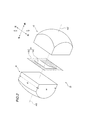
- FIG. 2 is an exploded perspective view of the optical system 44 constituting the microlens array 40.
- the optical system 44 shown in FIG. 2 includes an incident-side lens unit 41 having an optical axis Ax2, an emitting-side lens unit 42 having an optical axis Ax2', and a light-shielding plate 43.
- the optical axis Ax2 and the optical axis Ax2' may coincide with or deviate from each other.
- the optical axis Ax2 and the optical axis Ax2'are coincident (when the optical axis is common) the design of the microlens array 40 becomes easy.
- the optical axis Ax2 and the optical axis Ax2' are substantially parallel to the optical axis Ax1 shown in FIG.
- the incident side lens portion 41 is a portion where the light emitted from the exit surface 33 of the primary lens 30 is incident, and is formed so that, for example, the surface facing the exit surface 33 has a convex curved surface.
- the surface of the incident-side lens unit 41 facing the exit-side lens unit 42 is formed by a plane extending along the vertical plane orthogonal to the optical axis Ax2.
- the length (effective aperture) av of the incident side lens portion 41 in the vertical direction and the length (effective aperture) ah in the horizontal direction may be equal to or different from each other. From the viewpoint of facilitating the formation of a horizontally long light distribution pattern suitable for vehicle lighting equipment, it is preferable to make the length ah longer than the length av.
- the light-shielding plate 43 is provided between the incident side lens portion 41 and the outgoing side lens portion 42.
- the light-shielding plate 43 defines the shape of the projected image, and forms, for example, a cut-off line.
- the light-shielding plate 43 has an opening 43a and a light-shielding portion 43b. A part of the light incident on the incident side lens portion 41 is blocked by the light shielding portion 43b. The unblocked light passes through the opening 43a and is emitted forward from the exit-side lens portion 42.
- a part of the plurality of optical systems 44 constituting the microlens array 40 does not have to have the light-shielding plate 43. Further, when the cut-off line is not required, the microlens array 40 may be configured not to have the light-shielding plate 43. Further, the microlens array 40 may include a color filter for changing the color of the light emitted from the light source 20 between the incident side lens unit 41 and the emitting side lens unit 42.
- each of the plurality of optical systems 44 has a light-shielding plate 43
- the shape of each light-shielding plate 43 may be different or may be the same.
- the shapes of the light-shielding plates 43 are the same, it becomes easy to form a light distribution pattern for a low beam without excessively increasing the manufacturing difficulty and the manufacturing cost of the microlens array.
- the exit side lens unit 42 is a portion that emits the light incident from the incident side lens unit 41 in the forward direction.
- the front surface of the exit side lens portion 42 is formed so as to have a convex curved surface.
- the rear side surface (the surface facing the incident side lens unit 41) of the exit side lens portion 42 is formed of a plane extending along the vertical plane orthogonal to the optical axis Ax2'.
- the incident side lens portion 41 and the outgoing side lens portion 42 are configured so that the surfaces facing each other have the same shape.
- the incident side lens portion 41 and the outgoing side lens portion 42 are integrated with a light shielding plate 43 sandwiched between them.
- the microlens array 40 shown in FIG. 1 includes a plurality of the above optical systems 44, and each optical system 44 is arranged adjacent to each other in a direction intersecting the optical axis Ax1 (for example, in the horizontal direction and the vertical direction). It has an array-like structure that is integrated in a lined state).
- the shape of the microlens array 40 is not particularly limited, but is, for example, rectangular or circular in rear view.
- the incident-side focal length f'of the incident-side lens unit 41 in the optical system 44 differs depending on the position of the optical system 44.
- this point will be described in detail with reference to FIG.
- FIG. 3 is a schematic view showing the configuration of the vehicle lamp 10 according to the first embodiment.
- the microlens array 40 includes an optical system having an incident side lens portion 41a and an emitting side lens portion 42a (a portion on the left side of the imaginary line L1), an incident side lens portion 41b, and an emitting side lens.
- An optical system having a portion 42b (a portion between the imaginary lines L1 and L2) and an optical system having an incident side lens portion 41c and an emitting side lens portion 42c (a portion on the right side of the imaginary line L2) are provided.
- the microlens array 40 may include the above-mentioned light-shielding plate 43.
- the radius of curvature of each incident surface of the incident side lens portions 41a to 41c is the incident side lens portions 41a to 41c in ascending order. That is, the incident side focal length f'of the incident side lens portion 41a is the smallest, the incident side focal length f'of the incident side lens portion 41b is the next largest, and the incident side focal length f'of the incident side lens portion 41c is the largest. .. Due to these differences in the focal length f'on the incident side, the projected angle of view of the projected image projected forward of the vehicle lamp 10 is different. Therefore, a desired light distribution pattern can be formed by superimposing these projection images having different angles of view. The larger the incident-side focal length f'of the incident-side lens unit 41, the larger the projected angle of view.
- the sizes of the effective aperture ah1 of the incident side lens portion 41a, the effective aperture ah2 of the incident side lens portion 41b, and the effective aperture ah3 of the incident side lens portion 41c are substantially equal to each other.
- a desired light distribution pattern can be formed without changing the effective aperture of each incident side lens portion 41, so that the size of the microlens array 40 is suppressed from becoming large. It can contribute to space saving.
- the shapes of the lens portions 42a to 42c on the exit side are the same. That is, the sizes of the effective apertures of the emitting side lens portions 42a to 42c are substantially equal to each other. Similarly, the radii of curvature of the exit surfaces of the exit side lens portions 42a to 42c are also substantially equal to each other. With such a configuration, the microlens array 140 can be easily manufactured and the manufacturing cost can be suppressed.
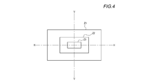
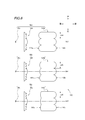
- FIG. 4 is a schematic diagram of a light distribution pattern formed by the vehicle lamp 10 according to the first embodiment.
- the region Z1 shown in FIG. 4 is a region where the light that has passed through the incident side lens portion 41c is irradiated.
- the region Z2 is a region to be irradiated with the light that has passed through the incident side lens portion 41c and the light that has passed through the incident side lens portion 41b.
- the region Z3 is a region to be irradiated with the light that has passed through the incident side lens portion 41c, the light that has passed through the incident side lens portion 41b, and the light that has passed through the incident side lens portion 41a.
- the light distribution pattern shown in FIG. 4 is a case where the influence of the light-shielding plate 43 is not taken into consideration.
- the microlens array 40 may have a plurality of types of incident-side focal lengths f', or the arrangement of each optical system in the microlens array 40 may be changed to make the microlens array 40 more diverse. It is also possible to form a light distribution pattern.
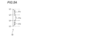
- the primary lens 50 shown in FIG. 5A is a so-called Fresnel lens.
- the focal length f of the part 51a (the part between the imaginary lines L3 and L4) is the part 51b (the part between the imaginary lines L4 and L5) and the part 51c (the part between the imaginary lines L2 and L3). ) Is a lens shorter than the focal length f.
- the focal length f of the part 61a (the part between the imaginary lines L3 and L4) is the part 61b (the part between the imaginary lines L4 and L5) and the part 61c (the part between the imaginary lines L2 and L3). It is a lens longer than the focal length f (the part between).
- the part 71a (the part between the imaginary lines L3 and L4), the part 71b (the part between the imaginary lines L4 and L5) and the part 71c (the part between the imaginary lines L2), in ascending order of the focal length f And the part between L3), the part 71d (the part below the imaginary line L5) and the part 71e (the part above the imaginary line L2).
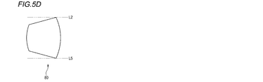
- the primary lens 80 shown in FIG. 5D is a so-called applanate lens, which is a collimated lens in which the focal length f with respect to the light source does not change in the lens.
- FIG. 6 is a schematic view showing a partial configuration of the vehicle lamp 110 according to the second embodiment.
- the vehicle lamp 110 includes optical units 90a to 90c.
- the optical unit 90a includes a light source 20a, a primary lens 50a, and a microlens array 140a on the optical axis Ax3.
- the optical unit 90b includes a light source 20b, a primary lens 50b, and a microlens array 140b on the optical axis Ax4.
- the optical unit 90c includes a light source 20c, a primary lens 50c, and a microlens array 140c on the optical axis Ax5.
- the light sources 20a to 20c can adopt the same configuration as the light source 20 in the first embodiment.
- the light sources 20a to 20c may be the same or different.
- the primary lenses 50a to 50c are Fresnel lenses shown in FIG. 5A.
- the primary lenses 50a to 50c may be the same or different.
- each optical system constituting the microlens array 140a is the same. That is, the incident surface of the microlens array 140a is composed of one type of incident side lens unit 141a, and the incident side focal length f'and the effective aperture ah4 of each incident side lens unit 141a are equal. Similarly, the microlens arrays 140b and 140c are each composed of one type of optical system.
- the incident side focal lengths f'of the incident side lens portions 141a to 141c are different in each optical system constituting them.
- the radius of curvature of each incident surface of the incident side lens portions 141a to 141c is from the incident side lens portions 141a to 141c in ascending order. That is, the incident side focal length f'of the incident side lens unit 141a is the smallest, the incident side focal length f'of the incident side lens unit 141b is the next largest, and the incident side focal length f'of the incident side lens unit 141c is the largest. ..
- the projected angle of view of the projected image projected forward of the vehicle lamp 110 is different for each of the optical units 90a to 90c. Therefore, a desired light distribution pattern can be formed by superimposing these projection images having different angles of view.
- the shapes of the lens portions 142a to 142c on the exit side are the same. That is, the sizes of the effective apertures of the emitting side lens portions 142a to 142c are substantially equal to each other. Similarly, the radii of curvature of the exit surfaces of the exit side lens portions 142a to 142c are also substantially equal to each other. With such a configuration, the microlens array 140 can be easily manufactured and the manufacturing cost can be suppressed.
- each microlens array 140a to 140c may be provided with a light-shielding plate. Further, with respect to the configuration not described above, the contents described in the first embodiment can be appropriately adopted as long as there is no contradiction.
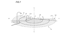
- FIG. 7 is an example of a light distribution pattern that can be formed by the vehicle lamp 10 or 110 of the present disclosure. Specifically, FIG. 7 is a diagram showing a low beam light distribution pattern Pt formed by applying a vehicle lighting tool 10 or 110 to a vehicle headlight and irradiating light from the headlight.
- the low beam light distribution pattern Pt is a left light distribution low beam light distribution pattern, and has cut-off lines CL1 and CL2 at the upper end edges thereof.
- the oncoming lane side portion on the right side of the VV line that passes through the HV, which is the extinguishing point in the front direction of the headlight, in the vertical direction is formed as a horizontal cut-off line CL1.
- the portion on the left side of the line on the own lane side is formed as a cut-off line CL2 in the diagonal direction.
- the elbow point E which is the intersection of the two, is located about 0.5 to 0.6 ° below the HV.
- the region Z1 in the low beam light distribution pattern Pt is, for example, a portion irradiated by the light having the largest projection angle of view, and has a lower luminous intensity than the regions Z2 and Z3.
- Region Z2 is, for example, a portion irradiated by light having the largest projected angle of view and light having the second largest projected angle of view, and has a lower luminous intensity than Z3.
- Region Z3 is, for example, a portion irradiated by light having the largest projected angle of view, light having the second largest projected angle of view, and light having the smallest projected angle of view, and has the highest luminous intensity in each region.
- the horizontal sectional view of the vehicle lamp 10 according to the third embodiment of the present disclosure may be the same as that shown in FIG.
- the exploded perspective view of the optical system 44 constituting the microlens array 40 may be the same as that shown in FIG.
- the vehicle lamp 10 according to the third embodiment will be described, but the matters described in the first embodiment will be omitted as appropriate.
- the effective aperture (length) av of the incident side lens unit 41 in the vertical direction (vertical direction) is shorter than the effective aperture (length) ah in the horizontal direction (horizontal direction). Further, the incident-side focal length f'in the vertical direction of the incident-side lens unit 41 is shorter than the incident-side focal length f'in the left-right direction.
- the plurality of optical systems 44 constituting the microlens array 40 may be the same or may include different ones.
- the plurality of incident side lens portions 41 in the plurality of optical systems 44 may all have the same shape (the effective diameter and the radius of curvature in each of the vertical direction and the horizontal direction are the same), or may have different shapes (vertical direction). And one or more elements of the effective diameter and the radius of curvature in each of the left and right directions are different).
- the plurality of incident side lens portions 41 include those having different shapes, for example, the plurality of incident side lens portions 41 have the same effective aperture in the vertical direction and the effective aperture in the horizontal direction. Is preferable, and it is more preferable that all the effective diameters in the vertical direction are the same. Such a configuration facilitates the manufacture of the microlens array 40.
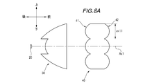
- FIG. 8A is a schematic view showing a configuration of the vehicle lamp 10 of the third embodiment in a vertical plane.
- FIG. 8B is a schematic view showing a configuration of the vehicle lamp 10 of the third embodiment in a horizontal plane.
- each incident side lens portion 41 constituting the microlens array 40 has an effective diameter and a radius of curvature of the incident surface in the vertical direction (vertical direction) and the horizontal direction (horizontal direction). It's different. Specifically, in each of the plurality of incident side lens portions 41 constituting the microlens array 44, the effective aperture ah11 in the left-right direction is larger than the effective aperture av11 in the up-down direction.
- the radius of curvature in the left-right direction is larger than the radius of curvature in the up-down direction. That is, the incident-side focal length f'of the incident-side lens unit 41 is larger in the horizontal direction than in the vertical direction.
- the projected angle of view of the projected image projected to the front of the vehicle lighting fixture 10 is different in the vertical direction and the horizontal direction.
- the larger the effective aperture the larger the projected angle of view, so that the projected angle of view in the left-right direction is larger than that in the vertical direction.
- the larger the incident-side focal length f' the larger the projected angle of view, so that the projected angle of view is larger in the left-right direction than in the up-down direction. Therefore, it is easier to form a projection image with a desired aspect ratio than controlling the projection angle of view with only one of the effective aperture and the focal length f'on the incident side, and the degree of freedom in optical design is increased. It is possible to increase it.
- the effective apertures of the emitting side lens unit 42 in the vertical direction and the horizontal direction are substantially equal to the effective apertures of the incident side lens unit 41 forming the optical system 44 together with the emitting side lens unit 42.
- the focal length on the exit side of the exit side lens unit 42 is not particularly limited, and can be appropriately determined according to other configurations of the vehicle lamp 10.
- the microlens array 40 may include the above-mentioned light-shielding plate 43.
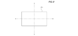
- FIG. 9 is a schematic view of a projected image formed by the vehicle lamp 10 of the third embodiment.
- the region Z11 is a region on which the projected image formed by the vehicle lamp 10 is projected.
- the projected image spreads in the direction of the HH line passing in the horizontal direction rather than the direction of the VV line passing in the vertical direction. Can be easily formed.
- the aspect ratio of the obtained projected image can be changed in the vertical direction and the horizontal direction by adjusting the effective aperture of the incident side lens unit 41 and / or the incident side focal length f'.
- Each lens shown in FIGS. 5A to 5D can also be applied as a primary lens of the vehicle lighting fixture 10 of the third embodiment.
- FIG. 10 is a schematic view showing the configuration of the microlens array 240 in this modified example.
- FIG. 10 is a schematic view of the microlens array 240 viewed from the light source 20 side.
- the microlens array 240 shown in FIG. 10 is used instead of the microlens array 40. Since the same configuration as that of the third embodiment can be adopted for other configurations, only the microlens array 240 will be described below.
- the microlens array 240 is composed of optical systems 244 (optical systems 244a to d) having a plurality of types of shapes. At the center of the microlens array 240 (near the optical axis Ax1), an optical system 244a having an incident side lens portion having the largest effective aperture ah in the left-right direction is arranged. Around the optical system 244a, optical systems 244b and 244c having an incident side lens portion having the second largest effective aperture ah in the left-right direction are arranged. Further, an optical system 244d having an incident side lens portion having the smallest effective aperture ah in the left-right direction is arranged above the optical system 244c. The optical system 244b and the optical system 244c have the same shape.
- crosstalk in the left-right direction is suppressed by arranging an optical system 244a having an incident side lens portion having the largest effective aperture ah in the left-right direction in the vicinity of the optical axis Ax1 where crosstalk is likely to occur. It's easy.
- the microlens array suppresses crosstalk in the left-right direction. It is possible to reduce the size of 240. Further, it is possible to form a light distribution pattern due to the difference in the effective aperture ah as described above.
- the effective aperture avs in the vertical direction in each of the incident side lens portions constituting each of the optical systems 244a to 244d are substantially the same. With such a configuration, the microlens array 240 can be easily manufactured.
- the vertical effective aperture av of the incident side lens portion is shorter than the horizontal effective aperture ah
- the vertical incident side focal length f'of the incident side lens portion is It is shorter than the focal length f'on the incident side in the left-right direction.
Landscapes
- Engineering & Computer Science (AREA)
- General Engineering & Computer Science (AREA)
- Physics & Mathematics (AREA)
- Optics & Photonics (AREA)
- Microelectronics & Electronic Packaging (AREA)
- Non-Portable Lighting Devices Or Systems Thereof (AREA)
Abstract
車両用灯具は、光源(20)と、プライマリレンズ(30)と、光源(20)から出射された光がプライマリレンズ(30)を介して入射されるマイクロレンズアレイ(40)と、を備えている。マイクロレンズアレイ(40)は、複数の光学系を有し、複数の光学系はそれぞれ、共通の光軸上に設けられた入射側レンズ部(41a~41c)と出射側レンズ部(42a~42c)とを有し、複数の光学系が有する複数の入射側レンズ部(41a~41c)には、焦点距離が異なる少なくとも2種以上の入射側レンズ部が含まれ、かつ、少なくとも2種以上の入射側レンズ部それぞれの有効口径は同一である。
Description
本開示は、車両用灯具に関する。
特許文献1~2などにより、マイクロレンズアレイ(以下、「MLA」とも称する)を用いた車両用灯具が提案されている。特許文献1では、MLAに遮光体を設けて光源から出射された光の一部を遮ることにより、車両用灯具の配光パターンを形成することが提案されている。また、特許文献2では、有効口径の異なるマイクロレンズを複数用いることにより、配光パターンを形成することが提案されている。
また、特許文献1では、MLAに遮光体を設けて光源から出射された光の一部を遮ることにより、所定のアスペクト比を有する投影像を形成することが提案されている。また、特許文献2では、MLAの有効口径が縦横方向のそれぞれで異なるように制御することにより、所定のアスペクト比を有する投影像を形成することが提案されている。
本開示は、新たな構成により所望の配光パターンを形成可能な車両用灯具を提供することを第一の課題とする。
本開示は、新たな構成により所望のアスペクト比を有する投影像を形成可能な車両用灯具を提供することを第二の課題とする。
上記第一の課題を解決するために、本開示の一態様に係る車両用灯具は、
光源と、
プライマリレンズと、
前記光源から出射された光が前記プライマリレンズを介して入射されるマイクロレンズアレイと、を備えた車両用灯具であって、
前記マイクロレンズアレイは、複数の光学系を有し、
前記複数の光学系はそれぞれ、一対に設けられた入射側レンズ部と出射側レンズ部とを有し、
前記複数の光学系が有する複数の前記入射側レンズ部には、焦点距離が異なる少なくとも2種以上の入射側レンズ部が含まれ、かつ、前記少なくとも2種以上の入射側レンズ部それぞれの有効口径は同一である。
光源と、
プライマリレンズと、
前記光源から出射された光が前記プライマリレンズを介して入射されるマイクロレンズアレイと、を備えた車両用灯具であって、
前記マイクロレンズアレイは、複数の光学系を有し、
前記複数の光学系はそれぞれ、一対に設けられた入射側レンズ部と出射側レンズ部とを有し、
前記複数の光学系が有する複数の前記入射側レンズ部には、焦点距離が異なる少なくとも2種以上の入射側レンズ部が含まれ、かつ、前記少なくとも2種以上の入射側レンズ部それぞれの有効口径は同一である。
この構成によれば、所望の配光パターンを形成可能になる。
また、上記第一の課題を解決するために、本開示の一態様に係る車両用灯具は、
光源と、
プライマリレンズと、
前記光源から出射された光が前記プライマリレンズを介して入射されるマイクロレンズアレイと、を有する光学ユニットを複数備えた車両用灯具であって、
前記マイクロレンズアレイは、複数の光学系を有し、
前記複数の光学系はそれぞれ、一対に設けられた入射側レンズ部と出射側レンズ部とを有し、
前記入射側レンズ部は、前記マイクロレンズアレイ毎に同一の形状を有しており、
複数の前記光学ユニットが有する複数の前記マイクロレンズアレイには、前記入射側レンズ部の焦点距離が異なる少なくとも2種以上のマイクロレンズアレイが含まれ、かつ、前記少なくとも2種以上のマイクロレンズアレイ間において前記入射側レンズ部の有効口径が同一である。
光源と、
プライマリレンズと、
前記光源から出射された光が前記プライマリレンズを介して入射されるマイクロレンズアレイと、を有する光学ユニットを複数備えた車両用灯具であって、
前記マイクロレンズアレイは、複数の光学系を有し、
前記複数の光学系はそれぞれ、一対に設けられた入射側レンズ部と出射側レンズ部とを有し、
前記入射側レンズ部は、前記マイクロレンズアレイ毎に同一の形状を有しており、
複数の前記光学ユニットが有する複数の前記マイクロレンズアレイには、前記入射側レンズ部の焦点距離が異なる少なくとも2種以上のマイクロレンズアレイが含まれ、かつ、前記少なくとも2種以上のマイクロレンズアレイ間において前記入射側レンズ部の有効口径が同一である。
この構成によれば、所望の配光パターンを形成可能になる。
上記第二の課題を解決するために、本開示の一態様に係る車両用灯具は、
光源と、
プライマリレンズと、
前記光源から出射された光が前記プライマリレンズを介して入射されるマイクロレンズアレイと、を備えた車両用灯具であって、
前記マイクロレンズアレイは、複数の光学系を有し、
前記複数の光学系はそれぞれ、一対に設けられた入射側レンズ部と出射側レンズ部とを有し、
前記複数の光学系は、前記入射側レンズ部の出射方向に直交する第1方向、及び、前記出射方向と前記第1方向とに直交する第2方向に沿って並列して一体化されており、
前記複数の光学系における複数の入射側レンズ部の各々は、
前記第1方向における有効口径が前記第2方向における有効口径よりも短く、かつ、
前記第1方向における焦点距離が前記第2方向における焦点距離よりも短い。
光源と、
プライマリレンズと、
前記光源から出射された光が前記プライマリレンズを介して入射されるマイクロレンズアレイと、を備えた車両用灯具であって、
前記マイクロレンズアレイは、複数の光学系を有し、
前記複数の光学系はそれぞれ、一対に設けられた入射側レンズ部と出射側レンズ部とを有し、
前記複数の光学系は、前記入射側レンズ部の出射方向に直交する第1方向、及び、前記出射方向と前記第1方向とに直交する第2方向に沿って並列して一体化されており、
前記複数の光学系における複数の入射側レンズ部の各々は、
前記第1方向における有効口径が前記第2方向における有効口径よりも短く、かつ、
前記第1方向における焦点距離が前記第2方向における焦点距離よりも短い。
この構成によれば、所望のアスペクト比を有する投影像を形成可能になる。
本開示の一態様によれば、新たな構成により所望の配光パターンを形成可能な車両用灯具を提供することができる。
また、本開示の一態様によれば、新たな構成により所望のアスペクト比を有する投影像を形成可能な車両用灯具を提供することができる。
以下、本開示に係る車両用灯具の実施の形態の例を、図面を参照しつつ説明する。以下の説明では、異なる図面であっても同一又は相当の要素には同一の符号を付し、重複する説明を適宜省略する。また、以下の説明に用いる各図面では、各部材を認識可能な大きさとするために縮尺を適宜変更している。
なお、本明細書において、「左右方向」、「前後方向」、「上下方向」とは、本開示に係る車両用灯具について、説明の便宜上、設定された相対的な方向である。「前後方向」とは、「前方向」および「後方向」を含む方向である。「左右方向」とは、「左方向」および「右方向」を含む方向である。「上下方向」とは、「上方向」および「下方向」を含む方向である。
本開示に係る車両用灯具を車両用前照灯として用いる場合、車両用灯具における「前後方向」、「左右方向」、及び「上下方向」は、車両における「前後方向」、「左右方向」、及び「上下方向」とそれぞれ一致する。なお、以下の説明において、「左右方向」を「水平方向」と称することもある。同様に、「上下方向」を「垂直方向」と称することもある。また、本明細書では、車両用灯具の水平方向における構成を主に説明するが、水平方向における各構成は、垂直方向においても適用可能である。
[第一実施形態]
図1は、本開示の第一実施形態に係る車両用灯具10の水平断面図である。図1に示すように、車両用灯具10は、ランプボディ11及び透光カバー12によって形成される灯室内に、光源20と、プライマリレンズ30と、マイクロレンズアレイ40と、を備えた構成となっている。
図1は、本開示の第一実施形態に係る車両用灯具10の水平断面図である。図1に示すように、車両用灯具10は、ランプボディ11及び透光カバー12によって形成される灯室内に、光源20と、プライマリレンズ30と、マイクロレンズアレイ40と、を備えた構成となっている。
光源20は、ランプボディ11によって支持される基板21に搭載された状態で、前方向へ向けて配置されている。光源20から出射される光は、プライマリレンズ30及びマイクロレンズアレイ40を通過して、車両用灯具10の前方向へと出射される。
光源20は、例えば、白色発光ダイオード又は半導体レーザである。光源20は、例えば、矩形状(例えば、正方形や長方形)の発光面を有している。発光面の形状として長方形を採用した場合、車両用灯具に適した横長の配光パターンを形成することが容易になる。
プライマリレンズ30は、光源20に対して第1焦点距離f1を有する第1部位31aと、光源20に対して第1焦点距離f1よりも長い第2焦点距離f2を有する第2部位31b及び31cとを有している。これらの焦点距離の違いにより、第1部位31aからマイクロレンズアレイ40へ向けて出射される平行光と、第2部位31b及び31cからマイクロレンズアレイ40へ向けて出射される平行光とでは、マイクロレンズアレイ40を介して投影される投影像の投影画角が異なることになる。そのため、これら画角の異なる投影像を重ね合わせることにより、所望の配光パターンを形成できる。プライマリレンズ30における光源20に対する焦点距離が小さいほど、投影画角が大きくなる。
なお、後述するように、車両用灯具10は、マイクロレンズアレイ40の作用によって、所望の配光パターンを形成可能である。プライマリレンズ30の上記構成および以下で説明する構成は、好ましい構成であって、必須の構成ではない。例えば、プライマリレンズ30として、光源に対する焦点距離fがレンズ内で変化せずに一定のコリメートレンズ(例えば、アプラナートレンズ)を用いてもよい。
プライマリレンズ30は、光源20に対する焦点距離(以下、「焦点距離f」とも称する)がレンズ内で変化するコリメートレンズである。プライマリレンズ30は、例えば、3種類以上の焦点距離fを有する構成であってもよい。また、プライマリレンズ30は、焦点距離fが光軸Ax1からの距離等に応じて連続的に変化するよう構成してもよいし、不連続的に変化するよう構成してもよい。プライマリレンズ30の各部位における焦点距離fは、例えば、その部位と光源20との距離に応じたものとすることが好ましい。プライマリレンズ30は、光源20に近接して配置されていてもよく、光源20から一定の距離を置いて配置されていてもよい。
プライマリレンズ30は、光源20からの光を入射させる入射面32a~32cと、入射面32a~32cから入射した光をマイクロレンズアレイ40へ向けて出射させる出射面33とを備えている。プライマリレンズ30の形状は、特に制限はされないが、例えば、後方視において円形状である。プライマリレンズ30は、出射面33の外周部に形成されるフランジ部34において、ランプボディ11に支持される。
入射面32aは、光源20の発光中心を通るようにして前後方向に延びる光軸Ax1を中心とする回転曲面で構成されている。入射面32aから入射する光は、例えば、入射面32aにおいて屈折し、光軸Ax1に略平行な光となって、出射面33から出射される。
入射面32bから入射する光は、例えば、光軸Ax1から離れる方向に向けて進んだ後、第2部位31bの周辺領域において全反射によって内面反射し、光軸Ax1と略平行な光となって、出射面33から出射される。入射面32cから入射する光も、上記と同様である。
出射面33は、光軸Ax1と直交する鉛直面に沿って延びる平面で構成されている。出射面33は、例えば、入射面32a~32cから入射した光を光軸Ax1と平行な光としてマイクロレンズアレイ40へ向けて出射する。
マイクロレンズアレイ40は、複数の光学系によって構成されている。図2は、マイクロレンズアレイ40を構成する光学系44の分解斜視図である。図2に示す光学系44は、光軸Ax2を有する入射側レンズ部41と、光軸Ax2’を有する出射側レンズ部42と、遮光板43とを備えている。光軸Ax2と光軸Ax2’は一致してもよいし、ずれていてもよい。光軸Ax2と光軸Ax2’は一致している場合(光軸が共通の場合)、マイクロレンズアレイ40の設計が容易になる。光軸Ax2と光軸Ax2’は、図1に示す光軸Ax1に略平行である。
入射側レンズ部41は、プライマリレンズ30の出射面33から出射された光が入射する部位であり、例えば、出射面33に対向する面が凸曲面を有するように形成されている。一方で、入射側レンズ部41における出射側レンズ部42と対向する面は、光軸Ax2と直交する鉛直面に沿って延びる平面で構成されている。
入射側レンズ部41の垂直方向における長さ(有効口径)avと、水平方向における長さ(有効口径)ahとは、互いに等しくてもよいし、異なっていてもよい。車両用灯具に適した横長の配光パターンを形成することを容易にするという観点からは、長さavよりも長さahを長くすることが好ましい。
遮光板43は、入射側レンズ部41と出射側レンズ部42との間に設けられている。遮光板43は、投影像の形状を規定するものであり、例えば、カットオフラインを形成するものである。遮光板43は、開口部43aと、遮光部43bとを有している。入射側レンズ部41に入射した光は、その一部が遮光部43bによって遮られる。遮られなかった光は、開口部43aを通過して、出射側レンズ部42から前方向へと出射される。
マイクロレンズアレイ40を構成する複数の光学系44のうちの一部は、遮光板43を有していなくてもよい。また、カットオフラインを必要としない場合等は、マイクロレンズアレイ40は、遮光板43を有さないように構成してもよい。また、マイクロレンズアレイ40は、入射側レンズ部41と出射側レンズ部42との間に、光源20から出射された光の色を変更するためのカラーフィルタを備えていてもよい。
また、複数の光学系44それぞれが遮光板43を有する場合、各遮光板43の形状は、異なっていてもよいし、同一の形状であってもよい。各遮光板43の形状を同一の形状とした場合、マイクロレンズアレイの製造難度や製造コストを過度に上昇させることなく、ロービーム用の配光パターン等を形成することが容易になる。
出射側レンズ部42は、入射側レンズ部41から入射した光を前方向へ向けて出射する部位である。出射側レンズ部42における前方向側の面は、凸曲面を有するように形成されている。一方で、出射側レンズ部42における後方向側の面(入射側レンズ部41と対向する面)は、光軸Ax2’と直交する鉛直面に沿って延びる平面で構成されている。
入射側レンズ部41と、出射側レンズ部42とは、互いに対向する面同士が同一形状を有するように構成されている。入射側レンズ部41と、出射側レンズ部42とは、互いの間に遮光板43を挟んだ状態で一体化されている。
図1に示すマイクロレンズアレイ40は、上記の光学系44を複数備えており、各々の光学系44が光軸Ax1に交差する方向に隣接して並んだ状態(例えば、左右方向および上下方向に並んだ状態)で一体化したアレイ状の構造を有している。マイクロレンズアレイ40の形状は、特に制限はされないが、例えば、後方視において矩形状または円形状である。
図1では示していないが、本実施形態において、光学系44における入射側レンズ部41の入射側焦点距離f’は、その光学系44の位置に応じて異なっている。以下、この点について、図3を用いて詳述する。
図3は、第一実施形態に係る車両用灯具10の構成を示す模式図である。図3に示すように、マイクロレンズアレイ40は、入射側レンズ部41a及び出射側レンズ部42aを有する光学系(想像線L1の左方向側の部分)と、入射側レンズ部41b及び出射側レンズ部42bを有する光学系(想像線L1及びL2の間の部分)と、入射側レンズ部41c及び出射側レンズ部42cを有する光学系(想像線L2の右方向側の部分)と、を備えている。なお、図3では遮光板を図示していないが、マイクロレンズアレイ40は、上述した遮光板43を備えていてもよい。
入射側レンズ部41a~41cの各入射面の曲率半径は、小さい順から、入射側レンズ部41a~41cとなっている。すなわち、入射側レンズ部41aの入射側焦点距離f’が最も小さく、入射側レンズ部41bの入射側焦点距離f’が次に大きく、入射側レンズ部41cの入射側焦点距離f’が最も大きい。これらの入射側焦点距離f’の違いにより、車両用灯具10の前方へと投影される投影像の投影画角を異ならせている。そのため、これら画角の異なる投影像を重ね合わせることにより、所望の配光パターンを形成できる。なお、入射側レンズ部41の入射側焦点距離f’が大きいほど、投影画角が大きくなる。
一方で、入射側レンズ部41aの有効口径ah1、入射側レンズ部41bの有効口径ah2、及び入射側レンズ部41cの有効口径ah3の大きさは、互いに略等しくなっている。本実施形態に係る車両用灯具10によれば、各入射側レンズ部41の有効口径を変えなくとも所望の配光パターンを形成可能になるので、マイクロレンズアレイ40のサイズが大きくなることを抑制でき、省スペース性に寄与できる。
また、出射側レンズ部42a~42cそれぞれの形状は同一である。すなわち、出射側レンズ部42a~42cの各有効口径の大きさは、互いに略等しくなっている。同様に、出射側レンズ部42a~42cの各出射面の曲率半径も、互いに略等しくなっている。このような構成により、マイクロレンズアレイ140を製造し易くし、製造コストを抑えることを可能にしている。
図4は、第一実施形態に係る車両用灯具10によって形成される配光パターンの模式図である。図4に示す領域Z1は、入射側レンズ部41cを通過した光が照射される領域である。領域Z2は、入射側レンズ部41cを通過した光、および入射側レンズ部41bを通過した光が照射される領域である。領域Z3は、入射側レンズ部41cを通過した光、入射側レンズ部41bを通過した光、および入射側レンズ部41aを通過した光が照射される領域である。なお、図4に示す配光パターンは、遮光板43の影響を考慮しない場合のものである。
車両用灯具10において、例えば、マイクロレンズアレイ40を更に複数種類の入射側焦点距離f’を有するものにしたり、マイクロレンズアレイ40における各光学系の配置を変更したりすることで、更に多様な配光パターンを形成することも可能である。
図5A~図5Dは、本開示の車両用灯具10に適用可能なプライマリレンズの一例である。図5Aに示すプライマリレンズ50は、いわゆるフレネルレンズである。プライマリレンズ50は、部位51a(想像線L3及びL4の間の部位)の焦点距離fが、部位51b(想像線L4及びL5の間の部位)及び部位51c(想像線L2及びL3の間の部位)の焦点距離fよりも短いレンズである。
図5Bに示すプライマリレンズ60は、部位61a(想像線L3及びL4の間の部位)の焦点距離fが、部位61b(想像線L4及びL5の間の部位)及び部位61c(想像線L2及びL3の間の部位)の焦点距離fよりも長いレンズである。
図5Cに示すプライマリレンズ70では、焦点距離fが短い順に、部位71a(想像線L3及びL4の間の部位)、部位71b(想像線L4及びL5の間の部位)及び部位71c(想像線L2及びL3の間の部位)、部位71d(想像線L5の下の部位)及び部位71e(想像線L2の上の部位)となっている。
図5Dに示すプライマリレンズ80は、いわゆるアプラナートレンズであり、光源に対する焦点距離fがレンズ内で変化せずに一定のコリメートレンズである。
[第二実施形態]
本開示の第二実施形態に係る車両用灯具は、複数の光学ユニットから構成される。図6は、第二実施形態に係る車両用灯具110の一部の構成を示す模式図である。図6に示すように、車両用灯具110は、光学ユニット90a~90cを備えている。光学ユニット90aは、光源20aと、プライマリレンズ50aと、マイクロレンズアレイ140aとを光軸Ax3上に備えている。光学ユニット90bは、光源20bと、プライマリレンズ50bと、マイクロレンズアレイ140bとを光軸Ax4上に備えている。光学ユニット90cは、光源20cと、プライマリレンズ50cと、マイクロレンズアレイ140cとを光軸Ax5上に備えている。
本開示の第二実施形態に係る車両用灯具は、複数の光学ユニットから構成される。図6は、第二実施形態に係る車両用灯具110の一部の構成を示す模式図である。図6に示すように、車両用灯具110は、光学ユニット90a~90cを備えている。光学ユニット90aは、光源20aと、プライマリレンズ50aと、マイクロレンズアレイ140aとを光軸Ax3上に備えている。光学ユニット90bは、光源20bと、プライマリレンズ50bと、マイクロレンズアレイ140bとを光軸Ax4上に備えている。光学ユニット90cは、光源20cと、プライマリレンズ50cと、マイクロレンズアレイ140cとを光軸Ax5上に備えている。
光源20a~20cは、第一実施形態における光源20と同様の構成を採用できる。光源20a~20cは、それぞれ同一であっても、異なっていてもよい。プライマリレンズ50a~50cは、図5Aに示すフレネルレンズである。プライマリレンズ50a~50cは、それぞれ同一であっても、異なっていてもよい。
マイクロレンズアレイ140aを構成する各光学系は、全て同一である。すなわち、マイクロレンズアレイ140aの入射面は、1種類の入射側レンズ部141aで構成されており、各入射側レンズ部141aの入射側焦点距離f’及び有効口径ah4は等しい。同様に、マイクロレンズアレイ140b及び140cも、それぞれ1種類の光学系により構成されている。
一方で、マイクロレンズアレイ140a~140c間で比較すると、それらを構成する各光学系は、入射側レンズ部141a~141cの入射側焦点距離f’が異なっている。入射側レンズ部141a~141cにおける各入射面における曲率半径は、小さい順から、入射側レンズ部141a~141cとなっている。すなわち、入射側レンズ部141aの入射側焦点距離f’が最も小さく、入射側レンズ部141bの入射側焦点距離f’が次に大きく、入射側レンズ部141cの入射側焦点距離f’が最も大きい。これらの入射側焦点距離f’の違いにより、車両用灯具110の前方へと投影される投影像の投影画角を光学ユニット90a~90c毎に異ならせている。そのため、これら画角の異なる投影像を重ね合わせることにより、所望の配光パターンを形成できる。なお、入射側レンズ部141の入射側焦点距離f’が大きいほど、投影画角が大きくなる。
また、出射側レンズ部142a~142cそれぞれの形状は同一である。すなわち、出射側レンズ部142a~142cの各有効口径の大きさは、互いに略等しくなっている。同様に、出射側レンズ部142a~142cの各出射面の曲率半径も、互いに略等しくなっている。このような構成により、マイクロレンズアレイ140を製造し易くし、製造コストを抑えることを可能にしている。
なお、図6では遮光板を図示していないが、各マイクロレンズアレイ140a~140cは、遮光板を備えていてもよい。また、上記で説明していない構成については、第一実施形態で説明した内容を矛盾が生じない範囲で適宜採用することができる。
図7は、本開示の車両用灯具10又は110によって形成可能な配光パターンの一例である。図7は、具体的には、車両用灯具10又は110を車両用の前照灯に適用し、当該前照灯からの照射光によって形成したロービーム用配光パターンPtを示した図である。
ロービーム用配光パターンPtは、左配光のロービーム用配光パターンであって、その上端縁にカットオフラインCL1及びCL2を有している。具体的には、前照灯の正面方向の消点であるH-Vを鉛直方向に通るV-V線よりも右側の対向車線側部分が水平方向のカットオフラインCL1として形成され、V-V線よりも左側の自車線側部分が斜め方向のカットオフラインCL2として形成されている。また、両者の交点であるエルボ点Eは、H-Vの0.5~0.6°程度下方に位置している。
ロービーム用配光パターンPtにおける領域Z1は、例えば、投影画角が最も大きい光によって照射される部分であり、領域Z2及びZ3よりも光度が低い。領域Z2は、例えば、投影画角が最も大きい光および投影画角が二番目に大きい光によって照射される部分であり、Z3よりも光度が低い。領域Z3は、例えば、投影画角が最も大きい光、投影画角が二番目に大きい光、及び投影画角が最も小さい光によって照射される部分であり、各領域の中で最も光度が高い。
[第三実施形態]
本開示の第三実施形態に係る車両用灯具10の水平断面図は、図1に示すものと同様であってよい。本開示の第三実施形態において、マイクロレンズアレイ40を構成する光学系44の分解斜視図は、図2に示すものと同様であってよい。以下、第三実施形態に係る車両用灯具10について説明するが、第一実施形態において説明した事項については適宜省略する。
本開示の第三実施形態に係る車両用灯具10の水平断面図は、図1に示すものと同様であってよい。本開示の第三実施形態において、マイクロレンズアレイ40を構成する光学系44の分解斜視図は、図2に示すものと同様であってよい。以下、第三実施形態に係る車両用灯具10について説明するが、第一実施形態において説明した事項については適宜省略する。
入射側レンズ部41の上下方向(垂直方向)における有効口径(長さ)avは、左右方向(水平方向)における有効口径(長さ)ahよりも短い。また、入射側レンズ部41の上下方向における入射側焦点距離f’は、左右方向における入射側焦点距離f’よりも短い。これらの構成については、後の段落にて図8A及び8Bを用いて詳述する。
マイクロレンズアレイ40を構成する複数の光学系44は、同一のものであってもよいし、異なるものを含んでいてもよい。例えば、複数の光学系44における複数の入射側レンズ部41は、全て同一の形状(上下方向および左右方向のそれぞれにおける有効口径および曲率半径が同一)であってもよいし、異なる形状(上下方向および左右方向のそれぞれにおける有効口径および曲率半径のうち1以上の要素が異なる)のものを含んでいてもよい。
なお、複数の入射側レンズ部41が互いに異なる形状のものを含む場合、複数の入射側レンズ部41は、例えば、上下方向の有効口径および左右方向の有効口径のどちらかが全て同一であることが好ましく、上下方向の有効口径が全て同一であることがより好ましい。このような構成により、マイクロレンズアレイ40を製造し易くなる。
図8Aは、第三実施形態の車両用灯具10の鉛直面における構成を示す模式図である。図8Bは、第三実施形態の車両用灯具10の水平面における構成を示す模式図である。図8A及び図8Bに示すように、マイクロレンズアレイ40を構成する各入射側レンズ部41は、上下方向(垂直方向)と左右方向(水平方向)とにおいて、有効口径および入射面の曲率半径が異なっている。具体的には、マイクロレンズアレイ44を構成する複数の入射側レンズ部41の各々において、左右方向の有効口径ah11が、上下方向の有効口径av11よりも大きくなっている。また、入射側レンズ部41の各々において、左右方向の曲率半径が、上下方向の曲率半径よりも大きくなっている。すなわち、入射側レンズ部41の入射側焦点距離f’は、上下方向よりも左右方向において大きくなっている。
本実施形態においては、これらの構成により、車両用灯具10の前方へと投影される投影像の投影画角を、上下方向と左右方向とで異ならせている。具体的には、有効口径が大きいほど投影画角が大きくなるので、左右方向では上下方向よりも投影画角が大きくなる。同様に、入射側焦点距離f’が大きいほど投影画角が大きくなるので、左右方向では上下方向よりも投影画角が大きくなる。よって、有効口径および入射側焦点距離f’のどちらか一方のみで投影画角を制御するよりも、所望のアスペクト比を有する投影像を形成し易くなっており、光学的な設計の自由度を高めることが可能になっている。
出射側レンズ部42の上下方向および左右方向におけるそれぞれの有効口径は、当該出射側レンズ部42とともに光学系44を形成する入射側レンズ部41の各有効口径と略等しい。出射側レンズ部42の出射側焦点距離は、特に制限されず、車両用灯具10における他の構成に応じて、適宜決定することができる。なお、図8A及び図8Bでは遮光板43を図示していないが、マイクロレンズアレイ40は、上述した遮光板43を備えていてもよい。
図9は、第三実施形態の車両用灯具10によって形成される投影像の模式図である。領域Z11は、車両用灯具10によって形成される投影像が投影される領域である。図9に示すように、本実施形態に係る車両用灯具10によれば、鉛直方向に通るV-V線の方向よりも、水平方向に通るH-H線の方向の方に広がった投影像が容易に形成可能である。なお、得られる投影像のアスペクト比は、垂直方向と水平方向とにおいて、入射側レンズ部41の有効口径および/または入射側焦点距離f’を調整することで変更可能である。
図5A~図5Dに示した各レンズは、第三実施形態の車両用灯具10のプライマリレンズとしても適用可能である。
[第三実施形態の変形例]
以下、第三実施形態の車両用灯具10の変形例を説明する。図10は、本変形例におけるマイクロレンズアレイ240の構成を示す模式図である。図10は、具体的には、マイクロレンズアレイ240を光源20側から視た場合の模式図である。本変形例では、マイクロレンズアレイ40に代えて、図10に示すマイクロレンズアレイ240を用いる。その他の構成は、第三実施形態と同一の構成を採用できるため、以下では、マイクロレンズアレイ240についてのみ説明する。
以下、第三実施形態の車両用灯具10の変形例を説明する。図10は、本変形例におけるマイクロレンズアレイ240の構成を示す模式図である。図10は、具体的には、マイクロレンズアレイ240を光源20側から視た場合の模式図である。本変形例では、マイクロレンズアレイ40に代えて、図10に示すマイクロレンズアレイ240を用いる。その他の構成は、第三実施形態と同一の構成を採用できるため、以下では、マイクロレンズアレイ240についてのみ説明する。
マイクロレンズアレイ240は、複数種類の形状の光学系244(光学系244a~d)から構成されている。マイクロレンズアレイ240の中央部(光軸Ax1の近傍)には、左右方向の有効口径ahが最も大きい入射側レンズ部を有する光学系244aが配置されている。光学系244aの周囲には、左右方向の有効口径ahが2番目に大きい入射側レンズ部を有する光学系244b及び244cが配置されている。また、光学系244cの上部には、左右方向の有効口径ahが最も小さい入射側レンズ部を有する光学系244dが配置されている。なお、光学系244bと光学系244cとは、同一形状のものである。
一般的に、光軸Ax1近傍の焦点距離が短いプライマリレンズを用いた場合、光軸Ax1の近傍ではクロストークが発生し易く、光軸Ax1から離れるにつれてクロストークが発生しにくくなる。本変形例では、クロストークが発生し易い光軸Ax1の近傍に、左右方向の有効口径ahが最も大きい入射側レンズ部を有する光学系244aを配置することで、左右方向におけるクロストークを抑制し易くしている。また、光軸Axから離れるにつれ、そこに配置される光学系244の入射側レンズ部の有効口径ahが小さくなるように構成しているので、左右方向におけるクロストークを抑制しつつ、マイクロレンズアレイ240を小型化することが可能である。さらに、上記のような有効口径ahの違いにより、配光パターンを形成することも可能になっている。
また、光学系244a~244dのそれぞれを構成する入射側レンズ部の各々における上下方向の有効口径avは、全て略同一になっている。このような構成により、マイクロレンズアレイ240を製造し易くすることができる。
なお、マイクロレンズアレイ240における上記以外の構成は、第三実施形態と同一の構成を採用できる。例えば、光学系244a~244dの各々において、入射側レンズ部の上下方向の有効口径avは左右方向の有効口径ahよりも短く、かつ、入射側レンズ部の上下方向の入射側焦点距離f’は左右方向の入射側焦点距離f’よりも短くなっている。
以上、本開示を詳細にまた特定の実施態様を参照して説明したが、本発明の精神と範囲を逸脱することなく様々な変更や修正を加えることができることは当業者にとって明らかである。また、上記説明した構成部材の数、位置、形状等は上記実施の形態に限定されず、本開示を実施する上で好適な数、位置、形状等に変更することができる。
本出願は、2019年9月24日出願の日本特許出願2019-173250号、及び日本特許出願2019-173251号に基づくものであり、その内容はここに参照として取り込まれる。
Claims (10)
- 光源と、
プライマリレンズと、
前記光源から出射された光が前記プライマリレンズを介して入射されるマイクロレンズアレイと、を備えた車両用灯具であって、
前記マイクロレンズアレイは、複数の光学系を有し、
前記複数の光学系はそれぞれ、一対に設けられた入射側レンズ部と出射側レンズ部とを有し、
前記複数の光学系が有する複数の前記入射側レンズ部には、焦点距離が異なる少なくとも2種以上の入射側レンズ部が含まれ、かつ、前記少なくとも2種以上の入射側レンズ部それぞれの有効口径は同一である、
車両用灯具。 - 前記複数の光学系が有する複数の前記出射側レンズ部それぞれの形状は同一である、
請求項1に記載の車両用灯具。 - 前記複数の光学系のうち少なくとも2以上の光学系はそれぞれ、前記入射側レンズ部と前記出射側レンズ部との間に遮光体を有しており、
前記少なくとも2以上の光学系それぞれが有する前記遮光体の形状が同一である、
請求項1または請求項2に記載の車両用灯具。 - 光源と、
プライマリレンズと、
前記光源から出射された光が前記プライマリレンズを介して入射されるマイクロレンズアレイと、を有する光学ユニットを複数備えた車両用灯具であって、
前記マイクロレンズアレイは、複数の光学系を有し、
前記複数の光学系はそれぞれ、一対に設けられた入射側レンズ部と出射側レンズ部とを有し、
前記入射側レンズ部は、前記マイクロレンズアレイ毎に同一の形状を有しており、
複数の前記光学ユニットが有する複数の前記マイクロレンズアレイには、前記入射側レンズ部の焦点距離が異なる少なくとも2種以上のマイクロレンズアレイが含まれ、かつ、前記少なくとも2種以上のマイクロレンズアレイ間において前記入射側レンズ部の有効口径が同一である、
車両用灯具。 - 前記少なくとも2種以上のマイクロレンズアレイ間において前記出射側レンズ部の形状が同一である、
請求項4に記載の車両用灯具。 - 前記少なくとも2種以上のマイクロレンズアレイそれぞれにおける少なくとも一部の光学系は、前記入射側レンズ部と前記出射側レンズ部との間に遮光体を有しており、
前記少なくとも2種以上の前記マイクロレンズアレイそれぞれが有する前記遮光体の形状が同一である、
請求項4または請求項5に記載の車両用灯具。 - 光源と、
プライマリレンズと、
前記光源から出射された光が前記プライマリレンズを介して入射されるマイクロレンズアレイと、を備えた車両用灯具であって、
前記マイクロレンズアレイは、複数の光学系を有し、
前記複数の光学系はそれぞれ、一対に設けられた入射側レンズ部と出射側レンズ部とを有し、
前記複数の光学系は、前記入射側レンズ部の出射方向に直交する第1方向、及び、前記出射方向と前記第1方向とに直交する第2方向に沿って並列して一体化されており、
前記複数の光学系における複数の入射側レンズ部の各々は、
前記第1方向における有効口径が前記第2方向における有効口径よりも短く、かつ、
前記第1方向における焦点距離が前記第2方向における焦点距離よりも短い、
車両用灯具。 - 前記複数の入射側レンズ部は、前記第1方向における有効口径がそれぞれ略同一であり、かつ、前記第2方向における有効口径が互いに異なるものを含む、
請求項7に記載の車両用灯具。 - 前記第2方向における有効口径が最も大きい入射側レンズ部を有する光学系が、前記マイクロレンズアレイの中央部に位置する、
請求項8に記載の車両用灯具。 - 前記一対に設けられた前記入射側レンズ部と前記出射側レンズ部は、共通の光軸上に設けられている、
請求項1から請求項9のいずれか一項に記載の車両用灯具。
Priority Applications (1)
| Application Number | Priority Date | Filing Date | Title |
|---|---|---|---|
| JP2021548889A JP7577673B2 (ja) | 2019-09-24 | 2020-09-18 | 車両用灯具 |
Applications Claiming Priority (4)
| Application Number | Priority Date | Filing Date | Title |
|---|---|---|---|
| JP2019173250 | 2019-09-24 | ||
| JP2019-173251 | 2019-09-24 | ||
| JP2019173251 | 2019-09-24 | ||
| JP2019-173250 | 2019-09-24 |
Publications (1)
| Publication Number | Publication Date |
|---|---|
| WO2021060201A1 true WO2021060201A1 (ja) | 2021-04-01 |
Family
ID=75165792
Family Applications (1)
| Application Number | Title | Priority Date | Filing Date |
|---|---|---|---|
| PCT/JP2020/035552 Ceased WO2021060201A1 (ja) | 2019-09-24 | 2020-09-18 | 車両用灯具 |
Country Status (2)
| Country | Link |
|---|---|
| JP (1) | JP7577673B2 (ja) |
| WO (1) | WO2021060201A1 (ja) |
Cited By (3)
| Publication number | Priority date | Publication date | Assignee | Title |
|---|---|---|---|---|
| KR20230108745A (ko) * | 2022-01-10 | 2023-07-19 | 에이테크솔루션(주) | 위치 천이되는 복수의 패턴들로 구성되는 쉴드를 포함하는 렌즈복합체를 포함하는 자동차 헤드라이트용 조명 모듈 |
| CN116892697A (zh) * | 2023-08-02 | 2023-10-17 | 广东烨嘉光电科技股份有限公司 | 一种采用微透镜阵列的汽车灯具 |
| WO2024053324A1 (ja) * | 2022-09-06 | 2024-03-14 | 株式会社小糸製作所 | 車輌用灯具 |
Citations (6)
| Publication number | Priority date | Publication date | Assignee | Title |
|---|---|---|---|---|
| WO2013153655A1 (ja) * | 2012-04-12 | 2013-10-17 | パイオニア株式会社 | 光学素子、ヘッドアップディスプレイ及び光源ユニット |
| JP2016534503A (ja) * | 2013-10-25 | 2016-11-04 | ツェットカーヴェー グループ ゲーエムベーハー | 自動車ヘッドライト |
| US20160327235A1 (en) * | 2015-05-04 | 2016-11-10 | Osram Gmbh | Irradiation apparatus having radiation unit |
| US20180010756A1 (en) * | 2016-07-08 | 2018-01-11 | Automotive Lighting Reutlingen Gmbh | Headlight of a motor vehicle with low construction depth |
| JP2018531495A (ja) * | 2015-10-23 | 2018-10-25 | ツェットカーヴェー グループ ゲーエムベーハー | 自動車両用投光装置用のマイクロプロジェクション光モジュール |
| US20180335191A1 (en) * | 2017-05-18 | 2018-11-22 | Automotive Lighting Reutlingen Gmbh | Motor vehicle headlight with a light module featuring a micro projector |
-
2020
- 2020-09-18 JP JP2021548889A patent/JP7577673B2/ja active Active
- 2020-09-18 WO PCT/JP2020/035552 patent/WO2021060201A1/ja not_active Ceased
Patent Citations (6)
| Publication number | Priority date | Publication date | Assignee | Title |
|---|---|---|---|---|
| WO2013153655A1 (ja) * | 2012-04-12 | 2013-10-17 | パイオニア株式会社 | 光学素子、ヘッドアップディスプレイ及び光源ユニット |
| JP2016534503A (ja) * | 2013-10-25 | 2016-11-04 | ツェットカーヴェー グループ ゲーエムベーハー | 自動車ヘッドライト |
| US20160327235A1 (en) * | 2015-05-04 | 2016-11-10 | Osram Gmbh | Irradiation apparatus having radiation unit |
| JP2018531495A (ja) * | 2015-10-23 | 2018-10-25 | ツェットカーヴェー グループ ゲーエムベーハー | 自動車両用投光装置用のマイクロプロジェクション光モジュール |
| US20180010756A1 (en) * | 2016-07-08 | 2018-01-11 | Automotive Lighting Reutlingen Gmbh | Headlight of a motor vehicle with low construction depth |
| US20180335191A1 (en) * | 2017-05-18 | 2018-11-22 | Automotive Lighting Reutlingen Gmbh | Motor vehicle headlight with a light module featuring a micro projector |
Cited By (4)
| Publication number | Priority date | Publication date | Assignee | Title |
|---|---|---|---|---|
| KR20230108745A (ko) * | 2022-01-10 | 2023-07-19 | 에이테크솔루션(주) | 위치 천이되는 복수의 패턴들로 구성되는 쉴드를 포함하는 렌즈복합체를 포함하는 자동차 헤드라이트용 조명 모듈 |
| KR102629481B1 (ko) | 2022-01-10 | 2024-01-26 | 에이테크솔루션(주) | 위치 천이되는 복수의 패턴들로 구성되는 쉴드를 포함하는 렌즈복합체를 포함하는 자동차 헤드라이트용 조명 모듈 |
| WO2024053324A1 (ja) * | 2022-09-06 | 2024-03-14 | 株式会社小糸製作所 | 車輌用灯具 |
| CN116892697A (zh) * | 2023-08-02 | 2023-10-17 | 广东烨嘉光电科技股份有限公司 | 一种采用微透镜阵列的汽车灯具 |
Also Published As
| Publication number | Publication date |
|---|---|
| JPWO2021060201A1 (ja) | 2021-04-01 |
| JP7577673B2 (ja) | 2024-11-05 |
Similar Documents
| Publication | Publication Date | Title |
|---|---|---|
| JP7022068B2 (ja) | 車両用灯具 | |
| JP4615417B2 (ja) | 車両用前照灯の灯具ユニット | |
| JP5475395B2 (ja) | 車両用灯具 | |
| JP7004849B2 (ja) | 自動車投光装置のライトモジュール | |
| JP6131724B2 (ja) | 車両用灯具 | |
| JP6516495B2 (ja) | 車両用灯具 | |
| JP6595881B2 (ja) | 拡散配光光学系及び車両用灯具 | |
| CN102062341B (zh) | 车辆用灯具 | |
| JP5457925B2 (ja) | 車両用灯具 | |
| JP6713869B2 (ja) | 車両用灯具 | |
| JP7705556B2 (ja) | 自動車前照灯用照明装置 | |
| JP7503071B2 (ja) | 車両用のマイクロレンズアレイおよびそれを用いた車両用灯具 | |
| US10851960B2 (en) | Vehicular lighting fixture | |
| JP7791893B2 (ja) | マイクロレンズアレイおよびマイクロレンズアレイを用いた車両用灯具 | |
| JP7577673B2 (ja) | 車両用灯具 | |
| US11867371B2 (en) | Vehicular light guiding body and vehicular lamp unit | |
| JP5445049B2 (ja) | 車両用灯具 | |
| US11054102B2 (en) | Collimator lens, light radiation device, and vehicle lighting apparatus | |
| JP5763475B2 (ja) | 車両用照明灯具 | |
| JP2020198176A (ja) | 車両用導光体及び車両用前照灯 | |
| JP2020061233A (ja) | 車両用灯具 | |
| US10941917B2 (en) | Lighting tool for vehicle | |
| JP5397174B2 (ja) | 車両用灯具 | |
| JP2009047883A (ja) | スクリーン | |
| JP6125832B2 (ja) | 灯具ユニット |
Legal Events
| Date | Code | Title | Description |
|---|---|---|---|
| 121 | Ep: the epo has been informed by wipo that ep was designated in this application |
Ref document number: 20868262 Country of ref document: EP Kind code of ref document: A1 |
|
| ENP | Entry into the national phase |
Ref document number: 2021548889 Country of ref document: JP Kind code of ref document: A |
|
| NENP | Non-entry into the national phase |
Ref country code: DE |
|
| 122 | Ep: pct application non-entry in european phase |
Ref document number: 20868262 Country of ref document: EP Kind code of ref document: A1 |