WO2021053975A1 - 電力変換装置およびモータ一体型電力変換装置 - Google Patents
電力変換装置およびモータ一体型電力変換装置 Download PDFInfo
- Publication number
- WO2021053975A1 WO2021053975A1 PCT/JP2020/029397 JP2020029397W WO2021053975A1 WO 2021053975 A1 WO2021053975 A1 WO 2021053975A1 JP 2020029397 W JP2020029397 W JP 2020029397W WO 2021053975 A1 WO2021053975 A1 WO 2021053975A1
- Authority
- WO
- WIPO (PCT)
- Prior art keywords
- bus bar
- cooler
- conversion device
- power conversion
- module
- Prior art date
- Legal status (The legal status is an assumption and is not a legal conclusion. Google has not performed a legal analysis and makes no representation as to the accuracy of the status listed.)
- Ceased
Links
Images


Classifications
-
- H—ELECTRICITY
- H05—ELECTRIC TECHNIQUES NOT OTHERWISE PROVIDED FOR
- H05K—PRINTED CIRCUITS; CASINGS OR CONSTRUCTIONAL DETAILS OF ELECTRIC APPARATUS; MANUFACTURE OF ASSEMBLAGES OF ELECTRICAL COMPONENTS
- H05K7/00—Constructional details common to different types of electric apparatus
- H05K7/20—Modifications to facilitate cooling, ventilating, or heating
- H05K7/2089—Modifications to facilitate cooling, ventilating, or heating for power electronics, e.g. for inverters for controlling motor
- H05K7/209—Heat transfer by conduction from internal heat source to heat radiating structure
-
- H—ELECTRICITY
- H02—GENERATION; CONVERSION OR DISTRIBUTION OF ELECTRIC POWER
- H02K—DYNAMO-ELECTRIC MACHINES
- H02K11/00—Structural association of dynamo-electric machines with electric components or with devices for shielding, monitoring or protection
- H02K11/30—Structural association with control circuits or drive circuits
- H02K11/33—Drive circuits, e.g. power electronics
-
- H—ELECTRICITY
- H02—GENERATION; CONVERSION OR DISTRIBUTION OF ELECTRIC POWER
- H02K—DYNAMO-ELECTRIC MACHINES
- H02K13/00—Structural associations of current collectors with motors or generators, e.g. brush mounting plates or connections to windings; Disposition of current collectors in motors or generators; Arrangements for improving commutation
-
- H—ELECTRICITY
- H02—GENERATION; CONVERSION OR DISTRIBUTION OF ELECTRIC POWER
- H02K—DYNAMO-ELECTRIC MACHINES
- H02K9/00—Arrangements for cooling or ventilating
-
- H—ELECTRICITY
- H02—GENERATION; CONVERSION OR DISTRIBUTION OF ELECTRIC POWER
- H02M—APPARATUS FOR CONVERSION BETWEEN AC AND AC, BETWEEN AC AND DC, OR BETWEEN DC AND DC, AND FOR USE WITH MAINS OR SIMILAR POWER SUPPLY SYSTEMS; CONVERSION OF DC OR AC INPUT POWER INTO SURGE OUTPUT POWER; CONTROL OR REGULATION THEREOF
- H02M7/00—Conversion of AC power input into DC power output; Conversion of DC power input into AC power output
- H02M7/003—Constructional details, e.g. physical layout, assembly, wiring or busbar connections
-
- H—ELECTRICITY
- H05—ELECTRIC TECHNIQUES NOT OTHERWISE PROVIDED FOR
- H05K—PRINTED CIRCUITS; CASINGS OR CONSTRUCTIONAL DETAILS OF ELECTRIC APPARATUS; MANUFACTURE OF ASSEMBLAGES OF ELECTRICAL COMPONENTS
- H05K7/00—Constructional details common to different types of electric apparatus
- H05K7/20—Modifications to facilitate cooling, ventilating, or heating
- H05K7/2089—Modifications to facilitate cooling, ventilating, or heating for power electronics, e.g. for inverters for controlling motor
-
- H—ELECTRICITY
- H10—SEMICONDUCTOR DEVICES; ELECTRIC SOLID-STATE DEVICES NOT OTHERWISE PROVIDED FOR
- H10W—GENERIC PACKAGES, INTERCONNECTIONS, CONNECTORS OR OTHER CONSTRUCTIONAL DETAILS OF DEVICES COVERED BY CLASS H10
- H10W40/00—Arrangements for thermal protection or thermal control
- H10W40/60—Securing means for detachable heating or cooling arrangements, e.g. clamps
- H10W40/611—Bolts or screws
-
- H—ELECTRICITY
- H10—SEMICONDUCTOR DEVICES; ELECTRIC SOLID-STATE DEVICES NOT OTHERWISE PROVIDED FOR
- H10W—GENERIC PACKAGES, INTERCONNECTIONS, CONNECTORS OR OTHER CONSTRUCTIONAL DETAILS OF DEVICES COVERED BY CLASS H10
- H10W44/00—Electrical arrangements for controlling or matching impedance
- H10W44/601—Capacitive arrangements
-
- H—ELECTRICITY
- H10—SEMICONDUCTOR DEVICES; ELECTRIC SOLID-STATE DEVICES NOT OTHERWISE PROVIDED FOR
- H10W—GENERIC PACKAGES, INTERCONNECTIONS, CONNECTORS OR OTHER CONSTRUCTIONAL DETAILS OF DEVICES COVERED BY CLASS H10
- H10W90/00—Package configurations
-
- H—ELECTRICITY
- H02—GENERATION; CONVERSION OR DISTRIBUTION OF ELECTRIC POWER
- H02K—DYNAMO-ELECTRIC MACHINES
- H02K5/00—Casings; Enclosures; Supports
- H02K5/04—Casings or enclosures characterised by the shape, form or construction thereof
- H02K5/20—Casings or enclosures characterised by the shape, form or construction thereof with channels or ducts for flow of cooling medium
- H02K5/203—Casings or enclosures characterised by the shape, form or construction thereof with channels or ducts for flow of cooling medium specially adapted for liquids, e.g. cooling jackets
-
- H—ELECTRICITY
- H02—GENERATION; CONVERSION OR DISTRIBUTION OF ELECTRIC POWER
- H02M—APPARATUS FOR CONVERSION BETWEEN AC AND AC, BETWEEN AC AND DC, OR BETWEEN DC AND DC, AND FOR USE WITH MAINS OR SIMILAR POWER SUPPLY SYSTEMS; CONVERSION OF DC OR AC INPUT POWER INTO SURGE OUTPUT POWER; CONTROL OR REGULATION THEREOF
- H02M7/00—Conversion of AC power input into DC power output; Conversion of DC power input into AC power output
- H02M7/42—Conversion of DC power input into AC power output without possibility of reversal
- H02M7/44—Conversion of DC power input into AC power output without possibility of reversal by static converters
- H02M7/48—Conversion of DC power input into AC power output without possibility of reversal by static converters using discharge tubes with control electrode or semiconductor devices with control electrode
- H02M7/53—Conversion of DC power input into AC power output without possibility of reversal by static converters using discharge tubes with control electrode or semiconductor devices with control electrode using devices of a triode or transistor type requiring continuous application of a control signal
- H02M7/537—Conversion of DC power input into AC power output without possibility of reversal by static converters using discharge tubes with control electrode or semiconductor devices with control electrode using devices of a triode or transistor type requiring continuous application of a control signal using semiconductor devices only, e.g. single switched pulse inverters
-
- H—ELECTRICITY
- H05—ELECTRIC TECHNIQUES NOT OTHERWISE PROVIDED FOR
- H05K—PRINTED CIRCUITS; CASINGS OR CONSTRUCTIONAL DETAILS OF ELECTRIC APPARATUS; MANUFACTURE OF ASSEMBLAGES OF ELECTRICAL COMPONENTS
- H05K7/00—Constructional details common to different types of electric apparatus
- H05K7/20—Modifications to facilitate cooling, ventilating, or heating
- H05K7/2089—Modifications to facilitate cooling, ventilating, or heating for power electronics, e.g. for inverters for controlling motor
- H05K7/20927—Liquid coolant without phase change
-
- H—ELECTRICITY
- H10—SEMICONDUCTOR DEVICES; ELECTRIC SOLID-STATE DEVICES NOT OTHERWISE PROVIDED FOR
- H10W—GENERIC PACKAGES, INTERCONNECTIONS, CONNECTORS OR OTHER CONSTRUCTIONAL DETAILS OF DEVICES COVERED BY CLASS H10
- H10W40/00—Arrangements for thermal protection or thermal control
- H10W40/20—Arrangements for cooling
- H10W40/231—Arrangements for cooling characterised by their places of attachment or cooling paths
- H10W40/235—Arrangements for cooling characterised by their places of attachment or cooling paths attached to package parts
-
- H—ELECTRICITY
- H10—SEMICONDUCTOR DEVICES; ELECTRIC SOLID-STATE DEVICES NOT OTHERWISE PROVIDED FOR
- H10W—GENERIC PACKAGES, INTERCONNECTIONS, CONNECTORS OR OTHER CONSTRUCTIONAL DETAILS OF DEVICES COVERED BY CLASS H10
- H10W40/00—Arrangements for thermal protection or thermal control
- H10W40/40—Arrangements for thermal protection or thermal control involving heat exchange by flowing fluids
- H10W40/47—Arrangements for thermal protection or thermal control involving heat exchange by flowing fluids by flowing liquids, e.g. forced water cooling
Definitions
- the present invention relates to a power conversion device and a motor-integrated power conversion device.
- Power conversion devices such as inverters and converters convert DC power and AC power by switching operations of multiple semiconductor elements.
- a capacitor that smoothes the current supplied from the DC power supply to the semiconductor module is electrically connected to the semiconductor module via the bus bar module. Due to the miniaturization of the power converter, the semiconductor module and the capacitor are in close proximity, and heat is conducted from the semiconductor module to the capacitor via the bus bar.
- Patent Document 1 discloses a power conversion device in which a semiconductor terminal of a semiconductor module and a capacitor terminal of a capacitor are brought into direct contact with each other and thermally brought into contact with a cooler.
- Patent Document 1 does not consider the heat transferred from the semiconductor module to the capacitor via the bus bar module.
- the power conversion device electrically supplies a semiconductor module containing a semiconductor element, a cooler for cooling the semiconductor module, a pressing member for pressing the cooler against the semiconductor module, and the semiconductor module and a capacitor.
- a bus bar module in which a bus bar to be connected is sealed with an insulating member, and a housing for accommodating the semiconductor module, the cooler, and the bus bar module are provided, and a part of the bus bar module is a part of the housing. It comes into contact with the pressing member.
- the heat transferred from the semiconductor module to the capacitor via the bus bar module can be suppressed.
- FIG. 1 is an exploded perspective view of the power conversion device 100 according to the present embodiment.
- the first cooler 2A is in contact with one surface of the semiconductor module 1 and the second cooler 2B is in contact with the other surface.
- the semiconductor module 1 contains a semiconductor element such as an IGBT whose base material is silicon (Si, silicon) and a MOSFET whose base material is SiC (silicon carbide).
- the first cooler 2A and the second cooler 2B form a path through which a cooling fluid (long life coolant or the like) flows, and are made of aluminum or resin.
- the first cooler 2A and the second cooler 2B arranged on both sides of the semiconductor module 1 cool the semiconductor module 1 that has generated heat due to the switching operation of the semiconductor element.
- the terminals of the semiconductor module 1 are connected to the terminals connected to the bus bar in the bus bar module 3.
- the bus bar module 3 is a module in which the bus bar is sealed with an insulating member.
- the bus bar is a plate-shaped conductor for electrical wiring, and copper or aluminum is used. In this embodiment, it is used for electrical connection between the semiconductor module 1 and the capacitor 4.
- the insulating member is a member such as a resin that insulates between bus bars having different potentials.
- the capacitor 4 is adjacent to the semiconductor module 1 and is installed below the bus bar module 3 in the drawing.
- the capacitor 4 is a member that smoothes voltage ripple accompanying switching of a semiconductor element, and a film capacitor or an electrolytic capacitor is used.
- a pressing member 5 is provided on the surface (upper surface in the drawing) opposite to the surface of the second cooler 2B that comes into contact with the semiconductor module 1 so as to cover the second cooler 2B.
- the pressing member 5 is a member for pressing and fixing the semiconductor module 1, the first cooler 2A, and the second cooler 2B to the housing 6, and is made of aluminum, iron, or the like.
- the pressing member 5 has a total of eight protruding portions formed integrally with the pressing member 5 on the bus bar module 3 side and the opposite side.
- the pressing member 5 is fixed to a part of the housing 6 by bolts 5A and 5B at the protruding portion.
- the housing 6 houses the semiconductor module 1, the first cooler 2A, the second cooler 2B, the bus bar module 3, the capacitor 4, and the pressing member 5.
- Convex portions 6A and 6B are provided on the bottom of the housing 6 as positioning of each component to be stored and as receiving portions for the bolts 5A and 5B.
- the convex portions 6A and 6B may be provided integrally with the housing 6 or may be provided separately, and in either case, they form a part of the housing 6.
- the material of the housing 6 and the protrusions 6A and 6B is aluminum having a high thermal conductivity.
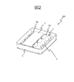
- FIG. 2 is a perspective view of the power conversion device 100 according to the present embodiment.
- the semiconductor module 1, the first cooler 2A, the second cooler 2B, the bus bar module 3, the capacitor 4, and the pressing member 5 are housed in the housing 6.
- the housing 6 is provided with a lid that covers the upper part of the housing 6, but the illustration is omitted.
- the power conversion device 100 mutually converts DC power and AC power by the switching operation of a plurality of semiconductor elements in the semiconductor module 1 and the operation of a capacitor 4 or the like that smoothes the voltage ripple accompanying the switching of the semiconductor elements.
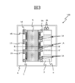
- FIG. 3 is a top view of the power conversion device 100 according to the present embodiment.
- the same parts as those in FIG. 1 are designated by the same reference numerals, and the description thereof will be omitted.
- the semiconductor module 1 has three, each of which has two DC terminals 1A and one AC terminal 1B.
- the two DC terminals 1A are connected to the negative electrode bus bar and the positive electrode bus bar in the bus bar module 3, respectively, and further connected to the capacitor 4 via the respective bus bars.
- the AC terminal 1B is connected to a motor provided outside the power conversion device 100.
- the power supply terminals 3A derived from the bus bars of the positive electrode and the negative electrode are connected to a DC power supply provided outside the power conversion device 100.
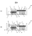
- FIG. 4A is a cross-sectional view of the power conversion device 100, which is a cross-sectional view taken along the line XX shown in FIG.
- FIG. 4B is a cross-sectional view of the power conversion device 100, which is a cross-sectional view taken along the line YY'shown in FIG.
- the DC terminal 1A of the semiconductor module 1 is connected to the bus bar 31 in the bus bar module 3.
- the insulating member 32 in the bus bar module 3 insulates the bus bars 31 having different potentials.
- the pressing member 5 is fixed to the convex portions 6A and 6B of the housing 6 by the bolts 5A and 5B.
- the pressing member 5 presses the second cooler 2B, the semiconductor module 1, and the first cooler 2A against the housing 6.
- the pressing member 5 sandwiches the bus bar module 3 with the convex portion 6A of the housing 6. That is, a part of the bus bar module 3 is sandwiched between a part of the housing 6 and the pressing member.
- An annular conductor 8 is arranged around the bolt 5A in the sandwiched bus bar module 3.
- bus bar module 3 has been described as an example in which a part of the bus bar module 3 is sandwiched between a part of the housing 6 and the pressing member 5, a part of the bus bar module 3 is formed between the part of the housing 6 and the pressing member 5. It suffices if they are in contact.
- the bus bar module 3 and the pressing member 5 are arranged side by side in the same plane, and the end surface 3E of the bus bar module 3 and the end surface 5E of the pressing member 5 are brought into contact with each other. Then, the bus bar module 3 and the pressing member 5 are fixed to the convex portion 6A of the housing 6 by the bolts 5A.
- the heat generated in the semiconductor module 1 is cooled by the first cooler 2A and the second cooler 2B. Further, the heat generated in the semiconductor module 1 is transferred to the bus bar module 3 via the DC terminal 1A of the semiconductor module 1. Then, as shown in FIG. 4B, the heat transferred to the bus bar module 3 is transferred to the pressing member 5 via the annular conductor 8 and the bolt 5A.
- the annular conductor 8 is a conductor built in the bus bar module 3 and receives the bolt 5A.
- the material of the annular conductor 8 is copper or aluminum.
- the heat transferred to the pressing member 5 is cooled by the second cooler 2B.
- the heat transferred to the convex portion 6A of the housing 6 is transferred to the first cooler 2A via the housing 6 and cooled.
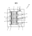
- FIG. 5 is a top view of the power conversion device 200 according to the present embodiment.
- the same parts as those of the power conversion device 100 according to the first embodiment shown in FIG. 3 are designated by the same reference numerals, and the description thereof will be omitted.
- the shape of the pressing member 5' is different from that of the first embodiment, and the pressing member 5'is formed so as to cover the DC terminal 1A.
- FIG. 6A is a cross-sectional view of the power conversion device 200, which is a cross-sectional view taken along the line XX shown in FIG.
- FIG. 6B is a cross-sectional view of the power conversion device 200, which is a cross-sectional view taken along the line YY'shown in FIG.
- the same parts as those of the power conversion device 100 according to the first embodiment shown in FIGS. 4 (A) and 4 (B) are designated by the same reference numerals, and the description thereof will be omitted.
- the pressing member 5' is formed so as to cover the DC terminal 1A, and the pressing member 5'contacts the DC terminal 1A and the bus bar module 3 via the insulating sheet 7. ing.
- the insulating sheet 7 is a heat-conducting sheet having an electrical insulating function.
- the pressing member 5' is fixed to the convex portions 6A and 6B of the housing 6 by the bolts 5A and 5B.
- An annular conductor 8 is arranged around the bolt 5A.
- the heat generated in the semiconductor module 1 is cooled by the first cooler 2A and the second cooler 2B. Further, the heat generated in the semiconductor module 1 is transferred to the bus bar module 3 and the insulating sheet 7 via the DC terminal 1A of the semiconductor module 1. The heat transferred to the insulating sheet 7 is transferred to the second cooler 2B via the pressing member 5'and is cooled here. Further, as shown in FIG. 5B, the heat transferred to the bus bar module 3 is transferred to the pressing member 5'via the annular conductor 8 and the bolt 5A, and is cooled by the second cooler 2B. On the other hand, the heat transferred to the convex portion 6A of the housing 6 is transferred to the first cooler 2A via the housing 6 and cooled.
- FIG. 7 is a cross-sectional view of the power conversion device 300 according to the present embodiment, which corresponds to the cross section taken along the line YY shown in FIG.
- the same parts as those of the power conversion device 100 according to the first embodiment shown in FIG. 4 are designated by the same reference numerals, and the description thereof will be omitted.
- a heat conductive material 9 is provided between the pressing member 5 and the second cooler 2B.
- the heat conductive material 9 is, for example, grease or a heat radiating sheet.
- the heat conductive material 9 reduces the contact thermal resistance between the pressing member 5 and the second cooler 2B. As a result, the heat transferred from the bus bar module 3 to the pressing member 5 is cooled more efficiently by the second cooler 2B. It should be noted that this embodiment can be applied not only to the first embodiment but also to the second embodiment.
- FIG. 8 is a cross-sectional view of the motor-integrated power converter 800.
- the motor-integrated power conversion device 800 integrally comprises the power conversion device 100 and the motor 20.
- the power conversion device 100 shown in FIG. 8 corresponds to a cross section taken along the line YY shown in FIG. 3, and is the same as the power conversion device 100 according to the first embodiment shown in FIG. The description thereof will be omitted by adding the reference numerals.
- the motor-integrated power conversion device 800 is integrally configured with the power conversion device 100, and is arranged on the opposite side of the pressing member 5 with the bus bar module 3, the first cooler 2A, and the second cooler 2B interposed therebetween. 20 and.
- the power conversion device 100 converts a DC power source into three-phase AC power to drive the motor 20.
- the motor 20 includes a rotor 21, a stator 22, a motor housing 23, an inlet pipe 24 for the refrigerant W, and an outlet pipe 25 for the refrigerant W.
- the stator 22 is cooled by the refrigerant W flowing in the motor housing 23, but the flow path in the motor housing 23 near the power conversion device 100 is interrupted in order to keep the height of the entire device low. Therefore, the heat generated by the stator 22 may be transmitted to the housing 6 of the power conversion device 100.
- the path for heat dissipation from the bus bar module 3 to the first cooler 2A on the motor 20 side overlaps with the heat transfer path M from the stator 22, making it difficult to dissipate heat.
- the bus bar module 3 can sufficiently dissipate heat. That is, even in the motor-integrated power converter 800, the bus bar module 3 can sufficiently dissipate heat, and the heat transferred to the capacitor 4 can be suppressed more efficiently.
- the power conversion device 100 shown in the first embodiment has been described as an example, but not only the first embodiment but also the power conversion devices 200 and the third in the second embodiment.
- the power conversion device 300 shown in the embodiment may be used.
- FIG. 9 is a cross-sectional view of the motor-integrated power converter 900.
- the motor-integrated power conversion device 900 is an integral configuration of the power conversion device 400 and the motor 20.
- the power conversion device 400 shown in FIG. 9 corresponds to a cross section taken along the line YY shown in FIG. 3, and is the same as the power conversion device 100 according to the first embodiment shown in FIG. The description thereof will be omitted by adding the reference numerals.
- the power conversion device 400 arranges the heat insulating member 12 between the capacitor 4 and the housing 6, and further, the convex portion 6A of the housing 6 to which the pressing member 5 is attached by the bolts 5A and 5B. 6B is composed of the heat insulating member 12.
- Other configurations are the same as those of the power converter 100.
- the same heat insulating member 12 as shown in the power conversion device 400 may be provided.
- the motor 20 has the same configuration as that shown in the fourth embodiment, and the same reference numerals are given to the same parts, and the description thereof will be omitted.
- the thermal resistance of the heat transfer path from the bus bar module 3 to the first cooler 2A is small, the heat received by the bus bar module 3 can be easily dissipated to the first cooler 2A, but it is also easily affected by the heat generated by the stator 22. Become. Therefore, in the present embodiment, the thermal resistance between the first cooler 2A and the bus bar module 3 is made larger than the thermal resistance between the second cooler 2B and the bus bar module 3. As a result, the heat received by the bus bar module 3 is mainly dissipated to the second cooler 2B, so that the temperature of the bus bar module 3 in the motor-integrated power converter 900 can be further reduced.
- the material of the heat insulating member 12 is resin or the like.
- the heat insulating member 12 between the pressing member 5 and the housing 6 of the power conversion device 400, specifically, the convex portion 6A of the housing 6 to which the pressing member 5 is attached by the bolts 5A and 5B, By configuring 6B with the heat insulating member 12, it is possible to suppress the transfer of heat from the stator 22 to the bus bar module 3 via the pressing member 5.
- the power converters 100, 200, 300, and 400 are pressed against the semiconductor module 1 containing the semiconductor element, the coolers 2A and 2B for cooling the semiconductor module 1, and the coolers 2A and 2B against the semiconductor module 1.
- the bus bar module 3 in which the members 5, 5', the bus bar 31 that electrically connects the semiconductor module 1 and the capacitor 4 are sealed by the insulating member 32, the semiconductor module 1, the coolers 2A, 2B, and the bus bar module 3 are attached.
- a housing 6 for storing is provided, and a part of the bus bar module 3 comes into contact with a part of the housing 6 and the pressing members 5, 5'. As a result, the heat transferred from the semiconductor module to the capacitor via the bus bar module can be suppressed.
- the present invention is not limited to the above-described embodiment, and other embodiments that can be considered within the scope of the technical idea of the present invention are also included within the scope of the present invention as long as the features of the present invention are not impaired. .. Further, the configuration may be a combination of the above-described embodiments.
Landscapes
- Engineering & Computer Science (AREA)
- Power Engineering (AREA)
- Microelectronics & Electronic Packaging (AREA)
- Physics & Mathematics (AREA)
- Thermal Sciences (AREA)
- Inverter Devices (AREA)
- Cooling Or The Like Of Semiconductors Or Solid State Devices (AREA)
Abstract
半導体モジュールからバスバーモジュールを介してコンデンサに伝わる熱は考慮されていない。 半導体モジュール1で発生した熱は、半導体モジュール1の直流端子1Aを介して、バスバーモジュール3へ伝わる。そして、バスバーモジュール3へ伝わった熱は、図4(B)に示すように、環状導体8、ボルト5Aを介して、押付部材5へ伝わる。押付部材5は、第2冷却器2Bと密着しているので、押付部材5へ伝わった熱は第2冷却器2Bで冷却される。一方、筐体6の凸部6Aに伝わった熱は、筐体6を介して第1冷却器2Aへ伝わって冷却される。これにより、コンデンサ4がバスバーモジュール3を介して半導体モジュール1に接続される構成において、半導体モジュール1からコンデンサ4に伝わる熱を抑制できる。
Description
本発明は、電力変換装置およびモータ一体型電力変換装置に関する。
インバータやコンバータ等の電力変換装置は、複数の半導体素子のスイッチング動作によって直流電力と交流電力の電力変換を行っている。このような電力変換装置では、直流電源から半導体モジュールへ供給される電流を平滑化するコンデンサが、バスバーモジュールを介して半導体モジュールに電気的に接続されている。電力変換装置の小型化により、半導体モジュールとコンデンサが近接し、半導体モジュールからバスバーを経由してコンデンサに熱が伝導する。
特許文献1には、半導体モジュールの半導体端子とコンデンサのコンデンサ端子とを互いに直接接触させるとともに、冷却器に対して熱的に接触させる電力変換装置が開示されている。
特許文献1に記載の装置は、半導体モジュールからバスバーモジュールを介してコンデンサに伝わる熱は考慮されていない。
本発明による電力変換装置は、半導体素子を内蔵する半導体モジュールと、前記半導体モジュールを冷却する冷却器と、前記冷却器を前記半導体モジュールに押し付ける押付部材と、前記半導体モジュールとコンデンサとを電気的に接続するバスバーを絶縁部材で封止したバスバーモジュールと、前記半導体モジュールと前記冷却器と前記バスバーモジュールとを収納する筐体と、を備え、前記バスバーモジュールの一部が前記筐体の一部と前記押付部材とに接触する。
本発明によれば、半導体モジュールからバスバーモジュールを介してコンデンサに伝わる熱を抑制できる。
以下、図面を参照して本発明の実施形態を説明する。以下の記載および図面は、本発明を説明するための例示であって、説明の明確化のため、適宜、省略および簡略化がなされている。本発明は、他の種々の形態でも実施する事が可能である。特に限定しない限り、各構成要素は単数でも複数でも構わない。
図面において示す各構成要素の位置、大きさ、形状、範囲などは、発明の理解を容易にするため、実際の位置、大きさ、形状、範囲などを表していない場合がある。このため、本発明は、必ずしも、図面に開示された位置、大きさ、形状、範囲などに限定されない。
[第1の実施形態] 図1から図4を参照して第1の実施形態に係わる電力変換装置100を説明する。
図1は、本実施形態に係わる電力変換装置100の分解斜視図である。図1に示すように、半導体モジュール1の一方の面に第1冷却器2Aが、他方の面に第2冷却器2Bが当接される。半導体モジュール1は、シリコン(Si、ケイ素)を母材とするIGBTや、SiC(炭化ケイ素)を母材とするMOSFET等の半導体素子を内蔵する。第1冷却器2Aおよび第2冷却器2Bは、その内部に冷却用流体(ロングライフクーラント等)を流す経路を形成し、アルミニウムや樹脂で構成される。半導体モジュール1の両面に配置された第1冷却器2Aおよび第2冷却器2Bによって、半導体素子のスイッチング動作により発熱した半導体モジュール1を冷却する。
図1は、本実施形態に係わる電力変換装置100の分解斜視図である。図1に示すように、半導体モジュール1の一方の面に第1冷却器2Aが、他方の面に第2冷却器2Bが当接される。半導体モジュール1は、シリコン(Si、ケイ素)を母材とするIGBTや、SiC(炭化ケイ素)を母材とするMOSFET等の半導体素子を内蔵する。第1冷却器2Aおよび第2冷却器2Bは、その内部に冷却用流体(ロングライフクーラント等)を流す経路を形成し、アルミニウムや樹脂で構成される。半導体モジュール1の両面に配置された第1冷却器2Aおよび第2冷却器2Bによって、半導体素子のスイッチング動作により発熱した半導体モジュール1を冷却する。
半導体モジュール1の端子はバスバーモジュール3内のバスバーと接続された端子と接続される。バスバーモジュール3は、バスバーを絶縁部材で封止したモジュールである。
バスバーは、電気配線のための板状導体であり、銅やアルミニウムが用いられる。本実施形態では、半導体モジュール1とコンデンサ4の電気的接続に用いられる。絶縁部材は、電位の異なるバスバー間を絶縁する樹脂等の部材である。
バスバーは、電気配線のための板状導体であり、銅やアルミニウムが用いられる。本実施形態では、半導体モジュール1とコンデンサ4の電気的接続に用いられる。絶縁部材は、電位の異なるバスバー間を絶縁する樹脂等の部材である。
コンデンサ4は、半導体モジュール1に隣接し、バスバーモジュール3の図示下方に設置される。コンデンサ4は、半導体素子のスイッチングに伴う電圧リプルを平滑化する部材であり、フィルムコンデンサや電解コンデンサが用いられる。
第2冷却器2Bの半導体モジュール1と当接する面の反対側の面(図示の上面)には、第2冷却器2Bを覆うように押付部材5が設けられる。押付部材5は、半導体モジュール1、第1冷却器2A、および第2冷却器2Bを筐体6に押し付けて固定するための部材であり、アルミニウムや鉄等で構成される。押付部材5は、押付部材5と一体的に形成された突出部をバスバーモジュール3側とその反対側に計8個形成している。押付部材5は、突出部において、ボルト5A、5Bにより筐体6の一部に固定される。
筐体6は、半導体モジュール1、第1冷却器2A、第2冷却器2B、バスバーモジュール3、コンデンサ4、押付部材5を収納する。筐体6の底部には、収納される各部品の位置合わせ、およびボルト5A、5Bの受け部として、凸部6A、6Bが設けられる。凸部6A、6Bは筐体6と一体的に設けてもよく、別体に設けてもよく、いずれの場合も筐体6の一部を成す。筐体6および凸部6A、6Bの材料は熱伝導率が高いアルミニウムである。
図2は、本実施形態に係わる電力変換装置100の斜視図である。
図2に示すように、筐体6には、半導体モジュール1、第1冷却器2A、第2冷却器2B、バスバーモジュール3、コンデンサ4、押付部材5が収納される。筐体6には筐体6の上部を覆う蓋が設けられるが、図示を省略している。
図2に示すように、筐体6には、半導体モジュール1、第1冷却器2A、第2冷却器2B、バスバーモジュール3、コンデンサ4、押付部材5が収納される。筐体6には筐体6の上部を覆う蓋が設けられるが、図示を省略している。
電力変換装置100は、半導体モジュール1内の複数の半導体素子のスイッチング動作、半導体素子のスイッチングに伴う電圧リプルを平滑化するコンデンサ4等の動作によって直流電力と交流電力とを相互に電力変換する。
図3は、本実施形態に係わる電力変換装置100の上面図である。図1と同一の個所には同一の符号を付してその説明を省略する。
半導体モジュール1は、本実施形態においては、3個有し、各々は、2個の直流端子1A、1個の交流端子1Bを有する。2個の直流端子1Aは、バスバーモジュール3内の負極のバスバーと正極のバスバーへそれぞれ接続され、さらに、それぞれのバスバーを介してコンデンサ4へ接続される。交流端子1Bは、電力変換装置100の外部に設けられたモータと接続される。正極および負極のバスバーから導出された電源端子3Aは、電力変換装置100の外部に設けられた直流電源と接続される。
図4(A)は、電力変換装置100の断面図であり、図3に示すX-X’線における断面である。図4(B)は、電力変換装置100の断面図であり、図3に示すY-Y’線における断面である。
図4(A)に示すように、半導体モジュール1の直流端子1Aは、バスバーモジュール3内のバスバー31と接続されている。バスバーモジュール3内の絶縁部材32は、電位の異なるバスバー31を絶縁する。
図4(B)に示すように、押付部材5は、ボルト5A、5Bによって筐体6の凸部6A、6Bに固定される。これにより、押付部材5は、第2冷却器2B、半導体モジュール1、第1冷却器2Aを筐体6へ押し付ける。さらに、押付部材5は、筐体6の凸部6Aとの間にバスバーモジュール3を挟み込む。すなわち、バスバーモジュール3の一部が筐体6の一部と押付部材との間に挟まれる。挟み込まれたバスバーモジュール3内であって、ボルト5Aの周囲には環状導体8が配置される。なお、バスバーモジュール3の一部が筐体6の一部と押付部材5との間に挟まれる例で説明したが、バスバーモジュール3の一部が筐体6の一部と押付部材5とに接触していればよい。例えば、バスバーモジュール3と押付部材5を同一平面内に並設し、バスバーモジュール3の端面3Eと押付部材5の端面5Eを接触させる。そして、バスバーモジュール3と押付部材5をボルト5Aによって筐体6の凸部6Aに固定する。
半導体モジュール1で発生した熱は、図4(A)に示すように、第1冷却器2Aおよび第2冷却器2Bで冷却される。さらに、半導体モジュール1で発生した熱は、半導体モジュール1の直流端子1Aを介して、バスバーモジュール3へ伝わる。そして、バスバーモジュール3へ伝わった熱は、図4(B)に示すように、環状導体8、ボルト5Aを介して、押付部材5へ伝わる。なお、環状導体8は、バスバーモジュール3に内蔵され、ボルト5Aを受ける導体である。環状導体8の材料は銅またはアルミニウムである。環状導体8を設けることで、ボルト締結部の熱抵抗を低減できるので、さらに放熱性を向上できる。
押付部材5は、第2冷却器2Bと密着しているので、押付部材5へ伝わった熱は第2冷却器2Bで冷却される。一方、筐体6の凸部6Aに伝わった熱は、筐体6を介して第1冷却器2Aへ伝わって冷却される。
押付部材5は、第2冷却器2Bと密着しているので、押付部材5へ伝わった熱は第2冷却器2Bで冷却される。一方、筐体6の凸部6Aに伝わった熱は、筐体6を介して第1冷却器2Aへ伝わって冷却される。
これにより、コンデンサ4がバスバーモジュール3を介して半導体モジュール1に接続される構成において、半導体モジュール1からバスバーモジュール3を介してコンデンサ4に伝わる熱を抑制できる。
[第2の実施形態] 図5、図6を参照して第2の実施形態に係わる電力変換装置200を説明する。
図5は、本実施形態に係わる電力変換装置200の上面図である。図3に示した第1の実施形態に係わる電力変換装置100と同一の個所には同一の符号を付してその説明を省略する。
図5は、本実施形態に係わる電力変換装置200の上面図である。図3に示した第1の実施形態に係わる電力変換装置100と同一の個所には同一の符号を付してその説明を省略する。
本実施形態では、図5に示すように、押付部材5’の形状が第1の実施形態とは相違しており、押付部材5’が直流端子1Aに覆いかぶさる形状に形成されている。
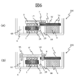
図6(A)は、電力変換装置200の断面図であり、図5に示すX-X’線における断面である。図6(B)は、電力変換装置200の断面図であり、図5に示すY-Y’線における断面である。図4(A)、図4(B)に示した第1の実施形態に係わる電力変換装置100と同一の個所には同一の符号を付してその説明を省略する。
図6(A)に示すように、押付部材5’が直流端子1Aに覆いかぶさる形状に形成され、押付部材5’は、絶縁シート7を介して、直流端子1A、さらにバスバーモジュール3と接触している。絶縁シート7は電気的な絶縁機能を有する伝熱性のシートである。
図6(B)に示すように、押付部材5’は、ボルト5A、5Bによって筐体6の凸部6A、6Bに固定される。ボルト5Aの周囲には環状導体8が配置される。
半導体モジュール1で発生した熱は、図6(A)に示すように、第1冷却器2Aおよび第2冷却器2Bで冷却される。さらに、半導体モジュール1で発生した熱は、半導体モジュール1の直流端子1Aを介して、バスバーモジュール3および絶縁シート7へ伝わる。
絶縁シート7へ伝わった熱は、押付部材5’を介して第2冷却器2Bへ伝わり、ここで冷却される。また、バスバーモジュール3へ伝わった熱は、図5(B)に示すように、環状導体8、ボルト5Aを介して、押付部材5’へ伝わり、第2冷却器2Bで冷却される。一方、筐体6の凸部6Aに伝わった熱は、筐体6を介して第1冷却器2Aへ伝わって冷却される。
絶縁シート7へ伝わった熱は、押付部材5’を介して第2冷却器2Bへ伝わり、ここで冷却される。また、バスバーモジュール3へ伝わった熱は、図5(B)に示すように、環状導体8、ボルト5Aを介して、押付部材5’へ伝わり、第2冷却器2Bで冷却される。一方、筐体6の凸部6Aに伝わった熱は、筐体6を介して第1冷却器2Aへ伝わって冷却される。
これにより、コンデンサ4がバスバーモジュール3を介して半導体モジュール1に接続される構成において、半導体モジュール1からバスバーモジュール3を介してコンデンサ4に伝わる熱をより効率よく抑制できる。
[第3の実施形態] 図7を参照して第3の実施形態に係わる電力変換装置300を説明する。
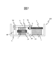
図7は、本実施形態に係わる電力変換装置300の断面図であり、図3に示すY-Y’線における断面に相当する。図4に示した第1の実施形態に係わる電力変換装置100と同一の個所には同一の符号を付してその説明を省略する。
図7は、本実施形態に係わる電力変換装置300の断面図であり、図3に示すY-Y’線における断面に相当する。図4に示した第1の実施形態に係わる電力変換装置100と同一の個所には同一の符号を付してその説明を省略する。
本実施形態では、図7に示すように、押付部材5と第2冷却器2Bとの間に熱伝導材9を設けた。熱伝導材9は、例えば、グリースや放熱シートである。熱伝導材9は、押付部材5と第2冷却器2Bとの間の接触熱抵抗を低減する。これにより、バスバーモジュール3から押付部材5へ伝わった熱が第2冷却器2Bでより効率的に冷却される。なお、本実施形態は、第1の実施形態のみならず、第2の実施形態にも適用することができる。
[第4の実施形態] 図8を参照して第4の実施形態に係わるモータ一体型電力変換装置800を説明する。
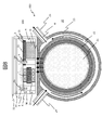
図8は、モータ一体型電力変換装置800の断面図である。図8に示すように、モータ一体型電力変換装置800は、電力変換装置100とモータ20を一体的に構成したものである。なお、図8に示す電力変換装置100は、図3に示すY-Y’線における断面に相当し、図4に示した第1の実施形態に係わる電力変換装置100と同一の個所には同一の符号を付してその説明を省略する。
図8は、モータ一体型電力変換装置800の断面図である。図8に示すように、モータ一体型電力変換装置800は、電力変換装置100とモータ20を一体的に構成したものである。なお、図8に示す電力変換装置100は、図3に示すY-Y’線における断面に相当し、図4に示した第1の実施形態に係わる電力変換装置100と同一の個所には同一の符号を付してその説明を省略する。
モータ一体型電力変換装置800は、電力変換装置100と一体的に構成され、押付部材5の反対側に、バスバーモジュール3及び第1冷却器2Aおよび第2冷却器2Bを挟んで配置されるモータ20とを備える。電力変換装置100は、直流電源を三相交流電力に変換してモータ20を駆動する。
モータ20は、回転子21、固定子22、モータ筐体23、冷媒Wの入り口パイプ24、冷媒Wの出口パイプ25を備える。
モータ20を駆動するために固定子22に電流が流れることで、固定子22が発熱する。固定子22はモータ筐体23内を流れる冷媒Wで冷却されるが、装置全体の高さを低く抑えるために、電力変換装置100付近のモータ筐体23内の流路が途絶している。そのため、固定子22の発熱が電力変換装置100の筐体6に伝わる虞がある。この場合、バスバーモジュール3からモータ20側の第1冷却器2Aへ放熱する経路が固定子22からの伝熱経路Mと重なり、放熱しづらくなるが、本実施形態では、モータ20から見て半導体モジュール1の反対側の第2冷却器2Bにもバスバーモジュール3からの放熱経路が確保されるため、バスバーモジュール3を十分に放熱できる。すなわち、モータ一体型電力変換装置800であっても、バスバーモジュール3を十分放熱することが可能であり、コンデンサ4に伝わる熱をより効率よく抑制できる。
なお、本実施形態では第1の実施形態で示した電力変換装置100を例に説明したが、第1の実施形態のみならず、第2の実施形態で示した電力変換装置200、第3の実施形態で示した電力変換装置300を用いてもよい。
[第5の実施形態] 図9を参照して第5の実施形態に係わるモータ一体型電力変換装置900を説明する。
図9は、モータ一体型電力変換装置900の断面図である。図9に示すように、モータ一体型電力変換装置900は、電力変換装置400とモータ20を一体的に構成したものである。なお、図9に示す電力変換装置400は、図3に示すY-Y’線における断面に相当し、図4に示した第1の実施形態に係わる電力変換装置100と同一の個所には同一の符号を付してその説明を省略する。
図9は、モータ一体型電力変換装置900の断面図である。図9に示すように、モータ一体型電力変換装置900は、電力変換装置400とモータ20を一体的に構成したものである。なお、図9に示す電力変換装置400は、図3に示すY-Y’線における断面に相当し、図4に示した第1の実施形態に係わる電力変換装置100と同一の個所には同一の符号を付してその説明を省略する。
電力変換装置400は、図9に示すように、コンデンサ4と筐体6の間に断熱部材12を配置し、さらに、ボルト5A、5Bによって押付部材5が取り付けられる筐体6の凸部6A、6Bを断熱部材12によって構成する。その他の構成は電力変換装置100と同様である。なお、第2の実施形態で示した電力変換装置200、第3の実施形態で示した電力変換装置300において、電力変換装置400に示したと同様の断熱部材12を設けてもよい。
モータ20は、第4の実施形態で示した構成と同様であり、同一箇所には同一の符号を付してその説明を省略する。
バスバーモジュール3から第1冷却器2Aまでの伝熱経路の熱抵抗が小さいと、バスバーモジュール3が受ける熱を第1冷却器2Aに放熱しやすくなる反面、固定子22の発熱の影響も受けやすくなる。そこで、本実施形態では、第1冷却器2Aとバスバーモジュール3との間の熱抵抗が、第2冷却器2Bとバスバーモジュール3との間の熱抵抗よりも大きくした。これにより、バスバーモジュール3が受ける熱は主に第2冷却器2Bに放熱するようにすることで、モータ一体型電力変換装置900におけるバスバーモジュール3のさらなる温度低減が可能となる。
固定子22からバスバーモジュール3の伝熱経路に断熱部材12を配置することで、当該経路の熱抵抗を増加させる。断熱部材12の材料は、樹脂等である。
さらに、押付部材5と電力変換装置400の筐体6との間に断熱部材12を設けることで、具体的には、ボルト5A、5Bによって押付部材5が取り付けられる筐体6の凸部6A、6Bを断熱部材12によって構成することで、押付部材5を経由してバスバーモジュール3に固定子22からの熱が伝わることを抑制できる。
さらに、モータ20とコンデンサ4の間に断熱部材12を設けることで、固定子22からのコンデンサ4への熱伝導を抑制できる。
以上説明した実施形態によれば、次の作用効果が得られる。
(1)電力変換装置100、200、300、400は、半導体素子を内蔵する半導体モジュール1と、半導体モジュール1を冷却する冷却器2A、2Bと、冷却器2A、2Bを半導体モジュール1に押し付ける押付部材5、5’と、半導体モジュール1とコンデンサ4とを電気的に接続するバスバー31を絶縁部材32で封止したバスバーモジュール3と、半導体モジュール1と冷却器2A、2Bとバスバーモジュール3とを収納する筐体6と、を備え、バスバーモジュール3の一部が筐体6の一部と押付部材5、5’とに接触する。これにより、半導体モジュールからバスバーモジュールを介してコンデンサに伝わる熱を抑制できる。
(1)電力変換装置100、200、300、400は、半導体素子を内蔵する半導体モジュール1と、半導体モジュール1を冷却する冷却器2A、2Bと、冷却器2A、2Bを半導体モジュール1に押し付ける押付部材5、5’と、半導体モジュール1とコンデンサ4とを電気的に接続するバスバー31を絶縁部材32で封止したバスバーモジュール3と、半導体モジュール1と冷却器2A、2Bとバスバーモジュール3とを収納する筐体6と、を備え、バスバーモジュール3の一部が筐体6の一部と押付部材5、5’とに接触する。これにより、半導体モジュールからバスバーモジュールを介してコンデンサに伝わる熱を抑制できる。
本発明は、上記の実施形態に限定されるものではなく、本発明の特徴を損なわない限り、本発明の技術思想の範囲内で考えられるその他の形態についても、本発明の範囲内に含まれる。また、上述の実施形態を組み合わせた構成としてもよい。
1・・・半導体モジュール、1A・・・直流端子、1B・・・交流端子、2A・・・第1冷却器、2B・・・第2冷却器、3・・・バスバーモジュール、3A・・・電源端子、4・・・コンデンサ、5、5’・・・押付部材、5A、5B・・・ボルト、6・・・筐体、6A、6B・・・凸部、7・・・絶縁シート、8・・・環状導体、9・・・熱伝導材、20・・・モータ、21・・・回転子、22・・・固定子、23・・・モータ筐体、24・・・入り口パイプ、25・・・出口パイプ、31・・・バスバー、32・・・絶縁部材、100、200、300、400・・・電力変換装置。
Claims (8)
- 半導体素子を内蔵する半導体モジュールと、
前記半導体モジュールを冷却する冷却器と、
前記冷却器を前記半導体モジュールに押し付ける押付部材と、
前記半導体モジュールとコンデンサとを電気的に接続するバスバーを絶縁部材で封止したバスバーモジュールと、
前記半導体モジュールと前記冷却器と前記バスバーモジュールとを収納する筐体と、を備え、
前記バスバーモジュールの一部が前記筐体の一部と前記押付部材とに接触する電力変換装置。 - 請求項1に記載の電力変換装置において、
前記バスバーモジュールの一部が前記筐体の一部と前記押付部材との間に挟まれる電力変換装置。 - 請求項1または請求項2に記載の電力変換装置において、
前記押付部材は絶縁シートを介して前記半導体モジュールの主端子に接触する電力変換装置。 - 請求項1または請求項2に記載の電力変換装置において、
前記冷却器は、前記半導体モジュールと前記筐体との間に配置される第1冷却器と、前記押付部材と前記半導体モジュールとの間に配置される第2冷却器と、により構成される電力変換装置。 - 請求項4に記載の電力変換装置において、
前記第2冷却器と前記押付部材との間に熱伝導材を設けた電力変換装置。 - 請求項1または請求項2に記載の電力変換装置と、
前記電力変換装置と一体的に構成され、前記押付部材の反対側に、前記バスバーモジュール及び前記冷却器を挟んで配置されるモータとを備えたモータ一体型電力変換装置。 - 請求項6に記載のモータ一体型電力変換装置であって、
前記冷却器は、前記半導体モジュールと前記モータとの間に配置される第1冷却器と、前記押付部材と前記半導体モジュールとの間に配置される第2冷却器と、により構成されるモータ一体型電力変換装置。 - 請求項7に記載のモータ一体型電力変換装置であって、
前記第1冷却器と前記バスバーモジュールとの間の熱抵抗が、前記第2冷却器と前記バスバーモジュールとの間の熱抵抗よりも大きいモータ一体型電力変換装置。
Priority Applications (3)
| Application Number | Priority Date | Filing Date | Title |
|---|---|---|---|
| CN202080055942.3A CN114208014B (zh) | 2019-09-20 | 2020-07-31 | 功率转换装置和电动机一体型功率转换装置 |
| DE112020003530.1T DE112020003530T5 (de) | 2019-09-20 | 2020-07-31 | Leistungsumsetzungsvorrichtung und in einen motor integrierte leistungsumsetzungsvorrichtung |
| US17/760,729 US11956933B2 (en) | 2019-09-20 | 2020-07-31 | Power conversion device and motor-integrated power conversion device |
Applications Claiming Priority (2)
| Application Number | Priority Date | Filing Date | Title |
|---|---|---|---|
| JP2019-172014 | 2019-09-20 | ||
| JP2019172014A JP7208124B2 (ja) | 2019-09-20 | 2019-09-20 | 電力変換装置およびモータ一体型電力変換装置 |
Publications (1)
| Publication Number | Publication Date |
|---|---|
| WO2021053975A1 true WO2021053975A1 (ja) | 2021-03-25 |
Family
ID=74884198
Family Applications (1)
| Application Number | Title | Priority Date | Filing Date |
|---|---|---|---|
| PCT/JP2020/029397 Ceased WO2021053975A1 (ja) | 2019-09-20 | 2020-07-31 | 電力変換装置およびモータ一体型電力変換装置 |
Country Status (5)
| Country | Link |
|---|---|
| US (1) | US11956933B2 (ja) |
| JP (1) | JP7208124B2 (ja) |
| CN (1) | CN114208014B (ja) |
| DE (1) | DE112020003530T5 (ja) |
| WO (1) | WO2021053975A1 (ja) |
Families Citing this family (8)
| Publication number | Priority date | Publication date | Assignee | Title |
|---|---|---|---|---|
| JP7405671B2 (ja) * | 2020-03-30 | 2023-12-26 | 日立Astemo株式会社 | 電力変換装置 |
| JP6921282B1 (ja) * | 2020-07-17 | 2021-08-18 | 三菱電機株式会社 | 電力変換装置 |
| JP7191157B1 (ja) | 2021-06-07 | 2022-12-16 | 三菱電機株式会社 | スイッチング装置 |
| JP7580349B2 (ja) * | 2021-07-01 | 2024-11-11 | 日立Astemo株式会社 | パワー半導体装置 |
| JP7370408B2 (ja) * | 2022-03-24 | 2023-10-27 | 三菱電機株式会社 | 電力変換装置 |
| DE102022132755A1 (de) | 2022-12-09 | 2024-06-20 | Valeo Eautomotive Germany Gmbh | Invertermodul für ein elektrisch angetriebenes Fahrzeug |
| JP7902119B2 (ja) * | 2023-01-17 | 2026-08-07 | Astemo株式会社 | パワー半導体装置 |
| WO2026100063A1 (ja) * | 2024-11-11 | 2026-05-15 | 三菱電機モビリティ株式会社 | 電力変換装置 |
Citations (3)
| Publication number | Priority date | Publication date | Assignee | Title |
|---|---|---|---|---|
| JP2010166700A (ja) * | 2009-01-15 | 2010-07-29 | Denso Corp | 電子機器 |
| JP2015128138A (ja) * | 2013-11-27 | 2015-07-09 | 株式会社豊田自動織機 | 半導体装置 |
| JP2015201957A (ja) * | 2014-04-08 | 2015-11-12 | 株式会社ジェイテクト | モータ制御装置 |
Family Cites Families (8)
| Publication number | Priority date | Publication date | Assignee | Title |
|---|---|---|---|---|
| JP5326760B2 (ja) | 2009-04-14 | 2013-10-30 | 株式会社デンソー | 電力変換装置 |
| JP5492599B2 (ja) * | 2010-02-26 | 2014-05-14 | 日立オートモティブシステムズ株式会社 | 回転電機システム |
| US9263356B2 (en) * | 2012-05-28 | 2016-02-16 | Mitsubishi Electric Corporation | Semiconductor device |
| JP5714077B2 (ja) * | 2013-10-25 | 2015-05-07 | 三菱電機株式会社 | 接続導体の冷却装置及びそれを用いた電力変換装置 |
| JP6394262B2 (ja) * | 2014-10-14 | 2018-09-26 | 株式会社デンソー | 電力変換装置 |
| CA2986743C (en) * | 2015-05-26 | 2018-12-11 | Nissan Motor Co., Ltd. | Mechanically-electrically integrated electrical rotating apparatus |
| JP7432322B2 (ja) * | 2019-08-27 | 2024-02-16 | 株式会社Subaru | モータ装置 |
| JP7405671B2 (ja) * | 2020-03-30 | 2023-12-26 | 日立Astemo株式会社 | 電力変換装置 |
-
2019
- 2019-09-20 JP JP2019172014A patent/JP7208124B2/ja active Active
-
2020
- 2020-07-31 US US17/760,729 patent/US11956933B2/en active Active
- 2020-07-31 DE DE112020003530.1T patent/DE112020003530T5/de active Pending
- 2020-07-31 CN CN202080055942.3A patent/CN114208014B/zh active Active
- 2020-07-31 WO PCT/JP2020/029397 patent/WO2021053975A1/ja not_active Ceased
Patent Citations (3)
| Publication number | Priority date | Publication date | Assignee | Title |
|---|---|---|---|---|
| JP2010166700A (ja) * | 2009-01-15 | 2010-07-29 | Denso Corp | 電子機器 |
| JP2015128138A (ja) * | 2013-11-27 | 2015-07-09 | 株式会社豊田自動織機 | 半導体装置 |
| JP2015201957A (ja) * | 2014-04-08 | 2015-11-12 | 株式会社ジェイテクト | モータ制御装置 |
Also Published As
| Publication number | Publication date |
|---|---|
| US20220338370A1 (en) | 2022-10-20 |
| US11956933B2 (en) | 2024-04-09 |
| JP2021052443A (ja) | 2021-04-01 |
| CN114208014B (zh) | 2025-04-29 |
| CN114208014A (zh) | 2022-03-18 |
| JP7208124B2 (ja) | 2023-01-18 |
| DE112020003530T5 (de) | 2022-04-14 |
Similar Documents
| Publication | Publication Date | Title |
|---|---|---|
| JP7208124B2 (ja) | 電力変換装置およびモータ一体型電力変換装置 | |
| JP6349275B2 (ja) | 電力変換装置 | |
| JP6371001B2 (ja) | 電力変換装置 | |
| JP6932225B1 (ja) | 電力変換装置 | |
| KR102786035B1 (ko) | 차량, 및 차량용 전력 변환 장치 | |
| JP6409968B2 (ja) | 機電一体型の回転電機装置 | |
| CN107408554B (zh) | 电力转换装置 | |
| JP6867432B2 (ja) | 電力変換装置 | |
| CN113329587B (zh) | 电力转换装置 | |
| JP5664472B2 (ja) | 電力変換装置 | |
| JP7366082B2 (ja) | 電力変換装置 | |
| CN116742918A (zh) | 功率转换装置 | |
| JP6158051B2 (ja) | 電力変換装置 | |
| WO2013111234A1 (ja) | 電力変換装置 | |
| CN114446643B (zh) | 功率转换装置 | |
| CN103946977A (zh) | 功率转换装置 | |
| JP4038455B2 (ja) | 半導体装置 | |
| JP2012005191A (ja) | 電力変換装置 | |
| JP7504294B2 (ja) | 電子機器 | |
| WO2022215356A1 (ja) | 電気導体の冷却装置、電力変換装置及び回転電気機械 | |
| JP5434862B2 (ja) | 電力変換装置 | |
| JP7577021B2 (ja) | パワーモジュール | |
| JP2015089300A (ja) | 電源装置 | |
| WO2015140944A1 (ja) | パワーモジュール | |
| JP2007060733A (ja) | パワーモジュール |
Legal Events
| Date | Code | Title | Description |
|---|---|---|---|
| 121 | Ep: the epo has been informed by wipo that ep was designated in this application |
Ref document number: 20866597 Country of ref document: EP Kind code of ref document: A1 |
|
| 122 | Ep: pct application non-entry in european phase |
Ref document number: 20866597 Country of ref document: EP Kind code of ref document: A1 |
|
| WWG | Wipo information: grant in national office |
Ref document number: 202080055942.3 Country of ref document: CN |