WO2021049512A1 - 測定装置 - Google Patents
測定装置 Download PDFInfo
- Publication number
- WO2021049512A1 WO2021049512A1 PCT/JP2020/034067 JP2020034067W WO2021049512A1 WO 2021049512 A1 WO2021049512 A1 WO 2021049512A1 JP 2020034067 W JP2020034067 W JP 2020034067W WO 2021049512 A1 WO2021049512 A1 WO 2021049512A1
- Authority
- WO
- WIPO (PCT)
- Prior art keywords
- hole
- convex portion
- flow path
- hydraulic oil
- measuring device
- Prior art date
- Legal status (The legal status is an assumption and is not a legal conclusion. Google has not performed a legal analysis and makes no representation as to the accuracy of the status listed.)
- Ceased
Links
Images




Classifications
-
- G—PHYSICS
- G01—MEASURING; TESTING
- G01N—INVESTIGATING OR ANALYSING MATERIALS BY DETERMINING THEIR CHEMICAL OR PHYSICAL PROPERTIES
- G01N15/00—Investigating characteristics of particles; Investigating permeability, pore-volume or surface-area of porous materials
- G01N15/02—Investigating particle size or size distribution
- G01N15/0205—Investigating particle size or size distribution by optical means
-
- G—PHYSICS
- G01—MEASURING; TESTING
- G01N—INVESTIGATING OR ANALYSING MATERIALS BY DETERMINING THEIR CHEMICAL OR PHYSICAL PROPERTIES
- G01N15/00—Investigating characteristics of particles; Investigating permeability, pore-volume or surface-area of porous materials
- G01N15/02—Investigating particle size or size distribution
-
- G—PHYSICS
- G01—MEASURING; TESTING
- G01N—INVESTIGATING OR ANALYSING MATERIALS BY DETERMINING THEIR CHEMICAL OR PHYSICAL PROPERTIES
- G01N21/00—Investigating or analysing materials by the use of optical means, i.e. using sub-millimetre waves, infrared, visible or ultraviolet light
- G01N21/01—Arrangements or apparatus for facilitating the optical investigation
- G01N21/03—Cuvette constructions
- G01N21/05—Flow-through cuvettes
-
- G—PHYSICS
- G01—MEASURING; TESTING
- G01N—INVESTIGATING OR ANALYSING MATERIALS BY DETERMINING THEIR CHEMICAL OR PHYSICAL PROPERTIES
- G01N21/00—Investigating or analysing materials by the use of optical means, i.e. using sub-millimetre waves, infrared, visible or ultraviolet light
- G01N21/17—Systems in which incident light is modified in accordance with the properties of the material investigated
- G01N21/25—Colour; Spectral properties, i.e. comparison of effect of material on the light at two or more different wavelengths or wavelength bands
-
- G—PHYSICS
- G01—MEASURING; TESTING
- G01N—INVESTIGATING OR ANALYSING MATERIALS BY DETERMINING THEIR CHEMICAL OR PHYSICAL PROPERTIES
- G01N21/00—Investigating or analysing materials by the use of optical means, i.e. using sub-millimetre waves, infrared, visible or ultraviolet light
- G01N21/17—Systems in which incident light is modified in accordance with the properties of the material investigated
- G01N21/25—Colour; Spectral properties, i.e. comparison of effect of material on the light at two or more different wavelengths or wavelength bands
- G01N21/27—Colour; Spectral properties, i.e. comparison of effect of material on the light at two or more different wavelengths or wavelength bands using photo-electric detection ; circuits for computing concentration
-
- G—PHYSICS
- G01—MEASURING; TESTING
- G01N—INVESTIGATING OR ANALYSING MATERIALS BY DETERMINING THEIR CHEMICAL OR PHYSICAL PROPERTIES
- G01N21/00—Investigating or analysing materials by the use of optical means, i.e. using sub-millimetre waves, infrared, visible or ultraviolet light
- G01N21/17—Systems in which incident light is modified in accordance with the properties of the material investigated
- G01N21/59—Transmissivity
-
- G—PHYSICS
- G01—MEASURING; TESTING
- G01N—INVESTIGATING OR ANALYSING MATERIALS BY DETERMINING THEIR CHEMICAL OR PHYSICAL PROPERTIES
- G01N21/00—Investigating or analysing materials by the use of optical means, i.e. using sub-millimetre waves, infrared, visible or ultraviolet light
- G01N21/84—Systems specially adapted for particular applications
- G01N21/85—Investigating moving fluids or granular solids
-
- G—PHYSICS
- G01—MEASURING; TESTING
- G01N—INVESTIGATING OR ANALYSING MATERIALS BY DETERMINING THEIR CHEMICAL OR PHYSICAL PROPERTIES
- G01N33/00—Investigating or analysing materials by specific methods not covered by groups G01N1/00 - G01N31/00
- G01N33/26—Oils; Viscous liquids; Paints; Inks
- G01N33/28—Oils, i.e. hydrocarbon liquids
Definitions
- the present invention relates to a measuring device.
- Patent Document 1 discloses a photometric device provided with a photometric unit for observing fine particles and color tones (that is, contamination or deterioration of the hydraulic oil) in the circulation path of the hydraulic oil used as a power transmission medium for a hydraulic device. There is.
- Patent Document 1 it is necessary to secure a space for providing a photometric unit (sensor) and a branch flow path in advance in the flood control device, and the position where the sensor and the branch flow path are provided is limited. In addition, it is not easy to attach / detach the sensor or the branch flow path, and the maintainability is poor.
- the present invention has been made in view of such circumstances, and provides a measuring device capable of providing a measuring device for measuring the degree of contamination of a liquid such as hydraulic oil at an arbitrary position and having high maintainability.
- a measuring device capable of providing a measuring device for measuring the degree of contamination of a liquid such as hydraulic oil at an arbitrary position and having high maintainability. The purpose.
- the measuring device has, for example, a first through hole through which a liquid flows, a convex portion provided so as to project into the first through hole, and the convex portion.
- a first through hole and a second through hole are provided inside the housing, and the measuring unit measures the liquid flowing inside the second through hole.
- a convex portion is provided so as to project inside the first through hole (main flow path) which is a through hole penetrating the housing, and the second through hole (bypass flow path) penetrating the convex portion is provided.
- the inner diameter is smaller than the inner diameter of the first through hole.
- the convex portion has a substantially annular shape, and the length of the convex portion and the length of the second through hole may be substantially the same.
- the measuring device can be made into a simple shape and the housing can be miniaturized.
- the convex portion is adjacent to the first convex portion having a substantially annular shape and the first convex portion, and the shape when viewed along the flow direction of the liquid in the first through hole is a substantially partial annular shape.
- the second through hole penetrates the first convex portion and the second convex portion, and in the flow direction, the upstream end of the second convex portion is: It may be located on the upstream side of the upstream end of the first convex portion.
- the end face on the upstream side of the convex portion may have a gradient such that the opening area of the hollow portion of the convex portion gradually decreases toward the downstream.
- At least one of a first valve provided in the convex portion so as to cover the hollow portion of the convex portion and a second valve provided in the convex portion so as to cover the second through hole may be provided. Thereby, the amount of the liquid flowing through the first through hole and the second through hole can be adjusted.
- a third convex portion may be provided on the inner peripheral surface of the convex portion. This makes it easier for the liquid to flow into the second through hole.
- a measuring device for measuring the degree of contamination of a liquid such as hydraulic oil can be provided at an arbitrary position, and maintainability can be improved.
- the measuring device of the present invention is installed, for example, in a hydraulic device of a construction machine (not shown), and is provided in a hydraulic circuit of hydraulic oil supplied to the hydraulic device.
- the hydraulic system includes a filter, a pipe, a tank, a valve (not shown), and the like, and a measuring device is attached to the pipe.
- the hydraulic oil will be described as an example as the liquid to be measured for the degree of contamination, but the liquid to be measured is not limited to the hydraulic oil.
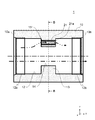
- FIG. 1 is a front view showing an outline of the measuring device 1.
- FIG. 2 is a cross-sectional view taken along the line AA of FIG.
- the measuring device 1 has a housing 10 attached to a pipe (not shown).
- the housing 10 has a substantially rectangular shape, and a substantially box-shaped insertion portion 11 in which a circuit board (not shown) or the like is provided inside is provided on the upper side (+ z side).
- the insertion portion 11 is provided with a connection portion 30 that supplies electric power or the like to a circuit board or the like (not shown). Note that the insertion portion 11 is not shown in FIG.
- a flow path hole 12 which is a linear through hole penetrating the housing 10 is provided inside the housing 10.
- the hydraulic oil flows inside the flow path hole 12 from the front to the back (in the + y direction). That is, the flow direction of the hydraulic oil is the y direction, the ⁇ y direction is the upstream side, and the + y direction is the downstream side. Both ends of the flow path hole 12 are opened to the upstream side surface 10a and the downstream side surface 10b of the housing 10.
- the housing 10 has a substantially ring-shaped convex portion 13 provided so as to project inside the flow path hole 12.
- the convex portion 13 is a diaphragm for narrowing the inner diameter of the flow path hole 12, and the convex portion 13 forms a small diameter portion 14 in the flow path hole 12.
- the hollow portion of the convex portion 13 is the main flow path.
- a linear through hole 15 that penetrates the convex portion 13 along the y direction is provided inside the convex portion 13.
- the through hole 15 and the flow path hole 12 are substantially parallel to each other.
- a transparent glass tube 21 is provided inside the through hole 15.
- the glass tube 21 is inserted inside the through hole 15, but the tube inserted inside the through hole 15 may be transparent and is not limited to the glass tube.
- a transparent resin tube may be inserted inside the through hole 15.
- the glass tube 21 is a linear hollow round bar.
- the hollow portion 21a of the glass tube 21 is a linear through hole penetrating the convex portion 13, is substantially parallel to the flow path hole 12, and has an inner diameter smaller than the diameter of the flow path hole 12 and the small diameter portion 14.
- the inside of the hollow portion 21a is a bypass flow path through which a part of the hydraulic oil flowing inside the flow path hole 12 flows, and when the hydraulic system is operated, about 1 to 5 liters of hydraulic oil flows inside the hollow portion 21a per minute. ..
- the flow direction of the hydraulic oil in the hollow portion 21a is substantially the same as the flow direction (y direction) of the hydraulic oil in the flow path hole 12.
- the small diameter portion 14 is provided at a position overlapping the glass tube 21 (when viewed from the z direction) in a plan view.
- the length of the convex portion 13 and the length of the glass tube 21 (hollow portion 21a) are substantially the same.
- Threaded portions 12a and 12b are provided at both ends of the flow path hole 12, respectively.
- pipes By screwing the screw portions formed in the pipes of the hydraulic circuit (not shown) into the screw portions 12a and 12b, pipes (not shown) are provided on the upstream side and the downstream side of the housing 10 (that is, the measuring device 1). Further, since the screws are used, the housing 10 (measuring device 1) can be easily attached and detached.
- a pipe (not shown) is attached to the housing 10 by using the screw portions 12a and 12b, but the method of attaching the pipe is not limited to this.
- a pipe may be attached to the housing 10 by providing flanges on the surfaces 10a and 10b, respectively, and connecting the flanges with a flange of a pipe (not shown).
- the housing 10 (measuring device 1) can be easily attached and detached.
- FIG. 3 is a cross-sectional view taken along the line BB of FIG.
- the light irradiation unit 22 and the light receiving unit 23 are measuring units for measuring the liquid flowing inside the hollow portion 21a, and are provided on the convex portion 13.
- the light irradiation unit 22 has a light emitting unit (for example, an LED) that irradiates light.
- the light receiving unit 23 receives the light emitted from the light irradiation unit 22, and has a light receiving element (for example, a photodiode) that detects the transmitted light.
- the light receiving unit 23 is provided so as to face the light irradiation unit 22 with the glass tube 21 interposed therebetween.
- the light emitted from the light irradiation unit 22 is applied to the hydraulic oil flowing in the hollow portion 21a.
- Most of the light (light that has passed through the hydraulic oil) that is irradiated from the light irradiation unit 22 and is not reflected by the impurity particles contained in the hydraulic oil in the hollow portion 21a is received by the light receiving unit 23. Since already known techniques can be used for the light irradiation unit 22 and the light receiving unit 23, the description thereof will be omitted.
- the alternate long and short dash arrow in FIG. 2 indicates the flow of hydraulic oil. A part of the hydraulic oil flowing through the flow path hole 12 flows into the hollow portion 21a.
- the convex portion 13 Since the convex portion 13 is provided at a position overlapping the glass tube 21 in a plan view, most of the hydraulic oil flowing through the flow path hole 12 is the main flow path due to the pressure difference between the upstream side and the downstream side of the small diameter portion 14. It flows to (inside the convex portion 13), and a part of the flow flows to the bypass flow path (hollow portion 21a). Since the hollow portion 21a is provided inside the convex portion 13 projecting inside the flow path hole 12, the flow of the hydraulic oil when a part of the hydraulic oil flowing through the flow path hole 12 flows into the hollow portion 21a. The direction of is not changed suddenly. If the direction of the hydraulic oil changes suddenly, the flow may be disturbed and bubbles may be generated. However, in the present embodiment, the bubbles are generated by preventing the direction of the hydraulic oil from changing suddenly. Can be prevented.
- the hydraulic oil flowing through the hollow portion 21a joins the hydraulic oil flowing through the flow path hole 12 on the downstream side of the convex portion 13.
- a part of the hydraulic oil flowing through the flow path hole 12 can be flowed into the hollow portion 21a, and the degree of contamination of the hydraulic oil can be measured by the light irradiation unit 22 and the light receiving unit 23.
- the measuring device 1 for measuring the degree of contamination of a liquid such as hydraulic oil is provided at an arbitrary position. be able to. Further, the measuring device 1 can be installed only by attaching the housing 10 to a pipe or the like, and the housing 10 can be easily attached and detached, so that maintainability can be improved.
- the light irradiation unit 22 and the light receiving unit 23 are used.
- the degree of contamination of hydraulic oil it is possible to prevent erroneous detection of air bubbles as dust and improve the measurement accuracy.
- the measuring device 1 is made into a simple shape by providing the glass tube 21, the light irradiation unit 22, and the light receiving unit 23 on the convex portion 13 protruding inside the flow path hole 12, and the housing.
- the body 10 can be miniaturized.
- the hollow portion of the convex portion 13 is used as the main flow path, but the inner diameter of the main flow path may be variable.
- an orifice having a male screw formed around it and a hole formed in the center is used, and this orifice is screwed into a female screw formed on the inner peripheral surface of the flow path hole 12 or the convex portion 13 to replace the orifice.
- the inner diameter of the main flow path may be changed.
- both end faces of the convex portion 13 are substantially orthogonal to the central axis of the flow path hole 12, but the end faces on the upstream side of the convex portion 13 may have a gradient.
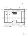
- FIG. 4 is a cross-sectional view showing an outline of the measuring device 1A according to the modified example.
- the end face 13a on the upstream side of the convex portion 13A has a gradient such that the opening area of the hollow portion (small diameter portion 14A) of the convex portion 13A gradually decreases toward the downstream side. Since the convex portion 13A has a substantially annular shape, the end surface 13a is sloped by taping the upstream side of the convex portion 13A. As a result, the flow of hydraulic oil is less likely to be disturbed and the generation of air bubbles can be prevented as compared with the case where the end face 13a is not sloped.
- the end face 13a in the cross-sectional view is a flat surface, but the end face 13a in the cross-sectional view may be a curved surface or may have a curved surface in part.
- the light irradiation unit 22 and the light receiving unit 23 are used as the measuring unit for measuring the liquid flowing inside the hollow portion 21a, but the measuring unit is not limited to this form.
- an image processing sensor such as a CMOS sensor may be used as a measuring unit, and the image processing sensor may be used to image the liquid flowing through the bypass flow path.
- the length of the bypass flow path (second flow path) is longer than the length of the throttle portion.
- the measuring device 2 according to the second embodiment will be described.
- the same parts as those in the first embodiment are designated by the same reference numerals, and the description thereof will be omitted.
- FIG. 5 is a cross-sectional view showing an outline of the measuring device 2.
- the measuring device 2 has a housing 10A attached to a pipe (not shown).
- the housing 10A has a linear flow path hole 12 that penetrates the housing 10A along the y direction.
- the housing 10A has a convex portion 13B provided so as to project inside the flow path hole 12.
- the convex portion 13B provides the flow path hole 12 with a small diameter portion 14B that functions as a diaphragm.
- the hollow portion of the convex portion 13B is the main flow path.
- the convex portion 13B is adjacent to the convex portion 13C having a substantially annular shape and the convex portion 13C, and the shape when viewed along the flow direction (y direction) of the liquid in the flow path hole 12 is a substantially circular ring shape. It has convex portions 13D and 13E.
- the convex portions 13C, 13D, 13E are provided with linear through holes 15A, 15B that penetrate the convex portions 13C, 13D, 13E along the y direction.
- the lengths of the through holes 15A and 15B are longer than the length of the convex portion 13C.
- a transparent linear glass tube 21A is provided inside the through hole 15B.
- the inside of the through hole 15B is not limited to the glass tube 21A, and for example, a transparent resin tube may be provided inside the through hole 15B.
- the inner diameter of the hollow portion 21b of the glass tube 21A is substantially the same as the inner diameter of the through hole 15A, and when the glass tube 21A is provided inside the through hole 15B, the through hole 15A and the hollow portion 21b communicate with each other. That is, the through hole 15A and the hollow portion 21b are linear through holes (corresponding to the second flow path) penetrating the convex portion 16 and are bypass flow paths through which a part of the hydraulic oil flowing through the flow path hole 12A flows. is there.
- the inner diameters of the through hole 15A and the hollow portion 21b are smaller than the inner diameter of the flow path hole 12.
- the through hole 15A and the hollow portion 21b are substantially parallel to the flow path hole 12, and the flow direction of the hydraulic oil in the hollow portion 21b is substantially the same as the flow direction (y direction) of the hydraulic oil in the flow path hole 12.
- the upstream end of the bypass flow path (through hole 15A and hollow portion 21b), that is, the upstream end of the convex portion 13D is located upstream of the upstream end of the convex portion 13C. Further, the upstream end of the convex portion 13C in the flow direction is arranged on the upstream side in the flow direction from the center of the glass tube 21A.
- the convex portion 13B is provided with a concave portion 17.
- the recess 17 is provided on the upper surface (+ z side surface) 10c of the housing 10A and is connected to the hollow portion of the insertion portion 11.
- the glass tube 21A penetrates the recess 17 in the y direction.
- FIG. 6 is a cross-sectional view taken along the line CC of FIG.
- the light irradiation unit 22 and the light receiving unit 23 are provided inside the recess 17.
- the light receiving unit 23 is provided so as to face the light irradiation unit 22 with the glass tube 21A interposed therebetween.
- the light emitted from the light irradiation unit 22 is applied to the hydraulic oil flowing in the hollow portion 21b. Most of the light (light that has passed through the hydraulic oil) that is irradiated from the light irradiation unit 22 and is not reflected by the impurity particles contained in the hydraulic oil in the hollow portion 21b is received by the light receiving unit 23.
- the alternate long and short dash arrow in FIG. 5 indicates the flow of hydraulic oil. A part of the hydraulic oil flowing through the flow path hole 12 flows into the hollow portion 21b.
- the small diameter portion 14B is provided at a position overlapping the glass tube 21A in a plan view, one of the hydraulic oils flowing through the main flow path (flow path hole 12) due to the pressure difference between the upstream side and the downstream side of the small diameter portion 14B.
- the portion flows into the bypass flow path (through hole 15A and hollow portion 21b). Since the through hole 15A and the hollow portion 21b are provided inside the convex portions 13C, 13D, and 13E protruding inside the flow path hole 12, a part of the hydraulic oil flowing through the flow path hole 12 is provided through the through hole 15A and the through hole 21b.
- the direction of the hydraulic oil flow does not change abruptly, and the generation of air bubbles can be prevented.
- the hydraulic oil flowing through the through hole 15A and the hollow portion 21b joins the hydraulic oil flowing through the flow path hole 12 on the downstream side of the small diameter portion 14B.
- a part of the hydraulic oil flowing through the flow path hole 12 is allowed to flow through the through hole 15A and the hollow portion 21b, and the degree of contamination of the hydraulic oil can be measured by the light irradiation unit 22 and the light receiving unit 23. .. Further, in order to prevent the generation of air bubbles without suddenly changing the direction of the hydraulic oil flow when the hydraulic oil is flowed through the through hole 15A and the hollow portion 21b, air bubbles are generated when measuring the degree of contamination of the hydraulic oil. It is possible to prevent erroneous detection as dust and improve the measurement accuracy.
- the lengths of the through hole 15A and the hollow portion 21b in the y direction are made longer than the length of the small diameter portion 14B, and the end of the through hole 15A on the upstream side in the flow direction is the flow direction of the convex portion 13C.
- the hydraulic oil flowing into the through hole 15A and the hollow portion 21b is less likely to be affected by the turbulence of the flow due to the convex portion 13C, and air bubbles are mixed in the hollow portion 21b. It is possible to prevent a decrease in measurement accuracy due to the above.
- the through hole 15A and the hollow portion 21b are used as the bypass flow path, but the through hole 15A may be eliminated and the hollow portion 21b may be used as the bypass flow path.
- the center of the convex portion 13B in the y direction and the center of the glass tube 21A in the y direction substantially coincide with each other, but the upstream end of the convex portion 13B in the flow direction is from the center of the glass tube 21A. If it is arranged on the upstream side in the flow direction, the position and length of the convex portion 13B in the y direction are not limited to this.
- the convex portions 13D and 13E are provided on the upstream side and the downstream side of the convex portion 13C, respectively, but the convex portion 13F is not essential, and at least the convex portion 13D is on the upstream side of the convex portion 13C. It suffices if it is provided in.
- the end face on the upstream side of the convex portion 13D is substantially orthogonal to the central axis of the flow path hole 12, but the end face on the upstream side of the convex portion 13D has an opening area of the flow path hole 12. It may have a gradient that gradually decreases. Further, the upstream side of the convex portion 13C may also have a gradient such that the opening area of the flow path hole 12 gradually decreases.
- the third embodiment of the present invention is a mode in which the central axis of the flow path hole and the central axis of the small diameter portion do not match.
- the measuring device 3 according to the third embodiment will be described.
- the same parts as those in the first embodiment are designated by the same reference numerals, and the description thereof will be omitted.
- FIG. 7 is a cross-sectional view showing an outline of the measuring device 3.
- the measuring device 3 has a housing 10B attached to a pipe (not shown).
- the housing 10B has a flow path hole 12A which is a linear through hole penetrating the housing 10B along the y direction.
- the housing 10B has a convex portion 13F provided so as to project inside the flow path hole 12A.
- the hollow portion of the convex portion 13F is a small diameter portion 14C that functions as a diaphragm.
- the inside of the convex portion 13F is the main flow path.
- the central axis of the small diameter portion 14C is along the y direction, but does not coincide with the central axis of the flow path hole 12A.
- a linear through hole 15C that penetrates the convex portion 13F along the y direction is provided inside the convex portion 13F.
- a transparent glass tube 21B is provided inside the through hole 15C.
- the hollow portion 21c of the glass tube 21B is substantially parallel to the flow path hole 12A, and the inner diameter is smaller than the diameter of the flow path hole 12A and the small diameter portion 14C.
- the inside of the hollow portion 21c is a bypass flow path.
- the inner diameter of the bypass flow path (hollow portion 21c) can be increased.
- FIG. 8 is a cross-sectional view showing an outline of the measuring device 3A having a diaphragm inside the main flow path.
- the housing 10C has a substantially ring-shaped convex portion 13G provided so as to project inside the small diameter portion 14C.
- the convex portion 13G is provided on the inner peripheral surface of the convex portion 13F.
- the hollow portion of the convex portion 13G is a small diameter portion 14D that functions as a diaphragm. This makes it easier for the hydraulic oil to flow into the bypass flow path.
- the convex portion 13G has a substantially annular shape, but the shape of the convex portion 13G is not limited to the substantially annular shape.
- a fourth embodiment of the present invention is a form in which valves are provided in the main flow path and the bypass flow path.
- the measuring device 4 according to the fourth embodiment will be described.
- the same parts as those in the first to third embodiments are designated by the same reference numerals, and the description thereof will be omitted.
- FIG. 9 is a cross-sectional view showing an outline of the measuring device 4.
- the measuring device 4 has a housing 10B provided with a flow path hole 12A and a convex portion 13F. Valves 25 and 26 are provided on the convex portion 13F.
- the valve 25 is provided so as to cover the small diameter portion 14C (main flow path).
- the valve 25 mainly has a valve seat member 25a, a valve body 25b, and a valve rod 25c.
- the valve seat member 25a has a substantially cylindrical insertion portion 25d inserted inside the small diameter portion 14C, and a flange portion 25e provided at the end of the insertion portion 25d.
- a male screw portion is formed around the insertion portion 25d, and a female screw portion is formed on the inner peripheral surface of the convex portion 13F.
- the insertion portion 25d is inserted into the small diameter portion 14C, and the flange portion 25e comes into contact with the side surface of the convex portion 13F.
- the insertion portion 25d is provided with a plurality of holes 25f that serve as flow paths for the liquid along the axial direction.
- the valve seat member 25a is provided with a valve rod 25c along the y direction.
- the valve rod 25c is provided with a valve body 25b.
- the valve body 25b is a plate-shaped member and has a hole into which the valve rod 25c is inserted.
- the valve body 25b is slidable along the valve rod 25c.
- a fixing portion 25g is provided near the end of the valve rod 25c on the opposite side of the valve seat member 25a.
- An elastic member 25h such as a coil spring is provided between the fixed portion 25g and the valve body 25b.
- the valve body 25b is pressed against the end surface (corresponding to the valve seat) of the flange portion 25e by the urging force of the elastic member 25h. Normally, the valve 25 is in a closed state in which the valve body 25b abuts on the flange portion 25e, and the valve body 25b covers the small diameter portion 14C.
- a transparent glass tube 21C is provided inside the through hole 15C.
- the only difference between the glass tube 21B and the glass tube 21C is the length.
- the hollow portion 21d of the glass tube 21C is a bypass flow path that is substantially parallel to the flow path hole 12A and whose inner diameter is smaller than the diameter of the flow path hole 12A and the small diameter portion 14C.
- the valve 26 is provided so as to cover the through hole 15C.
- the valve 26 mainly has a valve seat member 26a, a valve body 26b, and a valve rod 26c.
- the valve seat member 26a has a substantially cylindrical insertion portion 26d inserted into the hollow portion 21c, and a flange portion 26e provided at the end of the insertion portion 26d.
- a male threaded portion is formed around the insertion portion 26d, and a female threaded portion is formed on the inner peripheral surface of the through hole 15C.
- the insertion portion 26d is inserted into the through hole 15C, and the flange portion 26e abuts on the side surface of the convex portion 13F.
- the insertion portion 26d is provided with a plurality of holes 26f that serve as flow paths for the liquid along the axial direction.
- the valve seat member 26a is provided with a valve rod 26c along the y direction.
- the valve rod 26c is provided with a valve body 26b.
- the valve body 26b is a plate-shaped member and has a hole into which the valve rod 26c is inserted.
- the valve body 26b is slidable along the valve rod 26c.
- a fixing portion 26g is provided near the end of the valve rod 26c on the opposite side of the valve seat member 26a. Further, an elastic member 26h such as a coil spring is provided between the fixing portion 26g and the valve body 26b. The valve body 26b is pressed against the end surface (corresponding to the valve seat) of the flange portion 26e by the urging force of the elastic member 26h. Normally, the valve 26 is in a closed state in which the valve body 26b abuts on the flange portion 26e, and the valve body 26b covers the hollow portion 21d.
- FIG. 10 is a cross-sectional view showing an outline of the measuring device 4 when the valves 25 and 26 are opened.
- the hydraulic oil presses the valve body 25b against the urging force of the elastic member 25h.
- the valve body 25b is separated from the end surface of the flange portion 25e to open the valve 25, the upstream side and the downstream side of the valve 25 communicate with each other through the hole 25f, and hydraulic oil flows through the main flow path.
- the hydraulic oil presses the valve body 26b against the urging force of the elastic member 26h.
- the valve body 26b is separated from the end surface of the flange portion 26e to open the valve 25, the upstream side and the downstream side of the valve 26 communicate with each other through the hole 26f, and hydraulic oil flows through the bypass flow path.
- FIG. 10 illustrates the case where both valves 25 and 26 are open, it is possible that only one of the valves 25 and 26 is open.
- the amount of liquid flowing through the main flow path and the bypass flow path can be adjusted by providing the valves 25 and 26 in the main flow path and the bypass flow path, respectively.
- the flow rate of the liquid flowing through the bypass flow path is kept at about 1 to 5 liters per minute, but if the valves 25 and 26 are not provided, it depends on the operating condition of the engine and temperature fluctuations. The flow rate may change and the flow rate of the liquid flowing through the bypass flow path may not be kept constant.
- the valves 25 and 26 as in the present embodiment, the amount of liquid flowing through the main flow path and the bypass flow path can be adjusted.
- valve 25 even if the total flow rate is small, it can be adjusted so that a constant flow rate of oil can flow through the bypass flow path.
- valve 26 when the flow rate of the bypass flow path is not stable only with the valve 25 (for example, when the flow rate is large), the flow rate of the liquid flowing through the bypass flow path is measured by the measuring unit (light irradiation unit 22 and the light receiving unit). The flow rate can be adjusted so that 23) is within the measurable flow rate range.
- valves 25 and 26 are provided in the main flow path and the bypass flow path, respectively, but only one of the valves 25 and 26 may be provided.
- FIG. 11 is a cross-sectional view showing an outline of the measuring device 4A according to the modified example in which the valve 25 is provided in the main flow path.
- FIG. 12 is a cross-sectional view showing an outline of the measuring device 4B according to the modified example in which the valve 26 is provided in the bypass flow path. Even in such a case, the amount of liquid flowing through the main flow path and the bypass flow path can be adjusted.
- “abbreviation” is a concept that includes not only the case where the identity is exactly the same but also an error or deformation to the extent that the identity is not lost.
- substantially orthogonal is not limited to the case of being strictly orthogonal, and is a concept including an error of, for example, several degrees.
- orthogonality, parallelism, coincidence, etc. not only the case of strictly orthogonality, parallelism, coincidence, etc., but also the case of substantially parallelism, substantially orthogonality, substantially coincidence, etc. shall be included.
- the "neighborhood” means to include a region in a certain range (which can be arbitrarily determined) near the reference position. For example, in the case of the vicinity of an edge, it is a concept indicating that it is a region of a certain range near the edge and may or may not include the edge.
Landscapes
- Physics & Mathematics (AREA)
- Chemical & Material Sciences (AREA)
- Health & Medical Sciences (AREA)
- Life Sciences & Earth Sciences (AREA)
- Analytical Chemistry (AREA)
- Biochemistry (AREA)
- General Health & Medical Sciences (AREA)
- General Physics & Mathematics (AREA)
- Immunology (AREA)
- Pathology (AREA)
- Engineering & Computer Science (AREA)
- Spectroscopy & Molecular Physics (AREA)
- Dispersion Chemistry (AREA)
- Medicinal Chemistry (AREA)
- General Chemical & Material Sciences (AREA)
- Oil, Petroleum & Natural Gas (AREA)
- Food Science & Technology (AREA)
- Chemical Kinetics & Catalysis (AREA)
- Mathematical Physics (AREA)
- Theoretical Computer Science (AREA)
- Measuring Volume Flow (AREA)
- Optical Measuring Cells (AREA)
- Investigating Or Analysing Materials By Optical Means (AREA)
- Investigating Materials By The Use Of Optical Means Adapted For Particular Applications (AREA)
Priority Applications (1)
| Application Number | Priority Date | Filing Date | Title |
|---|---|---|---|
| JP2021545559A JP7583725B2 (ja) | 2019-09-12 | 2020-09-09 | 測定装置 |
Applications Claiming Priority (2)
| Application Number | Priority Date | Filing Date | Title |
|---|---|---|---|
| JP2019166414 | 2019-09-12 | ||
| JP2019-166414 | 2019-09-12 |
Publications (1)
| Publication Number | Publication Date |
|---|---|
| WO2021049512A1 true WO2021049512A1 (ja) | 2021-03-18 |
Family
ID=74865696
Family Applications (1)
| Application Number | Title | Priority Date | Filing Date |
|---|---|---|---|
| PCT/JP2020/034067 Ceased WO2021049512A1 (ja) | 2019-09-12 | 2020-09-09 | 測定装置 |
Country Status (3)
| Country | Link |
|---|---|
| JP (1) | JP7583725B2 (https=) |
| CN (2) | CN112485164A (https=) |
| WO (1) | WO2021049512A1 (https=) |
Cited By (2)
| Publication number | Priority date | Publication date | Assignee | Title |
|---|---|---|---|---|
| JP2025092397A (ja) * | 2023-12-08 | 2025-06-19 | Wota株式会社 | フローセル |
| WO2026063114A1 (ja) * | 2024-09-17 | 2026-03-26 | ダイキン工業株式会社 | 液体状態センサ、液状態判定装置、及び油圧ユニット |
Citations (6)
| Publication number | Priority date | Publication date | Assignee | Title |
|---|---|---|---|---|
| JPS53116187A (en) * | 1977-03-14 | 1978-10-11 | Bindicator Co | Fluid characteristic measuring device |
| JPH0231310U (https=) * | 1988-08-23 | 1990-02-27 | ||
| JPH0581696U (ja) * | 1992-04-09 | 1993-11-05 | 福井機械株式会社 | プレス機械の作動油汚染監視装置 |
| JPH11235097A (ja) * | 1998-02-20 | 1999-08-27 | Hitachi Ltd | 劣化診断装置を具備した原動電動装置 |
| JP2000009675A (ja) * | 1998-06-25 | 2000-01-14 | Matsushita Electric Works Ltd | 水質検出器 |
| JP2009069097A (ja) * | 2007-09-18 | 2009-04-02 | Nippon Soken Inc | 粒子濃度測定装置 |
Family Cites Families (7)
| Publication number | Priority date | Publication date | Assignee | Title |
|---|---|---|---|---|
| JPH0231316U (https=) * | 1988-08-19 | 1990-02-27 | ||
| JP3193837B2 (ja) * | 1994-10-18 | 2001-07-30 | 株式会社日立製作所 | 発熱抵抗式流量測定装置 |
| EP1418407B1 (en) * | 2001-07-18 | 2013-06-19 | Hitachi, Ltd. | Equipment for measuring gas flow rate |
| JP4168417B2 (ja) * | 2002-11-18 | 2008-10-22 | 株式会社山武 | 流体検出装置 |
| JP2009014601A (ja) * | 2007-07-06 | 2009-01-22 | Yamatake Corp | 流量計 |
| CN204457688U (zh) * | 2014-12-16 | 2015-07-08 | 中国石油天然气股份有限公司 | 配水装置 |
| JP2017003482A (ja) * | 2015-06-12 | 2017-01-05 | ヤマシンフィルタ株式会社 | 測定装置 |
-
2020
- 2020-09-03 CN CN202010915670.1A patent/CN112485164A/zh active Pending
- 2020-09-03 CN CN202021901009.7U patent/CN212722497U/zh active Active
- 2020-09-09 JP JP2021545559A patent/JP7583725B2/ja active Active
- 2020-09-09 WO PCT/JP2020/034067 patent/WO2021049512A1/ja not_active Ceased
Patent Citations (6)
| Publication number | Priority date | Publication date | Assignee | Title |
|---|---|---|---|---|
| JPS53116187A (en) * | 1977-03-14 | 1978-10-11 | Bindicator Co | Fluid characteristic measuring device |
| JPH0231310U (https=) * | 1988-08-23 | 1990-02-27 | ||
| JPH0581696U (ja) * | 1992-04-09 | 1993-11-05 | 福井機械株式会社 | プレス機械の作動油汚染監視装置 |
| JPH11235097A (ja) * | 1998-02-20 | 1999-08-27 | Hitachi Ltd | 劣化診断装置を具備した原動電動装置 |
| JP2000009675A (ja) * | 1998-06-25 | 2000-01-14 | Matsushita Electric Works Ltd | 水質検出器 |
| JP2009069097A (ja) * | 2007-09-18 | 2009-04-02 | Nippon Soken Inc | 粒子濃度測定装置 |
Cited By (3)
| Publication number | Priority date | Publication date | Assignee | Title |
|---|---|---|---|---|
| JP2025092397A (ja) * | 2023-12-08 | 2025-06-19 | Wota株式会社 | フローセル |
| JP7772410B2 (ja) | 2023-12-08 | 2025-11-18 | Wota株式会社 | フローセル |
| WO2026063114A1 (ja) * | 2024-09-17 | 2026-03-26 | ダイキン工業株式会社 | 液体状態センサ、液状態判定装置、及び油圧ユニット |
Also Published As
| Publication number | Publication date |
|---|---|
| CN212722497U (zh) | 2021-03-16 |
| CN112485164A (zh) | 2021-03-12 |
| JP7583725B2 (ja) | 2024-11-14 |
| JPWO2021049512A1 (https=) | 2021-03-18 |
Similar Documents
| Publication | Publication Date | Title |
|---|---|---|
| WO2021049512A1 (ja) | 測定装置 | |
| US9170180B2 (en) | Particle number counting apparatus | |
| US7891256B2 (en) | Differential-pressure flow meter having a main control board in a space in a base member | |
| US20150101419A1 (en) | Phase Detection in Multi-Phase Fluids | |
| KR101750118B1 (ko) | 광학측정장치 | |
| CN107735669A (zh) | 测定装置 | |
| JP7563795B2 (ja) | 濃度測定装置 | |
| KR102612893B1 (ko) | 압력 검출 장치 | |
| JP6243762B2 (ja) | 圧力センサ | |
| JP2009063400A (ja) | 差圧式光ファイバ流量センサ及びそれを使った流量検知システム | |
| KR101613479B1 (ko) | 압력 센서 | |
| JP7699819B2 (ja) | 濃度測定装置 | |
| US20110051140A1 (en) | Full-flow sensor for contamination in fluids | |
| US11255774B2 (en) | Gas sensor | |
| CN102853879B (zh) | 液体传感器 | |
| US12019016B2 (en) | Light scattering detectors and sample cells for the same | |
| JP2009063399A (ja) | 光ファイバ流量センサ及びそれを使った流量検知システム | |
| JP2009133747A (ja) | 流路センサ | |
| US20190033108A1 (en) | Thermal flowmeter | |
| WO2023047870A1 (ja) | 流体制御装置及びガス供給システム | |
| JPWO2008142922A1 (ja) | 流路センサ及びそれに用いるチューブ固定具 | |
| JP2008304396A (ja) | 流量計 |
Legal Events
| Date | Code | Title | Description |
|---|---|---|---|
| 121 | Ep: the epo has been informed by wipo that ep was designated in this application |
Ref document number: 20862357 Country of ref document: EP Kind code of ref document: A1 |
|
| ENP | Entry into the national phase |
Ref document number: 2021545559 Country of ref document: JP Kind code of ref document: A |
|
| NENP | Non-entry into the national phase |
Ref country code: DE |
|
| 122 | Ep: pct application non-entry in european phase |
Ref document number: 20862357 Country of ref document: EP Kind code of ref document: A1 |