WO2021049512A1 - Measurement apparatus - Google Patents
Measurement apparatus Download PDFInfo
- Publication number
- WO2021049512A1 WO2021049512A1 PCT/JP2020/034067 JP2020034067W WO2021049512A1 WO 2021049512 A1 WO2021049512 A1 WO 2021049512A1 JP 2020034067 W JP2020034067 W JP 2020034067W WO 2021049512 A1 WO2021049512 A1 WO 2021049512A1
- Authority
- WO
- WIPO (PCT)
- Prior art keywords
- hole
- convex portion
- flow path
- hydraulic oil
- measuring device
- Prior art date
Links
- 238000005259 measurement Methods 0.000 title description 8
- 239000007788 liquid Substances 0.000 claims abstract description 29
- 230000000149 penetrating effect Effects 0.000 claims abstract description 10
- 238000011144 upstream manufacturing Methods 0.000 claims description 34
- 230000007423 decrease Effects 0.000 claims description 8
- 230000002093 peripheral effect Effects 0.000 claims description 6
- 239000010720 hydraulic oil Substances 0.000 abstract description 66
- 238000011109 contamination Methods 0.000 abstract description 11
- 239000011521 glass Substances 0.000 description 27
- 238000003780 insertion Methods 0.000 description 16
- 230000037431 insertion Effects 0.000 description 16
- 238000001514 detection method Methods 0.000 description 2
- 239000000428 dust Substances 0.000 description 2
- 239000012535 impurity Substances 0.000 description 2
- 238000000034 method Methods 0.000 description 2
- 238000012986 modification Methods 0.000 description 2
- 230000004048 modification Effects 0.000 description 2
- 239000002245 particle Substances 0.000 description 2
- 238000012545 processing Methods 0.000 description 2
- 239000011347 resin Substances 0.000 description 2
- 229920005989 resin Polymers 0.000 description 2
- 230000005540 biological transmission Effects 0.000 description 1
- 235000019646 color tone Nutrition 0.000 description 1
- 238000010276 construction Methods 0.000 description 1
- 238000013461 design Methods 0.000 description 1
- 230000006866 deterioration Effects 0.000 description 1
- 239000010419 fine particle Substances 0.000 description 1
- 239000003921 oil Substances 0.000 description 1
Images


Classifications
-
- G—PHYSICS
- G01—MEASURING; TESTING
- G01N—INVESTIGATING OR ANALYSING MATERIALS BY DETERMINING THEIR CHEMICAL OR PHYSICAL PROPERTIES
- G01N15/00—Investigating characteristics of particles; Investigating permeability, pore-volume or surface-area of porous materials
- G01N15/02—Investigating particle size or size distribution
- G01N15/0205—Investigating particle size or size distribution by optical means
-
- G—PHYSICS
- G01—MEASURING; TESTING
- G01N—INVESTIGATING OR ANALYSING MATERIALS BY DETERMINING THEIR CHEMICAL OR PHYSICAL PROPERTIES
- G01N15/00—Investigating characteristics of particles; Investigating permeability, pore-volume or surface-area of porous materials
- G01N15/02—Investigating particle size or size distribution
-
- G—PHYSICS
- G01—MEASURING; TESTING
- G01N—INVESTIGATING OR ANALYSING MATERIALS BY DETERMINING THEIR CHEMICAL OR PHYSICAL PROPERTIES
- G01N21/00—Investigating or analysing materials by the use of optical means, i.e. using sub-millimetre waves, infrared, visible or ultraviolet light
- G01N21/01—Arrangements or apparatus for facilitating the optical investigation
- G01N21/03—Cuvette constructions
- G01N21/05—Flow-through cuvettes
-
- G—PHYSICS
- G01—MEASURING; TESTING
- G01N—INVESTIGATING OR ANALYSING MATERIALS BY DETERMINING THEIR CHEMICAL OR PHYSICAL PROPERTIES
- G01N21/00—Investigating or analysing materials by the use of optical means, i.e. using sub-millimetre waves, infrared, visible or ultraviolet light
- G01N21/17—Systems in which incident light is modified in accordance with the properties of the material investigated
- G01N21/25—Colour; Spectral properties, i.e. comparison of effect of material on the light at two or more different wavelengths or wavelength bands
- G01N21/27—Colour; Spectral properties, i.e. comparison of effect of material on the light at two or more different wavelengths or wavelength bands using photo-electric detection ; circuits for computing concentration
-
- G—PHYSICS
- G01—MEASURING; TESTING
- G01N—INVESTIGATING OR ANALYSING MATERIALS BY DETERMINING THEIR CHEMICAL OR PHYSICAL PROPERTIES
- G01N21/00—Investigating or analysing materials by the use of optical means, i.e. using sub-millimetre waves, infrared, visible or ultraviolet light
- G01N21/17—Systems in which incident light is modified in accordance with the properties of the material investigated
- G01N21/59—Transmissivity
-
- G—PHYSICS
- G01—MEASURING; TESTING
- G01N—INVESTIGATING OR ANALYSING MATERIALS BY DETERMINING THEIR CHEMICAL OR PHYSICAL PROPERTIES
- G01N21/00—Investigating or analysing materials by the use of optical means, i.e. using sub-millimetre waves, infrared, visible or ultraviolet light
- G01N21/84—Systems specially adapted for particular applications
- G01N21/85—Investigating moving fluids or granular solids
-
- G—PHYSICS
- G01—MEASURING; TESTING
- G01N—INVESTIGATING OR ANALYSING MATERIALS BY DETERMINING THEIR CHEMICAL OR PHYSICAL PROPERTIES
- G01N33/00—Investigating or analysing materials by specific methods not covered by groups G01N1/00 - G01N31/00
- G01N33/26—Oils; Viscous liquids; Paints; Inks
- G01N33/28—Oils, i.e. hydrocarbon liquids
Definitions
- the present invention relates to a measuring device.
- Patent Document 1 discloses a photometric device provided with a photometric unit for observing fine particles and color tones (that is, contamination or deterioration of the hydraulic oil) in the circulation path of the hydraulic oil used as a power transmission medium for a hydraulic device. There is.
- Patent Document 1 it is necessary to secure a space for providing a photometric unit (sensor) and a branch flow path in advance in the flood control device, and the position where the sensor and the branch flow path are provided is limited. In addition, it is not easy to attach / detach the sensor or the branch flow path, and the maintainability is poor.
- the present invention has been made in view of such circumstances, and provides a measuring device capable of providing a measuring device for measuring the degree of contamination of a liquid such as hydraulic oil at an arbitrary position and having high maintainability.
- a measuring device capable of providing a measuring device for measuring the degree of contamination of a liquid such as hydraulic oil at an arbitrary position and having high maintainability. The purpose.
- the measuring device has, for example, a first through hole through which a liquid flows, a convex portion provided so as to project into the first through hole, and the convex portion.
- a first through hole and a second through hole are provided inside the housing, and the measuring unit measures the liquid flowing inside the second through hole.
- a convex portion is provided so as to project inside the first through hole (main flow path) which is a through hole penetrating the housing, and the second through hole (bypass flow path) penetrating the convex portion is provided.
- the inner diameter is smaller than the inner diameter of the first through hole.
- the convex portion has a substantially annular shape, and the length of the convex portion and the length of the second through hole may be substantially the same.
- the measuring device can be made into a simple shape and the housing can be miniaturized.
- the convex portion is adjacent to the first convex portion having a substantially annular shape and the first convex portion, and the shape when viewed along the flow direction of the liquid in the first through hole is a substantially partial annular shape.
- the second through hole penetrates the first convex portion and the second convex portion, and in the flow direction, the upstream end of the second convex portion is: It may be located on the upstream side of the upstream end of the first convex portion.
- the end face on the upstream side of the convex portion may have a gradient such that the opening area of the hollow portion of the convex portion gradually decreases toward the downstream.
- At least one of a first valve provided in the convex portion so as to cover the hollow portion of the convex portion and a second valve provided in the convex portion so as to cover the second through hole may be provided. Thereby, the amount of the liquid flowing through the first through hole and the second through hole can be adjusted.
- a third convex portion may be provided on the inner peripheral surface of the convex portion. This makes it easier for the liquid to flow into the second through hole.
- a measuring device for measuring the degree of contamination of a liquid such as hydraulic oil can be provided at an arbitrary position, and maintainability can be improved.
- the measuring device of the present invention is installed, for example, in a hydraulic device of a construction machine (not shown), and is provided in a hydraulic circuit of hydraulic oil supplied to the hydraulic device.
- the hydraulic system includes a filter, a pipe, a tank, a valve (not shown), and the like, and a measuring device is attached to the pipe.
- the hydraulic oil will be described as an example as the liquid to be measured for the degree of contamination, but the liquid to be measured is not limited to the hydraulic oil.
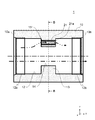
- FIG. 1 is a front view showing an outline of the measuring device 1.
- FIG. 2 is a cross-sectional view taken along the line AA of FIG.
- the measuring device 1 has a housing 10 attached to a pipe (not shown).
- the housing 10 has a substantially rectangular shape, and a substantially box-shaped insertion portion 11 in which a circuit board (not shown) or the like is provided inside is provided on the upper side (+ z side).
- the insertion portion 11 is provided with a connection portion 30 that supplies electric power or the like to a circuit board or the like (not shown). Note that the insertion portion 11 is not shown in FIG.
- a flow path hole 12 which is a linear through hole penetrating the housing 10 is provided inside the housing 10.
- the hydraulic oil flows inside the flow path hole 12 from the front to the back (in the + y direction). That is, the flow direction of the hydraulic oil is the y direction, the ⁇ y direction is the upstream side, and the + y direction is the downstream side. Both ends of the flow path hole 12 are opened to the upstream side surface 10a and the downstream side surface 10b of the housing 10.
- the housing 10 has a substantially ring-shaped convex portion 13 provided so as to project inside the flow path hole 12.
- the convex portion 13 is a diaphragm for narrowing the inner diameter of the flow path hole 12, and the convex portion 13 forms a small diameter portion 14 in the flow path hole 12.
- the hollow portion of the convex portion 13 is the main flow path.
- a linear through hole 15 that penetrates the convex portion 13 along the y direction is provided inside the convex portion 13.
- the through hole 15 and the flow path hole 12 are substantially parallel to each other.
- a transparent glass tube 21 is provided inside the through hole 15.
- the glass tube 21 is inserted inside the through hole 15, but the tube inserted inside the through hole 15 may be transparent and is not limited to the glass tube.
- a transparent resin tube may be inserted inside the through hole 15.
- the glass tube 21 is a linear hollow round bar.
- the hollow portion 21a of the glass tube 21 is a linear through hole penetrating the convex portion 13, is substantially parallel to the flow path hole 12, and has an inner diameter smaller than the diameter of the flow path hole 12 and the small diameter portion 14.
- the inside of the hollow portion 21a is a bypass flow path through which a part of the hydraulic oil flowing inside the flow path hole 12 flows, and when the hydraulic system is operated, about 1 to 5 liters of hydraulic oil flows inside the hollow portion 21a per minute. ..
- the flow direction of the hydraulic oil in the hollow portion 21a is substantially the same as the flow direction (y direction) of the hydraulic oil in the flow path hole 12.
- the small diameter portion 14 is provided at a position overlapping the glass tube 21 (when viewed from the z direction) in a plan view.
- the length of the convex portion 13 and the length of the glass tube 21 (hollow portion 21a) are substantially the same.
- Threaded portions 12a and 12b are provided at both ends of the flow path hole 12, respectively.
- pipes By screwing the screw portions formed in the pipes of the hydraulic circuit (not shown) into the screw portions 12a and 12b, pipes (not shown) are provided on the upstream side and the downstream side of the housing 10 (that is, the measuring device 1). Further, since the screws are used, the housing 10 (measuring device 1) can be easily attached and detached.
- a pipe (not shown) is attached to the housing 10 by using the screw portions 12a and 12b, but the method of attaching the pipe is not limited to this.
- a pipe may be attached to the housing 10 by providing flanges on the surfaces 10a and 10b, respectively, and connecting the flanges with a flange of a pipe (not shown).
- the housing 10 (measuring device 1) can be easily attached and detached.
- FIG. 3 is a cross-sectional view taken along the line BB of FIG.
- the light irradiation unit 22 and the light receiving unit 23 are measuring units for measuring the liquid flowing inside the hollow portion 21a, and are provided on the convex portion 13.
- the light irradiation unit 22 has a light emitting unit (for example, an LED) that irradiates light.
- the light receiving unit 23 receives the light emitted from the light irradiation unit 22, and has a light receiving element (for example, a photodiode) that detects the transmitted light.
- the light receiving unit 23 is provided so as to face the light irradiation unit 22 with the glass tube 21 interposed therebetween.
- the light emitted from the light irradiation unit 22 is applied to the hydraulic oil flowing in the hollow portion 21a.
- Most of the light (light that has passed through the hydraulic oil) that is irradiated from the light irradiation unit 22 and is not reflected by the impurity particles contained in the hydraulic oil in the hollow portion 21a is received by the light receiving unit 23. Since already known techniques can be used for the light irradiation unit 22 and the light receiving unit 23, the description thereof will be omitted.
- the alternate long and short dash arrow in FIG. 2 indicates the flow of hydraulic oil. A part of the hydraulic oil flowing through the flow path hole 12 flows into the hollow portion 21a.
- the convex portion 13 Since the convex portion 13 is provided at a position overlapping the glass tube 21 in a plan view, most of the hydraulic oil flowing through the flow path hole 12 is the main flow path due to the pressure difference between the upstream side and the downstream side of the small diameter portion 14. It flows to (inside the convex portion 13), and a part of the flow flows to the bypass flow path (hollow portion 21a). Since the hollow portion 21a is provided inside the convex portion 13 projecting inside the flow path hole 12, the flow of the hydraulic oil when a part of the hydraulic oil flowing through the flow path hole 12 flows into the hollow portion 21a. The direction of is not changed suddenly. If the direction of the hydraulic oil changes suddenly, the flow may be disturbed and bubbles may be generated. However, in the present embodiment, the bubbles are generated by preventing the direction of the hydraulic oil from changing suddenly. Can be prevented.
- the hydraulic oil flowing through the hollow portion 21a joins the hydraulic oil flowing through the flow path hole 12 on the downstream side of the convex portion 13.
- a part of the hydraulic oil flowing through the flow path hole 12 can be flowed into the hollow portion 21a, and the degree of contamination of the hydraulic oil can be measured by the light irradiation unit 22 and the light receiving unit 23.
- the measuring device 1 for measuring the degree of contamination of a liquid such as hydraulic oil is provided at an arbitrary position. be able to. Further, the measuring device 1 can be installed only by attaching the housing 10 to a pipe or the like, and the housing 10 can be easily attached and detached, so that maintainability can be improved.
- the light irradiation unit 22 and the light receiving unit 23 are used.
- the degree of contamination of hydraulic oil it is possible to prevent erroneous detection of air bubbles as dust and improve the measurement accuracy.
- the measuring device 1 is made into a simple shape by providing the glass tube 21, the light irradiation unit 22, and the light receiving unit 23 on the convex portion 13 protruding inside the flow path hole 12, and the housing.
- the body 10 can be miniaturized.
- the hollow portion of the convex portion 13 is used as the main flow path, but the inner diameter of the main flow path may be variable.
- an orifice having a male screw formed around it and a hole formed in the center is used, and this orifice is screwed into a female screw formed on the inner peripheral surface of the flow path hole 12 or the convex portion 13 to replace the orifice.
- the inner diameter of the main flow path may be changed.
- both end faces of the convex portion 13 are substantially orthogonal to the central axis of the flow path hole 12, but the end faces on the upstream side of the convex portion 13 may have a gradient.
- FIG. 4 is a cross-sectional view showing an outline of the measuring device 1A according to the modified example.
- the end face 13a on the upstream side of the convex portion 13A has a gradient such that the opening area of the hollow portion (small diameter portion 14A) of the convex portion 13A gradually decreases toward the downstream side. Since the convex portion 13A has a substantially annular shape, the end surface 13a is sloped by taping the upstream side of the convex portion 13A. As a result, the flow of hydraulic oil is less likely to be disturbed and the generation of air bubbles can be prevented as compared with the case where the end face 13a is not sloped.
- the end face 13a in the cross-sectional view is a flat surface, but the end face 13a in the cross-sectional view may be a curved surface or may have a curved surface in part.
- the light irradiation unit 22 and the light receiving unit 23 are used as the measuring unit for measuring the liquid flowing inside the hollow portion 21a, but the measuring unit is not limited to this form.
- an image processing sensor such as a CMOS sensor may be used as a measuring unit, and the image processing sensor may be used to image the liquid flowing through the bypass flow path.
- the length of the bypass flow path (second flow path) is longer than the length of the throttle portion.
- the measuring device 2 according to the second embodiment will be described.
- the same parts as those in the first embodiment are designated by the same reference numerals, and the description thereof will be omitted.
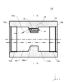
- FIG. 5 is a cross-sectional view showing an outline of the measuring device 2.
- the measuring device 2 has a housing 10A attached to a pipe (not shown).
- the housing 10A has a linear flow path hole 12 that penetrates the housing 10A along the y direction.
- the housing 10A has a convex portion 13B provided so as to project inside the flow path hole 12.
- the convex portion 13B provides the flow path hole 12 with a small diameter portion 14B that functions as a diaphragm.
- the hollow portion of the convex portion 13B is the main flow path.
- the convex portion 13B is adjacent to the convex portion 13C having a substantially annular shape and the convex portion 13C, and the shape when viewed along the flow direction (y direction) of the liquid in the flow path hole 12 is a substantially circular ring shape. It has convex portions 13D and 13E.
- the convex portions 13C, 13D, 13E are provided with linear through holes 15A, 15B that penetrate the convex portions 13C, 13D, 13E along the y direction.
- the lengths of the through holes 15A and 15B are longer than the length of the convex portion 13C.
- a transparent linear glass tube 21A is provided inside the through hole 15B.
- the inside of the through hole 15B is not limited to the glass tube 21A, and for example, a transparent resin tube may be provided inside the through hole 15B.
- the inner diameter of the hollow portion 21b of the glass tube 21A is substantially the same as the inner diameter of the through hole 15A, and when the glass tube 21A is provided inside the through hole 15B, the through hole 15A and the hollow portion 21b communicate with each other. That is, the through hole 15A and the hollow portion 21b are linear through holes (corresponding to the second flow path) penetrating the convex portion 16 and are bypass flow paths through which a part of the hydraulic oil flowing through the flow path hole 12A flows. is there.
- the inner diameters of the through hole 15A and the hollow portion 21b are smaller than the inner diameter of the flow path hole 12.
- the through hole 15A and the hollow portion 21b are substantially parallel to the flow path hole 12, and the flow direction of the hydraulic oil in the hollow portion 21b is substantially the same as the flow direction (y direction) of the hydraulic oil in the flow path hole 12.
- the upstream end of the bypass flow path (through hole 15A and hollow portion 21b), that is, the upstream end of the convex portion 13D is located upstream of the upstream end of the convex portion 13C. Further, the upstream end of the convex portion 13C in the flow direction is arranged on the upstream side in the flow direction from the center of the glass tube 21A.
- the convex portion 13B is provided with a concave portion 17.
- the recess 17 is provided on the upper surface (+ z side surface) 10c of the housing 10A and is connected to the hollow portion of the insertion portion 11.
- the glass tube 21A penetrates the recess 17 in the y direction.
- FIG. 6 is a cross-sectional view taken along the line CC of FIG.
- the light irradiation unit 22 and the light receiving unit 23 are provided inside the recess 17.
- the light receiving unit 23 is provided so as to face the light irradiation unit 22 with the glass tube 21A interposed therebetween.
- the light emitted from the light irradiation unit 22 is applied to the hydraulic oil flowing in the hollow portion 21b. Most of the light (light that has passed through the hydraulic oil) that is irradiated from the light irradiation unit 22 and is not reflected by the impurity particles contained in the hydraulic oil in the hollow portion 21b is received by the light receiving unit 23.
- the alternate long and short dash arrow in FIG. 5 indicates the flow of hydraulic oil. A part of the hydraulic oil flowing through the flow path hole 12 flows into the hollow portion 21b.
- the small diameter portion 14B is provided at a position overlapping the glass tube 21A in a plan view, one of the hydraulic oils flowing through the main flow path (flow path hole 12) due to the pressure difference between the upstream side and the downstream side of the small diameter portion 14B.
- the portion flows into the bypass flow path (through hole 15A and hollow portion 21b). Since the through hole 15A and the hollow portion 21b are provided inside the convex portions 13C, 13D, and 13E protruding inside the flow path hole 12, a part of the hydraulic oil flowing through the flow path hole 12 is provided through the through hole 15A and the through hole 21b.
- the direction of the hydraulic oil flow does not change abruptly, and the generation of air bubbles can be prevented.
- the hydraulic oil flowing through the through hole 15A and the hollow portion 21b joins the hydraulic oil flowing through the flow path hole 12 on the downstream side of the small diameter portion 14B.
- a part of the hydraulic oil flowing through the flow path hole 12 is allowed to flow through the through hole 15A and the hollow portion 21b, and the degree of contamination of the hydraulic oil can be measured by the light irradiation unit 22 and the light receiving unit 23. .. Further, in order to prevent the generation of air bubbles without suddenly changing the direction of the hydraulic oil flow when the hydraulic oil is flowed through the through hole 15A and the hollow portion 21b, air bubbles are generated when measuring the degree of contamination of the hydraulic oil. It is possible to prevent erroneous detection as dust and improve the measurement accuracy.
- the lengths of the through hole 15A and the hollow portion 21b in the y direction are made longer than the length of the small diameter portion 14B, and the end of the through hole 15A on the upstream side in the flow direction is the flow direction of the convex portion 13C.
- the hydraulic oil flowing into the through hole 15A and the hollow portion 21b is less likely to be affected by the turbulence of the flow due to the convex portion 13C, and air bubbles are mixed in the hollow portion 21b. It is possible to prevent a decrease in measurement accuracy due to the above.
- the through hole 15A and the hollow portion 21b are used as the bypass flow path, but the through hole 15A may be eliminated and the hollow portion 21b may be used as the bypass flow path.
- the center of the convex portion 13B in the y direction and the center of the glass tube 21A in the y direction substantially coincide with each other, but the upstream end of the convex portion 13B in the flow direction is from the center of the glass tube 21A. If it is arranged on the upstream side in the flow direction, the position and length of the convex portion 13B in the y direction are not limited to this.
- the convex portions 13D and 13E are provided on the upstream side and the downstream side of the convex portion 13C, respectively, but the convex portion 13F is not essential, and at least the convex portion 13D is on the upstream side of the convex portion 13C. It suffices if it is provided in.
- the end face on the upstream side of the convex portion 13D is substantially orthogonal to the central axis of the flow path hole 12, but the end face on the upstream side of the convex portion 13D has an opening area of the flow path hole 12. It may have a gradient that gradually decreases. Further, the upstream side of the convex portion 13C may also have a gradient such that the opening area of the flow path hole 12 gradually decreases.
- the third embodiment of the present invention is a mode in which the central axis of the flow path hole and the central axis of the small diameter portion do not match.
- the measuring device 3 according to the third embodiment will be described.
- the same parts as those in the first embodiment are designated by the same reference numerals, and the description thereof will be omitted.
- FIG. 7 is a cross-sectional view showing an outline of the measuring device 3.
- the measuring device 3 has a housing 10B attached to a pipe (not shown).
- the housing 10B has a flow path hole 12A which is a linear through hole penetrating the housing 10B along the y direction.
- the housing 10B has a convex portion 13F provided so as to project inside the flow path hole 12A.
- the hollow portion of the convex portion 13F is a small diameter portion 14C that functions as a diaphragm.
- the inside of the convex portion 13F is the main flow path.
- the central axis of the small diameter portion 14C is along the y direction, but does not coincide with the central axis of the flow path hole 12A.
- a linear through hole 15C that penetrates the convex portion 13F along the y direction is provided inside the convex portion 13F.
- a transparent glass tube 21B is provided inside the through hole 15C.
- the hollow portion 21c of the glass tube 21B is substantially parallel to the flow path hole 12A, and the inner diameter is smaller than the diameter of the flow path hole 12A and the small diameter portion 14C.
- the inside of the hollow portion 21c is a bypass flow path.
- the inner diameter of the bypass flow path (hollow portion 21c) can be increased.
- FIG. 8 is a cross-sectional view showing an outline of the measuring device 3A having a diaphragm inside the main flow path.
- the housing 10C has a substantially ring-shaped convex portion 13G provided so as to project inside the small diameter portion 14C.
- the convex portion 13G is provided on the inner peripheral surface of the convex portion 13F.
- the hollow portion of the convex portion 13G is a small diameter portion 14D that functions as a diaphragm. This makes it easier for the hydraulic oil to flow into the bypass flow path.
- the convex portion 13G has a substantially annular shape, but the shape of the convex portion 13G is not limited to the substantially annular shape.
- a fourth embodiment of the present invention is a form in which valves are provided in the main flow path and the bypass flow path.
- the measuring device 4 according to the fourth embodiment will be described.
- the same parts as those in the first to third embodiments are designated by the same reference numerals, and the description thereof will be omitted.
- FIG. 9 is a cross-sectional view showing an outline of the measuring device 4.
- the measuring device 4 has a housing 10B provided with a flow path hole 12A and a convex portion 13F. Valves 25 and 26 are provided on the convex portion 13F.
- the valve 25 is provided so as to cover the small diameter portion 14C (main flow path).
- the valve 25 mainly has a valve seat member 25a, a valve body 25b, and a valve rod 25c.
- the valve seat member 25a has a substantially cylindrical insertion portion 25d inserted inside the small diameter portion 14C, and a flange portion 25e provided at the end of the insertion portion 25d.
- a male screw portion is formed around the insertion portion 25d, and a female screw portion is formed on the inner peripheral surface of the convex portion 13F.
- the insertion portion 25d is inserted into the small diameter portion 14C, and the flange portion 25e comes into contact with the side surface of the convex portion 13F.
- the insertion portion 25d is provided with a plurality of holes 25f that serve as flow paths for the liquid along the axial direction.
- the valve seat member 25a is provided with a valve rod 25c along the y direction.
- the valve rod 25c is provided with a valve body 25b.
- the valve body 25b is a plate-shaped member and has a hole into which the valve rod 25c is inserted.
- the valve body 25b is slidable along the valve rod 25c.
- a fixing portion 25g is provided near the end of the valve rod 25c on the opposite side of the valve seat member 25a.
- An elastic member 25h such as a coil spring is provided between the fixed portion 25g and the valve body 25b.
- the valve body 25b is pressed against the end surface (corresponding to the valve seat) of the flange portion 25e by the urging force of the elastic member 25h. Normally, the valve 25 is in a closed state in which the valve body 25b abuts on the flange portion 25e, and the valve body 25b covers the small diameter portion 14C.
- a transparent glass tube 21C is provided inside the through hole 15C.
- the only difference between the glass tube 21B and the glass tube 21C is the length.
- the hollow portion 21d of the glass tube 21C is a bypass flow path that is substantially parallel to the flow path hole 12A and whose inner diameter is smaller than the diameter of the flow path hole 12A and the small diameter portion 14C.
- the valve 26 is provided so as to cover the through hole 15C.
- the valve 26 mainly has a valve seat member 26a, a valve body 26b, and a valve rod 26c.
- the valve seat member 26a has a substantially cylindrical insertion portion 26d inserted into the hollow portion 21c, and a flange portion 26e provided at the end of the insertion portion 26d.
- a male threaded portion is formed around the insertion portion 26d, and a female threaded portion is formed on the inner peripheral surface of the through hole 15C.
- the insertion portion 26d is inserted into the through hole 15C, and the flange portion 26e abuts on the side surface of the convex portion 13F.
- the insertion portion 26d is provided with a plurality of holes 26f that serve as flow paths for the liquid along the axial direction.
- the valve seat member 26a is provided with a valve rod 26c along the y direction.
- the valve rod 26c is provided with a valve body 26b.
- the valve body 26b is a plate-shaped member and has a hole into which the valve rod 26c is inserted.
- the valve body 26b is slidable along the valve rod 26c.
- a fixing portion 26g is provided near the end of the valve rod 26c on the opposite side of the valve seat member 26a. Further, an elastic member 26h such as a coil spring is provided between the fixing portion 26g and the valve body 26b. The valve body 26b is pressed against the end surface (corresponding to the valve seat) of the flange portion 26e by the urging force of the elastic member 26h. Normally, the valve 26 is in a closed state in which the valve body 26b abuts on the flange portion 26e, and the valve body 26b covers the hollow portion 21d.
- FIG. 10 is a cross-sectional view showing an outline of the measuring device 4 when the valves 25 and 26 are opened.
- the hydraulic oil presses the valve body 25b against the urging force of the elastic member 25h.
- the valve body 25b is separated from the end surface of the flange portion 25e to open the valve 25, the upstream side and the downstream side of the valve 25 communicate with each other through the hole 25f, and hydraulic oil flows through the main flow path.
- the hydraulic oil presses the valve body 26b against the urging force of the elastic member 26h.
- the valve body 26b is separated from the end surface of the flange portion 26e to open the valve 25, the upstream side and the downstream side of the valve 26 communicate with each other through the hole 26f, and hydraulic oil flows through the bypass flow path.
- FIG. 10 illustrates the case where both valves 25 and 26 are open, it is possible that only one of the valves 25 and 26 is open.
- the amount of liquid flowing through the main flow path and the bypass flow path can be adjusted by providing the valves 25 and 26 in the main flow path and the bypass flow path, respectively.
- the flow rate of the liquid flowing through the bypass flow path is kept at about 1 to 5 liters per minute, but if the valves 25 and 26 are not provided, it depends on the operating condition of the engine and temperature fluctuations. The flow rate may change and the flow rate of the liquid flowing through the bypass flow path may not be kept constant.
- the valves 25 and 26 as in the present embodiment, the amount of liquid flowing through the main flow path and the bypass flow path can be adjusted.
- valve 25 even if the total flow rate is small, it can be adjusted so that a constant flow rate of oil can flow through the bypass flow path.
- valve 26 when the flow rate of the bypass flow path is not stable only with the valve 25 (for example, when the flow rate is large), the flow rate of the liquid flowing through the bypass flow path is measured by the measuring unit (light irradiation unit 22 and the light receiving unit). The flow rate can be adjusted so that 23) is within the measurable flow rate range.
- valves 25 and 26 are provided in the main flow path and the bypass flow path, respectively, but only one of the valves 25 and 26 may be provided.
- FIG. 11 is a cross-sectional view showing an outline of the measuring device 4A according to the modified example in which the valve 25 is provided in the main flow path.
- FIG. 12 is a cross-sectional view showing an outline of the measuring device 4B according to the modified example in which the valve 26 is provided in the bypass flow path. Even in such a case, the amount of liquid flowing through the main flow path and the bypass flow path can be adjusted.
- “abbreviation” is a concept that includes not only the case where the identity is exactly the same but also an error or deformation to the extent that the identity is not lost.
- substantially orthogonal is not limited to the case of being strictly orthogonal, and is a concept including an error of, for example, several degrees.
- orthogonality, parallelism, coincidence, etc. not only the case of strictly orthogonality, parallelism, coincidence, etc., but also the case of substantially parallelism, substantially orthogonality, substantially coincidence, etc. shall be included.
- the "neighborhood” means to include a region in a certain range (which can be arbitrarily determined) near the reference position. For example, in the case of the vicinity of an edge, it is a concept indicating that it is a region of a certain range near the edge and may or may not include the edge.
Landscapes
- Chemical & Material Sciences (AREA)
- Physics & Mathematics (AREA)
- Health & Medical Sciences (AREA)
- Life Sciences & Earth Sciences (AREA)
- Analytical Chemistry (AREA)
- Biochemistry (AREA)
- General Health & Medical Sciences (AREA)
- General Physics & Mathematics (AREA)
- Immunology (AREA)
- Pathology (AREA)
- Engineering & Computer Science (AREA)
- Spectroscopy & Molecular Physics (AREA)
- Dispersion Chemistry (AREA)
- Chemical Kinetics & Catalysis (AREA)
- General Chemical & Material Sciences (AREA)
- Oil, Petroleum & Natural Gas (AREA)
- Food Science & Technology (AREA)
- Medicinal Chemistry (AREA)
- Mathematical Physics (AREA)
- Theoretical Computer Science (AREA)
- Measuring Volume Flow (AREA)
Abstract
The present invention allows for easy placement of a sensor for measuring the degree of contamination of a liquid such as hydraulic oil at any location in a hydraulic circuit and achieves high maintainability. A protrusion is provided so as to protrude toward the inside of a first flow channel, which is a through hole penetrating a housing. A second flow channel, which is a through hole penetrating the protrusion, is substantially parallel with the first flow channel and has an inner diameter smaller than that of the first flow channel. A light irradiation unit irradiates a liquid flowing through the inside of the second flow channel with light. A light-receiving unit is opposed to the light irradiation unit with the second flow channel therebetween and receives the light emitted from the light irradiation unit. The first flow channel has a narrow portion where the inner diameter of the first flow channel is narrower. The narrow portion is in a position that overlaps the second flow channel in plan view.
Description
本発明は、測定装置に関する。
The present invention relates to a measuring device.
特許文献1には、油圧機器の動力伝達媒体として用いる作動油の循環経路に、微粒子や色調(すなわち、作動油の汚染や劣化)を観測するための測光部を設けた測光装置が開示されている。
Patent Document 1 discloses a photometric device provided with a photometric unit for observing fine particles and color tones (that is, contamination or deterioration of the hydraulic oil) in the circulation path of the hydraulic oil used as a power transmission medium for a hydraulic device. There is.
特許文献1に記載の発明では、油圧機器内に予め測光部(センサ)や分岐流路を設けるスペースを確保しなければならず、センサや分岐流路を設ける位置が限定されてしまう。また、センサや分岐流路の着脱が容易ではなく、メンテナンス性が悪い。
In the invention described in Patent Document 1, it is necessary to secure a space for providing a photometric unit (sensor) and a branch flow path in advance in the flood control device, and the position where the sensor and the branch flow path are provided is limited. In addition, it is not easy to attach / detach the sensor or the branch flow path, and the maintainability is poor.
本発明はこのような事情に鑑みてなされたもので、作動油等の液体の汚染度を測定する測定装置を任意の位置に設けることができ、かつメンテナンス性の高い測定装置を提供することを目的とする。
The present invention has been made in view of such circumstances, and provides a measuring device capable of providing a measuring device for measuring the degree of contamination of a liquid such as hydraulic oil at an arbitrary position and having high maintainability. The purpose.
上記課題を解決するために、本発明に係る測定装置は、例えば、内部を液体が流れる第1貫通孔と、前記第1貫通孔の内部に突出するように設けられた凸部と、前記凸部を貫通する第2貫通孔であって、前記第1貫通孔と略平行であり、内径が前記第1貫通孔の内径より小さい第2貫通孔と、を有する筐体と、前記筐体に設けられており、前記第2貫通孔の内部を流れる前記液体を測定する測定部と、を備えたことを特徴とする。
In order to solve the above problems, the measuring device according to the present invention has, for example, a first through hole through which a liquid flows, a convex portion provided so as to project into the first through hole, and the convex portion. A housing having a second through hole penetrating the portion, which is substantially parallel to the first through hole and whose inner diameter is smaller than the inner diameter of the first through hole, and the housing. It is provided, and is characterized in that it is provided with a measuring unit for measuring the liquid flowing inside the second through hole.
本発明に係る測定装置によれば、筐体の内部に第1貫通孔と及び第2貫通孔を設け、測定部は第2貫通孔の内部を流れる液体を測定する。これにより、すべての構成を筐体の内部に設け、作動油等の液体の汚染度を測定する測定装置を任意の位置に設けることができる。また、配管等に筐体を取り付けるだけで測定装置の設置が可能となるため、メンテナンス性を高くすることができる。
According to the measuring device according to the present invention, a first through hole and a second through hole are provided inside the housing, and the measuring unit measures the liquid flowing inside the second through hole. As a result, all the configurations can be provided inside the housing, and a measuring device for measuring the degree of contamination of a liquid such as hydraulic oil can be provided at an arbitrary position. In addition, since the measuring device can be installed simply by attaching the housing to the piping or the like, maintainability can be improved.
また、筐体を貫通する貫通孔である第1貫通孔(メイン流路)の内部に突出するように凸部が設けられており、凸部を貫通する第2貫通孔(バイパス流路)は、第1貫通孔と略平行であり、内径が第1貫通孔の内径より小さい。これにより、第2貫通孔に作動油を流すときに作動油の流れの向きを急激に変化させず、気泡の発生を防止し、測定精度を高くすることができる。
Further, a convex portion is provided so as to project inside the first through hole (main flow path) which is a through hole penetrating the housing, and the second through hole (bypass flow path) penetrating the convex portion is provided. , It is substantially parallel to the first through hole, and the inner diameter is smaller than the inner diameter of the first through hole. As a result, when the hydraulic oil is flowed through the second through hole, the direction of the hydraulic oil flow is not changed abruptly, the generation of air bubbles can be prevented, and the measurement accuracy can be improved.
ここで、前記凸部は略円環形状であり、前記凸部の長さと前記第2貫通孔の長さとが略同じであってもよい。これにより、測定装置を単純な形状とし、筐体を小型化することができる。
Here, the convex portion has a substantially annular shape, and the length of the convex portion and the length of the second through hole may be substantially the same. As a result, the measuring device can be made into a simple shape and the housing can be miniaturized.
前記凸部は、略円環形状の第1凸部と、前記第1凸部に隣接し、前記第1貫通孔における前記液体の流れ方向に沿って見たときの形状が略部分円環形状の第2凸部と、を有し、前記第2貫通孔は、前記第1凸部及び前記第2凸部を貫通し、前記流れ方向において、前記第2凸部の上流側の端は、前記第1凸部の上流側の端よりも上流側に位置してもよい。これにより、第2貫通孔に流入する作動油が絞り部による流れの乱れの影響を受けにくくなり、第2貫通孔に気泡が混入することによる測定精度の低下を防ぐことができる。
The convex portion is adjacent to the first convex portion having a substantially annular shape and the first convex portion, and the shape when viewed along the flow direction of the liquid in the first through hole is a substantially partial annular shape. The second through hole penetrates the first convex portion and the second convex portion, and in the flow direction, the upstream end of the second convex portion is: It may be located on the upstream side of the upstream end of the first convex portion. As a result, the hydraulic oil flowing into the second through hole is less likely to be affected by the turbulence of the flow due to the throttle portion, and it is possible to prevent a decrease in measurement accuracy due to air bubbles mixed in the second through hole.
前記凸部の上流側の端面は、前記凸部の中空部の開口面積が下流に向かうにつれて徐々に小さくなるような勾配を有してもよい。これにより、第2貫通孔に流入する作動油の流れが乱れにくく、第2貫通孔に気泡が混入することによる測定精度の低下を防ぐことができる。
The end face on the upstream side of the convex portion may have a gradient such that the opening area of the hollow portion of the convex portion gradually decreases toward the downstream. As a result, the flow of hydraulic oil flowing into the second through hole is less likely to be disturbed, and it is possible to prevent a decrease in measurement accuracy due to air bubbles mixed in the second through hole.
前記凸部の中空部を覆うように前記凸部に設けられた第1バルブ及び前記第2貫通孔を覆うように前記凸部に設けられた第2バルブの少なくとも一方を備えてもよい。これにより、第1貫通孔、第2貫通孔を流れる液体の量を調整することができる。
At least one of a first valve provided in the convex portion so as to cover the hollow portion of the convex portion and a second valve provided in the convex portion so as to cover the second through hole may be provided. Thereby, the amount of the liquid flowing through the first through hole and the second through hole can be adjusted.
前記凸部の内周面には、第3凸部が設けられていてもよい。これにより、第2貫通孔に液体がより流れやすくなる。
A third convex portion may be provided on the inner peripheral surface of the convex portion. This makes it easier for the liquid to flow into the second through hole.
本発明によれば、作動油等の液体の汚染度を測定する測定装置を任意の位置に設けることができ、かつメンテナンス性を高くすることができる。
According to the present invention, a measuring device for measuring the degree of contamination of a liquid such as hydraulic oil can be provided at an arbitrary position, and maintainability can be improved.
以下、本発明の実施形態を、図面を参照して詳細に説明する。本発明の測定装置は、例えば、図示しない建設機械の油圧装置に設置されるものであり、この油圧装置へ供給する作動油の油圧回路内に設けられている。具体的には、油圧装置は、フィルタ、配管、タンク、弁(図示省略)等を備え、配管に測定装置が取り付けられる。以下の実施形態では、汚染度を測定する対象の液体として作動油を例に説明するが、測定対象の液体は作動油に限られない。
Hereinafter, embodiments of the present invention will be described in detail with reference to the drawings. The measuring device of the present invention is installed, for example, in a hydraulic device of a construction machine (not shown), and is provided in a hydraulic circuit of hydraulic oil supplied to the hydraulic device. Specifically, the hydraulic system includes a filter, a pipe, a tank, a valve (not shown), and the like, and a measuring device is attached to the pipe. In the following embodiment, the hydraulic oil will be described as an example as the liquid to be measured for the degree of contamination, but the liquid to be measured is not limited to the hydraulic oil.
<第1の実施の形態>
図1は、測定装置1の概略を示す正面図である。図2は、図1のA-Aにおける断面図である。測定装置1は、配管(図示省略)に取り付けられる筐体10を有する。筐体10は、略矩形形状であり、上側(+z側)に回路基板(図示せず)等が内部に設けられる略箱状の挿入部11が設けられている。挿入部11には、図示しない回路基板等に電力等を供給する接続部30が設けられている。なお、図2では挿入部11の図示を省略している。 <First Embodiment>
FIG. 1 is a front view showing an outline of themeasuring device 1. FIG. 2 is a cross-sectional view taken along the line AA of FIG. The measuring device 1 has a housing 10 attached to a pipe (not shown). The housing 10 has a substantially rectangular shape, and a substantially box-shaped insertion portion 11 in which a circuit board (not shown) or the like is provided inside is provided on the upper side (+ z side). The insertion portion 11 is provided with a connection portion 30 that supplies electric power or the like to a circuit board or the like (not shown). Note that the insertion portion 11 is not shown in FIG.
図1は、測定装置1の概略を示す正面図である。図2は、図1のA-Aにおける断面図である。測定装置1は、配管(図示省略)に取り付けられる筐体10を有する。筐体10は、略矩形形状であり、上側(+z側)に回路基板(図示せず)等が内部に設けられる略箱状の挿入部11が設けられている。挿入部11には、図示しない回路基板等に電力等を供給する接続部30が設けられている。なお、図2では挿入部11の図示を省略している。 <First Embodiment>
FIG. 1 is a front view showing an outline of the
筐体10の内部には、筐体10を貫通する直線状の貫通孔である流路孔12が設けられている。油圧装置の稼働時には、毎分数百リットルの作動油が流路孔12の内部を流れる。作動油は、流路孔12の内部を、正面から背面に向かって(+y方向に向かって)流れる。つまり、作動油に流れ方向はy方向であり、-y方向が上流側であり、+y方向を下流側である。流路孔12の両端は、筐体10の上流側の面10a及び下流側の面10bに開口する。
Inside the housing 10, a flow path hole 12 which is a linear through hole penetrating the housing 10 is provided. When the hydraulic system is in operation, several hundred liters of hydraulic oil per minute flows inside the flow path hole 12. The hydraulic oil flows inside the flow path hole 12 from the front to the back (in the + y direction). That is, the flow direction of the hydraulic oil is the y direction, the −y direction is the upstream side, and the + y direction is the downstream side. Both ends of the flow path hole 12 are opened to the upstream side surface 10a and the downstream side surface 10b of the housing 10.
筐体10は、流路孔12の内部に突出するように設けられた略円環形状の凸部13を有する。凸部13は流路孔12の内径を絞る絞りであり、凸部13により流路孔12に小径部14が形成される。凸部13の中空部は、メイン流路である。
The housing 10 has a substantially ring-shaped convex portion 13 provided so as to project inside the flow path hole 12. The convex portion 13 is a diaphragm for narrowing the inner diameter of the flow path hole 12, and the convex portion 13 forms a small diameter portion 14 in the flow path hole 12. The hollow portion of the convex portion 13 is the main flow path.
凸部13の内部には、凸部13をy方向に沿って貫通する直線状の貫通孔15が設けられている。貫通孔15と流路孔12とは略平行である。貫通孔15の内部には、透明なガラス管21が設けられている。
Inside the convex portion 13, a linear through hole 15 that penetrates the convex portion 13 along the y direction is provided. The through hole 15 and the flow path hole 12 are substantially parallel to each other. A transparent glass tube 21 is provided inside the through hole 15.
なお、本実施の形態では、貫通孔15の内部にガラス管21を挿入したが、貫通孔15の内部に挿入する管は透明であればよく、ガラス管に限られない。例えば、透明な樹脂製の管を貫通孔15の内部に挿入してもよい。
In the present embodiment, the glass tube 21 is inserted inside the through hole 15, but the tube inserted inside the through hole 15 may be transparent and is not limited to the glass tube. For example, a transparent resin tube may be inserted inside the through hole 15.
ガラス管21は、直線状の中空丸棒である。ガラス管21の中空部21aは、凸部13を貫通する直線状の貫通孔であり、流路孔12と略平行であり、内径が流路孔12及び小径部14の直径より小さい。中空部21aの内部は流路孔12の内部を流れる作動油の一部が流れるバイパス流路であり、油圧装置の稼働時には毎分1~5リットル程度の作動油が中空部21aの内部を流れる。中空部21aにおける作動油の流れ方向は、流路孔12における作動油の流れ方向(y方向)と略同一である。
The glass tube 21 is a linear hollow round bar. The hollow portion 21a of the glass tube 21 is a linear through hole penetrating the convex portion 13, is substantially parallel to the flow path hole 12, and has an inner diameter smaller than the diameter of the flow path hole 12 and the small diameter portion 14. The inside of the hollow portion 21a is a bypass flow path through which a part of the hydraulic oil flowing inside the flow path hole 12 flows, and when the hydraulic system is operated, about 1 to 5 liters of hydraulic oil flows inside the hollow portion 21a per minute. .. The flow direction of the hydraulic oil in the hollow portion 21a is substantially the same as the flow direction (y direction) of the hydraulic oil in the flow path hole 12.
小径部14は、平面視において(z方向から見て)ガラス管21と重なる位置に設けられている。作動油の流れ方向(y方向)において、凸部13の長さとガラス管21(中空部21a)の長さとは略同一である。
The small diameter portion 14 is provided at a position overlapping the glass tube 21 (when viewed from the z direction) in a plan view. In the hydraulic oil flow direction (y direction), the length of the convex portion 13 and the length of the glass tube 21 (hollow portion 21a) are substantially the same.
流路孔12の両端には、それぞれねじ部12a、12bが設けられている。図示しない油圧回路の配管に形成されたねじ部がねじ部12a、12bに螺合することで、筐体10(すなわち、測定装置1)の上流側及び下流側に図示しない配管が設けられる。また、ねじを用いているため、筐体10(測定装置1)を容易に着脱することができる。
Threaded portions 12a and 12b are provided at both ends of the flow path hole 12, respectively. By screwing the screw portions formed in the pipes of the hydraulic circuit (not shown) into the screw portions 12a and 12b, pipes (not shown) are provided on the upstream side and the downstream side of the housing 10 (that is, the measuring device 1). Further, since the screws are used, the housing 10 (measuring device 1) can be easily attached and detached.
なお、本実施の形態では、ねじ部12a、12bを用いて筐体10に図示しない配管を取り付けたが、配管の取付方法はこれに限られない。例えば、面10a、面10bにそれぞれフランジを設け、このフランジと図示しない配管のフランジとを接続することで、筐体10に配管を取り付けてもよい。この場合にも、筐体10(測定装置1)の着脱は容易である。
In the present embodiment, a pipe (not shown) is attached to the housing 10 by using the screw portions 12a and 12b, but the method of attaching the pipe is not limited to this. For example, a pipe may be attached to the housing 10 by providing flanges on the surfaces 10a and 10b, respectively, and connecting the flanges with a flange of a pipe (not shown). Also in this case, the housing 10 (measuring device 1) can be easily attached and detached.
図3は、図2のB-Bにおける断面図である。光照射部22及び受光部23は、中空部21aの内部を流れる液体を測定する測定部であり、凸部13に設けられる。
FIG. 3 is a cross-sectional view taken along the line BB of FIG. The light irradiation unit 22 and the light receiving unit 23 are measuring units for measuring the liquid flowing inside the hollow portion 21a, and are provided on the convex portion 13.
光照射部22は、光を照射する発光部(例えば、LED)を有する。受光部23は、光照射部22から照射された光を受光するものであり、透過光を検出する受光素子(例えばフォトダイオード)を有する。
The light irradiation unit 22 has a light emitting unit (for example, an LED) that irradiates light. The light receiving unit 23 receives the light emitted from the light irradiation unit 22, and has a light receiving element (for example, a photodiode) that detects the transmitted light.
受光部23は、ガラス管21を挟んで光照射部22と対向して設けられる。光照射部22から照射された光は、中空部21a内を流れる作動油に照射される。光照射部22から照射され、中空部21a内の作動油に含まれる不純物粒子で反射されなかった光(作動油を通過した光)は、大部分が受光部23で受光される。光照射部22及び受光部23はすでに公知の技術を用いることができるため、説明を省略する。
The light receiving unit 23 is provided so as to face the light irradiation unit 22 with the glass tube 21 interposed therebetween. The light emitted from the light irradiation unit 22 is applied to the hydraulic oil flowing in the hollow portion 21a. Most of the light (light that has passed through the hydraulic oil) that is irradiated from the light irradiation unit 22 and is not reflected by the impurity particles contained in the hydraulic oil in the hollow portion 21a is received by the light receiving unit 23. Since already known techniques can be used for the light irradiation unit 22 and the light receiving unit 23, the description thereof will be omitted.
次に、測定装置1の機能について図2を用いて説明する。図2の二点鎖線矢印は、作動油の流れを示す。流路孔12を流れる作動油の一部は、中空部21aに流入する。
Next, the function of the measuring device 1 will be described with reference to FIG. The alternate long and short dash arrow in FIG. 2 indicates the flow of hydraulic oil. A part of the hydraulic oil flowing through the flow path hole 12 flows into the hollow portion 21a.
平面視においてガラス管21と重なる位置に凸部13が設けられているため、小径部14の上流側と下流側との圧力差により、流路孔12を流れる作動油の大部分がメイン流路(凸部13の内部)に流れ、一部がバイパス流路(中空部21a)に流れる。中空部21aは、流路孔12の内部に突出する凸部13の内部に設けられているため、流路孔12を流れる作動油の一部が中空部21aに流れ込むときに、作動油の流れの向きが急激に変化しない。作動油の向きが急に変わると、流れが乱れて気泡が発生するおそれがあるが、本実施の形態では、作動油の流れの向きを急激に変化させないようにすることで、気泡の発生が防止できる。
Since the convex portion 13 is provided at a position overlapping the glass tube 21 in a plan view, most of the hydraulic oil flowing through the flow path hole 12 is the main flow path due to the pressure difference between the upstream side and the downstream side of the small diameter portion 14. It flows to (inside the convex portion 13), and a part of the flow flows to the bypass flow path (hollow portion 21a). Since the hollow portion 21a is provided inside the convex portion 13 projecting inside the flow path hole 12, the flow of the hydraulic oil when a part of the hydraulic oil flowing through the flow path hole 12 flows into the hollow portion 21a. The direction of is not changed suddenly. If the direction of the hydraulic oil changes suddenly, the flow may be disturbed and bubbles may be generated. However, in the present embodiment, the bubbles are generated by preventing the direction of the hydraulic oil from changing suddenly. Can be prevented.
中空部21aを流れた作動油は、凸部13の下流側で流路孔12を流れる作動油に合流する。
The hydraulic oil flowing through the hollow portion 21a joins the hydraulic oil flowing through the flow path hole 12 on the downstream side of the convex portion 13.
本実施の形態によれば、流路孔12を流れる作動油の一部を中空部21aに流し、光照射部22及び受光部23により作動油の汚染度を測定することができる。そして、流路孔12、中空部21a、光照射部22及び受光部23をすべて筐体10の内部に設けたため、作動油等の液体の汚染度を測定する測定装置1を任意の位置に設けることができる。さらに、配管等に筐体10を取り付けるだけで測定装置1の設置が可能であり、筐体10の着脱が容易であるため、メンテナンス性を高くすることができる。
According to the present embodiment, a part of the hydraulic oil flowing through the flow path hole 12 can be flowed into the hollow portion 21a, and the degree of contamination of the hydraulic oil can be measured by the light irradiation unit 22 and the light receiving unit 23. Since the flow path hole 12, the hollow portion 21a, the light irradiation portion 22, and the light receiving portion 23 are all provided inside the housing 10, the measuring device 1 for measuring the degree of contamination of a liquid such as hydraulic oil is provided at an arbitrary position. be able to. Further, the measuring device 1 can be installed only by attaching the housing 10 to a pipe or the like, and the housing 10 can be easily attached and detached, so that maintainability can be improved.
また、本実施の形態によれば、中空部21aに作動油を流すときに作動油の流れの向きを急激に変化させず、気泡の発生を防止するため、光照射部22及び受光部23により作動油の汚染度を測定するときに、気泡を塵埃と誤検出することを防ぎ、測定精度を高くすることができる。
Further, according to the present embodiment, when the hydraulic oil is flowed through the hollow portion 21a, the direction of the hydraulic oil flow is not suddenly changed, and in order to prevent the generation of air bubbles, the light irradiation unit 22 and the light receiving unit 23 are used. When measuring the degree of contamination of hydraulic oil, it is possible to prevent erroneous detection of air bubbles as dust and improve the measurement accuracy.
また、本実施の形態によれば、流路孔12の内部に突出する凸部13にガラス管21、光照射部22及び受光部23を設けることで、測定装置1を単純な形状とし、筐体10を小型化することができる。
Further, according to the present embodiment, the measuring device 1 is made into a simple shape by providing the glass tube 21, the light irradiation unit 22, and the light receiving unit 23 on the convex portion 13 protruding inside the flow path hole 12, and the housing. The body 10 can be miniaturized.
なお、本実施の形態では、凸部13の中空部をメイン流路としたが、メイン流路の内径を可変にしてもよい。例えば、周囲に雄ねじが形成され、中央部に孔が形成されたオリフィスを用い、このオリフィスを流路孔12又は凸部13の内周面に形成された雌ねじに螺合して、オリフィスを交換可能にすることで、メイン流路の内径を変えられるようにしてもよい。
In the present embodiment, the hollow portion of the convex portion 13 is used as the main flow path, but the inner diameter of the main flow path may be variable. For example, an orifice having a male screw formed around it and a hole formed in the center is used, and this orifice is screwed into a female screw formed on the inner peripheral surface of the flow path hole 12 or the convex portion 13 to replace the orifice. By making it possible, the inner diameter of the main flow path may be changed.
また、本実施の形態では、凸部13の両端面は流路孔12の中心軸に対して略直交するが、凸部13の上流側の端面が勾配を有していてもよい。図4は、変形例にかかる測定装置1Aの概略を示す断面図である。凸部13Aの上流側の端面13aは、凸部13Aの中空部(小径部14A)の開口面積が下流に向かうにつれて徐々に小さくなるような勾配を有する。凸部13Aは略円環形状であるため、凸部13Aの上流側にテーパをつけることで、端面13aに勾配をつける。これにより、端面13aに勾配をつけない場合と比べ、作動油の流れが乱れにくく、気泡の発生を防ぐことができる。
Further, in the present embodiment, both end faces of the convex portion 13 are substantially orthogonal to the central axis of the flow path hole 12, but the end faces on the upstream side of the convex portion 13 may have a gradient. FIG. 4 is a cross-sectional view showing an outline of the measuring device 1A according to the modified example. The end face 13a on the upstream side of the convex portion 13A has a gradient such that the opening area of the hollow portion (small diameter portion 14A) of the convex portion 13A gradually decreases toward the downstream side. Since the convex portion 13A has a substantially annular shape, the end surface 13a is sloped by taping the upstream side of the convex portion 13A. As a result, the flow of hydraulic oil is less likely to be disturbed and the generation of air bubbles can be prevented as compared with the case where the end face 13a is not sloped.
なお、本変形例では、断面視における端面13aが平面であるが、断面視における端面13aが曲面でもよいし、一部に曲面を有していてもよい。
In this modification, the end face 13a in the cross-sectional view is a flat surface, but the end face 13a in the cross-sectional view may be a curved surface or may have a curved surface in part.
また、本実施の形態では、中空部21aの内部を流れる液体を測定する測定部として光照射部22及び受光部23を用いたが、測定部はこの形態に限られない。例えば、CMOSセンサ等の画像処理センサを測定部とし、画像処理センサを用いてバイパス流路を流れる液体の撮像を行ってもよい。
Further, in the present embodiment, the light irradiation unit 22 and the light receiving unit 23 are used as the measuring unit for measuring the liquid flowing inside the hollow portion 21a, but the measuring unit is not limited to this form. For example, an image processing sensor such as a CMOS sensor may be used as a measuring unit, and the image processing sensor may be used to image the liquid flowing through the bypass flow path.
<第2の実施の形態>
本発明の第2の実施の形態は、バイパス流路(第2流路)の長さが絞り部の長さより長い形態である。以下、第2の実施の形態にかかる測定装置2について説明する。なお、第1の実施の形態と同一の部分については、同一の符号を付し、説明を省略する。 <Second embodiment>
In the second embodiment of the present invention, the length of the bypass flow path (second flow path) is longer than the length of the throttle portion. Hereinafter, the measuringdevice 2 according to the second embodiment will be described. The same parts as those in the first embodiment are designated by the same reference numerals, and the description thereof will be omitted.
本発明の第2の実施の形態は、バイパス流路(第2流路)の長さが絞り部の長さより長い形態である。以下、第2の実施の形態にかかる測定装置2について説明する。なお、第1の実施の形態と同一の部分については、同一の符号を付し、説明を省略する。 <Second embodiment>
In the second embodiment of the present invention, the length of the bypass flow path (second flow path) is longer than the length of the throttle portion. Hereinafter, the measuring
図5は、測定装置2の概略を示す断面図である。測定装置2は、配管(図示省略)に取り付けられる筐体10Aを有する。筐体10Aは、y方向に沿って筐体10Aを貫通する直線状の流路孔12を有する。
FIG. 5 is a cross-sectional view showing an outline of the measuring device 2. The measuring device 2 has a housing 10A attached to a pipe (not shown). The housing 10A has a linear flow path hole 12 that penetrates the housing 10A along the y direction.
筐体10Aは、流路孔12の内部に突出するように設けられた凸部13Bを有する。凸部13Bにより、流路孔12に絞りとして機能する小径部14Bが設けられる。凸部13Bの中空部はメイン流路である。
The housing 10A has a convex portion 13B provided so as to project inside the flow path hole 12. The convex portion 13B provides the flow path hole 12 with a small diameter portion 14B that functions as a diaphragm. The hollow portion of the convex portion 13B is the main flow path.
凸部13Bは、略円環形状の凸部13Cと、凸部13Cに隣接し、流路孔12における液体の流れ方向(y方向)に沿って見たときの形状が略部分円環形状の凸部13D、13Eと、を有する。凸部13C、13D、13Eには、y方向に沿って、凸部13C、13D、13Eを貫通する直線状の貫通孔15A、15Bが設けられている。貫通孔15A、15Bの長さは、凸部13Cの長さより長い。貫通孔15Bの内部には、透明な直線状のガラス管21Aが設けられている。なお、貫通孔15Bの内部に設けるのはガラス管21Aに限られず、例えば透明な樹脂製の管を貫通孔15Bの内部に設けてもよい。
The convex portion 13B is adjacent to the convex portion 13C having a substantially annular shape and the convex portion 13C, and the shape when viewed along the flow direction (y direction) of the liquid in the flow path hole 12 is a substantially circular ring shape. It has convex portions 13D and 13E. The convex portions 13C, 13D, 13E are provided with linear through holes 15A, 15B that penetrate the convex portions 13C, 13D, 13E along the y direction. The lengths of the through holes 15A and 15B are longer than the length of the convex portion 13C. A transparent linear glass tube 21A is provided inside the through hole 15B. The inside of the through hole 15B is not limited to the glass tube 21A, and for example, a transparent resin tube may be provided inside the through hole 15B.
ガラス管21Aの中空部21bの内径は、貫通孔15Aの内径と略同一であり、貫通孔15Bの内部にガラス管21Aが設けられた状態では、貫通孔15Aと中空部21bとが連通する。つまり、貫通孔15A及び中空部21bは、凸部16を貫通する直線状の貫通孔(第2流路に相当)であり、流路孔12Aを流れる作動油の一部が流れるバイパス流路である。
The inner diameter of the hollow portion 21b of the glass tube 21A is substantially the same as the inner diameter of the through hole 15A, and when the glass tube 21A is provided inside the through hole 15B, the through hole 15A and the hollow portion 21b communicate with each other. That is, the through hole 15A and the hollow portion 21b are linear through holes (corresponding to the second flow path) penetrating the convex portion 16 and are bypass flow paths through which a part of the hydraulic oil flowing through the flow path hole 12A flows. is there.
貫通孔15A及び中空部21bの内径は、流路孔12の内径より小さい。貫通孔15A及び中空部21bは流路孔12と略平行であり、中空部21bにおける作動油の流れ方向は、流路孔12における作動油の流れ方向(y方向)と略同一である。
The inner diameters of the through hole 15A and the hollow portion 21b are smaller than the inner diameter of the flow path hole 12. The through hole 15A and the hollow portion 21b are substantially parallel to the flow path hole 12, and the flow direction of the hydraulic oil in the hollow portion 21b is substantially the same as the flow direction (y direction) of the hydraulic oil in the flow path hole 12.
流れ方向において、バイパス流路(貫通孔15A及び中空部21b)の上流側の端、すなわち凸部13Dの上流側の端は、凸部13Cの上流側の端よりも上流側に位置する。また、凸部13Cの流れ方向における上流側の端は、ガラス管21Aの中心よりも流れ方向における上流側に配置されている。
In the flow direction, the upstream end of the bypass flow path (through hole 15A and hollow portion 21b), that is, the upstream end of the convex portion 13D is located upstream of the upstream end of the convex portion 13C. Further, the upstream end of the convex portion 13C in the flow direction is arranged on the upstream side in the flow direction from the center of the glass tube 21A.
凸部13Bには、凹部17が設けられている。凹部17は、筐体10Aの上面(+z側の面)10cに設けられており、挿入部11の中空部と連結されている。ガラス管21Aは、凹部17をy方向に貫通する。
The convex portion 13B is provided with a concave portion 17. The recess 17 is provided on the upper surface (+ z side surface) 10c of the housing 10A and is connected to the hollow portion of the insertion portion 11. The glass tube 21A penetrates the recess 17 in the y direction.
図6は、図5のC-Cにおける断面図である。光照射部22及び受光部23は、凹部17の内部に設けられている。受光部23は、ガラス管21Aを挟んで光照射部22と対向して設けられる。光照射部22から照射された光は、中空部21b内を流れる作動油に照射される。光照射部22から照射され、中空部21b内の作動油に含まれる不純物粒子で反射されなかった光(作動油を通過した光)は、大部分が受光部23で受光される。
FIG. 6 is a cross-sectional view taken along the line CC of FIG. The light irradiation unit 22 and the light receiving unit 23 are provided inside the recess 17. The light receiving unit 23 is provided so as to face the light irradiation unit 22 with the glass tube 21A interposed therebetween. The light emitted from the light irradiation unit 22 is applied to the hydraulic oil flowing in the hollow portion 21b. Most of the light (light that has passed through the hydraulic oil) that is irradiated from the light irradiation unit 22 and is not reflected by the impurity particles contained in the hydraulic oil in the hollow portion 21b is received by the light receiving unit 23.
次に、測定装置2の機能について図5を用いて説明する。図5の二点鎖線矢印は、作動油の流れを示す。流路孔12を流れる作動油の一部は、中空部21bに流入する。
Next, the function of the measuring device 2 will be described with reference to FIG. The alternate long and short dash arrow in FIG. 5 indicates the flow of hydraulic oil. A part of the hydraulic oil flowing through the flow path hole 12 flows into the hollow portion 21b.
平面視においてガラス管21Aと重なる位置に小径部14Bが設けられているため、小径部14Bの上流側と下流側との圧力差により、メイン流路(流路孔12)を流れる作動油の一部がバイパス流路(貫通孔15A及び中空部21b)に流れる。貫通孔15A及び中空部21bは、流路孔12の内部に突出する凸部13C、13D、13Eの内部に設けられているため、流路孔12を流れる作動油の一部が貫通孔15A及び中空部21bに流れ込むときに、作動油の流れの向きが急激に変化せず、気泡の発生が防止できる。
Since the small diameter portion 14B is provided at a position overlapping the glass tube 21A in a plan view, one of the hydraulic oils flowing through the main flow path (flow path hole 12) due to the pressure difference between the upstream side and the downstream side of the small diameter portion 14B. The portion flows into the bypass flow path (through hole 15A and hollow portion 21b). Since the through hole 15A and the hollow portion 21b are provided inside the convex portions 13C, 13D, and 13E protruding inside the flow path hole 12, a part of the hydraulic oil flowing through the flow path hole 12 is provided through the through hole 15A and the through hole 21b. When flowing into the hollow portion 21b, the direction of the hydraulic oil flow does not change abruptly, and the generation of air bubbles can be prevented.
貫通孔15A及び中空部21bを流れた作動油は、小径部14Bの下流側で流路孔12を流れる作動油に合流する。
The hydraulic oil flowing through the through hole 15A and the hollow portion 21b joins the hydraulic oil flowing through the flow path hole 12 on the downstream side of the small diameter portion 14B.
本実施の形態によれば、流路孔12を流れる作動油の一部を貫通孔15A及び中空部21bに流し、光照射部22及び受光部23により作動油の汚染度を測定することができる。また、貫通孔15A及び中空部21bに作動油を流すときに作動油の流れの向きを急激に変化させず、気泡の発生を防止するため、作動油の汚染度を測定するときに、気泡を塵埃と誤検出することを防ぎ、測定精度を高くすることができる。
According to this embodiment, a part of the hydraulic oil flowing through the flow path hole 12 is allowed to flow through the through hole 15A and the hollow portion 21b, and the degree of contamination of the hydraulic oil can be measured by the light irradiation unit 22 and the light receiving unit 23. .. Further, in order to prevent the generation of air bubbles without suddenly changing the direction of the hydraulic oil flow when the hydraulic oil is flowed through the through hole 15A and the hollow portion 21b, air bubbles are generated when measuring the degree of contamination of the hydraulic oil. It is possible to prevent erroneous detection as dust and improve the measurement accuracy.
また、本実施の形態によれば、y方向における貫通孔15A及び中空部21bの長さを小径部14Bの長さより長くし、貫通孔15Aの流れ方向上流側の端を凸部13Cの流れ方向上流側の端よりも上流側に配置することで、貫通孔15A及び中空部21bに流入する作動油が凸部13Cによる流れの乱れの影響を受けにくくし、中空部21bに気泡が混入することによる測定精度の低下を防ぐことができる。
Further, according to the present embodiment, the lengths of the through hole 15A and the hollow portion 21b in the y direction are made longer than the length of the small diameter portion 14B, and the end of the through hole 15A on the upstream side in the flow direction is the flow direction of the convex portion 13C. By arranging it on the upstream side of the upstream end, the hydraulic oil flowing into the through hole 15A and the hollow portion 21b is less likely to be affected by the turbulence of the flow due to the convex portion 13C, and air bubbles are mixed in the hollow portion 21b. It is possible to prevent a decrease in measurement accuracy due to the above.
なお、本実施の形態では、貫通孔15A及び中空部21bをバイパス流路としたが、貫通孔15Aを無くし、中空部21bをバイパス流路としてもよい。
In the present embodiment, the through hole 15A and the hollow portion 21b are used as the bypass flow path, but the through hole 15A may be eliminated and the hollow portion 21b may be used as the bypass flow path.
また、本実施の形態では、凸部13Bのy方向の中心とガラス管21Aのy方向の中心とが略一致したが、凸部13Bの流れ方向における上流側の端がガラス管21Aの中心よりも流れ方向における上流側に配置されていれば、凸部13Bのy方向の位置及び長さはこれに限られない。
Further, in the present embodiment, the center of the convex portion 13B in the y direction and the center of the glass tube 21A in the y direction substantially coincide with each other, but the upstream end of the convex portion 13B in the flow direction is from the center of the glass tube 21A. If it is arranged on the upstream side in the flow direction, the position and length of the convex portion 13B in the y direction are not limited to this.
また、本実施の形態では、凸部13D、13Eが凸部13Cの上流側及び下流側にそれぞれ設けられていたが、凸部13Fは必須ではなく、少なくとも凸部13Dは凸部13Cの上流側に設けられていればよい。
Further, in the present embodiment, the convex portions 13D and 13E are provided on the upstream side and the downstream side of the convex portion 13C, respectively, but the convex portion 13F is not essential, and at least the convex portion 13D is on the upstream side of the convex portion 13C. It suffices if it is provided in.
また、本実施の形態では、凸部13Dの上流側の端面は流路孔12の中心軸に対して略直交するが、凸部13Dの上流側の端面が、流路孔12の開口面積が徐々に小さくなるような勾配を有していてもよい。また、凸部13Cの上流側も、流路孔12の開口面積が徐々に小さくなるような勾配を有していてもよい。
Further, in the present embodiment, the end face on the upstream side of the convex portion 13D is substantially orthogonal to the central axis of the flow path hole 12, but the end face on the upstream side of the convex portion 13D has an opening area of the flow path hole 12. It may have a gradient that gradually decreases. Further, the upstream side of the convex portion 13C may also have a gradient such that the opening area of the flow path hole 12 gradually decreases.
<第3の実施の形態>
本発明の第3の実施の形態は、流路孔の中心軸と小径部の中心軸とが一致しない形態である。以下、第3の実施の形態にかかる測定装置3について説明する。なお、第1の実施の形態と同一の部分については、同一の符号を付し、説明を省略する。 <Third embodiment>
The third embodiment of the present invention is a mode in which the central axis of the flow path hole and the central axis of the small diameter portion do not match. Hereinafter, the measuringdevice 3 according to the third embodiment will be described. The same parts as those in the first embodiment are designated by the same reference numerals, and the description thereof will be omitted.
本発明の第3の実施の形態は、流路孔の中心軸と小径部の中心軸とが一致しない形態である。以下、第3の実施の形態にかかる測定装置3について説明する。なお、第1の実施の形態と同一の部分については、同一の符号を付し、説明を省略する。 <Third embodiment>
The third embodiment of the present invention is a mode in which the central axis of the flow path hole and the central axis of the small diameter portion do not match. Hereinafter, the measuring
図7は、測定装置3の概略を示す断面図である。測定装置3は、配管(図示省略)に取り付けられる筐体10Bを有する。筐体10Bは、筐体10Bをy方向に沿って貫通する直線状の貫通孔である流路孔12Aを有する。
FIG. 7 is a cross-sectional view showing an outline of the measuring device 3. The measuring device 3 has a housing 10B attached to a pipe (not shown). The housing 10B has a flow path hole 12A which is a linear through hole penetrating the housing 10B along the y direction.
筐体10Bは、流路孔12Aの内部に突出するように設けられた凸部13Fを有する。凸部13Fの中空部は、絞りとして機能する小径部14Cである。凸部13Fの内部はメイン流路である。小径部14Cの中心軸は、y方向に沿っているが、流路孔12Aの中心軸と一致しない。
The housing 10B has a convex portion 13F provided so as to project inside the flow path hole 12A. The hollow portion of the convex portion 13F is a small diameter portion 14C that functions as a diaphragm. The inside of the convex portion 13F is the main flow path. The central axis of the small diameter portion 14C is along the y direction, but does not coincide with the central axis of the flow path hole 12A.
凸部13Fの内部には、凸部13Fをy方向に沿って貫通する直線状の貫通孔15Cが設けられている。貫通孔15Cの内部には、透明なガラス管21Bが設けられている。
Inside the convex portion 13F, a linear through hole 15C that penetrates the convex portion 13F along the y direction is provided. A transparent glass tube 21B is provided inside the through hole 15C.
ガラス管21Bの中空部21cは、流路孔12Aと略平行であり、内径が流路孔12A及び小径部14Cの直径より小さい。中空部21cの内部はバイパス流路である。
The hollow portion 21c of the glass tube 21B is substantially parallel to the flow path hole 12A, and the inner diameter is smaller than the diameter of the flow path hole 12A and the small diameter portion 14C. The inside of the hollow portion 21c is a bypass flow path.
本実施の形態によれば、バイパス流路(中空部21c)の内径を大きくすることができる。
According to this embodiment, the inner diameter of the bypass flow path (hollow portion 21c) can be increased.
なお、本実施の形態では、メイン流路(小径部14C)の内径は一定であったが、メイン流路の内部に絞りを有してもよい。図8は、メイン流路の内部に絞りを有する測定装置3Aの概略を示す断面図である。
In the present embodiment, the inner diameter of the main flow path (small diameter portion 14C) is constant, but a throttle may be provided inside the main flow path. FIG. 8 is a cross-sectional view showing an outline of the measuring device 3A having a diaphragm inside the main flow path.
筐体10Cは、小径部14Cの内部に突出するように設けられた略円環形状の凸部13Gを有する。凸部13Gは、凸部13Fの内周面に設けられている。凸部13Gの中空部は、絞りとして機能する小径部14Dである。これにより、バイパス流路に作動油がより流れやすくなる。
The housing 10C has a substantially ring-shaped convex portion 13G provided so as to project inside the small diameter portion 14C. The convex portion 13G is provided on the inner peripheral surface of the convex portion 13F. The hollow portion of the convex portion 13G is a small diameter portion 14D that functions as a diaphragm. This makes it easier for the hydraulic oil to flow into the bypass flow path.
なお、凸部13Gは略円環形状であるが、凸部13Gの形状は略円環形状に限られない。
The convex portion 13G has a substantially annular shape, but the shape of the convex portion 13G is not limited to the substantially annular shape.
<第4の実施の形態>
本発明の第4の実施の形態は、メイン流路やバイパス流路にバルブが設けられた形態である。以下、第4の実施の形態にかかる測定装置4について説明する。なお、第1~3の実施の形態と同一の部分については、同一の符号を付し、説明を省略する。 <Fourth Embodiment>
A fourth embodiment of the present invention is a form in which valves are provided in the main flow path and the bypass flow path. Hereinafter, the measuringdevice 4 according to the fourth embodiment will be described. The same parts as those in the first to third embodiments are designated by the same reference numerals, and the description thereof will be omitted.
本発明の第4の実施の形態は、メイン流路やバイパス流路にバルブが設けられた形態である。以下、第4の実施の形態にかかる測定装置4について説明する。なお、第1~3の実施の形態と同一の部分については、同一の符号を付し、説明を省略する。 <Fourth Embodiment>
A fourth embodiment of the present invention is a form in which valves are provided in the main flow path and the bypass flow path. Hereinafter, the measuring
図9は、測定装置4の概略を示す断面図である。測定装置4は、流路孔12A及び凸部13Fが設けられた筐体10Bを有する。凸部13Fには、バルブ25、26が設けられている。
FIG. 9 is a cross-sectional view showing an outline of the measuring device 4. The measuring device 4 has a housing 10B provided with a flow path hole 12A and a convex portion 13F. Valves 25 and 26 are provided on the convex portion 13F.
バルブ25は、小径部14C(メイン流路)を覆うように設けられている。バルブ25は、主として、弁座部材25aと、弁体25bと、弁棒25cとを有する。弁座部材25aは、小径部14Cの内部に挿入される略円柱形状の挿入部25dと、挿入部25dの端に設けられたフランジ部25eとを有する。
The valve 25 is provided so as to cover the small diameter portion 14C (main flow path). The valve 25 mainly has a valve seat member 25a, a valve body 25b, and a valve rod 25c. The valve seat member 25a has a substantially cylindrical insertion portion 25d inserted inside the small diameter portion 14C, and a flange portion 25e provided at the end of the insertion portion 25d.
挿入部25dの周囲には雄ねじ部が形成されており、凸部13Fの内周面には雌ねじ部が形成されている。これらの雄ねじ部及び雌ねじ部が螺合することで、挿入部25dが小径部14Cの内部に挿入され、フランジ部25eが凸部13Fの側面に当接する。挿入部25dには、軸方向に沿って、液体の流路となる孔25fが複数設けられている。
A male screw portion is formed around the insertion portion 25d, and a female screw portion is formed on the inner peripheral surface of the convex portion 13F. By screwing these male and female threaded portions, the insertion portion 25d is inserted into the small diameter portion 14C, and the flange portion 25e comes into contact with the side surface of the convex portion 13F. The insertion portion 25d is provided with a plurality of holes 25f that serve as flow paths for the liquid along the axial direction.
弁座部材25aには、弁棒25cがy方向に沿って設けられている。弁棒25cには、弁体25bが設けられている。
The valve seat member 25a is provided with a valve rod 25c along the y direction. The valve rod 25c is provided with a valve body 25b.
弁体25bは、板状の部材であり、弁棒25cが挿入される孔を有する。弁体25bは、弁棒25cに沿って摺動可能である。
The valve body 25b is a plate-shaped member and has a hole into which the valve rod 25c is inserted. The valve body 25b is slidable along the valve rod 25c.
弁棒25cの弁座部材25aと反対側の端近傍には、固定部25gが設けられている。固定部25gと弁体25bとの間には、コイルばね等の弾性部材25hが設けられている。弾性部材25hの付勢力により、弁体25bがフランジ部25eの端面(弁座に相当)に押圧されている。通常、バルブ25は、弁体25bがフランジ部25eに当接する閉状態であり、弁体25bが小径部14Cを覆う。
A fixing portion 25g is provided near the end of the valve rod 25c on the opposite side of the valve seat member 25a. An elastic member 25h such as a coil spring is provided between the fixed portion 25g and the valve body 25b. The valve body 25b is pressed against the end surface (corresponding to the valve seat) of the flange portion 25e by the urging force of the elastic member 25h. Normally, the valve 25 is in a closed state in which the valve body 25b abuts on the flange portion 25e, and the valve body 25b covers the small diameter portion 14C.
貫通孔15Cの内部には、透明なガラス管21Cが設けられている。ガラス管21Bとガラス管21Cとの差異は長さのみである。ガラス管21Cの中空部21dは、流路孔12Aと略平行であり、内径が流路孔12A及び小径部14Cの直径より小さいバイパス流路である。
A transparent glass tube 21C is provided inside the through hole 15C. The only difference between the glass tube 21B and the glass tube 21C is the length. The hollow portion 21d of the glass tube 21C is a bypass flow path that is substantially parallel to the flow path hole 12A and whose inner diameter is smaller than the diameter of the flow path hole 12A and the small diameter portion 14C.
バルブ26は、貫通孔15Cを覆うように設けられている。バルブ26は、主として、弁座部材26aと、弁体26bと、弁棒26cとを有する。弁座部材26aは、中空部21cの内部に挿入される略円柱形状の挿入部26dと、挿入部26dの端に設けられたフランジ部26eとを有する。
The valve 26 is provided so as to cover the through hole 15C. The valve 26 mainly has a valve seat member 26a, a valve body 26b, and a valve rod 26c. The valve seat member 26a has a substantially cylindrical insertion portion 26d inserted into the hollow portion 21c, and a flange portion 26e provided at the end of the insertion portion 26d.
挿入部26dの周囲には雄ねじ部が形成されており、貫通孔15Cの内周面には雌ねじ部が形成されている。これらの雄ねじ部及び雌ねじ部が螺合することで、挿入部26dが貫通孔15Cの内部に挿入され、フランジ部26eが凸部13Fの側面に当接する。挿入部26dには、軸方向に沿って、液体の流路となる孔26fが複数設けられている。
A male threaded portion is formed around the insertion portion 26d, and a female threaded portion is formed on the inner peripheral surface of the through hole 15C. By screwing these male and female threaded portions, the insertion portion 26d is inserted into the through hole 15C, and the flange portion 26e abuts on the side surface of the convex portion 13F. The insertion portion 26d is provided with a plurality of holes 26f that serve as flow paths for the liquid along the axial direction.
弁座部材26aには、弁棒26cがy方向に沿って設けられている。弁棒26cには、弁体26bが設けられている。
The valve seat member 26a is provided with a valve rod 26c along the y direction. The valve rod 26c is provided with a valve body 26b.
弁体26bは、板状の部材であり、弁棒26cが挿入される孔を有する。弁体26bは、弁棒26cに沿って摺動可能である。
The valve body 26b is a plate-shaped member and has a hole into which the valve rod 26c is inserted. The valve body 26b is slidable along the valve rod 26c.
弁棒26cの弁座部材26aと反対側の端近傍には、固定部26gが設けられている。また、固定部26gと弁体26bとの間には、コイルばね等の弾性部材26hが設けられている。弾性部材26hの付勢力により、弁体26bがフランジ部26eの端面(弁座に相当)に押圧されている。通常、バルブ26は、弁体26bがフランジ部26eに当接する閉状態であり、弁体26bが中空部21dを覆う。
A fixing portion 26g is provided near the end of the valve rod 26c on the opposite side of the valve seat member 26a. Further, an elastic member 26h such as a coil spring is provided between the fixing portion 26g and the valve body 26b. The valve body 26b is pressed against the end surface (corresponding to the valve seat) of the flange portion 26e by the urging force of the elastic member 26h. Normally, the valve 26 is in a closed state in which the valve body 26b abuts on the flange portion 26e, and the valve body 26b covers the hollow portion 21d.
図10は、バルブ25、26が開いたときの測定装置4の概略を示す断面図である。小径部14Cの内部を流れる作動油が多くなると、弾性部材25hの付勢力に抗して作動油が弁体25bを押圧する。その結果、弁体25bがフランジ部25eの端面から離れてバルブ25が開状態になり、孔25fを介してバルブ25の上流側と下流側とが連通し、メイン流路を作動油が流れる。また、中空部21c内部を流れる作動油が多くなると、弾性部材26hの付勢力に抗して作動油が弁体26bを押圧する。その結果、弁体26bがフランジ部26eの端面から離れてバルブ25が開状態になり、孔26fを介してバルブ26の上流側と下流側とが連通し、バイパス流路を作動油が流れる。
FIG. 10 is a cross-sectional view showing an outline of the measuring device 4 when the valves 25 and 26 are opened. When the amount of hydraulic oil flowing inside the small diameter portion 14C increases, the hydraulic oil presses the valve body 25b against the urging force of the elastic member 25h. As a result, the valve body 25b is separated from the end surface of the flange portion 25e to open the valve 25, the upstream side and the downstream side of the valve 25 communicate with each other through the hole 25f, and hydraulic oil flows through the main flow path. Further, when the amount of hydraulic oil flowing inside the hollow portion 21c increases, the hydraulic oil presses the valve body 26b against the urging force of the elastic member 26h. As a result, the valve body 26b is separated from the end surface of the flange portion 26e to open the valve 25, the upstream side and the downstream side of the valve 26 communicate with each other through the hole 26f, and hydraulic oil flows through the bypass flow path.
なお、図10では、バルブ25、26の両方が開いた場合を例示したが、バルブ25、26のいずれか一方のみが開く場合もあり得る。
Although FIG. 10 illustrates the case where both valves 25 and 26 are open, it is possible that only one of the valves 25 and 26 is open.
本実施の形態によれば、バルブ25、26をメイン流路、バイパス流路にそれぞれ設けることで、メイン流路、バイパス流路を流れる液体の量を調整することができる。
According to this embodiment, the amount of liquid flowing through the main flow path and the bypass flow path can be adjusted by providing the valves 25 and 26 in the main flow path and the bypass flow path, respectively.
例えば、測定精度向上のためには、バイパス流路を流れる液体の流量を毎分1~5リットル程度に保ちたいが、バルブ25、26を設けない場合には、エンジンの稼働状況や温度変動により流量が変化し、バイパス流路を流れる液体の流量を一定に保てない場合がある。それに対し、本実施の形態のように、バルブ25、26を設けることで、メイン流路、バイパス流路を流れる液体の量が調整可能になる。
For example, in order to improve the measurement accuracy, it is desired to keep the flow rate of the liquid flowing through the bypass flow path at about 1 to 5 liters per minute, but if the valves 25 and 26 are not provided, it depends on the operating condition of the engine and temperature fluctuations. The flow rate may change and the flow rate of the liquid flowing through the bypass flow path may not be kept constant. On the other hand, by providing the valves 25 and 26 as in the present embodiment, the amount of liquid flowing through the main flow path and the bypass flow path can be adjusted.
特に、バルブ25を設けることにより、仮に全体の流量が少ない場合でも、バイパス流路に一定流量の油を流せるように調整することができる。また、バルブ26を設けることにより、バルブ25のみではバイパス流路の流量が安定しない場合(例えば、大流量時)に、バイパス流路を流れる液体の流量を測定部(光照射部22及び受光部23)が測定可能な流量の範囲内に収まるように、流量を調整することができる。
In particular, by providing the valve 25, even if the total flow rate is small, it can be adjusted so that a constant flow rate of oil can flow through the bypass flow path. Further, by providing the valve 26, when the flow rate of the bypass flow path is not stable only with the valve 25 (for example, when the flow rate is large), the flow rate of the liquid flowing through the bypass flow path is measured by the measuring unit (light irradiation unit 22 and the light receiving unit). The flow rate can be adjusted so that 23) is within the measurable flow rate range.
なお、本実施の形態では、バルブ25、26をメイン流路、バイパス流路にそれぞれ設けたが、バルブ25、26のいずれか一方が設けられていればよい。図11は、バルブ25がメイン流路に設けられた変形例にかかる測定装置4Aの概略を示す断面図である。図12は、バルブ26がバイパス流路に設けられた変形例にかかる測定装置4Bの概略を示す断面図である。このような場合であっても、メイン流路、バイパス流路を流れる液体の量を調整することができる。
In the present embodiment, the valves 25 and 26 are provided in the main flow path and the bypass flow path, respectively, but only one of the valves 25 and 26 may be provided. FIG. 11 is a cross-sectional view showing an outline of the measuring device 4A according to the modified example in which the valve 25 is provided in the main flow path. FIG. 12 is a cross-sectional view showing an outline of the measuring device 4B according to the modified example in which the valve 26 is provided in the bypass flow path. Even in such a case, the amount of liquid flowing through the main flow path and the bypass flow path can be adjusted.
以上、この発明の実施形態を、図面を参照して詳述してきたが、具体的な構成はこの実施形態に限られるものではなく、この発明の要旨を逸脱しない範囲の設計変更等も含まれる。例えば、上記の実施例は本発明を分かりやすく説明するために詳細に説明したものであり、必ずしも説明した全ての構成を備えるものに限定されるものではない。また、実施形態の構成の一部を他の実施形態の構成に置き換えることが可能であり、また、実施形態の構成に他の構成の追加、削除、置換等をすることが可能である。
Although the embodiment of the present invention has been described in detail with reference to the drawings, the specific configuration is not limited to this embodiment and includes design changes and the like within a range not deviating from the gist of the present invention. .. For example, the above-described embodiment has been described in detail in order to explain the present invention in an easy-to-understand manner, and is not necessarily limited to those having all the described configurations. Further, it is possible to replace a part of the configuration of the embodiment with the configuration of another embodiment, and it is possible to add, delete, replace, or the like with another configuration to the configuration of the embodiment.
また、本発明において、「略」とは、厳密に同一である場合のみでなく、同一性を失わない程度の誤差や変形を含む概念である。例えば、「略直交」とは、厳密に直交の場合には限られず、例えば数度程度の誤差を含む概念である。また、例えば、単に直交、平行、一致等と表現する場合において、厳密に直交、平行、一致等の場合のみでなく、略平行、略直交、略一致等の場合を含むものとする。
Further, in the present invention, "abbreviation" is a concept that includes not only the case where the identity is exactly the same but also an error or deformation to the extent that the identity is not lost. For example, "substantially orthogonal" is not limited to the case of being strictly orthogonal, and is a concept including an error of, for example, several degrees. Further, for example, in the case of simply expressing orthogonality, parallelism, coincidence, etc., not only the case of strictly orthogonality, parallelism, coincidence, etc., but also the case of substantially parallelism, substantially orthogonality, substantially coincidence, etc. shall be included.
また、本発明において「近傍」とは、基準となる位置の近くのある範囲(任意に定めることができる)の領域を含むことを意味する。例えば、端近傍という場合に、端の近くのある範囲の領域であって、端を含んでもいても含んでいなくてもよいことを示す概念である。
Further, in the present invention, the "neighborhood" means to include a region in a certain range (which can be arbitrarily determined) near the reference position. For example, in the case of the vicinity of an edge, it is a concept indicating that it is a region of a certain range near the edge and may or may not include the edge.
1、1A、2、3、4、4A、4B:測定装置
10、10A、10B、10C:筐体
10a、10b:面
10c :上面
11 :挿入部
12、12A:流路孔
12a、12b:ねじ部
13、13A、13B、13C、13D、13E、13F:凸部
13a :端面
14、14A、14B、14C、14D:小径部
15、15A、15B、15C:貫通孔
16 :凸部
17 :凹部
21、21A、21B、21C:ガラス管
21a、21b、21c、21d:中空部
22 :光照射部
23 :受光部
25、26:バルブ
25a、26a:弁座部材
25b、26b:弁体
25c、26c:弁棒
25d、26d:挿入部
25e、26e:フランジ部
25f、26f:孔
25g、26g:固定部
25h、26h:弾性部材
30 :接続部 1, 1A, 2, 3, 4, 4A, 4B: Measuring device 10, 10A, 10B, 10C: Housing 10a, 10b: Surface 10c: Top surface 11: Insertion part 12, 12A: Channel hole 12a, 12b: Screw Parts 13, 13A, 13B, 13C, 13D, 13E, 13F: Convex 13a: End faces 14, 14A, 14B, 14C, 14D: Small diameter parts 15, 15A, 15B, 15C: Through hole 16: Convex 17: Concave 21 , 21A, 21B, 21C: Glass tube 21a, 21b, 21c, 21d: Hollow part 22: Light irradiation part 23: Light receiving part 25, 26: Valve 25a, 26a: Valve seat member 25b, 26b: Valve body 25c, 26c: Valve rods 25d, 26d: Insertion portion 25e, 26e: Flange portion 25f, 26f: Hole 25g, 26g: Fixation portion 25h, 26h: Elastic member 30: Connection portion
10、10A、10B、10C:筐体
10a、10b:面
10c :上面
11 :挿入部
12、12A:流路孔
12a、12b:ねじ部
13、13A、13B、13C、13D、13E、13F:凸部
13a :端面
14、14A、14B、14C、14D:小径部
15、15A、15B、15C:貫通孔
16 :凸部
17 :凹部
21、21A、21B、21C:ガラス管
21a、21b、21c、21d:中空部
22 :光照射部
23 :受光部
25、26:バルブ
25a、26a:弁座部材
25b、26b:弁体
25c、26c:弁棒
25d、26d:挿入部
25e、26e:フランジ部
25f、26f:孔
25g、26g:固定部
25h、26h:弾性部材
30 :接続部 1, 1A, 2, 3, 4, 4A, 4B: Measuring
Claims (6)
- 内部を液体が流れる第1貫通孔と、前記第1貫通孔の内部に突出するように設けられた凸部と、前記凸部を貫通する第2貫通孔であって、前記第1貫通孔と略平行であり、内径が前記第1貫通孔の内径より小さい第2貫通孔と、を有する筐体と、
前記筐体に設けられており、前記第2貫通孔の内部を流れる前記液体を測定する測定部と、
を備えたことを特徴とする測定装置。 A first through hole through which a liquid flows inside, a convex portion provided so as to project inside the first through hole, and a second through hole penetrating the convex portion, the first through hole. A housing having a second through hole that is substantially parallel and has an inner diameter smaller than the inner diameter of the first through hole.
A measuring unit provided in the housing and measuring the liquid flowing inside the second through hole, and a measuring unit.
A measuring device characterized by being equipped with. - 前記凸部は略円環形状であり、前記凸部の長さと前記第2貫通孔の長さとが略同じである
ことを特徴とする請求項1に記載の測定装置。 The measuring device according to claim 1, wherein the convex portion has a substantially annular shape, and the length of the convex portion and the length of the second through hole are substantially the same. - 前記凸部は、略円環形状の第1凸部と、前記第1凸部に隣接し、前記第1貫通孔における前記液体の流れ方向に沿って見たときの形状が略部分円環形状の第2凸部と、を有し、
前記第2貫通孔は、前記第1凸部及び前記第2凸部を貫通し、
前記流れ方向において、前記第2凸部の上流側の端は、前記第1凸部の上流側の端よりも上流側に位置する
ことを特徴とする請求項1に記載の測定装置。 The convex portion is adjacent to the first convex portion having a substantially annular shape and the first convex portion, and the shape when viewed along the flow direction of the liquid in the first through hole is a substantially partial annular shape. With the second convex part of
The second through hole penetrates the first convex portion and the second convex portion.
The measuring device according to claim 1, wherein the upstream end of the second convex portion is located upstream of the upstream end of the first convex portion in the flow direction. - 前記凸部の上流側の端面は、前記凸部の中空部の開口面積が下流に向かうにつれて徐々に小さくなるような勾配を有する
ことを特徴とする請求項1から3のいずれか一項に記載の測定装置。 The aspect according to any one of claims 1 to 3, wherein the end face on the upstream side of the convex portion has a gradient such that the opening area of the hollow portion of the convex portion gradually decreases toward the downstream. Measuring device. - 前記凸部の中空部を覆うように前記凸部に設けられた第1バルブ及び前記第2貫通孔を覆うように前記凸部に設けられた第2バルブの少なくとも一方を備えた
ことを特徴とする請求項1から4のいずれか一項に記載の測定装置。 It is characterized by having at least one of a first valve provided in the convex portion so as to cover the hollow portion of the convex portion and a second valve provided in the convex portion so as to cover the second through hole. The measuring device according to any one of claims 1 to 4. - 前記凸部の内周面には、第3凸部が設けられている
ことを特徴とする請求項1から5のいずれか一項に記載の測定装置。 The measuring device according to any one of claims 1 to 5, wherein a third convex portion is provided on the inner peripheral surface of the convex portion.
Priority Applications (1)
| Application Number | Priority Date | Filing Date | Title |
|---|---|---|---|
| JP2021545559A JPWO2021049512A1 (en) | 2019-09-12 | 2020-09-09 |
Applications Claiming Priority (2)
| Application Number | Priority Date | Filing Date | Title |
|---|---|---|---|
| JP2019-166414 | 2019-09-12 | ||
| JP2019166414 | 2019-09-12 |
Publications (1)
| Publication Number | Publication Date |
|---|---|
| WO2021049512A1 true WO2021049512A1 (en) | 2021-03-18 |
Family
ID=74865696
Family Applications (1)
| Application Number | Title | Priority Date | Filing Date |
|---|---|---|---|
| PCT/JP2020/034067 WO2021049512A1 (en) | 2019-09-12 | 2020-09-09 | Measurement apparatus |
Country Status (3)
| Country | Link |
|---|---|
| JP (1) | JPWO2021049512A1 (en) |
| CN (2) | CN112485164A (en) |
| WO (1) | WO2021049512A1 (en) |
Citations (6)
| Publication number | Priority date | Publication date | Assignee | Title |
|---|---|---|---|---|
| JPS53116187A (en) * | 1977-03-14 | 1978-10-11 | Bindicator Co | Fluid characteristic measuring device |
| JPH0231310U (en) * | 1988-08-23 | 1990-02-27 | ||
| JPH0581696U (en) * | 1992-04-09 | 1993-11-05 | 福井機械株式会社 | Monitoring equipment for hydraulic oil contamination of press machines |
| JPH11235097A (en) * | 1998-02-20 | 1999-08-27 | Hitachi Ltd | Prime elctric motor apparatus fitted with deterioration diagnostic apparatus |
| JP2000009675A (en) * | 1998-06-25 | 2000-01-14 | Matsushita Electric Works Ltd | Water quality detector |
| JP2009069097A (en) * | 2007-09-18 | 2009-04-02 | Nippon Soken Inc | Device for measuring particle concentration |
-
2020
- 2020-09-03 CN CN202010915670.1A patent/CN112485164A/en active Pending
- 2020-09-03 CN CN202021901009.7U patent/CN212722497U/en active Active
- 2020-09-09 WO PCT/JP2020/034067 patent/WO2021049512A1/en active Application Filing
- 2020-09-09 JP JP2021545559A patent/JPWO2021049512A1/ja active Pending
Patent Citations (6)
| Publication number | Priority date | Publication date | Assignee | Title |
|---|---|---|---|---|
| JPS53116187A (en) * | 1977-03-14 | 1978-10-11 | Bindicator Co | Fluid characteristic measuring device |
| JPH0231310U (en) * | 1988-08-23 | 1990-02-27 | ||
| JPH0581696U (en) * | 1992-04-09 | 1993-11-05 | 福井機械株式会社 | Monitoring equipment for hydraulic oil contamination of press machines |
| JPH11235097A (en) * | 1998-02-20 | 1999-08-27 | Hitachi Ltd | Prime elctric motor apparatus fitted with deterioration diagnostic apparatus |
| JP2000009675A (en) * | 1998-06-25 | 2000-01-14 | Matsushita Electric Works Ltd | Water quality detector |
| JP2009069097A (en) * | 2007-09-18 | 2009-04-02 | Nippon Soken Inc | Device for measuring particle concentration |
Also Published As
| Publication number | Publication date |
|---|---|
| CN112485164A (en) | 2021-03-12 |
| CN212722497U (en) | 2021-03-16 |
| JPWO2021049512A1 (en) | 2021-03-18 |
Similar Documents
| Publication | Publication Date | Title |
|---|---|---|
| JP4700448B2 (en) | Differential pressure type flow meter | |
| JP6893362B2 (en) | Orifice built-in valve and pressure type flow control device | |
| US9170180B2 (en) | Particle number counting apparatus | |
| US9441996B2 (en) | Phase detection in multi-phase fluids | |
| KR20120001615A (en) | Optical measurement device | |
| KR20200081235A (en) | Fluid control device | |
| WO2021049512A1 (en) | Measurement apparatus | |
| KR101613479B1 (en) | Pressure sensor | |
| KR20170092459A (en) | Pressure detection device | |
| JP4042190B2 (en) | Flow rate detector with flow control valve | |
| JP2009063400A (en) | Differential optical fiber flow sensor and flow detection system using the same | |
| KR20150098586A (en) | Differentail pressure type flowmeter and flow rate controller having the same | |
| JP6243762B2 (en) | Pressure sensor | |
| US8368894B2 (en) | Full-flow sensor for contamination in fluids | |
| JP2009063399A (en) | Optical fiber flow sensor and flow detection system using the same | |
| JP2017003482A (en) | Measuring instrument | |
| KR102525333B1 (en) | concentration measuring device | |
| US11226287B2 (en) | Light scattering detectors and sample cells for the same | |
| US10788345B2 (en) | Thermal flowmeter | |
| US20210164889A1 (en) | Gas sensor | |
| US10508976B1 (en) | Gas sampling device and method | |
| WO2023047870A1 (en) | Fluid control device and gas supply system | |
| RU2678813C1 (en) | Water purifying panel assembly for water purifier and water purifier with such assembly | |
| JP2009133747A (en) | Channel sensor | |
| US20200056916A1 (en) | Gas meter |
Legal Events
| Date | Code | Title | Description |
|---|---|---|---|
| 121 | Ep: the epo has been informed by wipo that ep was designated in this application |
Ref document number: 20862357 Country of ref document: EP Kind code of ref document: A1 |
|
| ENP | Entry into the national phase |
Ref document number: 2021545559 Country of ref document: JP Kind code of ref document: A |
|
| NENP | Non-entry into the national phase |
Ref country code: DE |
|
| 122 | Ep: pct application non-entry in european phase |
Ref document number: 20862357 Country of ref document: EP Kind code of ref document: A1 |