WO2021049327A1 - アクチュエータ - Google Patents
アクチュエータ Download PDFInfo
- Publication number
- WO2021049327A1 WO2021049327A1 PCT/JP2020/032654 JP2020032654W WO2021049327A1 WO 2021049327 A1 WO2021049327 A1 WO 2021049327A1 JP 2020032654 W JP2020032654 W JP 2020032654W WO 2021049327 A1 WO2021049327 A1 WO 2021049327A1
- Authority
- WO
- WIPO (PCT)
- Prior art keywords
- rotor
- disk
- actuator
- actuator according
- units
- Prior art date
- Legal status (The legal status is an assumption and is not a legal conclusion. Google has not performed a legal analysis and makes no representation as to the accuracy of the status listed.)
- Ceased
Links
Images


Classifications
-
- H—ELECTRICITY
- H02—GENERATION; CONVERSION OR DISTRIBUTION OF ELECTRIC POWER
- H02K—DYNAMO-ELECTRIC MACHINES
- H02K7/00—Arrangements for handling mechanical energy structurally associated with dynamo-electric machines, e.g. structural association with mechanical driving motors or auxiliary dynamo-electric machines
- H02K7/10—Structural association with clutches, brakes, gears, pulleys or mechanical starters
- H02K7/116—Structural association with clutches, brakes, gears, pulleys or mechanical starters with gears
-
- H—ELECTRICITY
- H02—GENERATION; CONVERSION OR DISTRIBUTION OF ELECTRIC POWER
- H02K—DYNAMO-ELECTRIC MACHINES
- H02K11/00—Structural association of dynamo-electric machines with electric components or with devices for shielding, monitoring or protection
- H02K11/20—Structural association of dynamo-electric machines with electric components or with devices for shielding, monitoring or protection for measuring, monitoring, testing, protecting or switching
- H02K11/21—Devices for sensing speed or position, or actuated thereby
- H02K11/215—Magnetic effect devices, e.g. Hall-effect or magneto-resistive elements
-
- H—ELECTRICITY
- H02—GENERATION; CONVERSION OR DISTRIBUTION OF ELECTRIC POWER
- H02K—DYNAMO-ELECTRIC MACHINES
- H02K19/00—Synchronous motors or generators
- H02K19/02—Synchronous motors
- H02K19/10—Synchronous motors for multi-phase current
-
- H—ELECTRICITY
- H02—GENERATION; CONVERSION OR DISTRIBUTION OF ELECTRIC POWER
- H02K—DYNAMO-ELECTRIC MACHINES
- H02K21/00—Synchronous motors having permanent magnets; Synchronous generators having permanent magnets
- H02K21/38—Synchronous motors having permanent magnets; Synchronous generators having permanent magnets with rotating flux distributors, and armatures and magnets both stationary
-
- H—ELECTRICITY
- H02—GENERATION; CONVERSION OR DISTRIBUTION OF ELECTRIC POWER
- H02K—DYNAMO-ELECTRIC MACHINES
- H02K7/00—Arrangements for handling mechanical energy structurally associated with dynamo-electric machines, e.g. structural association with mechanical driving motors or auxiliary dynamo-electric machines
- H02K7/14—Structural association with mechanical loads, e.g. with hand-held machine tools or fans
-
- F—MECHANICAL ENGINEERING; LIGHTING; HEATING; WEAPONS; BLASTING
- F16—ENGINEERING ELEMENTS AND UNITS; GENERAL MEASURES FOR PRODUCING AND MAINTAINING EFFECTIVE FUNCTIONING OF MACHINES OR INSTALLATIONS; THERMAL INSULATION IN GENERAL
- F16H—GEARING
- F16H1/00—Toothed gearings for conveying rotary motion
- F16H1/28—Toothed gearings for conveying rotary motion with gears having orbital motion
-
- H—ELECTRICITY
- H02—GENERATION; CONVERSION OR DISTRIBUTION OF ELECTRIC POWER
- H02K—DYNAMO-ELECTRIC MACHINES
- H02K16/00—Machines with more than one rotor or stator
Definitions
- This disclosure relates to actuators.
- actuators have been used in various devices.
- a robot arm in which a force-controlled actuator is provided in a joint portion and a plurality of arms are connected via the joint portion is known.
- Patent Document 1 describes a rotary actuator including an electric motor and a speed reducer.
- the electric motor has a rotor having a rotor shaft and an annular stator having a plurality of coil portions protruding toward the rotor side
- the speed reducer has a sun gear attached to an eccentric portion of the rotor shaft. It has a ring gear with internal teeth formed to mesh with the external teeth of the sun gear.
- the actuator as one embodiment of the present disclosure includes a stator and a rotor.
- the stator has a disk, a pillar containing a permanent magnet, and a coil wound around the pillar.
- the rotor is provided so as to be movable along the outer edge of the disc while being in contact with the outer edge of the disc.
- the coil can form a magnetic path through the disc, pillar and rotor when energized, and the disc has a first portion having a first magnetic permeability and a second portion having a higher magnetic permeability than the first magnetic permeability. Second portions having a magnetic permeability of are alternately arranged along the outer edge of the disc.
- the rotor when a magnetic path is formed by energizing a coil, the rotor receives a force that causes the reactance of the magnetic path to approach the minimum. On the outer edge of the disk with which the rotor abuts, a first portion having a first magnetic permeability and a second portion having a second magnetic permeability higher than the first magnetic permeability are alternately arranged. Therefore, the rotor moves toward the second portion where the reactance of the magnetic path is further reduced.
- an actuator is formed by gathering three independent components of a motor, a gear and a brake.
- the ratio of the output torque to the total weight is reduced.
- the ratio of the output torque to the total weight is improved by effectively reusing the components of the motor instead of using a plurality of parts.
- the planetary gear (planetary gear) is used as a rotor of the motor and also as a gear when the driving force of the motor is output to the outside with a predetermined torque.
- the permanent magnet was magnetized and degaussed to realize a so-called memory motor. That is, the on / off of the brake can be controlled.
- FIG. 1 shows an example of a perspective configuration of the actuator 10 according to the embodiment of the present disclosure.
- FIG. 2 shows an example of a cross-sectional configuration passing through the center of the actuator 10.
- the actuator 10 includes, for example, a stator 100, a rotor 120, a planetary gear 130, a sun gear 140 for output, and a carrier 150 inside a substantially cylindrical housing 200.
- the present invention is not limited to this, and the actuator 10 may not have, for example, the housing 200.
- the stator 100 has, for example, two discs 101 and 102 arranged opposite to each other, a pillar 103 including a permanent magnet PM, and a coil 104 wound around the pillar 103.
- the pillar 103 and the coil 104 are sandwiched between the disc 101 and the disc 102.
- the pillar 103 is provided so as to stand upright on the surfaces of the two discs 101 and 102, for example, the upper end thereof is connected to the vicinity of the center of the disc 101 and the lower end thereof is connected to the vicinity of the center of the disc 102. ..
- the outer edge of the coil 104 is located at a position recessed inward from the outer edge of the disk 101 and the outer edge of the disk 102.
- the disks 101, 102, pillar 103, and rotor 120 may be made of, for example, iron (Fe) or a high magnetic permeability material such as permalloy (NiFe) or soft ferrite.
- Fe iron
- NiFe permalloy
- soft ferrite various magnets such as alnico magnet, hard ferrite, and neodymium iron boron can be used.
- a non-magnetic, highly conductive material such as copper (Cu) is preferably used as copper (Cu) is preferably used.
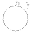
- the disks 101 and 102 have a first portion P1 having a first magnetic permeability and a second portion P2 having a second magnetic permeability higher than the first magnetic permeability, respectively.
- the first portion P1 of the disk 101 and the first portion P1 of the disk 102 are the same number, and are provided at positions where the disk 101 and the disk 102 overlap each other when viewed in the opposite direction (rotation axis direction of the rotor 120). ing.
- FIG. 3A is a plan view showing the plan shape of the disks 101 and 102 shown in FIG.
- the coil 104 can form a magnetic path FP (described later) that passes through the disks 101, 102, pillar 103, and rotor 120 by being energized. It is preferable that the coil 104 can apply a magnetic field having a magnetic flux density larger than the coercive force of the permanent magnet PM.
- the stator 100 further has a sensor 107 for detecting the magnetic flux of the magnetic path FP as a part of the magnetic path FP.
- the actuator 10 may further include a control unit 300 (described later) to control the voltage supplied to the coil 104 based on the magnetic flux FP detected by the sensor 107.
- the sensor 107 for example, a GMR (giant magnetoresistive effect) element, a Hall element, or the like can be used.
- the stator 100 has a structure in which a plurality of units 110 each having a disk 101, 102, a pillar 103, and a coil 104 are laminated. Specifically, in the present embodiment, a structure in which three units 110a to 110c are sequentially laminated is illustrated.
- the number of the plurality of units 110 is preferably 3 or more. According to this configuration, as will be described later, the rotor 120 can smoothly rotate along the outer edge of the stator 100. As shown in FIG. 2, it is preferable that the plurality of units 110 are integrally held by, for example, a screw S penetrating each central portion in the stacking direction.
- the shapes and dimensions of the three units 110a to 110c can be substantially the same.
- the shape of the outer peripheral surface of each unit U is substantially the same. More specifically, on the outer peripheral surface of each unit 110, more specifically, on each outer peripheral surface of the disks 101 and 102 of each unit 110, substantially the same number of first external teeth 105 having substantially the same shape are arranged. obtain. Further, when viewed along the stacking direction (rotation axis direction of the rotor 120) of the plurality of units 110a to 110c, the first external tooth 105A of the unit 110a, the first external tooth 105B of the unit 110b, and the first unit 110c are viewed. The external teeth 105C are combined so as not to overlap each other (different positions). For example, as shown in FIG.
- FIG. 3B is a plan view showing the plan shapes of the disks 101 and 102 in the units 110a to 110c shown in FIG.
- the coil 104 shapes and dimensions of the units 110a to 110c can be substantially the same. Further, the shapes and dimensions of the permanent magnets PM included in each of the units 110a to 110c can be substantially the same.
- FIG. 4 is a partially cutaway perspective view showing a part of the internal configuration of the actuator 10.
- the coils 104 of the units 110a to 110c are energized from the power supply unit 400 arranged outside the actuator 10 via a power cable or the like.
- the control unit 300 arranged inside the actuator 10 controls the supply of electric power to the coils 104 of the units 110a to 110c.
- the power supply unit 400 and the control unit 300 allow the coil 104 in each of the units 110a to 110c to form a magnetic path FP that passes through the disks 101, 102, the pillar 103, and the rotor 120.
- the direction of the current with respect to the individual coils 104 is switched in the opposite direction, the direction of the magnetic flux flowing through the magnetic path also becomes the opposite direction, and the directions of the magnetic poles of the units 110a to 110c may be opposite.
- control unit 300 may be configured to include, for example, a processing circuit such as a CPU (Central Processing Unit) or a GPU (Graphics Processing Unit).
- the control unit 300 can collectively control the operation of the actuator 10.
- the control unit 300 is not limited to the example in which it is arranged inside the actuator 10, and may be arranged outside the actuator 10.
- the power supply unit 400 is not limited to the example of being arranged outside the actuator 10, and may be arranged inside the actuator 10.
- the control unit 300 sequentially energizes each coil 104 in the plurality of units 110a to 110c to form a magnetic path FP in the plurality of units 110a to 110c.
- the rotor 120 is provided so as to be movable along the outer edges of the discs 101 and 102 while being in contact with the outer edges of the discs 101 and 102. Specifically, while rotating around the rotation axis 120J extending in the direction in which the disk 101 and the disk 102 face each other, that is, in the stacking direction of the plurality of units 110a to 110c, along the outer edges of the disks 101 and 102. It is designed to revolve.
- the rotor 120 includes, for example, second external teeth 121 (121A to 121E) that mesh with the first external teeth 105, and the second external teeth 121 are the first of the discs 101 and 102. It rotates and revolves while meshing with the external teeth 105.
- the rotor 120 has the same shape along the rotation shaft 120J, and is in contact with the outer edges of the discs 101 and 102 of the plurality of units 110a to 110c, respectively.
- the timing at which the second external tooth 121 meshes with the first external tooth 105A the timing at which the second external tooth 121 meshes with the first external tooth 105B, and the timing at which the second external tooth 121 meshes with the first external tooth 105C. It's different from the timing. That is, the second external teeth 121 do not mesh with the first external teeth 105A to 105C at the same time.
- the rotor 120 has a third magnetic permeability higher than the first magnetic permeability of the first portion P1 at the outer edges of the disks 101 and 102.
- the third magnetic permeability of the rotor 120 may be the same as the second magnetic permeability of the second portion P2 (that is, the first external tooth 105) of the disks 101 and 102.
- the planetary gear 130 rotates around the central axis of the stator 100 while meshing with the sun gear 140 as the rotor 120 rotates. Further, the number of external teeth 1300 of the planetary gear 130 and the number of second external teeth 121 of the rotor 120 may be designed to be the same.
- the number of the first external teeth 105 arranged on the outer peripheral surface of the stator 100 may be designed to be a predetermined number less than the number of teeth 1400 on the outer peripheral surface of the sun gear 140.
- the number of first external teeth 105 of the stator 100 can be N
- the number of teeth of the sun gear 140 can be N + 1.
- the sun gear 140 As shown in FIG. 1, the sun gear 140 is arranged inside the planetary gear 130 with respect to the central axis of the stator 100. Further, the sun gear 140 rotates while the teeth 1400 on the outer peripheral surface of the sun gear 140 mesh with the external teeth 1300 of the planetary gear 130.
- the rotation axis of the sun gear 140 is coaxial with, for example, the central axis of the stator 100.
- the sun gear 140 can be rotatably supported around the central axis of the stator 100.
- the bearing 142 is arranged between the housing 200 and the sun gear 140.
- the bearing 142 rotatably supports the sun gear 140 around the central axis of the stator 100.
- sun gear 140 can be connected to the output shaft (not shown) of the actuator 10.
- the present invention is not limited to this, and the sun gear 140 may be the output shaft of the actuator 10.
- Carrier 150 The carrier 150 is a ring type. The carrier 150 is fixed between the rotor 120 and the planetary gear 130.
- the carrier 150 can be rotatably supported around the central axis of the stator 100.
- the bearing 152 is arranged between the housing 200 and the carrier 150.
- the bearing 152 rotatably supports the carrier 150 around the central axis of the stator 100.
- FIG. 2 shows an example in which one carrier 150 is arranged on each end side of the stator 100 in the axial direction, but the present embodiment is not limited to such an example.
- only one carrier 150 may be arranged only on one end side (sun gear 140 side) of the stator 100 in the axial direction.
- a stator 100, a rotor 120, a sun gear 140, a bearing 142, a bearing 152, and the like may be arranged in the housing 200. Further, the housing 200 may support the stator 100, the bearing 142, the bearing 152, and the like.
- the shape of the housing 200 is not particularly limited.
- the housing 200 may have a cylindrical shape or a prismatic shape (such as a square pillar).
- FIG. 5 is a partially enlarged perspective view of the actuator 10 for explaining the outline of the operation of the actuator 10.
- the planetary gear 130 coaxially connected to the central axis of the rotor 120 starts to rotate around the central axis of the stator 100 (together with the rotor 120) while meshing with the sun gear 140.
- the sun gear 140 also begins to rotate around the central axis of the stator 100.
- the output torque can be increased according to the ratio (reduction ratio) between the number of first external teeth 105 of the stator 100 and the number of teeth of the sun gear 140.
- the carrier 150 can also rotate around the central axis of the stator 100 (together with the rotor 120).
- FIG. 7 is a schematic cross-sectional view for explaining the operating principle of the rotor 120. Specifically, FIG.
- the second external tooth 121 of the rotor 120 meshes with the first external tooth 105A of the unit 110a.
- the magnetic path FP is generated inside the unit 110b as shown in the leftmost figure of FIG. It is formed.
- the permanent magnet PM of the unit 110a is magnetized, the permanent magnet PM of the unit 110a is degaussed.
- a degaussing pulse larger than the coercive force of the permanent magnet PM of the unit 110a may be applied to the permanent magnet PM of the unit 110a.
- the rotor 120 receives a force so that the reactance of the magnetic path FP of the unit 110b approaches the minimum. That is, as shown in the leftmost figure of FIG. 6, the rotor 120 rotates the rotating shaft 120J so as to face the first external tooth 105B having a magnetic permeability higher than that of the gap 106B (FIG. 1) in the unit 110b. It moves while rotating as the center of rotation. This operation is referred to as Phase 1 for convenience.
- Phase 1 when the coil 104 of the unit 110b is energized to form the magnetic path FP, a magnetic field having a strength exceeding the coercive force is applied to the permanent magnet PM of the unit 110b, and the permanent magnet PM is magnetized. It is magnetized along the path FP. Therefore, the force that hinders (brakes) the rotational operation of the rotor 120 is sufficiently strengthened. In this way, the braking force with respect to the rotor 120 becomes stronger because the permanent magnet PM is magnetized to generate a force for attracting the rotor 120. Therefore, the rotor 120 tries to stay in the state of being meshed with the first external tooth 105B.
- the second external tooth 121 of the rotor 120 meshes with the first external tooth 105B of the unit 110b. It is in a state of being. In this state, the coil 104 of the unit 110b is turned off and only the coil 104 of the unit 110c is turned on under the control of the control unit 300. At that time, the permanent magnet PM of the unit 110b is degaussed. In that case, for example, a degaussing pulse larger than the coercive force of the permanent magnet PM of the unit 110b may be applied to the permanent magnet PM of the unit 110b.
- the magnetic path FP inside the unit 110b disappears, and the magnetic path FP is formed inside the unit 110c.
- the rotor 120 receives a force that causes the reactance of the magnetic path FP of the unit 110c to approach the minimum. That is, as shown in the central figure of FIG. 6, the rotor 120 rotates the rotation shaft 120J at the center of rotation so as to face the first external tooth 105C having a magnetic permeability higher than that of the gap 106C (FIG. 1) in the unit 110c. Move while rotating as. This operation is referred to as Phase 2 for convenience.
- the second external tooth 121 of the rotor 120 is outside the first outside of the unit 110c. It is in a state of meshing with the tooth 105C. In this state, based on the control of the control unit 300, the coil 104 of the unit 110c is turned off, and only the coil 104 of the unit 110a is turned on. At that time, the permanent magnet PM of the unit 110c is degaussed. At that time, the permanent magnet PM of the unit 110c is degaussed.
- a degaussing pulse larger than the coercive force of the permanent magnet PM of the unit 110c may be applied to the permanent magnet PM of the unit 110c.
- the magnetic path FP inside the unit 110c disappears, and the magnetic path FP is formed inside the unit 110a.
- the rotor 120 receives a force that causes the reactance of the magnetic path FP of the unit 110a to approach the minimum. That is, as shown in the rightmost figure of FIG. 6, the rotor 120 rotates the rotating shaft 120J so as to face the first external tooth 105A having a magnetic permeability higher than that of the gap 106A (FIG. 1) in the unit 110a. It moves while rotating as the center of rotation. This operation is referred to as Phase 3 for convenience.
- the rotation of the rotor 120 can be continued by sequentially repeating the above phases 1 to 3.
- Phase 1 Phase 2 or Phase 3 is completed, none of the coils 104 is energized, and a degaussing pulse larger than the coercive force of each permanent magnet PM is applied to all the permanent magnets PM.
- a degaussing pulse larger than the coercive force of each permanent magnet PM is applied to all the permanent magnets PM.
- the rotor 120 and the sun gear 140 can be freely rotated by applying an external force with almost no resistance.
- the frictional resistance between each gear and the inertial resistance of each gear are unavoidable. Further, their frictional resistance and inertial resistance are amplified by the gear ratios of the stator 100, the planetary gear 130 and the sun gear 140.
- the actuator 10 can be used as a brake.
- the three devices of the motor, the gear, and the brake can be used as an integrated device. For this reason, the ratio of the output torque to the total weight can be improved because the parts are shared as compared with the case where three independent components such as a motor, a gear, and a brake are put together.
- the coil 104 since the coil 104 has a structure that only needs to act for an extremely short time in order to magnetize the permanent magnet PM, it is possible to reduce the power consumption especially at the time of low speed operation.
- the magnetization and degaussing of the permanent magnet PM can be set by the on / off operation of the coil 104, the rotational operation of the rotor 120 and the sun gear 140 and the braking operation of the rotor 120 and the sun gear 140 can be easily realized. Is.
- Modification example 1 In one embodiment described above, an example is shown in which the carrier 150 supports the rotor 120, but the present disclosure is not limited to such an example.
- the ring gear 160 arranged on the opposite side of the stator 100 with respect to the rotor 120 may hold the rotor 120 rotatably.
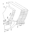
- FIG. 9 is a diagram showing an example of the appearance configuration of the actuator 10B according to the modified example 2.
- the individual rotors 120 have teeth arranged on the outer peripheral surface of the rotor 120 meshing with the first outer teeth 105 arranged on the outer peripheral surface of the stator 100. , Can rotate around the central axis of the stator 100, respectively. Further, each of the plurality of rotors 120 may be arranged at substantially equal intervals with respect to each other in the circumferential direction of the outer peripheral surface of the stator 100.
- the actuator 10B of the second modification includes, for example, a large number of rotors 120 and a large number of planetary gears 130, as shown in FIG.
- a large number of planetary gears 130 rotate while meshing with the sun gear 140
- an existing strain wave gearing gear reducer only two teeth mesh with the external gear on the input shaft side (more specifically, the flexspline) and the internal gear on the output shaft side (more specifically, the circular spline). Rotate while.
- the actuator 10B according to the second modification since each of the large number of planetary gears 130 and the sun gear 140 rotate while simultaneously meshing with each other, each gear is less likely to break than the existing strain wave gearing reducer.
- the actuator 10B according to the second modification can include a larger number of planetary gears 130 than the number of planetary gears in the existing planetary gear reducer. Therefore, each gear is less likely to break than the existing planetary gear reducer.
- the external tooth gear on which the first external tooth 105 is formed is used as the discs 101 and 102, but the present disclosure is not limited to this.
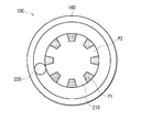
- a disc-shaped member can be used like the disk 210 in the actuator 10C as the modification 3 shown in FIG.
- a first portion P1 having a first magnetic permeability and a second portion P2 having a second magnetic permeability higher than the first magnetic permeability are alternately arranged on the outer edge thereof.
- the disc 210 has a smooth outer peripheral surface.
- the second portion P2 is made of a high magnetic permeability material such as soft ferrite.
- a non-magnetic material such as resin or aluminum can be used.
- a substantially cylindrical rotor 220 having a smooth outer peripheral surface can be used instead of the rotor 120 which is an external gear.
- the actuator of the present disclosure has the following industrial applicability.
- the actuator of the present disclosure can be applied to, for example, the robot arm 1001 shown in FIG. FIG. 11 is a schematic view showing an example of the overall configuration of the robot arm 1001.
- the robot arm 1001 has a structure in which a base end portion 1002, an intermediate portion 1003, an intermediate portion 1004, and a tip end portion 1005 are connected in order.
- the structure in which the base end portion 1002, the intermediate portion 1003, the intermediate portion 1004, and the tip end portion 1005 are connected in this order is referred to as an arm unit.
- the robot arm 1001 further includes, for example, a control unit 1007 and a power supply 1008.
- the base end portion 1002 has, for example, a base portion 1002A fixed to a floor surface or the like, a rotating portion 1002B, and a joint portion 1002D.
- the actuator 10 of the present disclosure may be arranged in the joint portion 1002D.
- the rotating portion 1002B is a member having a substantially columnar shape, and is provided so as to be rotatable with respect to the base portion 1002A in the rotation direction R1002 indicated by an arrow.
- the joint portion 1002D is fixed to the rotating portion 1002B and can rotate integrally with the rotating portion 1002B in the rotation direction R1002.
- An arm portion 1003A is attached to the joint portion 1002D.
- the arm portion 1003A is rotatably provided in the rotation direction R1003 indicated by the arrow with the joint portion 1002D as the center of rotation by the actuator 10 provided in the joint portion 1002D.
- the intermediate portion 1003 has a joint portion 1003B in addition to the arm portion 1003A.
- the intermediate portion 1004 has an arm portion 1004A and a joint portion 1004B.
- the actuator 10 of the present disclosure can also be arranged in the joint portion 1003B and the joint portion 1004B.
- the tip portion 1005 includes a main body 1005A and a manipulator 1005B.
- the robot arm 1001 can drive the actuators 10 built in the joints 1002D, 1003B and 1004B based on the control of the control unit 1007. According to the robot arm 1001, although it has a compact and lightweight configuration, it is possible to obtain a high output torque particularly at low speed operation, which is advantageous for weight reduction and cost reduction. Further, in the robot arm 1001, the actuator 10 can be used as a braking device by controlling the on / off of the coil 104. Therefore, since the robot arm 1001 has high safety, it is suitable for use as a device for performing various operations in a public environment. For example, it may be applied to assistance such as transportation work at a store, indoor and outdoor farming work, medical practice, transportation work, cargo handling work, or visual inspection work of products indoors and outdoors.
- the pillar 103 is configured by the laminated structure of the sensor 107 and the permanent magnet PM is illustrated, but the present disclosure is not limited to this. ..
- all of the pillar 103 may be composed of the permanent magnet PM, or the pillar 103 may include other components in addition to the permanent magnet PM and the sensor 107.
- the magnetic recording medium as one embodiment of the present disclosure, good electromagnetic conversion characteristics can be maintained even after the total thickness is reduced and repeated recording or repeated reproduction is performed.
- the effect of the present disclosure is not limited to this, and any effect described in the present specification may be used.
- the present technology can have the following configurations. (1) A disk, a pillar containing a permanent magnet, and a stator having a coil wound around the pillar. It is provided with a rotor provided so as to be movable along the outer edge of the disk while being in contact with the outer edge of the disk. The coil can form a magnetic path through the disk, the pillar, and the rotor when energized.
- a first portion having a first magnetic permeability and a second portion having a second magnetic permeability higher than the first magnetic permeability are alternately arranged along the outer edge of the disc.
- Actuator. (2) The actuator according to (1) above, wherein the stator further has a sensor for detecting the magnetic flux of the magnetic path in a part of the magnetic path. (3) The actuator according to (1) above, further comprising a control unit that controls a voltage supplied to the coil based on the magnetic flux detected by the sensor. (4) The actuator according to any one of (1) to (3) above, wherein the stator has a structure in which a plurality of units having the disc, the pillar, and the coil are laminated.
- the actuator according to (4) above further comprising a control unit that forms the magnetic path in the plurality of units and magnetizes the permanent magnet by sequentially energizing each of the coils in the plurality of units.
- the control unit degausses the permanent magnet magnetized immediately before when each of the coils in the plurality of units is sequentially energized.
- the rotor is in contact with the outer edge of the disk of each of the plurality of units.
- the second portion of each of the disks in the plurality of units is located at different positions when viewed along the stacking direction of the plurality of units according to any one of (4) to (7) above.
- the disc comprises a first external tooth as the first portion and a gap as the second portion.
- the coil can apply a magnetic field having a magnetic flux density larger than the coercive force of the permanent magnet.
- the rotor has a third magnetic permeability higher than that of the first magnetic permeability.
- the disc includes a first disc and a second disc.
Landscapes
- Engineering & Computer Science (AREA)
- Power Engineering (AREA)
- General Engineering & Computer Science (AREA)
- Microelectronics & Electronic Packaging (AREA)
- Mechanical Engineering (AREA)
- Connection Of Motors, Electrical Generators, Mechanical Devices, And The Like (AREA)
Priority Applications (3)
| Application Number | Priority Date | Filing Date | Title |
|---|---|---|---|
| US17/639,663 US20220294311A1 (en) | 2019-09-11 | 2020-08-28 | Actuator |
| JP2021545216A JPWO2021049327A1 (https=) | 2019-09-11 | 2020-08-28 | |
| CN202080062585.3A CN114342231A (zh) | 2019-09-11 | 2020-08-28 | 执行器 |
Applications Claiming Priority (2)
| Application Number | Priority Date | Filing Date | Title |
|---|---|---|---|
| JP2019165309 | 2019-09-11 | ||
| JP2019-165309 | 2019-09-11 |
Publications (1)
| Publication Number | Publication Date |
|---|---|
| WO2021049327A1 true WO2021049327A1 (ja) | 2021-03-18 |
Family
ID=74867229
Family Applications (1)
| Application Number | Title | Priority Date | Filing Date |
|---|---|---|---|
| PCT/JP2020/032654 Ceased WO2021049327A1 (ja) | 2019-09-11 | 2020-08-28 | アクチュエータ |
Country Status (4)
| Country | Link |
|---|---|
| US (1) | US20220294311A1 (https=) |
| JP (1) | JPWO2021049327A1 (https=) |
| CN (1) | CN114342231A (https=) |
| WO (1) | WO2021049327A1 (https=) |
Citations (2)
| Publication number | Priority date | Publication date | Assignee | Title |
|---|---|---|---|---|
| JPS63156573U (https=) * | 1987-03-30 | 1988-10-13 | ||
| JP2006115567A (ja) * | 2004-10-12 | 2006-04-27 | Toyota Motor Corp | 駆動装置 |
Family Cites Families (3)
| Publication number | Priority date | Publication date | Assignee | Title |
|---|---|---|---|---|
| US8378543B2 (en) * | 2009-11-02 | 2013-02-19 | Calnetix Technologies, L.L.C. | Generating electromagnetic forces in large air gaps |
| US8405479B1 (en) * | 2009-12-22 | 2013-03-26 | The Boeing Company | Three-dimensional magnet structure and associated method |
| WO2017109818A1 (en) * | 2015-12-22 | 2017-06-29 | Sony Mobile Communications Inc. | Vibrator assemblies and electronic devices incorporating same |
-
2020
- 2020-08-28 JP JP2021545216A patent/JPWO2021049327A1/ja active Pending
- 2020-08-28 US US17/639,663 patent/US20220294311A1/en not_active Abandoned
- 2020-08-28 WO PCT/JP2020/032654 patent/WO2021049327A1/ja not_active Ceased
- 2020-08-28 CN CN202080062585.3A patent/CN114342231A/zh not_active Withdrawn
Patent Citations (2)
| Publication number | Priority date | Publication date | Assignee | Title |
|---|---|---|---|---|
| JPS63156573U (https=) * | 1987-03-30 | 1988-10-13 | ||
| JP2006115567A (ja) * | 2004-10-12 | 2006-04-27 | Toyota Motor Corp | 駆動装置 |
Also Published As
| Publication number | Publication date |
|---|---|
| US20220294311A1 (en) | 2022-09-15 |
| JPWO2021049327A1 (https=) | 2021-03-18 |
| CN114342231A (zh) | 2022-04-12 |
Similar Documents
| Publication | Publication Date | Title |
|---|---|---|
| US8674576B2 (en) | Electropermanent magnet-based motors | |
| US5481147A (en) | Synchronous inductor electric motor | |
| US7999427B2 (en) | Directed flux motor | |
| JP2007525937A5 (https=) | ||
| TWI413347B (zh) | 具斷電自鎖功能之磁控式機器臂關節致動器 | |
| CN108494202B (zh) | 一种可磁化重构的机器人关节电机 | |
| JP5513739B2 (ja) | 電動機 | |
| WO2021049327A1 (ja) | アクチュエータ | |
| JP2013223417A (ja) | 固定式永久磁石発電機 | |
| JP2010161878A (ja) | コア付筒状リニアモータの台形型マグネットスキュー構造 | |
| JP3106144B2 (ja) | 複合磁性体の起電力発生装置 | |
| JPH07312885A (ja) | 超電導アクチュエータ | |
| JP2007067252A (ja) | ハイブリッド型磁石並びにそれを用いた電動モータ及び発電機 | |
| JPH10225098A (ja) | 発電機および電動機 | |
| JPH03195343A (ja) | ステッピングモータの着磁器 | |
| CN102371589B (zh) | 具有断电自锁功能的磁控式机器臂关节制动器 | |
| JP2008281078A (ja) | 動力伝達装置 | |
| JP5540482B2 (ja) | アクチュエータ | |
| JP2007215583A (ja) | 磁界制御方法および磁界発生装置 | |
| TWI652883B (zh) | Magnetic power generator | |
| CN1736015A (zh) | 平转动电发生器 | |
| JP3897043B2 (ja) | 磁力回転装置 | |
| WO2022210823A1 (ja) | 多自由度モータ | |
| JP6774669B1 (ja) | 発電機 | |
| JPH08320386A (ja) | 多極モータとそれを用いた時計機械体 |
Legal Events
| Date | Code | Title | Description |
|---|---|---|---|
| 121 | Ep: the epo has been informed by wipo that ep was designated in this application |
Ref document number: 20862435 Country of ref document: EP Kind code of ref document: A1 |
|
| ENP | Entry into the national phase |
Ref document number: 2021545216 Country of ref document: JP Kind code of ref document: A |
|
| NENP | Non-entry into the national phase |
Ref country code: DE |
|
| 122 | Ep: pct application non-entry in european phase |
Ref document number: 20862435 Country of ref document: EP Kind code of ref document: A1 |