WO2021049108A1 - 車両制御装置、車両制御方法、車両運動制御システム、及びレーン推定装置 - Google Patents
車両制御装置、車両制御方法、車両運動制御システム、及びレーン推定装置 Download PDFInfo
- Publication number
- WO2021049108A1 WO2021049108A1 PCT/JP2020/022156 JP2020022156W WO2021049108A1 WO 2021049108 A1 WO2021049108 A1 WO 2021049108A1 JP 2020022156 W JP2020022156 W JP 2020022156W WO 2021049108 A1 WO2021049108 A1 WO 2021049108A1
- Authority
- WO
- WIPO (PCT)
- Prior art keywords
- information
- vehicle
- lane
- acquired
- curvature
- Prior art date
Links
- 238000000034 method Methods 0.000 title claims abstract description 73
- 238000001514 detection method Methods 0.000 claims abstract description 21
- 238000004364 calculation method Methods 0.000 claims description 15
- 238000005070 sampling Methods 0.000 claims description 15
- 238000005192 partition Methods 0.000 abstract 3
- 238000000638 solvent extraction Methods 0.000 abstract 1
- 238000005259 measurement Methods 0.000 description 51
- 238000012937 correction Methods 0.000 description 36
- 230000006870 function Effects 0.000 description 30
- 238000011156 evaluation Methods 0.000 description 27
- 230000006399 behavior Effects 0.000 description 22
- 239000011159 matrix material Substances 0.000 description 21
- 238000012545 processing Methods 0.000 description 20
- 238000010586 diagram Methods 0.000 description 10
- 230000000694 effects Effects 0.000 description 8
- 230000002411 adverse Effects 0.000 description 5
- 239000013598 vector Substances 0.000 description 5
- 238000005452 bending Methods 0.000 description 3
- 238000004519 manufacturing process Methods 0.000 description 3
- 230000001133 acceleration Effects 0.000 description 2
- 230000007423 decrease Effects 0.000 description 2
- 238000009826 distribution Methods 0.000 description 2
- 238000005457 optimization Methods 0.000 description 2
- 230000003213 activating effect Effects 0.000 description 1
- 230000002238 attenuated effect Effects 0.000 description 1
- 238000012888 cubic function Methods 0.000 description 1
- 238000003384 imaging method Methods 0.000 description 1
- 239000004973 liquid crystal related substance Substances 0.000 description 1
- 239000003550 marker Substances 0.000 description 1
- 238000012986 modification Methods 0.000 description 1
- 230000004048 modification Effects 0.000 description 1
- 230000002265 prevention Effects 0.000 description 1
Images


Classifications
-
- B—PERFORMING OPERATIONS; TRANSPORTING
- B62—LAND VEHICLES FOR TRAVELLING OTHERWISE THAN ON RAILS
- B62D—MOTOR VEHICLES; TRAILERS
- B62D15/00—Steering not otherwise provided for
- B62D15/02—Steering position indicators ; Steering position determination; Steering aids
- B62D15/025—Active steering aids, e.g. helping the driver by actively influencing the steering system after environment evaluation
-
- B—PERFORMING OPERATIONS; TRANSPORTING
- B60—VEHICLES IN GENERAL
- B60W—CONJOINT CONTROL OF VEHICLE SUB-UNITS OF DIFFERENT TYPE OR DIFFERENT FUNCTION; CONTROL SYSTEMS SPECIALLY ADAPTED FOR HYBRID VEHICLES; ROAD VEHICLE DRIVE CONTROL SYSTEMS FOR PURPOSES NOT RELATED TO THE CONTROL OF A PARTICULAR SUB-UNIT
- B60W10/00—Conjoint control of vehicle sub-units of different type or different function
- B60W10/20—Conjoint control of vehicle sub-units of different type or different function including control of steering systems
-
- B—PERFORMING OPERATIONS; TRANSPORTING
- B60—VEHICLES IN GENERAL
- B60W—CONJOINT CONTROL OF VEHICLE SUB-UNITS OF DIFFERENT TYPE OR DIFFERENT FUNCTION; CONTROL SYSTEMS SPECIALLY ADAPTED FOR HYBRID VEHICLES; ROAD VEHICLE DRIVE CONTROL SYSTEMS FOR PURPOSES NOT RELATED TO THE CONTROL OF A PARTICULAR SUB-UNIT
- B60W30/00—Purposes of road vehicle drive control systems not related to the control of a particular sub-unit, e.g. of systems using conjoint control of vehicle sub-units
- B60W30/10—Path keeping
- B60W30/12—Lane keeping
-
- B—PERFORMING OPERATIONS; TRANSPORTING
- B60—VEHICLES IN GENERAL
- B60W—CONJOINT CONTROL OF VEHICLE SUB-UNITS OF DIFFERENT TYPE OR DIFFERENT FUNCTION; CONTROL SYSTEMS SPECIALLY ADAPTED FOR HYBRID VEHICLES; ROAD VEHICLE DRIVE CONTROL SYSTEMS FOR PURPOSES NOT RELATED TO THE CONTROL OF A PARTICULAR SUB-UNIT
- B60W40/00—Estimation or calculation of non-directly measurable driving parameters for road vehicle drive control systems not related to the control of a particular sub unit, e.g. by using mathematical models
- B60W40/02—Estimation or calculation of non-directly measurable driving parameters for road vehicle drive control systems not related to the control of a particular sub unit, e.g. by using mathematical models related to ambient conditions
- B60W40/06—Road conditions
- B60W40/072—Curvature of the road
-
- B—PERFORMING OPERATIONS; TRANSPORTING
- B60—VEHICLES IN GENERAL
- B60W—CONJOINT CONTROL OF VEHICLE SUB-UNITS OF DIFFERENT TYPE OR DIFFERENT FUNCTION; CONTROL SYSTEMS SPECIALLY ADAPTED FOR HYBRID VEHICLES; ROAD VEHICLE DRIVE CONTROL SYSTEMS FOR PURPOSES NOT RELATED TO THE CONTROL OF A PARTICULAR SUB-UNIT
- B60W40/00—Estimation or calculation of non-directly measurable driving parameters for road vehicle drive control systems not related to the control of a particular sub unit, e.g. by using mathematical models
- B60W40/10—Estimation or calculation of non-directly measurable driving parameters for road vehicle drive control systems not related to the control of a particular sub unit, e.g. by using mathematical models related to vehicle motion
- B60W40/105—Speed
-
- B—PERFORMING OPERATIONS; TRANSPORTING
- B60—VEHICLES IN GENERAL
- B60W—CONJOINT CONTROL OF VEHICLE SUB-UNITS OF DIFFERENT TYPE OR DIFFERENT FUNCTION; CONTROL SYSTEMS SPECIALLY ADAPTED FOR HYBRID VEHICLES; ROAD VEHICLE DRIVE CONTROL SYSTEMS FOR PURPOSES NOT RELATED TO THE CONTROL OF A PARTICULAR SUB-UNIT
- B60W50/00—Details of control systems for road vehicle drive control not related to the control of a particular sub-unit, e.g. process diagnostic or vehicle driver interfaces
- B60W50/08—Interaction between the driver and the control system
- B60W50/14—Means for informing the driver, warning the driver or prompting a driver intervention
- B60W50/16—Tactile feedback to the driver, e.g. vibration or force feedback to the driver on the steering wheel or the accelerator pedal
-
- B—PERFORMING OPERATIONS; TRANSPORTING
- B62—LAND VEHICLES FOR TRAVELLING OTHERWISE THAN ON RAILS
- B62D—MOTOR VEHICLES; TRAILERS
- B62D6/00—Arrangements for automatically controlling steering depending on driving conditions sensed and responded to, e.g. control circuits
-
- G—PHYSICS
- G01—MEASURING; TESTING
- G01C—MEASURING DISTANCES, LEVELS OR BEARINGS; SURVEYING; NAVIGATION; GYROSCOPIC INSTRUMENTS; PHOTOGRAMMETRY OR VIDEOGRAMMETRY
- G01C21/00—Navigation; Navigational instruments not provided for in groups G01C1/00 - G01C19/00
- G01C21/26—Navigation; Navigational instruments not provided for in groups G01C1/00 - G01C19/00 specially adapted for navigation in a road network
-
- G—PHYSICS
- G06—COMPUTING; CALCULATING OR COUNTING
- G06V—IMAGE OR VIDEO RECOGNITION OR UNDERSTANDING
- G06V10/00—Arrangements for image or video recognition or understanding
- G06V10/98—Detection or correction of errors, e.g. by rescanning the pattern or by human intervention; Evaluation of the quality of the acquired patterns
- G06V10/993—Evaluation of the quality of the acquired pattern
-
- G—PHYSICS
- G06—COMPUTING; CALCULATING OR COUNTING
- G06V—IMAGE OR VIDEO RECOGNITION OR UNDERSTANDING
- G06V20/00—Scenes; Scene-specific elements
- G06V20/50—Context or environment of the image
- G06V20/56—Context or environment of the image exterior to a vehicle by using sensors mounted on the vehicle
- G06V20/58—Recognition of moving objects or obstacles, e.g. vehicles or pedestrians; Recognition of traffic objects, e.g. traffic signs, traffic lights or roads
-
- G—PHYSICS
- G06—COMPUTING; CALCULATING OR COUNTING
- G06V—IMAGE OR VIDEO RECOGNITION OR UNDERSTANDING
- G06V20/00—Scenes; Scene-specific elements
- G06V20/50—Context or environment of the image
- G06V20/56—Context or environment of the image exterior to a vehicle by using sensors mounted on the vehicle
- G06V20/588—Recognition of the road, e.g. of lane markings; Recognition of the vehicle driving pattern in relation to the road
-
- G—PHYSICS
- G08—SIGNALLING
- G08G—TRAFFIC CONTROL SYSTEMS
- G08G1/00—Traffic control systems for road vehicles
- G08G1/16—Anti-collision systems
-
- G—PHYSICS
- G08—SIGNALLING
- G08G—TRAFFIC CONTROL SYSTEMS
- G08G1/00—Traffic control systems for road vehicles
- G08G1/16—Anti-collision systems
- G08G1/167—Driving aids for lane monitoring, lane changing, e.g. blind spot detection
-
- B—PERFORMING OPERATIONS; TRANSPORTING
- B60—VEHICLES IN GENERAL
- B60W—CONJOINT CONTROL OF VEHICLE SUB-UNITS OF DIFFERENT TYPE OR DIFFERENT FUNCTION; CONTROL SYSTEMS SPECIALLY ADAPTED FOR HYBRID VEHICLES; ROAD VEHICLE DRIVE CONTROL SYSTEMS FOR PURPOSES NOT RELATED TO THE CONTROL OF A PARTICULAR SUB-UNIT
- B60W2420/00—Indexing codes relating to the type of sensors based on the principle of their operation
- B60W2420/40—Photo, light or radio wave sensitive means, e.g. infrared sensors
- B60W2420/403—Image sensing, e.g. optical camera
-
- B—PERFORMING OPERATIONS; TRANSPORTING
- B60—VEHICLES IN GENERAL
- B60W—CONJOINT CONTROL OF VEHICLE SUB-UNITS OF DIFFERENT TYPE OR DIFFERENT FUNCTION; CONTROL SYSTEMS SPECIALLY ADAPTED FOR HYBRID VEHICLES; ROAD VEHICLE DRIVE CONTROL SYSTEMS FOR PURPOSES NOT RELATED TO THE CONTROL OF A PARTICULAR SUB-UNIT
- B60W2520/00—Input parameters relating to overall vehicle dynamics
- B60W2520/10—Longitudinal speed
-
- B—PERFORMING OPERATIONS; TRANSPORTING
- B60—VEHICLES IN GENERAL
- B60W—CONJOINT CONTROL OF VEHICLE SUB-UNITS OF DIFFERENT TYPE OR DIFFERENT FUNCTION; CONTROL SYSTEMS SPECIALLY ADAPTED FOR HYBRID VEHICLES; ROAD VEHICLE DRIVE CONTROL SYSTEMS FOR PURPOSES NOT RELATED TO THE CONTROL OF A PARTICULAR SUB-UNIT
- B60W2520/00—Input parameters relating to overall vehicle dynamics
- B60W2520/12—Lateral speed
- B60W2520/125—Lateral acceleration
-
- B—PERFORMING OPERATIONS; TRANSPORTING
- B60—VEHICLES IN GENERAL
- B60W—CONJOINT CONTROL OF VEHICLE SUB-UNITS OF DIFFERENT TYPE OR DIFFERENT FUNCTION; CONTROL SYSTEMS SPECIALLY ADAPTED FOR HYBRID VEHICLES; ROAD VEHICLE DRIVE CONTROL SYSTEMS FOR PURPOSES NOT RELATED TO THE CONTROL OF A PARTICULAR SUB-UNIT
- B60W2520/00—Input parameters relating to overall vehicle dynamics
- B60W2520/14—Yaw
-
- B—PERFORMING OPERATIONS; TRANSPORTING
- B60—VEHICLES IN GENERAL
- B60W—CONJOINT CONTROL OF VEHICLE SUB-UNITS OF DIFFERENT TYPE OR DIFFERENT FUNCTION; CONTROL SYSTEMS SPECIALLY ADAPTED FOR HYBRID VEHICLES; ROAD VEHICLE DRIVE CONTROL SYSTEMS FOR PURPOSES NOT RELATED TO THE CONTROL OF A PARTICULAR SUB-UNIT
- B60W2540/00—Input parameters relating to occupants
- B60W2540/18—Steering angle
-
- B—PERFORMING OPERATIONS; TRANSPORTING
- B60—VEHICLES IN GENERAL
- B60W—CONJOINT CONTROL OF VEHICLE SUB-UNITS OF DIFFERENT TYPE OR DIFFERENT FUNCTION; CONTROL SYSTEMS SPECIALLY ADAPTED FOR HYBRID VEHICLES; ROAD VEHICLE DRIVE CONTROL SYSTEMS FOR PURPOSES NOT RELATED TO THE CONTROL OF A PARTICULAR SUB-UNIT
- B60W2552/00—Input parameters relating to infrastructure
- B60W2552/30—Road curve radius
-
- B—PERFORMING OPERATIONS; TRANSPORTING
- B60—VEHICLES IN GENERAL
- B60W—CONJOINT CONTROL OF VEHICLE SUB-UNITS OF DIFFERENT TYPE OR DIFFERENT FUNCTION; CONTROL SYSTEMS SPECIALLY ADAPTED FOR HYBRID VEHICLES; ROAD VEHICLE DRIVE CONTROL SYSTEMS FOR PURPOSES NOT RELATED TO THE CONTROL OF A PARTICULAR SUB-UNIT
- B60W2552/00—Input parameters relating to infrastructure
- B60W2552/53—Road markings, e.g. lane marker or crosswalk
-
- B—PERFORMING OPERATIONS; TRANSPORTING
- B60—VEHICLES IN GENERAL
- B60W—CONJOINT CONTROL OF VEHICLE SUB-UNITS OF DIFFERENT TYPE OR DIFFERENT FUNCTION; CONTROL SYSTEMS SPECIALLY ADAPTED FOR HYBRID VEHICLES; ROAD VEHICLE DRIVE CONTROL SYSTEMS FOR PURPOSES NOT RELATED TO THE CONTROL OF A PARTICULAR SUB-UNIT
- B60W2554/00—Input parameters relating to objects
- B60W2554/80—Spatial relation or speed relative to objects
- B60W2554/802—Longitudinal distance
-
- B—PERFORMING OPERATIONS; TRANSPORTING
- B60—VEHICLES IN GENERAL
- B60W—CONJOINT CONTROL OF VEHICLE SUB-UNITS OF DIFFERENT TYPE OR DIFFERENT FUNCTION; CONTROL SYSTEMS SPECIALLY ADAPTED FOR HYBRID VEHICLES; ROAD VEHICLE DRIVE CONTROL SYSTEMS FOR PURPOSES NOT RELATED TO THE CONTROL OF A PARTICULAR SUB-UNIT
- B60W2556/00—Input parameters relating to data
- B60W2556/20—Data confidence level
-
- B—PERFORMING OPERATIONS; TRANSPORTING
- B60—VEHICLES IN GENERAL
- B60W—CONJOINT CONTROL OF VEHICLE SUB-UNITS OF DIFFERENT TYPE OR DIFFERENT FUNCTION; CONTROL SYSTEMS SPECIALLY ADAPTED FOR HYBRID VEHICLES; ROAD VEHICLE DRIVE CONTROL SYSTEMS FOR PURPOSES NOT RELATED TO THE CONTROL OF A PARTICULAR SUB-UNIT
- B60W2556/00—Input parameters relating to data
- B60W2556/25—Data precision
-
- B—PERFORMING OPERATIONS; TRANSPORTING
- B60—VEHICLES IN GENERAL
- B60W—CONJOINT CONTROL OF VEHICLE SUB-UNITS OF DIFFERENT TYPE OR DIFFERENT FUNCTION; CONTROL SYSTEMS SPECIALLY ADAPTED FOR HYBRID VEHICLES; ROAD VEHICLE DRIVE CONTROL SYSTEMS FOR PURPOSES NOT RELATED TO THE CONTROL OF A PARTICULAR SUB-UNIT
- B60W2556/00—Input parameters relating to data
- B60W2556/45—External transmission of data to or from the vehicle
- B60W2556/50—External transmission of data to or from the vehicle of positioning data, e.g. GPS [Global Positioning System] data
-
- B—PERFORMING OPERATIONS; TRANSPORTING
- B60—VEHICLES IN GENERAL
- B60W—CONJOINT CONTROL OF VEHICLE SUB-UNITS OF DIFFERENT TYPE OR DIFFERENT FUNCTION; CONTROL SYSTEMS SPECIALLY ADAPTED FOR HYBRID VEHICLES; ROAD VEHICLE DRIVE CONTROL SYSTEMS FOR PURPOSES NOT RELATED TO THE CONTROL OF A PARTICULAR SUB-UNIT
- B60W2710/00—Output or target parameters relating to a particular sub-units
- B60W2710/20—Steering systems
- B60W2710/202—Steering torque
Definitions
- the present invention relates to a vehicle control device, a vehicle control method, a vehicle motion control system, and a lane estimation device.
- the driving support device of Patent Document 1 includes an image acquisition unit that acquires an image taken by an in-vehicle camera, a lane marking recognition unit that recognizes a lane marking that divides the lane in which the own vehicle travels based on the captured image, and road information.
- the road information acquisition unit that acquires the information
- the reliability setting unit that sets the reliability of the lane markings recognized by the lane marking recognition unit based on the road information
- the driving support of the own vehicle based on the recognized lane markings It is provided with a driving support unit that executes the operation and makes the control contents in the driving support different according to the reliability.
- the present invention has been made in view of the conventional circumstances, and an object of the present invention is to provide a vehicle control device, a vehicle control method, a vehicle motion control system, and a lane estimation device, which can improve the recognition performance of a lane marking. To provide.
- the present invention in one aspect thereof, based on the outside world information acquired from the outside world recognition unit, the first information regarding the lane marking for dividing the lane in which the vehicle travels is acquired and acquired from the road shape information acquisition unit. Based on the information on the road shape, the second information on the curvature of the lane is acquired, and the third information on the behavior of the vehicle is acquired based on the physical quantity on the motion state of the vehicle acquired from the vehicle motion state detection unit. , The lane information including the information on the curvature of the lane marking and the information on the relative position of the vehicle with respect to the lane marking is estimated based on the first information, the second information, and the third information. To do.
- the recognition performance of the lane marking can be improved, and the performance of the lane keep control can be improved.
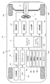
- FIG. 1 is a system block diagram showing one aspect of the vehicle motion control system 20 included in the vehicle (automobile) 10.
- the vehicle motion control system 20 includes an automatic driving mode in which the vehicle 10 performs steering control, in other words, lane keeping control, so that the vehicle 10 travels along the traveling lane without the driver operating the steering wheel 11. It has at least one of the driving support modes that notify the driver that the vehicle is about to deviate from the driving lane.
- the automatic driving mode can be a mode in which the vehicle speed is controlled in addition to the steering control described above.
- the vehicle motion control system 20 includes a control unit 21 as an aspect of the vehicle control device.
- the control unit 21 is an electronic control device mainly composed of a microcomputer 21a including a processor, a memory, an I / O, and a bus connecting these, and the microcomputer 21a as a control unit performs calculations based on input information. By outputting the control command as the calculation result, vehicle control including steering control is performed.
- the outside world recognition sensor 22 measures the front of the vehicle 10 (own vehicle) and draws a lane marking line (for example, a white line or a yellow line) on the road to divide the left and right of the lane in which the vehicle 10 is traveling. And an object existing in front of the vehicle 10, and further, the relative distance from the vehicle 10 to the lane marking and the relative distance from the vehicle 10 to the object are measured.
- a sensor such as a stereo camera or LiDAR (Light Detection and Ranging, Laser Imaging Detection and Ranging) that can measure both the shape of an object in front of the vehicle and the distance from the vehicle 10 to the object is used.
- the external world recognition sensor 22 can be configured by combining a plurality of sensors such as a monocular camera, a millimeter wave radar, and an ultrasonic sensor that can measure either the shape of an object in front of the vehicle or the distance to the object. ..
- the outside world recognition processing device 23 is based on the information of the lane markings detected by the outside world recognition sensor 22, the relative distance between the vehicle 10 and the left and right lane markings, the yaw angle of the vehicle 10, and the lane (in other words, the traveling route). Calculate the curvature of the lane marking corresponding to the curvature of. Further, the outside world recognition processing device 23 recognizes the preceding vehicle traveling in front of the vehicle 10 based on the information of the object existing in front of the vehicle 10 detected by the outside world recognition sensor 22, and the vehicle 10 and the preceding vehicle Calculate the relative distance.
- the outside world recognition sensor 22 and the outside world recognition processing device 23 constitute an outside world recognition unit that recognizes the outside world information of the vehicle 10. Further, the information on the relative distance between the vehicle 10 and the left and right lane markings, the yaw angle, and the curvature of the lane markings calculated by the outside world recognition processing device 23 is information on the lane markings, and in the present application, these outside world recognition sensors The information about the lane marking obtained by using 22 is referred to as the first information.
- the GPS (Global Positioning System) 24 measures the positional relationship between the vehicle 10 and a plurality of GPS satellites, and calculates the latitude and longitude indicating the current position of the vehicle 10 and the direction angle of the vehicle 10 based on the measurement results. ..
- the navigation system 25 attaches a liquid crystal display to a map screen in which a marker indicating the current position of the vehicle 10 is superimposed on a road map around the vehicle 10 based on the information and map information regarding the current position of the vehicle 10 acquired from the GPS 24. Display on.
- the navigation system 25 searches for the optimum guidance route from the current position to the destination specified by the driver, superimposes the guidance route on the map screen, displays branch information on the map screen, and speaks (in other words, in other words). For example, voice) is used to guide the driver to change course.
- the control unit 21 can acquire information on the shape of the road on which the vehicle 10 is traveling by using the navigation system 25, and the navigation system 25 is a road shape information acquisition unit that acquires information on the road shape. Corresponds to. Further, as will be described later, the control unit 21 calculates information on the curvature of the lane based on the information on the road shape acquired from the navigation system 25. Information on the curvature of the lane based on the information on the road shape acquired by the navigation system 25 is referred to as second information in the present application.
- the vehicle behavior detection device 26 includes a plurality of sensors that detect physical quantities related to the motion state of the vehicle 10.
- the vehicle motion control system 20 uses the steering angle sensor 26a for detecting the steering angle of the steering wheel 11 and the steering angles of the front wheels 10FL and 10FR, which are the steering wheels of the vehicle 10, as a plurality of sensors constituting the vehicle behavior detection device 26. It includes a steering angle sensor 26b to detect, a vehicle speed sensor 26c to detect the vehicle speed which is the traveling speed of the vehicle 10, a lateral G sensor 26d to detect the lateral acceleration of the vehicle 10, and a yaw rate sensor 26e to detect the yaw rate of the vehicle 10.
- the vehicle behavior detection device 26 corresponds to a vehicle motion state detection unit that detects a physical quantity related to the motion state of the vehicle 10. Further, the vehicle speed, the lateral acceleration, and the yaw rate detected by the vehicle behavior detection device 26 are information on the behavior of the vehicle 10, and in the present application, the information on the behavior of the vehicle 10 is referred to as the third information.
- the control unit 21 is based on the information (first information, second information, and third information) acquired from the outside world recognition processing device 23, the navigation system 25, and the vehicle behavior detection device 26, and the information regarding the curvature of the lane marking and the control unit 21. , Estimate lane information, including information about the relative position of the vehicle 10 with respect to the lane markings. That is, the control unit 21 has a function as a lane estimation device that estimates the lane information.
- the control unit 21 calculates a target steering angle for the vehicle 10 to travel along the traveling lane based on the estimated lane information, and signals the calculated target steering angle (in other words, steering).
- the angle command) is transmitted to the steering control device 27.
- the function of controlling the steering angle based on the above lane information corresponds to lane keep control.
- control unit 21 determines whether or not the vehicle 10 is about to deviate from the traveling lane based on the estimated lane information, and when the vehicle 10 is about to deviate from the traveling lane. Control the lane departure warning to warn the driver of lane departure.
- the driver arbitrarily selects on / off of the automatic operation mode and the operation support mode by operating a switch or the like.
- the vehicle motion control system 20 includes an alarm device 28, a HUD (Head-Up Display) device 29, and a steering vibration device 30. Then, the control unit 21 warns the driver of the lane departure by generating a voice or an alarm sound using the alarm device 28, displaying a warning on the HUD (Head-Up Display) device 29, and the steering wheel by the steering vibration device 30. This is performed by one or a plurality of vibrations of 11 and torque applied to the steering wheel 11 in the direction of returning to the lane.
- HUD Head-Up Display
- the alarm device 28 is a device that emits a voice or an alarm sound to give various alarms.
- the HUD device 29 is a device that displays an image in the field of view of the driver looking ahead, and performs guidance display of the navigation system 25, various alarm displays, and the like.
- the steering vibration device 30 gives various alarms by vibrating the steering wheel 11.
- the steering device 31 includes a steering actuator such as a motor that generates a steering force.
- the steering device 31 is a device in which the steering actuator assists the driver in operating the steering wheel 11, and the steering actuator enables automatic steering of the front wheels 10FL and 10FR.
- the steering control device 27 calculates the steering torque for realizing the target steering angle commanded by the control unit 21, and generates this steering torque by the steering actuator of the steering device 31.
- the control unit 21 can calculate the steering torque for achieving the target steering angle and output the steering torque command as a control command related to steering.
- FIG. 2 is a block diagram showing a function of estimating lane information of the control unit 21 (microcomputer 21a).
- the first information acquisition unit 211 acquires the first information which is the information about the lane marking line by using the outside world recognition processing device 23.
- the second information acquisition unit 212 acquires the second information which is the information regarding the curvature of the lane by using the navigation system 25.
- the third information acquisition unit 213 acquires the third information which is the information about the behavior of the vehicle 10 by using the vehicle behavior detection device 26.
- the reliability setting unit 214 sets the reliability used for weighting the first information, the second information, and the third information based on the information from the outside world recognition processing device 23, the navigation system 25, and the vehicle behavior detection device 26. Then, the lane estimation unit 215 provides information on the curvature of the lane marking and the vehicle 10 with respect to the lane marking based on the first information, the second information, the third information, and the reliability set by the reliability setting unit 214. Estimate lane information, including information about relative positions.
- the lane keep control unit 216 calculates a target steering angle for the vehicle 10 to travel along the traveling lane based on the lane information estimated by the lane estimation unit 215. Then, the lane keep control unit 216 transmits the calculated target steering angle signal to the steering control device 27. In other words, the lane keep control unit 216 outputs a control command regarding steering for controlling the lane keep for the vehicle 10 based on the lane information.
- the lane departure warning unit 217 determines whether or not the vehicle 10 is about to deviate from the traveling lane based on the lane information estimated by the lane estimation unit 215. Then, when the vehicle 10 is about to deviate from the traveling lane, the lane departure warning unit 217 outputs an alarm generation command to the alarm device 28 or the like in order to notify the driver of the lane departure.
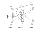
- FIG. 3 shows symbols of various variables used in this embodiment.
- the distance between the vehicle 10 and the left lane marking is dl [m]
- the distance between the vehicle 10 and the right lane marking is dr [m]
- the yaw angle of the vehicle 10 is ⁇ [rad]
- the road width (distance between the right and left lanes) is D [m]
- the vehicle speed is V [m / s]
- the yaw rate is ⁇ [rad / s]
- the lateral position which is the amount of lateral deviation of the vehicle 10 from the vehicle 10, is represented by z [m].
- the distance dl is referred to as the left division line position dl
- the distance dr is referred to as the right division line position dr.
- These left lane marking position dl and right lane marking position dr are information regarding the relative position of the vehicle 10 with respect to the lane marking line.
- the curvature ⁇ of the traveling route based on the lane marking recognized by the outside world recognition sensor 22 is expressed as ⁇ s
- the curvature ⁇ of the traveling route based on the road shape on which the vehicle 10 is traveling obtained by the navigation system 25 is expressed as ⁇ m. And.
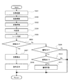
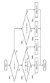
- FIG. 4 is a flowchart showing a processing procedure of lane keep control and lane departure warning control by the control unit 21.
- the microcomputer 21a of the control unit 21 executes the routine shown in the flowchart of FIG. 4 by interrupt processing at regular intervals, for example, every 50 ms.
- step S501 the control unit 21 uses the outside world recognition processing device 23 to form a division line including information on the left division line position dl, the right division line position dr, the yaw angle ⁇ , and the curvature ⁇ s. Information about is acquired as the first information.
- step S502 the control unit 21 determines the curvature ⁇ m of the road at the current position of the vehicle 10 based on the information regarding the road shape at the current position of the vehicle 10 acquired from the navigation system 25. It is also calculated, and the amount of change C [1 / m / m] of the curvature ⁇ m is calculated.
- the above-mentioned curvature ⁇ m and change amount C are second information regarding the curvature of the lane.
- the amount of change C is the amount of change in the curvature ⁇ m per unit moving distance of the vehicle 10. Then, when the moving distance of the vehicle 10 is expressed by s, the amount of change C is a value satisfying Equation 1.
- D / ds in Equation 1 is a differential value with respect to the moving distance s of the vehicle 10.
- the control unit 21 can obtain the curvature ⁇ m as the reciprocal of the radius of a circle passing through three nodes near the current position of the vehicle 10. Further, the control unit 21 calculates an approximate curve showing the relationship of the curvature ⁇ m with respect to the moving distance s by using, for example, the curvature ⁇ m calculated based on a plurality of nodes around the current position of the vehicle 10 and the distance between the nodes. The slope of the approximate curve at the current position of the vehicle 10 can be obtained as the amount of change C. At this time, the control unit 21 can save the curvature ⁇ m calculated at each time and correct the movement distance s by using the movement amount of the vehicle 10 to calculate the approximate curve.
- the control unit 21 can calculate the curvature ⁇ m using the map information in which the road shape is represented by the node and the link. Therefore, the map used by the navigation system 25 may be a map in which the road shape is represented by nodes and links, and it is not necessary to use a so-called high-precision map having information such as lanes and signs.
- control unit 21 uses a local map (for example, a road network map) around the vehicle 10 based on the surrounding environment such as a curb measured by using LiDAR or the like instead of the map information provided in the navigation system 25. Can be created. Then, the control unit 21 can calculate the curvature ⁇ m and the amount of change C as the second information based on the information of the created map. That is, the road shape information acquisition unit is not limited to the navigation system 25, and the control unit 21 can acquire the road shape by a sensor such as LiDAR provided separately from the outside world recognition sensor 22.
- a local map for example, a road network map
- the control unit 21 can calculate the curvature ⁇ m and the amount of change C as the second information based on the information of the created map. That is, the road shape information acquisition unit is not limited to the navigation system 25, and the control unit 21 can acquire the road shape by a sensor such as LiDAR provided separately from the outside world recognition sensor 22.
- the road shape information acquired by the control unit 21 from the navigation system 25 or the like is information on the shape of the road on which the vehicle 10 including the outside of the lane marking can travel, and is, for example, a guardrail or a curb outside the lane marking. It is information about the shape of the road whose boundary is determined by such factors. Further, the control unit 21 can use a radius of curvature 1 / ⁇ instead of the curvature ⁇ as an amount indicating the degree of bending of the lane (road). However, since the radius of curvature of the straight road becomes infinite and the data becomes difficult to handle in the arithmetic processing of the microcomputer 21a, the control unit 21 of the present embodiment uses the curvature ⁇ .
- step S503 the control unit 21 acquires information on the vehicle speed V and the yaw rate ⁇ of the vehicle 10 from the vehicle behavior detection device 26 as the third information regarding the behavior of the vehicle 10.
- step S504 the control unit 21 has step S501 (first information acquisition unit 211), step S502 (second information acquisition unit 212), and step S503 (third information acquisition unit 214).
- the reliability W (in other words, weighting) for each of the information acquired in 213) is set.
- the reliability W is an index value of the certainty of each information, and the calculation process of the reliability W by the control unit 21 will be described in detail later.
- step S505 lane estimation unit 215
- step S503 third information acquisition unit 211
- the third information acquired in 213) is weighted based on the reliability W set in step S504 (reliability setting unit 214), and the estimated values of the horizontal position z, the yaw angle ⁇ , the road width D, and the curvature ⁇ are obtained. Performs a state estimation calculation that is calculated as lane information. The calculation process of the lane information will be described in detail later.
- the control unit 21 estimates lane information based on the first information acquired from the outside world recognition sensor 22, the second information acquired from the navigation system 25, and the third information regarding the behavior of the vehicle 10. Therefore, the recognition performance of the lane marking can be improved, and the performance of the lane keep control can be improved. For example, even in an intersection where there is no lane marking, the control unit 21 can estimate the lane in which the vehicle 10 should travel and continue the lane keep control, and the area where the lane keep control can be performed is expanded. Further, since the control unit 21 weights based on the reliability W of each information used for estimating the lane information, it is possible to suppress the influence of the information having a large error on the estimation result, and the accurate information is estimated for the lane information. It can be incorporated into the lane information to improve the accuracy of the lane information.
- step S506 the control unit 21 proceeds to step S506, and whether or not the lane keep control is on, in other words, the driver of the vehicle 10 selects the automatic driving mode and specifies the execution of the lane keep control. Judge whether or not. Then, the control unit 21 proceeds to step S507 if the lane keep control is on, that is, in the automatic operation mode, and proceeds to step S509 if the lane keep control is off.
- step S507 the control unit 21 is required for the vehicle 10 to travel along the traveling lane based on the lane information obtained in step S505 (lane estimation unit 215).
- the target steering amount (in other words, the control command related to steering) is calculated.
- step S508 outputs a control command of the target steering amount (in other words, the target steering angle) obtained in step S507 to the steering control device 27, and then ends the control cycle.
- the steering control device 27 controls the steering actuator of the steering device 31 so as to realize the target steering amount commanded by the control unit 21.
- step S509 whether or not the lane departure warning control is in the on state, in other words, the driver of the vehicle 10 selects the driving support mode. Then, it is determined whether or not the implementation of the lane departure warning control is specified. Then, the control unit 21 proceeds to step S510 if the lane departure warning control is on, that is, in the driving support mode. On the other hand, the control unit 21 ends the control cycle when the control of the lane departure warning is off and both the automatic driving mode and the driving support mode are not selected.
- step S510 When the control unit 21 is in the lane departure warning control state, that is, in the driving support mode and proceeds to step S510, the vehicle 10 moves from the traveling lane based on the lane information obtained in step S505 (lane estimation unit 215). Determine if it is about to deviate. Then, when the vehicle 10 is about to deviate from the traveling lane, the control unit 21 proceeds to step S511 and outputs an operation command to the alarm device 28.
- the control unit 21 warns the driver of the vehicle 10 by operating the alarm device 28, the HUD device 29, the steering vibration device 30, and the like that the vehicle 10 is about to deviate from the traveling lane, and then sets the control cycle. finish.
- the control unit 21 activates the alarm device 28. The control cycle ends without any notice.
- the system is such that only one of the lane keep control and the lane departure warning control is operated.
- the lane estimation unit 215 in other words, the process in step S505 of FIG. 4 will be described in detail.
- the left division line position dl, the right division line position dr, the yaw angle ⁇ , and the curvature ⁇ s as the output y [k] (observed value)
- the curvature ⁇ m the vehicle speed V as the input u [k] (control input value)
- the yaw rate ⁇ control input value
- the amount of curvature change C the lateral position z and the yaw angle ⁇ as the state x [k] (estimated state value).
- Road width D, and curvature ⁇ road width D, and curvature ⁇ .
- x, u, and y are state vectors (state estimated values), input vectors (control input values), and output vectors (observed values), and T is a symbol representing a transposed matrix.
- the state equation showing the dynamics of the system can be expressed by the equations 5 and 6, and the observation equation expressing the output vector by using the state vector can be expressed by the equations 7 and 8.
- ⁇ t represents the time between samplings (in other words, the sampling period)
- v and w are the system noise of the mean value 0 covariance matrix Q and the observed noise of the mean value 0 covariance matrix R, respectively.
- the evaluation function J shown in the equation 9 is set as an index showing the certainty of the state estimation.
- T is the current sampling
- H is evaluated section length, in other words, the sampling number to be included in the evaluation function J
- S Q, S R, S P denotes the weight matrix.
- x ⁇ with a bending accent indicates that it is an estimated value (estimated state) of the state x
- x ⁇ with a bending accent with "-" as a superscript is an estimated value in the previous sampling. It represents that.
- the method of using the evaluation function J represented by the above equation 9 in the optimization calculation and obtaining the state estimation value that minimizes the value of the evaluation function J is a method called Moving Horizon estimation (MHE).
- MHE Moving Horizon estimation
- the first term on the right side of Equation 9 is a term for ensuring that the amount of change in the state estimate between each sampling matches the equation of state in Equation 6, and by minimizing this term, the dynamics of the system can be obtained.
- the state can be estimated according to the rules.
- the second term on the right side of the equation 9 is a term for making the relationship between the state estimated value and the observed value of each sampling match with the observed equation of the equation 8, and this term should be minimized.
- the state can be estimated according to the observed value.
- the third term on the right side of the equation 9 is a term for evaluating the amount of change from the state estimated value obtained in the previous sampling, and by minimizing this term, the information before the evaluation section length can be obtained. It can be incorporated into the estimation.
- Equation 9 the effect degree of each term of the right side of Equation 9 is given to the state estimation, weighting matrix S Q, S R, determined by S P.
- the Moving Horizon estimation expanded weight matrix S Q, as S R, using the inverse matrix of the covariance matrix of system noise and observation noise, also, as the weight matrix S P, from Equation 5 the system equation 8
- the inverse matrix of the error covariance matrix of the estimated state obtained when the Kalman filter is applied is used.
- the outlier is an estimated value.
- the estimated value may deviate significantly from the true value. Therefore, in the control unit 21 (lane estimation unit 215), the left division line position dl, the right division line position dr, the yaw angle ⁇ , the curvature ⁇ s, and the curvature ⁇ m, which are the observed values (in other words, the measured values), are outliers. If there is a high possibility, the weight of the observed value is reduced to estimate the state in which the influence of outliers is suppressed.
- FIG. 5 shows the correlation between the observed values, the estimated values, and the weights of the observed values.
- the alternate long and short dash line shows the estimated value when the state is estimated without considering the outliers
- the solid line shows the estimated value when the state is estimated with the weight of the outliers reduced.
- the dotted line indicates the true value
- the circle indicates the measured value.
- the lane estimation unit 215 calculates the weight matrix S R for the second term on the right side of the equation 9 based on the equation 10 using the reliability W calculated by the reliability setting unit 214.
- control unit 21 can also change the weight matrix S Q for the first term on the right side of the equation 9 according to the reliability W.
- the degree of influence of each term on the right side of Equation 9 on the state estimation is determined by the weight ratio of each term, if the weight for the first term is reduced and the weight for the second term is reduced, the weight is not changed as a result. There is a possibility that the estimation result will not be much different from the case.
- control unit 21 changes only the weight matrix S R for the second term on the right side of the equation 9 according to the reliability W.
- the process of calculating the reliability W by the control unit 21 (reliability setting unit 214) will be described later.
- FIG. 6 is a flowchart showing the processing contents in step S505 (lane estimation unit 215) of the flowchart of FIG. First, the control unit 21, in step S505a, the weighting matrix S Q of the terms right-hand side of Equation 9, S R, to calculate the S P.
- the control unit 21 can use a known solution method such as a sequential quadratic programming method or an interior point method, and if the sequential quadratic programming method is used, the solution can be solved at a relatively high speed. Can be sought.
- the control unit 21 can impose a predetermined constraint condition as described later in the calculation of the estimated value x ⁇ [k] (estimation of lane information).
- the evaluation function J will be the function shown in Equation 11 in order to explain the effect of changing the weight according to the reliability W in an easy-to-understand manner.
- the evaluation function J of the formula 9 has more terms to be added than the evaluation function J of the formula 11, and includes terms that are not in the quadratic form, so that the evaluation function J of the formula 11 is more complicated than the evaluation function J of the formula 11.
- the evaluation function J of Equation 11 similarly to the evaluation function J of Equation 11, by reducing the weight of the deviation value, the influence of the deviation value on the estimation result can be suppressed.
- the control unit 21 performs the Moving Horizon estimation to obtain the state estimation value by performing the optimization calculation that minimizes the value of the evaluation function J of the equation 9, but instead of the Moving Horizon estimation, the equation 5 Therefore, a known extended Kalman filter can be designed for the system shown in Equation 8 and the covariance matrix R used therein can be changed according to the reliability W.
- the extended Kalman filter can be designed for the system shown in Equation 8 and the covariance matrix R used therein can be changed according to the reliability W.
- FIG. 9 shows a state of sequential calculation in the extended Kalman filter in which the estimation result of the previous sampling is corrected by using the output and the input of the current sampling.
- FIG. 10 shows how the Moving Horizon estimate calculates the estimated value using all the inputs (control input values) and outputs (observed values) within a certain evaluation interval (in other words, within the estimated horizon).
- the control unit 21 employs Moving Horizon estimation instead of the extended Kalman filter.
- the control unit 21 can impose a constraint condition on the estimated value when calculating the estimated value that minimizes the value of the evaluation function J shown in the equation 9 in step S505B of the flowchart of FIG. 6 described above. ..
- the constraint condition of the estimated value expresses the condition that the estimated value must satisfy when calculating the estimated value that minimizes the evaluation function J by an equation or an inequality.
- the control unit 21 adds the following constraints to the estimated value. For example, when the vehicle 10 travels on a developed road such as a trunk road or an expressway, the curvature ⁇ of the traveling route does not change abruptly. Therefore, the control unit 21 applies the constraint condition shown in Equation 12 to the estimated value ⁇ ⁇ of the curvature ⁇ so that the amount of change in the estimated value ⁇ ⁇ of the curvature ⁇ is equal to or less than a certain value ( ⁇ max).
- Equation 12 kappa ⁇ - is an estimate of the curvature kappa at the previous sampling. Further, ⁇ max in Equation 12 is an upper limit value of the amount of change in curvature ⁇ per unit movement distance of the vehicle 10, and is set based on, for example, the maximum value of the curvature change rate of a general road.
- the control unit 21 can be calculated based on the amount of change in the curvature of the road to get the value of Derutakappa max from the map information, it changes the value of Derutakappa max at each sampling.
- the control unit 21 has an effect even if the observed value of the curvature ⁇ that deviates greatly from the actual value is used for the state estimation. It is possible to prevent the estimated value ⁇ ⁇ of the curvature ⁇ from deviating significantly from the actual value.
- the control unit 21 adds the constraint condition shown in Equation 13 to the estimated value z ⁇ of the horizontal position z so that the amount of change in the estimated value z ⁇ of the horizontal position z is equal to or less than a certain value ( ⁇ z max).
- Equation 13 z ⁇ -is the estimated value in the previous sampling. Further, ⁇ z max in Equation 13 is an upper limit value of the amount of change in the lateral position z per unit time. For example, the lateral position that can occur when the vehicle 10 is generally traveling along the traveling lane. It is a value based on the maximum value of the amount of change in z.
- the control unit 21 can change the upper limit value ⁇ z max according to the vehicle speed V of the vehicle 10.
- the control unit 21 observes, for example, the left division line position dl and / or the right division line position dr that greatly deviates from the actual value. Even if the value is used for state estimation, it is possible to prevent the estimated value z ⁇ of the horizontal position z from deviating significantly from the actual value due to the influence.
- control unit 21 adds the constraint condition shown in Equation 14 to the estimated value D ⁇ of the road width D so that the estimated value D ⁇ of the road width D is within a predetermined range.
- D min is the minimum value (lower limit value) of the road width D
- D max is the maximum value (upper limit value) of the road width D.
- the control unit 21 imposes a constraint condition that sets a lower limit and an upper limit on the estimated value D ⁇ of the road width D. For example, when the position of the white line other than the lane marking is measured, the estimated value of the road width D is actually measured due to the influence. It is possible to prevent a large deviation from the value.
- the control unit 21 has a reliability W which is an index value indicating the certainty (accuracy, accuracy) of the measurement result for each observed value (left and right division line positions dl, dr, yaw angle ⁇ , curvature ⁇ s, curvature ⁇ m). To set.
- the reliability W is a value from 0 to 1 (0 ⁇ W ⁇ 1), and the closer the value of the reliability W is to 1, the higher the certainty, and the closer the value of the reliability W is to 0, the lower the certainty. Is shown. That is, the control unit 21 can correctly estimate the state by using the observed value whose reliability W is close to 1 for the state estimation, and the observed value (in other words, the outlier) whose reliability W is close to 0 is used for the state estimation. There is a high possibility that an error will occur in the state estimation by using it.
- the reliability basic value Wtmp is corrected according to the degree of variation of the observed value y, the running state of the vehicle 10, the surrounding environment of the vehicle 10, and the final reliability W is obtained.
- the control unit 21 calculates the reliability base value Wtmp according to Equation 15.
- ⁇ is the standard deviation of the error between the observed value y and the estimated value y ⁇
- ⁇ 2 is the variance of the error between the observed value y and the estimated value y ⁇ .
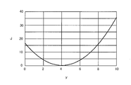
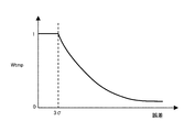
- FIG. 11 shows the correlation between the error between the observed value y and the estimated value y ⁇ and the reliability basic value Wtmp.
- the error between the observed value y and the estimated value y ⁇ is smaller than 3 ⁇ , the error is sufficiently small and the target observed value y is sufficiently reliable, so that the control unit 21 has the maximum reliability base value Wtmp.
- the control unit 21 has a reliability basic value as the error becomes larger. Wtmp is gradually reduced to reduce the influence of the unreliable observation value y on the state estimation.
- 3 ⁇ is used as the error standard, but the error is not limited to 3 ⁇ .
- ⁇ is used for calculating the reliability basic value Wtmp instead of 3 ⁇ , and conversely, the state using information with a relatively large error. If you want to estimate, for example, 5 ⁇ can be used to calculate the reliability base value Wtmp instead of 3 ⁇ .
- the control unit 21 sets the reliability basic value Wtmp according to the error between the observed value y and the estimated value y ⁇ , so that the weight is set according to the error.
- the observed value y may not be reliable even when the error is small.
- the weight is set according to the error, once the estimation fails and the estimated value y ⁇ deviates significantly from the true value, the weight becomes small even if the correct value is measured, and the estimated value y ⁇ cannot be corrected. there is a possibility.
- the control unit 21 corrects the reliability basic value Wtmp according to the degree of variation in the observed values, the running state of the vehicle 10, the surrounding environment of the vehicle 10, and the like, and sets the final reliability W.
- FIG. 12 shows a correction pattern of the reliability basic value Wtmp.
- the control unit 21 determines that the observed value is unreliable, the control unit 21 corrects the reliability W so that it is smaller than the basic reliability value Wtmp, as shown by a dotted line in FIG.
- a method of setting the reliability W to be smaller than the reliability basic value Wtmp for example, a method of setting the square value of the reliability basic value Wtmp as the reliability W, or a method of setting 0 to 1 with respect to the reliability basic value Wtmp. There is a method of setting the value obtained by multiplying the constants between them as the reliability W.
- the control unit 21 sets the square value of the reliability base value Wtmp as the reliability W, the influence of the error on the reliability W can be amplified. Further, when the control unit 21 sets the value obtained by multiplying the basic reliability value Wtmp by a constant as the reliability W, the influence on the state estimation can be reduced at a constant rate regardless of the error.
- the control unit 21 can change the method of setting the reliability W to be smaller than the basic reliability value Wtmp, depending on the target observed value, the condition for determining that the observed value is unreliable, and the like. Further, when the control unit 21 does not obtain both the judgment result that the observed value is sufficiently reliable and the judgment result that the observed value is unreliable, the reliability W is shown by the solid line in FIG. Is matched with the reliability base value Wtmp.
- FIG. 13 shows the correction conditions for the left and right division line positions dl and the reliability W of dr measured by using the outside world recognition sensor 22, and the reliability W as the correction result.
- a method of making the reliability W of the left and right division line positions dl and dr smaller than the reliability basic value Wtmp a method of setting the square value of the reliability basic value Wtmp to the reliability W is used. This is to suppress the adverse effect of the measurement results of the left and right division line positions dl and dr on the state estimation by amplifying the influence of the error on the reliability W.
- the outside world recognition sensor 22 cannot measure the left and right lane marking positions dl and dr because there is no lane marking in the intersection, and the left and right lane markings cannot be measured.
- the reliability of the measurement results of the lane marking positions dl and dr is low. Therefore, when the control unit 21 determines that the distance between the vehicle 10 and the intersection is less than a certain value and the vehicle 10 is near the intersection based on the information from the navigation system 25, the reliability of the left and right lane marking positions dl and dr is determined.
- control unit 21 If the control unit 21 suddenly changes the reliability W from the basic reliability value Wtmp to the square value of the basic reliability value Wtmp, the estimated value also suddenly changes, which may impair the stability of steering control. There is. Therefore, the control unit 21 can gradually change the reliability W between the basic reliability value Wtmp and the squared value of the basic reliability value Wtmp.
- FIG. 14 is a diagram for explaining a method of gradually changing the reliability W.
- the control unit 21 sets two threshold values for the condition for correcting the reliability W, and sets the reliability W from the reliability basic value Wtmp until the correction condition reaches the first threshold value to the second threshold value. Gradually change to the square value of the base value Wtmp.
- the control unit 21 starts to reduce the reliability W from the time when the distance between the vehicle 10 and the intersection decreases to the first threshold value. Then, the control unit 21 has a reliability W so that the reliability W reaches the square value of the reliability basic value Wtmp when the distance between the vehicle 10 and the intersection reaches the second threshold value shorter than the first threshold value. Is continuously changed from the reliability basic value Wtmp to the square value of the reliability basic value Wtmp.
- the control unit 21 can continuously change the reliability W from the basic reliability value Wtmp to the square value of the basic reliability value Wtmp by, for example, interpolation calculation using a cubic function or the like. ..
- the processing for suppressing a sudden change in reliability W based on the establishment of the correction condition includes conditions other than the intersections described below and other than the left and right division line positions dl and dr. It is clear that it can also be applied to the correction of the reliability W for the observed value of.
- the process of correcting the degree W according to the vehicle speed V will be described.
- the vehicle 10 may be stopped at the stop line of the intersection or immediately before the stop due to a traffic light or the like, or may be stopped behind the stopped preceding vehicle.
- the outside world recognition sensor 22 cannot measure the left and right lane marking positions dl and dr because there is no lane marking in the intersection. Further, when the vehicle 10 is stopped behind the preceding vehicle, the distance between the vehicle and the preceding vehicle is relatively short. In this case, the preceding vehicle blocks a part of the area recognizable by the outside world recognition sensor 22, so that the outside world is present. The recognition sensor 22 may not be able to correctly measure the left and right division line positions dl and dr.
- FIG. 15 is a diagram showing a state in which the preceding vehicle narrows the recognizable area of the outside world recognition sensor 22, and the portion behind the preceding vehicle when viewed from the outside world recognition sensor 22 cannot be measured by the outside world recognition sensor 22. Become an area. Therefore, when the control unit 21 determines that the vehicle speed V is lower than the predetermined speed and the vehicle 10 is stopped, the reliability W of the left and right lane marking positions dl and dr is set to the square value of the reliability basic value Wtmp. To do.
- the condition [T-1-3] of FIG. 13 that is, the setting of the reliability W of the left and right division line positions dl and dr when it can be estimated that the left and right division line positions dl and dr can be measured correctly.
- the control unit 21 sets the reliability W to 1 if the left and right division line positions dl and dr can be measured correctly, and the observed values of the left and right division line positions dl and dr. Can be incorporated into the state estimation to proceed with the correction of the estimated value.
- the measurement variations of the left and right division line positions dl, dr, yaw angle ⁇ , and curvature ⁇ s are all small, and the measured road width D (in other words, the absolute of the left and right division line positions dl and dr).
- the reliability W of the left and right division line positions dl and dr is set to 1.
- the control unit 21 stores, for example, the observed values up to the past for a certain period of time in the memory, calculates the variance using the saved observed values, and determines the magnitude of the measurement variation of the observed values based on the variance. be able to. Further, the control unit 21 can use it for determining the measurement variation of the observed value by sequentially calculating the variance such that the older the data of the observed value is in the time series, the more the influence is attenuated.
- the control unit 21 determines the degree of variation in the yaw angle ⁇ and the degree of variation in the curvature ⁇ s under the condition [T-1-3] of FIG.
- the fixed range of the road width D is a value based on the road width of a general road, and is, for example, a range of 2.5 m or more and 4 m or less.
- the control unit 21 measures the left and right lane marking positions when the measured road width D is within a certain range when the measurement variability of one lane marking is small and the measurement variability of the curvature ⁇ s is also small.
- the reliability W of the lane marking position with less variation, that is, the lane marking position that can be estimated to be measured correctly is set to 1, and the reliability W of the other lane marking position is set to the reliability base value Wtmp.
- the condition [T-1-4] in FIG. 13 and In [T-1-5] the degree of variation in the yaw angle ⁇ is excluded from the conditions.
- the process of setting the reliability W of the left and right lane marking positions dl and dr according to the relative distance between the vehicle 10 and the preceding vehicle under the condition [T-1-6] of FIG. 13 will be described.
- the preceding vehicle blocks the area recognizable by the outside world recognition sensor 22, so that the outside world recognition sensor 22 correctly sets the left and right division line positions dl and dr. It may not be possible to measure. Therefore, when the distance to the preceding vehicle recognized by the outside world recognition sensor 22 is shorter than a certain value, the control unit 21 sets the reliability W of the left and right lane marking positions dl and dr as the square value of the reliability basic value Wtmp. Set to.
- the control unit 21 trusts the left division line position dl and the right division line position dr.
- Set the degree W to the square value of the reliability base value Wtmp.
- the correction process of the reliability W under the above conditions [T-1-3]-[T-1-5] and [T-1-7] is performed on the left division line position dl and the left division line position dl according to the variation of the observed values. This is a process for correcting the reliability W of the right marking line position dr.
- control unit 21 If the control unit 21 does not meet any of the conditions [T-1-1]-[T-1-7] shown in FIG. 13, it is determined that the condition [T-1-8] shown in FIG. 13 is met.
- the control unit 21 corrects the reliability W of the left and right division line positions dl and dr for each condition [T-1-1]-[T-1-8] of FIG. 13, so that the left and right division line positions dl and dr.
- the measurement results of the left and right lane markings dl and dr can be incorporated into the state estimation (lane estimation), and if the measurement is not correct, the measurement results of the left and right lane markings dl and dr.
- State estimation that suppresses the influence of
- FIG. 16 shows the correction conditions for the reliability W of the yaw angle ⁇ measured using the external world recognition sensor 22, and the reliability W as the correction result.
- the control unit 21 multiplies the reliability basic value Wtmp by a constant value (for example, 10 -3 ) to obtain the reliability W.
- control unit 21 calculates the yaw angle ⁇ using the outside world recognition sensor 22, it is generally calculated using the information of the left and right division line positions dl and dr, so that the yaw angle ⁇ is calculated even if the error is small.
- the measurement result may not be reliable. Therefore, the adverse effect of the measurement result of the yaw angle ⁇ on the estimated value cannot be completely removed only by amplifying the influence of the error on the reliability W by the control unit 21.
- the correction process will be described.
- the vehicle 10 may be stopped at the stop line of the intersection or immediately before the stop due to a traffic light or the like, or may be stopped behind the stopped preceding vehicle.
- the outside world recognition sensor 22 cannot measure the left and right lane marking positions dl and dr because there is no lane marking in the intersection. Further, when the vehicle 10 is stopped behind the preceding vehicle, the distance between the vehicle and the preceding vehicle is relatively short. In this case, as shown in FIG. 15, a part of the region recognizable by the outside world recognition sensor 22. Since the preceding vehicle blocks the above, the outside world recognition sensor 22 may not be able to correctly measure the left and right division line positions dl and dr.
- the control unit 21, reliability determining unit 214 when the vehicle speed V is determined that the vehicle 10 below a predetermined vehicle speed is stopped, the reliability W of the yaw angle ⁇ to the reliability baseline Wtmp 10 - It is a value multiplied by 3.
- the condition [T-2-3] in FIG. 16 that is, the setting of the reliability W of the yaw angle ⁇ when it can be estimated that the yaw angle ⁇ can be measured correctly, in other words, the variation of the observed values.
- the process of correcting the reliability W according to the above will be described. If it can be determined that the yaw angle ⁇ can be measured correctly even when the error between the observed value and the estimated value is large, the control unit 21 sets the reliability to 1 and incorporates the observed value of the yaw angle ⁇ into the state estimation. , You can proceed with the correction of the estimated value. Therefore, the control unit 21 sets the reliability W of the yaw angle ⁇ to 1 when the measurement variations of the left and right division line positions dl, dr, the yaw angle ⁇ , and the curvature ⁇ s are all small.
- the condition [T-2-3] of FIG. 16 includes the degree of variation of the left and right division line positions dl and dr in the determination condition. Further, since the control unit 21 calculates the curvature ⁇ s based on the information of the left and right division line positions dl and dr, if the measurement results of the curvature ⁇ s vary, the yaw angle ⁇ may not be calculated correctly. Therefore, the condition [T-2-3] of FIG. 16 also includes the degree of variation of the curvature ⁇ s in the determination condition.
- the control unit 21 sets the reliability W of the yaw angle ⁇ as the value obtained by multiplying the reliability basic value Wtmp by 10 -3. ..
- the control unit 21 calculates the yaw angle ⁇ using the outside world recognition sensor 22, the information of the left and right division line positions dl and dr is generally used, and therefore, among the left and right division line positions dl and dr. If there is a large variation in either one, the control unit 21 cannot correctly calculate the yaw angle ⁇ . Therefore, when the variation is large in either one of the left and right division line positions dl and dr, the control unit 21 sets the reliability W of the yaw angle ⁇ as the value obtained by multiplying the reliability basic value Wtmp by 10 -3.
- the reliability W of the angle ⁇ be the reliability base value Wtmp.
- the control unit 21 can correctly measure the yaw angle ⁇ by correcting the reliability W of the yaw angle ⁇ for each of the conditions [T-2-1]-[T-2-6] shown in FIG. In the case, the measurement result of the yaw angle ⁇ can be incorporated into the state estimation (lane estimation), and if the measurement is not performed correctly, the state estimation (lane estimation) can be performed in which the influence of the measurement result of the yaw angle ⁇ is suppressed.
- FIG. 17 shows the correction conditions for the reliability W of the curvature ⁇ s measured using the external world recognition sensor 22, and the reliability W as the correction result.
- the control unit 21 multiplies the reliability basic value Wtmp by a constant value (for example, 10 -3 ) to obtain the reliability W (for example, 10 -3).
- the method of setting W Wtmp ⁇ 10 -3 ) is adopted.
- control unit 21 calculates the curvature ⁇ s using the outside world recognition sensor 22, it is generally calculated using the information of the left and right division line positions dl and dr, so that the measurement result of the curvature ⁇ s is small even if the error is small. May be unreliable. Therefore, the adverse effect of the measurement result of the curvature ⁇ s on the estimated value cannot be completely removed only by amplifying the influence of the error on the reliability W by the control unit 21.
- the control unit 21 calculates the curvature ⁇ s based on the information of the left and right division line positions dl and dr measured by using the outside world recognition sensor 22.
- the control unit 21 trusts the reliability W of the curvature ⁇ s.
- the value is the base value Wtmp multiplied by 10 -3.
- the control unit 21 determines that the distance between the vehicle 10 and the intersection is less than a certain value and the vehicle 10 is near the intersection based on the information from the navigation system 25, the curvature measured by using the outside world recognition sensor 22.
- the reliability W of ⁇ s be the value obtained by multiplying the basic reliability value Wtmp by 10 -3.
- the vehicle 10 may be stopped at the stop line of the intersection or immediately before the stop due to a traffic light or the like, or may be stopped behind the stopped preceding vehicle.
- the outside world recognition sensor 22 cannot measure the left and right lane marking positions dl and dr because there is no lane marking in the intersection. Further, when the vehicle 10 is stopped behind the preceding vehicle, the distance between the vehicle and the preceding vehicle is relatively short. In this case, as shown in FIG. 15, a part of the region recognizable by the outside world recognition sensor 22. Since the preceding vehicle blocks the above, the outside world recognition sensor 22 may not be able to correctly measure the left and right division line positions dl and dr.
- the control unit 21 determines that the vehicle speed V is sufficiently low and the vehicle 10 is stopped, the reliability W of the curvature ⁇ s measured by the outside world recognition sensor 22 is set to the reliability basic value Wtmp by 10 -3. Is the value multiplied by.
- the control unit 21 sets the reliability W of the curvature ⁇ s as the value obtained by multiplying the reliability basic value Wtmp by 10 -3.
- the control unit 21 calculates the curvature ⁇ s using the outside world recognition sensor 22, generally, the left and right division line positions dl and / or one of the left and right division line positions measured using the outside world recognition sensor 22 are used. Therefore, when the measurement variation of both the left and right division line positions dl and dr is large, the control unit 21 cannot correctly measure the curvature ⁇ s. Therefore, when the measurement variation of both the left and right division line positions dl and dr is large, the control unit 21 sets the reliability W of the curvature ⁇ s as the value obtained by multiplying the reliability basic value Wtmp by 10 -3.
- the control unit 21 measures the curvature ⁇ s using the outside world recognition sensor 22, and also measures the curvature ⁇ m based on the shape (map information) of the road on which the vehicle 10 is traveling obtained by the navigation system 25.
- control unit 21 can calculate the curvature ⁇ d of the traveling locus of the vehicle 10 based on the vehicle behavior, and when the vehicle 10 is traveling along the lane marking, the outside world recognition sensor 22 and the navigation system 25 are used.
- the difference between the curvatures ⁇ s and ⁇ m of the travel path measured using the vehicle and the curvature ⁇ d of the travel trajectory based on the vehicle behavior is sufficiently small. Therefore, the control unit 21 compares the curvature ⁇ s calculated by using the outside world recognition sensor 22 with the curvature ⁇ m obtained from the map information and the curvature ⁇ d calculated from the behavior of the vehicle 10, and uses the outside world recognition sensor 22.
- the reliability W of the curvature ⁇ s calculated using the outside world recognition sensor 22 is set as the value obtained by multiplying the reliability basic value Wtmp by 10 -3. The method of determining the certainty of the curvature ⁇ s will be described in detail later.
- the reliability W of the curvature ⁇ s calculated using the recognition sensor 22 is defined as the reliability basic value Wtmp.
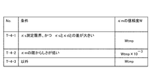
- FIG. 18 shows the correction conditions for the reliability W of the curvature ⁇ m obtained from the map information and the reliability W as the correction result.
- the error of the curvature ⁇ m acquired from the map information includes an error caused by a positioning error using GPS, an error caused when calculating the curvature ⁇ m from a plurality of node points, and an error possessed by the map information itself.
- the control unit 21 cannot determine the presence or absence of these errors by comparing the curvature ⁇ m obtained from the map information with the estimated value, and the observed value is estimated only by amplifying the influence of the error on the reliability W. This is because the adverse effect on the value cannot be completely removed.
- the curvature ⁇ s calculated by using the external world recognition sensor 22 exceeds the measurement limit, and the difference between the curvature ⁇ s and the curvature ⁇ d of the traveling locus calculated from the behavior of the vehicle 10 is equal to or more than a certain value. If the curvature ⁇ s is large and there is a high possibility that the curvature ⁇ s is incorrect, the reliability W of the curvature ⁇ m obtained from the map information is used as the reliability basis so that the lane estimation is performed based on the curvature ⁇ m obtained from the map information if there is no error. The value is Wtmp.
- the control unit 21 obtains the curvature ⁇ s as the curvature ⁇ of the traveling path by using the outside world recognition sensor 22 together with the curvature ⁇ m based on the map information. Further, the control unit 21 can calculate the curvature ⁇ d of the traveling locus of the vehicle 10 based on the vehicle behavior.
- the control unit 21 compares the curvature ⁇ s calculated using the outside world recognition sensor 22, the curvature ⁇ m obtained from the map information, and the curvature ⁇ d calculated based on the behavior of the vehicle 10, and confirms the curvature ⁇ m obtained from the map information. If it is judged that the likelihood is low, the reliability W of the curvature ⁇ m obtained from the map information is set as the value obtained by multiplying the basic reliability value Wtmp by 10 -3. The method of determining the certainty of the curvature ⁇ m will be described in detail later.
- the control unit 21 determines that the condition [T-4-3] of FIG. 18 is met, and maps the map.
- the reliability W of the curvature ⁇ m obtained from the information be the reliability basic value Wtmp.
- the control unit 21 compares the certainty of the curvature ⁇ s and ⁇ m with the curvature ⁇ s calculated by using the external world recognition sensor 22, the curvature ⁇ m obtained from the map information, and the curvature ⁇ d of the traveling locus calculated from the behavior of the vehicle 10. Judge with.
- the control unit 21 calculates the curvature ⁇ d of the traveling locus according to the mathematical formula 16.
- ⁇ is the steering angle
- A is the stability factor
- W b is the wheelbase
- V is the vehicle speed.
- the flowchart of FIG. 19 shows a procedure for calculating the certainty JDG ⁇ s of the curvature ⁇ s used for correcting the reliability W of the curvature ⁇ s measured using the external world recognition sensor 22 (that is, the condition [T-3-6] of FIG. 17). Is shown.
- the control unit 21 sets JDG ⁇ s to 1 when it is determined that the certainty of the curvature ⁇ s is high, and sets JDG ⁇ s to 0 when it is determined that the certainty of the curvature ⁇ s is low.
- step S601 the control unit 21 determines whether or not the previous value of the certainty JDG ⁇ s of the curvature ⁇ s is 1. Then, the control unit 21 proceeds to step S602 if the previous value of the certainty JDG ⁇ s of the curvature ⁇ s is 1, and if the previous value of the certainty JDG ⁇ s of the curvature ⁇ s is not 1, (in other words, the certainty of the curvature ⁇ s JDG ⁇ s). If the previous value of is 0), the process proceeds to step S605.
- step S602 the control unit 21 has an absolute value of the difference between the curvature ⁇ s and the curvature ⁇ d larger than the threshold Th1 and an absolute value of the difference between the curvature ⁇ s and the curvature ⁇ d is the absolute value of the difference between the curvature ⁇ m and the curvature ⁇ d. It is determined whether or not the first determination condition that the value is larger than the value is satisfied. When the first determination condition is satisfied, that is, the curvature ⁇ s calculated by using the external world recognition sensor 22 deviates significantly from the curvature ⁇ d of the traveling locus, and the deviation amount is the curvature obtained from the map information. When it is larger than the deviation amount of the traveling locus of ⁇ m with respect to the curvature ⁇ d, the certainty of the curvature ⁇ s is low (in other words, it can be estimated that the curvature ⁇ s cannot be measured correctly).
- step S603 sets the certainty JDG ⁇ s of the curvature ⁇ s to 0.
- the certainty of the curvature ⁇ s is high (in other words, it can be estimated that the curvature ⁇ s can be measured correctly), so that the control unit 21 steps. Proceed to S604 and keep the certainty JDG ⁇ s of curvature ⁇ s at 1.
- step S601 determines in step S601 that the previous value of the certainty JDG ⁇ s of the curvature ⁇ s is not 1, and proceeds to step S605, the absolute value of the difference between the curvature ⁇ s and the curvature ⁇ d is smaller than the threshold value Th1. It is determined whether or not the second determination condition is satisfied.
- the second determination condition is satisfied, that is, when the deviation amount between the curvature ⁇ s calculated by using the outside world recognition sensor 22 and the curvature ⁇ d of the traveling locus is less than a certain value, the outside world recognition sensor 22 is used. The probability of the calculated curvature ⁇ s is high.
- step S606 sets the certainty JDG ⁇ s of the curvature ⁇ s to 1.
- the control unit 21 proceeds to step S607 and keeps the certainty JDG ⁇ s of the curvature ⁇ s at 0.
- the control unit 21 sets the certainty JDG ⁇ s of the curvature ⁇ s as described above, and determines whether or not the condition [T-3-6] of FIG. 17 is satisfied based on the certainty JDG ⁇ s. That is, if the certainty JDG ⁇ s is 0, the control unit 21 determines that the certainty of the curvature ⁇ s is low, and sets the reliability W of the curvature ⁇ s calculated using the outside world recognition sensor 22 to the reliability basic value Wtmp. The value is multiplied by 10 -3.
- the flowchart of FIG. 20 shows a procedure for calculating the certainty JDG ⁇ m of the curvature ⁇ m used for correcting the reliability W of the curvature ⁇ m obtained from the map information (condition [T-4-2] of FIG. 18).
- the control unit 21 sets JDG ⁇ m to 1 when it is determined that the certainty of the curvature ⁇ m is high, and sets JDG ⁇ m to 0 when it is determined that the certainty of the curvature ⁇ m is low.
- step S701 the control unit 21 determines whether or not the previous value of the certainty JDG ⁇ m of the curvature ⁇ m is 1. Then, the control unit 21 proceeds to step S702 if the previous value of the certainty JDG ⁇ m of the curvature ⁇ m is 1, and if the previous value of the certainty JDG ⁇ m of the curvature ⁇ m is not 1 (in other words, the certainty JDG ⁇ m of the curvature ⁇ m). If the previous value of is 0), the process proceeds to step S705.
- the control unit 21 has an absolute value of the difference between the curvature ⁇ m and the curvature ⁇ d larger than the threshold Th2, and an absolute value of the difference between the curvature ⁇ m and the curvature ⁇ d is the absolute value of the difference between the curvature ⁇ s and the curvature ⁇ d. It is determined whether or not the first determination condition that the value is larger than the value is satisfied. When the first determination condition is satisfied, that is, the curvature ⁇ m obtained from the map information deviates significantly from the curvature ⁇ d of the traveling locus, and the deviation amount is the curvature calculated using the external world recognition sensor 22.
- step S703 sets the certainty JDG ⁇ m of the curvature ⁇ m to 0.
- the control unit 21 sets the control unit 21 in step S704. Proceed to, and hold the certainty JDG ⁇ m of curvature ⁇ m at 1.
- step S701 determines in step S701 that the previous value of the certainty JDG ⁇ m of the curvature ⁇ m is not 1, and proceeds to step S705, the absolute value of the difference between the curvature ⁇ m and the curvature ⁇ d is smaller than the threshold value Th2. It is determined whether or not the second determination condition is satisfied.
- the second judgment condition is satisfied, that is, when the deviation amount between the curvature ⁇ m obtained from the map information and the curvature ⁇ d of the traveling locus is less than a certain value, the certainty of the curvature ⁇ m obtained from the map information is It is in a high state.
- step S706 sets the certainty JDG ⁇ m of the curvature ⁇ m to 1.
- the control unit 21 proceeds to step S707 and holds the certainty JDG ⁇ m of the curvature ⁇ m at 0.
- the control unit 21 sets the certainty JDG ⁇ m of the curvature ⁇ m as described above, and determines whether or not the condition [T-4-2] of FIG. 18 is satisfied based on the certainty JDG ⁇ m. That is, if the certainty JDG ⁇ m is 0, the control unit 21 determines that the certainty of the curvature ⁇ m is low, and sets the reliability W of the curvature ⁇ m obtained from the map information to the reliability basic value Wtmp of 10 -3 . The value is multiplied.
- the vehicle motion control system of the above embodiment includes a navigation system 25 as a road shape information acquisition unit, but does not have a function of providing guidance on the current position or route guidance to the destination, and the current position of the vehicle 10 is not provided. It is possible to provide a road shape information acquisition unit composed of a position information acquisition device such as GPS for acquiring the above and map information.
- the lane estimation device can also be applied to the lane keep control (lane departure prevention support system) that performs steering control only when a lane departure is detected.
- the control unit 21 outputs a steering angle command for lane keeping control to the steering control device 27, but the steering angle command for lane keeping control is output to VMC (Vehicle Motion Controller: vehicle motion control). It can be a system that outputs to a device) or the like.
Landscapes
- Engineering & Computer Science (AREA)
- Physics & Mathematics (AREA)
- Transportation (AREA)
- Mechanical Engineering (AREA)
- Automation & Control Theory (AREA)
- General Physics & Mathematics (AREA)
- Theoretical Computer Science (AREA)
- Multimedia (AREA)
- Mathematical Physics (AREA)
- Chemical & Material Sciences (AREA)
- Combustion & Propulsion (AREA)
- Radar, Positioning & Navigation (AREA)
- Remote Sensing (AREA)
- Quality & Reliability (AREA)
- Human Computer Interaction (AREA)
- Traffic Control Systems (AREA)
- Steering Control In Accordance With Driving Conditions (AREA)
Abstract
本発明に係る車両制御装置、車両制御方法、車両運動制御システム、及びレーン推定装置は、外界認識部より取得した外界情報に基づいて、車両が走行する車線を区画する区画線に関する第1情報を取得し、道路形状情報取得部から取得した道路形状に関する情報に基づいて車線の曲率に関する第2情報を取得し、車両運動状態検出部から取得した車両の運動状態に関する物理量に基づいて車両の挙動に関する第3情報を取得し、第1情報と第2情報と第3情報とに基づいて、区画線の曲率に関する情報、及び、区画線に対する車両の相対位置に関する情報を含む、レーン情報を推定する。
Description
本発明は、車両制御装置、車両制御方法、車両運動制御システム、及びレーン推定装置に関する。
特許文献1の運転支援装置は、車載カメラによる撮影画像を取得する画像取得部と、撮影画像に基づいて、自車両が走行する車線を区画する区画線を認識する区画線認識部と、道路情報を取得する道路情報取得部と、道路情報に基づき、区画線認識部により認識された区画線の信頼度を設定する信頼度設定部と、認識された区画線に基づき、自車両の運転支援を実行させるとともに、信頼度に応じて、当該運転支援における制御内容を異ならせる運転支援部と、を備える。
ところで、車載カメラによる撮影画像から抽出した区画線の情報に基づきレーンキープ制御を実施するシステムでは、区画線を高い精度で安定的に認識することが難しく、また、交差点内などの区画線が存在しないときにはレーンキープ制御の継続が困難になるという問題があった。
本発明は、従来の実情に鑑みてなされたものであり、その目的は、区画線の認識性能を向上させることができる、車両制御装置、車両制御方法、車両運動制御システム、及びレーン推定装置を提供することにある。
本発明によれば、その1つの態様において、外界認識部より取得した外界情報に基づいて、車両が走行する車線を区画する区画線に関する第1情報を取得し、道路形状情報取得部から取得した道路形状に関する情報に基づいて、前記車線の曲率に関する第2情報を取得し、車両運動状態検出部から取得した前記車両の運動状態に関する物理量に基づいて、前記車両の挙動に関する第3情報を取得し、前記第1情報と、前記第2情報と、前記第3情報と、に基づいて、前記区画線の曲率に関する情報、及び、前記区画線に対する前記車両の相対位置に関する情報を含むレーン情報を推定する。
本発明によれば、区画線の認識性能が向上し、レーンキープ制御の性能を改善できる。
以下、本発明に係る車両制御装置、車両制御方法、車両運動制御システム、及びレーン推定装置の実施形態を、図面に基づいて説明する。
図1は、車両(自動車)10が備える車両運動制御システム20の一態様を示すシステムブロック図である。
図1は、車両(自動車)10が備える車両運動制御システム20の一態様を示すシステムブロック図である。
車両運動制御システム20は、ドライバによるステアリングホイール11の操作によらずに車両10が走行車線に沿って走行するように操舵制御、換言すれば、レーンキープ制御を行う自動運転モードと、車両10が走行車線から逸脱しそうになったことをドライバに通知する運転支援モードのうち、少なくともいずれか一方を有する。
なお、自動運転モードは、前述した操舵制御とともに車速制御を行うモードとすることができる。
なお、自動運転モードは、前述した操舵制御とともに車速制御を行うモードとすることができる。
車両運動制御システム20は、車両制御装置の一態様としてのコントロールユニット21を備える。
コントロールユニット21は、プロセッサ、メモリ、I/O、これらを接続するバスを備えるマイクロコンピュータ21aを主体とする電子制御装置であり、コントロール部としてのマイクロコンピュータ21aは、入力情報に基づき演算を行って演算結果としての制御指令を出力することで、操舵制御を含む車両制御を実施する。
コントロールユニット21は、プロセッサ、メモリ、I/O、これらを接続するバスを備えるマイクロコンピュータ21aを主体とする電子制御装置であり、コントロール部としてのマイクロコンピュータ21aは、入力情報に基づき演算を行って演算結果としての制御指令を出力することで、操舵制御を含む車両制御を実施する。
外界認識センサ22は、車両10(自車)の前方を測定して、車両10が走行している車線の左右を区画するために道路上に引かれた区画線(例えば、白線若しくは黄線)と、車両10の前方に存在する物体とを検出し、更に、車両10から区画線までの相対距離及び車両10から物体までの相対距離を測定する。
外界認識センサ22として、例えば、ステレオカメラやLiDAR(Light Detection and Ranging、Laser Imaging Detection and Ranging)など、車両前方の物体の形状及び車両10から物体までの距離の両方が測定可能なセンサを用いる。
また、外界認識センサ22を、単眼カメラやミリ波レーダー、超音波センサなど、車両前方の物体の形状と物体までの距離とのいずれか一方を測定可能なセンサを複数組み合わせて構成することができる。
外界認識センサ22として、例えば、ステレオカメラやLiDAR(Light Detection and Ranging、Laser Imaging Detection and Ranging)など、車両前方の物体の形状及び車両10から物体までの距離の両方が測定可能なセンサを用いる。
また、外界認識センサ22を、単眼カメラやミリ波レーダー、超音波センサなど、車両前方の物体の形状と物体までの距離とのいずれか一方を測定可能なセンサを複数組み合わせて構成することができる。
外界認識処理装置23は、外界認識センサ22が検出した区画線の情報に基づき、車両10と左右の区画線との相対的な距離、車両10のヨー角、車線(換言すれば、走行経路)の曲率に相当する区画線の曲率を算出する。
更に、外界認識処理装置23は、外界認識センサ22が検出した車両10の前方に存在する物体の情報に基づいて、車両10の前方を走行する先行車を認識し、車両10と先行車との相対距離を算出する。
更に、外界認識処理装置23は、外界認識センサ22が検出した車両10の前方に存在する物体の情報に基づいて、車両10の前方を走行する先行車を認識し、車両10と先行車との相対距離を算出する。
上記の外界認識センサ22及び外界認識処理装置23は、車両10の外界情報を認識する外界認識部を構成する。
また、外界認識処理装置23が算出する、車両10と左右の区画線との相対的な距離、ヨー角、区画線の曲率の情報は区画線に関する情報であり、本願では、これらの外界認識センサ22を用いて求めた区画線に関する情報を第1情報と称する。
また、外界認識処理装置23が算出する、車両10と左右の区画線との相対的な距離、ヨー角、区画線の曲率の情報は区画線に関する情報であり、本願では、これらの外界認識センサ22を用いて求めた区画線に関する情報を第1情報と称する。
GPS(Global Positioning System)24は、車両10と複数のGPS衛星との位置関係を測定し、測定結果に基づき、車両10の現在位置を示す緯度及び経度、更に、車両10の方向角を計算する。
ナビゲーションシステム25は、GPS24から取得した車両10の現在位置に関する情報と地図情報とに基づき、車両10の周辺の道路地図に車両10の現在位置を示すマーカを重ねた地図画面を、付属する液晶ディスプレイに表示する。
また、ナビゲーションシステム25は、現在位置からドライバが指定した目的地までの最適な誘導経路を探索し、誘導経路を地図画面に重畳表示するとともに、地図画面への分岐情報の表示や発話(換言すれば、音声)などによって、ドライバに進路変更の案内などを行う。
ナビゲーションシステム25は、GPS24から取得した車両10の現在位置に関する情報と地図情報とに基づき、車両10の周辺の道路地図に車両10の現在位置を示すマーカを重ねた地図画面を、付属する液晶ディスプレイに表示する。
また、ナビゲーションシステム25は、現在位置からドライバが指定した目的地までの最適な誘導経路を探索し、誘導経路を地図画面に重畳表示するとともに、地図画面への分岐情報の表示や発話(換言すれば、音声)などによって、ドライバに進路変更の案内などを行う。
なお、コントロールユニット21は、ナビゲーションシステム25を用いて、車両10が走行している道路の形状に関する情報を取得することができ、ナビゲーションシステム25は、道路形状に関する情報を取得する道路形状情報取得部に相当する。
また、後述するように、コントロールユニット21は、ナビゲーションシステム25から取得した道路形状に関する情報に基づき、車線の曲率に関する情報を算出する。
このナビゲーションシステム25が取得した道路形状に関する情報に基づく車線の曲率に関する情報を、本願では、第2情報と称する。
また、後述するように、コントロールユニット21は、ナビゲーションシステム25から取得した道路形状に関する情報に基づき、車線の曲率に関する情報を算出する。
このナビゲーションシステム25が取得した道路形状に関する情報に基づく車線の曲率に関する情報を、本願では、第2情報と称する。
車両挙動検出装置26は、車両10の運動状態に関する物理量を検出する複数のセンサを備える。
車両運動制御システム20は、車両挙動検出装置26を構成する複数のセンサとして、ステアリングホイール11の操舵角を検出する操舵角センサ26a、車両10の転舵輪である前輪10FL,10FRの転舵角を検出する転舵角センサ26b、車両10の走行速度である車速を検出する車速センサ26c、車両10の横加速度を検出する横Gセンサ26d、車両10のヨーレートを検出するヨーレートセンサ26eなどを備える。
車両運動制御システム20は、車両挙動検出装置26を構成する複数のセンサとして、ステアリングホイール11の操舵角を検出する操舵角センサ26a、車両10の転舵輪である前輪10FL,10FRの転舵角を検出する転舵角センサ26b、車両10の走行速度である車速を検出する車速センサ26c、車両10の横加速度を検出する横Gセンサ26d、車両10のヨーレートを検出するヨーレートセンサ26eなどを備える。
つまり、車両挙動検出装置26は、車両10の運動状態に関する物理量を検出する車両運動状態検出部に相当する。
また、車両挙動検出装置26が検出する車速、横加速度、及びヨーレートは、車両10の挙動に関する情報であり、本願では、これらの車両10の挙動に関する情報を第3情報と称する。
また、車両挙動検出装置26が検出する車速、横加速度、及びヨーレートは、車両10の挙動に関する情報であり、本願では、これらの車両10の挙動に関する情報を第3情報と称する。
コントロールユニット21は、外界認識処理装置23、ナビゲーションシステム25、車両挙動検出装置26から取得した情報(第1情報、第2情報、及び第3情報)に基づいて、区画線の曲率に関する情報、及び、区画線に対する車両10の相対位置に関する情報を含む、レーン情報を推定する。
つまり、コントロールユニット21は、前記レーン情報を推定するレーン推定装置としての機能を備える。
つまり、コントロールユニット21は、前記レーン情報を推定するレーン推定装置としての機能を備える。
コントロールユニット21は、自動運転モードであるとき、推定したレーン情報に基づき車両10が走行車線に沿って走行するための目標操舵角度を算出し、算出した目標操舵角度の信号(換言すれば、操舵角指令)を、ステアリング制御装置27に送信する。
上記のレーン情報に基づき操舵角を制御する機能が、レーンキープ制御に相当する。
上記のレーン情報に基づき操舵角を制御する機能が、レーンキープ制御に相当する。
また、コントロールユニット21は、運転支援モードであるとき、推定したレーン情報に基づいて、車両10が走行車線から逸脱しそうになっているか否かを判断し、車両10が走行車線から逸脱しそうになると車線逸脱をドライバに警告する、車線逸脱警報の制御を実施する。
なお、ドライバは、自動運転モード及び運転支援モードのオン/オフを、スイッチ操作などによって任意に選択する。
なお、ドライバは、自動運転モード及び運転支援モードのオン/オフを、スイッチ操作などによって任意に選択する。
車両運動制御システム20は、警報装置28、HUD(Head-Up Display)装置29、ステアリング振動装置30を備える。
そして、コントロールユニット21は、ドライバへの車線逸脱の警告を、警報装置28を用いた音声や警報音の発生、HUD(Head-Up Display)装置29への警告表示、ステアリング振動装置30によるステアリングホイール11の振動、ステアリングホイール11に対する車線内に戻る方向へのトルク付与などのうちのいずれか1つ若しくは複数によって行う。
そして、コントロールユニット21は、ドライバへの車線逸脱の警告を、警報装置28を用いた音声や警報音の発生、HUD(Head-Up Display)装置29への警告表示、ステアリング振動装置30によるステアリングホイール11の振動、ステアリングホイール11に対する車線内に戻る方向へのトルク付与などのうちのいずれか1つ若しくは複数によって行う。
警報装置28は、音声や警報音を発して各種警報を行う装置である。
HUD装置29は、前方を見ているドライバの視界内に画像を表示する装置であり、ナビゲーションシステム25の誘導表示や各種警報表示などを行う。
ステアリング振動装置30は、ステアリングホイール11を振動させることによって各種警報を行う。
HUD装置29は、前方を見ているドライバの視界内に画像を表示する装置であり、ナビゲーションシステム25の誘導表示や各種警報表示などを行う。
ステアリング振動装置30は、ステアリングホイール11を振動させることによって各種警報を行う。
ステアリング装置31は、操舵力を発生するモータなどの操舵アクチュエータを備る。そして、ステアリング装置31は、操舵アクチュエータによってドライバによるステアリングホイール11の操作を補助し、また、操舵アクチュエータによって前輪10FL,10FRの自動操舵が可能な装置である。
ステアリング制御装置27は、コントロールユニット21が指令する目標操舵角度を実現するための操舵トルクを算出し、この操舵トルクを、ステアリング装置31の操舵アクチュエータで発生させる。
なお、コントロールユニット21は、目標操舵角度を実現するための操舵トルクを算出し、操舵トルクの指令を操舵に関する制御指令として出力することができる。
ステアリング制御装置27は、コントロールユニット21が指令する目標操舵角度を実現するための操舵トルクを算出し、この操舵トルクを、ステアリング装置31の操舵アクチュエータで発生させる。
なお、コントロールユニット21は、目標操舵角度を実現するための操舵トルクを算出し、操舵トルクの指令を操舵に関する制御指令として出力することができる。
次に、コントロールユニット21によるレーン情報の推定処理を詳細に説明する。
図2は、コントロールユニット21(マイクロコンピュータ21a)のレーン情報の推定機能を示すブロック図である。
第1情報取得部211は、外界認識処理装置23を用いて区画線に関する情報である第1情報を取得する。
図2は、コントロールユニット21(マイクロコンピュータ21a)のレーン情報の推定機能を示すブロック図である。
第1情報取得部211は、外界認識処理装置23を用いて区画線に関する情報である第1情報を取得する。
第2情報取得部212は、ナビゲーションシステム25を用いて車線の曲率に関する情報である第2情報を取得する。
第3情報取得部213は、車両挙動検出装置26を用いて車両10の挙動に関する情報である第3情報を取得する。
第3情報取得部213は、車両挙動検出装置26を用いて車両10の挙動に関する情報である第3情報を取得する。
信頼度設定部214は、外界認識処理装置23、ナビゲーションシステム25、及び車両挙動検出装置26からの情報に基づき、第1情報、第2情報、第3情報に対する重み付けに用いる信頼度を設定する。
そして、レーン推定部215は、第1情報、第2情報、第3情報、更に、信頼度設定部214が設定した信頼度に基づき、区画線の曲率に関する情報、及び、区画線に対する車両10の相対位置に関する情報を含むレーン情報を推定する。
そして、レーン推定部215は、第1情報、第2情報、第3情報、更に、信頼度設定部214が設定した信頼度に基づき、区画線の曲率に関する情報、及び、区画線に対する車両10の相対位置に関する情報を含むレーン情報を推定する。
レーンキープ制御部216は、レーン推定部215が推定したレーン情報に基づき、車両10が走行車線に沿って走行するための目標操舵角度を算出する。そして、レーンキープ制御部216は、算出した目標操舵角度の信号をステアリング制御装置27に送信する。
換言すれば、レーンキープ制御部216は、レーン情報に基づいて、車両10に対してレーンキープ制御をするための操舵に関する制御指令を出力する。
換言すれば、レーンキープ制御部216は、レーン情報に基づいて、車両10に対してレーンキープ制御をするための操舵に関する制御指令を出力する。
また、車線逸脱警報部217は、レーン推定部215が推定したレーン情報に基づき、車両10が走行車線から逸脱しそうになっているか否かを判断する。
そして、車両10が走行車線から逸脱しそうになっているときに、車線逸脱警報部217は、車線逸脱をドライバに通知するため、警報装置28などに警報の発生指令を出力する。
そして、車両10が走行車線から逸脱しそうになっているときに、車線逸脱警報部217は、車線逸脱をドライバに通知するため、警報装置28などに警報の発生指令を出力する。
図3は、本実施形態で用いる各種変数の記号を示す。
本実施形態では、車両10と左区画線との距離をdl [m]、車両10と右区画線との距離をdr [m]、車両10のヨー角をα[rad]、車線(走行経路)の曲率をκ[1/m]、道幅(右区画線と左区画線との間隔)をD[m]、車速をV[m/s]、ヨーレートをω[rad/s]、車線中央からの車両10の横ズレ量である横位置をz[m]で表すものとする。
本実施形態では、車両10と左区画線との距離をdl [m]、車両10と右区画線との距離をdr [m]、車両10のヨー角をα[rad]、車線(走行経路)の曲率をκ[1/m]、道幅(右区画線と左区画線との間隔)をD[m]、車速をV[m/s]、ヨーレートをω[rad/s]、車線中央からの車両10の横ズレ量である横位置をz[m]で表すものとする。
なお、以下では、距離dlを左区画線位置dlと称し、距離drを右区画線位置drと称する。これらの左区画線位置dl及び右区画線位置drは、区画線に対する車両10の相対位置に関する情報である。
また、外界認識センサ22が認識した区画線に基づく走行経路の曲率κをκsと表し、ナビゲーションシステム25によって得た車両10が走行している道路形状に基づく走行経路の曲率κをκmと表すものとする。
また、外界認識センサ22が認識した区画線に基づく走行経路の曲率κをκsと表し、ナビゲーションシステム25によって得た車両10が走行している道路形状に基づく走行経路の曲率κをκmと表すものとする。
図4は、コントロールユニット21によるレーンキープ制御及び車線逸脱の警報制御の処理手順を示すフローチャートである。
なお、コントロールユニット21のマイクロコンピュータ21aは、図4のフローチャートに示すルーチンを、一定周期毎、例えば50ms毎に割り込み処理によって実行する。
なお、コントロールユニット21のマイクロコンピュータ21aは、図4のフローチャートに示すルーチンを、一定周期毎、例えば50ms毎に割り込み処理によって実行する。
コントロールユニット21は、ステップS501(第1情報取得部211)で、外界認識処理装置23を用いて、左区画線位置dl、右区画線位置dr、ヨー角α、曲率κsの情報を含む区画線に関する情報を、第1情報として取得する。
次いで、コントロールユニット21は、ステップS502(第2情報取得部212)で、ナビゲーションシステム25から取得した車両10の現在位置における道路形状に関する情報に基づいて、車両10の現在位置における道路の曲率κmを求め、また、曲率κmの変化量C [1/m/m]を算出する。
上記の曲率κm及び変化量Cは、車線の曲率に関する第2情報である。
次いで、コントロールユニット21は、ステップS502(第2情報取得部212)で、ナビゲーションシステム25から取得した車両10の現在位置における道路形状に関する情報に基づいて、車両10の現在位置における道路の曲率κmを求め、また、曲率κmの変化量C [1/m/m]を算出する。
上記の曲率κm及び変化量Cは、車線の曲率に関する第2情報である。
ここで、変化量Cは、車両10の単位移動距離当たりでの曲率κmの変化量である。
そして、車両10の移動距離をsで表すと、変化量Cは、数式1を満たす値である。

数式1におけるd/dsは、車両10の移動距離sに関する微分値である。
そして、車両10の移動距離をsで表すと、変化量Cは、数式1を満たす値である。
数式1におけるd/dsは、車両10の移動距離sに関する微分値である。
コントロールユニット21は、例えば、地図情報における道路網をノードとリンクとで表現する場合、曲率κmを、車両10の現在位置から近い3つのノードを通る円の半径の逆数として求めることができる。
また、コントロールユニット21は、例えば、車両10の現在位置周辺の複数ノードに基づき算出した曲率κmとノード間の距離とを用いて、移動距離sに対する曲率κmの関係を示す近似曲線を算出し、車両10の現在位置における近似曲線の傾きを変化量Cとして求めることができる。
このとき、コントロールユニット21は、各時刻で算出した曲率κmを保存し、また、車両10の移動量を用いて移動距離sを補正して、近似曲線の算出を行うことができる。
また、コントロールユニット21は、例えば、車両10の現在位置周辺の複数ノードに基づき算出した曲率κmとノード間の距離とを用いて、移動距離sに対する曲率κmの関係を示す近似曲線を算出し、車両10の現在位置における近似曲線の傾きを変化量Cとして求めることができる。
このとき、コントロールユニット21は、各時刻で算出した曲率κmを保存し、また、車両10の移動量を用いて移動距離sを補正して、近似曲線の算出を行うことができる。
上記のように、コントロールユニット21は、道路形状をノードとリンクで表した地図情報を用いて曲率κmを算出することができる。
したがって、ナビゲーションシステム25が使用する地図は、道路形状をノードとリンクで表した地図であればよく、車線や標識などの情報を有するいわゆる高精度地図を使用する必要はない。
したがって、ナビゲーションシステム25が使用する地図は、道路形状をノードとリンクで表した地図であればよく、車線や標識などの情報を有するいわゆる高精度地図を使用する必要はない。
また、コントロールユニット21は、ナビゲーションシステム25が備える地図情報の代わりに、LiDARなどを用いて測定した縁石などの周辺環境に基づいて、車両10の周辺の局所的な地図(例えば、道路網図)を作成することができる。そして、コントロールユニット21は、作成した地図の情報に基づき、第2情報としての曲率κm及び変化量Cを算出することができる。
つまり、道路形状情報取得部は、ナビゲーションシステム25に限らず、コントロールユニット21は、外界認識センサ22とは別に設けたLiDARなどのセンサによって道路形状を取得することができる。
つまり、道路形状情報取得部は、ナビゲーションシステム25に限らず、コントロールユニット21は、外界認識センサ22とは別に設けたLiDARなどのセンサによって道路形状を取得することができる。
なお、コントロールユニット21が、ナビゲーションシステム25などから取得する道路形状の情報は、区画線の外側を含む車両10が走行可能な道路の形状に関する情報であって、例えば区画線の外側のガードレールや縁石などによって境界が定まる道路の形状に関する情報である。
また、コントロールユニット21は、車線(道路)の曲がり具合を示す量として、曲率κの代わりに曲率半径1/κを用いることができる。
但し、直線路の曲率半径は無限大となり、マイクロコンピュータ21aの演算処理において扱いにくいデータとなるため、本実施形態のコントロールユニット21は曲率κを用いる。
また、コントロールユニット21は、車線(道路)の曲がり具合を示す量として、曲率κの代わりに曲率半径1/κを用いることができる。
但し、直線路の曲率半径は無限大となり、マイクロコンピュータ21aの演算処理において扱いにくいデータとなるため、本実施形態のコントロールユニット21は曲率κを用いる。
次いで、コントロールユニット21は、ステップS503(第3情報取得部213)で、車両10の車速Vとヨーレートωの情報を、車両挙動検出装置26から車両10の挙動に関する第3情報として取得する。
そして、コントロールユニット21は、次のステップS504(信頼度設定部214)において、ステップS501(第1情報取得部211)、ステップS502(第2情報取得部212)、ステップS503(第3情報取得部213)でそれぞれ取得した情報についての信頼度W(換言すれば、重み付け)を設定する。
ここで、信頼度Wとは、各情報の確からしさの指標値であり、コントロールユニット21による信頼度Wの算出処理については、後で詳細に説明する。
そして、コントロールユニット21は、次のステップS504(信頼度設定部214)において、ステップS501(第1情報取得部211)、ステップS502(第2情報取得部212)、ステップS503(第3情報取得部213)でそれぞれ取得した情報についての信頼度W(換言すれば、重み付け)を設定する。
ここで、信頼度Wとは、各情報の確からしさの指標値であり、コントロールユニット21による信頼度Wの算出処理については、後で詳細に説明する。
コントロールユニット21は、次にステップS505(レーン推定部215)に進み、横位置z、ヨー角α、道幅D、及び曲率κを含むレーン情報を推定する。
ここで、コントロールユニット21は、ステップS501(第1情報取得部211)で取得した第1情報、ステップS502(第2情報取得部212)で取得した第2情報、ステップS503(第3情報取得部213)で取得した第3情報について、ステップS504(信頼度設定部214)で設定した信頼度Wに基づき重み付けを行って、横位置z、ヨー角α、道幅D、及び曲率κの推定値をレーン情報として算出する、状態推定演算を行う。
係るレーン情報の算出処理については、後で詳細に説明する。
ここで、コントロールユニット21は、ステップS501(第1情報取得部211)で取得した第1情報、ステップS502(第2情報取得部212)で取得した第2情報、ステップS503(第3情報取得部213)で取得した第3情報について、ステップS504(信頼度設定部214)で設定した信頼度Wに基づき重み付けを行って、横位置z、ヨー角α、道幅D、及び曲率κの推定値をレーン情報として算出する、状態推定演算を行う。
係るレーン情報の算出処理については、後で詳細に説明する。
上記のように、コントロールユニット21は、外界認識センサ22から取得した第1情報に加えて、ナビゲーションシステム25から取得した第2情報、更に、車両10の挙動に関する第3情報に基づきレーン情報を推定するので、区画線の認識性能が向上し、レーンキープ制御の性能を改善できる。
例えば、区画線が存在しない交差点内でも、コントロールユニット21は、車両10が走行すべき車線を推定してレーンキープ制御を継続させることが可能となり、レーンキープ制御を実施可能な領域が拡大する。
更に、コントロールユニット21は、レーン情報の推定に用いる各情報の信頼度Wに基づき重み付けを行うので、誤差の大きな情報が推定結果に及ぼす影響を抑止でき、また、正確な情報をレーン情報の推定に取り入れて、レーン情報の正確度を向上させることができる。
例えば、区画線が存在しない交差点内でも、コントロールユニット21は、車両10が走行すべき車線を推定してレーンキープ制御を継続させることが可能となり、レーンキープ制御を実施可能な領域が拡大する。
更に、コントロールユニット21は、レーン情報の推定に用いる各情報の信頼度Wに基づき重み付けを行うので、誤差の大きな情報が推定結果に及ぼす影響を抑止でき、また、正確な情報をレーン情報の推定に取り入れて、レーン情報の正確度を向上させることができる。
次に、コントロールユニット21は、ステップS506に進み、レーンキープ制御がオン状態であるか否か、換言すれば、車両10のドライバが自動運転モードを選択してレーンキープ制御の実施を指定しているか否かを判断する。
そして、コントロールユニット21は、レーンキープ制御がオン状態、つまり、自動運転モードであれば、ステップS507に進み、レーンキープ制御がオフ状態であれば、ステップS509に進む。
そして、コントロールユニット21は、レーンキープ制御がオン状態、つまり、自動運転モードであれば、ステップS507に進み、レーンキープ制御がオフ状態であれば、ステップS509に進む。
コントロールユニット21は、レーンキープ制御がオン状態であってステップS507に進むと、ステップS505(レーン推定部215)で求めたレーン情報に基づき、車両10が走行車線に沿って走行するために必要な目標操舵量(換言すれば、操舵に関する制御指令)を算出する。
次いで、コントロールユニット21は、ステップS508に進んで、ステップS507で求めた目標操舵量(換言すれば、目標操舵角)の制御指令をステアリング制御装置27に出力し、その後制御周期を終了する。
ステアリング制御装置27は、コントロールユニット21が指令した目標操舵量を実現するように、ステアリング装置31の操舵アクチュエータを制御する。
次いで、コントロールユニット21は、ステップS508に進んで、ステップS507で求めた目標操舵量(換言すれば、目標操舵角)の制御指令をステアリング制御装置27に出力し、その後制御周期を終了する。
ステアリング制御装置27は、コントロールユニット21が指令した目標操舵量を実現するように、ステアリング装置31の操舵アクチュエータを制御する。
一方、コントロールユニット21は、レーンキープ制御がオフ状態であってステップS509に進むと、車線逸脱警報の制御がオン状態であるか否か、換言すれば、車両10のドライバが運転支援モードを選択し、車線逸脱警報の制御の実施を指定しているか否かを判断する。
そして、コントロールユニット21は、車線逸脱警報の制御がオン状態、つまり、運転支援モードであれば、ステップS510に進む。一方、コントロールユニット21は、車線逸脱警報の制御がオフ状態であって、自動運転モードと運転支援モードとのいずれもが非選定の状態であれば、制御周期を終了する。
そして、コントロールユニット21は、車線逸脱警報の制御がオン状態、つまり、運転支援モードであれば、ステップS510に進む。一方、コントロールユニット21は、車線逸脱警報の制御がオフ状態であって、自動運転モードと運転支援モードとのいずれもが非選定の状態であれば、制御周期を終了する。
コントロールユニット21は、車線逸脱警報の制御がオン状態、つまり、運転支援モードであってステップS510に進むと、ステップS505(レーン推定部215)で求めたレーン情報に基づき、車両10が走行車線から逸脱しそうになっているか否かを判定する。
そして、車両10が走行車線から逸脱しそうになっている場合、コントロールユニット21は、ステップS511に進み、警報装置28へ作動指令を出力する。
そして、車両10が走行車線から逸脱しそうになっている場合、コントロールユニット21は、ステップS511に進み、警報装置28へ作動指令を出力する。
つまり、コントロールユニット21は、車両10が走行車線から逸脱しそうになっていることを、警報装置28、HUD装置29、ステアリング振動装置30などの作動によって車両10のドライバに警告し、その後制御周期を終了する。
一方、車両10が走行車線に沿って走行していて車両10が走行車線から逸脱しそうになっていない場合、ドライバへの警告の必要性がないので、コントロールユニット21は、警報装置28を作動させることなく、制御周期を終了する。
一方、車両10が走行車線に沿って走行していて車両10が走行車線から逸脱しそうになっていない場合、ドライバへの警告の必要性がないので、コントロールユニット21は、警報装置28を作動させることなく、制御周期を終了する。
なお、図4のフローチャートに示す処理手順では、レーンキープ制御と車線逸脱警報制御とのいずれか一方のみが作動するシステムとしている。
但し、レーンキープ制御中も車両10が走行車線から逸脱しそうになった場合に車線逸脱警報を作動させるなど、レーンキープ制御と車線逸脱警報制御との双方を並行して実施するシステムとすることができる。
但し、レーンキープ制御中も車両10が走行車線から逸脱しそうになった場合に車線逸脱警報を作動させるなど、レーンキープ制御と車線逸脱警報制御との双方を並行して実施するシステムとすることができる。
次に、レーン推定部215、換言すれば、図4のステップS505での処理を詳細に説明する。
レーン推定部215では、下記数式2、数式3、数式4に示すように、出力y[k](観測値)としての左区画線位置dl、右区画線位置dr、ヨー角α、曲率κs、曲率κm、及び、入力u[k](制御入力値)としての車速V,ヨーレートω、曲率変化量Cを用いて、状態x[k](状態推定値)としての横位置z、ヨー角α、道幅D、及び曲率κを推定する。

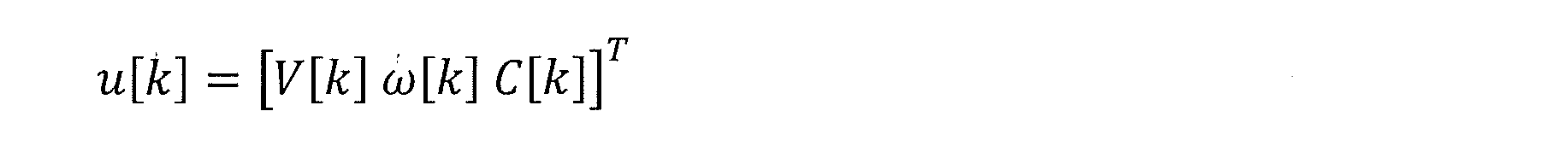
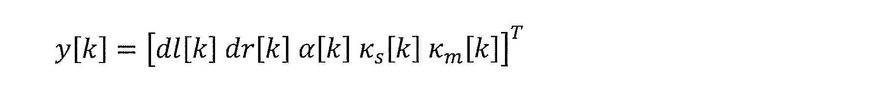
レーン推定部215では、下記数式2、数式3、数式4に示すように、出力y[k](観測値)としての左区画線位置dl、右区画線位置dr、ヨー角α、曲率κs、曲率κm、及び、入力u[k](制御入力値)としての車速V,ヨーレートω、曲率変化量Cを用いて、状態x[k](状態推定値)としての横位置z、ヨー角α、道幅D、及び曲率κを推定する。
ここで、x, u, yは、状態ベクトル(状態推定値)、入力ベクトル(制御入力値)、出力ベクトル(観測値)であり、Tは転置行列を表す記号である。
このとき、システムのダイナミクスを示す状態方程式は、数式5及び数式6で表現でき、状態ベクトルを用いて出力ベクトルを表した観測方程式は、数式7及び数式8で表現できる。
このとき、システムのダイナミクスを示す状態方程式は、数式5及び数式6で表現でき、状態ベクトルを用いて出力ベクトルを表した観測方程式は、数式7及び数式8で表現できる。


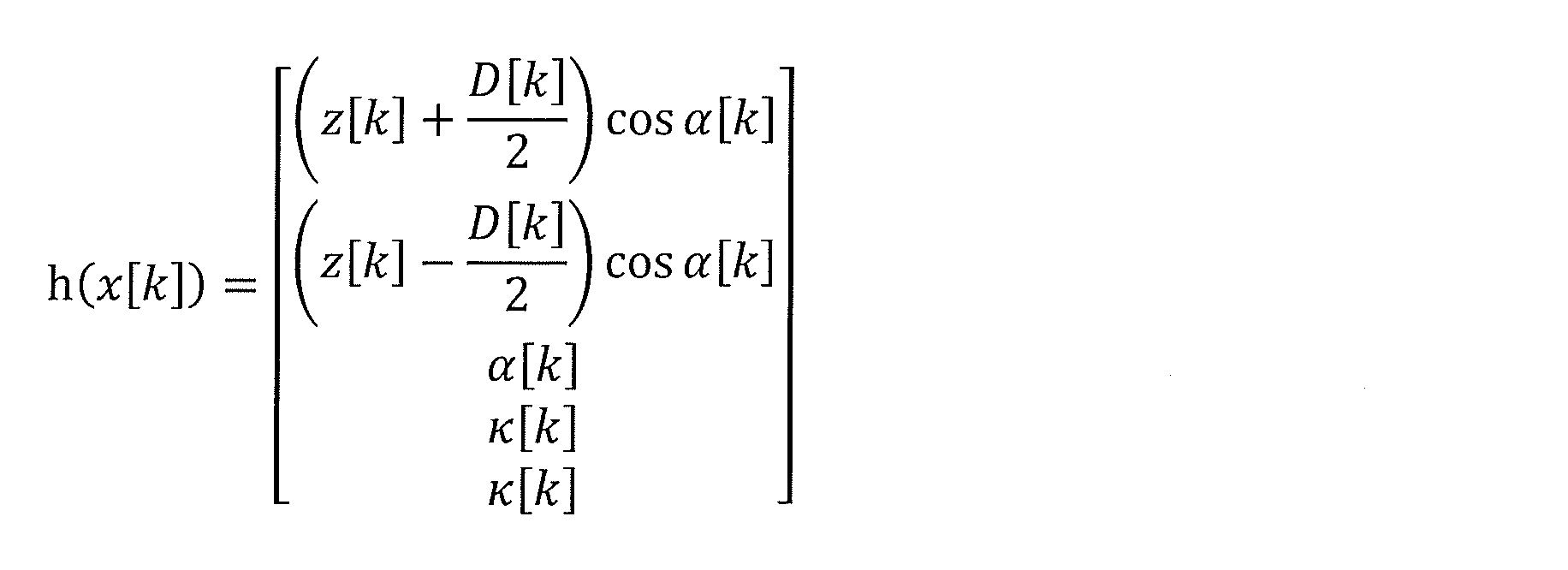
また、状態推定の確からしさを示す指標として、数式9に示す評価関数Jを設定する。

ここで、Tは現在のサンプリング、Hは評価区間長さ、換言すれば、評価関数Jに含めるサンプリング数、SQ,SR,SPは重み行列を表す。
また、曲折アクセント付きx^は、状態xの推定値(推定状態)であることを表し、曲折アクセント付きx^に「-」を上付き文字として付したものは、前回サンプリングにおける推定値であることを表している。
また、曲折アクセント付きx^は、状態xの推定値(推定状態)であることを表し、曲折アクセント付きx^に「-」を上付き文字として付したものは、前回サンプリングにおける推定値であることを表している。
上記の数式9で表すような評価関数Jを最適化計算に用い、評価関数Jの値を最小化するような状態推定値を求める手法は、Moving Horizon 推定(MHE)と呼ばれる手法である。
数式9の右辺の第1項は、各サンプリング間の状態推定値の変化量が数式6の状態方程式と一致するようにするための項であり、この項を最小化することによりシステムのダイナミクスに則した状態推定を行える。
数式9の右辺の第1項は、各サンプリング間の状態推定値の変化量が数式6の状態方程式と一致するようにするための項であり、この項を最小化することによりシステムのダイナミクスに則した状態推定を行える。
また、数式9の右辺の第2項は、各サンプリングの状態推定値と観測値との関係が、数式8の観測方程式と一致するようにするための項であり、この項を最小化することにより観測値に応じた状態推定を行える。
また、数式9の右辺の第3項は、前回サンプリングで得た状態推定値からの変化量を評価するための項であり、この項を最小化することにより評価区間長よりも以前の情報を推定に取り入れることができる。
また、数式9の右辺の第3項は、前回サンプリングで得た状態推定値からの変化量を評価するための項であり、この項を最小化することにより評価区間長よりも以前の情報を推定に取り入れることができる。
そして、数式9の右辺の各項が状態推定に与える影響度合いを、重み行列SQ,SR,SPによって決定する。
一般的なMoving Horizon 推定では、重み行列SQ,SRとして、システム雑音と観測雑音の共分散行列の逆行列を用い、また、重み行列SPとしては、数式5から数式8のシステムに拡張カルマンフィルタを適用した際に得た推定状態の誤差共分散行列の逆行列を用いる。
一般的なMoving Horizon 推定では、重み行列SQ,SRとして、システム雑音と観測雑音の共分散行列の逆行列を用い、また、重み行列SPとしては、数式5から数式8のシステムに拡張カルマンフィルタを適用した際に得た推定状態の誤差共分散行列の逆行列を用いる。
この場合、観測雑音が正規分布に従うことを仮定しているため、正規分布に従わずに真値に対して大きく外れた観測値(以下、外れ値と称する)が発生すると、外れ値が推定値に影響して、推定値が真値から大きく外れる可能性がある。
そこで、コントロールユニット21(レーン推定部215)は、観測値(換言すれば、測定値)である左区画線位置dl、右区画線位置dr、ヨー角α、曲率κs、曲率κmが外れ値である可能性が高い場合、その観測値の重みを小さくすることで、外れ値の影響を抑制した状態推定を行う。
そこで、コントロールユニット21(レーン推定部215)は、観測値(換言すれば、測定値)である左区画線位置dl、右区画線位置dr、ヨー角α、曲率κs、曲率κmが外れ値である可能性が高い場合、その観測値の重みを小さくすることで、外れ値の影響を抑制した状態推定を行う。
図5は、観測値、推定値、及び観測値の重みの相関を示す。
図5において、一点鎖線は、外れ値を考慮せずに状態推定を行ったときの推定値を示し、実線は、外れ値の重みを小さくして状態推定を行ったときの推定値を示す。更に、点線は真値を示し、丸印は測定値を示す。
この図5に示すように、外れ値を考慮せずに状態推定を行うと、外れ値の影響で推定値が真値から大きく外れる。一方、外れ値の重みを小さくすれば、外れ値の影響を抑止でき、推定値は真値に近い値となる。
図5において、一点鎖線は、外れ値を考慮せずに状態推定を行ったときの推定値を示し、実線は、外れ値の重みを小さくして状態推定を行ったときの推定値を示す。更に、点線は真値を示し、丸印は測定値を示す。
この図5に示すように、外れ値を考慮せずに状態推定を行うと、外れ値の影響で推定値が真値から大きく外れる。一方、外れ値の重みを小さくすれば、外れ値の影響を抑止でき、推定値は真値に近い値となる。
レーン推定部215は、数式9の右辺の第2項についての重み行列SRを、信頼度設定部214が算出した信頼度Wを用いて数式10に基づき算出する。

ここで、コントロールユニット21は、数式9の右辺の第1項に対する重み行列SQについても信頼度Wに応じて変更することができる。
但し、数式9の右辺各項の状態推定に対する影響度合いは各項の重みの比率によって決まるので、第1項に対する重みを小さくしかつ第2項に対する重みを小さくすると、結果的に重みを変更しない場合と大きく変わらない推定結果になる可能性がある。
但し、数式9の右辺各項の状態推定に対する影響度合いは各項の重みの比率によって決まるので、第1項に対する重みを小さくしかつ第2項に対する重みを小さくすると、結果的に重みを変更しない場合と大きく変わらない推定結果になる可能性がある。
そこで、コントロールユニット21は、数式9の右辺の第2項についての重み行列SRだけを、信頼度Wに応じて変更する。
なお、コントロールユニット21(信頼度設定部214)による信頼度Wの算出処理については、後で説明する。
なお、コントロールユニット21(信頼度設定部214)による信頼度Wの算出処理については、後で説明する。
図6は、図4のフローチャートのステップS505(レーン推定部215)における処理内容を示すフローチャートである。
まず、コントロールユニット21は、ステップS505Aにおいて、数式9の右辺各項の重み行列SQ,SR,SPを算出する。
まず、コントロールユニット21は、ステップS505Aにおいて、数式9の右辺各項の重み行列SQ,SR,SPを算出する。
ここで、コントロールユニット21は、数式9の右辺の第2項についての重み行列SRを、信頼度Wを用いて数式10に基づき算出する。
また、コントロールユニット21は、数式9の右辺の第1項についての重み行列SQをSQ=Q-1とし、更に、数式9の右辺の第3項についての重み行列SPを、数式5から数式8のシステムに拡張カルマンフィルタを適用した際に得た推定状態の誤差共分散行列の逆行列とする。
また、コントロールユニット21は、数式9の右辺の第1項についての重み行列SQをSQ=Q-1とし、更に、数式9の右辺の第3項についての重み行列SPを、数式5から数式8のシステムに拡張カルマンフィルタを適用した際に得た推定状態の誤差共分散行列の逆行列とする。
次いで、コントロールユニット21は、ステップS505Bに進み、数式9に示す評価関数Jの値を最小化するような状態xの推定値x^[k](k=T-H,…,T)を算出する、非線形計画問題を解く。
コントロールユニット21は、上記の非線形計画問題を解くために、公知の解法である逐次2次計画法や内点法などを用いることができ、逐次2次計画法を用いれば比較的高速に解を求めることができる。
コントロールユニット21は、上記の非線形計画問題を解くために、公知の解法である逐次2次計画法や内点法などを用いることができ、逐次2次計画法を用いれば比較的高速に解を求めることができる。
そして、コントロールユニット21は、ステップS505Cで、推定値x^[k](k=T-H,…,T)のうち、現在時刻の推定値x^[T]を出力する。
なお、コントロールユニット21は、推定値x^[k]の算出(レーン情報の推定)において、後述するような所定の制約条件を課することができる。
なお、コントロールユニット21は、推定値x^[k]の算出(レーン情報の推定)において、後述するような所定の制約条件を課することができる。
次に、信頼度Wに応じた重みの変更による効果を、簡単な数値例を用いて説明する。
以下では、信頼度Wに応じた重みの変更による効果を分かり易く説明するために、評価関数Jを、数式11に示した関数とする。

以下では、信頼度Wに応じた重みの変更による効果を分かり易く説明するために、評価関数Jを、数式11に示した関数とする。
数式11の評価関数Jにおいては、推定したい変数yに対し、2つの観測値、つまり、観測値=4、観測値=8を得ていることを示す。
ここで、数式11に示した評価関数Jの値を最小化することは、2つの観測値のどちらを信頼するかを係数wで重みづけして変数yを推定することと一致する。
ここで、数式11に示した評価関数Jの値を最小化することは、2つの観測値のどちらを信頼するかを係数wで重みづけして変数yを推定することと一致する。
ここで、観測値=8が外れ値であることが分かっていると仮定する。
図7は、重みづけ係数wをw=1として、数式11の右辺の各項に重みづけを行わない場合での評価関数Jの値を示す。
数式11の右辺の各項に重みづけを行わない場合、評価関数Jの値を最小化する変数yはy=6となり、外れ値である観測値=8の影響を大きく受けた推定結果となる。
図7は、重みづけ係数wをw=1として、数式11の右辺の各項に重みづけを行わない場合での評価関数Jの値を示す。
数式11の右辺の各項に重みづけを行わない場合、評価関数Jの値を最小化する変数yはy=6となり、外れ値である観測値=8の影響を大きく受けた推定結果となる。
図8は、外れ値の影響を小さくするために重みづけ係数wをw=0.01として重み付けを行った場合での評価関数Jの値を示す。
重みづけ係数wをw=0.01として重み付けを行った場合、つまり、外れ値である観測値=8の重みを小さくした場合、評価関数Jの値を最小化する変数yはy≒4となり、外れ値である観測値=8の影響を抑制した推定結果となる。
重みづけ係数wをw=0.01として重み付けを行った場合、つまり、外れ値である観測値=8の重みを小さくした場合、評価関数Jの値を最小化する変数yはy≒4となり、外れ値である観測値=8の影響を抑制した推定結果となる。
このように、外れ値の重みを小さくすることによって、外れ値が推定結果に及ぼす影響を抑制することができる。
なお、数式9の評価関数Jは、数式11の評価関数Jに比べて足し合わせる項が多く、また、2次形式になっていない項を含むため、数式11の評価関数Jに比べて複雑であるが、数式11の評価関数Jと同様に、外れ値の重みを小さくすることによって、外れ値が推定結果に及ぼす影響を抑制することができる。
なお、数式9の評価関数Jは、数式11の評価関数Jに比べて足し合わせる項が多く、また、2次形式になっていない項を含むため、数式11の評価関数Jに比べて複雑であるが、数式11の評価関数Jと同様に、外れ値の重みを小さくすることによって、外れ値が推定結果に及ぼす影響を抑制することができる。
コントロールユニット21は、上記のように、数式9の評価関数Jの値を最小化する最適化計算を行って状態推定値を求めるMoving Horizon 推定を実施するが、Moving Horizon 推定に代えて、数式5から数式8に示すシステムに対して公知の拡張カルマンフィルタを設計し、そこで用いる共分散行列Rを信頼度Wに応じて変更する構成とすることができる。
但し、Moving Horizon 推定では後述する制約条件を課することが可能であるが、拡張カルマンフィルタを用いる場合は制約条件を課することはできない。
但し、Moving Horizon 推定では後述する制約条件を課することが可能であるが、拡張カルマンフィルタを用いる場合は制約条件を課することはできない。
図9は、拡張カルマンフィルタにおける、前回サンプリングの推定結果を今回サンプリングの出力及び入力を用いて修正する逐次計算の様子を示す。
図10は、Moving Horizon 推定で、ある評価区間内(換言すれば、推定ホライズン内)の全ての入力(制御入力値)及び出力(観測値)を用いて推定値を算出する様子を示す。
図10は、Moving Horizon 推定で、ある評価区間内(換言すれば、推定ホライズン内)の全ての入力(制御入力値)及び出力(観測値)を用いて推定値を算出する様子を示す。
拡張カルマンフィルタでの逐次計算では、一度外れ値を推定に取り入れて推定誤差が生じた場合、時間をかけて逐次的に修正する必要がある。
これに対し、Moving Horizon 推定では、一度外れ値を推定に取り入れたとしても、次のサンプリング以降で外れ値の判定があれば、その影響を抑制できるため、修正が素早く行われる。
このため、コントロールユニット21は、拡張カルマンフィルタではなく、Moving Horizon 推定を採用している。
これに対し、Moving Horizon 推定では、一度外れ値を推定に取り入れたとしても、次のサンプリング以降で外れ値の判定があれば、その影響を抑制できるため、修正が素早く行われる。
このため、コントロールユニット21は、拡張カルマンフィルタではなく、Moving Horizon 推定を採用している。
コントロールユニット21は、前述した図6のフローチャートのステップS505Bで、数式9に示す評価関数Jの値を最小化するような推定値を算出する際に、推定値に制約条件を課することができる。
ここで、推定値の制約条件とは、評価関数Jを最小化するような推定値を算出する際に、推定値が満たす必要がある条件を、等式若しくは不等式で表したものである。
ここで、推定値の制約条件とは、評価関数Jを最小化するような推定値を算出する際に、推定値が満たす必要がある条件を、等式若しくは不等式で表したものである。
以下で、簡単な数値例を用いて上記の制約条件について説明する。
数式11の評価関数Jにおいて係数wを1としたとき、変数yに制約条件を課さない場合、評価関数Jを最小化する変数yは、図7に示したように変数y=6になる。
数式11の評価関数Jにおいて係数wを1としたとき、変数yに制約条件を課さない場合、評価関数Jを最小化する変数yは、図7に示したように変数y=6になる。
しかし、変数y≦4という制約条件を課した場合、変数yは4以下である必要があるため、変数y≦4という制約条件のもとで評価関数Jを最小化する変数yは4となる。
したがって、コントロールユニット21は、推定値に制約条件を課すことで、推定値がとりうる範囲を制限し、外れ値(観測値=8)が推定値に及ぼす影響を抑止することができる。
したがって、コントロールユニット21は、推定値に制約条件を課すことで、推定値がとりうる範囲を制限し、外れ値(観測値=8)が推定値に及ぼす影響を抑止することができる。
コントロールユニット21は、以下のような制約条件を推定値に加える。
例えば、車両10が幹線道路や高速道路などの整備された道路を走行する場合、走行経路の曲率κが急激に変化することはない。
そこで、コントロールユニット21は、曲率κの推定値κ^の変化量が一定値(Δκmax)以下となるように、曲率κの推定値κ^について数式12に示す制約条件を加える。

例えば、車両10が幹線道路や高速道路などの整備された道路を走行する場合、走行経路の曲率κが急激に変化することはない。
そこで、コントロールユニット21は、曲率κの推定値κ^の変化量が一定値(Δκmax)以下となるように、曲率κの推定値κ^について数式12に示す制約条件を加える。
数式12において、κ^-は前回サンプリングにおける曲率κの推定値である。
また、数式12のΔκmaxは、車両10の単位移動距離当たりでの曲率κの変化量の上限値であり、例えば、一般的な道路の曲率変化率の最大値に基づき設定される。
また、数式12のΔκmaxは、車両10の単位移動距離当たりでの曲率κの変化量の上限値であり、例えば、一般的な道路の曲率変化率の最大値に基づき設定される。
なお、コントロールユニット21は、Δκmaxの値を地図情報から取得した道路の曲率の変化量に基づき算出し、各サンプリングでΔκmaxの値を変更することができる。
コントロールユニット21は、曲率κの推定値κ^の変化量に上限を設ける制約条件を課すことで、例えば、実際値から大きくずれた曲率κの観測値を状態推定に用いたとしても、その影響で曲率κの推定値κ^が実際値から大きくずれることを抑止できる。
コントロールユニット21は、曲率κの推定値κ^の変化量に上限を設ける制約条件を課すことで、例えば、実際値から大きくずれた曲率κの観測値を状態推定に用いたとしても、その影響で曲率κの推定値κ^が実際値から大きくずれることを抑止できる。
また、車両10が走行車線に沿って走行している場合、車両10の横位置zが急激に変化することはない。
そこで、コントロールユニット21は、横位置zの推定値z^の変化量が一定値(Δzmax)以下となるように、横位置zの推定値z^について数式13に示す制約条件を加える。

そこで、コントロールユニット21は、横位置zの推定値z^の変化量が一定値(Δzmax)以下となるように、横位置zの推定値z^について数式13に示す制約条件を加える。
数式13において、z^-は前回サンプリングにおける推定値である。
また、数式13のΔzmaxは、単位時間当たりでの横位置zの変化量の上限値であり、例えば、一般的に車両10が走行車線に沿って走行している場合に発生し得る横位置zの変化量の最大値に基づく値である。
また、数式13のΔzmaxは、単位時間当たりでの横位置zの変化量の上限値であり、例えば、一般的に車両10が走行車線に沿って走行している場合に発生し得る横位置zの変化量の最大値に基づく値である。
また、横位置zの変化量は車速Vによって変化するため、コントロールユニット21は、車両10の車速Vに応じて上限値Δzmaxを変更することができる。
コントロールユニット21は、横位置zの推定値z^の変化量に上限を設ける制約条件を課すことで、例えば、実際値から大きくずれた左区画線位置dl及び/又は右区画線位置drの観測値を状態推定に用いたとしても、その影響で横位置zの推定値z^が実際値から大きくずれることを抑止することができる。
コントロールユニット21は、横位置zの推定値z^の変化量に上限を設ける制約条件を課すことで、例えば、実際値から大きくずれた左区画線位置dl及び/又は右区画線位置drの観測値を状態推定に用いたとしても、その影響で横位置zの推定値z^が実際値から大きくずれることを抑止することができる。
また、幹線道路や高速道路などの主要な道路の道幅は規格により定まっている。
そこで、コントロールユニット21は、道幅Dの推定値D^が所定範囲内となるように、道幅Dの推定値D^について数式14に示す制約条件を加える。

そこで、コントロールユニット21は、道幅Dの推定値D^が所定範囲内となるように、道幅Dの推定値D^について数式14に示す制約条件を加える。
数式14のDminは道幅Dの最小値(下限値)、Dmaxは道幅Dの最大値(上限値)である。例えば、道幅の規格に基づき、最小値Dmin=2.5m、最大値Dmax=4mとする。
コントロールユニット21は、道幅Dの推定値D^に下限及び上限を設ける制約条件を課すことで、例えば、区画線以外の白線の位置を測定した場合に、その影響で道幅Dの推定値が実際値から大きくずれることを抑止できる。
コントロールユニット21は、道幅Dの推定値D^に下限及び上限を設ける制約条件を課すことで、例えば、区画線以外の白線の位置を測定した場合に、その影響で道幅Dの推定値が実際値から大きくずれることを抑止できる。
次に、コントロールユニット21(信頼度設定部214)における信頼度Wの設定処理、つまり、図4のステップS504での処理内容を詳細に説明する。
コントロールユニット21は、各観測値(左右区画線位置dl,dr、ヨー角α、曲率κs、曲率κm)について、測定結果の確からしさ(正確性、正確度)を示す指標値である信頼度Wを設定する。
コントロールユニット21は、各観測値(左右区画線位置dl,dr、ヨー角α、曲率κs、曲率κm)について、測定結果の確からしさ(正確性、正確度)を示す指標値である信頼度Wを設定する。
信頼度Wは0から1までの値であり(0<W≦1)、信頼度Wの値が1に近いほど確からしさが高く、信頼度Wの値が0に近いほど確からしさが低いことを示す。
つまり、コントロールユニット21は、信頼度Wが1に近い観測値を状態推定に用いることで状態を正しく推定でき、信頼度Wが0に近い観測値(換言すれば、外れ値)を状態推定に用いることで状態推定に誤差が発生する可能性が高いことになる。
つまり、コントロールユニット21は、信頼度Wが1に近い観測値を状態推定に用いることで状態を正しく推定でき、信頼度Wが0に近い観測値(換言すれば、外れ値)を状態推定に用いることで状態推定に誤差が発生する可能性が高いことになる。
コントロールユニット21は、観測値yと、推定状態を用いて数式8の観測方程式から求めた推定値y^=h(x^)との誤差に基づいて、信頼度基礎値Wtmpを算出し、係る信頼度基礎値Wtmpを、観測値yのばらつき度合い、車両10の走行状態、車両10の周囲環境などに応じて補正して、最終的な信頼度Wを求める。
コントロールユニット21は、信頼度基礎値Wtmpを数式15にしたがって算出する。

数式15において、σは観測値yと推定値y^の誤差の標準偏差であり、σ2は観測値yと推定値y^の誤差の分散となる。
コントロールユニット21は、信頼度基礎値Wtmpを数式15にしたがって算出する。
図11は、観測値yと推定値y^との誤差と、信頼度基礎値Wtmpとの相関を示す。
観測値yと推定値y^との誤差が3σより小さい場合、誤差が十分に小さく、対象とする観測値yは十分信頼できるので、コントロールユニット21は、信頼度基礎値Wtmpを最大値である1に設定する。
観測値yと推定値y^との誤差が3σより小さい場合、誤差が十分に小さく、対象とする観測値yは十分信頼できるので、コントロールユニット21は、信頼度基礎値Wtmpを最大値である1に設定する。
一方、観測値yと推定値y^との誤差が3σより大きい場合、誤差が大きいほど観測値yの信頼性はより低いことになるので、コントロールユニット21は、誤差が大きくなるほど信頼度基礎値Wtmpを漸減させて、信頼度が低い観測値yが状態推定に与える影響を小さくする。
なお、数式15では3σを誤差の基準とするが、3σに限定するものではない。
コントロールユニット21は、誤差の小さい情報のみを用いて状態推定を実施したい場合、3σに代えて例えばσを信頼度基礎値Wtmpの算出に用い、逆に、誤差が比較的大きい情報も用いて状態推定したい場合、3σに代えて例えば5σを信頼度基礎値Wtmpの算出に用いることができる。
なお、数式15では3σを誤差の基準とするが、3σに限定するものではない。
コントロールユニット21は、誤差の小さい情報のみを用いて状態推定を実施したい場合、3σに代えて例えばσを信頼度基礎値Wtmpの算出に用い、逆に、誤差が比較的大きい情報も用いて状態推定したい場合、3σに代えて例えば5σを信頼度基礎値Wtmpの算出に用いることができる。
このように、コントロールユニット21が、観測値yと推定値y^との誤差に応じて信頼度基礎値Wtmpを設定することにより、誤差に応じた重みの設定が行われることになる。
しかし、誤差が小さい場合であっても観測値yが信頼できない場合がある。
また、誤差に応じた重みの設定では、一度推定に失敗して推定値y^が真値から大きくずれると、正しい値を測定したとしても重みが小さくなり、推定値y^の修正ができなくなる可能性がある。
しかし、誤差が小さい場合であっても観測値yが信頼できない場合がある。
また、誤差に応じた重みの設定では、一度推定に失敗して推定値y^が真値から大きくずれると、正しい値を測定したとしても重みが小さくなり、推定値y^の修正ができなくなる可能性がある。
そこで、コントロールユニット21は、信頼度基礎値Wtmpを、観測値のばらつき度合い、車両10の走行状態、車両10の周囲環境などに応じて補正して、最終的な信頼度Wを設定する。
図12は、信頼度基礎値Wtmpの補正パターンを示す。
コントロールユニット21は、観測値が十分信頼できると判断した場合は、図12中に一点鎖線で示すように、信頼度Wを1に固定する。これにより、観測値yと推定値y^の誤差によらず観測値に基づいたレーン推定が行われるようになる。
図12は、信頼度基礎値Wtmpの補正パターンを示す。
コントロールユニット21は、観測値が十分信頼できると判断した場合は、図12中に一点鎖線で示すように、信頼度Wを1に固定する。これにより、観測値yと推定値y^の誤差によらず観測値に基づいたレーン推定が行われるようになる。
また、コントロールユニット21は、観測値が信頼できないと判断した場合は、図12中に点線で示すように、信頼度Wが信頼度基礎値Wtmpより小さなるように補正する。
信頼度Wを信頼度基礎値Wtmpより小さく設定する方法としては、例えば、信頼度基礎値Wtmpの2乗値を信頼度Wとして設定する方法や、信頼度基礎値Wtmpに対して0から1の間の定数を乗算した値を信頼度Wとして設定する方法などがある。
信頼度Wを信頼度基礎値Wtmpより小さく設定する方法としては、例えば、信頼度基礎値Wtmpの2乗値を信頼度Wとして設定する方法や、信頼度基礎値Wtmpに対して0から1の間の定数を乗算した値を信頼度Wとして設定する方法などがある。
コントロールユニット21が信頼度基礎値Wtmpの2乗値を信頼度Wとして設定する場合、信頼度Wに対する誤差の影響を増幅することができる。
また、コントロールユニット21が信頼度基礎値Wtmpに対して定数を乗算した値を信頼度Wとして設定する場合、誤差によらず一定の割合で状態推定に与える影響を小さくすることができる。
また、コントロールユニット21が信頼度基礎値Wtmpに対して定数を乗算した値を信頼度Wとして設定する場合、誤差によらず一定の割合で状態推定に与える影響を小さくすることができる。
なお、コントロールユニット21は、信頼度Wを信頼度基礎値Wtmpより小さく設定する方法を、対象となる観測値や観測値が信頼できないと判断する条件などに応じて変更することができる。
また、コントロールユニット21は、観測値が十分信頼できるとの判断結果と、観測値が信頼できないとの判断結果との双方を得ていない場合、図12中に実線で示すように、信頼度Wを信頼度基礎値Wtmpと一致させる。
また、コントロールユニット21は、観測値が十分信頼できるとの判断結果と、観測値が信頼できないとの判断結果との双方を得ていない場合、図12中に実線で示すように、信頼度Wを信頼度基礎値Wtmpと一致させる。
以下では、信頼度Wの補正方法をより具体的に説明する。
図13は、外界認識センサ22を用いて測定した左右区画線位置dl、drの信頼度Wの補正条件、及び、補正結果としての信頼度Wを示す。
図13は、外界認識センサ22を用いて測定した左右区画線位置dl、drの信頼度Wの補正条件、及び、補正結果としての信頼度Wを示す。
ここで、左右区画線位置dl、drの信頼度Wを信頼度基礎値Wtmpよりも小さくする方法としては、信頼度基礎値Wtmpの2乗値を信頼度Wとする方法を用いる。
これは、信頼度Wに対する誤差の影響を増幅することで、左右区画線位置dl、drの測定結果が状態推定に及ぼす悪影響を抑制するためである。
これは、信頼度Wに対する誤差の影響を増幅することで、左右区画線位置dl、drの測定結果が状態推定に及ぼす悪影響を抑制するためである。
図13の条件[T-1-1]の車両10が交差点付近にいる場合、交差点内には区画線が存在しないため、外界認識センサ22は左右区画線位置dl、drを測定できず、左右区画線位置dl、drの測定結果の信頼性は低いことになる。
そこで、コントロールユニット21は、ナビゲーションシステム25からの情報に基づき、車両10と交差点との距離が一定値以下で車両10が交差点付近にいると判断した場合、左右区画線位置dl、drの信頼度Wを信頼度基礎値Wtmpの2乗値とする(W=Wtmp2<Wtmp)。
つまり、コントロールユニット21は、車両10が交差点付近にいる場合、図12に点線で示すように、左右区画線位置dl、drの信頼度Wを信頼度基礎値Wtmpよりも低い値に設定する。
そこで、コントロールユニット21は、ナビゲーションシステム25からの情報に基づき、車両10と交差点との距離が一定値以下で車両10が交差点付近にいると判断した場合、左右区画線位置dl、drの信頼度Wを信頼度基礎値Wtmpの2乗値とする(W=Wtmp2<Wtmp)。
つまり、コントロールユニット21は、車両10が交差点付近にいる場合、図12に点線で示すように、左右区画線位置dl、drの信頼度Wを信頼度基礎値Wtmpよりも低い値に設定する。
なお、コントロールユニット21が、信頼度Wを信頼度基礎値Wtmpから信頼度基礎値Wtmpの2乗値に急激に変化させると、推定値も急激に変化し、操舵制御の安定性を損ねる可能性がある。
そこで、コントロールユニット21は、信頼度Wを信頼度基礎値Wtmpと信頼度基礎値Wtmpの2乗値との間で徐々に変化させることができる。
そこで、コントロールユニット21は、信頼度Wを信頼度基礎値Wtmpと信頼度基礎値Wtmpの2乗値との間で徐々に変化させることができる。
図14は、信頼度Wを徐々に変化させる方法を説明するための図である。
コントロールユニット21は、信頼度Wを補正する条件についての閾値を2つ設定し、補正条件が第1閾値から第2閾値に達するまでの間で、信頼度Wを信頼度基礎値Wtmpから信頼度基礎値Wtmpの2乗値にまで徐々に変化させる。
コントロールユニット21は、信頼度Wを補正する条件についての閾値を2つ設定し、補正条件が第1閾値から第2閾値に達するまでの間で、信頼度Wを信頼度基礎値Wtmpから信頼度基礎値Wtmpの2乗値にまで徐々に変化させる。
例えば、条件[T-1-1]の場合、コントロールユニット21は、車両10と交差点との距離が第1閾値にまで減少した時点から信頼度Wを低下させ始める。
そして、コントロールユニット21は、車両10と交差点との距離が第1閾値よりも短い第2閾値に達したときに信頼度Wが信頼度基礎値Wtmpの2乗値に達するように、信頼度Wを信頼度基礎値Wtmpから信頼度基礎値Wtmpの2乗値にまで連続的に変化させる。
そして、コントロールユニット21は、車両10と交差点との距離が第1閾値よりも短い第2閾値に達したときに信頼度Wが信頼度基礎値Wtmpの2乗値に達するように、信頼度Wを信頼度基礎値Wtmpから信頼度基礎値Wtmpの2乗値にまで連続的に変化させる。
なお、コントロールユニット21は、例えば、3次関数などを用いた補間計算によって、信頼度Wを、信頼度基礎値Wtmpから信頼度基礎値Wtmpの2乗値にまで連続的に変化させることができる。
上記の信頼度Wの補正処理において、補正条件の成立に基づき信頼度Wが急変することを抑止するための処理は、以下で説明する交差点以外の条件、及び、左右区画線位置dl、dr以外の観測値についての信頼度Wの補正にも適用できることは明らかである。
上記の信頼度Wの補正処理において、補正条件の成立に基づき信頼度Wが急変することを抑止するための処理は、以下で説明する交差点以外の条件、及び、左右区画線位置dl、dr以外の観測値についての信頼度Wの補正にも適用できることは明らかである。
次に、図13の条件[T-1-2]の車両10の停止状態での左右区画線位置dl、drの信頼度Wの補正処理、換言すれば、左右区画線位置dl、drの信頼度Wを車速Vに応じて補正する処理を説明する。
車両10の走行車線内で停止している状況として、車両10が信号待ち等で交差点の停止線や直前で停車している場合や停車した先行車の後方に停車している場合などがある。
車両10の走行車線内で停止している状況として、車両10が信号待ち等で交差点の停止線や直前で停車している場合や停車した先行車の後方に停車している場合などがある。
車両10が交差点付近で停車している場合、交差点内は区画線が存在しないため、外界認識センサ22は、左右区画線位置dl、drを測定できない。
また、車両10が先行車の後方で停車している場合、先行車との車間距離が比較的短く、この場合、外界認識センサ22で認識可能な領域の一部を先行車が遮るため、外界認識センサ22は左右区画線位置dl、drを正しく測定できない可能性がある。
また、車両10が先行車の後方で停車している場合、先行車との車間距離が比較的短く、この場合、外界認識センサ22で認識可能な領域の一部を先行車が遮るため、外界認識センサ22は左右区画線位置dl、drを正しく測定できない可能性がある。
図15は、外界認識センサ22の認識可能領域を先行車が狭めた状態を示す図であり、外界認識センサ22から見て先行車の陰になる部分は、外界認識センサ22による測定が行えない領域になる。
そこで、コントロールユニット21は、車速Vが所定速度よりも低く車両10が停車していると判断した場合、左右区画線位置dl、drの信頼度Wを信頼度基礎値Wtmpの2乗値に設定する。
そこで、コントロールユニット21は、車速Vが所定速度よりも低く車両10が停車していると判断した場合、左右区画線位置dl、drの信頼度Wを信頼度基礎値Wtmpの2乗値に設定する。
次に、図13の条件[T-1-3]、つまり、左右区画線位置dl、drを正しく測定できていると推定できる場合での左右区画線位置dl、drの信頼度Wの設定を説明する。
観測値と推定値との誤差が大きい場合でも、コントロールユニット21は、左右区画線位置dl、drを正しく測定できている場合は信頼度Wを1として、左右区画線位置dl、drの観測値を状態推定に取り入れることで、推定値の修正を進めることができる。
そこで、コントロールユニット21は、左右区画線位置dl、dr、ヨー角α、曲率κsのそれぞれの測定ばらつきが全て小さく、かつ、測定した道幅D(換言すれば、左右区画線位置dl、drの絶対値の和)が一定範囲内である場合、左右区画線位置dl、drを正しく測定できていると推定して、左右区画線位置dl、drの信頼度Wを1に設定する。
観測値と推定値との誤差が大きい場合でも、コントロールユニット21は、左右区画線位置dl、drを正しく測定できている場合は信頼度Wを1として、左右区画線位置dl、drの観測値を状態推定に取り入れることで、推定値の修正を進めることができる。
そこで、コントロールユニット21は、左右区画線位置dl、dr、ヨー角α、曲率κsのそれぞれの測定ばらつきが全て小さく、かつ、測定した道幅D(換言すれば、左右区画線位置dl、drの絶対値の和)が一定範囲内である場合、左右区画線位置dl、drを正しく測定できていると推定して、左右区画線位置dl、drの信頼度Wを1に設定する。
なお、コントロールユニット21は、例えば、一定時間だけ過去までの観測値をメモリに保存して、保存した観測値を用いて分散を算出し、観測値の測定ばらつきの大きさを分散に基づき判断することができる。
また、コントロールユニット21は、観測値の時系列的に古いデータほど影響が減衰するような分散を逐次計算によって求めて、観測値の測定ばらつきの判定に用いることができる。
また、コントロールユニット21は、観測値の時系列的に古いデータほど影響が減衰するような分散を逐次計算によって求めて、観測値の測定ばらつきの判定に用いることができる。
ここで、外界認識センサ22による認識結果を用いてヨー角αと曲率κsを算出する際には、一般的に左右区画線位置dl、drの情報を用いるため、左右区画線位置dl、drが正しく測定できていなければ、ヨー角αと曲率κsを正しく算出できない。
換言すれば、ヨー角αと曲率κsが正しく算出できていない場合、左右区画線位置dl、drが正しく測定できていない可能性がある。
そこで、コントロールユニット21は、図13の条件[T-1-3]において、ヨー角αのばらつき度合い及び曲率κsのばらつき度合いを判定する。
換言すれば、ヨー角αと曲率κsが正しく算出できていない場合、左右区画線位置dl、drが正しく測定できていない可能性がある。
そこで、コントロールユニット21は、図13の条件[T-1-3]において、ヨー角αのばらつき度合い及び曲率κsのばらつき度合いを判定する。
更に、コントロールユニット21は、走行車線とは異なる区画線を誤って測定した結果を状態推定に用いないように、左右区画線位置dl、drの情報に基づき測定した道幅Dが一定範囲内の場合のみ、左右区画線位置dl、drは正しく測定できていると判断する。
ここで、道幅Dの一定範囲は、一般的な道路の道幅に基づく値であり、例えば、2.5m以上かつ4m以下の範囲とする。
ここで、道幅Dの一定範囲は、一般的な道路の道幅に基づく値であり、例えば、2.5m以上かつ4m以下の範囲とする。
次に、図13の条件[T-1-4]及び条件[T-1-5]において、左区画線位置dlの信頼度Wと右区画線位置drの信頼度Wを個別に設定する処理を説明する。
道路の状況などによっては左右の区画線を正しく測定できるとは限らず、左右の区画線の一方は正しく測定できて、他方は正しく測定できない場合が生じる。
道路の状況などによっては左右の区画線を正しく測定できるとは限らず、左右の区画線の一方は正しく測定できて、他方は正しく測定できない場合が生じる。
そこで、コントロールユニット21は、一方の区画線位置の測定ばらつきが小さい状態であって曲率κsの測定ばらつきも小さいときに、測定した道幅Dが一定範囲内であると、左右区画線位置のうち測定ばらつきのより小さい区画線位置、つまり、正しく測定できていると推定できる区画線位置の信頼度Wを1とし、他方の区画線位置の信頼度Wを信頼度基礎値Wtmpとする。
ここで、外界認識センサ22を用いてヨー角αを算出するためには、左右両方の区画線位置dl、drを正しく測定する必要があるため、図13の条件[T-1-4]及び[T-1-5]においてヨー角αのばらつき度合いを条件から除いてある。
ここで、外界認識センサ22を用いてヨー角αを算出するためには、左右両方の区画線位置dl、drを正しく測定する必要があるため、図13の条件[T-1-4]及び[T-1-5]においてヨー角αのばらつき度合いを条件から除いてある。
次に、図13の条件[T-1-6]の車両10と先行車との相対距離に応じた左右区画線位置dl、drの信頼度Wの設定処理を説明する。
図15に示したように、車両10と先行車との距離が短い場合、外界認識センサ22で認識可能な領域を先行車が遮るため、外界認識センサ22は左右区画線位置dl、drを正しく測定できない可能性がある。
そこで、コントロールユニット21は、外界認識センサ22を用いて認識した先行車との距離が一定値よりも短い場合、左右区画線位置dl、drの信頼度Wを信頼度基礎値Wtmpの2乗値に設定する。
図15に示したように、車両10と先行車との距離が短い場合、外界認識センサ22で認識可能な領域を先行車が遮るため、外界認識センサ22は左右区画線位置dl、drを正しく測定できない可能性がある。
そこで、コントロールユニット21は、外界認識センサ22を用いて認識した先行車との距離が一定値よりも短い場合、左右区画線位置dl、drの信頼度Wを信頼度基礎値Wtmpの2乗値に設定する。
次に、図13の条件[T-1-7]の左右区画線位置dl、drの測定ばらつきが大きいときの左右区画線位置dl、drの信頼度Wの補正処理を説明する。
左右区画線位置dl、drの測定ばらつきが大きい場合、レーン推定部215が、数式15に基づく信頼度基礎値Wtmpをレーン推定に用いたとしても、測定ばらつきの影響を十分に抑制できず、観測値と推定値との誤差が状態推定に悪影響を与える可能性がある。
左右区画線位置dl、drの測定ばらつきが大きい場合、レーン推定部215が、数式15に基づく信頼度基礎値Wtmpをレーン推定に用いたとしても、測定ばらつきの影響を十分に抑制できず、観測値と推定値との誤差が状態推定に悪影響を与える可能性がある。
そこで、コントロールユニット21は、左区画線位置dlの測定ばらつきが所定以上で、かつ、右区画線位置drの測定ばらつきも所定以上である場合、左区画線位置dl及び右区画線位置drの信頼度Wを信頼度基礎値Wtmpの2乗値に設定する。
なお、上記条件[T-1-3]-[T-1-5]、[T-1-7]における信頼度Wの補正処理は、観測値のばらつきに応じて、左区画線位置dl及び右区画線位置drの信頼度Wを補正する処理である。
なお、上記条件[T-1-3]-[T-1-5]、[T-1-7]における信頼度Wの補正処理は、観測値のばらつきに応じて、左区画線位置dl及び右区画線位置drの信頼度Wを補正する処理である。
コントロールユニット21は、図13の条件[T-1-1]-[T-1-7]のいずれにも該当しない場合、図13の条件[T-1-8]に該当すると判断して、左区画線位置dl及び右区画線位置drの信頼度Wを信頼度基礎値Wtmpに設定する。
コントロールユニット21は、図13の条件[T-1-1]-[T-1-8]毎に左右区画線位置dl、drの信頼度Wを補正することで、左右区画線位置dl、drを正しく測定できている場合には左右区画線位置dl、drの測定結果を状態推定(レーン推定)に取り入れることができ、正しく測定できていない場合には左右区画線位置dl、drの測定結果の影響を抑制した状態推定(レーン推定)が行える。
コントロールユニット21は、図13の条件[T-1-1]-[T-1-8]毎に左右区画線位置dl、drの信頼度Wを補正することで、左右区画線位置dl、drを正しく測定できている場合には左右区画線位置dl、drの測定結果を状態推定(レーン推定)に取り入れることができ、正しく測定できていない場合には左右区画線位置dl、drの測定結果の影響を抑制した状態推定(レーン推定)が行える。
図16は、外界認識センサ22を用いて測定したヨー角αの信頼度Wの補正条件、及び、補正結果としての信頼度Wを示す。
ここで、ヨー角αの信頼度Wを信頼度基礎値Wtmpよりも小さくする方法として、コントロールユニット21は、信頼度基礎値Wtmpに一定値(例えば10-3)を乗算した値を信頼度W(W=Wtmp×10-3)とする方法を採用する。
ここで、ヨー角αの信頼度Wを信頼度基礎値Wtmpよりも小さくする方法として、コントロールユニット21は、信頼度基礎値Wtmpに一定値(例えば10-3)を乗算した値を信頼度W(W=Wtmp×10-3)とする方法を採用する。
これは、コントロールユニット21が外界認識センサ22を用いてヨー角αを算出する場合、一般的に左右区画線位置dl、drの情報を用いて算出するため、誤差が小さくてもヨー角αの測定結果を信頼できない場合がある。
このため、コントロールユニット21が信頼度Wに対する誤差の影響を増幅しただけでは、ヨー角αの測定結果が推定値に与える悪影響を除去しきれないためである。
このため、コントロールユニット21が信頼度Wに対する誤差の影響を増幅しただけでは、ヨー角αの測定結果が推定値に与える悪影響を除去しきれないためである。
まず、図16の条件[T-2-1]の車両10が交差点付近にいる場合でのヨー角αの信頼度Wの補正処理を説明する。
交差点内には区画線が存在しないため、外界認識センサ22は左右区画線位置dl、drを測定できず、左右区画線位置dl、drの測定結果に基づくヨー角αの算出も行えなくなる。
そこで、コントロールユニット21は、ナビゲーションシステム25からの情報に基づき、車両10と交差点との距離が一定値以下で、車両10が交差点付近にいると判断した場合、ヨー角αの信頼度Wを、信頼度基礎値Wtmpに10-3を乗算した値とする(W=Wtmp×10-3)。
交差点内には区画線が存在しないため、外界認識センサ22は左右区画線位置dl、drを測定できず、左右区画線位置dl、drの測定結果に基づくヨー角αの算出も行えなくなる。
そこで、コントロールユニット21は、ナビゲーションシステム25からの情報に基づき、車両10と交差点との距離が一定値以下で、車両10が交差点付近にいると判断した場合、ヨー角αの信頼度Wを、信頼度基礎値Wtmpに10-3を乗算した値とする(W=Wtmp×10-3)。
次に、図16の条件[T-2-2]の車両10の停止状態でのヨー角αの信頼度Wの補正処理、換言すれば、車速Vに応じたヨー角αの信頼度Wの補正処理を説明する。
車両10の走行車線内で停止している状況として、車両10が信号待ち等で交差点の停止線や直前で停車している場合や停車した先行車の後方に停車している場合などがある。
車両10の走行車線内で停止している状況として、車両10が信号待ち等で交差点の停止線や直前で停車している場合や停車した先行車の後方に停車している場合などがある。
車両10が交差点付近で停車している場合、交差点内は区画線が存在しないため、外界認識センサ22は、左右区画線位置dl、drを測定できない。
また、車両10が先行車の後方で停車している場合、先行車との車間距離が比較的短く、この場合、図15に示したように、外界認識センサ22で認識可能な領域の一部を先行車が遮るため、外界認識センサ22は左右区画線位置dl、drを正しく測定できない可能性がある。
また、車両10が先行車の後方で停車している場合、先行車との車間距離が比較的短く、この場合、図15に示したように、外界認識センサ22で認識可能な領域の一部を先行車が遮るため、外界認識センサ22は左右区画線位置dl、drを正しく測定できない可能性がある。
つまり、車両10の停止状態では、左右区画線位置dl、drの測定精度が低下し、これに伴ってヨー角αの測定精度も低下することになる。
そこで、コントロールユニット21は、信頼度設定部214は、車速Vが所定車速よりも低く車両10が停車していると判断した場合、ヨー角αの信頼度Wを信頼度基礎値Wtmpに10-3を乗算した値とする。
そこで、コントロールユニット21は、信頼度設定部214は、車速Vが所定車速よりも低く車両10が停車していると判断した場合、ヨー角αの信頼度Wを信頼度基礎値Wtmpに10-3を乗算した値とする。
次に、図16の条件[T-2-3]、つまり、ヨー角αを正しく測定できていると推定できる場合でのヨー角αの信頼度Wの設定、換言すれば、観測値のばらつきに応じて信頼度Wを補正する処理を説明する。
コントロールユニット21は、観測値と推定値の誤差が大きい場合でも、ヨー角αを正しく測定できていると判断できる場合は、信頼度を1としてヨー角αの観測値を状態推定に取り入れることで、推定値の修正を進めることができる。
そこで、コントロールユニット21は、左右区画線位置dl、dr、ヨー角α、曲率κsのそれぞれの測定ばらつきが全て小さい場合、ヨー角αの信頼度Wを1に設定する。
コントロールユニット21は、観測値と推定値の誤差が大きい場合でも、ヨー角αを正しく測定できていると判断できる場合は、信頼度を1としてヨー角αの観測値を状態推定に取り入れることで、推定値の修正を進めることができる。
そこで、コントロールユニット21は、左右区画線位置dl、dr、ヨー角α、曲率κsのそれぞれの測定ばらつきが全て小さい場合、ヨー角αの信頼度Wを1に設定する。
ここで、コントロールユニット21が外界認識センサ22を用いてヨー角αを算出する際には、一般的に左右区画線位置dl、drの情報を用いるため、左右区画線位置dl、drの双方が正しく測定できていなければ、ヨー角αも正しく算出できない。
このため、図16の条件[T-2-3]は、左右区画線位置dl、drのばらつき度合いを判定条件に含む。
また、コントロールユニット21は、曲率κsを左右区画線位置dl、drの情報に基づいて算出するから、曲率κsの測定結果がばらついている場合は、ヨー角αも正しく算出できていない可能性があるため、図16の条件[T-2-3]は、曲率κsのばらつき度合いも判定条件に含む。
このため、図16の条件[T-2-3]は、左右区画線位置dl、drのばらつき度合いを判定条件に含む。
また、コントロールユニット21は、曲率κsを左右区画線位置dl、drの情報に基づいて算出するから、曲率κsの測定結果がばらついている場合は、ヨー角αも正しく算出できていない可能性があるため、図16の条件[T-2-3]は、曲率κsのばらつき度合いも判定条件に含む。
次に、図16の条件[T-2-4]の車両10と先行車との相対距離に応じたヨー角αの信頼度Wの設定処理を説明する。
図15に示したように、車両10と先行車との距離が短い場合、外界認識センサ22で認識可能な領域を先行車が遮るため、外界認識センサ22は左右区画線位置dl、drを正しく測定できない可能性があり、左右区画線位置dl、drを正しく測定できないと、ヨー角αの測定精度も低下する。
そこで、コントロールユニット21は、外界認識センサ22が認識した先行車との距離が一定値よりも短い場合、ヨー角αの信頼度Wを信頼度基礎値Wtmpに10-3を乗算した値とする。
図15に示したように、車両10と先行車との距離が短い場合、外界認識センサ22で認識可能な領域を先行車が遮るため、外界認識センサ22は左右区画線位置dl、drを正しく測定できない可能性があり、左右区画線位置dl、drを正しく測定できないと、ヨー角αの測定精度も低下する。
そこで、コントロールユニット21は、外界認識センサ22が認識した先行車との距離が一定値よりも短い場合、ヨー角αの信頼度Wを信頼度基礎値Wtmpに10-3を乗算した値とする。
次に、図16の条件[T-2-5]の左右区画線位置dl、drの測定ばらつきが大きい場合におけるヨー角αの信頼度Wの設定処理を説明する。
ここで、コントロールユニット21が外界認識センサ22を用いてヨー角αを算出する際には、一般的に左右区画線位置dl、drの情報を用いるため、左右区画線位置dl、drのうちのいずれか一方でもばらつきが大きい場合、コントロールユニット21は、ヨー角αを正しく算出できない。
そこで、コントロールユニット21は、左右区画線位置dl、drのうちのいずれか一方でもばらつきが大きい場合、ヨー角αの信頼度Wを信頼度基礎値Wtmpに10-3を乗算した値とする。
ここで、コントロールユニット21が外界認識センサ22を用いてヨー角αを算出する際には、一般的に左右区画線位置dl、drの情報を用いるため、左右区画線位置dl、drのうちのいずれか一方でもばらつきが大きい場合、コントロールユニット21は、ヨー角αを正しく算出できない。
そこで、コントロールユニット21は、左右区画線位置dl、drのうちのいずれか一方でもばらつきが大きい場合、ヨー角αの信頼度Wを信頼度基礎値Wtmpに10-3を乗算した値とする。
なお、コントロールユニット21は、条件[T-2-1]-[T-2-5]のいずれにも該当しない場合、図16の条件[T-2-6]に該当すると判断して、ヨー角αの信頼度Wを信頼度基礎値Wtmpとする。
コントロールユニット21は、図16に示した条件[T-2-1]-[T-2-6]毎にヨー角αの信頼度Wを補正することで、ヨー角αを正しく測定できている場合にはヨー角αの測定結果を状態推定(レーン推定)に取り入れることができ、正しく測定できていない場合にはヨー角αの測定結果の影響を抑制した状態推定(レーン推定)が行える。
コントロールユニット21は、図16に示した条件[T-2-1]-[T-2-6]毎にヨー角αの信頼度Wを補正することで、ヨー角αを正しく測定できている場合にはヨー角αの測定結果を状態推定(レーン推定)に取り入れることができ、正しく測定できていない場合にはヨー角αの測定結果の影響を抑制した状態推定(レーン推定)が行える。
図17は、外界認識センサ22を用いて測定した曲率κsの信頼度Wの補正条件、及び、補正結果としての信頼度Wを示す。
ここで、コントロールユニット21は、曲率κsの信頼度Wを信頼度基礎値Wtmpよりも小さくする方法として、信頼度基礎値Wtmpに一定値(例えば10-3)を乗算した値を信頼度W(W=Wtmp×10-3)とする方法を採用する。
ここで、コントロールユニット21は、曲率κsの信頼度Wを信頼度基礎値Wtmpよりも小さくする方法として、信頼度基礎値Wtmpに一定値(例えば10-3)を乗算した値を信頼度W(W=Wtmp×10-3)とする方法を採用する。
これは、コントロールユニット21が外界認識センサ22を用いて曲率κsを算出する場合、一般的に左右区画線位置dl、drの情報を用いて算出するため、誤差が小さくても曲率κsの測定結果を信頼できない場合がある。
このため、コントロールユニット21が信頼度Wに対する誤差の影響を増幅しただけでは、曲率κsの測定結果が推定値に与える悪影響を除去しきれないためである。
このため、コントロールユニット21が信頼度Wに対する誤差の影響を増幅しただけでは、曲率κsの測定結果が推定値に与える悪影響を除去しきれないためである。
まず、図17の条件[T-3-1]の測定限界に基づく曲率κsの信頼度Wの補正処理を説明する。
コントロールユニット21は、曲率κsを、外界認識センサ22を用いて測定した左右区画線位置dl、drの情報に基づき算出する。
コントロールユニット21は、曲率κsを、外界認識センサ22を用いて測定した左右区画線位置dl、drの情報に基づき算出する。
しかし、外界認識センサ22で測定可能な領域(認識範囲)は限界があるため、外界認識センサ22を用いた曲率κsの測定においては、一定以上の大きな曲率κsを測定することはできない。
そこで、コントロールユニット21は、外界認識センサ22を用いて測定した曲率κsが、外界認識センサ22の測定可能領域に基づき予め設定した上限値を超えている場合、曲率κsの信頼度Wを、信頼度基礎値Wtmpに10-3を乗算した値とする。
そこで、コントロールユニット21は、外界認識センサ22を用いて測定した曲率κsが、外界認識センサ22の測定可能領域に基づき予め設定した上限値を超えている場合、曲率κsの信頼度Wを、信頼度基礎値Wtmpに10-3を乗算した値とする。
次に、図17の条件[T-3-2]の車両10が交差点付近にいる場合での曲率κsの信頼度Wの補正処理を説明する。
交差点内には区画線が存在しないため、車両10が交差点付近にいる場合、外界認識センサ22は左右区画線位置dl、drを測定できず、左右区画線位置dl、drに基づく曲率κsの算出は不能になる。
交差点内には区画線が存在しないため、車両10が交差点付近にいる場合、外界認識センサ22は左右区画線位置dl、drを測定できず、左右区画線位置dl、drに基づく曲率κsの算出は不能になる。
そこで、コントロールユニット21は、ナビゲーションシステム25からの情報に基づき、車両10と交差点との距離が一定値以下で車両10が交差点付近にいると判断した場合、外界認識センサ22を用いて測定した曲率κsの信頼度Wを、信頼度基礎値Wtmpに10-3を乗算した値とする。
次に、図17の条件[T-3-3]の車両10の停止状態での曲率κsの信頼度Wの補正処理、換言すれば、車速Vに応じた曲率κsの信頼度Wの補正処理を説明する。
車両10の走行車線内で停止している状況として、車両10が信号待ち等で交差点の停止線や直前で停車している場合や停車した先行車の後方に停車している場合などがある。
車両10の走行車線内で停止している状況として、車両10が信号待ち等で交差点の停止線や直前で停車している場合や停車した先行車の後方に停車している場合などがある。
車両10が交差点付近で停車している場合、交差点内は区画線が存在しないため、外界認識センサ22は、左右区画線位置dl、drを測定できない。
また、車両10が先行車の後方で停車している場合、先行車との車間距離が比較的短く、この場合、図15に示したように、外界認識センサ22で認識可能な領域の一部を先行車が遮るため、外界認識センサ22は左右区画線位置dl、drを正しく測定できない可能性がある。
また、車両10が先行車の後方で停車している場合、先行車との車間距離が比較的短く、この場合、図15に示したように、外界認識センサ22で認識可能な領域の一部を先行車が遮るため、外界認識センサ22は左右区画線位置dl、drを正しく測定できない可能性がある。
つまり、車両10の停止状態では、左右区画線位置dl、drの測定精度が低下し、これに伴って曲率κsの測定精度も低下することになる。
そこで、コントロールユニット21は、車速Vが十分小さく車両10が停車していると判断した場合、外界認識センサ22を用いて測定した曲率κsの信頼度Wを、信頼度基礎値Wtmpに10-3を乗算した値とする。
そこで、コントロールユニット21は、車速Vが十分小さく車両10が停車していると判断した場合、外界認識センサ22を用いて測定した曲率κsの信頼度Wを、信頼度基礎値Wtmpに10-3を乗算した値とする。
次に、図17の条件[T-3-4]の車両10と先行車との相対距離に応じた曲率κsの信頼度Wの補正処理を説明する。
図15に示したように、車両10と先行車との距離が短い場合、外界認識センサ22で認識可能な領域を先行車が遮るため、外界認識センサ22は左右区画線位置dl、drを正しく測定できない可能性があり、左右区画線位置dl、drを正しく測定できないと、曲率κsの測定精度も低下する。
そこで、コントロールユニット21は、外界認識センサ22で認識した先行車との距離が一定値よりも短い場合、曲率κsの信頼度Wを信頼度基礎値Wtmpに10-3を乗算した値とする。
図15に示したように、車両10と先行車との距離が短い場合、外界認識センサ22で認識可能な領域を先行車が遮るため、外界認識センサ22は左右区画線位置dl、drを正しく測定できない可能性があり、左右区画線位置dl、drを正しく測定できないと、曲率κsの測定精度も低下する。
そこで、コントロールユニット21は、外界認識センサ22で認識した先行車との距離が一定値よりも短い場合、曲率κsの信頼度Wを信頼度基礎値Wtmpに10-3を乗算した値とする。
次に、図17の条件[T-3-5]の左右区画線位置dl、drの測定ばらつきに応じた曲率κsの信頼度Wの補正処理を説明する。
ここで、コントロールユニット21が外界認識センサ22を用いて曲率κsを算出する際には、一般的に外界認識センサ22を用いて測定した左右区画線位置dl、drの両方若しくはいずれか一方を用いるため、左右区画線位置dl、dr双方の測定ばらつきが大きい場合は、コントロールユニット21は、曲率κsを正しく測定できない。
そこで、コントロールユニット21は、左右区画線位置dl、dr双方の測定ばらつきが大きい場合、曲率κsの信頼度Wを信頼度基礎値Wtmpに10-3を乗算した値とする。
ここで、コントロールユニット21が外界認識センサ22を用いて曲率κsを算出する際には、一般的に外界認識センサ22を用いて測定した左右区画線位置dl、drの両方若しくはいずれか一方を用いるため、左右区画線位置dl、dr双方の測定ばらつきが大きい場合は、コントロールユニット21は、曲率κsを正しく測定できない。
そこで、コントロールユニット21は、左右区画線位置dl、dr双方の測定ばらつきが大きい場合、曲率κsの信頼度Wを信頼度基礎値Wtmpに10-3を乗算した値とする。
次に、図17の条件[T-3-6]の曲率κsの確からしさに基づく曲率κsの信頼度Wの補正処理を説明する。
コントロールユニット21は、外界認識センサ22を用いて曲率κsを測定するとともに、ナビゲーションシステム25によって得た車両10が走行している道路の形状(地図情報)に基づき曲率κmを測定する。
コントロールユニット21は、外界認識センサ22を用いて曲率κsを測定するとともに、ナビゲーションシステム25によって得た車両10が走行している道路の形状(地図情報)に基づき曲率κmを測定する。
また、コントロールユニット21は、車両10の走行軌跡の曲率κdを車両挙動に基づいて算出することができ、車両10が区画線に沿って走行している場合、外界認識センサ22やナビゲーションシステム25を用いて測定した走行経路の曲率κs,κmと、車両挙動に基づく走行軌跡の曲率κdとの差は十分に小さくなる。
そこで、コントロールユニット21は、外界認識センサ22を用いて算出した曲率κsと、地図情報から取得した曲率κmと、車両10の挙動から算出した曲率κdとを比較し、外界認識センサ22を用いて算出した曲率κsの確からしさが低いと判定した場合、外界認識センサ22を用いて算出した曲率κsの信頼度Wを信頼度基礎値Wtmpに10-3を乗算した値とする。
なお、曲率κsの確からしさの判定方法については、後で詳細に説明する。
そこで、コントロールユニット21は、外界認識センサ22を用いて算出した曲率κsと、地図情報から取得した曲率κmと、車両10の挙動から算出した曲率κdとを比較し、外界認識センサ22を用いて算出した曲率κsの確からしさが低いと判定した場合、外界認識センサ22を用いて算出した曲率κsの信頼度Wを信頼度基礎値Wtmpに10-3を乗算した値とする。
なお、曲率κsの確からしさの判定方法については、後で詳細に説明する。
コントロールユニット21は、上記の条件[T-3-1]-[T-3-6]のいずれにも該当しない場合、図17の条件[T-3-7]に該当すると判断して、外界認識センサ22を用いて算出した曲率κsの信頼度Wを信頼度基礎値Wtmpとする。
コントロールユニット21は、図17に示した条件[T-3-1]-[T-3-7]毎に曲率κsの信頼度Wを補正することで、曲率κsが正しく測定できている場合には曲率κsの測定結果を状態推定(レーン推定)に取り入れることができ、正しく測定できていない場合には曲率κsの測定結果の影響を抑制した状態推定(レーン推定)が行える。
コントロールユニット21は、図17に示した条件[T-3-1]-[T-3-7]毎に曲率κsの信頼度Wを補正することで、曲率κsが正しく測定できている場合には曲率κsの測定結果を状態推定(レーン推定)に取り入れることができ、正しく測定できていない場合には曲率κsの測定結果の影響を抑制した状態推定(レーン推定)が行える。
図18は、地図情報から取得した曲率κmの信頼度Wの補正条件、及び、補正結果としての信頼度Wを示す。
ここで、コントロールユニット21は、地図情報から取得した曲率κmの信頼度Wを小さくする方法として、信頼度基礎値Wtmpに一定値(例えば10-3)を乗算した値を信頼度W(W=Wtmp×10-3)とする方法を採用する。
ここで、コントロールユニット21は、地図情報から取得した曲率κmの信頼度Wを小さくする方法として、信頼度基礎値Wtmpに一定値(例えば10-3)を乗算した値を信頼度W(W=Wtmp×10-3)とする方法を採用する。
地図情報から取得した曲率κmの誤差としては、GPSを用いた測位誤差によって生じる誤差や、複数のノード点から曲率κmを算出する際に生じる誤差、地図情報そのものが持っている誤差などがある。
しかし、コントロールユニット21は、これら誤差の存在の有無を、地図情報から取得した曲率κmと推定値との比較からは判別できず、信頼度Wに対する誤差の影響を増幅しただけでは観測値が推定値に与える悪影響を除去しきれないためである。
しかし、コントロールユニット21は、これら誤差の存在の有無を、地図情報から取得した曲率κmと推定値との比較からは判別できず、信頼度Wに対する誤差の影響を増幅しただけでは観測値が推定値に与える悪影響を除去しきれないためである。
まず、図18の条件[T-4-1]の測定限界に基づく曲率κmの信頼度Wの補正処理を説明する。
コントロールユニット21がレーン推定を正しく行うためには走行経路の曲率κの情報が必要であり、外界認識センサ22を用いて算出した曲率κsが明らかに間違っている場合、コントロールユニット21は、レーン推定に地図情報から取得した曲率κmを用いる必要がある。
コントロールユニット21がレーン推定を正しく行うためには走行経路の曲率κの情報が必要であり、外界認識センサ22を用いて算出した曲率κsが明らかに間違っている場合、コントロールユニット21は、レーン推定に地図情報から取得した曲率κmを用いる必要がある。
そこで、コントロールユニット21は、外界認識センサ22を用いて算出した曲率κsが測定限界を超えていて、かつ、曲率κsと車両10の挙動から算出した走行軌跡の曲率κdとの差が一定以上に大きく、曲率κsが誤っている可能性が高い場合、誤差がなければ地図情報から取得した曲率κmに基づきレーン推定が行われるように、地図情報から取得した曲率κmの信頼度Wを信頼度基礎値Wtmpとする。
次に、図18の条件[T-4-2]の地図情報から取得した曲率κmの確からしさに基づく曲率κmの信頼度Wの補正処理を説明する。
コントロールユニット21は、走行経路の曲率κとして、地図情報に基づく曲率κmとともに、外界認識センサ22を用いて曲率κsを求める。また、コントロールユニット21は、車両10の走行軌跡の曲率κdを車両挙動に基づき算出することができる。
コントロールユニット21は、走行経路の曲率κとして、地図情報に基づく曲率κmとともに、外界認識センサ22を用いて曲率κsを求める。また、コントロールユニット21は、車両10の走行軌跡の曲率κdを車両挙動に基づき算出することができる。
そして、車両10が区画線に沿って走行している場合、走行経路の曲率κm,κsと走行軌跡の曲率κdの差は十分に小さくなる。
そこで、コントロールユニット21は、外界認識センサ22を用いて算出した曲率κs、地図情報から取得した曲率κm、車両10の挙動に基づき算出した曲率κdを比較し、地図情報から取得した曲率κmの確からしさが低いと判断した場合、地図情報から取得した曲率κmの信頼度Wを信頼度基礎値Wtmpに10-3を乗算した値とする。
なお、曲率κmの確からしさの判定方法については、後で詳細に説明する。
そこで、コントロールユニット21は、外界認識センサ22を用いて算出した曲率κs、地図情報から取得した曲率κm、車両10の挙動に基づき算出した曲率κdを比較し、地図情報から取得した曲率κmの確からしさが低いと判断した場合、地図情報から取得した曲率κmの信頼度Wを信頼度基礎値Wtmpに10-3を乗算した値とする。
なお、曲率κmの確からしさの判定方法については、後で詳細に説明する。
コントロールユニット21は、上記の条件[T-4-1]-[T-4-2]のいずれにも該当しない場合、図18の条件[T-4-3]に該当すると判断して、地図情報から取得した曲率κmの信頼度Wを信頼度基礎値Wtmpとする。
コントロールユニット21は、図18に示した条件[T-4-1]-[T-4-3]毎に曲率κmの信頼度Wを補正することで、曲率κmが正しく測定できている場合には曲率κmの測定結果を状態推定(レーン推定)に取り入れることができ、正しく測定できていない場合には曲率κmの測定結果の影響を抑制した状態推定(レーン推定)が行える。
コントロールユニット21は、図18に示した条件[T-4-1]-[T-4-3]毎に曲率κmの信頼度Wを補正することで、曲率κmが正しく測定できている場合には曲率κmの測定結果を状態推定(レーン推定)に取り入れることができ、正しく測定できていない場合には曲率κmの測定結果の影響を抑制した状態推定(レーン推定)が行える。
以下では、曲率κs,κmについて信頼度Wの補正に用いる確からしさの判定方法を説明する。
コントロールユニット21は、曲率κs,κmの確からしさを、外界認識センサ22を用いて算出した曲率κs、地図情報から取得した曲率κm、車両10の挙動から算出した走行軌跡の曲率κdを比較することで判定する。
なお、コントロールユニット21は、走行軌跡の曲率κdを、数式16にしたがって算出する。
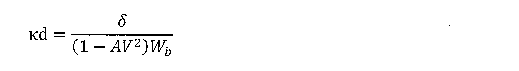
数式16において、δは操舵角、Aはスタビリティファクタ、Wbはホイールベース、Vは車速である。
コントロールユニット21は、曲率κs,κmの確からしさを、外界認識センサ22を用いて算出した曲率κs、地図情報から取得した曲率κm、車両10の挙動から算出した走行軌跡の曲率κdを比較することで判定する。
なお、コントロールユニット21は、走行軌跡の曲率κdを、数式16にしたがって算出する。
図19のフローチャートは、外界認識センサ22を用いて測定した曲率κsの信頼度Wの補正(つまり、図17の条件[T-3-6])に用いる、曲率κsの確からしさJDGκsの算出手順を示す。
ここで、コントロールユニット21は、曲率κsの確からしさが高いと判断したときにJDGκsを1に設定し、曲率κsの確からしさが低いと判断したときにJDGκsを0に設定する。
ここで、コントロールユニット21は、曲率κsの確からしさが高いと判断したときにJDGκsを1に設定し、曲率κsの確からしさが低いと判断したときにJDGκsを0に設定する。
コントロールユニット21は、ステップS601で、曲率κsの確からしさJDGκsの前回値が1であるか否かを判断する。
そして、コントロールユニット21は、曲率κsの確からしさJDGκsの前回値が1であればステップS602に進み、曲率κsの確からしさJDGκsの前回値が1でない場合(換言すれば、曲率κsの確からしさJDGκsの前回値が0である場合)はステップS605に進む。
そして、コントロールユニット21は、曲率κsの確からしさJDGκsの前回値が1であればステップS602に進み、曲率κsの確からしさJDGκsの前回値が1でない場合(換言すれば、曲率κsの確からしさJDGκsの前回値が0である場合)はステップS605に進む。
コントロールユニット21は、ステップS602で、曲率κsと曲率κdとの差分の絶対値が閾値Th1より大きく、かつ、曲率κsと曲率κdとの差分の絶対値が曲率κmと曲率κdとの差分の絶対値よりも大きい、という第1判定条件が成立しているか否かを判断する。
前記第1判定条件が成立している場合、つまり、外界認識センサ22を用いて算出した曲率κsが走行軌跡の曲率κdから大きくずれていて、かつ、そのずれ量が、地図情報から取得した曲率κmの走行軌跡の曲率κdに対するずれ量よりも大きい場合は、曲率κsの確からしさが低い状態(換言すれば、曲率κsが正しく測定できていないと推定できる状態)である。
前記第1判定条件が成立している場合、つまり、外界認識センサ22を用いて算出した曲率κsが走行軌跡の曲率κdから大きくずれていて、かつ、そのずれ量が、地図情報から取得した曲率κmの走行軌跡の曲率κdに対するずれ量よりも大きい場合は、曲率κsの確からしさが低い状態(換言すれば、曲率κsが正しく測定できていないと推定できる状態)である。
そこで、コントロールユニット21は、前記第1判定条件が成立している場合、ステップS603に進み、曲率κsの確からしさJDGκsを0に設定する。
一方、前記第1判定条件が成立していない場合、曲率κsの確からしさが高い状態(換言すれば、曲率κsが正しく測定できていると推定できる状態)であるので、コントロールユニット21は、ステップS604に進み、曲率κsの確からしさJDGκsを1に保持する。
一方、前記第1判定条件が成立していない場合、曲率κsの確からしさが高い状態(換言すれば、曲率κsが正しく測定できていると推定できる状態)であるので、コントロールユニット21は、ステップS604に進み、曲率κsの確からしさJDGκsを1に保持する。
また、コントロールユニット21は、ステップS601で曲率κsの確からしさJDGκsの前回値が1でないと判断してステップS605に進むと、曲率κsと曲率κdとの差分の絶対値が閾値Th1より小さい、という第2判定条件が成立しているか否かを判断する。
前記第2判定条件が成立している場合、つまり、外界認識センサ22を用いて算出した曲率κsと走行軌跡の曲率κdとのずれ量が一定値未満である場合、外界認識センサ22を用いて算出した曲率κsの確からしさは高い状態である。
前記第2判定条件が成立している場合、つまり、外界認識センサ22を用いて算出した曲率κsと走行軌跡の曲率κdとのずれ量が一定値未満である場合、外界認識センサ22を用いて算出した曲率κsの確からしさは高い状態である。
そこで、コントロールユニット21は、前記第2判定条件が成立している場合、ステップS606に進み、曲率κsの確からしさJDGκsを1に設定する。
一方、前記第2判定条件が成立していない場合、つまり、外界認識センサ22を用いて算出した曲率κsと走行軌跡の曲率κdとのずれ量が一定値以上である場合、曲率κsの確からしさが低い状態であるので、コントロールユニット21は、ステップS607に進み、曲率κsの確からしさJDGκsを0に保持する。
一方、前記第2判定条件が成立していない場合、つまり、外界認識センサ22を用いて算出した曲率κsと走行軌跡の曲率κdとのずれ量が一定値以上である場合、曲率κsの確からしさが低い状態であるので、コントロールユニット21は、ステップS607に進み、曲率κsの確からしさJDGκsを0に保持する。
コントロールユニット21は、上記のようにして曲率κsの確からしさJDGκsを設定し、確からしさJDGκsに基づき図17の条件[T-3-6]を満たすか否かを判断する。
つまり、コントロールユニット21は、確からしさJDGκsが0であれば、曲率κsの確からしさが低いと判断して、外界認識センサ22を用いて算出した曲率κsの信頼度Wを信頼度基礎値Wtmpに10-3を乗算した値とする。
つまり、コントロールユニット21は、確からしさJDGκsが0であれば、曲率κsの確からしさが低いと判断して、外界認識センサ22を用いて算出した曲率κsの信頼度Wを信頼度基礎値Wtmpに10-3を乗算した値とする。
図20のフローチャートは、地図情報から取得した曲率κmの信頼度Wの補正(図18の条件[T-4-2])に用いる、曲率κmの確からしさJDGκmの算出手順を示す。
ここで、コントロールユニット21は、曲率κmの確からしさが高いと判断したときにJDGκmを1に設定し、曲率κmの確からしさが低いと判断したときにJDGκmを0に設定する。
ここで、コントロールユニット21は、曲率κmの確からしさが高いと判断したときにJDGκmを1に設定し、曲率κmの確からしさが低いと判断したときにJDGκmを0に設定する。
コントロールユニット21は、ステップS701で、曲率κmの確からしさJDGκmの前回値が1であるか否かを判断する。
そして、コントロールユニット21は、曲率κmの確からしさJDGκmの前回値が1であればステップS702に進み、曲率κmの確からしさJDGκmの前回値が1でない場合(換言すれば、曲率κmの確からしさJDGκmの前回値が0である場合)はステップS705に進む。
そして、コントロールユニット21は、曲率κmの確からしさJDGκmの前回値が1であればステップS702に進み、曲率κmの確からしさJDGκmの前回値が1でない場合(換言すれば、曲率κmの確からしさJDGκmの前回値が0である場合)はステップS705に進む。
コントロールユニット21は、ステップS702で、曲率κmと曲率κdとの差分の絶対値が閾値Th2より大きく、かつ、曲率κmと曲率κdとの差分の絶対値が曲率κsと曲率κdとの差分の絶対値よりも大きい、という第1判定条件が成立しているか否かを判断する。
前記第1判定条件が成立している場合、つまり、地図情報から取得した曲率κmが走行軌跡の曲率κdから大きくずれていて、かつ、そのずれ量が、外界認識センサ22を用いて算出した曲率κsの走行軌跡の曲率κdに対するずれ量よりも大きい場合は、曲率κmの確からしさが低い状態、換言すれば、曲率κmが正しく測定できていないと推定できる状態である。
前記第1判定条件が成立している場合、つまり、地図情報から取得した曲率κmが走行軌跡の曲率κdから大きくずれていて、かつ、そのずれ量が、外界認識センサ22を用いて算出した曲率κsの走行軌跡の曲率κdに対するずれ量よりも大きい場合は、曲率κmの確からしさが低い状態、換言すれば、曲率κmが正しく測定できていないと推定できる状態である。
そこで、コントロールユニット21は、前記第1判定条件が成立している場合、ステップS703に進み、曲率κmの確からしさJDGκmを0に設定する。
一方、前記第1判定条件が成立していない場合、曲率κmの確からしさが高い状態、換言すれば、曲率κmが正しく測定できていると推定できる状態であるので、コントロールユニット21は、ステップS704に進み、曲率κmの確からしさJDGκmを1に保持する。
一方、前記第1判定条件が成立していない場合、曲率κmの確からしさが高い状態、換言すれば、曲率κmが正しく測定できていると推定できる状態であるので、コントロールユニット21は、ステップS704に進み、曲率κmの確からしさJDGκmを1に保持する。
また、コントロールユニット21は、ステップS701で曲率κmの確からしさJDGκmの前回値が1でないと判断してステップS705に進むと、曲率κmと曲率κdとの差分の絶対値が閾値Th2より小さい、という第2判定条件が成立しているか否かを判断する。
前記第2判定条件が成立している場合、つまり、地図情報から取得した曲率κmと走行軌跡の曲率κdとのずれ量が一定値未満である場合、地図情報から取得した曲率κmの確からしさは高い状態である。
前記第2判定条件が成立している場合、つまり、地図情報から取得した曲率κmと走行軌跡の曲率κdとのずれ量が一定値未満である場合、地図情報から取得した曲率κmの確からしさは高い状態である。
そこで、コントロールユニット21は、前記第2判定条件が成立している場合、ステップS706に進み、曲率κmの確からしさJDGκmを1に設定する。
また、前記第2判定条件が成立していない場合、つまり、地図情報から取得した曲率κmと走行軌跡の曲率κdとのずれ量が一定値以上である場合、曲率κmの確からしさが低い状態であるので、コントロールユニット21は、ステップS707に進み、曲率κmの確からしさJDGκmを0に保持する。
また、前記第2判定条件が成立していない場合、つまり、地図情報から取得した曲率κmと走行軌跡の曲率κdとのずれ量が一定値以上である場合、曲率κmの確からしさが低い状態であるので、コントロールユニット21は、ステップS707に進み、曲率κmの確からしさJDGκmを0に保持する。
コントロールユニット21は、上記のようにして曲率κmの確からしさJDGκmを設定し、確からしさJDGκmに基づき図18の条件[T-4-2]を満たすか否かを判断する。
つまり、コントロールユニット21は、確からしさJDGκmが0であれば、曲率κmの確からしさが低いと判断して、地図情報から取得した曲率κmの信頼度Wを信頼度基礎値Wtmpに10-3を乗算した値とする。
つまり、コントロールユニット21は、確からしさJDGκmが0であれば、曲率κmの確からしさが低いと判断して、地図情報から取得した曲率κmの信頼度Wを信頼度基礎値Wtmpに10-3を乗算した値とする。
上記実施形態で説明した各技術的思想は、矛盾が生じない限りにおいて、適宜組み合わせて使用することができる。
また、好ましい実施形態を参照して本発明の内容を具体的に説明したが、本発明の基本的技術思想及び教示に基づいて、当業者であれば、種々の変形態様を採り得ることは自明である。
また、好ましい実施形態を参照して本発明の内容を具体的に説明したが、本発明の基本的技術思想及び教示に基づいて、当業者であれば、種々の変形態様を採り得ることは自明である。
例えば、上記実施形態の車両運動制御システムは、道路形状情報取得部としてのナビゲーションシステム25を備えるが、現在位置の案内や目的地への経路案内を実施する機能を備えず、車両10の現在位置を取得するGPSなどの位置情報取得装置と地図情報とで構成した道路形状情報取得部を備えることができる。
また、車線逸脱を検知したときのみ操舵制御を行うレーンキープ制御(車線逸脱防止支援システム)においても、本願発明に係るレーン推定装置を適用することができる。
また、上記実施形態において、コントロールユニット21は、レーンキープ制御のための操舵角指令をステアリング制御装置27に出力するが、レーンキープ制御のための操舵角指令をVMC(Vehicle Motion Controller:車両運動制御装置)などに出力するシステムとすることができる。
また、上記実施形態において、コントロールユニット21は、レーンキープ制御のための操舵角指令をステアリング制御装置27に出力するが、レーンキープ制御のための操舵角指令をVMC(Vehicle Motion Controller:車両運動制御装置)などに出力するシステムとすることができる。
10…車両、20…車両運動制御システム、21…コントロールユニット(車両制御装置、レーン推定装置)、21a…マイクロコンピュータ(コントロール部)、22…外界認識センサ(外界認識部)、23…外界認識処理装置(外界認識部)、24…GPS、25…ナビゲーションシステム(道路形状情報取得部)、26…車両挙動検出装置(車両運動状態検出部)、27…ステアリング制御装置(操舵制御装置)、28…警報装置、29…HUD装置、30…ステアリング振動装置、31…ステアリング装置
Claims (15)
- 入力した情報に基づいて演算を行って演算結果を出力するコントロール部を備える車両制御装置であって、
前記コントロール部は、
外界認識部より取得した外界情報に基づいて、車両が走行する車線を区画する区画線に関する第1情報を取得し、
道路形状情報取得部から取得した道路形状に関する情報に基づいて、前記車線の曲率に関する第2情報を取得し、
車両運動状態検出部から取得した前記車両の運動状態に関する物理量に基づいて、前記車両の挙動に関する第3情報を取得し、
前記第1情報と、前記第2情報と、前記第3情報と、に基づいて、前記区画線の曲率に関する情報、及び、前記区画線に対する前記車両の相対位置に関する情報を含むレーン情報を推定し、
前記レーン情報に基づいて、前記車両に対してレーンキープ制御をするための操舵に関する制御指令を出力する、
車両制御装置。 - 請求項1に記載の車両制御装置であって、
前記コントロール部は、
前記第1情報及び前記第2情報に基づく観測値と、前回サンプリングによる前記レーン情報の推定値及び前記第3情報に基づいて求められる前記観測値の推定値と、の差に応じて信頼度を求め、
前記第1情報と、前記第2情報と、前記第3情報と、に対して、前記信頼度に基づいて重み付けをして前記レーン情報を推定する、
車両制御装置。 - 請求項2に記載の車両制御装置であって、
前記コントロール部は、
前記観測値のばらつきに応じて前記信頼度を補正する、
車両制御装置。 - 請求項2に記載の車両制御装置であって、
前記コントロール部は、
前記車両と、前記外界認識部よって認識された前記車両の前方を走行する先行車と、の相対距離に関する情報に応じて前記信頼度を補正する、
車両制御装置。 - 請求項2に記載の車両制御装置であって、
前記コントロール部は、
前記第2情報と、前記第3情報から取得される前記車両の走行軌跡と、の差に応じて前記信頼度を補正する、
車両制御装置。 - 請求項2に記載の車両制御装置であって、
前記コントロール部は、
前記車両の速度に応じて前記信頼度を補正する、
車両制御装置。 - 請求項1に記載の車両制御装置であって、
前記コントロール部は、
所定の制約条件を設けて、前記レーン情報を推定する、
車両制御装置。 - 請求項7に記載の車両制御装置であって、
前記コントロール部は、
前記車線の曲率の変化量に制限を設けることを前記制約条件として、前記レーン情報を推定する、
車両制御装置。 - 請求項7に記載の車両制御装置であって、
前記コントロール部は、
前記車線の中央に対する前記車両のズレ量である横位置の変化量に制限を設けることを前記制約条件として、前記レーン情報を推定する、
車両制御装置。 - 請求項7に記載の車両制御装置であって、
前記コントロール部は、
左右の前記区画線の間隔に制限を設けることを前記制約条件として、前記レーン情報を推定する、
車両制御装置。 - 請求項1に記載の車両制御装置であって、
前記道路形状情報取得部は、ナビゲーションシステムである、
車両制御装置。 - 請求項1に記載の車両制御装置であって、
前記道路形状に関する情報は、前記区画線の外側を含む前記車両が走行可能な道路の形状に関する情報である、
車両制御装置。 - 車両制御方法であって、
外界認識部より取得した外界情報に基づいて、車両が走行する車線を区画する区画線に関する第1情報を取得し、
道路形状情報取得部から取得した道路形状に関する情報に基づいて、前記車線の曲率に関する第2情報を取得し、
車両運動状態検出部から取得した前記車両の運動状態に関する物理量に基づいて、前記車両の挙動に関する第3情報を取得し、
前記第1情報と、前記第2情報と、前記第3情報と、に基づいて、前記区画線の曲率に関する情報、及び、前記区画線に対する前記車両の相対位置に関する情報を含むレーン情報を推定し、
前記レーン情報に基づいて、前記車両に対してレーンキープ制御をするための操舵に関する制御指令を出力する、
車両制御方法。 - 車両の外界情報を取得する外界認識部と、
前記車両の運動状態に関する物理量を検出する車両運動状態検出部と、
道路形状に関する情報を取得する道路形状情報取得部と、
コントロール部であって、
前記外界認識部より取得した外界情報に基づいて、車両が走行する車線を区画する区画線に関する第1情報を取得し、
前記道路形状情報取得部から取得した道路形状に関する情報に基づいて、前記車線の曲率に関する第2情報を取得し、
前記車両運動状態検出部から取得した前記車両の運動状態に関する物理量に基づいて、前記車両の挙動に関する第3情報を取得し、
前記第1情報と、前記第2情報と、前記第3情報と、に基づいて、前記区画線の曲率に関する情報、及び、前記区画線に対する前記車両の相対位置に関する情報を含むレーン情報を推定し、
前記レーン情報に基づいて、前記車両に対してレーンキープ制御をするための操舵に関する制御指令を出力する、
前記コントロール部と、
前記コントロール部から出力された前記制御指令を取得する前記車両の操舵制御装置と、
を備える車両運動制御システム。 - 入力した情報に基づいて演算を行って演算結果を出力するコントロール部を備えるレーン推定装置であって、
前記コントロール部は、
外界認識部より取得した外界情報に基づいて、車両が走行する車線を区画する区画線に関する第1情報を取得し、
道路形状情報取得部から取得した道路形状に関する情報に基づいて、前記車線の曲率に関する第2情報を取得し、
車両運動状態検出部から取得した前記車両の運動状態に関する物理量に基づいて、前記車両の挙動に関する第3情報を取得し、
前記第1情報と、前記第2情報と、前記第3情報と、に基づいて、前記区画線の曲率に関する情報、及び、前記区画線に対する前記車両の相対位置に関する情報を含むレーン情報を推定する、
レーン推定装置。
Priority Applications (4)
| Application Number | Priority Date | Filing Date | Title |
|---|---|---|---|
| EP20863379.2A EP4030407A4 (en) | 2019-09-11 | 2020-06-04 | VEHICLE CONTROL DEVICE AND METHOD, VEHICLE MOVEMENT CONTROL SYSTEM AND LANE ESTIMATION DEVICE |
| US17/642,162 US20220314984A1 (en) | 2019-09-11 | 2020-06-04 | Vehicle Control Device, Vehicle Control Method, Vehicle Motion Control System, and Lane Estimation Device |
| JP2021545119A JP7253065B2 (ja) | 2019-09-11 | 2020-06-04 | 車両制御装置、車両制御方法、車両運動制御システム、及びレーン推定装置 |
| CN202080063997.9A CN114423657A (zh) | 2019-09-11 | 2020-06-04 | 车辆控制装置、车辆控制方法、车辆运动控制系统以及车道估计装置 |
Applications Claiming Priority (2)
| Application Number | Priority Date | Filing Date | Title |
|---|---|---|---|
| JP2019165551 | 2019-09-11 | ||
| JP2019-165551 | 2019-09-11 |
Publications (1)
| Publication Number | Publication Date |
|---|---|
| WO2021049108A1 true WO2021049108A1 (ja) | 2021-03-18 |
Family
ID=74867065
Family Applications (1)
| Application Number | Title | Priority Date | Filing Date |
|---|---|---|---|
| PCT/JP2020/022156 WO2021049108A1 (ja) | 2019-09-11 | 2020-06-04 | 車両制御装置、車両制御方法、車両運動制御システム、及びレーン推定装置 |
Country Status (5)
| Country | Link |
|---|---|
| US (1) | US20220314984A1 (ja) |
| EP (1) | EP4030407A4 (ja) |
| JP (1) | JP7253065B2 (ja) |
| CN (1) | CN114423657A (ja) |
| WO (1) | WO2021049108A1 (ja) |
Cited By (1)
| Publication number | Priority date | Publication date | Assignee | Title |
|---|---|---|---|---|
| CN114291087A (zh) * | 2021-12-20 | 2022-04-08 | 一汽奔腾轿车有限公司 | 一种车载智能巡航系统弯道自适应路径规划控制方法 |
Families Citing this family (2)
| Publication number | Priority date | Publication date | Assignee | Title |
|---|---|---|---|---|
| JP2022060077A (ja) * | 2020-10-02 | 2022-04-14 | 株式会社Subaru | 自動操舵制御装置 |
| US11807268B2 (en) * | 2021-01-14 | 2023-11-07 | GM Global Technology Operations LLC | Selecting trajectories for controlling autonomous vehicles |
Citations (4)
| Publication number | Priority date | Publication date | Assignee | Title |
|---|---|---|---|---|
| JP2004037372A (ja) * | 2002-07-05 | 2004-02-05 | Nissan Motor Co Ltd | カーブ曲率半径推定装置 |
| JP2012507780A (ja) * | 2008-11-06 | 2012-03-29 | ボルボ テクノロジー コーポレイション | 道路データを決定するための方法及びシステム |
| JP2019038289A (ja) * | 2017-08-22 | 2019-03-14 | 株式会社Subaru | 車両の運転支援装置 |
| JP2019046363A (ja) | 2017-09-06 | 2019-03-22 | 株式会社デンソー | 運転支援装置 |
Family Cites Families (5)
| Publication number | Priority date | Publication date | Assignee | Title |
|---|---|---|---|---|
| US8384532B2 (en) * | 2009-04-02 | 2013-02-26 | GM Global Technology Operations LLC | Lane of travel on windshield head-up display |
| US20120314070A1 (en) * | 2011-06-09 | 2012-12-13 | GM Global Technology Operations LLC | Lane sensing enhancement through object vehicle information for lane centering/keeping |
| US9516277B2 (en) * | 2012-05-02 | 2016-12-06 | GM Global Technology Operations LLC | Full speed lane sensing with a surrounding view system |
| JP6055525B1 (ja) * | 2015-09-02 | 2016-12-27 | 富士重工業株式会社 | 車両の走行制御装置 |
| US10737693B2 (en) * | 2018-01-04 | 2020-08-11 | Ford Global Technologies, Llc | Autonomous steering control |
-
2020
- 2020-06-04 WO PCT/JP2020/022156 patent/WO2021049108A1/ja unknown
- 2020-06-04 JP JP2021545119A patent/JP7253065B2/ja active Active
- 2020-06-04 EP EP20863379.2A patent/EP4030407A4/en active Pending
- 2020-06-04 CN CN202080063997.9A patent/CN114423657A/zh active Pending
- 2020-06-04 US US17/642,162 patent/US20220314984A1/en active Pending
Patent Citations (4)
| Publication number | Priority date | Publication date | Assignee | Title |
|---|---|---|---|---|
| JP2004037372A (ja) * | 2002-07-05 | 2004-02-05 | Nissan Motor Co Ltd | カーブ曲率半径推定装置 |
| JP2012507780A (ja) * | 2008-11-06 | 2012-03-29 | ボルボ テクノロジー コーポレイション | 道路データを決定するための方法及びシステム |
| JP2019038289A (ja) * | 2017-08-22 | 2019-03-14 | 株式会社Subaru | 車両の運転支援装置 |
| JP2019046363A (ja) | 2017-09-06 | 2019-03-22 | 株式会社デンソー | 運転支援装置 |
Non-Patent Citations (1)
| Title |
|---|
| See also references of EP4030407A4 |
Cited By (1)
| Publication number | Priority date | Publication date | Assignee | Title |
|---|---|---|---|---|
| CN114291087A (zh) * | 2021-12-20 | 2022-04-08 | 一汽奔腾轿车有限公司 | 一种车载智能巡航系统弯道自适应路径规划控制方法 |
Also Published As
| Publication number | Publication date |
|---|---|
| CN114423657A (zh) | 2022-04-29 |
| EP4030407A4 (en) | 2022-11-09 |
| JPWO2021049108A1 (ja) | 2021-03-18 |
| JP7253065B2 (ja) | 2023-04-05 |
| EP4030407A1 (en) | 2022-07-20 |
| US20220314984A1 (en) | 2022-10-06 |
Similar Documents
| Publication | Publication Date | Title |
|---|---|---|
| WO2021049108A1 (ja) | 車両制御装置、車両制御方法、車両運動制御システム、及びレーン推定装置 | |
| KR101795250B1 (ko) | 자율주행차량의 주행경로 계획장치 및 방법 | |
| EP2045577B1 (en) | Positioning device, and navigation system | |
| US8005602B2 (en) | Vehicle speed control device, method of determining target speed by using the device, and program executing the method | |
| KR101018620B1 (ko) | 대상물 인식 장치 | |
| US10401503B2 (en) | Location estimation device | |
| JP6936658B2 (ja) | 車両の運転支援装置 | |
| US20060178824A1 (en) | System to determine the path of a vehicle | |
| US11845471B2 (en) | Travel assistance method and travel assistance device | |
| JP6690703B2 (ja) | 走路推定方法及び走路推定装置 | |
| JP2006143052A (ja) | 車両の逸脱判定装置 | |
| EP3872454A1 (en) | Measurement accuracy calculation device, host position estimation device, control method, program, and storage medium | |
| WO2018212301A1 (ja) | 自己位置推定装置、制御方法、プログラム及び記憶媒体 | |
| JP2007333652A (ja) | 測位装置、ナビゲーションシステム | |
| JP2002350157A (ja) | 位置補正装置 | |
| JP2021120683A (ja) | 出力装置、制御方法、プログラム及び記憶媒体 | |
| JP2019066444A (ja) | 位置演算方法、車両制御方法及び位置演算装置 | |
| US11891086B2 (en) | Vehicle control system | |
| KR20160049695A (ko) | 차량의 맵매칭 방법 및 그 장치 | |
| JP5120034B2 (ja) | 車両進行方向推定装置 | |
| JP3432812B2 (ja) | 車両用道路関連情報事前提示装置 | |
| JP4819553B2 (ja) | ナビゲーション装置 | |
| JP6413816B2 (ja) | 漫然運転判定装置 | |
| JP7378591B2 (ja) | 走行経路生成装置 | |
| JP2019196941A (ja) | 自車位置推定装置 |
Legal Events
| Date | Code | Title | Description |
|---|---|---|---|
| 121 | Ep: the epo has been informed by wipo that ep was designated in this application |
Ref document number: 20863379 Country of ref document: EP Kind code of ref document: A1 |
|
| ENP | Entry into the national phase |
Ref document number: 2021545119 Country of ref document: JP Kind code of ref document: A |
|
| NENP | Non-entry into the national phase |
Ref country code: DE |
|
| ENP | Entry into the national phase |
Ref document number: 2020863379 Country of ref document: EP Effective date: 20220411 |